Business Machines 35H3636 IBM Turbo 16/4 Token-Ring PC Card 2 User Manual ANO35H3636 with Compliance Statements
International Business Machines Corporation IBM Turbo 16/4 Token-Ring PC Card 2 ANO35H3636 with Compliance Statements
ANO35H3636 User Manual with Compliance Statements
Turbo 16/4 Token-Ring PC Card 2
User’s Guide
Turbo 16/4 Token-Ring PC Card 2
User’s Guide

Note
Before using this information and the product it supports, be sure to read the general information under “Appendix G. Notices
and Warranty” on page 95.
Eighth Edition (July 1999)
© Copyright International Business Machines Corporation 1997, 1999. All rights reserved.
US Government Users Restricted Rights – Use duplication or disclosure restricted by GSA ADP Schedule Contract
with IBM Corp.
The following paragraph does not apply to the United Kingdom or any
country where such provisions are inconsistent with local
law: INTERNATIONAL BUSINESS MACHINES CORPORATION PROVIDES THIS
PUBLICATION “AS IS” WITHOUT WARRANTY OF ANY KIND, EITHER EXPRESS
OR IMPLIED, INCLUDING, BUT NOT LIMITED TO, THE IMPLIED WARRANTIES
OF MERCHANTABILITY OR FITNESS FOR A PARTICULAR PURPOSE. Some
states do not allow disclaimer of express or implied warranties in certain
transactions, therefore, this statement may not apply to you.
This publication could include technical inaccuracies or typographical errors.
Changes are periodically made to the information herein; these changes will be
incorporated in new editions of the publication. IBM may make improvements and/or
changes in the products and/or programs described in this publication at any time.
It is possible that this publication may contain reference to, or information about,
IBM products (machines and programs), programming, or services that are not
announced in your country. Such references or information must not be construed
to mean that IBM intends to announce such IBM products, programming, or
services in your country.
Requests for technical information about IBM products should be made to your IBM
Authorized Dealer or your IBM Marketing Representative.
A form for readers’ comments appears at the back of this publication. If the form
has been removed, address your comments to:
Department CGFA
Design & Information Development
IBM Corporation
PO Box 12195
RESEARCH TRIANGLE PARK NC 27709-9990
USA
When you send information to IBM, you grant IBM a nonexclusive right to use or
distribute the information in any way it believes appropriate without incurring any
obligation to you.

Contents
Preface ........................... vii
Who Should Read This Manual .................. vii
How This Manual Is Organized .................. vii
Related Information .......................viii
Safety Information ....................... ix
Chapter 1. Introduction ..................... 1
Auto Ring Speed ........................ 1
Stealth Mode ......................... 2
Chapter 2. Installation ..................... 3
Checklist ........................... 3
Kit Contents ......................... 3
Installation Tips ........................ 3
Chapter 3. Inserting and Removing the PC Card ........... 5
Inserting the PC Card ...................... 5
Removing the PC Card ..................... 6
Hot-Pluggability and Suspend/Resume Issues ............. 7
Windows 95 and Windows 98 .................. 7
DOS ODI Hot-Pluggability and Suspend/Resume ........... 8
DOS NDIS Hot-Pluggability ................... 8
OS/2 NDIS Hot-Pluggability and Suspend/Resume .......... 8
Chapter 4. Software Installation ................. 9
Novell Installation .......................10
Novell NetWare Server Driver and PCMCIA Bus Support ........10
Novell NetWare 3.12 Server...................11
Novell NetWare 4.11 Server...................14
Novell NetWare 5.0 Server ...................17
Novell Client DOS/Windows 3.1x .................19
Novell NetWare Client32 for Windows 95 ..............19
Novell NetWare Server Driver Parameters .............20
Windows Installation ......................23
Windows 95 and Windows 98 ..................23
Windows NT 3.51 ......................24
Windows NT 4.0 .......................25
Windows 2000........................25
Remote Unattended Install for Windows 95, Windows 98, and NT 4.0 . . . 25
OS/2 Installation ........................26
OS/2 NDIS 2 Device Driver Using MPTS ..............26
OS/2 NDIS 2 Device Driver Using Other Installation Programs ......27
DOS Installation ........................27
Microsoft Windows for Workgroups/NDIS 2 .............27
ODI 16–bit Client.......................28
ODI 16–bit Client Parameters ..................29
Chapter 5. LANAID.......................33
About LANAID.........................33
The Net Address .......................33
Installing LANAID .......................33
Using LANAID to Configure the PC Card ...............34
© Copyright IBM Corp. 1997, 1999 iii
Command Line Invocation of LANAID ................35
Bypassing Startup Files .....................35
Chapter 6. Point Enablers and Card Services ............37
Relationship Between the Interfaces.................37
Point Connectivity Enablers ....................37
Advantage .........................38
Disadvantages........................38
Socket Services ........................38
Card Services .........................38
Advantages.........................39
Disadvantage ........................39
Card Services Enabler......................39
Card and Socket Services versus Point Enablers ............39
Autoset Mode ........................40
Using a Memory Manager in DOS Environments ............40
Memory Managers with Point Enablers...............40
Memory Managers with Card and Socket Services ..........41
Expanded Memory Specification .................42
Appendix A. CD-ROM Content and Software Packages ........45
Software Packages .......................45
Diskette Images ........................46
Product Documentation .....................47
Appendix B. Problem Determination ................49
Questions, Problems? ......................50
World Wide Web .......................50
IBM Product Support .....................50
Troubleshooting and Error Codes..................50
Novell NetWare Server Driver Messages ..............50
Windows 95 and Windows 98 ..................60
Windows NT ........................61
Windows 2000........................61
OS/2 NDIS Error Codes ....................62
DOS NDIS Error Codes ....................76
ODI 16-bit Client Error Codes ..................77
Appendix C. Running the Diagnostics Program ...........81
Test Options .........................81
Diagnostics Error Codes and Suggested Actions ............81
Initialization Error Codes ....................81
Open Errors ........................82
Open Error Codes ......................83
Transmit Error Codes .....................86
Appendix D. LANAIDC Parameter Information ............87
Using LANAIDC to Duplicate Configurations ..............87
LANAIDC Parameters ......................88
Appendix E. Token.lan and LAN Client Driver Parameters .......89
Custom Keywords .......................89
Keywords with Parameters ...................89
Appendix F. Parts Information ..................93
iv Turbo 16/4 Token-Ring PC Card 2
Appendix G. Notices and Warranty ................95
Notice to Users in the United Kingdom................95
Electronic Emission Notices ....................95
Federal Communications Commission (FCC) Statement ........95
Industry Canada Class B Emission Compliance Statement .......96
Avid de conformité aux normes d’Industrie Canada ..........96
European Community (EC) Mark of Conformity Statement .......96
Japanese Voluntary Control Council for Interference (VCCI) Statement . . . 96
Trademarks..........................97
Product Warranty........................97
Glossary of Terms and Abbreviations ...............101
Index ............................105
Contents v
vi Turbo 16/4 Token-Ring PC Card 2

Preface
This manual contains the information you need to install and use your PC Card.
Unless specified, all references in this book to the PC Card apply to the IBM Turbo
16/4 Token-Ring PC Card 2.
On this CD-ROM are the installation aids, device drivers, and documentation for the
PC Card.
Who Should Read This Manual
This manual is intended for use by network administrators and other end users of
the IBM Turbo 16/4 Token-Ring PC Card 2.
How This Manual Is Organized
“Chapter 1. Introduction” on page 1 describes the features of the IBM Turbo 16/4
Token-Ring PC Card 2.
“Chapter 2. Installation” on page 3 describes the PC Card covered in this manual
and gives a checklist for installation of the PC Card.
“Chapter 3. Inserting and Removing the PC Card” on page 5 describes the
procedure for installing the PC Card into your computer.
“Chapter 4. Software Installation” on page 9 describes the procedure for software
installation for a number of network operating environments.
“Chapter 5. LANAID” on page 33 describes the LANAID product.
“Chapter 6. Point Enablers and Card Services” on page 37 describes how to use
the PC Card with these programs.
“Appendix A. CD-ROM Content and Software Packages” on page 45 describes the
CD-ROM content and how the software packages work.
“Appendix B. Problem Determination” on page 49 describes troubleshooting
procedures and fixes that might be needed for your environment.
“Appendix C. Running the Diagnostics Program” on page 81 describes the
diagnostics program, how to use it, and the error codes associated with it.
“Appendix D. LANAIDC Parameter Information” on page 87 lists the keywords used
in the LANAIDC program.
“Appendix E. Token.lan and LAN Client Driver Parameters” on page 89 describes
the keywords used in the token.lan file.
“Appendix F. Parts Information” on page 93 lists the parts involved in this kit.
“Appendix G. Notices and Warranty” on page 95 lists the legal notices required for
the IBM Turbo 16/4 Token-Ring PC Card 2.
© Copyright IBM Corp. 1997, 1999 vii

Related Information
Refer to these publications for additional information:
v
BOF for LAN Technical Reference Adapter Interfaces
, SBOF-6221
v
IBM Token-Ring Network Architecture Reference
, SC30-3374
v
LAN Technical Reference IEEE 802.2 and NETBIOS
, SC30-3587
v
Credit Card Adapter Technical Reference
, SC30-3585
v
NTS/2 LAN Adapter and Protocol Support Configuration Guide
, S96F-8489
v
LAN Technical Reference: Token-Ring Network Shared-RAM
, SC30-3588
v
IBM Token-Ring Adapter Features
, available on the IBM Turbo 16/4 Token-Ring
PC Card 2 CD-ROM
vIBM Networking home page on the World Wide Web:
www.networking.ibm.com
vYou will need the manuals that were shipped with your network operating system.
Note: SBOF-6221 and SC30-3587 replace
Local Area Network Technical
Reference
, SC30-3383.
viii Turbo 16/4 Token-Ring PC Card 2

Safety Information
Danger: Before you begin to install this product, read the safety information in
Caution: Safety Information—Read This First
, SD21-0030. This booklet describes
safe procedures for cabling and plugging in electrical equipment.
Varning — livsfara: Innan du börjar installera den här produkten bör du läsa
säkerhetsinformationen i dokumentet
Varning: Säkerhetsföreskrifter— Läs detta
först,
SD21-0030. Där beskrivs hur du på ett säkert sätt ansluter elektrisk
utrustning.
Fare: Før du begynner å installere dette produktet, må du lese
sikkerhetsinformasjonen i
Advarsel: Sikkerhetsinformasjon — Les dette først
,
SD21-0030 som beskriver sikkerhetsrutinene for kabling og tilkobling av elektrisk
utstyr.
Fare! Før du installerer dette produkt, skal du læse sikkerhedsforskrifterne i
NB:
Sikkerhedsforskrifter—Læs dette først
SD21-0030. Vejledningen beskriver den
fremgangsmåde, du skal bruge ved tilslutning af kabler og udstyr.
Gevaar: Voordat u begint met de installatie van dit produkt, moet u eerst de
veiligheidsinstructies lezen in de brochure
PAS OP! Veiligheidsinstructies—Lees dit
eerst,
SD21-0030. Hierin wordt beschreven hoe u electrische apparatuur op een
veilige manier moet bekabelen en aansluiten.
Gevaar Voordat u begint met het installeren van dit produkt, dient u eerst de
veiligheidsrichtlijnen te lezen die zijn vermeld in de publikatie
Caution: Safety
© Copyright IBM Corp. 1997, 1999 ix
Information - Read This First
, SD21-0030. In dit boekje vindt u veilige procedures
voor het aansluiten van elektrische appratuur.
Vorsicht: Bevor mit der Installation des Produktes begonnen wird, die
Sicherheitshinweise in
Achtung: Sicherheitsinformationen—Bitte zuerst lesen,
IBM
Form SD21-0030. Diese Veröffentlichung beschreibt die Sicherheitsvorkehrungen
für das Verkabeln und Anschließen elektrischer Geräte.
Danger : Avant d’installer le présent produit, consultez le livret
Attention :
Informations pour la sécurité — Lisez-moi d’abord
, SD21-0030, qui décrit les
procédures à respecter pour effectuer les opérations de câblage et brancher les
équipements électriques en toute sécurité.
Danger: Avant de procéder à l’installation de ce produit, lisez d’abord les consignes
de sécurité dans la brochure
ATTENTION: Consignes de sécurité—A lire au
préalable,
SD21-0030. Cette brochure décrit les procédures pour câbler et
connecter les appareils électriques en toute sécurité.
Pericolo: prima di iniziare l’installazione di questo prodotto, leggere le informazioni
relative alla sicurezza riportate nell’opuscolo
Attenzione: Informazioni di sicurezza
— Prime informazioni da leggere
in cui sono descritte le procedure per il cablaggio
ed il collegamento di apparecchiature elettriche.
xTurbo 16/4 Token-Ring PC Card 2

Perigo: Antes de iniciar a instalação deste produto, leia as informações de
segurança
Cuidado: Informações de Segurança — Leia Primeiro
, SD21-0030. Este
documento descreve como efectuar, de um modo seguro, as ligações eléctricas
dos equipamentos.
Peligro: Antes de empezar a instalar este producto, lea la información de
seguridad en
Atención: Información de Seguridad — Lea Esto Primero,
SD21-0030.
Este documento describe los procedimientos de seguridad para cablear y enchufar
equipos eléctricos.
Perigo: Antes de começar a instalar este produto, leia as informações de
segurança contidas em
Cuidado: Informações Sobre Segurança—Leia Isto
Primeiro,
SD21-0030. Esse folheto descreve procedimentos de segurança para a
instalação de cabos e conexões em equipamentos elétricos.
VAARA: Ennen kuin aloitat tämän tuotteen asennuksen, lue julkaisussa
Varoitus:
Turvaohjeet—Lue tämä ensin
, SD21-0030, olevat turvaohjeet. Tässä kirjasessa on
ohjeet siitä, miten sähkölaitteet kaapeloidaan ja kytketään turvallisesti.
Safety Information xi
Vigyázat: Mielôtt megkezdi a berendezés üzembe helyezését, olvassa el a
“Caution: Safety Information— Read This First,
SD21-0030 könyvecskében leírt
biztonsági információkat. Ez a könyv leírja, milyen biztonsági intézkedéseket kell
megtenni az elektromos berendezés huzalozásakor illetve csatlakoztatásakor.
xii Turbo 16/4 Token-Ring PC Card 2
Safety Information xiii
xiv Turbo 16/4 Token-Ring PC Card 2

Chapter 1. Introduction
The IBM Turbo 16/4 Token-Ring PC Card 2 (referred to as
PC Card
)isa
credit-card-sized adapter that provides an interface between computers and
Token-Ring networks. It is part of the shared RAM family of adapters. The PC Card
is designed for computers with slots that comply with the standards for the Personal
Computer Memory Card International Association (PCMCIA) Release 2.1, Type II
slots.
Features include:
vRemote Program Load (RPL)
vFull-duplex-ready.
vSupports the Desktop Management Interface (DMI).
vEasy to install — variable interrupt levels and I/O address choices.
vIncludes RJ-45 cable and STP media access adapter for easy connection to
either UTP or STP cables.
vMobile computing possible because the PC Card does not have to be removed;
simply disconnect the cable and reconnect when you are in the new location.
See “Stealth Mode” on page 2.
vCompliance with PCMCIA Revision 6.2 and IEEE 802.5 standards. This allows
use of the PC Card with a variety of application programs.
vAuto Ring Speed, a configurable option that permits the PC Card device driver to
detect and operate at the data rate of the ring.
vSupport for a variety of network operating systems and network applications.
Auto Ring Speed
The Auto Ring Speed function avoids problems due to manual configuration of an
incorrect data rate. The function also eliminates the need to reconfigure the PC
Card if the data rate of the ring is changed.
You should not select Auto Ring Speed if you might be the first one to attach to
your ring. The PC Card will not allow you to connect in this case. You will have to
try to connect again after another Token-Ring user is on the ring.
When using the PC Card in Auto Ring Speed mode, it is important to be aware of
transmit buffer limitations that may cause problems. A 16-Mbps Token Ring can
support transmit buffer sizes up to 17 960 bytes. A 4-Mbps Token Ring can support
transmit buffer sizes up to 4464 bytes. This is a restriction due to the speed of the
media. This might affect your application.
If your software is configured to try 16-Mbps ring operation first and you plan to
utilize Auto Ring Speed, use a transmit buffer size less than or equal to 4464 bytes.
This will ensure that you will not have any open PC Card errors due to improper
transmit buffer size if your PC Card must change ring speed.
© Copyright IBM Corp. 1997, 1999 1

Stealth Mode
The device drivers for Turbo 16/4 Token-Ring PC Card 2 are fully
backward-compatible with all of the previous versions of IBM Token-Ring Credit
Cards, however there have been improvements in the hardware with the
introduction of the Turbo PC Cards. That new hardware feature is referred to as
Stealth Mode and can be used in the Turbo 16/4 Token-Ring PC Card 2 to remove
power from the card by removing only the cable. The operating system will not
sense the presence of the card in the slot with the cable detached.
With previous IBM Token-Ring Credit Cards, with the exception of the IBM Turbo
16/4 Token-Ring PC Card, the card and cable had to be removed from the
computer to remove power to the slot and the detection of the adapter from the
operating system.
When removing the cable from the PC Card while the system is running or
connected to the network or both, stop the PC Card before you remove the cable or
card, just as you normally would when removing any adapter from the system.
Note: If the cable is disconnected at boot time under a Plug and Play operating
system, the operating system will not be aware of the PC Card’s presence
and will not try to load the device drivers for the PC Card. However, under
an operating system which is not Plug and Play compliant, the operating
system will try to load the PC card device drivers anyway and as a result the
operating system will generate an error message referring to the adapter or
the device drivers or both.
2Turbo 16/4 Token-Ring PC Card 2

Chapter 2. Installation
Checklist
The PC Card cannot be installed without a network operating system on the
computer. Ensure that a network operating system has been installed, or use
LCINST to install IBM LAN Client as described in
IBM Token-Ring Adapter
Features
.
To install this PC Card, complete the following steps in order.
1. Read the information in Chapter 1, “Introduction.”
2. Check the shipping package contents list and tips that begin on page 3.
3. Insert the PC Card; see page 5 .
4. Connect the cable to the PC Card and to the network. The cable must connect
to the PC Card, or the system will not recognize the PC Card.
5. Install the new driver according to the operating system on your computer. See
“Chapter 4. Software Installation” on page 9.
6. Installation is now complete. You must reboot your system for the changes to
take effect. If you have not inserted the PC Card already, insert it before
rebooting the system. “Hot-Pluggability and Suspend/Resume Issues” on page 7
gives information about hot-plugging the PC Card.
Kit Contents
Your kit contains the following items:
vIBM Turbo 16/4 Token-Ring PC Card 2 (also called
PC Card
)
vToken-Ring PC Card cable, P/N 38H7044. (The standard cable uses an RJ-45
connector for use with UTP network wiring.)
vOne IBM Turbo 16/4 Token-Ring PC Card 2 CD-ROM.
vAn STP connector for connection to STP network wiring, P/N 73G8314. See
“Chapter 3. Inserting and Removing the PC Card” on page 5 for information on
installing the PC Card, the cable, and, if needed, the STP connector.
Note: If you are connecting to a standard Token-Ring cable that uses a D-shell
connector (P/N 6339098), you should order PC Card cable P/N 38H7046.
vAdapter Support Information card
vRegistration card.
Installation Tips
This section provides references to other sections of this book, telephone numbers,
and tips about the PC Card.
1. Check to see if there is a newer level of the driver available. See “Chapter 4.
Software Installation” on page 9.
2. If you have problems with your computer or PC Card or you need assistance,
contact your IBM representative or call the IBM Help Center. See “Questions,
Problems?” on page 50.
© Copyright IBM Corp. 1997, 1999 3
3. If you plan to use Card and Socket Services software, Version 2.0 or higher,
install it and reboot your computer. The software might have been provided with
your computer or operating system. See page 38 for a description of these
services.
Return to page 3 to continue. Step 2 of the Installation Checklist is now complete.
4Turbo 16/4 Token-Ring PC Card 2
Chapter 3. Inserting and Removing the PC Card
Inserting the PC Card
Note: If you are using Card and Socket Services, you might be able to use
hot-pluggability
features with your PC Card. See “Hot-Pluggability and
Suspend/Resume Issues” on page 7.
1. Switch OFF (O) the power to the computer.
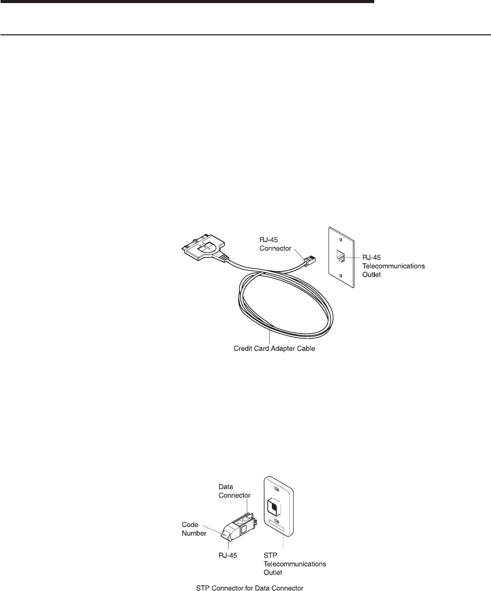
2. Determine which type of network cabling you will be using as shown in
the following figures, and connect the PC Card cable to the network as
described.
vIf your network uses UTP cabling, attach the RJ-45 (8-pin modular)
connector on the PC Card cable (P/N 38H7044) to the RJ-45
telecommunications outlet.
vIf your network uses STP cabling, attach the RJ-45 connector on the
PC Card cable (P/N 38H7044) to the RJ-45 end of the STP connector
(P/N 73G8314). Attach the STP connector to the STP
telecommunications outlet.
The STP connector has been specifically designed to work with the
IBM Token-Ring PC Cards.
Note: Verify that you are using the correct STP connector. The correct
STP connector and PC Card cable have the code number 100 on
the connectors that attach to each other.
© Copyright IBM Corp. 1997, 1999 5
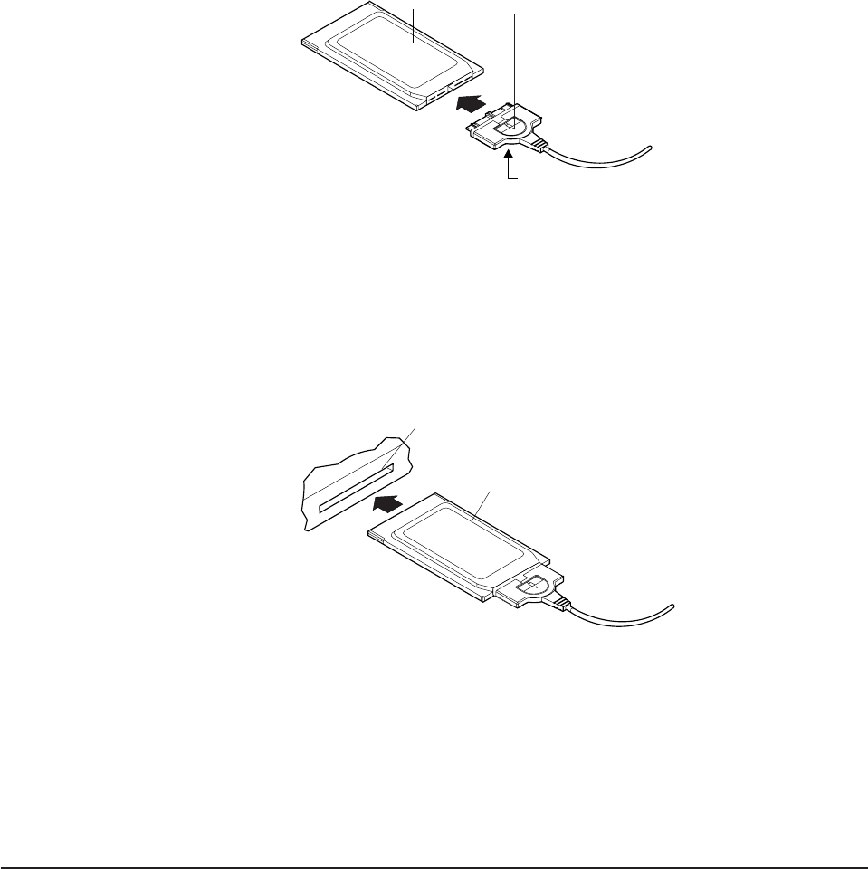
3. To attach the cable to the PC Card, move the latching button (the
half-circle in the center of the PC Card connector) toward the cable. The
cable cannot be connected or disconnected unless the latch is retracted.
Attach the cable to the PC Card with the part number on the bottom.
The connector is keyed to attach to the PC Card only one way. If you
feel any resistance, remove the connector, turn it over, and reattach it.
Part Number
(on bottom)
Latching ButtonPC Card
4. To lock the cable securely, move the latching button in toward the PC
Card. In some cases, you might want to leave the PC Card cable latch
retracted. If the PC Card cable is pulled, it will disconnect from the PC
Card, possibly saving your computer from being pulled off a table.
5. Insert the PC Card in the slot. If you are using a point enabler, note
which slot you use.
PC Card
PC Card Slot
The PC Card is keyed to go in only one way. If you feel resistance
before the PC Card is fully inserted, remove the PC Card, turn it over,
and reinsert it.
6. Switch ON (|) the power to the computer.
7. Return to page 3 to continue. Step 3 of the Installation Checklist is now
complete.
Removing the PC Card
Note: If you are using Card and Socket Services, you may be able to use
hot-pluggability
features with your PC Card. See “Hot-Pluggability and
Suspend/Resume Issues” on page 7 for more information.
Follow these steps to remove the PC Card:
6Turbo 16/4 Token-Ring PC Card 2

1. Switch OFF (O) the power to the computer.
2. With the cable still attached to the PC Card, pull the PC Card from the
computer.
3. To detach the cable from the PC Card, retract the latching button (the half-circle
in the center of the connector) by moving it toward the cable.
4. Grasp the connector and unplug it from the PC Card.
5. Store the PC Card.
Note: When the cable is removed from the PC Card, the PC Card appears to
the system as if it has been physically removed from the socket.
Hot-Pluggability and Suspend/Resume Issues
The DOS ODI, DOS NDIS, OS/2 ODI, OS/2 NDIS, Card Wizard 4.1 and 5.0 on
Windows NT, Windows 95 and Windows 98 (NDIS 3) drivers support a level of
hot-pluggability
and Suspend/Resume. Hot-pluggability refers to the ability to
remove and insert your card at any time while the machine is running. If you follow
these guidelines, no damage will occur to either your PC Card, machine, or
software. Hot-plugging has the advantage of allowing you to remove your card
when you are using battery power, thus reducing the drain on your battery. It also
provides greater freedom in using portable computers in a portable manner. The
IBM Turbo 16/4 Token-Ring PC Card 2 appears to be removed physically from a
system when the cable is removed. The PC Card appears to the system to be
inserted when its cable is reattached to the PC Card. This makes it possible to
hot-plug the PC Card without physically removing it from the socket. Attach or
remove your cable instead of physically removing the PC Card.
To use the hot-plugging features of this card, you must:
vUse Card and Socket Services. If you are using a point enabler,
do not
attempt
to unplug your card while the machine is powered on. You might damage both
your card and the machine in this case.
vUse the Windows 95, DOS ODI environment, DOS NDIS environment, OS/2 ODI
environment, or OS/2 NDIS environment. At the present time the DOS Native
environment does not support hot-pluggability. Removing your card while using
this environment might result in a system failure or the inability to access your
LAN applications.
vDo not hot-plug a card when in a Windows for Workgroups environment. Your
card does not have to be present when NET START is run. If you plan to access
your network in your Windows session, insert your card before starting Windows.
If you plan to pull out your card, shut down Windows before doing so. It is
suggested that you include your Network Address in the protocol.ini if you
execute NET START without a card present. This ensures that the system has
your card’s address even if the card is not present.
The following sections describe, in more detail, the exact procedure to follow for
each of the supported hot-plugging environments.
Windows 95 and Windows 98
Windows 95 and Windows 98 have built-in support for hot plugging and
suspend/resume. They recognize the PC Card when it is inserted into a PCMCIA
socket (or the cable is attached to an inserted PC Card) and load the correct driver
and configured protocol stack for the PC Card.
Chapter 3. Inserting and Removing the PC Card 7
If you plan to disconnect from your network, click the PC Card icon on the status
bar. A message box appears with a message to stop the PC Card. Click this box.
When the Safe to remove message appears, you can either remove the cable or
physically remove your PC Card.
DOS ODI Hot-Pluggability and Suspend/Resume
It is recommended that you use the NetWare Event Service Layer program
(NESL.COM) for hot-plugging to work in this environment. Without this support, you
should use the following procedure.
To remove the card or go into a suspend mode, you must first unload all the
drivers. This is done by removing them in the reverse order they were installed.
This can be accomplished by typing the following commands at the DOS prompt:
netx u (or vlm u)
ipxodi u
tokencs u
lsl u
At this point, you can remove the card from your machine. Once the card is
removed, you can enter and exit suspend mode as often as you like before
reinstalling the card. It is best to reinstall the card while the machine is not in
suspend mode.
After reinserting the card or resuming, you can restart your network software by
typing the following commands at the DOS prompt:
lsl
tokencs
ipxodi
netx
DOS NDIS Hot-Pluggability
You can insert and remove your card before and after using Windows for
Workgroups. You cannot hot-plug the card while using Windows for Workgroups.
Insert the card before starting the software. Remove the card only after exiting the
Windows for Workgroups environment.
OS/2 NDIS Hot-Pluggability and Suspend/Resume
You can remove the card or go into suspend mode at any time as long as you are
not running any applications that use shared resources. After you reinsert the card
or resume, you should have all of your LAN shared resources connected. If you use
CM/2 to connect to the host, you will have to log on again.
One scenario that does not work is suspending and then removing the card. The
card will not be recognized when it is reinserted. If you want to do something like
this, you must first remove the card and then suspend. You can then resume later
and reinsert the card later.
8Turbo 16/4 Token-Ring PC Card 2

Chapter 4. Software Installation
1. Get the latest level of LAN driver updates for your operating system to ensure
that your code is at the latest level.
2. Be sure that your IBM Turbo 16/4 Token-Ring PC Card 2 has already been
installed in your computer. If it has not, follow the instructions in “Chapter 3.
Inserting and Removing the PC Card” on page 5.
3. Get the driver for your environment. There are three places to find the driver. If
you have a Web connection, we recommend the first one listed here. All three
methods will place the driver in a directory according to the structure in Table 1.
vMethod A: Get the driver from a software package on the IBM Networking
Hardware Division home page on the Web. This will ensure that you get the
latest driver. Go to x:\startcd.htm (where x is your CD-ROM drive). Select
IBM Networking Web site — product support. Select Downloads and
choose the appropriate software package for your environment. Run the
package to expand the files.
Note: You can also access the Web site directly at
www.networking.ibm.com/support
vMethod B: Use the driver shipped on this CD-ROM directly with your network
operating system’s installation software.
vMethod C: Get the driver from a software package shipped on this CD-ROM.
Point your Web browser to x:\startcd.htm (where x is your CD-ROM drive).
Select CD-ROM — product support. Select Downloads and choose the
appropriate software package for your environment. Run the package to
expand the files.
4. Install the driver. Use Table 2 and Table 3 on page 10 to find the location of the
installation instructions for your environment. It is recommended that you install
the latest service pack for your operating environment before installing the PC
Card software.
Table 1. Driver File Directory Structure
Operating System Directory
Windows 9x \ (root)
Windows NT \ (root)
Windows 2000 \ (root)
Novell NetWare Server and Client \NOVELL\NETWARE
Novell NetWare DOS Requester (16-bit) \NOVELL\DOS
OS/2 \ (root)
DOS \DOS
Windows for Workgroups \WFW
If you are using one of the environments listed in Table 2, you will not use LANAID.
Where to Find the Installation Instructions for Your Environment
Table 2. Do not use LANAID to configure your machine
Novell NetWare 3.12 Server page 11
Novell NetWare 4.11 Server page 14
Novell NetWare 5.0 Server page 17
© Copyright IBM Corp. 1997, 1999 9

Table 2. Do not use LANAID to configure your machine (continued)
Novell Client DOS/Windows 3.1x page 19
Novell NetWare Client32 for Windows 95 page 19
Windows 95/Windows 98 page 23
Windows NT 3.51 page 24
Windows NT 4.0 page 25
Windows 2000 page 25
Remote Unattended Install for Windows 95, Windows 98,
and NT 4.0 page 25
OS/2 NDIS 2 Device Driver Using MPTS page 26
OS/2 NDIS 2 Device Driver Using Other Installation
Programs page 27
ODI 16-bit Client page 28
If you are using the environment listed in Table 3, you will use LANAID to configure
your machine. Even though the network operating system appears to fully install
and configure the device driver, it is highly recommended that you run LANAID to
ensure that the PC Card is appropriately configured.
Table 3. Use LANAID to configure your machine
Microsoft Windows for Workgroups/NDIS 2 page 27
Note: If you are operating in a server environment, you might not get support from
your hardware or network operating system manufacturers.
Novell Installation
Novell NetWare Server Driver and PCMCIA Bus Support
Card Services and Point Enablers: What Works and What Does
Not
IBMTOKEN.LAN is used in both the NetWare Server and Client environments. In
order to use this driver, your system must enable the card by loading: Socket
Services, Card Services, and CS20TOK.EXE. POINTTR.EXE is not supported with
IBMTOKEN.LAN.
If Card Services on your system is earlier than version 5.00, enter the following
parameter when you load the driver: MEM1=<SRAM Address>
LOAD IBMTOKEN.LAN FRAME=TOKEN-RING MEM1=C8000
If you do not put this parameter on the driver load line, you will be prompted for this
parameter every time you load the driver.
If your Card Services is version 5.00 or higher, you do not need to worry about this
parameter.
CS20TOK.EXE Configuration
CS20TOK.EXE is a small software program that configures the PC Card socket
controller to allocate resources (memory, I/O Ports, interrupts, DMA channels, and
10 Turbo 16/4 Token-Ring PC Card 2
power) to PCMCIA cards. Once CS20TOK.EXE has run successfully, the PCMCIA
Token-Ring card is ready to operate and looks much like any ISA Token-Ring
adapter.
Generally, enabling a card is done by loading CS20TOK.EXE in CONFIG.SYS,
AUTOEXEC.BAT, or at a DOS prompt.
For a complete list of CS20TOK.EXE parameters, you can enter the following at a
DOS prompt:
CS20TOK /? or CS20TOK /h
Examples:
In autoexec.bat:
cs20tok sa mmio=d000 sram=d000,4 rs=16 irq=a io=0a20
In config.sys:
device=c:\cs20tok.exe sa mmio=d000 sram=d000,4 rs=16 irq=a io=0a20
Both set the card in slot 1 (sa) to an 8-KB memory region based at X'0D0000', with
the card operating in enhanced mode. The card is assigned port X'0A20', interrupt
vector X'A' (10 decimal), and Token-Ring speed (rs) will be 16 Mbps. The program
runs, then sounds two ascending beeps indicating successful operation. The card is
now enabled and ready for the driver to be loaded.
Here is an example of using CS20TOK.EXE with two adapters:
cs20tok sa mmio=d000 sram=d000,4 rs=16 irq=a io=0a20 pri
cs20tok sb mmio=c800 sram=c800,4 rs=16 irq=9 io=0a24 alt
Novell NetWare 3.12 Server
Before you start this installation, get the latest level of patches for NetWare 3.12
from Novell. The current level is IntraNetWare Support Pack Version 5.0 from the
Novell support Web site at support.novell.com. You will install the patches during
the following procedure.
If the Novell NetWare server is not on your computer, use the following instructions.
If it is on your computer, go to the instructions on page 13.
Server Driver Installation in New NetWare 3.12 Server
Changes from the usual NetWare installation are necessary because this driver is
written to a new specification level that requires new NetWare loadable modules
(NLMs). The installation program is not aware of this, though, and these NLMs must
be loaded during installation of the server device driver and after the server
installation.
1. Create a diskette containing the extracted files from the NETWARE.EXE
package file on the IBM Turbo 16/4 Token-Ring PC Card 2 CD-ROM.
2. Refer to Novell’s
Installation and Upgrade
manual for installation instructions.
Follow the procedure for the installation of Novell NetWare 3.12 until the
section titled ″Load LAN Drivers″is next.
3. Insert the diskette that you created in step 1 into drive A. Enter the following
commands at the server prompt:
LOAD A:\NOVELL\NETWARE\NBI31X.NLM
LOAD A:\NOVELL\NETWARE\MSM31X.NLM
LOAD A:\NOVELL\NETWARE\TOKENTSM.NLM
Chapter 4. Software Installation 11
Note: A message referring to
protected-mode BIOS access
might appear
before installation of Novell patches. It is for information only and can
be ignored.
4. Load the server device driver. Enter the following command at the server
prompt:
LOAD X:\NOVELL\NETWARE\IBMTOKEN.LAN DATARATE=M16
In server environments, the DataRate should be set to M16 or M4, and clients
should be set to Auto. The default is Auto.
Note: See “Novell NetWare Server Driver Parameters” on page 20 for a
complete list of parameters that can be specified in the LOAD
IBMTOKEN command in the AUTOEXEC.NCF file.
5. Follow the instructions in the Novell manual, beginning with ″Bind the Protocol
to the LAN Driver″and continue until you are in the File Server STARTUP.NCF
File panel.
6. In addition to the instructions in the Novell manual, add the following line to
STARTUP.NCF:
Set Minimum Packet Receive Buffers = 48
Note: Increase the minimum packet receive buffers by 48 for each additional
adapter that is installed.
7. Perform the instructions in ″Create an AUTOEXEC.NCF file″in the Novell
manual. Add the following lines to the AUTOEXEC.NCF file immediately after
the IPX INTERNAL NET statement (replace C:\SERVER.312\ with the location
of the NetWare server program):
LOAD C:\SERVER.312\NBI31X.NLM
LOAD C:\SERVER.312\MSM31X.NLM
LOAD C:\SERVER.312\TOKENTSM.NLM
LOAD C:\SERVER.312\IBMTOKEN.LAN NAME=IBMLS1 DATARATE=M16
BIND IPX TO IBMLS1 NET=<unique net number>
Make sure that the line containing IBMTOKEN.LAN has the complete path
name.
Notes:
a. See “Novell NetWare Server Driver Messages” on page 50 for a complete
list of parameters that you can specify on the LOAD IBMTOKEN command
in the AUTOEXEC.NCF file.
b. If you experience any problems after loading the Novell NLM files, contact
Novell to ensure that you have the current version of these files.
Press Esc and answer Yes to save the new file to disk. Press Esc again to
return to the server console.
8. Shut down your server by entering down and then entering exit from the server
prompt.
9. Make sure that the diskette that you created in step 1 is inserted in drive A.
Enter the following commands at the server prompt. You might be prompted to
perform a file overwrite; it is OK to overwrite these files.
COPY A:\NOVELL\NETWARE\NBI31X.NLM C:\SERVER.312
COPY A:\NOVELL\NETWARE\MSM31X.NLM C:\SERVER.312
COPY A:\NOVELL\NETWARE\TOKENTSM.NLM C:\SERVER.312
COPY A:\NOVELL\NETWARE\IBMTOKEN.LAN C:\SERVER.312
COPY A:\NOVELL\NETWARE\IBMTOKEN.LDI C:\SERVER.312
12 Turbo 16/4 Token-Ring PC Card 2
10. Go to the Novell server directory and enter server at the DOS prompt to
restart the server.
11. Install the patches obtained earlier now. Make sure to select the v3.31 ODI
LAN Updates for Hardware if given the opportunity.
12. Installation is now complete.
Check for the following conditions to determine whether the adapter is working
correctly and whether installation is complete:
vThe device driver files are loading successfully.
vThere are no error messages.
If you experience problems, go to “Appendix B. Problem Determination” on
page 49.
For information concerning NetWare server error messages, see “Novell
NetWare Server Driver Parameters” on page 20.
Server Driver Installation in Existing NetWare 3.12 Server
If Novell NetWare is on your computer, perform the following steps to install the
adapter server device driver.
1. Create a diskette containing the extracted files from the NETWARE.EXE file on
the IBM Turbo 16/4 Token-Ring PC Card 2 CD-ROM.
2. Install the patches obtained earlier now. Make sure to select the v3.31 ODI
LAN Updates for Hardware if given the opportunity. Return to the server
console when the installation is complete.
3. Make sure that the diskette you created in step 1 has been inserted in drive A.
Enter the following commands at the server prompt. You might be prompted to
perform a file overwrite; it is OK to overwrite these files.
COPY A:\NOVELL\NETWARE\NBI31X.NLM C:\SERVER.312
COPY A:\NOVELL\NETWARE\MSM31X.NLM C:\SERVER.312
COPY A:\NOVELL\NETWARE\TOKENTSM.NLM C:\SERVER.312
COPY A:\NOVELL\NETWARE\IBMTOKEN.LAN C:\SERVER.312
COPY A:\NOVELL\NETWARE\IBMTOKEN.LDI C:\SERVER.312
Note: If you experience any problems after loading the Novell NLM files,
check the Novell Web site to ensure that you have the current version
of these files.
4. In the directory where Novell is installed on your hard disk, enter server at the
DOS prompt to start the server.
5. At the server console prompt, enter load install.
6. From the Installation Options menu, select System Options and press Enter.
7. Select Edit STARTUP.NCF File and press Enter. Add the following line to the
STARTUP.NCF file:
Set Minimum Packet Receive Buffers = 48
Note: Increase the minimum packet receive buffers by 48 for each additional
adapter that is installed.
8. Press Esc and then answer Yes to save changes to the STARTUP.NCF file.
9. Select Edit AUTOEXEC.NCF File and press Enter. Edit this file and, after the
IPX internal net statement, include the following statements. (Replace
C:\SERVER.312\ with the location of the NetWare server program.)
In a server environment, set the DataRate to M16 or M4, and clients to Auto.
The default is Auto.
Chapter 4. Software Installation 13
LOAD C:\SERVER.312\NBI31X
LOAD C:\SERVER.312\MSM31X
LOAD C:\SERVER.312\TOKENTSM
LOAD C:\SERVER.312\IBMTOKEN NAME=IBMLS1 DATARATE=M16
BIND IPX TO IBMLS1 NET=<unique net number>
See “Novell NetWare Server Driver Parameters” on page 20 for a complete list
of parameters that can be specified on the LOAD IBMTOKEN command in the
AUTOEXEC.NCF file.
Press Esc and then answer Yes to save the new file to disk. Press Esc again
to return to the server prompt.
10. Shut down your server by entering down and then entering exit from the
server prompt.
11. Enter server to restart the server.
12. Installation is now complete. Shut down and restart your computer for all
changes to take effect.
Check for the following conditions to determine whether the adapter is working
correctly and whether installation is complete:
vThe device driver files are loading successfully.
vThere are no error messages.
If you experience problems, go to “Appendix B. Problem Determination” on
page 49.
For information concerning NetWare server error messages, see “Novell
NetWare Server Driver Messages” on page 50.
Novell NetWare 4.11 Server
Before you start this installation, get the latest level of patches for NetWare 4.11
Server from Novell. The current level is IntraNetWare Support Pack Version 5.0
from the Novell support Web site at support.novell.com. You will install the patches
during the following procedure.
If Novell NetWare is not on your computer, use the following instructions. If it is on
your computer, follow the instructions on page 16.
Server Driver Installation in New NetWare 4.11 Server
Changes from the usual NetWare installation are necessary because this driver is
written to a new specification level that requires new NetWare loadable modules
(NLMs). The installation program is not aware of this, though, and these NLMs must
be loaded during installation of the server device driver and after the server
installation.
Note: A message referring to protected-mode BIOS access might appear before
installation of Novell patches. It is for information only, and can be ignored.
1. Create a diskette containing the extracted files from the NETWARE.EXE
package file on the IBM Turbo 16/4 Token-Ring PC Card 2 CD-ROM.
2. When you see INSTALL Found the following: IBM Turbo 16/4 Token-Ring PC
Card 2
xxxx xxxx xxxx
, press Enter. The actual numbers vary by product.
Then press the Insert (INS) key to install the unlisted driver.
14 Turbo 16/4 Token-Ring PC Card 2
3. Press ALT-ESC to toggle to the server console, and enter the following LOAD
statements (make sure that the diskette that you created in step 1 is inserted
in drive A):
LOAD A:\NOVELL\NETWARE\MSM.NLM
LOAD A:\NOVELL\NETWARE\TOKENTSM.NLM
4. Press ALT-ESC to toggle back to the INSTALL panel.
5. Press F3 on the next panel to specify A:\NOVELL\NETWARE as the directory
path.
Press Enter, then follow the instructions on the panel to complete the
installation of the driver. If you need to make any custom configuration
changes to the driver, do so at this time.
6. Follow the instructions in the Novell manual to
Create an AUTOEXEC.NCF file
.
In addition to the instructions in the manual, add the following lines to the
AUTOEXEC.NCF file immediately after the IPX INTERNAL NET statement (if
necessary, replace C:\NWSERVER with the location of the SERVER.EXE
executable):
LOAD C:\NWSERVER\NBI.NLM
LOAD C:\NWSERVER\MSM.NLM
LOAD C:\NWSERVER\TOKENTSM.NLM
LOAD C:\NWSERVER\IBMTOKEN.LAN NAME=IBMLS1 DATARATE=M16
Note: There will be existing LOAD and BIND IPX statements in the
AUTOEXEC.NCF. Delete the LOAD statement (we have replaced it with
stated LOAD C:\NWSERVER\IBMTOKEN.LAN statement). Also, make
any needed modifications to the existing BIND IPX statement (refer to
the
Bind the Protocol to the LAN Driver
section of the Novell manual for
additional information).
See “Novell NetWare Server Driver Parameters” on page 20 for a complete list
of parameters that can be specified on the LOAD IBMTOKEN command in the
AUTOEXEC.NCF file.
7. Press ESC and answer YES to save the new file to disk. Press ESC again to
return to the server console.
8. Type the following commands from the server prompt to shut down the server
and exit to DOS: down, then exit.
9. Perform the following COPY commands, making sure that the diskette that you
created in step 1 is inserted in drive A. Note that it will prompt you at each of
the following files to ask if you want to perform a file overwrite; it is OK to
overwrite these files.
COPY A:\NOVELL\NETWARE\NBI.NLM C:\NWSERVER
COPY A:\NOVELL\NETWARE\MSM.NLM C:\NWSERVER
COPY A:\NOVELL\NETWARE\TOKENTSM.NLM C:\NWSERVER
COPY A:\NOVELL\NETWARE\IBMTOKEN.LAN C:\NWSERVER
COPY A:\NOVELL\NETWARE\IBMTOKEN.LDI C:\NWSERVER
10. Go to the Novell server directory and enter server at the DOS prompt to
restart the server.
11. Install the latest available Novell patches for NetWare 4.11 now. Make sure to
select the Version 3.31 ODI LAN Updates for Hardware if given the opportunity.
12. Issue the following commands from the server prompt to bring the server
down, then restart it: down, then restart server.
13. Installation is now complete. Check for the following conditions to determine
whether the adapter is working correctly and whether installation is complete:
vThe device driver files are loading successfully.
vThere are no error messages.
Chapter 4. Software Installation 15
If you experience problems, go to “Appendix B. Problem Determination” on
page 49 .
For information concerning NetWare server error messages, see “Novell
NetWare Server Driver Messages” on page 50.
Server Driver Installation in Existing NetWare 4.11 Server
If Novell NetWare is in your computer, perform the following steps to install the
adapter server device driver.
Note: If you are altering the configuration of a previously-loaded adapter, unload
that adapter before proceeding with these instructions.
1. Create a diskette containing the extracted files from the NETWARE.EXE file on
the IBM Turbo 16/4 Token-Ring PC Card 2 CD-ROM.
2. Be sure that your IBM Turbo 16/4 Token-Ring PC Card 2 is already in your
computer. If it is not, follow the instructions in “Chapter 2. Installation” on
page 3.
3. Install the latest available Novell patches for NetWare 4.11. Make sure to
select the Version 3.31 ODI LAN Updates for Hardware if given the
opportunity. Return to the server console when the installation is complete.
4. Down and restart server from the server prompt to bring the server down,
then restart it again.
5. Check to see if the device driver is loaded. If it is, unload it using the following
command: unload token or unload ibmtoken
6. Type load install on the server.
7. Select Driver Options.
8. Select Configure Network Drivers.
9. Select Select Drivers.
10. On the next panel, press the Insert (INS) key to install the unlisted driver.
11. Insert the diskette that you created in step 1; press F3 on the next panel and
specify the path A:\NOVELL\NETWARE.
12. Follow the instructions on the panels to complete the installation of the driver.
If you need to make any custom configuration changes to the driver, do so at
this time.
13. Follow the instructions in the Novell manual to
Create an AUTOEXEC.NCF file
.
In addition to the instructions in the manual, add the following lines to the
AUTOEXEC.NCF file, immediately after the IPX INTERNAL NET statement. If
necessary, replace C:\NWSERVER with the actual location of the
SERVER.EXE executable.
LOAD C:\NWSERVER\NBI.NLM
LOAD C:\NWSERVER\MSM.NLM
LOAD C:\NWSERVER\TOKENTSM.NLM
LOAD C:\NWSERVER\IBMTOKEN.LAN NAME=IBMLS1 DATARATE=M16
Note: There will be existing LOAD and BIND IPX statements in the
AUTOEXEC.NCF. Delete the LOAD statement (we have replaced it with
the stated LOAD C:\NWSERVER\IBMTOKEN.LAN statement).
Also, make any needed modifications to the existing BIND IPX statement.
Refer to the
Bind the Protocol to the LAN Driver
section of the Novell manual
for additional information.
16 Turbo 16/4 Token-Ring PC Card 2
See “Novell NetWare Server Driver Parameters” on page 20 for a complete list
of parameters that can be specified on the LOAD IBMTOKEN command in the
AUTOEXEC.NCF file.
14. Press ESC and answer YES to save the new file to disk. Press ESC again to
return to the server console.
15. Type the following commands from the server prompt to shut down the server
and exit to DOS: down, and then exit.
16. Perform the following COPY commands, making sure that the diskette that you
created in step 1 is inserted in the diskette drive. Note that it will prompt you at
each of the following files to ask if you want to perform a file overwrite; it is OK
to overwrite these files.
COPY A:\NOVELL\NETWARE\NBI.NLM C:\NWSERVER
COPY A:\NOVELL\NETWARE\MSM.NLM C:\NWSERVER
COPY A:\NOVELL\NETWARE\TOKENTSM.NLM C:\NWSERVER
COPY A:\NOVELL\NETWARE\IBMTOKEN.LAN C:\NWSERVER
COPY A:\NOVELL\NETWARE\IBMTOKEN.LDI C:\NWSERVER
17. Go to the Novell server directory and enter server at the DOS prompt to
restart the server.
18. Installation is now complete. Check for the following conditions to determine
whether the adapter is working correctly and whether installation has been
completed successfully:
vThe device driver files are loading successfully.
vThere are no error messages.
If you experience problems, go to “Appendix B. Problem Determination” on
page 49.
For information concerning NetWare server error messages, see “Novell
NetWare Server Driver Messages” on page 50.
Novell NetWare 5.0 Server
Server Driver Installation During NetWare 5.0 Server Installation
Installation of the network board and its device driver occurs during the combined
storage device and network board installation step. Use the following instructions to
install the network board and its driver during a new NetWare 5.0 server installation.
1. Create a device driver installation diskette.
Create a diskette containing the extracted files from the NETWARE.EXE
package file on the IBM Turbo 16/4 Token-Ring PC Card 2 CD-ROM.
2. During the installation program, when you get to Select a Storage Device and a
Network Board:
vSelect and configure the storage device
vSelect and configure the network board
vLoad a NetWare Loadable Module TM program (if required)
3. Select a Storage Device
Storage devices such as hard disks, CD-ROMs, and tape devices require a
software driver to communicate with the storage adapter. The software driver for
the storage device is called a custom device module (CDM). Each type of
storage device requires a CDM.
The installation program auto-detects many types of storage devices such as
IDE drives, SCSI drives, CD-ROM drives, and tape drives. If your storage
Chapter 4. Software Installation 17
device is not detected, choose the appropriate driver from the list of available
drivers provided with NetWare 5.0. You can also add a new driver from a
diskette. CDMs can be obtained from the storage device manufacturer.
4. Select a Network Board
The software driver for a network board is called a LAN driver.
The installation program auto-detects many types of network boards. If your
network board is not detected, choose the driver for the network board from the
list provided with NetWare 5.0. You can also use a new or updated driver from
the diskette that you created in step 1.
The network board must be installed and configured correctly. For servers, it is
recommended that DATARATE is set to M16 or M4, and clients be set to Auto.
You might be able to influence certain network board properties by configuring
the system and the network board or both.
5. Load a NetWare Loadable Module (if required)
Certain server and network configurations might require you to load a NetWare
Loadable Module (NLM) before you can complete the server installation. An
example is loading ROUTE.NLM for a Token-Ring environment that requires it.
Server Driver Installation in Existing NetWare 5.0 Server
The following procedure explains how to use NWCONFIG to load a LAN driver and
bind a protocol.
1. Create a diskette that contains the extracted files from the NETWARE.EXE
package file on the IBM Turbo 16/4 Token-Ring PC Card 2 CD-ROM.
2. At the server console prompt, enter NWCONFIG
3. Select Driver Options > Configure network drivers.
4. To select a driver from all of the available drivers, choose Select a driver. The
screen will display a list of all available drivers.
5. Press Insert. Follow the instructions on the panels. Use the diskette that you
created in step 1 when you are prompted to supply an unlisted driver. The
directory is A:\NOVELL\NETWARE.
Note: For some drivers, a message might appear indicating that the driver
must be loaded manually (at the console prompt). To load a driver
manually, follow the screen prompts or press F1 for more information.
6. Set protocols. When the window containing protocol choices is displayed,
select the protocol that you want to use and press the spacebar. If you select
TCP/IP, enter the IP address and the IP mask.
7. Set parameters. Use the down arrow key to move the cursor to the parameter
window. Enter parameter values as needed. Press F1 for help. It is
recommended for servers that the Data Rate is set to 4 Mbps or 16 Mbps, and
clients be set to Automatic.
In some cases, the system displays a pop-up list of values for the field from
which you select the desired value. In other cases, you must type in a value
and press Enter to move to the next field.
8. To specify a particular frame type for a Token-Ring driver, press F3 to display a
list of frame types. Use the arrow keys to move up and down the list. Press
Enter to select a frame type. When finished, press F10. If you do not specify a
particular frame type, all frame types are loaded automatically, but only those
found on the network are actually bound to the driver.
9. Select Save parameters and load driver.
10. Confirm bindings of the protocol with the driver and the network number.
18 Turbo 16/4 Token-Ring PC Card 2
11. Driver installation is now complete. To add another adapter, down the server,
power off the server, and insert the additional adapter. NetWare will load the
appropriate driver automatically. Then repeat step 10.
Novell Client DOS/Windows 3.1x
1. Download Novell Client DOS/Windows 3.1x Version 2.5 or higher from the
Novell Web site (support.novell.com). Unzip the downloaded file to a directory
on your computer.
2. Exit Windows.
3. From a DOS prompt, go to the driectory where you put the file. Run
INSTALL.EXE.
4. Select Yes or No to respond to the Novell License Agreement.
5. Select Novell Client Windows Support and Work Station Manager 3.X.
Press F10 to save and continue.
6. Select 32–bit LAN Drivers and press F10 to save and continue.
7. Select USER SPECIFIED 32–Bit Driver and press Enter. Insert the CD-ROM
or the diskette that contains the device drivers into the appropriate drive. Enter
the path to the 32–bit ODI driver: x:\novell\netware where x is your CD-ROM
drive letter. The panel should say
IBM Token-Ring PCMCIA
Press Enter, configure the parameters, and press F10 to save and continue.
8. At the Installation Configuration Summary panel, confirm that the values are
what you selected, and press F10 to save and continue.
9. The files will be copied at this point.
10. Installation is now complete.
11. Reboot your computer and start Windows to connect to and login to your
server.
12. Check for the following conditions to determine whether the adapter is working
correctly and whether installation has been completed successfully:
vThe device driver files are loading successfully.
vThere are no error messages.
If you experience problems, go to “Appendix B. Problem Determination” on
page 49.
Novell NetWare Client32 for Windows 95
(Previous version is IntranetWare Client for Windows 95.)
Note: You will need the Windows 95 diskettes or CD-ROM to complete this
installation.
If you are installing on a workstation that already has Windows 95 installed using
Novell IntranetWare Client Version 2.2 for Windows 95, use the following procedure.
Note: IntranetWare Client Version 2.2 for Windows 95 or Novell Client Version 2.5
for Windows 95 can be downloaded from Novell on the Web at
support.novell.com
Chapter 4. Software Installation 19

If you are upgrading from the NetWare DOS Requester (VLM) client or if you do not
have any network client installed, you need to have the Windows 95 CD-ROM or
diskettes or the Windows 95 .CAB files.
1. If the NDIS driver is not already installed, install it using the instructions in
“Windows Installation” on page 23.
2. After downloading the code, run the installation program (SETUP.EXE) for
Novell IntranetWare Client Version 2.2 for Windows 95 or Novell Client Version
2.5 for WIndows 95.
3. Select Yes or No to respond to the Novell License Agreement.
4. Select Start to begin the installation.
If you are prompted to select an adapter, select one that matches your
hardware. This step might not be necessary, as you should have already
selected the adapter in the first step.
5. If you do not need to customize your installation, select Reboot.
6. If you want optional features or need to configure your workstation, select
Customize. Then select Reboot.
Novell NetWare Server Driver Parameters
For the Novell NetWare server, the parameters are set on the command line or on
the load IBMTOKEN line in the AUTOEXEC.NCF file.
Table 4. Novell NetWare Driver Parameters
Parameter Explanation
DATARATE= Configures the Token-Ring data rate for the PC Card. It is
recommended for servers that the DATARATE be set to M16 or M4,
and clients be set to AUTO.
Valid values:
AUTO AutoSense – automatic ring-speed detection.
Note: The PC Card will not function with AutoSense if it is
the first one on the ring. AutoSense is not designed for
changing ring speed while the PC Card is operational. It is
usually necessary to reload the driver.
M16 16-Mbps ring speed operation.
M4 4-Mbps ring speed operation.
The default is AUTO.
Note: If using Novell NetWare SFTIII, M16 or M4 must be selected
for the DATARATE parameter on both of the SFTIII machines. Do
not use AUTO.
FRAME= This string defines the frame type to be used with the PC Card
when loading the IBMTOKEN LAN driver.
Token-Ring drivers can add most-significant bit (MSB) or
least-significant bit (LSB) following the frame type designation. LSB
forces canonical addresses to be passed between the MLID and
the upper layers. The MSB designation forces non-canonical
addresses to be passed (this is the default for Token-Ring media).
Valid values:
TOKEN-RING or TOKEN-RING_SNAP
The default is TOKEN-RING.
20 Turbo 16/4 Token-Ring PC Card 2

Table 4. Novell NetWare Driver Parameters (continued)
Parameter Explanation
FULLDUPLEX= This keyword permits the IBMTOKEN LAN driver to activate
Token-Ring full-duplex operation supported by the PC Card and the
NetWare server environment.
Valid values:
YES, NO
The default is YES.
MEM1= The MEM1 keyword is needed if you are using a Card Services
version earlier than version 5.00. This value is the base shared
RAM address that your adapter is configured to use. If it is not
specified, you will be prompted for this parameter when the driver
loads. If you are using a version of Card Services which is 5.00 or
higher, this parameter is not needed..
Valid values:
C0000, C4000, C8000, CC000, D000, D4000, D8000,
DC000
There is no default for this parameter.
NODE= This keyword is used to set a locally administered address for the
PC Card. A local address must contain 12 hexadecimal characters
and can be specified in either most-significant bit (MSB) or
least-significant bit (LSB) format.
To specify an MSB node address, the letter M immediately follows
the last digit of the node address. To specify an LSB node address,
the letter L immediately follows the last digit of the node address. If
neither an M nor L is specified after the last digit of the node
address, MSB will be assumed.
If a node address is specified in MSB format, the value must be
within the range X'400000000000' to X'7FFFFFFFFFFF' (for
example, X'400000000002'M). This same address specified in LSB
format would be X'020000000080'L with an L optionally appended
to the end.
Notes:
1. Do not assign the same local address to two or more stations.
Severe station communication or network failures can occur
when two or more stations are assigned the same address.
2. If you do not assign a locally administered address, the PC
Card uses the universally administered address permanently
encoded in its memory.
SLOT= This keyword defines the slot number of the corresponding PC
Card in the computer. To avoid being prompted to enter a slot
number when the IBMTOKEN LAN driver is loaded, specify this
keyword. One SLOT number is required for each NIC if you are
using more than one.
Chapter 4. Software Installation 21

Table 4. Novell NetWare Driver Parameters (continued)
Parameter Explanation
RT= Route Switching Mode. This parameter indicates whether the driver
should enable code that attempts to send routable traffic directly to
a destination rather than through the router. This can improve the
performance of these connections and reduce the workload at the
router. If the value is Disable, all routable frames will be sent
through the router.
Valid values:
AAutomatically determines whether to use Peer or Client
mode.
PCommunicates with a peer destination station to establish
a direct path.
CUses an MSS server to determine the direct path.
DDeactivates the route switching function for this PC Card.
The default is D.
RTTS= Route Switching Table Size. This parameter specifies the number of
entries allowed in the route table kept for Route Switching support.
This should be set equal to or greater than the number of remote
stations this station will send data to using routable IP frames. If it
is set too low, some of the traffic that could be sent directly will
instead be sent through the router.
Valid values: 16-1024
The default is 1024.
RTSM= Route Switching IP Subnet Mask. This parameter contains a
character string specifying the IP subnet mask for the IP subnet to
which this PC Card will attach. This value is entered as an IP
dotted-decimal value (for example, 255.255.255.0). This is a
mandatory parameter when the RTSWMode parameter is set to
Auto or Peer.
Valid values:
xxx.xxx.xxx.xxx
A dotted-decimal IP network number (15 characters
maximum).
Disable When not in use.
The default is Disable.
RTHT= Route Switching Holding Time. This parameter specifies the Route
Switching information holding time value. This determines how often
a remote station must refresh its Route Switching information which
pertains to this station.
Valid values:2to20
The default is 20.
22 Turbo 16/4 Token-Ring PC Card 2

Table 4. Novell NetWare Driver Parameters (continued)
Parameter Explanation
TPRn= TCP Port Range. This represents a set of parameters which
designate the transmit frame priority value for a specified TCP port
range. n is 1, 2, 3, 4, or 5. The format of this 9-digit hexadecimal
string is:
<PortNumber><PortNumber><PriorityValue>
where each PortNumber is a four-character hex value and
PriorityValue is a one-character hex value. The two PortNumber
fields define a starting and ending value that make up a range, with
the starting value less than or equal to the ending value.
Valid values:
PortNumber
0x0000 to 0xFFFF
PriorityValue
1to6
There is no default for this parameter.
UPRn= UDP Port Range. This represents a set of parameters which
designate the transmit frame priority value for a specified UDP port
range. n is 1, 2, 3, 4, or 5. The format of this 9-digit hexadecimal
string is:
<PortNumber><PortNumber><PriorityValue>
where each PortNumber is a four-character hex value and
PriorityValue is a one-character hex value. The two PortNumber
fields define a starting and ending value that make up a range, with
the starting value less than or equal to the ending value.
Valid values:
PortNumber
0x0000 to 0xFFFF
PriorityValue
1to6
There is no default for this parameter.
Windows Installation
Windows 95 and Windows 98
1. Insert the IBM Turbo 16/4 Token-Ring PC Card 2 in your computer and switch it
on. When Windows loads, it will alert you to the fact that new hardware was
found in your computer. If it does not, see “Troubleshooting and Error Codes” on
page 50.
2. When the Update Device Driver Wizard (Windows 95) or the Add New
Hardware Wizard (Windows 98) appears, insert the CD-ROM or diskette that
contains the driver files.
3. Follow the instructions on the panels to install the driver files for the IBM Turbo
16/4 Token-Ring PC Card 2. During installation, you might be prompted to insert
the diskette labeled IBM Shared RAM Token-Ring Adapter NDIS 3/4/5 Device
Drivers. At this point, click OK and select the path to the driver diskette or
CD-ROM in the copy files from box. You might also be prompted to insert the
Chapter 4. Software Installation 23
diskette labeled Windows 95/98. At this point, click OK and select the path to
the diskettes, CD-ROM, or hard disk where the Windows installation files are
located in the copy files from box.
4. When driver installation is complete, Windows will prompt you to reboot your
computer. The IBM Turbo 16/4 Token-Ring PC Card 2 will not function until you
do so.
Using the IBM Turbo 16/4 Token-Ring PC Card 2 with Texas
Instruments Cardbus Controllers and Windows 95 OSR2
Some portable PCs that have support for Cardbus PC Cards use the Texas
Instruments Cardbus socket controller. Windows 95 OSR2 (build 4.00.950B)
includes support for the chipset. IBM Token-Ring PC Cards will not function
correctly if:
vYour portable PC uses the Texas Instruments Cardbus controller chipset and
vYour installation of Windows 95 OSR2 uses the Cardbus drivers that shipped
with Windows 95 OSR2
If you are having problems getting your IBM Token-Ring PC Card to function and
you suspect that you have the Windows 95 Cardbus socket controller drivers
installed, follow the procedures below to determine if you need the Windows 95
Cardbus socket controller driver patch.
1. Right-click My Computer on the desktop and select Properties. This will bring
up the system control panel.
2. Check the version of Microsoft Windows 95. If the version is 4.00.950B, you are
running OSR2 and should continue reading; otherwise, you do not need the
patch.
3. Click the Device Manager tab in the system control panel and check to see if
you have the Cardbus Socket Controller devices installed by expanding the
PCMCIA socket section. If you do not have this device listed, then you do not
need the patch.
4. Click Start and select Find — Files or folders...
5. Search for the file cbss.vxd on the drive that contains your Windows installation
(usually C). When you find it, right-click the cbss.vxd file and select Properties.
6. Click the Version tab and check the version of the file. If the version is
4.00.1111, then you are using the Cardbus socket controller drivers that shipped
with Windows 95 OSR2. Contact the computer manufacturer to obtain a patch
for the Cardbus controller for Windows 95 OSR2.
Windows NT 3.51
1. Insert the IBM Turbo 16/4 Token-Ring PC Card 2 in your computer and switch it
on. When Windows NT loads, login to the computer and open the control panel.
Double-click Network.
2. Click Add Adapter and select <Other> Requires disk from manufacturer.At
this point, Windows NT will prompt you for your driver files. Select the path to
your driver diskette or CD-ROM and click OK.
3. When prompted to choose the adapter, select IBM Turbo 16/4 Token-Ring PC
Card 2. After installation is complete, the adapter should appear in the Installed
Adapter Cards window.
4. Select OK to close the network control panel. You might be prompted to
configure your protocols. Consult the documentation that came with your
24 Turbo 16/4 Token-Ring PC Card 2
operating system if you need help doing this. You will also be prompted to
reboot your computer. The IBM Turbo 16/4 Token-Ring PC Card 2 will not
function until you do so.
Windows NT 4.0
1. Insert the IBM Turbo 16/4 Token-Ring PC Card 2 in your computer and switch it
on. When Windows NT loads, login to the computer and open the control panel.
Double-click the Network icon.
2. Click the Adapters tab, then click Add.... Click Have Disk and specify the
location to the driver files.
3. When prompted to choose the adapter, select IBM Turbo 16/4 Token-Ring PC
Card 2. After installation is complete, the adapter should appear in the Network
Adapters list.
4. Close the Network Control Panel. You might be prompted to configure your
protocols. Consult the documentation that came with your operating system if
you need help doing this. You will also be prompted to reboot your computer.
The IBM Turbo 16/4 Token-Ring PC Card 2 will not function until you do so.
Windows 2000
Windows 2000 includes built-in support for your IBM Turbo 16/4 Token-Ring PC
Card 2. Windows 2000 will automatically install its built-in driver for you. However,
the driver that comes with the adapter includes support for some features that are
not supported in the driver that is included with Windows 2000. You might want to
update the driver to take advantage of the latest features.
1. Click Start,Settings, and Control Panel.
2. Double-click System, select the Hardware tab, and select Device Manager.
3. Expand the network adapters, double-click IBM Turbo 16/4 Token-Ring PC
Card 2, and select the Driver tab.
4. Select Update Driver, and follow the instructions on the panels in the wizard.
5. When the system says
search for a suitable driver for my device
, insert the
diskette, and specify the diskette drive (a:\). Press OK.
6. Follow the instructions on the panels until the installation is complete. You might
be alerted to the fact that the device driver has not been digitally signed by
Microsoft. Choose Yes to continue installation. If your system is set up to block
installation of unsigned drivers, contact your system administrator for
assistance.
7. Restart your computer.
8. Installation of the driver is now complete.
Remote Unattended Install for Windows 95, Windows 98, and NT 4.0
Instructions are on the adapter CD-ROM and can be read with your Web browser.
See “Appendix A. CD-ROM Content and Software Packages” on page 45.
Chapter 4. Software Installation 25

OS/2 Installation
OS/2 NDIS 2 Device Driver Using MPTS
If your OS/2 network operating system has not yet been installed on your computer,
install it now and follow its instructions for installing device drivers. If an OS/2
network operating system has previously been installed, follow the instructions here
for using MPTS to install device drivers.
1. Start MPTS by performing either of the following actions:
vFrom the OS/2 desktop, double-click the MPTS icon.
vFrom an OS/2 window, go into the IBMCOM subdirectory and enter mpts at
the OS/2 prompt.
2. Select OK on the MPTS logo panel.
3. Select Install. You will be prompted for the source of the .NIF file. Put the
CD-ROM in the drive. Enter x: where x is the letter of your CD-ROM drive.
Select OK once the Installation Complete message appears. You will return to
the main menu.
4. Select Configure in the MPTS dialog box.
5. On the Configure panel, make sure that LAN adapters and protocols is
preselected and then select Configure at the bottom of the panel.
6. In the Configuration panel, in the Network Adapters group box, select IBM
Turbo 16/4 Token-Ring PC Card 2 and select ADD.
Note: You can edit parameter settings for this PC Card. Highlight this adapter
in the Current Configuration list box and select Edit. When you have
finished with the parameter settings, select OK.
7. In the Protocols list box, select the protocols used by your network application.
Highlight each protocol and select ADD. If you are not sure which ones to use,
select IBM IEEE 802.2 and IBM OS/2 NetBIOS protocol drivers or ask your
network administrator.
The protocol drivers you have selected will appear under the adapter driver
name in the Current Configuration list box.
Note: You can edit parameter settings for the protocols. Highlight a protocol
and select Edit.
8. Select OK when you have finished selecting and editing protocols in the
Configuration panel.
9. Select Close on the Configure panel.
10. Select Exit in the MPTS dialog box.
11. Select Exit on the Update CONFIG.SYS panel to update the CONFIG.SYS file.
12. Select OK when you get the message that the CONFIG.SYS has been
successfully updated.
13. Select Exit on the Exiting MPTS panel.
14. Shut down OS/2 and restart your computer to let the changes take effect.
Installation is now complete.
15. At system startup, check for the following conditions to determine whether the
adapter is working correctly and whether installation has been completed
successfully:
vThe device driver files loaded successfully. There are no error messages.
vYou are able to log on and communicate with the network.
26 Turbo 16/4 Token-Ring PC Card 2

If you experience problems go to “Appendix B. Problem Determination” on
page 49 .
OS/2 NDIS 2 Device Driver Using Other Installation Programs
IBM TCP/IP for OS/2 is an example of a product that provides driver installation
programs.
1. Insert the CD-ROM in the drive.
2. Use your product documentation to install the driver (IBMTOKCS.OS2).
3. Change the parameters if needed.
4. Installation is now complete. Shut down and restart your computer for all
changes to take effect.
5. Check for the following conditions to determine whether the adapter is working
correctly and whether installation has been completed successfully:
vThe device driver files load successfully.
vThere are no error messages.
If you experience problems go to “Appendix B. Problem Determination” on
page 49.
DOS Installation
Microsoft Windows for Workgroups/NDIS 2
Perform the following installation steps for the PC Card to install a real mode driver
when using Microsoft Windows for Workgroups:
1. Follow the setup instructions included with Windows for Workgroups.
If Windows for Workgroups is not already installed, you will be prompted to
install a network PC Card during the Windows for Workgroups installation
process.
If you are installing the PC Card in a computer that already has Windows for
Workgroups installed, refer to the
Microsoft Windows for Workgroups User’s
Guide
for instructions on how to install and configure a third-party device driver.
Note: If you have Windows for Workgroups Version 3.11, perform the following
steps before proceeding with step 1.a.
vWhen you get to the Network Setup window, select Networks, and
then Install Microsoft Windows Network.
vChange any other items for your environment, and select OK and
Continue.
a. When prompted to install a new PC Card, select Unlisted or
updated network adapter. You will be asked to provide the network
driver. Insert the CD-ROM, check the path, and select OK.
b. Follow the instructions as they appear on the window to install the
IBMTOKCS.DOS device driver.
c. Accept the defaults for Interrupt, MMIO, and SRAM. You will be given
a chance to update these later, if necessary.
d. Exit the Windows for Workgroups setup.
Do not
reboot your computer
at this time. Exit to the DOS prompt.
Chapter 4. Software Installation 27
2. Configure the PC Card.
Memory management notes
vIf you are using Card and Socket Services, the program will default to
Autoset mode, which allows the LAN driver to negotiate with Card and Socket
Services for available resources. LANAID will allow you to select values for
resources to be used by your PC Card such as Interrupt, memory, and I/O
Base Address.
vIf you are not using Card and Socket Services in Autoset mode, you must
ensure that the values that you select for Interrupt, MMIO, and SRAM do not
conflict with those for other PC Cards and resources installed in your
computer (such as video, sound, COM port).
vIf you are using EMM386, in most cases the memory exclusions will be
automatically handled by LANAID. If you are using a memory manager, you
must exclude the memory ranges being used by your PC Card (8-KB
default).
a. If LANAID is not already installed, install it as described in “Installing
LANAID” on page 33.
b. After LANAID is installed, continue with “Using LANAID to Configure the PC
Card” on page 34. When you get to the panel that asks for the existing
network operating system, select Microsoft Windows for Workgroups.
3. Step 5 of the Installation Checklist is now complete. Continue with the next step
on page 3.
ODI 16–bit Client
Note: It is recommended that you use LAN Client (Client32) whenever possible as
an efficient solution.
The 16–bit DOS Novell NetWare Requester environment supports access to servers
running Novell NetWare 3.11 or higher.
To install the TOKENCS.COM ODI driver on a DOS computer, perform the following
steps. Consult your Novell NetWare documentation for instructions regarding how to
create the NetWare Client for DOS and MS Windows diskettes.
1. Create a diskette containing the extracted files from the DOSODI.EXE file on
the IBM Turbo 16/4 Token-Ring PC Card 2 CD-ROM.
2. Insert the NetWare Client for DOS and MS Windows Disk 1 into the
appropriate drive.
3. At the command prompt, type a:, where a is your drive letter, and then press
Enter.
4. Type install and then press Enter.
5. Follow the instructions as they appear. In step 5 of the instructions, press
Enter and select Other Drivers.
6. Insert the CD-ROM or the diskette that you created in step 1 into the
appropriate drive. When prompted, specify the location to the chosen media
and press Enter. Specify the path as a:\novell\dos (or x:\novell\dos for the
CD-ROM version).
7. Highlight your adapter and press Enter.
8. At this time you can change the default parameters. When you finish making
any desired changes, press F10. “ODI 16–bit Client Parameters” on page 29
contains the parameters that can be configured in the NET.CFG file.
28 Turbo 16/4 Token-Ring PC Card 2

9. Follow the instructions presented to finish the installation.
Note: If source routing is required, edit the STARTNET.BAT file that is in the
client directory (usually c:\nwclient) and add the following line after the
IPXODI statement.
c:\nwclient\route
10. Shut down and restart your computer for all changes to take effect.
11. Check for the following conditions to determine whether the adapter is working
correctly and whether installation has been completed successfully:
vThe device driver files loaded successfully. There are no error messages. If
error messages are displayed or if you do not see messages that indicate
that the drivers have been installed, see “Troubleshooting and Error Codes”
on page 50.
vThe adapter LEDs indicate normal operation: green ON, amber OFF.
If you experience problems go to “Appendix B. Problem Determination” on
page 49.
ODI 16–bit Client Parameters
Table 5. ODI 16–bit Client Parameters
Parameter Explanation
NODE ADDRESS To set a locally administered address for the adapter, type in the
local address that you want to use. The local address must contain
12 hexadecimal characters and can be specified in either MSB (the
default), or LSB format. To specify an MSB node address, the letter
″M″immediately follows the last digit of the node address. To
specify an LSB node address the letter ″L″immediately follows the
last digit of the node address.
This keyword is specified as NODE ADDRESS in NET.CFG for
DOS and OS/2 workstations.
If a node address is specified in MSB format, the characters must
be within the range X'400000000000' — X'7FFFFFFFFFFF'. To
specify a node address in MSB format, add an ″M″to the end of
the address (for example, X'400000000000M'). This address
specified in LSB format would be X'020000000080L'.
Notes:
1. Do not assign the same local address to two or more stations.
Severe station communication or network failures might occur
when two or more stations are assigned the same address.
2. If you do not assign a locally administered address, the adapter
uses the universally administered address (the address
encoded in the adapter memory at the factory). The universally
administered address appears on a label on the adapter.
PORT The port address for a primary network adapter is X'A20'. The port
address for an alternate network adapter is X'A24'.
Valid values:
X'A20' and X'A24'
Default value:
X'A20'
Chapter 4. Software Installation 29

Table 5. ODI 16–bit Client Parameters (continued)
Parameter Explanation
NIC UAA This parameter can be used to specify which physical network
adapter is to be associated with this load of the LAN driver. The
parameter value can be a 1–digit ordinal value or a 12–digit,
hexadecimal, universally administered address (MAC address).
With ordinal type parameter usage, an ordinal value of 1 indicates
the adapter with the
lowest
universally administered address value.
An ordinal value of 2 indicates the adapter with the next lowest
universally administered address, and so on. If there are two
adapters, the one with the higher MAC address has an ordinal
value of 2.
This parameter is not required for a single network adapter;
however, this parameter is necessary if the system contains more
than one network adapter and at least one of them is a Turbo 16/4
Token-Ring PC Card 2. Otherwise, system or network errors are
likely to result.
NOFULLDUPLEX This parameter disables full-duplex ring insertion.
MAX FRAME SIZE This option sets the maximum number of bytes that can be put on
the wire by the Turbo 16/4 Token-Ring PC Card 2. The number
must be a multiple of 8 and include the number of bytes for the
data packet for adapter overhead (6 bytes) and for the maximum
header (35 bytes LAN header + 5 bytes SNAP header + 74 bytes
protocol header). The total number of bytes is 114.
If the LAN speed is 16 Mbps, the number must be between 632
and 17 960. If the LAN speed is 4 Mbps, the number must be
between 632 and 4 464. If 2 KB packets are desired, calculate the
maximum frame size as:
2048+6+35+5+74=2168 (rounding up to next multiple of 8
gives 2168)
An example NET.CFG entry for using 2–KB packets would appear
as:
LINK DRIVER TOKEN
MAX FRAME SIZE 2168
In an OS/2 environment, to set frame sizes greater than 1540
bytes, you must configure LSL buffers equal to or greater than the
frame size you desire. To configure the adapter to handle
4210–byte frames, use this statement in your NET.CFG file:
LINK SUPPORT
BUFFERS 14 4210
Refer to the section that discusses NET.CFG options in
Novell
NetWare Workstation 4.0 for OS/2
for information about configuring
link suport layer buffers.
FRAME This parameter indicates the token-ring frame type to be used by
the LAN driver and network adapter.
Default value:
Token ring
Valid values:
Token ring, token-ring_SNAP
NOSHALLOWMODE This parameter disables adapter shallow mode operation.
30 Turbo 16/4 Token-Ring PC Card 2

Table 5. ODI 16–bit Client Parameters (continued)
Parameter Explanation
RECEIVEBUFFERSIZE This parameter can be set to a value from 192 to 2048, inclusive.
Any value smaller than 192 is changed to 192. Any value larger
than 2048 is changed to 2048. Numbers between 192 and 2048
that are not on an eight-byte boundary are rounded up to the next
higher eight-byte boundary.
EXPRESSMODE For DOS only, this parameter enables adapter fast-path receive
express mode.
ENHANCEDMODE Causes the adapter to operate in fast-path receive mode and in the
4–KB paging mode of fast-path transmit operation. The Auto 16/4
Credit Card can not function in Enhanced Mode (Enhanced=NO).
BUS ID PCMCIA 3 This keyword must be present in the NET.CFG file.
PCMCIA This keyword must be present in the NET.CFG file for
configurations that use Card Services to enable the adapter. This
keyword must not be used in configurations that enable the adapter
by way of a Point Enabler.
AUTORINGSPEED This keyword will cause the adapter to save the speed of the ring
that it is opening into and use that ring-speed value as its speed
the next time that it is initialized.
Chapter 4. Software Installation 31
32 Turbo 16/4 Token-Ring PC Card 2

Chapter 5. LANAID
After you have inserted the PC Card, you must configure the PC Card software to
operate with your computer and network operating system. You will need the
manuals that were shipped with your network operating system.
If your computer does not have a hard disk, contact your network administrator.
About LANAID
LANAID is a software tool that is shipped on the IBM Turbo 16/4 Token-Ring PC
Card 2 CD-ROM. Use LANAID to automatically configure the appropriate system
files for the IBM Turbo 16/4 Token-Ring PC Card 2 to work with any of the network
operating systems that are listed below.
LANAID requires that Card Services or an Intel socket controller that is compatible
with the point enabler is installed.
LANAID detects the following network operating systems and changes parameters
in the PC Card configuration in order to work with them:
vIBM LAN Client
vDOS Novell NetWare Client-16
vOS/2 Novell NetWare Client
vArtisoft LANtastic 6.0, 7.0
vBanyan VINES 6.x
vMicrosoft LAN Manager
vWindows for Workgroups\NDIS 2
vOther DOS NDIS environments
For all other environments, you will use your network operating system to change
parameters in the PC Card configuration.
The Net Address
LANAID identifies the PC Card to be configured by its universally administered
address. The universally administered address, or net address, of the IBM Turbo
16/4 Token-Ring PC Card 2 was assigned at the factory and is on the back of the
card. Ensure that the address shown by LANAID is the same as the address on the
PC Card. It may be necessary to remove one or more PC Cards to allow LANAID
to find the PC Card to be configured.
Installing LANAID
The LANAID graphical user interface operates under DOS or in a
full-screen
DOS
session of OS/2. (A DOS
window
of OS/2 will not work correctly.) You need at least
1.5 MB of free, extended memory and 300 KB of conventional memory to run the
program. At a DOS prompt, enter mem to find out about the memory availability on
your system.
You can select LANAID options in several ways. You can click with a mouse or
other pointing device, or you can make selections by tabbing to your selection and
© Copyright IBM Corp. 1997, 1999 33

pressing Enter. (If you will be using a mouse with LANAID, make sure that you
have a mouse driver installed.) You can also select push buttons with
hot keys
. The
hot keys are the letters that correspond to the underlined characters on the push
button. Press Alt plus the hot-key letter.
You can get help on each LANAID panel by selecting the Help button at the bottom
of the panel. You can get context-sensitive help by placing your mouse pointer on
any part of the panel and pressing F1.
1. Install LANAID on your hard disk:
a. At the DOS prompt, insert the CD-ROM in the drive and enter install from
the x:\lanaid directory, where
x
is your CD-ROM drive. The files will
automatically decompress and copy to the target directory. When this is
complete, the LANAID program will be automatically invoked.
b. Type the drive, path, and directory you want to use for LANAID. You can let
it default to C: for the drive and \LANAID for the directory, or you can enter
new values. Press Enter for each entry.
2. OR, extract the package file LAIDPKG.EXE to the drive, path, and directory that
you want to use for LANAID. See “Appendix A. CD-ROM Content and Software
Packages” on page 45. The files will automatically decompress and copy to the
target directory. When this is complete, type lanaid from the directory to which
the package was expanded.
Using LANAID to Configure the PC Card
This section explains how to run LANAID to configure the PC Card for operation
with a previously installed network operating system and device driver. See
“Chapter 4. Software Installation” on page 9 for information on installing network
operating systems and device drivers.
If you are using Card and Socket Services, LANAID will default to Autoset mode,
which allows the LAN driver to negotiate with Card and Socket Services for
available resources. If you do not use Autoset mode, LANAID will allow you to
select values for resources, such as Interrupt and I/O Address, to be used by your
PC Card.
1. From the LANAID main panel, select Network Software. On the Network
Operating System Choices panel, select Identify Existing Network Operating
System.
2. On the Network Operating System Selection panel, LANAID identifies a network
operating system and the directory in which the network operating system is
installed. It is important to confirm these choices or manually identify the actual
installed operating system and directory. When the information is correct, press
the Continue push button.
3. From the LANAID main panel, select View Adapter Configuration. On the next
panel, there are two folders. The Configurable folder shows all the parameters
you can set along with their current values. Parameters that are in conflict with
other settings are noted. Use the Suggest push button to have LANAID suggest
non-conflicting values.
If you are not using Card and Socket Services in Autoset mode, you must
ensure that the values that you select for Interrupt and I/O address do not
conflict with those for other PC Cards installed in your computer. Use the
34 Turbo 16/4 Token-Ring PC Card 2

Change push button to select from the allowable values yourself. The Hardware
folder shows parameters of the computer system that you cannot set, but that
might be useful.
Select the Store push button.
When you finish with the panels, press the Done button and you will be
returned to the main panel. Installation is then complete. See “Appendix C.
Running the Diagnostics Program” on page 81 if you want to use the
diagnostics.
4. Reboot your computer.
Command Line Invocation of LANAID
Note to LAN administrators: If you want to do automated installations of LAN
Client, use the LANAIDC tool. Enter lanaidc /h from the directory on your hard
drive where you installed LANAID. You can also boot the Diagnostics and LANAIDC
diskette that you create from the DIAGDISK.EXE diskette image (see “Appendix A.
CD-ROM Content and Software Packages” on page 45). The diskette will boot to a
menu that allows you to select either Diagnostics or LANAIDC. See Appendix D.
LANAIDC Parameter Information for more information.
Bypassing Startup Files
If startup configuration files are bypassed, LANAID or LANAIDC does not have the
information to determine the resources used; therefore, it will not allow you to set
any parameters. Do not bypass the startup configuration if you want to configure
your system. (A typical way to bypass startup files is by pressing the F5 key during
the DOS boot phase.)
Chapter 5. LANAID 35
36 Turbo 16/4 Token-Ring PC Card 2
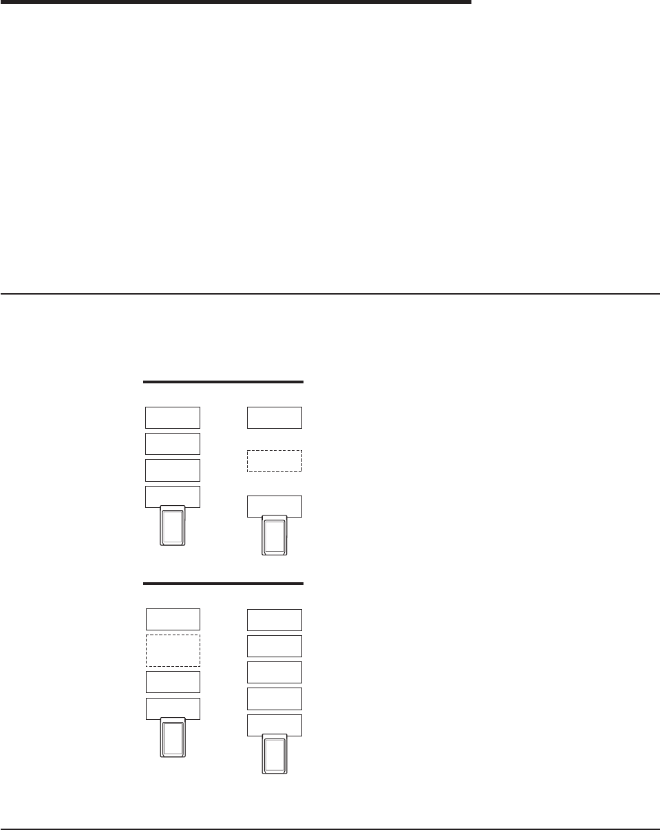
Chapter 6. Point Enablers and Card Services
Computers that support PC Cards have one or more PC Card slots, known as A, B,
C... or 1, 2, 3.... The slots are controlled by integrated circuit chips such as the
TI1130, TI1131, and TI1250 (Cardbus) controller chip sets, and many more.
In order for communications programs to use a PC Card, interface software of
some sort is needed. At present, several interfaces are available and each has its
advantages and disadvantages. The two most important interfaces are those
provided by Point Connectivity Enablers and Card Services; both are available
under DOS, but OS/2 requires you to use Card Services.
If you decide to use Card Services, you must install and enable it before running
LANAID.
A third type of interface is Socket Services.
Relationship Between the Interfaces
The following diagram shows how the interfaces relate to each other:
Credit Card Software Configurations
LAN Device
Driver
LAN Device
Driver
Card Services
Enabled
Point Connectivity
Enabled
Card Services
Enabler
Point
Enabler
Card
Services
Socket
Services
Socket
Controller
Socket
Controller
LAN Device
Driver
LAN Device
Driver
PCMCIA 2.1
Socket Services
Enabled
Card
Services
Socket
Services
Enabler
Socket
Services
Socket
Services
Socket
Controller
Socket
Controller
Point Connectivity Enablers
These are small programs that provide an interface directly to the PC Card
controller; therefore, they must be written to support a particular type of controller.
© Copyright IBM Corp. 1997, 1999 37

In the DOS environment only, you have the option of using these point connectivity
enablers
instead
of Card and Socket Services.
One point enabler is supplied for this PC Card:
POINTTR.EXE
For computers with Intel 32365SL PCMCIA controller chip sets or any
controller that is designed to be compatible. These include the IBM
ThinkPad, Toshiba 4500 and later, and many other makes.
Notes:
1. When using the point connectivity enabler, it is vitally important that you make
certain that the system resources used by the PC Card are different from and
do not conflict with the system resources and any other PC Cards installed in
your computer.
2. Windows NT currently uses a point enabler called PCMCIA.SYS, which
currently ships with Windows NT.
Advantage
vEnablers consume no memory — they remove themselves after configuring the
PC Card.
Disadvantages
vYou must specify the slot; the point enabler will enable only that slot. Therefore,
the PC Card must always be in a specific slot.
vIn some computers, the slot may not be switched off when the computer is in
suspend mode, so the PC Card will continue to consume power.
vWhen configuring two or more PC Cards, you must allocate memory and
interrupt resources manually under DOS.
Socket Services
This is a BIOS-type interface that provides a way to gain access to the PC Card
sockets (slots) of a computer. It identifies how many sockets your computer has and
detects the insertion or removal of a PC Card while the computer is switched on. It
has an interface to Card Services. Socket Services is part of the PCMCIA
Specification.
The Socket Services device driver is usually provided by the manufacturer of the
computer, because the driver must understand the computer’s BIOS and PCMCIA
controller.
Card Services
This is a software management interface that allows system resources (such as
memory, interrupts, slots, and I/O ports) to be allocated automatically when Socket
Services has detected that a PC Card has been inserted.
Client drivers call Card Services to allocate and de-allocate system resources.
When Socket Services detects an insertion or removal of a PC Card, it sends
notification to Card Services. Card Services then notifies its registered client drivers,
such as IBMTOKCS.OS2, that they should allocate or de-allocate resources.
38 Turbo 16/4 Token-Ring PC Card 2

If the installation program detects Card and Socket Services in your computer, it will
default to Autoset mode. Autoset mode allows your LAN driver to negotiate with
Card Services for memory space and interrupts. This helps to prevent conflicts with
other PC Cards that are installed in your computer; however, you will not know
exactly what memory addresses and interrupts have been given to you. It will
default to Autoset mode if the driver supports it.
Card Services requires Socket Services. The Card Services interface will usually be
provided with the operating system.
Advantages
vAbility to insert and remove PC Cards without computer reconfiguration and
without damaging the electrical contacts.
vAutomatic allocation of system resources.
vWhen used with your Token-Ring software in Autoset mode, automatic
configuration of your PC Card occurs.
Disadvantage
Stay-resident program that uses system memory. The amount varies according to
the type of PC Card support and the drivers used.
Card Services Enabler
If you want to use a Token-Ring device driver that does not have built-in Card
Services support on a system that uses Card Services, CS20TOK.EXE is supplied.
This program is a Card Services Enabler that uses Card and Socket Services to
configure the IBM Turbo 16/4 Token-Ring PC Card 2. As with other enablers, you
must specify the resources desired for the PC Card, and they must agree with the
settings of the Token-Ring device driver for the system to work correctly.
The DOS Card Services 2.00 interface enabler shipped on the CD-ROM is
CS20TOK.EXE.
CS20TOK.EXE
DOS Card Services 2.00 interface enabler. It uses the Card Services
interface to configure the socket and the PC Card. It is used when the
Token-Ring device driver is not a Card Services client driver and a Card
Services environment is desired. It works with DOS Card Services 2.00 and
higher.
Card and Socket Services versus Point Enablers
There is much debate about this. In principle, Card and Socket Services is the
better method of connection because it allows you to insert or remove PC Cards
from any socket, even while the computer is switched on; and it automatically
allocates resources like memory, I/O ports, interrupt levels, and slots.
Point Enablers, of which two are provided with the PC Card, are popular because
they remove themselves from memory after having been loaded—as opposed to
the 30–40 KB needed for Card and Socket Services.
For point enablers, you have to specify the slot in which a particular PC Card will
be used and you have to specify memory locations, interrupt levels, and other
Chapter 6. Point Enablers and Card Services 39

parameters. This is not difficult unless you use several PC Cards at different times,
in which case you need to make certain that what you specify does not conflict with
any other PC Cards installed in your computer.
Autoset Mode
Card and Socket Services turns out to be most helpful when you have a number of
PC Cards installed in your computer. If the installation program detects Card and
Socket Services in your computer, it will default to Autoset mode. Autoset mode
allows your LAN driver to negotiate with Card and Socket Services for memory
space and interrupts every time you switch on your computer. This helps to prevent
conflicts with other PC Cards that are installed in your computer; however, you will
not know exactly what memory addresses and interrupts you are using.
Using a Memory Manager in DOS Environments
If your computer comes with a memory manager preinstalled, or if you would like to
use one, you must configure your computer so that the memory manager does not
use the same memory as your PC Card. If you have more than one PC Card, you
must reserve the memory needed for all of them. One PC Card cannot use the
same memory ranges as another.
To determine whether or not your computer has a memory manager, edit your
CONFIG.SYS file and look for the memory manager driver name. For example,
when using EMM386, look for:
DEVICE=C:\DOS\EMM386.EXE ......
When using a memory manager, considerations for your PC Card environment
(Point Enabler or Card and Socket Services) are required. Listed here are
explanations for handling these environments with a memory manager. It is not
intended to be all-inclusive. To understand completely your memory manager and
your configuration files, refer to your computer’s operating system manual.
Memory Managers with Point Enablers
vTo prevent duplicate use of a memory location, the area used by your PC Card
must be excluded from the memory manager. To do this, you must edit your
CONFIG.SYS file. In certain environments, LANAID will add the exclude
statement automatically.
If you are using enhanced mode, 8 KB of memory must be excluded. If you are
using compatibility mode, 24 KB of memory must be excluded.
vFor the point enabler, the required exclusions are shown in the example below
(using EMM386, this is done using the X= parameter):
For enhanced mode:
DEVICE=C:\POINTTR.EXE SA RS=4 MMIO=D000 IRQ=9 SRAM=D000,4 WS=0
.
.
DEVICE=C:\DOS\HIMEM.SYS
.
.
DEVICE=C:\DOS\EMM386.EXE 1024 RAM X=D000-D1FF
For compatibility mode:
40 Turbo 16/4 Token-Ring PC Card 2
DEVICE=C:\POINTTR.EXE SA RS=4 MMIO=D000 IRQ=9 SRAM=D800,16 WS=0
.
.
DEVICE=C:\DOS\HIMEM.SYS
.
.
DEVICE=C:\DOS\EMM386.EXE 1024 RAM X=D000-D1FF X=D800-DBFF
Notice that the EMM386 line excludes the ranges that the POINTTR.EXE enabler
uses.
Memory Managers with Card and Socket Services
1. To prevent duplicate use of a memory location, the area used by your PC Card
must be excluded from the memory manager. To do this, you must edit your
CONFIG.SYS file. In certain environments, the installation program will add the
exclude statement automatically.
If you are in enhanced mode, 8 KB of the MMIO range must be excluded.
If you are in compatibility mode, 8 KB of the MMIO range (MMIO base address
default of D000) and 16 KB of the Shared RAM (SRAM) range (SRAM base
address default of D800) must be excluded.
In addition, Card Services needs at least 4 KB excluded for its use. Remember,
if you are using more than one PC Card, the memory locations for the other PC
Cards must also be excluded.
2. Card Services and memory managers typically do not talk to each other. You
must tell them what areas can be used. For example, with IBM Card Services
the /MA option is used to tell Card Services what memory range it can use for
PC Cards. It also uses some of this area for itself. That same /MA range must
be excluded from the memory manager line. This will prohibit the memory
manager from also using that same space.
For IBM CS, the /MA is used to specify the range of memory the PC Cards and
Card Services use. The parameter is added to the Resource Map Utility line in
your CONFIG.SYS. For example:
vUsing IBM Card Services:
On a computer using memory range C0000–CFFFF
DEVICE=C:\DOS\EMM386.EXE NOEMS X=C000-CFFF
.
.
DEVICE=C:\DOS\DICRMU02.SYS /MA=C000-CFFF
The Resource Map Utility driver name may be slightly different for the various
computers. Consult your operating manual.
vUsing Phoenix Card Services with the /ADDR option:
For some versions of Phoenix Card Services, the /ADDR parameter is used
to specify the 4-KB memory range used by Card Services. The memory
range chosen for the PC Cards must not conflict with this range. The /ADDR
parameter is placed on the Phoenix device driver line in the CONFIG.SYS
file. Consult your operation manual as to the version you have and whether
the /ADDR option is needed.
Note: The /ADDR needs only the starting address of the Card Services
memory area.
On a computer using memory range D0000–DFFFF
Chapter 6. Point Enablers and Card Services 41
DEVICE=C:\DOS\EMM386.EXE NOEMS X=D000-DFFF
.
.
DEVICE=C:\PCMPLUS\PCMCS.EXE /WAIT=12 /ADDR=D0 /IRQ=9
3. General Rules:
IBM Card Services
a. The memory area used by PC Cards must fall within the range specified
by /MA.
b. The memory area used by Card Services itself (4 KB) must be included
in the /MA range.
c. All of the /MA range must be excluded from your memory manager line.
Phoenix Card Services
a. The memory used by Card Services starting at the /ADDR address and
the memory used by the PC Card should be excluded from the memory
manager line.
b. If the /ADDR line is not used, the driver will use the first available
address on a 4-KB boundary for Card Services. The memory manager
line must exclude this area and the PC Card memory area.
Expanded Memory Specification
Expanded memory specification (EMS) requires 64 KB (one page frame) of
contiguous memory. This may cause you to move your PC Card memory range.
With EMM386 you set the page frame base address using the FRAME= option on
the memory manager line in the CONFIG.SYS. If the FRAME= option is not used,
EMM386 will find the first 64-KB block of contiguous memory. For example:
1. Using a point enabler with the PC Card at D0000–DBFFF, the C0000–CFFFF
range is free for the EMS page. A sample enhanced mode memory manager
line in your CONFIG.SYS is:
DEVICE=C:\DOS\EMM386.EXE RAM 1024 X=D000-D1FF FRAME=C000
Note: The Token-Ring PC Card uses D0000–D1FFF for 8-KB MMIO. The
FRAME= parameter sets the base address of the EMS page frame (the
page frame uses C0000–CFFFF). So, no PC Cards should be set to use
memory in the range C0000–CFFFF.
2. Using a point enabler with the PC Card at D0000–DBFFF, the C0000–CFFFF
range is free for the EMS page. A sample compatibility mode memory manager
line in your CONFIG.SYS is:
DEVICE=C:\DOS\EMM386.EXE RAM 1024 X=D000-D1FF
X=D800-DBFF FRAME=C000
Note: The Token-Ring PC Card uses D0000–D1FFF for 8-KB MMIO and
D8000–DBFFF for 16-KB SRAM. The FRAME= parameter sets the base
address of the EMS page frame (the page frame uses C0000–CFFFF).
So, no PC Cards should be set to use memory in the range
C0000–CFFFF.
3. Using IBM Card Services, you can set the /MA option such that a 64-KB block
is free for the EMS page frame. A sample memory manager line in your
CONFIG.SYS is:
DEVICE=C:\DOS\EMM386.EXE RAM 1024 X=D000-DBFF FRAME=C000
.
.
DEVICE=C:\DICRMU01.SYS /MA=D000-DBFF
42 Turbo 16/4 Token-Ring PC Card 2
Note: Because of the /MA option, IBM CS will use memory in the range
D0000–DBFFF only. The FRAME= parameter sets the base address of
the EMS page frame (the page frame uses C0000–CFFFF). So, no PC
Cards should be set to use memory in the range C0000–CFFFF.
Chapter 6. Point Enablers and Card Services 43
44 Turbo 16/4 Token-Ring PC Card 2

Appendix A. CD-ROM Content and Software Packages
The CD-ROM contains PC Card drivers, supporting applications, publications,
technical tips, and frequently asked questions related to the IBM Turbo 16/4
Token-Ring PC Card 2. A nagivational tool is provided to assist in accessing the
contents of the CD-ROM. This tool can be launched by opening the file
x:\startcd.htm (where x is the letter of your CD-ROM drive) in a Web browser.
Release date information can be obtained from the CD-ROM by selecting CD-ROM
— product support. However, the IBM Networking Web site might offer more
current information. If you have a Web connection, you can obtain the most current
drivers and information by selecting IBM Networking Web site — product
support.
v
User’s Guide
and
Token-Ring Adapter Features
in HTML and PDF format. See
“Product Documentation” on page 47.
vDevice Drivers that can be installed directly from the CD-ROM during the device
driver install process. They are located in the following directories:
Operating System Directory
Windows 9x \ (root)
Windows NT \ (root)
Windows 2000 \ (root)
Novell NetWare Server and Client \NOVELL\NETWARE
Novell NetWare DOS Requester (16–bit) \NOVELL\DOS
OS/2 \ (root)
DOS \DOS
Windows for Workgroups \WFW
vLAN Client files that can be installed directly from the CD-ROM during the LAN
Client installation process.
vSelf-expanding software package and diskette image files.
Software Packages
Table 6 lists packages that are available on the Web and on the CD-ROM. Table 7
on page 46 lists diskette images that are available on the Web and on the
CD-ROM. They can be obtained using the navigation tool already mentioned. Select
the Web link for the latest version of the file, or select the CD-ROM link to copy the
file directly from the CD-ROM. The files are located on the CD-ROM at x:\download
(where x is your drive letter).
Run the self-extracting package file to expand to a hard drive (or you can expand to
a diskette where noted with an asterisk (*)). The directory structure is maintained as
it exists on the CD-ROM.
Table 6. Software Packages
Package Description Executable
CD-ROM Complete CD-ROM content CDIMAGE.EXE
© Copyright IBM Corp. 1997, 1999 45

Table 6. Software Packages (continued)
Package Description Executable
Device Drivers (*) vDOS and Windows 3.1x (NDIS 2)
vNovell NetWare DOS Requester (16–bit)
vNovell NetWare Server and Client
vOS/2
vWindows 95/98/NT/2000
vWindows for Workgroups
vDOSNDIS.EXE
vDOSODI.EXE
vNETWARE.EXE
vOS2NDIS.EXE
vWIN32PCC.EXE
vWFWPKG.EXE
Documentation —
HTML and PDF vUser’s Guide
vToken-Ring Features
vUSERGUID.EXE
vFEATURES.EXE
IBM LAN Client IBM LAN Client — Complete package LCPKG.EXE
LAN Adapter
Management Agents vOS/2
vWindows NT and Windows 9x
vDMIOS2.EXE
vDMIWIN.EXE
Tivoli Management
Agents (*) vWindows 3.x
vWindows 9x
vWindows NT
vOS/2
vNetWare 3.x
vNetWare 4.x and 5.x
vTMAW3X.EXE
vTMAW9X.EXE
vTMAWNT.EXE
vTMAOS2.EXE
vTMANW3X.EXE
vTMANW4_5.EXE
LANAID (*) LAIDPKG.EXE
Diskette Images
Run these diskette image files to create diskettes. Each image file will create a
single diskette.
Table 7. Diskette Images
Image Description Executable
LAN Adapter
Management Agents vOS/2 — Diskette 1
vOS/2 — Diskette 2
vWindows 95/98/NT — Diskette 1
vWindows 95/98/NT — Diskette 2
vWindows 95/98/NT — Diskette 3
vDMIOS2A.EXE
vDMIOS2B.EXE
vDMIWINA.EXE
vDMIWINB.EXE
vDMIWINC.EXE
IBM LAN Client vIBM LAN Client — Diskette 1
vIBM LAN Client — Diskette 2
vIBM LAN Client — Diskette 3
vIBM LAN Client — Diskette 4
vLCDISK1.EXE
vLCDISK2.EXE
vLCDISK3.EXE
vLCDISK4.EXE
RUI vRemote Unattended Install diskette for
Windows 9x and Windows NT for NetBEUI
vRemote Unattended Install diskette for
Windows 9x and Windows NT for IP
vRUIPCCNB.EXE
vRUIPCCIP.EXE
46 Turbo 16/4 Token-Ring PC Card 2

Product Documentation
Complete product documentation is available for downloading from the CD-ROM
and the Web in both PDF and HTML formats. The HTML version can also be
viewed directly from your Web browser. Two documents are provided. The
User’s
Guide
includes hardware and software installation instructions, troubleshooting tips,
device driver parameters and error messages.
Token-Ring Adapter Features
provides detailed information about Remote Program Load, LAN Client, LAN
Adapter Management Agent, Route Switching, Class of Service, and the Tivoli
Management Agent.
To access the product documentation, insert the CD-ROM into the CD-ROM drive of
your computer and point your Web browser to x:\startcd.htm (where x is your
CD-ROM drive letter). Select IBM Networking Web Site or CD-ROM and then
Downloads. Select Target Operating System and then select the
User’s Guide
or
Token-Ring Adapter Features
. Select the package name that appears. You might be
prompted to select an ftp site from which to download the package. In the Save
as... dialog box, choose the path to the directory where you want to copy the
package file. Select OK to download the package file. Go to the directory where the
package was stored and run the package file to expand the files.
The
User’s Guide
in PDF format is stored in the file userguid.pdf.
Token-Ring
Adapter Features
in PDF format is stored in the file feature.pdf. The corresponding
HTML versions are in userguid.htm and feature.htm.
To view the documentation directly from the CD-ROM, insert the CD-ROM into the
CD-ROM drive of your computer and point your Web browser to x:\startcd.htm
(where x is your CD-ROM drive letter). Select CD-ROM — product support, select
your PC Card and then the documentation that you want to view.
Appendix A. CD-ROM Content and Software Packages 47
48 Turbo 16/4 Token-Ring PC Card 2

Appendix B. Problem Determination
Check this list of possible error conditions if problems occur.
1. Make sure that the PC Card is in the socket and that the cable is connected to
the PC Card.
2. You are using EMM386.EXE or another memory manager.
EMM386 is the source of many problems with PC Cards. The problem occurs
when EMM386.EXE and the LAN device driver are using the same memory.
This is called
memory contention
. The PC Card will not function correctly if this
contention occurs. If you are using Card Services, check to be sure that the
memory that Card Services controls is excluded by the memory manager. If you
are using a point enabler, be sure that the memory that you use is excluded by
the memory manager. As a quick test, you may want to comment out
EMM386.EXE in your CONFIG.SYS, reboot, and try the PC Card again.
If the PC Card functions, you will have to edit the EMM386.EXE command to
exclude some memory. The PC Card uses 8 KB of memory in two separate
areas. These memory areas may be consecutive. See Using a Memory
Manager in DOS Environments for more information.
3. You are using Card Services.
During reboot, you hear four alternating tones. This indicates that Card Services
was unable to give you one or more resources that your program requested.
Resources are I/O ports, interrupt level, and memory locations.
Note: The items in the following paragraph are performed by the installation
program.
If you are using the NDIS driver (IBMTOKCS.DOS), edit the PROTOCOL.INI file
and see whether you have specified a particular value for the interrupt level or
memory locations. This would be indicated by the keywords INTERRUPT=X,
MMIO=0xXXXX, or RAM=0xXXXX. If you are using the ODI driver
(TOKENCS.COM), edit the NET.CFG file and see whether you have specified a
particular value for the interrupt level or memory locations. This would be
indicated by the keywords INT X, MEM #1 XXXXX, or MEM #2 XXXXX.
These keywords specify a particular value for these parameters. If you find one
or more of these keywords, comment them out by placing a semicolon in front
of the keyword. Save the file and reboot your computer. If all three are
commented out or are not in PROTOCOL.INI or NET.CFG, the driver is in
Autoset mode and lets Card Services determine what values are used by the
driver. If you reboot and still receive the alternating beep alarm, there is a
problem with Card Services. Check your level of Card Services and ensure that
it is the latest available.
4. You are using a point enabler.
When you use a point enabler, it is essential that the I/O ports, interrupt,
memory areas, and slot number that are chosen by the enabler agree with what
the LAN device driver is expecting. Problems occur when the enabler has set
up certain resources and the LAN device driver is expecting others. Typically,
the LAN driver will not initialize. Look at the default values for the interrupt,
whether the PC Card is a primary or secondary PC Card (this affects the I/O
ports), and where the MMIO memory and the SRAM memory are located. Be
sure that the enabler settings and the settings of the LAN driver coincide. By the
use of parameters on the command line of the enabler and the parameters for
© Copyright IBM Corp. 1997, 1999 49

the LAN device driver (in PROTOCOL.INI, NET.CFG, or LSP.INI), you should be
able to configure your PC Card to function.
5. If you believe that you have a hardware problem with the PC Card, run the PC
Card diagnostics. See “Appendix C. Running the Diagnostics Program” on
page 81.
6. Check “Troubleshooting and Error Codes” if your computer displays an error
code. If you do not find your error code, use the following information to contact
IBM.
Questions, Problems?
World Wide Web
You can download the latest code from the World Wide Web.
On a Web browser:
www.networking.ibm.com/support
IBM Product Support
1-800-772-2227 IBM HelpCenter
1-800-565-3344 HelpPC (Canada)
1-800-237-5511 IBM Support Services
Troubleshooting and Error Codes
Novell NetWare Server Driver Messages
Error Code Explanation and Action
IBMTOKEN-xx-201 IBM Token-Ring Shared RAM Adapter, Version xxx
Explanation:
Information only.
User Action:
None.
IBMTOKEN-xx-202 The IBM Token-Ring Shared RAM Adapter UAA (BIA)
is
xxx
.
Explanation:
Information only.
User Action:
None.
IBMTOKEN-xx-203 The IBM Token-Ring Shared RAM Adapter is using an
LAA of
xxx
.
Explanation:
Information only.
User Action:
None.
50 Turbo 16/4 Token-Ring PC Card 2

Error Code Explanation and Action
IBMTOKEN-xx-204 Revision level
xxx
of the IBM Token-Ring Shared RAM
Adapter is incompatible with this driver version.
Explanation:
The Revision ID of the IBM Token-Ring
Shared RAM Adapter is not one that is
supported by this version of the device driver.
This correlation is enforced to ensure an
appropriate match between the adapter
hardware and the device driver software.
User Action:
Contact your customer service center for
assistance. You might need to upgrade your
adapter, use a different version of the device
driver, or both.
IBMTOKEN-xx-205 A device driver initialization error occurred (failure code
xxx
).
Explanation:
An unexpected error occurred during
initialization of the device driver.
User Action:
Properly shut down the computer and switch
off the power to the machine. Restart the
computer by switching it on again. If the error
persists, contact your customer service
center.
IBMTOKEN-xx-206 The configuration parameter
xxx
was specified
improperly. Its default value will be used.
Explanation:
The value of a configuration parameter was
improperly specified.
User Action:
Edit the configuration file (or rerun the
configuration program) to specify a value that
is of the correct type and within the allowed
range. Check the adapter installation
instructions for additional information.
Appendix B. Problem Determination 51

Error Code Explanation and Action
IBMTOKEN-xx-207 The configuration parameter values have forced the
internal data blocks to exceed the allowed limit.
Explanation:
The combination of configuration parameters
being used requires more than the 64–KB
memory area that is available for this adapter
instance to hold its internal control
information.
User Action:
Lower the value of the MaxTransmits or
MinRcvBuffs parameters from their current
setting to reduce the amount of control block
storage required by the device driver. Shut
down and restart to activate this configuration
change.
IBMTOKEN-xx-208 Unable to register interrupt level
xxx
for this adapter.
Explanation:
The hardware interrupt level assigned to this
adapter was not able to be registered (or
hooked
) by the device driver.
User Action:
Check the configuration of your computer,
looking for other devices that are assigned
the same interrupt level as this adapter. Try
removing the conflicting device from the
machine and restart the computer to see if
the problem goes away. If so, then determine
if he conflicting device can be left out of the
machine, or if the machine can be
reconfigured to resolve the conflict. Note that
in most machines, the BIOS assigns certain
system resources to the devices found in the
computer, including the interrupt level.
IBMTOKEN-xx-210 A hardware failure occurred while attempting to open
the adapter.
Explanation:
An adapter hardware error was detected
when opening the adapter for network
operation.
User Action:
Run the adapter diagnostics program to
isolate the problem and contact your
customer service center. If no problem was
identified by the diagnostics, check that the
cable is attached securely to both the adapter
and the network interface (wall plate). Turn
the computer off and then on again to restart
the machine. If the problem persists, contact
your customer service center.
52 Turbo 16/4 Token-Ring PC Card 2

Error Code Explanation and Action
IBMTOKEN-xx-211 A possible lobe wire failure was detected while
attempting to insert into the network.
Explanation:
The adapter is not correctly connected to the
Token-Ring network.
User Action:
Check that the cable is securely attached to
both the adapter and to the Token-Ring
network. You might need to contact your local
network administrator to ensure that the
cabling in the building is intact and that the
network concentrator to which you are
attached is operational. If the error persists,
try using a different cable.
IBMTOKEN-xx-212 A signal loss condition was detected while attempting
to insert into the network.
Explanation:
The Token-Ring network is not functioning
correctly.
User Action:
Contact your local network administrator to
determine the status of your network, or try
connecting again at a later time.
IBMTOKEN-xx-213 The lobe wire connected to the adapter is not attached
to the network.
Explanation:
The adapter is not correctly connected to the
Token-Ring network.
User Action:
Check that the cable is securely attached to
both the adapter and to the Token-Ring
network. You might need to contact your local
network administrator to ensure that the
cabling in the building is intact and that the
network concentrator to which you are
attached is operational. If the error persists,
try using a different cable.
Appendix B. Problem Determination 53

Error Code Explanation and Action
IBMTOKEN-xx-214 The configured data rate for the adapter does not
match that of the network.
Explanation:
The operational speed of the Token-Ring
network does not match the configured speed
of the adapter.
User Action:
Change the setting of the DataRate
configuration parameter to match the speed of
the network to which the adapter is attached.
Your local network administrator should be
able to tell you which speed to use. Setting
the DataRate parameter value to AUTO will
allow the adapter to automatically determine
the correct speed setting to use when
connecting to the network, provided that this
is not the only adapter active on the Token
Ring. Consult the adapter installation
instructions for additional information on
setting the DataRate parameter.
IBMTOKEN-xx-215 An adapter timeout occurred while attempting to insert
into the network.
Explanation:
The Token-Ring network is not functioning
correctly.
User Action:
Contact your local network administrator to
determine the status of your network, or try
connecting again at a later time.
IBMTOKEN-xx-216 A ring failure condition was detected while attempting
to insert into the network.
Explanation:
The Token-Ring network is not functioning
correctly.
User Action:
Contact your local network administrator to
determine the status of your network, or try
connecting again at a later time.
IBMTOKEN-xx-217 A ring beaconing condition was detected while
attempting to insert into the network.
Explanation:
The Token-Ring network is not functioning
correctly.
User Action:
Contact your local network administrator to
determine the status of your network, or try
connecting again at a later time.
54 Turbo 16/4 Token-Ring PC Card 2

Error Code Explanation and Action
IBMTOKEN-xx-218 A duplicate network address was detected while
attempting to insert into the network.
Explanation:
The address specified for the NetAddress
configuration parameter is being used by
another adapter (or ring station) on the
network.
User Action:
Modify the configuration file to change the
NetAddress parameter value being used for
this adapter, or remove the NetAddress
parameter to allow the adapter’s burned-in
address (universally administered address) to
be used. Contact your local network
administrator for assistance with choosing a
new NetAddress parameter value, or to
possibly have the conflicting adapter removed
from the same Token-Ring network as this
adapter.
IBMTOKEN-xx-219 A ring parameter failure occurred while attempting to
insert into the network.
Explanation:
The Token-Ring network is not functioning
correctly.
User Action:
Contact your local network administrator to
determine the status of your network, or try
connecting again at a later time.
IBMTOKEN-xx-220 The adapter was forced to remove itself while
attempting to insert into the network.
Explanation:
The Token-Ring network rejected the attempt
by this adapter to connect to it.
User Action:
Contact your local network administrator to
determine the status of your network, or try
connecting again at a later time.
Appendix B. Problem Determination 55

Error Code Explanation and Action
IBMTOKEN-xx-221 A hardware failure occurred while attempting to open
the adapter.
Explanation:
An adapter hardware error was detected
when opening the adapter for network
operation.
User Action:
Run the adapter diagnostics program to
isolate the problem and contact your
customer service center. If no problem was
identified by the diagnostics, check that the
cable is attached securely to both the adapter
and the network interface (wall plate). Turn
the computer off and then on again to restart
the machine. If the problem persists, contact
your customer service center.
IBMTOKEN-xx-222 A hardware failure occurred while attempting to open
the adapter.
Explanation:
A hardware error was detected when opening
the adapter for network operation.
User Action:
Run the adapter diagnostics program to
isolate the problem and contact your
customer service center. If no problem was
identified by the diagnostics, check that the
cable is attached securely to both the adapter
and the network interface (wall plate). Turn
the computer off and then on again to restart
the machine. If the problem persists, contact
your customer service center.
56 Turbo 16/4 Token-Ring PC Card 2

Error Code Explanation and Action
IBMTOKEN-xx-223 The adapter cannot be opened in AutoSense mode if it
is the only active station on the network.
Explanation:
The DataRate configuration parameter is set
to AUTO (which is also the default value if the
parameter is not specified), but the adapter is
the first station to open on the Token-Ring
network.
User Action:
This adapter is designed to not open onto the
attached Token-Ring network if it is configured
to use AutoSense detection and if it would
have been the first active ring station.
The possible remedies are to try connecting
again at a later time when at least one other
ring station is active on the network (such as
a network server), or to change the
configuration value so that the DataRate
parameter is set to a specific ring-speed value
of M16 or M4 and restart the computer.
Note that setting a specific value of M16 or
M4 for the DataRate parameter will cause this
adapter to establish the operational speed of
the Token-Ring network if it is still the first
active ring station, so consult with your local
network administrator if necessary.
Check the adapter installation instructions for
additional information on setting the DataRate
parameter.
IBMTOKEN-xx-224 Port
xxx
: The adapter attempted to perform a Remote
Program Load but failed monitor contention.
Explanation:
The adapter was opened as a Remote
Proram Load (RPL) client, but was unable to
locate an RPL server on the network.
User Action:
Make sure that there is an active Remote
Program Load server on the network and that
it is configured to recognize this adapter’s
network address.
Appendix B. Problem Determination 57

Error Code Explanation and Action
IBMTOKEN-xx-225 A network protocol error occurred while attempting to
operate the adapter in full duplex mode.
Explanation:
The adapter was unable to successfully
communicate with a Token-Ring switch when
attempting to open for full-duplex operation.
User Action:
Check that your full-duplex switch is
functioning correctly and that the adapter is
correctly connected to it. If this problem
persists, contact your customer service
center.
IBMTOKEN-xx-226 The adapter failed to open during an enhanced mode
open sequence.
Explanation:
The adapter failed during some phase of an
enhanced mode open sequence.
User Action:
Restart the computer. If the problem still
occurs run diagnostics. If the diagnostics
indicates that the adapter is not defective then
record this message number and contact your
customer service center.
IBMTOKEN-xx-227 The IBM Token-Ring Shared RAM Adapter opened at
xxx
Mbps, half duplex.
Explanation:
Information only.
User Action:
None.
IBMTOKEN-xx-228 The IBM Token-Ring Shared RAM Adapter opened at
xxx
Mbps, full-duplex.
Explanation:
Information only.
User Action:
None.
IBMTOKEN-xx-229 The adapter is configured for full duplex, but could only
be opened in half duplex mode.
Explanation:
Information only.
User Action:
None.
58 Turbo 16/4 Token-Ring PC Card 2

Error Code Explanation and Action
IBMTOKEN-xx-233 Adapter analysis code is
xxx
.
Explanation:
Information only.
User Action:
None.
IBMTOKEN-xx-234 Adapter full-duplex operation has now been activated.
Explanation:
Information only.
User Action:
None.
IBMTOKEN-xx-240 IBM Token-Ring Shared RAM Adapter
Explanation:
Information only.
User Action:
None.
IBMTOKEN-xx-301 ODI 3.3 and Above HSM
Explanation:
Information only.
User Action:
None.
IBMTOKEN-xx-304 Adapter is disconnected from the media.
Explanation:
The media network is not functioning
correctly.
User Action:
Check that the cable is securely attached to
both the adapter and the Token-Ring network.
Run adapter diagnostics if problems persist.
You might need to contact your local
administrator to ensure that the cabling in the
building is intact and that the network
concentrator to which you are attached is
operational. If the error persists, try using a
different cable.
IBMTOKEN-xx-305 Condition restored. The adapter is connected to the
media.
Explanation:
Information only.
User Action:
None.
Appendix B. Problem Determination 59

Error Code Explanation and Action
IBMTOKEN-xx-312 Insufficient memory for minimum number of receive
buffers.
Explanation:
The HSM driver was not able to allocate the
minimum number of receive buffers.
User Action:
Increase the number of buffers that the
server’s operating system can allocate by
editing the STARTUP.NCF file on the server.
Increase the Minimum Packet Receive Buffers
parameter in this file by the total number of
transmit (TxBuffers =) and receive (RxBuffers
=) that the HSM driver is using. Down and
restart the Novell NetWare server.
IBMTOKEN-xx-401 NetWare
xxx xxx
Explanation:
Information only.
User Action:
None.
IBMTOKEN-xx-402 Unable to find a supported board in this machine.
Explanation:
Information only.
User Action:
None.
IBMTOKEN-xx-403 Unable to acquire the configuration parameters for the
PCMCIA adapter.
Explanation:
Needed parameters have not been correctly
configured.
User Action:
Make sure that your computer is loading Card
and Socket Services. You must also be
loading the Token-Ring 16/4 PC Card
Connectivity Enabler (CS20TOK.EXE) in
CONFIG.SYS to configure your adapter.
Windows 95 and Windows 98
Windows 95 sometimes has trouble selecting available resources for the PC Card,
causing the PC Card not to function. If you find that your PC Card is not
functioning, follow this procedure.
1. Click Start.
2. Go to the Settings menu selection and click Control Panel.
3. Click System.
4. Click the Device Manager tab.
60 Turbo 16/4 Token-Ring PC Card 2
5. Go to the icon for Network Adapters. You might see a yellow or red circle with
an exclamation point inside beside an entry for the IBM Turbo 16/4 Token-Ring
PC Card 2. If you see this, click the entry. This will take you to the properties
dialog for the PC Card.
6. Click the Resources tab of the dialog box. There are three resources that must
be correct before the IBM Turbo 16/4 Token-Ring PC Card 2 will function
correctly. Acceptable values for the input/output range include any four
consecutive values beginning at 0300. The interrupt request value should be a
value between 3 and 15 that does not conflict with any other devices. The
memory range is often set incorrectly by Windows 95. It is recommended that
the memory range be set in the 000D0000 to 000DC000 in a non-conflicting
memory region. The memory range 000C0000 to 000CFFFF is often used for
video caches and Windows 95 does not always exclude memory regions that
are already in use.
7. If EMM386.EXE is in your CONFIG.SYS, comment it out.
Windows NT
Windows NT 3.51 and 4.0 use a point enabler called PCMCIA.SYS that is supplied
with Windows NT. PCMCIA.SYS configures the Intel compatible socket controller
with settings gleaned from the registry entry for the PC Card. Windows NT will
indicate resource conflicts only after an attempt is made to configure a device. As
when using a DOS enabler, you must manually choose your PC Card resources. By
looking at the event viewer in the administrative tools, you might find that there is
an I/O, IRQ, or memory conflict. A program called WINMSD is included with
Windows NT which allows you to see the resources of your machine and determine
if there are any conflicts. Make a note of your configured resources and compare
them to the settings indicated by WINMSD. Make corrections to your configuration
as needed. This is done by the following procedure:
1. Right-click Network Neighborhood.
2. Select Properties.
3. Select the Adapter tab.
4. Select IBM Turbo 16/4 Token-Ring PC Card 2 and click Properties.
You can now change your configuration as needed.
Windows 2000
Windows 2000 sometimes has trouble selecting available resources for the PC
Card, causing the PC Card not to function. If you find that your PC Card is not
functioning, follow this procedure:
1. From the Control Panel, double-click the System icon. Select the Hardware
tab, and click the Device Manager button.
2. From the Device Manager, look for a yellow or red circle with an exclamation
point beside an entry for the IBM Turbo 16/4 Token-Ring PC Card 2. If you see
this, then double-click the adapter. The properties dialog for the adapter will now
be displayed.
3. The device status window will tell you why the device is not functioning. You
might choose to try to resolve the problem yourself based on the problem
description, or Windows 2000 will help you solve the problem if you click the
Troubleshooter button.
Appendix B. Problem Determination 61

OS/2 NDIS Error Codes
The following sections provide messages that can be received from the NDIS driver
function. The messages are logged to a file. The NDIS driver signals the user when
a Card Services call fails; the error signal is an alternating beep. If you hear this
sound, and you are running OS/2, a problem is occurring during configuration of the
PC Card and you must review the LANTRAN.LOG file in your \IBMCOM
subdirectory to determine what is wrong. Depending on the error, you may see one
or more of the following error codes.
Error Code Explanation and Action
LTG0022E A failure during initialization of te IBMTOKCS device
driver has occurred. This is a generic
Explanation:
This is a generic initialization failure message.
If the IBMTOKCS device driver encounters
any errors during initialization, the specific
message related to the error will accompany
this generic message.
User Action:
Resolve the specific error that accompanies
this message. In addition, ensure that the
Protocol Manager device driver,
PROTMAN.OS2, is located in the \IBMCOM
directory, and that a DEVICE statement for
PROTMAN.OS2 exists in the CONFIG.SYS
file.
LTG0023I An unrecognized parameter was found in
PROTOCOL.INI.
Explanation:
The parameter displayed was found while the
installation program wa sprocessing the IBM
Token-Ring Network Driver section of
PROTOCOL.INI. The parameter is not valid.
User Action:
Correct the parameter or remove it from
PROTOCOL.INI.
LTG024I A value specified for a parameter in PROTOCOL.INI is
not valid.
Explanation:
The value provided for the parameter is not
the correct type or is not a valid value.
User Action:
Change the value for the parameter in
PROTOCOL.INI.
62 Turbo 16/4 Token-Ring PC Card 2

Error Code Explanation and Action
LTG0025I A configuration error was found in PROTOCOL.INI.
Explanation:
Conflicting parameter values were found while
the installation program was processing the
IBM Token-Ring Network Driver section of
PROTOCOL.INI.
User Action:
Examine the configuration parameters and
correct the conflicting values in
PROTOCOL.INI.
LTG0026I The PC Card is not responding or was not found.
Explanation:
One of the following conditions has caused
this error:
vThe logical primary or alternate setting in
the PROTOCOL.INI file does not map to
the physical primary or alternate setting.
vThe PC Card is not responding to a
request to start.
vThere is no physical PC Card in your
computer.
User Action:
If there is already a PC Card in this system,
check the logical primary or alternate setting.
Check the cable and ensure that the
connection to the token-ring network
addressable unit is functioning correctly. Then,
run the hardware diagnostics for the
token-ring PC Card to ensure that the PC
Card and options have been installed
correctly.
If there is no PC Card in your computer,
install a token-ring PC Card or remove the
device driver statement from the
CONFIG.SYS file.
LTG0027I The protocol manager could not be opened.
Explanation:
An unexpected error occurred when the
program attempted to open the protocol
manager.
User Action:
Check the drive and directory to ensure that
the protocol manager is located in the
specified path.
Appendix B. Problem Determination 63

Error Code Explanation and Action
LTG0029I The PC Card encountered a lobe wire fault.
Explanation:
The PC Card will be closed.
User Action:
Perform the following steps:
1. Check and secure all cable connections
between your PC Card and the
Multistation Access Unit (MSAU). Correct
any related problems and try the operation
again.
2. If there are no related problems, refer to
the documentation that was shipped with
your PC Card to run diagnostics; then, try
the operation again.
3. If the problem persists, print or save the
LANTRAN.LOG file and contact your LAN
administrator.
LTG0030I There are not adequate receive bufers for the PC Card
to open.
Explanation:
The requested DIR.OPEN.ADAPTER
paramaeter has not allowed enough receive
buffer space in the PC Card shared-RAM
area.
User Action:
Reduce the RAM requirements by
reconfiguring the parameters in
PROTOCOL.INI. The parameters that will
reduce the space requirements for the receive
buffer are the transmit buffers (if more than
one is specified).
LTG0032I An invalid node address error occurred when the
program attempted to open the PC Card.
Explanation:
The node address defined is not valid.
User Action:
Specify a valid node address. Refer to the
IBM Token-Ring Network Architecture
Reference
(SC30–3374) for node address
restrictions.
64 Turbo 16/4 Token-Ring PC Card 2

Error Code Explanation and Action
LTG0033I The receive buffer length defined is not valid.
Explanation:
The PC Card was not opened. The receive
buffer length defined in PROTOCOL.INI is not
valid. The value specified must be greater
than the allowable maximum, less than the
allowable minimum, or not a multiple of 8.
User Action:
Specify a valid receive buffer length.
LTG0034E The PC Card transmit buffer length defined is not
valid.
Explanation:
The PC Card was not opened. The PC Card
transmit buffer length defined in
PROTOCOL.INI is not valid. The value
specified must be greater than the allowable
maximum, less than the allowable minimum,
or not a multiple of 8.
User Action:
Specify a valid PC Card transmit buffer
length.
LTG0037I An unexpected error caused the Open Adapter
Command in the IBMTOKCS.OS2 device driver.
Explanation:
The PC Card was closed because of an
unexpected error condition.
User Action:
See the message log, LANTRAN.LOG, for
additional information about this error. The
error must be corrected before you can use
this PC Card.
Appendix B. Problem Determination 65

Error Code Explanation and Action
LTG0038I An auto-removal error has been detected.
Explanation:
The PC Card will be closed. The PC Card
has either detected a monitor contention
failure or received a beacon frame from the
ring. The problem might be that your PC Card
speed is different from the speed at which the
LAN is running.
User Action:
Perform the following steps:
1. Check and secure all cable connections
between your PC Card and the
multistation access unit (MSAU). Correct
any related problems and try the operation
again.
2. If there are no related problems, run the
diagnostics; then, try the operation again.
3. If the problem persists, print or save the
LANTRAN.LOG file and contact your LAN
administrator.
LTG0039I A remove medium access control (MAC) frame has
been received.
Explanation:
The PC Card will be closed. A command
forcing the PC Card to remove itself from the
ring has been received.
User Action:
Contact your LAN administrator to determine
why the REMOVE command was issued for
your computer.
LTG0041I An open error occurred during the lobe media test
phase.
Explanation:
The PC Card has detected a problem on your
local lobe between the PC Card and the
multistation access unit (MSAU).
User Action:
Perform the following steps:
1. Check and secure all cable connections
between your PC Card and the MSAU.
Correct any related problems and try the
operation again.
2. If there are no related problems, run the
diagnostics; then, try the operation again.
66 Turbo 16/4 Token-Ring PC Card 2

Error Code Explanation and Action
LTG0042I An open error occurred during the physical insertion
phase.
Explanation:
The PC Card has detected one of the
following open errors while trying to insert into
the LAN:
vRing failure
vRing beaconing
vTimeout
User Action:
Perform the following steps:
1. Check and secure all cable connections
between your PC Card and the
multistation access unit (MSAU). Correct
any related problems and try the operation
again.
2. If there are no related problems, run the
diagnostics; then, try the operation again.
LTG0043I An open error occurred during the address verification
phase.
Explanation:
The PC Card has detected one of the
following open errors during the address
verification phase of the PC Card open
process:
vSignal loss
vTimeout
vRing failure
vRing beaconing
vDuplicate node
vREMOVE command received
User Action:
Perform the following steps:
1. Check and secure all cable connections
between your PC Card and the
multistation access unit (MSAU). Correct
any related problems and try the operation
again.
2. If there are no related problems, run the
diagnostics; then, try the operation again.
Appendix B. Problem Determination 67

Error Code Explanation and Action
LTG0044I An open error occurred during the roll-call poll phase.
Explanation:
The PC Card has detected one of the
following open errors during the roll-call poll
phase of the PC Card open process:
vSignal loss
vTimeout
vRing failure
vRing beaconing
vREMOVE command received
User Action:
Perform the following steps:
1. Check and secure all cable connections
between your PC Card and the
multistation access unit (MSAU). Correct
any related problems and try the operation
again.
2. If there are no related problems, run the
diagnostics; then, try the operation again.
3. If the problem persists, print or save the
LANTRAN.LOG file and contact your LAN
administrator.
LTG0045I An open error occurred during the request parameter
phase.
Explanation:
The PC Card has detected one of the
following open errors during the request
parameter phase of the PC Card open
process:
vSignal loss
vTimeout
vRing failure
vRing beaconing
vParameter request
vREMOVE command received
User Action:
Perform the following steps:
1. Check and secure all cable connections
between your PC Card and the
multistation access unit (MSAU). Correct
any related problems and try the operation
again.
2. If there are no related problems, run the
diagnostics; then, try the operation again.
3. If the problem persists, print or save the
LANTRAN.LOG file and contact your LAN
administrator.
68 Turbo 16/4 Token-Ring PC Card 2

Error Code Explanation and Action
LTG0051I The open error type is function failure.
Explanation:
The PC Card has detected a lobe media
failure while trying to open the PC Card.
User Action:
Perform the following steps:
1. Check and secure all cable connections
between your PC Card and the
multistation access unit (MSAU). Correct
any related problems and try the operation
again.
2. If there are no related problems, run the
diagnostics; then try the operation again.
3. If the problem persists, print or save the
LANTRAN.LOG file and contact your LAN
administrator.
LTG0052I The open error type is signal loss.
Explanation:
The PC Card has detected a signal loss
failure while trying to open the PC Card.
User Action:
Perform the following steps:
1. Check and secure all cable connections
between your PC Card and the
multistation access unit (MSAU). Correct
any related problems and try the operation
again.
2. If there are no related problems, run the
diagnostics; then, try the operation again.
3. If the problem persists, print or save the
LANTRAN.LOG file and contact your LAN
administrator.
Appendix B. Problem Determination 69

Error Code Explanation and Action
LTG0055I The open error type is timeout.
Explanation:
The PC Card has detected an insertion timer
expiration while trying to open the PC Card.
This condition indicates that the ring might be
congested, experiencing a high bit-error rate,
or is losing an unusually high number of
tokens or frames.
User Action:
Perform the following steps:
1. Check and secure all cable connections
between your PC Card and the
multistation access unit (MSAU). Correct
any related problems and try the operation
again.
2. If there are no related problems, run the
diagnostics; then, try the operation again.
3. If the problem persists, print or save the
LANTRAN.LOG file and contact your LAN
administrator.
LTG0056I The open error type is ring failure.
Explanation:
The PC Card has detected a ring failure while
trying to open the PC Card.
User Action:
Perform the following steps:
1. Check and secure all cable connections
between your PC Card and the
multistation access unit (MSAU). Correct
any related problems and try the operation
again.
2. If there are no related problems, run the
diagnostics; then, try the operation again.
3. If the problem persists, print or save the
LANTRAN.LOG file and contact your LAN
administrator.
70 Turbo 16/4 Token-Ring PC Card 2

Error Code Explanation and Action
LTG0057I The open error type is ring beaconing.
Explanation:
The PC Card has detected a monitor
contention failure or has received a beacon
frame from the ring while trying to open the
PC Card.
User Action:
Perform the following steps:
1. Check and secure all cable connecetions
between your PC Card and the
multistation access unit (MSAU). Correct
any related problems and try the operation
again.
2. If there are no related problems, run the
diagnostics; then, try the operation again.
3. If the problem persists, print or save the
LANTRAN.LOG file and contact your LAN
administrator.
LTG0058I The open error type is duplicate node address.
Explanation:
The PC Card has detected that another
station on the ring has a PC Card address
equal to the address specified for your PC
Card.
User Action:
Note the identification number of this
message and then contact your LAN
administrator.
LTG0059I The open error type is parameter request.
Explanation:
The PC Card has detected a parameter
request error while trying to open the PC
Card.
User Action:
Perform the following steps:
1. Check and secure all cable connections
between your PC Card and the
multistation access unit (MSAU). Correct
any related problems and try the operation
again.
2. If there are no related problems, refer to
the documentation that was shipped with
your PC Card to run the diagnostics; then,
try the operation again.
3. If the problem persists, print or save the
LANTRAN.LOG file and contact your LAN
administrator.
Appendix B. Problem Determination 71

Error Code Explanation and Action
LTG0060I The open error type is REMOVE received.
Explanation:
While attempting to insert into the ring, your
computer received a command forcing this
PC Card to remove from the ring.
User Action:
Contact your LAN administrator to determine
why the REMOVE command was issued for
your computer.
LTG0063I Your computer is the first attempting to insert onto the
ring in AUTORINGSPEED mode.
Explanation:
User Action:
Either remove the AUTORINGSPEED
keyword from PROTOCOL.INI or make sure
that another computer is on the network and
has set the ring speed. If the problem
persists, print or save the LANTRAN.LOG file
and contact your LAN administrator.
LTG0064I Physical insertion of your computer onto the ring failed.
Explanation:
User Action:
Check the PC Card configuration and retry
the open request. If the problem persists,
refer to the documentation that was shipped
with your PC Card to run diagnostics; then,
try the operation again.
LTG0070I A problem was detected on microcode level 00 00 00
C2 45 50.
Explanation:
User Action:
Request and install engineering change
ECA0066, P/N 92F9122, on your system, or
use the configuration feature of the LAN
Adapter Protocol Support installation program
to change the value for the number of
transmit buffers to be greater than 1.
LTG0083E Token-Ring Credit Card Request I/O failed.
Explanation:
Card Services would not give IBMTOKCS
access to the I/O ports it requested.
User Action:
Make sure that no other PC Cards are using
the range of I/O ports that the adapter needs.
For a primary PC Card the range is A20–A23.
For a secondary PC Card the range is
A24–A27.
72 Turbo 16/4 Token-Ring PC Card 2

Error Code Explanation and Action
LTG0084E Token-Ring Credit Card Request IRQ failed.
Explanation:
Card Services would not give IBMTOKCS
access to the interrupt request (IRQ) line it
requested.
User Action:
Make sure that no other PC Cards are using
the IRQ requested. IBMTOKCS defaults to
IRQ 9. To change the IRQ that IBMTOKCS
uses, add the line INTERRUPT=X to your
PROTOCOL.INI file. X can be any one of the
following values: 3, 4, 5, 7, 9, 10, or 11. The
IRQ chosen should not be used by any other
device.
LTG0085E Token-Ring Credit Card RAM Request Window failed.
Explanation:
Card Services would not give IBMTOKCS
access to the memory window that it
requested.
User Action:
Make sure that no other PC Cards are using
the memory window requested. IBMTOKCS
defaults the MMIO memory window to CC00
for the primary PC Card ot DC00 for the
alternate PC Card. It also defaults the SRAM
memory window to D800 for the primary PC
Card or D400 for the alternate PC Card. To
change the MMIO memory window, add the
line MMIO=XXXX to your PROTOCOL.INI file.
XXXX can be any unused 8–KB, 16–KB,
32–KB, or 64–KB region in the range
C000–DC00. You might also have to asjust
the RAMSIZE keyword accordingly.
LTG0086E Token-Ring Credit Card Request Configuration failed.
Explanation:
Card Services would not give IBMTOKCS the
configuration that it requested.
User Action:
Try a different interrupt line by using the
INTERRUPT=X statement in your
PROTOCOL.INI file. X can be any unused
interrupt line in the range 3–15.
Appendix B. Problem Determination 73

Error Code Explanation and Action
LTG0087E Token-Ring Credit Card RAM MapMemPage failed.
Explanation:
Card Services would not map the
shared-RAM memory on the PC Card to the
required memory window.
User Action:
Try changing the memory window.
IBMTOKCS defaults the MMIO memory
window to CC00 for the primary PC Card or
DC00 for the alternate PC Card. It also
defaults the SRAM memory window to D800
for the primary PC Card or D400 for the
alternate PC Card. To change the MMIO
meory window, add the line MMIO=XXXX to
your PROTOCOL.INI file. XXXX can be any
unused 8–KB region in the range
C000–DE00. To change the SRAM memory
window, add the line RAM=XXXX to your
PROTOCOL.INI file. XXXX can be any
unused 8–KB, 16–KB, 32–KB, or 64–KB
region in the range C000–DC00. You might
also have to adjust the RAMSIZE keyword
accordingly.
LTG0090E Token-Ring Credit Card Register Client failed.
Explanation:
Card Services would not register the PC Card
callback handler.
User Action:
Make sure that you have Card Services 2.0
(PCMCIA.SYS) correctly installed.
LTG0091E Card Services could not be found.
Explanation:
User Action:
Add the appropriate statements to your
CONFIG.SYS file so that Card Services will
be installed.
74 Turbo 16/4 Token-Ring PC Card 2

Error Code Explanation and Action
LTG0093E No sockets were found by Card Services.
Explanation:
The Card Services function
GetCardServicesInfo reported that there are
no sockets in your computer. This can be for
any of the following reasons:
1. Socket Services is not installed or is
installed incorrectly.
2. There are no physical sockets on your
computer.
3. No PC Card with sockets is installed or is
installed incorrectly.
User Action:
Perform the following steps:
1. Make sure that you have Socket Services
installed correctly.
2. Make sure that your computer has
physical sockets.
3. Make sure that you have installed the PC
Card correctly.
LTG0094I A Token-Ring Auto 16/4 Credit Card Adapter was not
found in any socket in your computer.
Explanation:
User Action:
Insert the PC Card in a socket.
LTG0095E A NETADDRESS must be specified to boot without the
PC Card present in a socket.
Explanation:
You attempted to boot your computer without
a Token-Ring Auto 16/4 Credit Card Adapter
inserted in a socket and without a
NETADDRESS.
User Action:
Either insert the PC Card in a socket and
reboot your computer or add the
NETADDRESS= parameter to
PROTOCOL.INI and reboot your computer.
By adding the NETADDRESS parameter you
can insert the Token-Ring Auto 16/4 Credit
Card Adapter after the reboot. Make sure that
the address you use is either a locally
administered address or the universally
administered address on your PC Card. To
find out your universally administered
address, run the diagnostics program that is
on the diskettes that came with your adapter.
Appendix B. Problem Determination 75

Error Code Explanation and Action
LTG0097E Token-Ring Credit Card MMIO RequestWindow failed.
Explanation:
Card Services would not give IBMTOKCS
access to the MMIO memory window it
requested.
User Action:
Make sure that no other PC Cards are using
the memory window requested. IBMTOKCS
defaults the MMIO memory window to CC00
for the primary PC Card or DC00 for the
alternate PC Card. To change the MMIO
memory window, add the line MMIO=XXXX to
your PROTOCOL.INI file. XXXX can be any
unused 8–KB region in the range
C000–DC00.
LTG0098E Token-Ring Credit Card MMIO MapMemPage failed.
Explanation:
Card Services would not map the MMIO
memory on the PC Card to the requested
memory window.
User Action:
Try changing the MMIO memory window.
IBMTOKCS defaults the MMIO memory
window to CC00 for the primary PC Card or
DC00 for the alternate PC Card. To change
the MMIO memory window, add the line
MMIO=XXXX to your PROTOCOL.INI file.
XXXX can be any unused 8–KB region in the
range C000–DC00.
LTG0099E PROTOCOL.INI did not have a section with a
DriverName=IBMTCS$ keyword.
Explanation:
A common cause of this is not using LAPS to
install new drivers.
User Action:
Use LAPS to install the new PC Card
Token-Ring Driver.
DOS NDIS Error Codes
Error Code Explanation and Action
LTG0022E A failure during initialization of the IBMTOKCS device driver has
occurred. This is a generic initialization failure message. If the
IBMTOKCS device driver encounters any errors during initialization,
the specific message related to the error will accompany this generic
message.
Resolve the specific error message that accompanies this message.
In addition, ensure that the Protocol Manager device driver,
PROTMAN.DOS, exists, and that a DEVICE statement for it exists in
the CONFIG.SYS file.
76 Turbo 16/4 Token-Ring PC Card 2

ODI 16-bit Client Error Codes
Error Code Explanation and Action
TOKENCS-DOS-32 Driver registered as a NESL Suspend Class producer.
Explanation:
This is an informational only message.
User Action:
No action is required.
TOKENCS-DOS-33 Driver registered as a NESL Resume Class producer.
Explanation:
This is an informational only message.
User Action:
No action is required.
TOKENCS-DOS-34 Driver registered as a NESL Service Change Class
producer.
Explanation:
This is an informational only message.
User Action:
No action is required.
TOKENCS-DOS-36 NetWare Event Service Layer (NESL) is Loaded.
Explanation:
This is an informational only message.
User Action:
No action is required.
TOKENCS-DOS-50 The board cannot be found or the cable is not
attached.
Explanation:
The PC Card has not been inserted in the
PCMCIA socket.
User Action:
Insert your PC Card in the socket and try
again.
TOKENCS-DOS-204 The shared RAM is on incorrect boundary.
Explanation:
User Action:
Change the Shared RAM base address and
place it on a 16–KB boundary (C0000,
C4000, C8000, CC000, D0000, D4000,
D8000, DC000).
Appendix B. Problem Determination 77

Error Code Explanation and Action
TOKENCS-DOS-205 The PC Card did not reset during initialization.
Explanation:
During initialization, no interrupt occurred.
User Action:
This can happen if you are using an enabler
and it is setting an interrupt level that is
different from the interrupt level
TOKENCS.COM is using. Check to make
sure that both interrupts are the same.
TOKENCS-DOS-206 An interrupt failed to occur during initialization.
Explanation:
During initialization, no interrupt occurred.
User Action:
This can happen if you are using an enabler
and it is setting an interrupt level that is
different from the interrupt level
TOKENCS.COM is using. Check to make
sure that both interrupts are the same.
TOKENCS-DOS-226 The ROM and shared RAM address ranges overlap.
Explanation:
The ROM and RAM memory areas are
overlapping.
User Action:
Check the settings in NET.CFG for MEM #1
and MEM #2. MEM #1 determines the ROM
(MMIO) base address. MEM #2 determines
the Shared RAM base address. If you are
using an enabler, check where it is placing
the ROM (MMIO) and the RAM address.
ROM is 8 KB in size. RAM is usually 16 KB in
size.
TOKENCS-DOS-228 The MAX FRAME SIZE in NET.CFG file is too large
(Max=17 960)
Explanation:
The maximum frame size has been
exceeded.
User Action:
Change the maximum frame size to a valid
value.
TOKENCS-DOS-229 The MAX FRAME SIZE in NET.CFG file is too small
(Min=632).
Explanation:
The maximum frame size is too small.
User Action:
Increase the maximum frame size to a valid
value.
78 Turbo 16/4 Token-Ring PC Card 2

Error Code Explanation and Action
TOKENCS-DOS-230 The specified MAX FRAME SIZE in NET.CFG is not a
multiple of 8.
Explanation:
The maximum frame size has been set to a
value that is not valid.
User Action:
Change the MAX FRAME SIZE to a multiple
of 8.
TOKENCS-DOS-231 The MAX FRAME SIZE in NET.CFG is too big for this
PC Card.
Explanation:
The maximum value at this speed for this PC
Card is
xx
.
User Action:
Change the MAX FRAME SIZE to a valid
value.
TOKENCS-DOS-233 Card Services could not be found.
Explanation:
TOKENCS.COM could not find Card Services.
User Action:
Check your CONFIG.SYS and ensure that
Card Services is loading. If Card Services
support is not wanted, take the PCMCIA
keyword out of NET.CFG.
TOKENCS-DOS-235 A Card Services error has occurred.
Explanation:
You have heard an alternating tone and this
message is posted to the panel. This
indicates that Card Services was unable to
provide the resources requested.
User Action:
Check your NET.CFG parameters INT, MEM
#1, MEM #2. If they are not in NET.CFG,
Card Services has a problem. If they are
specified in NET.CFG, comment (REM) them
out and try again.
TOKENCS-DOS-237 PCMCIA Token-Ring MLID Loaded, but PC Card is not
in socket.
Explanation:
This is an informational only message.
User Action:
No action is required.
Appendix B. Problem Determination 79

Error Code Explanation and Action
TOKENCS-DOS-246 The DATA RATE specified in NET.CFG must be either
4 or 16 Mbps.
Explanation:
You have specified an incorrect ring speed. It
must be either 4 or 16 Mbps. The DATA
RATE keyword is used to set the speed.
User Action:
(no message) Please insert an IBM Turbo 16/4 Token-Ring PC Card
2 or press Esc to avoid loading the driver.
Explanation:
This message occurs when you have not
inserted an IBM Turbo 16/4 Token-Ring PC
Card 2 in the computer and have started
TOKENCS.COM.
User Action:
Insert an IBM Turbo 16/4 Token-Ring PC
Card 2 at this time or press Esc to leave.
80 Turbo 16/4 Token-Ring PC Card 2

Appendix C. Running the Diagnostics Program
Important
To avoid potentially erroneous results, you should always perform a power-on
reboot of your computer before running the diagnostics.
The Diagnostics and LANAIDC diskette must be created before you run the
following procedure. See “Appendix A. CD-ROM Content and Software Packages”
on page 45 for instructions.
Use the diagnostics program on the Diagnostics and LANAIDC diskette to test the
hardware components of the PC Card. Different operating systems will show
resources differently.
The diagnostics program performs a series of tests and displays the results of each
one by showing success or failure. An error during any test will end the test in
progress and display an error message and error code. See the following tables for
a description of error codes and recommended actions.
Note: The testing process might run as long as 3 minutes and can be exited at any
time by pressing Enter or by removing the Diagnostics and LANAIDC
diskette and pressing Esc. Pressing Esc will cause the computer to reboot.
Pressing Enter will end the test in progress and allow the user to select
another test option.
1. Insert the Diagnostics and LANAIDC diskette.
2. Switch ON the power to the computer.
3. At the DOS Menu, select 2, IBM Turbo 16/4 Token-Ring PC Card
Extended Diagnostics.
4. Follow the instructions as they appear. You will be prompted to select a
test option. See “Test Options” for descriptions.
Test Options
There are two test options: the wrap test and the on-ring test. The on-ring test will
not function on a 4–MB token-ring network.
The wrap test ensures that the adapter and cable hardware are functioning
properly. For this test, connect the adapter and cable to the network to perform a
wrap test through the hub or concentrator, or insert a wrap plug (no wrap plug is
required if you have an STP cable connection) to help isolate a failure to the
adapter, the cable, or the wiring to the hub or concentrator.
Diagnostics Error Codes and Suggested Actions
Initialization Error Codes
Failure during adapter initialization usually indicates a hardware error on the PC
card. Reboot your computer using the diagnostics on the Diagnostics and LANAIDC
diskette, and run the diagnostic program again. If the PC card continues to fail,
replace it and the cable.
© Copyright IBM Corp. 1997, 1999 81
One of the following codes will be shown to indicate the results of the initialization
test. The error codes are displayed in hexadecimal format and represent the
BRING_UP_CODE set by the adapter.
0000 Initialization success
0014 No microcode
0020 Diagnostics could not be executed
0022 ROM diagnostics failed
0024 Shared RAM diagnostics failed
0026 Processor instruction test failed
0028 Processor interrupt test failed
002A Shared RAM interface register diagnostics failed
002C Protocol-handler diagnostics failed
0040 PC Card’s programmable timer for the computer failed (set by the
microcode)
0042 Cannot write to shared RAM (set by microcode)
0044 Reading from shared RAM read-only area caused an incorrect error
indication (interrupt)
0046 Writing into shared RAM read-only area did not cause an error indication
(interrupt)
0048 Initialization timed out
Open Errors
Failure during the adapter open test might indicate that the adapter is not properly
configured to run on the network it is trying to open onto or that the adapter is not
properly configured for the system. The open test provides a return code and an
open error code. If the return code is 07, then see “Open Error Codes” on page 83
for a more accurate description of the failure and suggested actions. If the return
code is a value other than 00 or 07, problem determination of the PC Card and the
diagnostics is necessary. Record the error and contact your network administrator.
00 Open completed successfully
01 Incorrect command code
03 Adapter open, should be closed
05 Required parameters not provided
07 Command cancelled, unrecoverable failure (see open error codes to isolate
problem)
30 Inadequate receive buffers
32 Incorrect MAC address
33 Incorrect adapter receive buffer length
34 Incorrect adapter transmit buffer length
82 Turbo 16/4 Token-Ring PC Card 2

Open Error Codes
If the open provides a return code of 7, there will be a corresponding error code.
The open errors are returned in 2 bytes. The high-order byte is always 0 and the
low-order byte contains the following information:
1. The phase of testing in which the error was encountered is in the high-order
nibble (half-byte) of the low-order byte.
2. The error condition is in the low order nibble of the low-order byte.
Phases
Value Meaning
1n Lobe media test
2n Physical insertion
3n Address verification
4n Roll call poll (neighbor notification)
5n Request parameters
Errors
Value Meaning
n1 Function failure
n2 Signal loss
n3 Reserved
n4 Frequency error (see note)
n5 Time-out
n6 Ring failure
n7 Ring beaconing
n8 Duplicate node address
n9 Parameter request—retry count exceeded
nA Remove received
nB IMPL force received
nC Duplicate modifier
nD No monitor detected
nE Monitor contention failed for RPL
Suggested Actions in Response to Open Errors
When the following phase-error combination values are presented, they are the
result of certain specific occurrences. Explanation of the occurrences follows with
recommended actions listed. Table 8 on page 86 lists the recommended actions for
both the application program and the computer operator.
Error Code Explanation Action
11 Lobe Media, Function Failure: The testing of the lobe
between the PC Card and the access unit has been
unsuccessful because the lobe has a bit-error rate
that is too high, or the PC Card cannot receive
successfully.
1, 3, and 5
Appendix C. Running the Diagnostics Program 83

Error Code Explanation Action
24 Physical Insertion, Frequency Error: The PC Card has
detected that the ring is operating at a speed other
than the speed at which it was inserting.
2
26 Physical Insertion, Ring Failure: The PC Card, acting
as an active monitor, was unable to complete the ring
purge function successfully. This indicates that an
error condition has occurred since the successful
completion of monitor contention (claim token), when
this PC Card became the active monitor.
1 and 2a
27 Physical Insertion, Ring Beaconing: The PC Card has
detected one of the following conditions:
vThe PC Card tried to insert on a ring that was
operating at a different data rate.
vA monitor contention (claim token) failure occurred.
vThe PC Card received a beacon MAC frame from
the ring.
1, 2, and 2b
2A Physical Insertion, Remove Received: The PC Card
has received a remove ring station MAC frame,
indicating that a network management function has
directed this PC Card to get off the ring.
2a and 4
2D Physical Insertion, No Monitor Detected: RPL station
is the first station attempting to insert onto the ring. 1 and 2a
2E Physical Insertion, Monitor Contention Failed for RPL:
Physical insertion failure of RPL station. 2
32 Address Verification, Signal Loss: The PC Card has
detected a 250-ms signal loss (receiver cannot
recognize signal), indicating that an error condition
has occurred since the PC Card successfully
completed the ring signal recognition phase of the
open operation.
1 and 2a
35 Address Verification, Time-out: The insertion timer
expired before this function was completed, indicating
that the ring can be congested, experiencing a high
bit-error rate, or losing an abnormally high number of
tokens or frames, thus preventing successful Address
Verification MAC frame transmissions.
1 and 2a
36 Address Verification, Ring Failure: The PC Card,
acting as an active monitor, was unable to complete
the ring purge function successfully. This indicates
that an error condition has occurred since the
successful completion of monitor contention (claim
token), when this PC Card became the active monitor.
1 and 2a
37 Address Verification, Ring Beaconing: The PC Card
has either detected a monitor contention (claim token)
failure or received a beacon MAC frame from the ring.
1 and 2b
38 Address Verification, Duplicate Node Address: The PC
Card has detected that another station on the ring has
a PC Card address that is the same as the PC card
address being tested.
4
3A Address Verification, Remove Received: The PC Card
has received a remove ring station MAC frame,
indicating that a network management function has
directed this specific address to get off the ring.
2a and 4
84 Turbo 16/4 Token-Ring PC Card 2

Error Code Explanation Action
42 Ring Poll, Signal Loss: The PC Card has detected a
250-ms signal loss (receiver cannot recognize signal)
indicating that an error condition has occurred since
the PC Card successfully completed the ring signal
recognition phase of the open operation.
1 and 2a
45 Ring Poll, Time-out: The insertion timer expired before
this function was completed, indicating that the ring
can be congested, experiencing a high bit-error rate,
or losing an abnormally high number of tokens or
frames. This prevents the PC Card’s successful
reception of either the ring poll request or response
MAC frame, or transmission of the required ring poll
response MAC frame.
1 and 2a
46 Ring Poll, Ring Failure: The PC Card, acting as an
active monitor, was unable to complete the ring purge
function successfully. This indicates that an error
condition has occurred since the successful
completion of monitor contention (claim token), when
this PC Card became the active monitor.
1 and 2a
47 Ring Poll, Ring Beaconing: The PC Card has either
detected a monitor contention (claim token) failure or
received a beacon MAC frame from the ring.
1 and 2b
4A Ring Poll, Remove Received: The PC Card has
received a remove ring station MAC frame, indicating
that a network management function has directed this
PC Card to get off the ring.
2a and 4
55 Request Parameters, Time-out: The insertion timer
expired before this function was completed, indicating
that the ring can be congested, experiencing a high
bit-error rate, or losing an abnormally high number of
tokens or frames. This prevents successful
transmission of the request parameter MAC frame or
reception of either the set parameter 1 or set
parameter 2 MAC frame (required response to the PC
Card’s request).
1 and 2a
56 Request Parameters, Ring Failure: The PC Card,
acting as an active monitor, was unable to complete
the ring purge function successfully. This indicates
that an error condition has occurred since the
successful completion of monitor contention (when
this PC Card became the active monitor).
1 and 2a
57 Request Parameters, Ring Beaconing: The PC Card
has received a beacon MAC frame from the ring. 1 and 2b
59 Request Parameters, Parameter Request - Retry
Count Exceeded: The PC Card has detected that the
ring parameter server is present on the ring but that
the required response (set parameter 1 or set
parameter 2 MAC frame) was not received in the
allotted time. This indicates that the ring can be
congested, experiencing a high bit-error rate, or losing
an abnormally high number of tokens or frames.
1 and 2a
5A Request Parameters, Remove Received: The PC
Card has received a remove ring station MAC frame,
indicating that a network management function has
directed this PC Card to get off the ring.
2a and 4
Appendix C. Running the Diagnostics Program 85

Recommended Actions Table
Table 8. Recommended Actions
Number Description
1 After delaying at least 30 seconds, retry the open two times,
inserting the same delay between each try.
2 After delaying at least 30 seconds, check the PC Card configuration
(especially the PC Card data rate) and retry the open.
2a If this error persists, contact your network administrator for
assistance and provide Open Error information.
2b If this error persists, contact your network administrator for
assistance.
3 Contact your network administrator for assistance and provide Open
Error information.
4 Contact your network administrator for assistance and provide Node
Address information, and try attaching to the ring after 6 minutes.
5 If this error persists, problem determination of the PC Card or lobe is
necessary. Contact your network administrator for problem
determination assistance.
Transmit Error Codes
If you experience time-out errors during the on-ring test, try running the wrap test in
the diagnostics. If the wrap test is completed successfully, but the on-ring test fails,
it might indicate problems on the Token-Ring network that the adapter is opening
onto during the on-ring test.
For any other errors, ensure that the adapter and cabling are properly connected,
and retry the test. If the adapter continues to fail, record the error and contact your
network administrator.
01 Unrecognized command code
08 Unauthorized access priority
22 Error on frame transmission, examine STRIPPED_FS
23 Error on frame transmit or strip process
24 Unauthorized MAC frame
25 Maximum commands exceeded
26 Correlator not acceptable
27 Link not transmitting I frames, status changed from link open
28 Transmit frame length not acceptable
29 Link retransmission in process, buffers free
40 Station ID not acceptable
41 Protocol error, link not in acceptable state for command
86 Turbo 16/4 Token-Ring PC Card 2

Appendix D. LANAIDC Parameter Information
LANAIDC is the command line version of LANAID. It contains all of the function of
LANAID without the graphical user interface. Its primary intended users are LAN
administrators and other users who want to duplicate a certain IBM Turbo 16/4
Token-Ring PC Card 2 configuration on multiple computers.
The LANAIDC program is in the same directory on your hard drive where LANAID
was installed (see “Installing LANAID” on page 33). Typing LANAIDC without
parameters will cause LANAIDC to use a configuration file called LANAIDC.CFG to
configure the PC Card. This file is created by the graphical LANAID program after it
successfully completes a PC Card configuration. See “Using LANAIDC to Duplicate
Configurations” for more information about using the configuration file.
Type lanaidc /h to show the long help list for all the configuration parameters, and
type lanaidc /? to show the short help list. Also, you can choose LANAIDC from the
menu that is displayed when the computer is booted from the Diagnostic and
LANAIDC diskette. Using this method to configure the PC Card with LANAIDC is
not recommended, however, since correct configuration depends on the computer
being booted in the environment under which the PC Card will run.
Using LANAIDC to Duplicate Configurations
In order to take a configuration performed by LANAID on one computer and
duplicate it on others, follow these steps:
1. Boot the computer in the same environment that the PC Card will use.
2. If LANAID has not yet been installed, install it according to the instructions. See
Chapter 5. LANAID.
3. Use LANAID to configure that computer for the PC Card, and exit LANAID.
During configuration, LANAID creates a file called LANAIDC.CFG that contains
all of the information required to recreate the same environment. The
LANAIDC.CFG file will have been placed in the same directory as LANAID.
4. Copy the following files to a diskette from the directory where LANAID was
installed:
LANAIDC.EXE
LANAIDC.MSG
DDPRINS.MSG
INSTALL.LST
LANAIDC.CFG
5. Place the diskette in the computer on which the PC Card configuration is to be
duplicated. At this point, you can either copy the files to a directory on the hard
disk, which will allow LANAIDC to run more quickly, or you can run LANAIDC
from the diskette.
6. Type lanaidc and press Enter, either from the diskette or the directory on the
hard disk where the files were copied.
7. Upon completion, LANAIDC should display the PC Card configuration values.
© Copyright IBM Corp. 1997, 1999 87

LANAIDC Parameters
The parameters LANAIDC uses to configure the PC Card are listed here. If no
options are given, LANAIDC.CFG will be used for input parameters. LANAIDC.CFG
is created by LANAID after a successful store has been performed.
/FILE=<drive:\path\filename> - specify a file with input
parameters
/CFGSYS=<drive> - specify the drive of the CONFIG.SYS
/MENUITEM=<keyword> - specify the menu item to install to in
CONFIG.SYS
/NOS - specify one of the following Network
Operating Systems
/NOS=NOVELL
/NOS=W4W
/NOS=LSPNDIS
/NOS=VINES
/NOS=LANTASTIC
/NOS=OTHERNDIS
/NOS=IBMLC
/NOS=LSPNATIVE
/NOS=MSLANMAN
/NOSDIR=<drive:\dir> - specify directory where Network Operating
System is installed
/MODE=ENHANCED - specify Enhanced Mode
/MODE=AUTO16 - specify Auto 16/4 Mode
/IO=<###> - specify Hex IO address
- Enhanced Mode values: 300 to EFC on a 4 byte boundary
- Auto16 Mode values: A20 or A24
/INT=<##> or /INT=AUTOSET - specify interrupt level
(3,4,5,7,9,10,11,14,15) or Autoset if Card Services is present
/MMIO=<#####> or /MMIO=AUTOSET- specify Hex MMIO address
- values: C0000-DE000 on an 8K boundary or Autoset if Card
Services is present
/SRAM=<#####> or /SRAM=AUTOSET- specify Hex SRAM address
(Auto16 Mode only)
- values: C0000-DC000 on a 16K boundary or Autoset if Card
Services is present
/RS=<##> - specify ring speed (4 or 16)
/AUTO=Y or /AUTO=N - enable/disable Auto Sense
/RSPROMPT=Y or /RSPROMPT=N - enable Ring Speed Prompt
/SOCKET=<x> - specify socket letter (Point Enabler only)
/VIEW - view the current configuration
/? - display abbreviated help
/H or /HELP - display extended help
88 Turbo 16/4 Token-Ring PC Card 2

Appendix E. Token.lan and LAN Client Driver Parameters
In addition to the standard Novell keywords (such as slot, port, int, and frame), a
number of custom keywords are available in the driver. This list is dynamic: it
changes as support is added for new hardware as ODI specifications change. If it is
known, the driver revision level in which the keyword is available is included. This
list describes those keywords that are available and useful to users. All of these
keywords are optional unless otherwise noted.
Note: Some parameters, if misused, can cause problems with adapter operation
and must be set with a thorough understanding of adapter operations.
Custom Keywords
NOFULLDUPLEX
By default, the driver will first try to open on the ring in full-duplex mode
(connected to a switched Token-Ring network) on those adapters that are
capable of this function. Otherwise, it will try to open in half-duplex mode (a
traditional shared-media LAN). The presence of this keyword will prevent
the attempted open in full-duplex mode.
NOSHALLOWMODE
Shallow-mode operation is fast-path transmit, fast-path receive, and no LLC
processing (802.2) by adapter firmware. NoShallowmode is fast-path
transmit, standard receive, and 802.2 processing. Shallowmode is the
default on turbo-class adapters and is designed for higher performance.
Including this keyword will disable fast-path receive and enable LLC
processing on the adapter.
AUTORINGSPEED
This PCMCIA-specific keyword is used to enable autoringspeed detection of
the adapter on the ring when the ring speed is not known or changes
because of mobility needs (for exampke, with a laptop). The first adapter
that opens on the ring must define the ring speed, and therefore cannot use
the autoringspeed keyword. Adapters opened subsequently can
automatically adjust to the ring speed by use of the autoringspeed keyword.
If the first adapter to try to open on the ring has the autoringspeed keyword
specified, the opening will fail.
EXPRESSMODE
Valid in shallowmode operation only. During normal (shallowmode) receive
processing, the host is interrupted after every buffer is received. Use of this
keyword reduces the number (and processing overhead) of interrupts per
frame, but lowers overall receive performance. Use this keyword on slower
machines or on fast machines that are heavily loaded.
Keywords with Parameters
SAPS
Default: 1
Range 0-125
The numbef of adapter service access points that can be open at one time.
This parameter is not used in the ODI environment and should not be used
unless an application specifically requires it.
LS
© Copyright IBM Corp. 1997, 1999 89
Default: 0
Range: 0-255
The number of adapter link staaaations that can be open at one time. This
parameter is not used in the ODI environment and should not be used
unless an application specifically requires it.
TBZ
Default: (ring speed, mode, adapter dependent)
Range: 96-17960
The transmit buffer size, expressed in bytes. The value must be a multiple
of 8 and must not exceed 4464 in a 4–Mbps environment, or 17960 in a
16–Mbps environment. This value is the size of a transmit frame in
non-fast-path transmit mode and the maximum frame size in fast-path
receive mode. Generally, this value is set automatically by the driver as the
minimum of the LSL, hardware, and this value. In normal operation this
parameter can be ignored.
PCMCIA_INT
Default: none
Range: 2-F in hexadecimal (Version 3.32 and higher)
The interrupt assigned to a PCMCIA Token-Ring adapter. Since PCMCIA
adapters are handled differently from other bus types, this parameter also
indicates to the driver that a PCMCIA adapter is being initialized. On a
point-enabled card, the only way the driver can determine the interrupt
vector that the card is using is to get it from the command line. This
parameter is required on PCMCIA cards that are point-enabled.
MEM0
Default: CC000
Range: 0-100000h in hexadecimal (Version 3.21 and higher)
This parameter indicates the shared-RAM base address to the driver since
in some cases the driver cannot determine the shared-RAM base address
without getting it from the command line. This parameter is required on
point-enabled PCMCIA cards, especially if more than one is in the system.
The value given must be on the proper boundary depending on
shared-RAM size. See the table below.
Shared-RAM Size Address must be a multiple of
--------------------------------------------------------------
4KBor8KB 8KB
16 KB 16 KB
32 KB 32 KB
64 KB 64 KB
PORT
Default A20h
Range: A20 or A24 in non-enhanced mode, 200-0FFFCH in enhanced mode.
The base address of the I/O port the adapter uses. The adapter requires 4
contiguous I/O ports.
NIC_UAA
Default: None
Range: hexadecimal string 1-FFFFFFFFFFFFh (Version 3.21)
This parameter selects the adapter to initialize by its universally
administered address (UAA), which is in read-only storage on the card.
90 Turbo 16/4 Token-Ring PC Card 2
Enhanced-mode adapters can be located at most addresses and can be
selected by either their UAA or ofdinal number (1=lowest UAA, 2=highest
UAA).
RECEIVEBUFFERSIZE
Default: Varies with mode.
Range: 192-2048 (Version 3.33)
Changes the adapter shallow-mode receive buffer size. Allows tuning of
receive buffers to more closely match the LAN traffic environment. This
parameter is not needed for normal operations. Value must be a multiple of
8 bytes. Smaller values increase performance and processor utilization
while larger values decrease performance and lower processor utilization.
DATARATE
Default: varies
Range: 4 or 16 (Version 3.36b and higher)
Used to set the adapter data rate for dual-speed adapters. Some
dual-speed adapters, notably MCA adapters, might not support this
keyword. If the speed selected does not match the ring speed, the open will
fail. On PCMCIA adapters, see the complementary keyword, autoringspeed.
SRAMSIZE
Default: 4
Range: 4, 8, 16, 32 or 64 (Version 4.01 and higher)
PCMCIA only in the Windows 95 environment. Allows setting the
shared-RAM size in compatibility modes in a card services environment.
Appendix E. Token.lan and LAN Client Driver Parameters 91
92 Turbo 16/4 Token-Ring PC Card 2
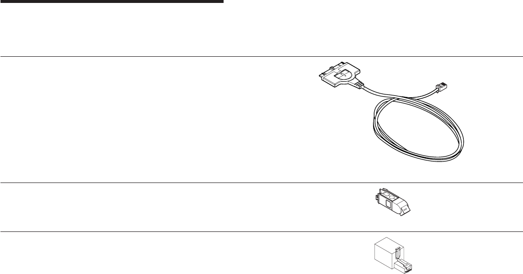
Appendix F. Parts Information
Table 9. Part Numbers
Part Number Description Diagram
38H7044 PC Card Cable
73G8314 STP Connector (RJ-45 for Data
Connector); converts RJ-45 to
Token-Ring
73G2305 RJ-11 to RJ-45 Modular Adapter
To order these items, call the IBM Maintenance Parts and Warranty Center
1-800-388-7080 (United States only).
© Copyright IBM Corp. 1997, 1999 93
94 Turbo 16/4 Token-Ring PC Card 2

Appendix G. Notices and Warranty
References in this publication to IBM products, programs, or services do not imply
that IBM intends to make these available in all countries in which IBM operates. Any
reference to an IBM product, program, or service is not intended to state or imply
that only IBM’s product, program, or service may be used. Any functionally
equivalent product, program, or service that does not infringe any of IBM’s
intellectual property rights may be used instead of the IBM product, program, or
service. Evaluation and verification of operation in conjunction with other products,
programs, or services, except those expressly designated by IBM, are the user’s
responsibility.
IBM may have patents or pending patent applications covering subject matter in this
document. The furnishing of this document does not give you any license to these
patents. You can send license inquiries, in writing, to the IBM Director of Licensing,
IBM Corporation, 500 Columbus Avenue, THORNWOOD NY 10594 USA.
Notice to Users in the United Kingdom
The United Kingdom Telecommunications Act 1984. This apparatus is approved
under General Approval number NS/G/1234/J/100003 for indirect connections to
public telecommunications systems in the United Kingdom.
Electronic Emission Notices
Federal Communications Commission (FCC) Statement
Note:This equipment has been tested and found to comply with the limits for a
Class B digital device, pursuant to Part 15 of the FCC Rules. These limits are
designed to provide reasonable protection against harmful interference in a
residential installation. This equipment generates, uses, and can radiate radio
frequency energy and, if not installed and used in accordance with the instructions,
may cause harmful interference to radio communications. However, there is no
guarantee that interference will not occur in a particular installation. If this
equipment does cause harmful interference to radio or television reception, which
can be determined by turning the equipment on and off, the suer is encouraged to
try to correct the interference by one or more of the following measures:
vReorient or relocate the receiving antenna
vIncrease the separation between the equipment and receiver
vConnect the equipment into an outlet on a circuit different from that to which the
receiver is connected
vConsult an IBM authorized dealer or service representative for help
Properly shielded and grounded cables and connectors must be used in order to
meet FCC emission limits. Proper cables and connectors are available from IBM
authorized dealers. IBM is not responsible for any radio or television interference
caused by using other than recommended cables and connectors or by
unauthorized changes or modifications to this equipment. Unauthorized changes or
modifications could void the user’s authority to operate the equipment.
© Copyright IBM Corp. 1997, 1999 95
This device complies with Part 15 of the FCC Rules. Operation is subject to the
following two conditions:(1) this device may not cause harmful interference, and (2)
this device must accept any interference received, including interference that may
cause undesired operation.
Industry Canada Class B Emission Compliance Statement
This Class B digital apparatus meets the requirements of the Canadian
Interference-Causing Equipment Regulations.
Avid de conformité aux normes d’Industrie Canada
Cet appareil numérique de la classe B respecte toutes les exigences du Règlement
sur le matériel brouilleur du Canada.
European Community (EC) Mark of Conformity Statement
This product is in conformity with the protection requirements of EU Council
Directive 89/336/EEC on the approximation of the laws of the Member States
relating to electromagnetic compatibility. IBM cannot accept responsibility for any
failure to satisfy the protection requirements resulting from a non-recommended
modification of the product, including the fitting of non-IBM option cards.
This product has been tested and found to comply with the limits for Class B
Information Technology Equipment according to CISPR 22 / European Standard EN
55022. The limits for Class B equipment were derived for typical residential
environments to provide reasonable protection against interference with licensed
communication devices.
Dieses Gerät ist berechtigt in Übereinstimmung mit dem deutschen EMVG vom
9.Nov.92 das EG-Konformitätszeichen zu führen. Der Außteller der
Konformitätserklärung ist die IBM Corporation, 3039 Cornwallis Road, Research
Triangle Park, NC 27709.
Dieses Gerät erfüllt die Bedingungen der EN 55022 Klasse B.
Japanese Voluntary Control Council for Interference (VCCI) Statement
This equipment is in the 2nd Class category (information equipment to be used in a
residential area or an adjacent area thereto) and conforms to the standards set by
the Voluntary Control Council for Interference by Information Technology Equipment
aimed at preventing radio interference in such residential areas.
When used near a radio or TV receiver, it may become the cause of radio
interference.
Read the instructions for correct handling.
96 Turbo 16/4 Token-Ring PC Card 2

Trademarks
The following terms are trademarks of the IBM Corporation in the United States or
other countries or both:
AIX Personal System/2
IBM SystemView
Micro Channel ThinkPad
NetView XT
OS/2
Windows and Windows NT are trademarks or registered trademarks of Microsoft
Corporation.
Other company, product, and service names may be trademarks or service marks
of others.
Product Warranty
International Business Machines Corporation Armonk, New York, 10504
Statement of Limited Warranty
The warranties provided by IBM in this Statement of Limited Warranty apply only to Machines you originally purchase
for your use, and not for resale, from IBM or an IBM authorized reseller. The term “Machine” means an IBM machine,
its features, conversions, upgrades, elements, or accessories, or any combination of them. Machines are subject to
these terms only if purchased in the United States or Puerto Rico, or Canada, and located in the country of purchase.
If you have any questions, contact IBM or your reseller.
Machine: IBM Turbo 16/4 Token-Ring PC Card 2
Warranty Period*: Lifetime
*Elements and accessories are warranted for three months. Contact your place of purchase for warranty service
information.
Production Status
Each Machine is manufactured from new parts, or new and serviceable used parts (which perform like new parts). In
some cases, the Machine may not be new and may have been previously installed. Regardless of the Machine’s
production status, IBM’s warranty terms apply.
Appendix G. Notices and Warranty 97
The IBM Warranty
IBM warrants that each Machine 1) is free from defects in materials and workmanship and 2) conforms to IBM’s
Official Published Specifications. IBM calculates the expiration of the warranty period from the Machine’s Date of
Installation. The date on your receipt is the Date of Installation, unless IBM or your reseller informs you otherwise.
During the warranty period, IBM or your reseller will provide warranty service under the type of service designated for
the Machine and will manage and install engineering changes that apply to the Machine. IBM or your reseller will
specify the type of service.
For a feature, conversion, or upgrade, IBM or your reseller may require that the Machine on which it is installed be 1)
the designated, serial-numbered Machine and 2) at an engineering-change level compatible with the feature,
conversion, or upgrade. Some of these transactions (called “Net-Priced” transactions) may include additional parts and
associated replacement parts that are provided on an exchange basis. All removed parts become the property of IBM
and must be returned to IBM.
Replacement parts assume the remaining warranty of the parts they replace.
If a Machine does not function as warranted during the warranty period, IBM in its sole discretion will repair, replace it
(with a Machine that is at least functionally equivalent), or refund the purchase price. To obtain coverage under the
warranty you may be required to present proof of purchase.
This warranty is non-transferable by the end-user customer.
Warranty Service
To obtain warranty service for the Machine, you should contact your reseller or call IBM. In the United States, call IBM
at 1-800-IBM-SERV (426-7378). In Canada, call IBM at 1-800-565-3344. You may be required to present proof of
purchase.
Depending on the Machine, the service may be 1) a “Repair” service at your location (called “On-site”) or at one of
IBM’s or a reseller’s service locations (called “Carry-in”) or 2) an “Exchange” service, either On-site or Carry-in.
When a type of service involves the exchange of a Machine or part, the item IBM or your reseller replaces becomes
its property and the replacement becomes yours. The replacement may not be new, but will be in good working order
and at least functionally equivalent to the item replaced.
It is your responsibility to:
1. obtain authorization from the owner (for example, your lessor) to have IBM or your reseller service a Machine that
you do not own;
2. where applicable, before service is provided —
a. follow the problem determination, problem analysis, and service request procedures that IBM or your reseller
provide,
b. secure all programs, data, and funds contained in a Machine,
c. inform IBM or your reseller of changes in a Machine’s location, and
d. for a Machine with exchange service, remove all features, parts, options, alterations, and attachments not
under warranty service. Also, the Machine must be free of any legal obligations or restrictions that prevent its
exchange; and
3. be responsible for loss of, or damage to, a Machine in transit when you are responsible for the transportation
charges.
Extent of Warranty
IBM does not warrant uninterrupted or error-free operation of a Machine.
Misuse, accident, modification, unsuitable physical or operating environment, improper maintenance by you, or failure
caused by a product for which IBM is not responsible may void the warranties.
THESE WARRANTIES REPLACE ALL OTHER WARRANTIES, EXPRESS OR IMPLIED, INCLUDING, BUT NOT
LIMITED TO, THE IMPLIED WARRANTIES OF MERCHANTABILITY AND FITNESS FOR A PARTICULAR PURPOSE.
HOWEVER, SOME LAWS DO NOT ALLOW THE EXCLUSION OF IMPLIED WARRANTIES. IF THESE LAWS APPLY,
THEN ALL EXPRESS AND IMPLIED WARRANTIES ARE LIMITED IN DURATION TO THE WARRANTY PERIOD. NO
WARRANTIES APPLY AFTER THAT PERIOD.
In Canada, warranties include both warranties and conditions.
98 Turbo 16/4 Token-Ring PC Card 2
Some jurisdictions do not allow limitations on how long an implied warranty lasts, so the above limitation may not
apply to you.
Limitation of Liability
Circumstances may arise where, because of a default on IBM’s part (including fundamental breach) or other liability
(including negligence and misrepresentation), you are entitled to recover damages from IBM. In each such instance,
regardless of the basis on which you are entitled to claim damages, IBM is liable only for:
1. bodily injury (including death), and damage to real property and tangible personal property; and
2. the amount of any other actual loss or damage, up to the greater of $100,000 or the charge for the Machine that is
the subject of the claim.
Under no circumstances is IBM liable for any of the following:
1. third-party claims against you for losses or damages (other than those under the first item listed above);
2. loss of, or damage to, your records or data; or
3. economic consequential damages (including lost profits or savings) or incidental damages, even if IBM is informed
of their possibility.
Some jurisdictions do not allow the exclusion or limitation of incidental or consequential damages, so the above
limitation or exclusion may not apply to you.
This warranty gives you specific legal rights and you may also have other rights which vary from jurisdiction to
jurisdiction.
Appendix G. Notices and Warranty 99
100 Turbo 16/4 Token-Ring PC Card 2

Glossary of Terms and Abbreviations
This glossary defines terms and abbreviations
used in this manual. If you do not find the term
you are looking for, refer to the index or to the
IBM Dictionary of Computing
, SC20-1699 (New
York/ McGraw-Hill, Inc., 1994).
A
access unit. A unit that allows multiple attaching
devices access to a Token-Ring network at a central
point such as a wiring closet or in an open work area.
adapter address. Twelve hexadecimal digits that
identify a LAN adapter.
address. In data communication, the IEEE-assigned
unique code or the unique locally administered code
assigned to each device or workstation connected to a
network. A character, group of characters, or a value
that identifies a register, a particular part of storage, a
data source, or a data sink. The value is represented by
one or more characters. To refer to a device or an item
of data by its address. The location in the storage of a
computer where data is stored. In word processing, the
location, identified by the address code, of a specific
section of the recording medium or storage.
alert. For IBM LAN management products, a
notification indicating a possible security violation, a
persistent error condition, or an interruption or potential
interruption in the flow of data around the network. See
also
network management vector transport
.InSNA,a
record sent to a system problem management focal
point to communicate the existence of an alert
condition. In the NetView program, a high-priority event
that warrants immediate attention. This data base
record is generated for certain event types that are
defined by user-constructed filters.
attach. To make a device a part of a network logically.
Note:
Not to be confused with
connect,
which implies
physically connecting a device to a network.
attaching device. Any device that is physically
connected to a network and can communicate over the
network.
B
Basic Input/Output System (BIOS). In IBM personal
computers with PC I/O channel architecture, microcode
that controls basic hardware operations such as
interactions with diskette drives, fixed disk drives, and
the keyboard.
C
command. A request for performance of an operation
or execution of a program. A character string from a
source external to a system that represents a request
for system action.
configuration. The arrangement of a computer system
or network as defined by the nature, number, and chief
characteristics of its functional units. More specifically,
the term may refer to a hardware configuration or a
software configuration. The devices and programs that
make up a system, subsystem, or network. See also
system configuration
.
configuration parameters. Variables in a
configuration definition, the values of which characterize
the relationship of a product, such as a bridge, to other
products in the same network.
connect. In a LAN, to physically join a cable from a
station to an access unit or network connection point.
Contrast with
attach
.
D
default. Pertaining to an attribute, value, or option that
is assumed when none is explicitly specified.
device driver. The code needed to attach and use a
device on a computer or a network.
diagnostics. Modules or tests used by computer users
and service personnel to diagnose hardware problems.
diskette drive. The mechanism used to seek, read,
and write data on diskettes.
F
fastpath transmit. An alternate transmit interface to
the PC Card that provides higher throughput.
fault. An accidental condition that causes a functional
unit to fail to perform its required function.
fixed disk drive. Synonym for hard disk drive.
frame. The unit of transmission in some LANs,
including the IBM Token-Ring Network and the IBM PC
Network. It includes delimiters, control characters,
information, and checking characters. On a Token-Ring
network, a frame is created from a token when the
token has data appended to it. On a token bus network
(IBM PC Network), all frames including the token frame
contain a preamble, start delimiter, control address,
optional data and checking characters, end delimiter,
and are followed by a minimum silence period. A
© Copyright IBM Corp. 1997, 1999 101
housing for machine elements. In synchronous data link
control (SDLC), the vehicle for every command, every
response, and all information that is transmitted using
SDLC procedures. Each frame begins and ends with a
flag.
H
hard disk drive. A stand-alone disk drive that reads
and writes data on rigid disks and can be attached to a
port on the system unit. Synonymous with fixed disk
drive, hard drive.
hot plugging. The ability to remove your adapter as
long as you have shut down all the applications using
the adapter. When you insert your adapter again, you
can restart those applications.
I
initialize. In a LAN, to prepare the adapter (and
adapter support code, if used) for use by an application
program.
input/output (I/O). Pertaining to a device whose parts
can perform an input process and an output process at
the same time. Pertaining to a functional unit or channel
involved in an input process, output process, or both,
concurrently or not, and to the data involved in such a
process.
insert. To make an attaching device an active part of a
LAN.
interface. A shared boundary between two functional
units, defined by functional characteristics, common
physical interconnection characteristics, signal
characteristics, and other characteristics as appropriate.
A shared boundary. An interface may be a hardware
component to link two devices or a portion of storage or
registers accessed by two or more computer programs.
Hardware, software, or both, that links systems,
programs, or devices.
interrupt. A suspension of a process, such as
execution of a computer program, caused by an
external event and performed in such a way that the
process can be resumed. To stop a process in such a
way that it can be resumed. In data communication, to
take an action at a receiving station that causes the
sending station to end a transmission. A means of
passing processing control from one software or
microcode module or routine to another, or of requesting
a particular software, microcode, or hardware function.
interrupt level. The means of identifying the source of
an interrupt, the function requested by an interrupt, or
the code or feature that provides a function or service.
L
LAN adapter. The circuit card within a communicating
device (such as a personal computer) that, together with
its associated software, enables the device to be
attached to a LAN.
LANAID. The LAN Adapter Installation and Diagnostic
program. This program works to simplify the installation
and configuration of hardware and software in a
non-Plug and Play environment.
LAN Client. IBM LAN Client is a protocol stack that
operates in protected mode in the DOS TCP/IP, Novell
IPX Client, NetBIOS, and IEEE 802.2 environments.
locally administered address. An adapter address
that the user can assign to override the universally
administered address. Contrast with
universally
administered address
.
M
MAC frame. Frames used to carry information to
maintain the ring protocol and for exchange of
management information.
medium access control (MAC) protocol. In a local
area network, the part of the protocol that governs
communication on the transmission medium without
concern for the physical characteristics of the medium,
but taking into account the topological aspects of the
network, in order to enable the exchange of data
between data stations.
message. A logical partition of the user device’s data
stream to and from the adapter. A group of characters
and control bits transferred as an entity.
Micro Channel. The architecture used by IBM
Personal System/2 computers, Models 50 and above.
This term is used to distinguish these computers from
personal computers using a PC I/O channel, such as an
IBM PC, XT, or an IBM Personal System/2 computer,
Model 25 or 30.
N
network administrator. A person who manages the
use and maintenance of a network.
node. Any device, attached to a network, that
transmits and/or receives data. An endpoint of a link, or
a junction common to two or more links in a network. In
a network, a point where one or more functional units
interconnect transmission lines.
node address. The address of an adapter on a LAN.
102 Turbo 16/4 Token-Ring PC Card 2
O
open. To make an adapter ready for use. A break in
an electrical circuit. To make a file ready for use.
operating system. Software that controls the
execution of programs. An operating system may
provide services such as resource allocation,
scheduling, input/output control, and data management.
Examples are IBM PC DOS and IBM OS/2.
option. A specification in a statement, a selection from
a menu, or a setting of a switch, that may be used to
influence the execution of a program. A hardware or
software function that may be selected or enabled as
part of a configuration process. A piece of hardware
(such as a network adapter) that can be installed in a
device to modify or enhance device function.
P
panel. The complete set of formatted information that
appears in a single display on a visual display unit.
parameter. A variable that is given a constant value
for a specified application and that may denote the
application. An item in a menu or for which the user
specifies a value or for which the system provides a
value when the menu is interpreted. Data passed
between programs or procedures.
PC Card. In a LAN, within a communicating device, a
circuit card that, with its associated software and/or
microcode, enables the device to communicate over the
network.
port. An access point for data entry or exit. A
connector on a device to which cables for other devices
such as display stations and printers are attached.
Synonymous with
socket
.
protocol. A set of semantic and syntactic rules that
determines the behavior of functional units in achieving
communication. In SNA, the meanings of and the
sequencing rules for requests and responses used for
managing the network, transferring data, and
synchronizing the states of network components. A
specification for the format and relative timing of
information exchanged between communicating parties.
R
random access memory (RAM). A computer’s or
adapter’s volatile storage area into which data may be
entered and retrieved in a nonsequential manner.
read-only memory (ROM). A computer’s or adapter’s
storage area whose contents cannot be modified by the
user except under special circumstances.
remove. To take an attaching device off a network. To
stop an adapter from participating in data passing on a
network.
ring network. A network configuration in which a
series of attaching devices is connected by
unidirectional transmission links to form a closed path. A
ring of an IBM Token-Ring Network is referred to as a
LAN segment or as a Token-Ring Network segment.
S
server. A device, program, or code module on a
network dedicated to providing a specific service to a
network. On a LAN, a data station that provides facilities
to other data stations. Examples are a file server, print
server, and mail server.
shallowmode. A new mode that allows the workstation
to assist the PC Card in the reception of information
from the Token Ring. When chosen, fastpath transmit is
used as well.
shared RAM. Random access memory (RAM) on an
adapter that is shared by the computer in which the
adapter is installed.
socket. Synonym for
port (2)
.
system. In data processing, a collection of people,
machines, and methods organized to accomplish a set
of specific functions.
system configuration. A process that specifies the
devices and programs that form a particular data
processing system.
T
telephone twisted pair. One or more twisted pairs of
copper wire in the unshielded voice-grade cable
commonly used to connect a telephone to its wall jack.
Also referred to as “unshielded twisted pair” (UTP).
token. A sequence of bits passed from one device to
another on the Token-Ring network that signifies
permission to transmit over the network. It consists of a
starting delimiter, an access control field, and an end
delimiter. The access control field contains a bit that
indicates to a receiving device that the token is ready to
accept information. If a device has data to send along
the network, it appends the data to the token. When
data is appended, the token then becomes a frame.
See
frame
.
Token Ring. A network with a ring topology that
passes tokens from one attaching device (node) to
another. A node that is ready to send can capture a
token and insert data for transmission.
Token-Ring network. A ring network that allows
unidirectional data transmission between data stations
Glossary of Terms and Abbreviations 103
by a token-passing procedure over one transmission
medium so that the transmitted data returns to and is
removed by the transmitting station. The IBM
Token-Ring Network is a baseband LAN with a
star-wired ring topology that passes tokens from
network adapter to network adapter. A network that
uses a ring topology, in which tokens are passed in a
sequence from node to node. A node that is ready to
send can capture the token and insert data for
transmission. A group of interconnected Token Rings.
twisted pair. A transmission medium that consists of
two insulated conductors twisted together to reduce
noise.
U
universally administered address. The address
permanently encoded in an adapter at the time of
manufacture. All universally administered addresses are
unique. Contrast with
locally administered address
.
unshielded twisted pair (UTP). See
telephone twisted
pair
.
104 Turbo 16/4 Token-Ring PC Card 2

Index
A
AutoSense 20
autoset mode 39, 40
C
card services
advantages 39
and hot plugging 5
description 38
disadvantages 39
if using 4
problems during reboot 49
versus point enablers 39
card services enabler 39
CD-ROM content 45
checklist 3
configuring the PC Card 33
D
device driver, NDIS 2 26, 27
diagnostics error codes 81
diagnostics program 81
DOS 76
Error Codes 76
DOS Client-16 28
DOS Error Codes 76
E
EMM386.EXE 49
error codes
diagnostics 81, 83, 86
DOS 76
listing 50
NDIS 62, 76
OS/2 62
expanded memory specification 42
H
hardware problem 50
hot-pluggability 7
hot plugging 5
I
IBM PC hotline 50
IBM Turbo 16/4 Token-Ring PC Card 2 1
IBMTOKCS.DOS 49
IEEE 802.2 1
initialization error codes 81
installation
DOS environments 9
inserting PC Card 5
removing PC Card 6
installation
(continued)
tips 9
installing the software 33
Intel 37
interface software
DOS 37
OS/2 37
K
kit contents 3
L
LANAID 33
LANAID, installing with 33
lanaidc parameters 87
M
memory conflicts 39
memory manager 40, 49
expanded memory specification 42
with card and socket services 41
with point enablers 40
memory managers with card and socket services 41
memory managers with point enablers 40
Microsoft Windows for Workgroups/NDIS 2 27
MPTS 26
Multiple Protocol Transport Services (MPTS) 26
N
NDIS device driver 26
NDIS device driver 26
parameters 20
with MPTS 26
with other programs 27
NDIS Error Codes 62, 76
NDIS MAC parameters 20
notices 95
trademarks 97
Novell NetWare Client32 for Windows 95 19
O
ODI 16–bit parameters 29
open error codes 83
OS/2 26
Error Codes 62
OS/2 NDIS 2 device driver 26
OS/2 NDIS device driver 27
P
parameters, autoringspeed 31
parameters, BUS ID PCMCIA 3 31
parameters, datarate 20
© Copyright IBM Corp. 1997, 1999 105
parameters, driver 20
parameters, enhancedmode 31
parameters, expressmode 31
parameters, frame 20, 30
parameters, fullduplex 21
parameters, LAN Client driver 20
parameters, max frame size 30
parameters, mem1 21
parameters, NIC UAA 30
parameters, node 21
parameters, node address 29
parameters, nofulltuplex 30
parameters, noshallowmode 30
parameters, Novell NetWare Server 20
parameters, PCMCIA 31
parameters, port 29
parameters, receivebuffersize 31
parameters, slot 21
part numbers 93
PC Card 1
connector 6
inserting 5
latching button 6
removal 6
PCMCIA 1, 4
PCMCIA bus support 10
Phoenix Card Services 41, 42
point connectivity enablers 37
advantages 38
disadvantages 38
versus Card and Socket Services 39
point enabler 49
problem determination 49
R
RJ-45 connector 5
RT= 22
RTHT= 22
RTSW= 22
RTTS= 22
running the diagnostics program 81
S
service numbers 50
shielded twisted-pair cabling 5
socket services
and hot plugging 5
description 38
if using 4
versus point enablers 39
software 37
configuration 37
interface 37
software configuration 37
software packages 45
statement of limited warranty 97
STP 5
support 50
T
TCP/IP Version 1.2 for OS/2 27
TCP/IP Version 2.0 for OS/2 27
test options, diagnostic 81
token.lan driver 10
TPRn= 23
trademarks 97
transmit buffer 1
transmit error codes 86
troubleshooting 50
U
unshielded twisted-pair cabling 5
UPRn= 23
UTP 5
W
warranty 95, 97
Windows 2000 23
Windows 95 23
Windows 98 23
Windows NT 23
106 Turbo 16/4 Token-Ring PC Card 2