C H Systems RF-CHWDSC Door/Window Sensors for Security System User Manual
Cinch Systems, Inc Door/Window Sensors for Security System
Contents
- 1. User Manual
- 2. User Manual II
User Manual

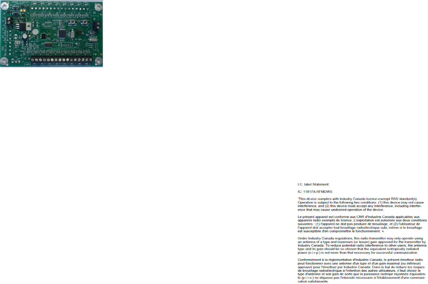
Hardwire to Wireless Converter
RF-CHW-ITI-8 - 433 MHz
Descripon:
The RF-CHW-ITI-8 module allows the conversion of
hardwire security sensors to Qolsys wireless tech-
nology. The module is a cost eecve way of up-
grading a security system and using exisng hard-
wire security zones. The module supports both
magnec contacts and powered zones (12VDC) as
moon detectors (power required from second
source). The module uses the exisng EOL resistors
so no re-wiring or changing out EOL’s is required.
Installaon:
Mounng locaon - if retrong an exisng hard-
wire control panel, mount the module at that loca-
on to minimize splicing wires.
Note: if possible use the exisng enclosure to house
the module and baery, remember the antenna on
the module must protrude from any metal enclo-
sure.
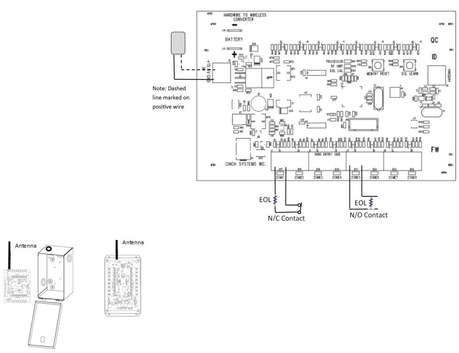
Wiring (see wiring diagram)
Power transformer - 2 conductor
Zone wiring - from exisng control panel
Backup baery
Note: use 22 AGW minimum
Note: Make sure EOL resistors remain in place for
all zones
RF-CHW-ITI-8 - 433MHz
Programming:
The RF-CHW-ITI-8 module is a wireless device that
enrolls into the Qolsys control panel. The module has
a unique ID # that the control panel responds to for
tamper and low baery condions. Also each zone is
assigned it’s own ID# for reporng purposes.
Module setup:
Clear Memory:
Disconnect all power baery and transformer,
press and hold the memory reset buon while
applying power
The LED’s will ash indicang memory reset
Power module by plugging in the transformer
and connecng backup baery if required
Notes:
Polarity on transformer marked as dashed line
on posive wire
Make sure all input EOL’s are properly wired for
N/O (parallel) or N/C (series) conguraon
All zones must be wired with an EOL resistor,
either a 3K ohm from the accessory kit or the
exisng resistor from the previous system
Place all zones in normal non alarm condion
Enrolling zones into the Qolsys panel:
Enroll EOL’s and zones
Put the module in Learn Zone mode by pressing
the EOL Learn buon and holding for 5 seconds,
all LEDs will ash, this process also learns in all of
the EOL’s
Enter system programming on the Qolsys panel
Sengs menu, enter user code
Installaon menu, Security Sensors,
Auto Learn
Sensor
Enroll zones by acvang the zone, the Qolsys
panel will respond with each successful wireless
acvaon and required zone type and name
selecon before the next zone is tripped.
Aer all zones are enrolled press the EOL Learn
Buon to exit program mode on the module, all
LED’s will go out
Note: Learning zones cannot be done if the EOL Cali-
braon LED is Flashing or O
Tesng
On the Qolsys panel enter Sengs, enter user
code
Press System Test, Sensor Test
Acvate all zones on the module and verify they
Pass
FCC label statement:
“This device complies with part 15 of the FCC Rules. Operaon is subject to
the following two condions: (1) This device may not cause harmful interfer-
ence, and (2) this device must accept any interference received, including
interference that may cause undesired operaon.”
“Note: This equipment has been tested and found to comply with the limits
for a Class B digital device, pursuant to part 15 of the FCC Rules. These limits
are designed to provide reasonable protecon against harmful interference
in a residenal installaon. This equipment generates, uses and can radiate
radio frequency energy and, if not installed and used in accordance with the
instrucons, may cause harmful interference to radio communicaons.
However, there is no guarantee that interference will not occur in a parcu-
lar installaon. If this equipment does cause harmful interference to radio or
television recepon, which can be determined by turning the equipment o
and on, the user is encouraged to try to correct the interference by one or
more of the following measures:
—Reorient or relocate the receiving antenna.
—Increase the separaon between the equipment and receiver.
—Connect the equipment into an outlet on a circuit dierent from that to
which the receiver is connected.
—Consult the dealer or an experienced radio/TV technician for help.”
“Changes or modicaons not expressly approved by the party responsible
for compliance could void the user's authority to operate the equipment”
“RF Exposure Guidance: This equipment complies with FCC radiaon expo-
sure limits set forth for an uncontrolled environment. This equipment should
be installed and operated with a minimum distance of 1.5cm between the
radiator and persons. This transmier must not be co-located or operang in
conjuncon with any other antenna or transmier, except in accordance
with FCC mul-transmier product procedures.”

Specicaons:
Input Voltage: 16.0VDC plug-in transformer
Backup Baery: 12VDC 5Ah max (oponal)
Dimensions: 5.5” X 3.5”
Operang Temperature: 32 to 122F (0 to 50C)
Humidity: 95% RH Max
EOL Supervision: 1K to 10K Ohm
Input Zones: 8 (if used must have EOL resistor)
Zone Type—N/O or N/C compable
Auxiliary Voltage Output: 12VDC @ 500mA
Cinch Sck Port: Field upgradable rmware
Relay Contact—60VDC/1A Max, used to drive
siren or other device
Notes:
Used zones must have an EOL installed
Make sure when installed the antenna is
free of all metal obstrucons
Module Switches:
EOL Learn - used to calibrate EOL resistors and enter
program mode
Memory Reset - clears memory of module
Module LED’s
Processor - ashes during normal operaon
RF Xmit - ashes when an RF transmission is sent
EOL Cal: On - calibraon required, O - calibraon
complete
Zones: Flash twice when ready to enroll, On - when
enrolled in programming and when tripped, O -
when zone in normal condion
Metal Enclosure
Plasc Enclosure