C H Systems RF-RDWS-AAA Recessed Door/Window Sensor used by Security Systems User Manual
Cinch Systems, Inc Recessed Door/Window Sensor used by Security Systems
User Manual

Wireless Recessed Sensor—Installaon Instrucons
Recessed Wireless Sensor and Accessories
1 - RF-RDWS-AAA 1 - RF-RDWS Magnet 1 - Baery ( CR2 3V) Instrucons
Doc # I-RF-RDWS-AAA Rev. A Sep 2015
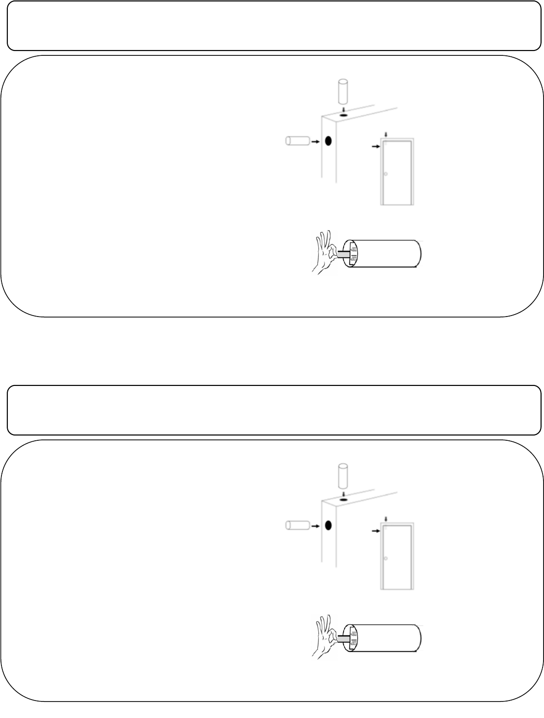
Mounng the Transmier:
1. Verify mounng locaon before drilling any holes,
the area must be able to accept an 11/16” hole to a
depth of 2 1/4” for the sensor and 5/8” for the mag-
net
2. The holes must be drilled directly across from each
other to ensure the magnet and sensor operate
properly
3. Using an 11/16” drill bit drill the hole for the magnet
rst, aer drilling the magnet hole mark the locaon
directly across for the sensor hole.
4. The magnet and sensor are slightly larger than the
drilled hole to ensure a snug t, a small amount of
roung the hole may be required
5. Push both magnet and sensor into mounng holes.
Programming:
1. Remove the cap from the sensor by using a screw-
driver and twisng the cap
2. Pull the baery tab out to power the sensor
Note: The sensor should
be mounted in the door
and the magnet in the
frame.
Carefully pull out baery tab to power the sensor
Mount in
top or side
of door

FCC label statement:
“This device complies with part 15 of the FCC Rules. Operation is subject to the
following two conditions: (1) This device may not cause harmful interference, and
(2) this device must accept any interference received, including interference that
may cause undesired operation.”
“Note: This equipment has been tested and found to comply with the limits for a
Class B digital device, pursuant to part 15 of the FCC Rules. These limits are
designed to provide reasonable protection against harmful interference in a
residential installation. This equipment generates, uses and can radiate radio
frequency energy and, if not installed and used in accordance with the instructions,
may cause harmful interference to radio communications. However, there is no
guarantee that interference will not occur in a particular installation. If this equip-
ment does cause harmful interference to radio or television reception, which can be
determined by turning the equipment off and on, the user is encouraged to try to
correct the interference by one or more of the following measures:
—Reorient or relocate the receiving antenna.
—Increase the separation between the equipment and receiver.
—Connect the equipment into an outlet on a circuit different from that to which the
receiver is connected.
—Consult the dealer or an experienced radio/TV technician for help.”
“Changes or modifications not expressly approved by the party responsible for
compliance could void the user's authority to operate the equipment”
“RF Exposure Guidance: This equipment complies with FCC radiation exposure
limits set forth for an uncontrolled environment. This equipment should be installed
and operated with a minimum distance of 1.5cm between the radiator and persons.
This transmitter must not be co-located or operating in conjunction with any other
antenna or transmitter, except in accordance with FCC multi-transmitter product
procedures.”
ISED RSS-Gen Notice:
IC: 11817A-RFRDWSAAA
“(1) This device may not cause interference; and (2) This device must accept any
interference, including interference that may cause undesired operation of the
device.
(1) L’appareil ne doit pas produire de brouillage; 2) l’appareil doit accepter tout
brouillage radioélectrique subi, même si le brouillage est susceptible d’en
compromettre le fonctionnement”
Under Industry Canada regulations, this radio transmitter may only operate using
an antenna of a type and maximum (or lesser) gain approved for the transmitter by
Industry Canada. To reduce potential radio interference to other users, the antenna
type and its gain should be so chosen that the equivalent isotropically radiated
power (e.i.r.p.) is not more than that necessary for successful communication.
Conformément à la réglementation d'Industrie Canada, le présent émetteur radio
peut fonctionner avec une antenne d'un type et d'un gain maximal (ou inférieur)
approuvé pour l'émetteur par Industrie Canada. Dans le but de réduire les risques
de brouillage radioélectrique à l'intention des autres utilisateurs, il faut choisir le
type d'antenne et son gain de sorte que la puissance isotrope rayonnée équivalen-
te (p.i.r.e.) ne dépasse pas l'intensité nécessaire à l'établissement d'une communi-
cation satisfaisante.
Doc # I-RF-RDWS-AAA Rev. A Sep 2015
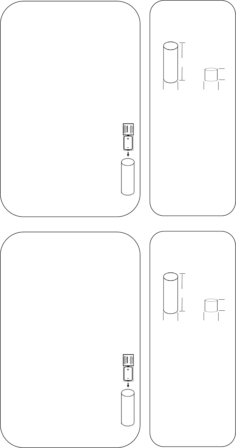
Specicaons:
Dimensions:
Baery: CR2 3V
WARNING: The polarity of the baery
must be observed, as shown. Improper han-
dling of lithium baeries may result in heat
generaon, explosion or re, resulng in
personal injuries. Replace only with the same
or equivalent type of baery as recommended
by the manufacturer (see Specicaons).
Baeries must not be recharged, disassembled
or disposed of in re. Disposal of used baeries
must be made in accordance with the waste
recovery and recycling regulaons in your area.
Keep Away From Small Children. If baeries are
swallowed, promptly seek medical aenon.
3. Aer the baery tab is pulled the sensor will
transmit “tampers” for the rst ves acvaons,
the sensor should be enrolled during one of
these rst ve trips. If the device is tripped too
many mes before enrollment the baery must
be removed and re-installed to acvate the tam-
per trips again.
4. Refer to the panel installaon instrucons for
specic programming informaon
Baery Replacement:
1. Remove the sensor cap and carefully
pull out the circuit board
2. Push out the old baery towards the
antennas and replace with a new
baery
3. Carefully slide board back into housing,
note the slot for alignment
4. Replace the cap and acvate the device
at least ve mes
2 1/4”
3/4”
5/8”
3/4”
Sensor Magnet