C MAX Asia CM9209V402015 2.4GHz Module User Manual 2ABBXCM9209V402015 UseMan
C-MAX Asia limited 2.4GHz Module 2ABBXCM9209V402015 UseMan
User Manual
CMM-9209-V4.0
Long Range 2.4GHz Transceiver Module
This module is limited to OEM installation ONLY
SPEC No.
CMM-9209-V4.0
2.4GHz Transceiver
module
Revision
1.6
State
2015-02-25
C-MAX printed
2015-02-25
Version
English
Page
1 of 10
C-MAX
Description
The CMM-9209 module is a miniaturised long range 2.4GHz transceiver module based on EM Micro-
electronic’s RF transceiver EM9209. The module is highly optimized for long-range wireless application
requiring ultra low power consumption and short time-to-market. It offers a plug and play solution for
any EM9209 application without any additional hardware nor RF layout. Built in with a PCB strip
antenna, this small sized, low cost module provides an ideal solution to wireless 2.4GHz license-free
application worldwide.
The EM9209 is a low-voltage 2.4GHz transceiver IC with built-in link-layer logic permitting proprietary
wireless links in the license-free 2.400 … 2.4835 GHz ISM band. This solution is ideal for battery
operated wireless applications such as wireless sensors and control, toys, human interface devices,
security and metering networks.
1.1 Features
o Fully integrated 2.4 GHz transceiver (Chip on Board)
o Operating voltage 1.9V ~ 3.6V
o Mini-sized (18.5mm x 14mm)
o Programmable RF output level (-10 dBm to +10 dBm) via software control
o Low current consumption
(1uA at power down mode, 8.2 mA RX (high sensitivity mode), 11.2 mA in TX mode (-1 dBm))
o No Tuning necessary
o Programmable data rate (3kbps, 6 kbps, 12 kbps)
o Reaches max 500m in open space line of sight
o FSK modulation
o SPI interface to host controller
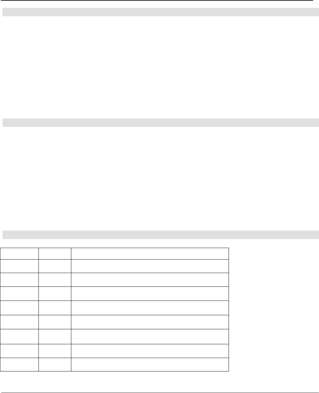
1.2 Module Dimension & Pin Assignments
Pin Number Pin Name Pin Description
1 GND Ground Connection
2 EN_REG Master Chip Enable Signal
3 IRQ Interrupt Output for external host Controller
4 MISO SPI Data Output
5 MOSI SPI Data Input
6 SS
\
SPI Slave Select(Active High)
7 SCK SPI Clock Input
8 VDD Positive Power Supply
CMM-9209-V4.0
Long Range 2.4GHz Transceiver Module
SPEC No.
CMM-9209-V4.0
2.4GHz Transceiver
module
Revision
1.6
State
2015-02-25
C-MAX printed
2015-02-25
Version
English
Page
2 of 10
C-MAX
Top View Bottom View
*** Connection pin pitch : 1.27mm
CMM-9209-V4.0/4.0P Module Thickness (excluding pin header connectors, excluding shielding) = 2.1mm max.
CMM-9209-V4.0F/4.0X Module Thickness (excluding pin header connectors, including shielding) = 3.3mm max.
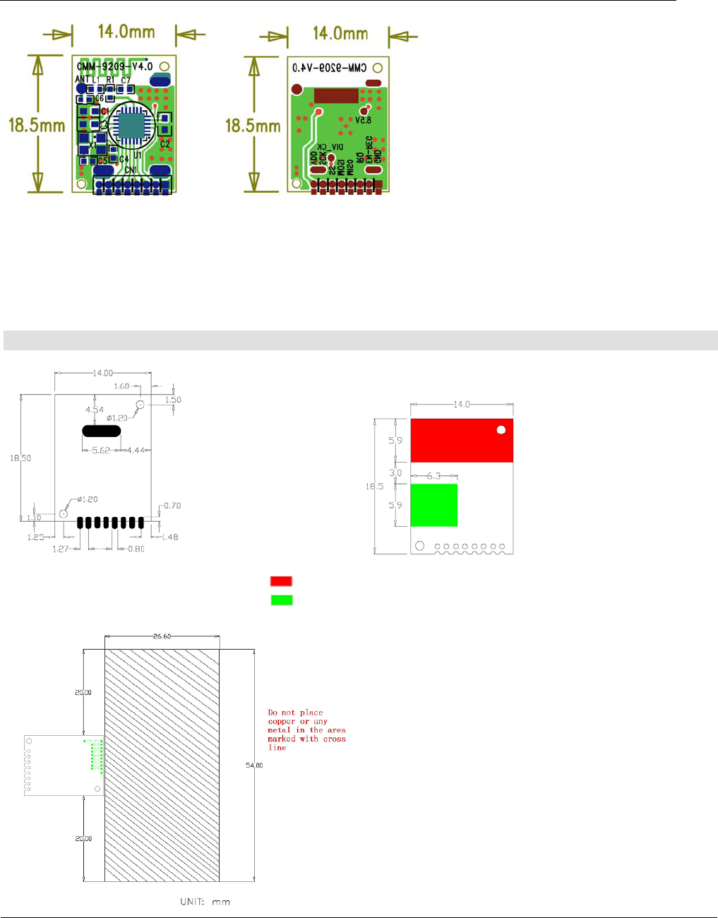
1.3 Recommended PCB layout and foot print
Footprint: Layout Under Module:
Layout Around module: : Clearance area (no routing, components or copper plane)
: Ground plane recommended
CMM-9209-V4.0
Long Range 2.4GHz Transceiver Module
SPEC No.
CMM-9209-V4.0
2.4GHz Transceiver
module
Revision
1.6
State
2015-02-25
C-MAX printed
2015-02-25
Version
English
Page
3 of 10
C-MAX
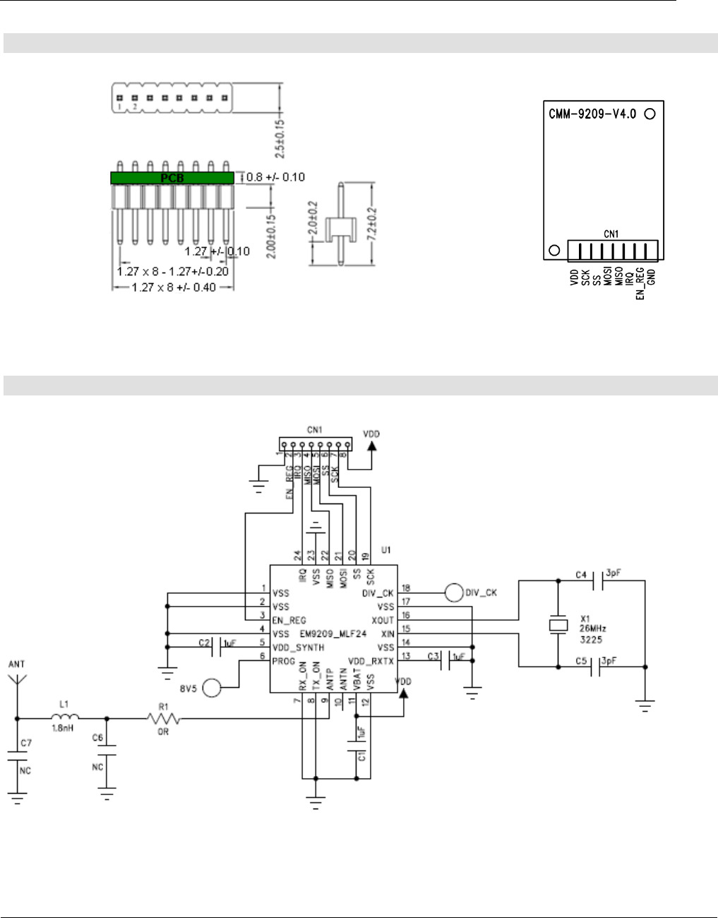
1.4 Pinning Dimensions and definitions
Pin Connection Dimension (applicable only for CMM-9209-V4.0P/4.0X) Pin Definition
1.5 Module Reference Circuit diagram
CMM-9209-V4.0
Long Range 2.4GHz Transceiver Module
SPEC No.
CMM-9209-V4.0
2.4GHz Transceiver
module
Revision
1.6
State
2015-02-25
C-MAX printed
2015-02-25
Version
English
Page
4 of 10
C-MAX
1.6 Module Electrical Specifications
Specification CMM-9209-V4.0/4.0P/4.0F/4.0X
Voltae Range 1.9V to 3.6V
Frequency Range 2.408 to 2.474 GHz
Modulation FSK
On-air data rate configurable 3 kbps, 6 kbps, 12 kbps
Maximum Allowable Data bytes in payload
per transmission Data rate
(Kbps)
Preamble
(byte)
Address
(byte)
header
(byte)
Payload
(byte)
3 2 3 1 8
6 2 3 1 31
12 2 3 1 31
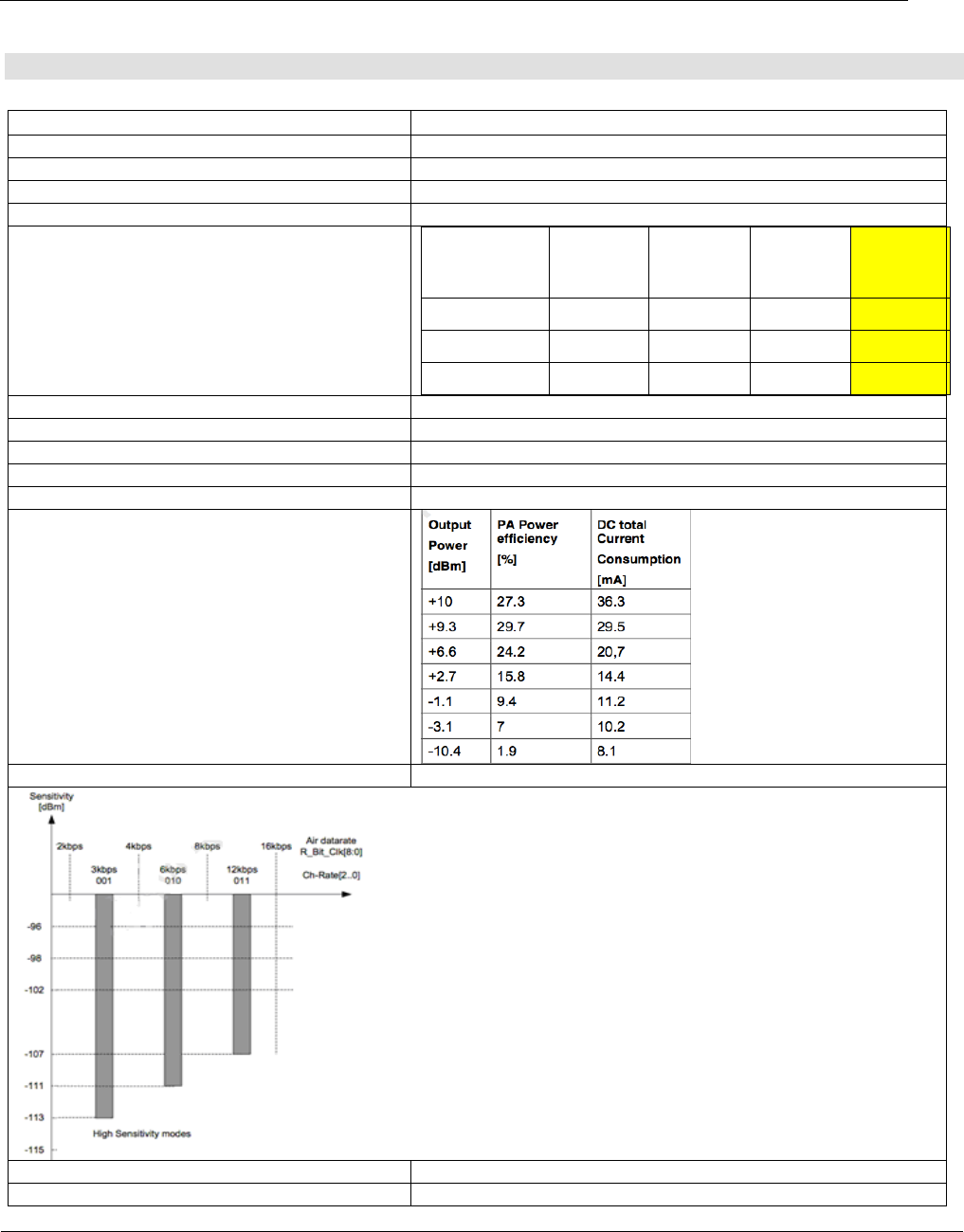
Current Consumption (Vcc = 2.5V)
- RX mode 8.2mA (High sensitivity mode)
- TX mode varies according to output power (see below)
- Standby mode 140 uA (typ.)
- Power-down mode 1uA
Programmable output power vs TX current
consumption
Module Sensitivity
RF setup time (Standby <-> TX/RX) Max 200 us
CMM-9209-V4.0
Long Range 2.4GHz Transceiver Module
SPEC No.
CMM-9209-V4.0
2.4GHz Transceiver
module
Revision
1.6
State
2015-02-25
C-MAX printed
2015-02-25
Version
English
Page
5 of 10
C-MAX
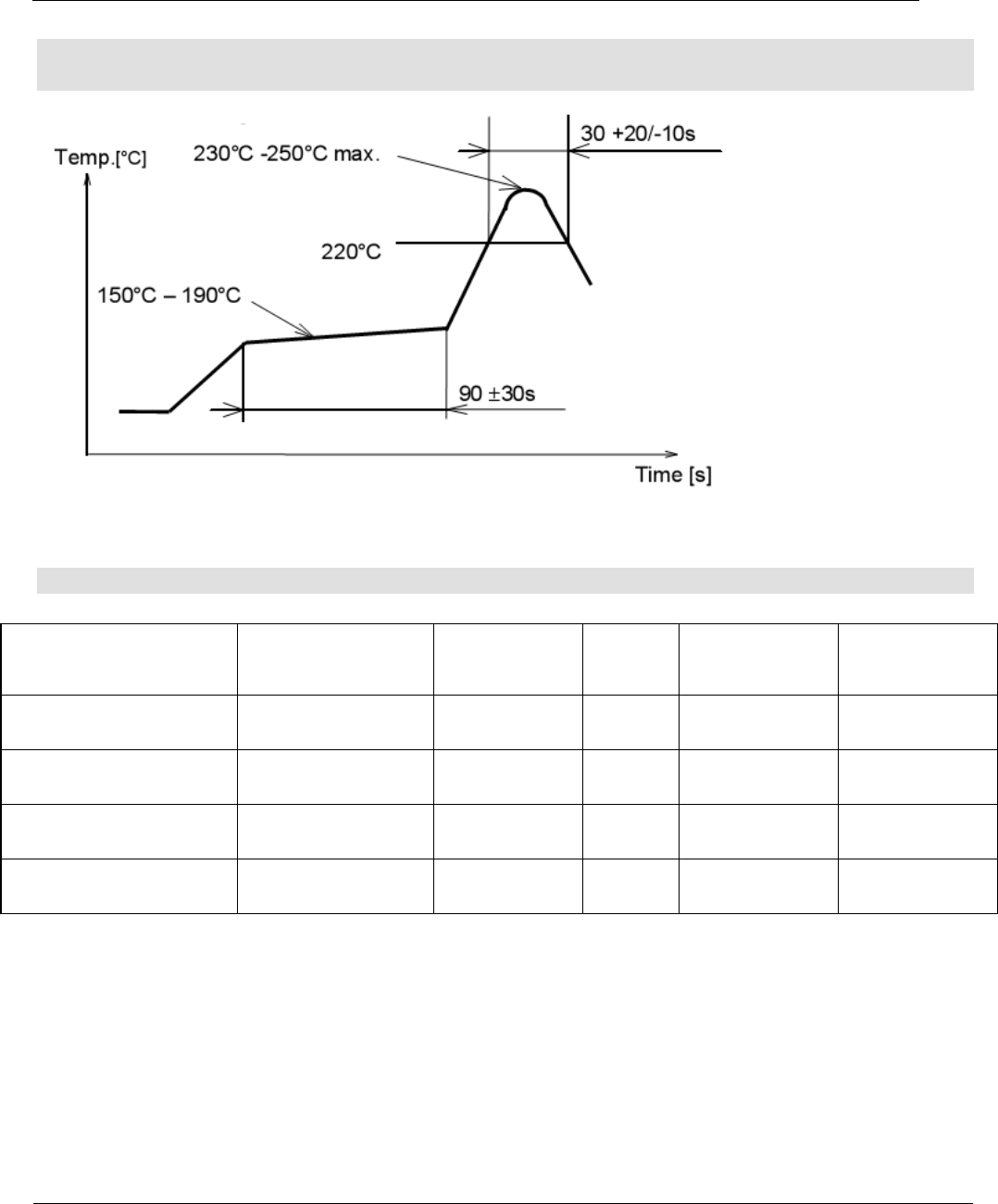
2. Temperature Profile for Lead-free Reflow Soldering
(only applicable for CMM-9209-V4.0F)
3. Ordering information
Module Part Number Module Assembly
process type
Pin Headers
on Module
Shield
on
Module
Qualification
Cert. Packaging
CMM-9209-V4.0 Hand soldering X X
FCC, CE pre-
scan passed In Trays
CMM-9209-V4.0F SMT + reflow X √
FCC, CE
Pending Tape & Reel
CMM-9209-V4.0P Plug-in √X
FCC, CE pre-
scan passed In Trays
CMM-9209-V4.0X Plug-in √√
FCC, CE
Pending In Trays

CMM-9209-V4.0
Long Range 2.4GHz Transceiver Module
SPEC No.
CMM-9209-V4.0
2.4GHz Transceiver
module
Revision
1.6
State
2015-02-25
C-MAX printed
2015-02-25
Version
English
Page
6 of 10
C-MAX
4. Packaging Information
CMM-9209-V4.0F - Tape and Reel
Item D0 D
1 P
0 P
2 E W A
0 A
1
Dimension 1.50
+0.10-0.00
0.00
+0.00-0.00
4.00
+0.10-0.10
2.00
+0.10-0.10
1.75
+0.10-0.10
32.0
+0.30-0.30
14.3
+0.10-0.10
0.00
+0.10-0.10
Item B0 B
1 K
0 K
1 P F T
Dimension 19.1
+0.10-0.10
0.00
+0.00-0.00
3.40
+0.10-0.10
0.00
+0.10-0.10
20.0
+0.10-0.10
14.2
+0.10-0.10
0.30
+0.05-0.05
5. FCC Statement
NOTICE: This device complies with Part 15 of the FCC Rules. Operation is subject to the following two
conditions:
This device may not cause harmful interference, and
This device must accept any interference received, including interference that may cause
undesired operation.
The Grantee is not responsible for any changes or modifications not expressly approved by the party
responsible for compliance. Such modifications could void the user’s authority to operate the
equipment.
This equipment has been tested and found to comply with the limits for a Class B digital device,
pursuant to Part 15 of the FCC Rules. These limits are designed to provide reasonable protection
against harmful interference in a residential installation. This equipment generates, uses and can
radiate radio frequency energy and if not installed and used in accordance with the instructions, may
cause harmful interference to radio communications. However, there is no guarantee that interference
will not occur in a particular installation. If this equipment does cause harmful interference to radio or
television reception, which can be determined by turning the equipment off and on, the user is
encouraged to try to correct the interference by one or more of the following measures:

CMM-9209-V4.0
Long Range 2.4GHz Transceiver Module
SPEC No.
CMM-9209-V4.0
2.4GHz Transceiver
module
Revision
1.6
State
2015-02-25
C-MAX printed
2015-02-25
Version
English
Page
7 of 10
C-MAX
Reorient or relocate the receiving antenna.
Increase the separation between the equipment and receiver
Connect the equipment into an outlet on a circuit different from that to which the receiver is
connected.
Consult the dealer or an experienced radio/TV technician for help
Radio frequency radiation exposure information:
This equipment complies with FCC radiation exposure limits set forth for an uncontrolled environment.
Please see the RF Exposure information. This transmitter must not be co-located or operating in
conjunction with any other antenna or transmitter.
This device should be installed and operated with a minimum distance of 20cm between the antenna
and all persons.
Label requirements:
Contains: FCC ID: 2ABBXCM9209V402015
FCC RF Exposure Requirement:
At least 20cm separation distance between the antenna and the user’s body must be maintained at
all times. And must not transmit simultaneously with any other antenna or transmitter, except in
accordance with FCC multi transmitter product procedures.
To comply with FCC regulations limiting both maximum RF output power and human exposure to
RF radiation, the maximum antenna gain including cable loss in a mobile-only exposure condition
must not exceed 0dBi in the 2.4GHz band.
A user manual with the end product must clearly indicate the operating requirements and conditions
that must be observed to ensure compliance with current FCC RF exposure guidelines.
Note: If this module is intended for use in a portable device, you are responsible for separate approval
to satisfy the SAR requirements of FCC Part 2.1093.
Please be noted that the following information and instructions should be placed in the end-
user’s operating manual.
The CMM-9209-V4.0 Module must be installed in the designated host as specified in this manual.
Separate approval is required for all other operating configurations, including portable
configurations with respect to 2.1093 and different antenna configurations.
The CMM-9209-V4.0 Module and its antenna must not be co-located or operating in conjunction
with any other transmitter or antenna within a host device. This equipment complies with FCC RF
radiation exposure limits set forth for an uncontrolled environment.
A label must be affixed to the outside of the end product into which the CMM-9209-V4.0 Module is
incorporated, with a statement similar to the following: For CMM-9209-V4.0: This device contains
FCC ID: 2ABBXCM9209V402015.
The module shall be in non-detachable construction protection into the finished products, so that
the end-user has to destroy the module while remove or install it.
This module is to be installed only in mobile or fixed applications. According to FCC part 2.1091(b)
definition of mobile and fixed devices is:

CMM-9209-V4.0
Long Range 2.4GHz Transceiver Module
SPEC No.
CMM-9209-V4.0
2.4GHz Transceiver
module
Revision
1.6
State
2015-02-25
C-MAX printed
2015-02-25
Version
English
Page
8 of 10
C-MAX
Mobile Device:
A mobile device is defined as a transmitting device designed to be used in other than fixed
locations and to generally be used in such a way that a separation distance of at least 20
centimeters is normally maintained between the transmitter’s radiating structure(s) and the body of
the user or nearby persons. In this context, the term ‘‘fixed location’’ means that the device is
physically secured at one location and is not able to be easily moved to another location.
Portable Device:
For purposes of this section, a portable device is defined as a transmitting device designed to be
used so that the radiating structure(s) of the device is/are within 20 centimeters of the body of the
user.
Separate approval is required for all other operating configurations, including portable
configurations with respect to FCC Part 2.1093 and different antenna configurations.
A certified modular has the option to use a permanently affixed label, or an electronic label. For a
permanently affixed label, the module must be labeled with an FCC ID: 2ABBXCM9209V402015.
The OEM manual must provide clear instructions explaining to the OEM the labeling requirements,
options and OEM user manual instructions that are required.
For a host using this FCC certified modular with a standard fixed label, if (1) the module’s FCC ID is
not visible when installed in the host, or (2) if the host is marketed so that end users do not have
straightforward commonly used methods for access to remove the module so that the FCC ID of
the module is visible; then an additional permanent label referring to the enclosed module:
“Contains: FCC ID : 2ABBXCM9209V402015” must be used. The host OEM user manual must also
contain clear instructions on how end users can find and/or access the module and the FCC ID.
Host product is required to comply with all applicable FCC equipment authorizations regulations,
requirements and equipment functions not associated with the transmitter module portion,
compliance must be demonstrated to regulations for other transmitter components within the host
product; to requirements for unintentional radiators (Part 15B). To ensure compliance with all non-
transmitter functions the host manufacturer is responsible for ensuring compliance with the
module(s) installed and fully operational. If a host was previously authorized as an unintentional
radiator under the Declaration of Conformity procedure without a transmitter certified module and
a module is added, the host manufacturer is responsible for ensuring that after the module is
installed and operational the host continues to be compliant with the Part 15B unintentional
radiator requirements. Since this may depend on the details of how the module is integrated with
the host, the grantee (the party responsible for the module grant) shall provide guidance to the
host manufacturer for compliance with the Part 15B requirements.
OEM RESPONSIBILITIES TO COMPLY WITH FCC REGULATIONS
The CMM-9209-V4.0 Module has been certified for integration into products only by OEM integrators
under the following conditions: This device is granted for use in Mobile only configurations in which the
antennas used for this transmitter must be installed to provide a separation distance of at least 20
centimeters from all persons and not be co-located with any other transmitters except in accordance
with FCC and Industry Canada multi-transmitter product procedures.
As long as the two conditions above are met, further transmitter testing will not be required. However,
the OEM integrator is still responsible for testing their end-product for any additional compliance
requirements required with this module installed (for example, digital device emissions, PC peripheral
requirements, etc.).

CMM-9209-V4.0
Long Range 2.4GHz Transceiver Module
SPEC No.
CMM-9209-V4.0
2.4GHz Transceiver
module
Revision
1.6
State
2015-02-25
C-MAX printed
2015-02-25
Version
English
Page
9 of 10
C-MAX
IMPORTANT NOTE:
In the event that these conditions cannot be met (for certain configurations or co-location with
another transmitter), then the FCC and Industry Canada authorizations are no longer
considered valid and the FCC ID and IC Certification Number cannot be used on the final
product. In these circumstances, the OEM integrator will be responsible for re-evaluating the
end product (including the transmitter) and obtaining a separate FCC and Industry Canada
authorization.
OEM LABELING REQUIREMENTS FOR END-PRODUCT
The CMM-9209-V4.0 module is labeled with its own FCC ID Certification Number. The FCC ID
certification numbers are not visible when the module is installed inside another device, as such the
end device into which the module is installed must display a label referring to the enclosed module. The
final end product must be labeled in a visible area with the following: “Contains: FCC ID:
2ABBXCM9209V402015”.
The OEM of the CMM-9209-V4.0 Module must only use the approved antenna(s) listed above, which
have been certified with this module. The device carries FCC authorization and is marked with the FCC
ID Number. Whilst any device into which this authorized module is installed will not normally be
required to obtain FCC authorization, this does not preclude the possibility that some other form of
authorization or testing may be required for the finished device.
OEM END PRODUCT USER MANUAL STATEMENTS
The OEM integrator should not provide information to the end user regarding how to install or remove
this RF module or change RF related parameters in the user manual of the end product.
If this module is intended for use in a portable device, you are responsible for separate approval to
satisfy the SAR requirements of FCC Part 2.1093.
The user manual for the end product must include the following information in a prominent
location:
This device is granted for use in mobile only configurations in which the antennas used for this
transmitter must be installed to provide a separation distance of at least 20 centimeters from all
persons and not be co-located with any other transmitters except in accordance with FCC and Industry
Canada multi-transmitter product procedures.
The end product with an embedded FCC ID: 2ABBXCM9209V402015 Module may also need to pass
the FCC Part 15 unintentional emission testing requirements and be properly authorized per FCC Part
15

CMM-9209-V4.0
Long Range 2.4GHz Transceiver Module
SPEC No.
CMM-9209-V4.0
2.4GHz Transceiver
module
Revision
1.6
State
2015-02-25
C-MAX printed
2015-02-25
Version
English
Page
10 of 10
C-MAX
The labeling instructions of finished products refer to following requirements:
A certified module has the option to use a permanently affixed label, or an electronic label (see
Electronic Labeling below). For a permanently affixed label, the module must be labeled with an FCC
ID - Section 2.926 (see Certification labeling requirements above). The OEM manual must provide
clear instructions explaining to the OEM the labeling requirements, options and OEM user manual
instructions that are required (see next paragraph).
For a host using a certified module with a standard fixed label, if (1) the module’s FCC ID is not visible
when installed in the host, or (2) if the host is marketed so that end users do not have straight forward
commonly used methods for access to remove the module so that the FCC ID of the module is visible;
then an additional permanent label referring to the enclosed module: “Contains FCC ID:
2ABBXCM9209V402015” must be used. The host OEM user manual must also contain clear
instructions on how end users can find and/or access the module and the FCC ID.
Other user manual statements may apply.
6. R&TTE Statement
Hereby, C-MAX Asia Limited declares that this CMM-9209-V4.0 is in compliance with the essential
requirements and other relevant provisions of Directive 1999/5/EC.
Disclaimer of Warranty
Information furnished is believed to be accurate and reliable. However C-MAX assumes no responsibility, neither for the consequences of use
of such information nor for any infringement of patents or other rights of third parties, which may result from its use. Specifications mentioned
in this publication are subject to change without notice. This publication supersedes and replaces all information previously supplied. C-MAX
products are not authorized for use as critical components in life support devices without express written approval of C-MAX.
Note
It is not given warranty that the declared circuits, devices, facilities, components, assembly groups or treatments included herein are free from
legal claims of third parties. The declared data are serving only to description of product. They are not guaranteed properties as defined by
law. The examples are given without obligation and cannot give rise to any liability.
Reprinting this data sheet - or parts of it - is only allowed with a license of the publisher.
C-MAX reserves the right to make changes on this specification without notice at any time.
C-MAX Asia Ltd C-MAX Technology Ltd (Shenzhen)
Unit 117, 1/F., Room 922-923, 9/F.,
Liven House, Kerry Centre,
61-63 King Yip Street, 2008 Reminnan Road,
Kwun Tong, Kowloon, HK SAR Luohu District, Shenzhen, PR China,
Tel.: +852-2798-5182 Tel:+86-755-25181858
Fax: +852-2798-5379 Fax:+86-755-25181859
e-mail: enquiry@c-max.com.hk