C and D Electronics RF-4B REMOTE ACCESS FOR POWERVISORS User Manual 052528 001 PowerVisor Remote
Shenzhen C&D; Electronics Co.,Ltd REMOTE ACCESS FOR POWERVISORS 052528 001 PowerVisor Remote
USERS MANUAL
CAREFREE
REMOTE ACCESS FOR POWERVISORS
All PowerVisor I, PowerVisor II & PowerVisor III
The PowerVisor remote control can independently operate up to two visors. These instructions replace the motor and switch
wiring instructions in the installation instructions furnished with the visor.
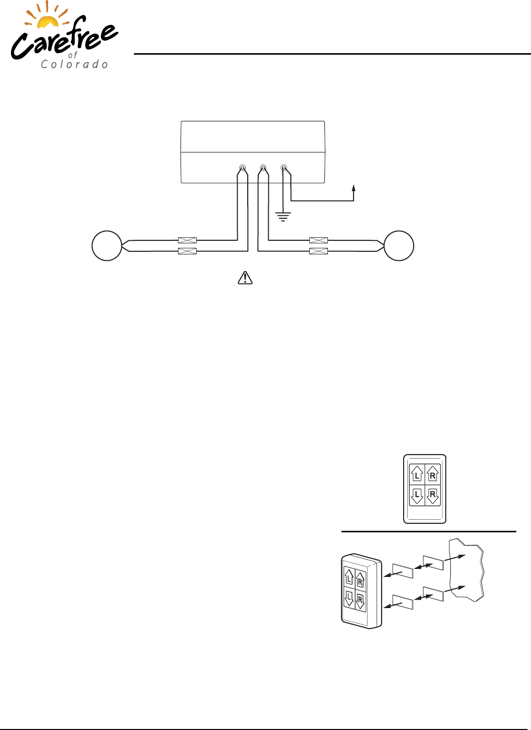
INSTALLING THE RECEIVER
Red
Black
+12VDC
M
Black
Red
M
Blue
White
Blue
White
Black
Red
LH
(Driver)
Visor
RH
(Passenger)
Visor
Remote Receiver
PV014
Chassis Ground
LEFT RIGHT 12VDC
CAUTION
• DO NOT CONNECT THE RECEIVER TO ANY POWER SOURCE OTHER THAN +12VDC.
• DO NOT ATTACH MORE THAN 2 VISOR MOTORS TO THE CONTROL BOX. DAMAGE TO THE RECEIVER MAY OCCUR.
• DO NOT MOUNT THE RECEIVER NEAR OR ON METAL SURFACES OR NEAR HEAT SOURCES.
1. Connect the wires as shown in the wiring diagram. The unit has 24” wires, if the unit is positioned farther from the
visor wires, the installer must splice an extension between the motor and the receiver.
NOTE: The receiver should be positioned within 10 feet or less of the approximate location that the transmitter
will be kept (i.e. on the driver’s side dash). The effective range of the transmitter is 10 feet.
2. Clean the back of the receiver and the mounting surface.
3. Remove one side of the release paper on the double sided tape and firmly press onto the back of the receiver.
Remove the second piece of release paper and firmly press the receiver onto the mounting surface.
4. Test the remote:
• Press the Left Down arrow then the Left Up arrow. The driver’s
side visor should lower then raise.
• Repeat for the passenger visor (if installed) using the Right
Down and Up arrows.
• If the visor moves in the opposite direction than the arrow,
reverse the motor leads of the visor.
5. Mount the remote:
• Clean the mounting surface for the remote.
• Remove the release paper from loop half of the Velcro and
attach to the back of the remote. Do not separate the hook and
loop at this time. Install both the upper and lower pieces.
• Remove the release paper from the hook halves of the Velcro
and firmly press the remote into the desired mounting position.
• Lift the remote. The Velcro halves should separate with the
hook halves remaining on the mounting surface and the loop
halves remaining on the remote.
Mounting
Surface
Velcro
Remote PV015
Loop Hook
UP
DOWN
LH Visor
UP
DOWN
RH Visor
FCC NOTE:
THE MANUFACTURER IS NOT RESPONSIBLE FOR ANY RADIO OR TV INTERFERENCE CAUSED BY
UNAUTHORIZED MODIFICATIONS TO THIS EQUIPMENT. SUCH MODIFICATIONS COULD VOID THE USER’S
AUTHORITY TO OPERATE THE EQUIPMENT.