C2 Development 30000003 2.4GHz low-power RF module (FULL MODULAR APPROVAL) User Manual CERTIFICATE OF COMPLIANCE
C2 Development, Inc. 2.4GHz low-power RF module (FULL MODULAR APPROVAL) CERTIFICATE OF COMPLIANCE
User Manual

C2 Development, Inc. 2.4GHz RF Module – 3000-0003 Page 1 of 6
2.4GHz RF Module
PN: 3000-0003
Date Version Revision Author
July 5, 2011 1 Initial Release CC / JJ
C2 Development, Inc. 2.4GHz RF Module – 3000-0003 Page 2 of 6
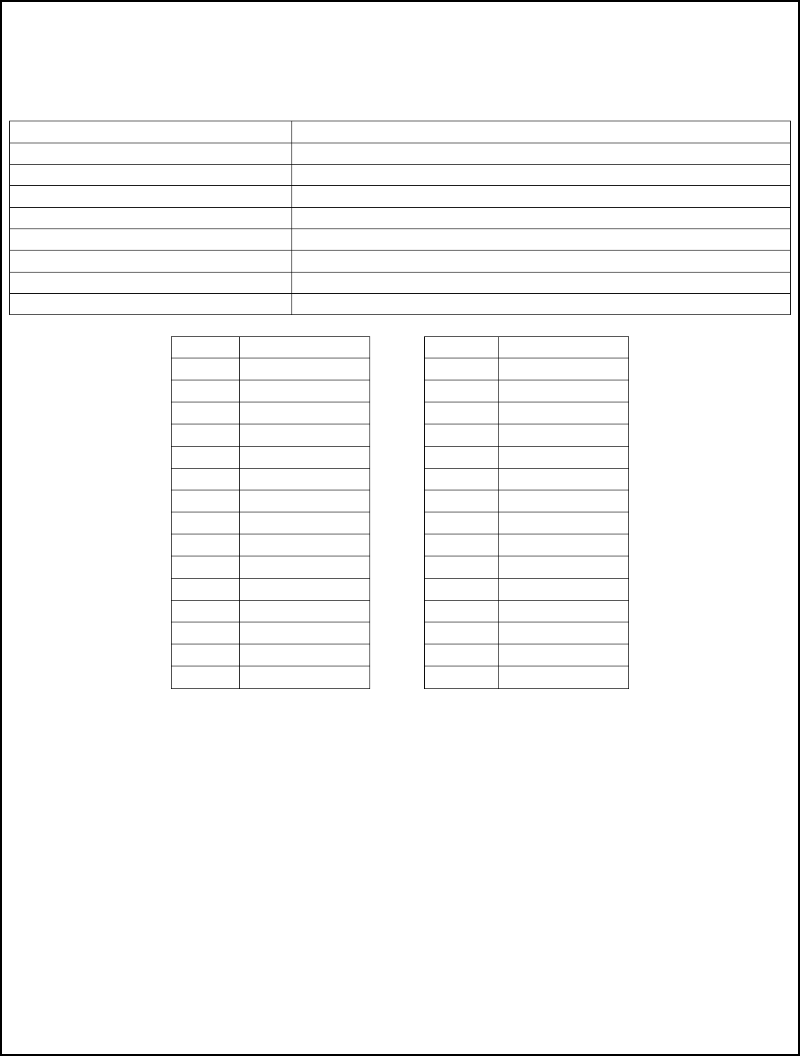
Technical Specifications
RF Characteristics
Minimum Carrier Frequency 2433 MHz
Maximum Carrier Frequency 2480 MHz
Rx Bandwidth 232.1 KHz
Channels 30
Modulation 2-FSK
Data Rate 15K Baud
Raw Packet Length 11 – 18 Bytes, variable
Payload 1 – 8 Bytes, variable
Tx Power +1 dBm, Fixed
Channel Frequency(MHz) Channel Frequency(MHz)
0 2433 15 2457.6
1 2435.2 16 2459.2
2 2436.8 17 2460.8
3 2438.4 18 2462.4
4 2440 19 2464
5 2441.6 20 2465.6
6 2443.2 21 2467.2
7 2444.8 22 2468.8
8 2446.4 23 2470.4
9 2448 24 2472
10 2449.6 25 2473.6
11 2451.2 26 2475.2
12 2452.8 27 2476.8
13 2454.4 28 2478.4
14 2456 29 2480
C2 Development, Inc. 2.4GHz RF Module – 3000-0003 Page 3 of 6
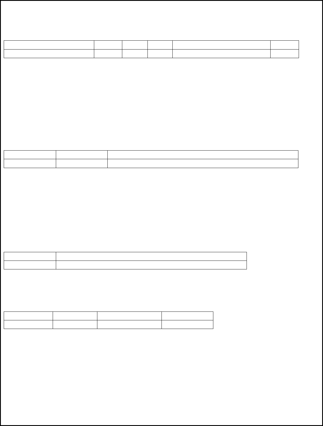
Communication Protocol
RF Packet Protocol (Tx and Rx)
4 Bytes 2 Bytes 1 Byte 1 Byte 1 – 8 Bytes 2 Bytes
Preamble Sync Length Node Payload CRC
Preamble – 4 Bytes of alternating 1’s and 0’s.
Sync – Two byte Sync word used to align data. Value is always 0xD391.
Length – Packet Length in bytes, equal to the length of the Payload + 1.
Node – Node Address. Composite Master/Slave ID. The Master ID is in the upper 4 bits and the
Slave ID is in the lower 4 bits. For Discovery Mode, this byte is set to 00.
Payload – The payload, 1 to 8 bytes.
CRC – 16 bit CRC starting with the Length byte and ending with the last payload byte.
UART Data Packet Protocol (Master Only)
Any data sent to the adapter via the UART Rx line must adhere to the following protocol:
1 Byte 1 Byte 1 to 8 Bytes, variable
Packet Length Slave ID Payload
Length – Total length of the packet in bytes (Payload + 1). The upper 4 bits always contain the
value 0xA0, and the lower 4 bits contain the byte length. Valid byte lengths are 0x01
through 0x08.
SlaveID – Destination of packet. The upper 3 bits always contain the value 0xA0, and the lower 5
bits define the Slave ID. Valid values are 1 through 31.
Payload – The payload, 1 to 8 bytes.
UART Data Packet Protocol (Slave Only)
Data that is sent out of the adapter via the UART Tx line is formatted as follows:
1 Byte 1 to 8 Bytes, variable
Payload Length Payload
Payload Length – Total length of the payload in bytes. Valid values are 1 though 8.
Payload – The payload data.
RF ACK Packet Protocol (Sent by Masters, Received and Sent by Slaves)
1 Byte 1 Byte 1 Byte 1 Byte
Packet Length Composite ID ACK Command Master’s ID
Packet Length – Packet Length, always set to 0x03.
Composite ID – The upper 4 bits contain the Master’s ID, and the lower 4 bits contain the Slave’s ID.
ACK Command – Always the value 0xA9.
Master’s ID - Master ID in lower 4 bits.

C2 Development, Inc. 2.4GHz RF Module – 3000-0003 Page 4 of 6
RF Discovery Packet Protocol
1 Byte 1 Byte 1 Byte 1 Byte 1 Byte 1 Byte
Packet Length Discovery ID Discovery Cmd New Master ID New Slave ID New Channel
Packet Length – Packet length, always set to 0x05.
Discovery ID – Composite Discovery ID, set to 0x00 in current versions.
Discovery Cmd – Discovery Command, always set to 0xAF.
New Master ID – The new ID of the Master that the Slave must use.
New Slave ID – The new ID that the Slave must use as its node address.
New Channel – The new channel frequency that the Slave must use for all future reception (1 - 29).
End User Programming
In order for two or more adapters to communicate, one adapter must be set up as a Master and all others (1
through 31) must be configured as slaves. After a reset, all modules are locked in a special mode, waiting for
Master/Slave programming. This mode is indicated by either Red or Green LEDs on, but not both. Pushing and
releasing the button will toggle between Red and Green.
STEP 1: Factory Reset Procedure
1) While Holding down the button, apply power to the adapter.
2) Continue to hold down the button for approximately 5 seconds, or until the both LEDs illuminate.
2) Release the button. The Red LED will be on and the Green LED goes off.
STEP 2: Master/Slave Setup Procedure
1) Pressing and releasing the button will toggle the LEDs. To setup an adapter as a Master, press and release
the button until the Green LED is on. To setup as a slave, press and release the button until the Red LED is on.
2) While the desired LED is on (Red=Slave, Master=Green), press and hold down the button for at least 5
seconds.
3) When both LEDs turn off, release the button. Both LEDs should now be on.
STEP 3: Discovery Mode Procedure
Discovery Mode links a single Master to one or more Slaves. Discovery Mode mjst be run immediately after
the Master/Salve Setup Procedure is complete. To run Discovery Mode:
1) Press and release the button on the Master wireless adapter. Both the Red and Green LEDs will flash.
2) Within 30 seconds, press and release the button on the LEFTMOST Slave adapter. Both the Red and Green
LEDs will flash.
3) After a few seconds, the Red LED will turn off and the Green LED will turn on at both adapters.
To configure multiple slaves, it is important that the slaves be set up in sequence. The LEFT MOST RF module
should be the FIRST Slave selected. To program additional slaves, press the button on the Master again,
followed by the button on the next Slave, going from left to right until all slaves are programmed.
Slave #1 Slave #2 Slave #31
Fixture ….
Module Module Module

C2 Development, Inc. 2.4GHz RF Module – 3000-0003 Page 5 of 6
At this point, all adapters have been programmed and are ready for use.
NOTE: After a Slave is programmed, the button no longer functions to run Discovery mode. The button
changed functionality and is now be used to view the Slave’s ID number. The procedure is:
1) Press the button on the Slave. All LEDs will go off. Release the button.
2) The Red LED will flash one or more times. The number of flashes indicates the Slave’s ID. For example, one
Flash = Slave ID #1, two flashes = Slave ID #2, and so on. In addition to this procedure, the controller firmware
will have a Slave Test menu selection which is easier to use and more convenient for the end user.
Note: In order to allow a slave to run Discovery Mode again, the slave must undergo the factory reset
procedure. This is done to prevent the user from accidently pressing a Slave’s button and reprogramming its
position in the lineup.
How Discovery Mode Works
1) The Master transmits a Discovery Packet. The packet is sent on Channel Frequency #0 (2433 Mhz) with a
Node Address of #00 (both of which are illegal values for normal operation). The Master then listens for a
response on the new Channel Frequency indicated in the packet. If no response is received within 500 ms (or
the response is not a Discovery Packet), the packet is transmitted over and over again. After 30 seconds, the
Master gives up.
2) The Slave sets itself to Receive mode on Channel Frequency #0 (2433 Mhz) with an address filter of #00,
listening for packets. If it does not receive a Discovery Packet within 30 seconds, it gives up.
3) Once the Slave receives the packet, it sets its Master ID, Slave ID, and Channel Frequency from the data in
the packet. It then returns the Discovery packet on the new Channel Frequency using the Master’s ID as the
node address. The Slave then exits Discovery Mode as the operation was successful.
4) Once the Master receives the packet from the Slave, it exits Discovery Mode and increments its internal
Slave ID counter it preparation for the next slave Discovery Mode operation.
ACK Operation
At least once per second, the Master sends the ACK packet to a slave. In multiple slave setups, the last slave
that received a normal data packet is chosen. The slave must respond within a specific time frame by
returning the ACK packet intact. If it does not, the Red LED flashes once for each lost packet.
Occasional or repeated flashing on the Red LED indicates packet loss. This is caused by radios nearing or
exceeding their range limit and/or electrical interference in the operating environment. If this condition
persists, running through Steps 1 through 3 again will choose a different channel and may alleviate the
problem.

C2 Development, Inc. 2.4GHz RF Module – 3000-0003 Page 6 of 6
FCC Warnings:
This device complies with Part 15 of the FCC Rules. Operation is subject to the following two conditions:
(1) This device may not cause harmful interference, and (2) this device must accept any interference received,
including interference that may cause undesired operation. Changes or modifications not expressly approved
by C2 Development could void the user’s authority to operate this equipment.
FCC ID: ZOM-30000003