C2 Therapeutics 1017 C2 CryoBalloon Ablation System Controller User Manual 303 Convention Way Suite 1
C2 Therapeutics C2 CryoBalloon Ablation System Controller 303 Convention Way Suite 1
Manual
PRT-1824 Rev 4 C2 Therapeutics, Inc. Page 1 / 6
C2 CryoBalloon™ Ablation System
Description
The C2 CryoBalloon™ Ablation System is used to destroy
unwanted tissue by application of extreme cold. The balloon
probe comes in contact with the wall of target tissue. Upon
activation by a physician using the Foot Pedal, the balloon
probe at the end of the Catheter is simultaneously cooled and
inflated with nitrous oxide, which ablates the unwanted tissue.
Nitrous oxide is fully contained within the balloon and the
system. The nitrous oxide gas exits through the proximal end
of the Catheter. The C2 CryoBalloon Ablation System is
designed for use in conjunction with a therapeutic endoscope
(3.7 mm working channel ID, 100 cm maximum working
length). The System is comprised of the following main
components:
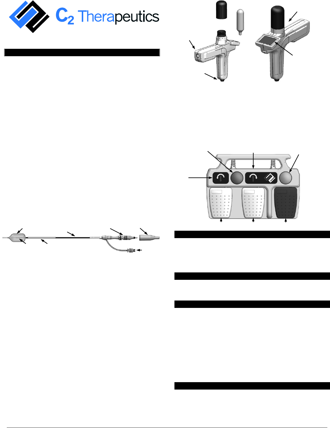
C2 CryoBalloon™ Catheter (see Figure 1) connects to the
Controller, which controls the operation of the Catheter
such as diffuser (sprayer) positioning and ablation
(nitrous oxide release). C2 CryoBalloon Catheter consists
of proximal Connector, Catheter Connector Cap, Catheter
Shaft, balloon probe, and protective sheath. The Catheter
is supplied sterile and is disposable after single patient
use.
Figure 1 – C2 CryoBalloon™ Catheter
C2 CryoBalloon™ Controller (see Figure 2) contains the
cartridge heater and the cryogen delivery valve, which is
controlled with the Foot Pedal. The Controller contains
diffuser radial and axial positioning features that are
controlled by the Foot Pedal. The Controller is powered
by 12VDC through the Foot Pedal and is supplied non-
sterile and is reusable. An LCD touch screen on the
Controller communicates system status and allows
dosimetry input.
C2 CryoBalloon™ Cartridge (see Figure 2) containing 36
grams of nitrous oxide. The Cartridge is installed into the
Controller and replaced as required per procedure. The
Cartridge is supplied non-sterile for single patient use.
Figure 2 – C2 CryoBalloon™ Controller &
C2 CryoBalloon™ Cartridge
C2 CryoBalloon™ Foot Pedal communicates the user
input to the Controller such as diffuser positioning,
ablation, and balloon deflation. The Foot Pedal is
powered by mains with an input voltage of 90 to
264VAC, 50-60Hz at 2A. The Foot Pedal is supplied non-
sterile and is reusable.
Figure 3 – C2 CryoBalloon™ Foot Pedal
Indications for Use
The C2 CryoBalloon™ Ablation System is intended to be
used as a cryosurgical tool in the field of general surgery,
specifically for endoscopic applications, to include ablation of
Barrett’s Esophagus with dysplasia.
Prescription Use
Caution: USA federal law restricts this device to sale by or on
the order of a physician.
Contraindications
There are no known contraindications for use of this device.
Reported contraindications for endoscopic use of cryosurgical
ablation devices include:
Pregnancy
Significant ulceration of the target tissue
Narrowing of the access lumen that precludes advancing
the C2 CryoBalloon Catheter to the site of ablation
Target tissue varices at risk for bleeding
Prior Heller myotomy
Warnings
The C2 CryoBalloon™ Catheter is intended for single
patient use only. Do not resterilize or reuse.
Resterilization or reuse may compromise device
performance and increase the risk of cross contamination
Controller
Cap
Cartridge
Insertion port
for Catheter
Cable
Receptacle
Controller
with Cap
Control
Panel
Mode Select
Button
Deflate
Button
Clockwise Rotate/
Distal Translation Indicator
Counter
Clockwise
Rotate/
Proximal
Translation
Indicator
Ablation/Puff Pedal
Pedal 2
Pedal 1
Connector
(Proximal End)
Luer Activated
Valve
Connector
Cap
Catheter
Shaft
Protective
Sheath
Balloon Probe
(Distal End)
Diffuser
PRT-1824 Rev 4 C2 Therapeutics, Inc. Page 2 / 6
due to inappropriate reprocessing, resulting in damage to
the device or patient injury.
If there is resistance during manipulation of the Catheter,
determine the cause of the resistance before proceeding.
Use the device prior to the Use By date specified on the
package.
If the Catheter shaft is bent or kinked, discard and replace
the device. Do not use or attempt to straighten. This may
result in damage to the device or patient injury.
Use only the C2 CryoBalloon™ Cartridge. Device
operation will be impaired if other refrigerants or gasses
are used.
The pressure inside the C2 CryoBalloon™ Cartridge is 50
atm. Carefully remove the Cartridge to avoid unintended
release of residual cryogenic fluid from the Controller.
The cryogenic fluid may freeze the skin.
Do not inhale nitrous oxide from the cryogen cartridge.
Inhalation may be dangerous to your health.
WARNING: No modification of this equipment is
allowed.
WARNING: To avoid risk of electric shock, this
equipment must only be connected to a supply mains with
protective earth.
Precautions
A thorough understanding of the principles, clinical
applications and risks associated with ablation of
unwanted tissue is necessary before using this product.
Use of the C2 CryoBalloon™ Ablation System for
procedures other than those indicated in these instructions
is not recommended.
Multiple ablations at the same site may result in deeper
than intended ablation. In the event that adjacent ablations
are desired, wait until visible ice is no longer present near
the adjacent ablation area.
The C2 CryoBalloon™ Ablation System is designed to be
used in patients with diameters measuring 20 mm to 30
mm. Ablation in larger or smaller lumens is not
recommended.
Do not use if package is open or damaged.
Prior to use, examine for defects such as breaks, tears,
bends or kinks. Do not use if defects are found.
Do not pre-inflate or pre-test balloon prior to introduction
through endoscope or Sidecar.
Do not attempt to refold balloon into the protective
sheath.
If the Control Panel on the C2 CryoBalloon™ Controller
does not illuminate after it is plugged into the Foot Pedal
interconnect cable, replace the Controller.
After the procedure, straighten the distal end of the
endoscope as much as possible prior to removing the C2
CryoBalloon™ Catheter from the endoscope. Any excess
bends of the endoscope will increase the resistance during
withdrawal. If there is excessive resistance, remove the
endoscope and Catheter as a unit.
Under normal use, the balloon probe is the only element
of the C2 CryoBalloon™ Ablation System that will be
0oC or colder. If any of the user accessible components
are excessively cold, discontinue use.
The C2 CryoBalloon™ Controller heater assembly
contains a thermal protector to protect against
temperatures in excess of 100°C. If this temperature is
reached, the thermal protector will render the Controller
unusable.
The C2 CryoBalloon™ Controller is considered IPX0 (no
protection, do not immerse in liquids) for ingress
protection against liquids.
The C2 CryoBalloon™ Foot Pedal meets IPX6
(protection against water rinsing, do not immerse in
liquids) for ingress protection against liquids.
The C2 CryoBalloon™ Controller should not be used in
the presence of flammable anesthetics.
In the event that the C2 CryoBalloon Controller is
dropped, discard and replace it.
Foot Pedal Preparation
1. Open the Foot Pedal package and remove the Power
Cable and Foot Pedal.
2. Plug the Power Cable into the Foot Pedal power supply.
3. Plug the Power Cable plug into the mains power source.
4. Position the Foot Pedal at the desired location.
Controller Preparation
5. Open the Controller package and remove the Controller
and Controller Cap. Open the Cartridge package and
remove a Cartridge.
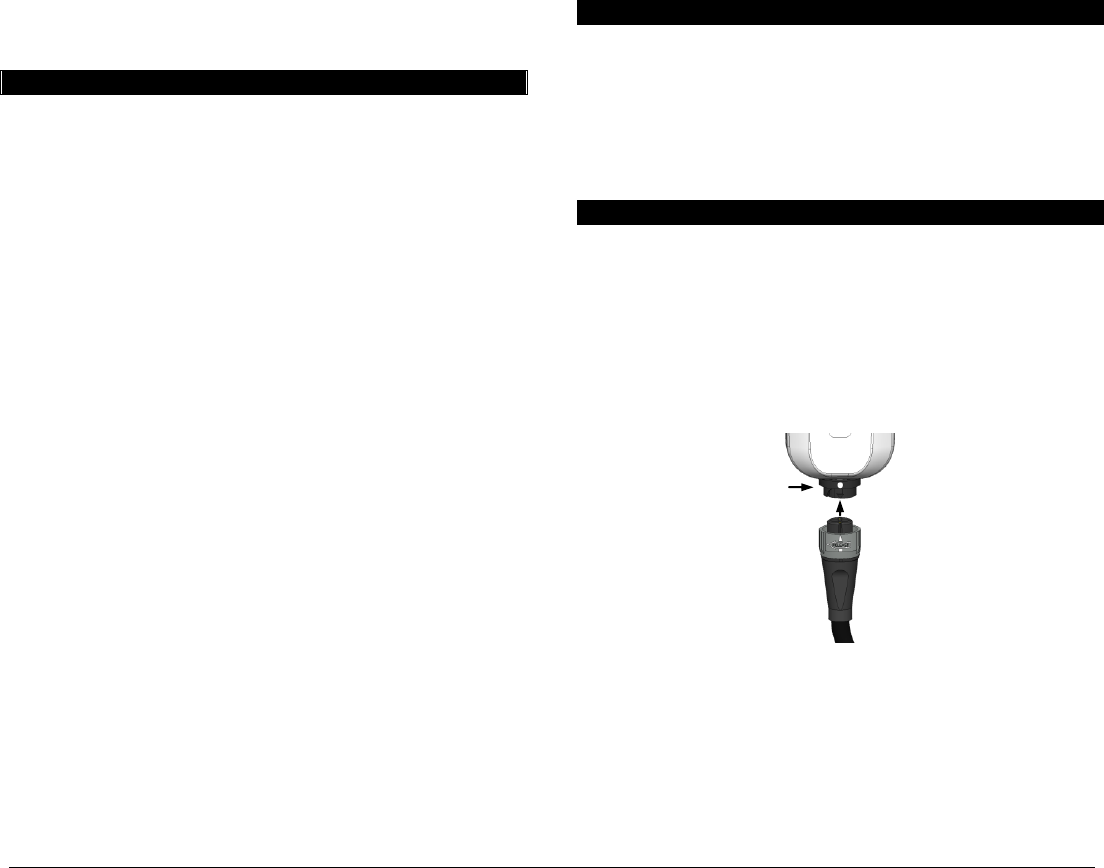
6. Plug the Interconnect Cable of the Foot Pedal into the
Controller to power it on. Confirm the cable is securely
attached. (Figure 4)
Figure 4 – Interconnect Cable to Controller
7. Insert the round end of the Cartridge into the Controller
Cap (press firmly).
Caution: Use only C2 CryoBalloon™ Cartridges.
8. Insert the Controller Cap and Cartridge into the Controller
and rotate the Controller Cap clockwise until it stops. This
action breaks the seal on the Cartridge.
Interconnect
Cable
Cable Receptacle
Controller
PRT-1824 Rev 4 C2 Therapeutics, Inc. Page 3 / 6
Catheter Insertion
9. Open the package and remove the Catheter.
Caution: Do not remove the Catheter Connector Cap
(proximal) or Protective Sheath (distal) until instructed.
10. Remove the biopsy valve cap and insert the Catheter
Balloon Probe constrained within the Protective Sheath
into the biopsy valve of the endoscope (3.7 mm ID
minimum; 100 cm length maximum).
Caution: Do not pre-inflate or pre-test the balloon. Do not
attempt to refold the balloon into the Protective Sheath. If
the balloon is not constrained within the Protective Sheath
prior to use, discard and replace the Catheter.
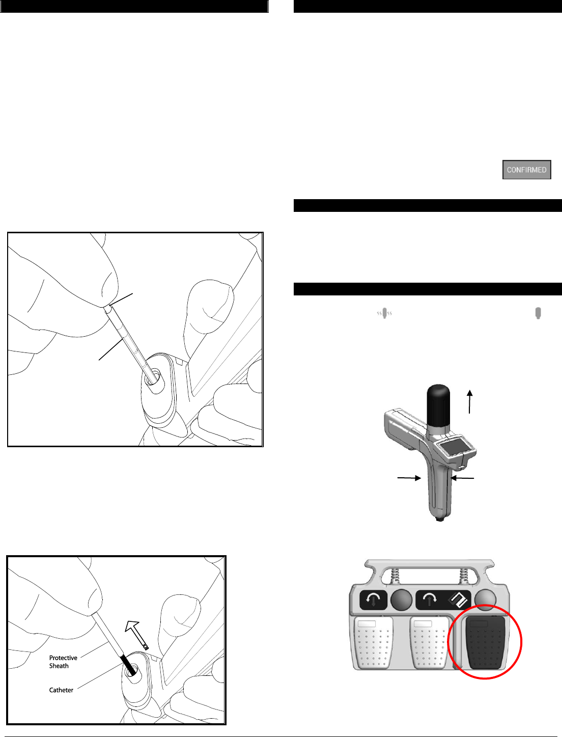
11. Grasp the Catheter close to the endoscope and advance
the Catheter through the Protective Sheath and through
the biopsy valve (Figure 5).
Figure 5 – Insert Catheter into the Biopsy Valve
12. Continue advancing the Catheter until the balloon exits
the endoscope.
Caution: Visualize the Catheter tip as it exits the endoscope.
13. Withdraw the Protective Sheath from of the biopsy valve
and slide proximally onto the Catheter shaft (Figure 6).
Figure 6 – Slide the Protective Sheath Proximally
Catheter Positioning
14. Position the distal end of the endoscope approximately 2
to 3 cm proximal to the ablation site.
15. Advance the Catheter out of the endoscope until the black
Catheter shaft (proximal to the balloon) is visible. Retract
the Catheter into the endoscope until there is slight
resistance (balloon contacting endoscope).
16. Remove and discard the Catheter Connector Cap.
17. Insert the Catheter Connector into the Controller. An
audible “click” will be heard. Lightly tug on the
Connector and Controller to confirm a secure connection.
18. After the Catheter has been connected, press
to verify that a Catheter has been connected.
Ablation Dosimetry Selection
19. Using the Controller Control Panel, select the desired
ablation dosimetry. Refer to specific dosimetry
information in the Catheter Instructions For Use (IFU).
The System is ready for ablation after the ablation
dosimetry has been selected.
Balloon Pre-Inflation and Ablation
20. When the Cartridge is at operational pressure, the orange
Standby Icon will change to a blue Ready Icon ,
and an audible beep will sound.
21. Hold the Controller upright with the Controller Cap
pointing vertically (towards the ceiling). Ablation will be
disabled if the Controller orientation is incorrect.
22. Depress and quickly release the Foot Pedal Ablation pedal
(circled below) to pre-inflate the balloon.
Note: This will deliver a small amount of cryogen that inflates
the balloon so that it is in contact with the tissue.
Protective
Sheath
Catheter
Point towards
the ceiling
Grip here
PRT-1824 Rev 4 C2 Therapeutics, Inc. Page 4 / 6
Caution: Do not occlude the exhaust ports during ablation.
23. Visualize the ablation site through the balloon. Retract or
advance the Catheter for optimal positioning.
24. To visualize the target tissue area, press and quickly
release the Ablation pedal (puff). This will deliver a small
amount of cryogen to the targeted tissue area. The tissue
will turn white due to momentary freezing.
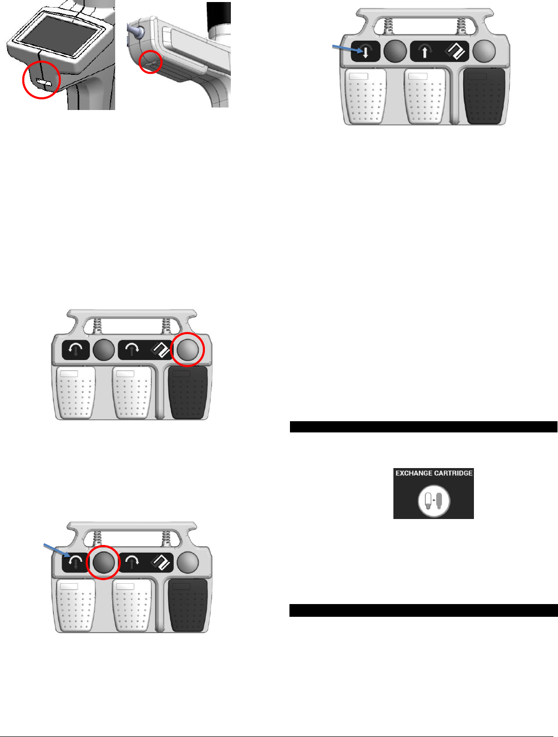
25. To reposition the balloon proximally or distally press the
Deflate button on the Foot Pedal (circled below), or
deflate the balloon by attaching a 30 mL syringe to the
Luer Activated Valve on the Catheter Connector and
drawing vacuum to deflate the balloon. Reposition the
balloon and repeat step 22 through step 24 to confirm the
position.
26. To Rotate the diffuser, select the Rotation mode with the
Mode Select Button on the Foot Pedal (circled below),
and use the grey pedals to rotate the diffuser clockwise or
counter -clockwise. The rotational arrows will illuminate
to indicate to user that Foot Pedal is in Rotation mode.
27. To adjust the Axial position of the diffuser, select the
Translate mode on the Foot Pedal with the Mode Select
Button, and use the grey pedals to move the diffuser
distally or proximally. The axial arrows will illuminate to
indicate to user that Foot Pedal is in Translate mode.
28. Repeat Step 24 to verify position.
Note: During ablation, the inflated balloon remains stationary.
Note: During ablation, the Focal catheter diffuser remains
stationary for the duration of the selected dosimetry time.
The diffuser for all other catheter configurations travels
proximally at the selected dosimetry rate.
29. To perform ablation, press and hold the Ablation pedal on
the Foot Pedal. Cryogen is continuously delivered from
the diffuser for the entire ablation duration. During
ablation, the Control Panel will indicate that Treating is
in process, and a beep sounds every second.
Caution: To stop the flow of cryogen during ablation prior to
the full ablation duration, release the Ablation pedal.
30. Cryogen flow will automatically stop after the user
selected duration has elapsed.
31. An extended audible sound signals when ablation is
complete. Release the ablation pedal.
Note: The balloon inflates to approximately 4.5 psig (0.3
ATM). The balloon pressure cannot be altered by the
user.
Exchange Cartridge
32. Additional Ablations can be performed with the current
cartridge until the Exchange Cartridge prompt appears.
33. To exchange the Cartridge, by slowly rotate the
Controller Cap counterclockwise. Any remaining nitrous
will exhaust. Dispose of the used Cartridge.
34. Install a new Cartridge by following Steps 7 to 8.
35. Perform additional ablation by following Steps 20 to 31.
Catheter Withdrawal
36. Prior to withdrawal, return the diffuser to the distal most
position and straighten the distal end of the endoscope as
much as possible. Any excess bend on the endoscope will
increase the resistance during withdrawal of the catheter.
37. Follow one of the two techniques to withdraw the
Catheter into the endoscope:
a) Press and hold the Deflate button on the Foot Pedal
and withdraw the Catheter into the endoscope.
Lights indicate
rotation mode
Lights indicate
translate mode

PRT-1824 Rev 4 C2 Therapeutics, Inc. Page 5 / 6
Release the button when the Catheter has been fully
withdrawn into the endoscope. Or,
b) Attach a 30mL syringe to the luer-activated valve
that is attached to the Catheter. Draw a vacuum to
fully deflate the balloon. Maintain the vacuum and
slowly retract the Catheter into the endoscope.
Caution: If there is excessive resistance, remove the
endoscope and Catheter as a unit.
38. Press on the Control Panel, to detach the Catheter
from the Controller. Dispose of the Catheter according to
standard hospital guidelines for the disposal of medical
waste.
39. When the procedure has been completed, remove the
Cartridge from the Controller and dispose of the
Cartridge.
40. Clean/disinfect Controller and clean Foot Pedal and store
according to Operation, Storage and Disposal instructions.
Troubleshooting
If a fault condition occurs, the LCD touch screen on the
Controller will display an Error Description with
recommended Corrective Action. If the Corrective Action
displayed does not resolve the fault condition, do not use the
system. Contact C2 Therapeutics, Inc.
Cleaning and Disinfection
The reprocessing instructions are based on recommendations
found in the “Guideline for Disinfection and Sterilization in
Healthcare Facilities, 2008” by the Centers for Disease
Control (CDC).
This section provides guidelines for cleaning and disinfecting
the C2 CryoBalloon™ Controller. The Controller has a reuse
life of 1 year. Use EPA-registered disinfectant wipes and the
provided brushes/swabs wetted by EPA-registered disinfectant
spray.
Caution: The Controller is rated for IPX0 (it has no protection
against ingress of liquids) – do not allow any fluid to enter the
Controller.
1. Remove the Controller Cap and soak it in warm water for
at least 5 minutes.
2. Wipe all accessible surfaces on the Controller and the
Cap. Repeat until visible soils are removed.
3. Spray the Controller to adequately wet the external
surfaces. Brush all the external surfaces and swab the
inner exhaust ports.
Caution: Do not spray liquid disinfectant directly into the
catheter insertion port, the receptacle for the cartridge, and the
cable receptacle.
4. Leave the Controller undisturbed for at least 4 minutes.
5. Wipe the Cap and all accessible surfaces on the
Controller. Use multiple wipes.
6. Allow the Controller assembly to dry prior to use.
This section provides guidelines to clean the C2
CryoBalloon™ Foot Pedal. The Foot Pedal has a reuse life of
3 years.
Caution: The Foot Pedal is rated for IPX6 (protection against
splashing of liquids; no protection against submersion) – do
not fully submerge the Foot Pedal.
1. Clean any visible soils with a mild soap and water
solution if necessary. Wipe clean.
2. Allow the Foot Pedal to dry prior to use.
Operation, Storage and Disposal
Operate and store the C2 CryoBalloon™ Ablation System as
follows:
Controlled room temperature environment with ambient
temperature from +10°C to +40°C
Relative humidity from 30% to 75%
Atmospheric pressure from 700 to 1060 hPa
Dispose of the C2 CryoBalloon™ System components in
accordance with standard hospital guidelines and local codes
for the disposal of medical waste and electronic waste.
EMC Compliance and Warning Statement
This equipment has been tested and found to comply with the
limits of the standard for medical devices, IEC 60601-1-2. The
limits are designed to provide reasonable protection against
harmful interference in a typical medical installation. This
equipment generates, uses and can radiate radiofrequency
energy, and, if not installed and used in accordance with the
manufacturer’s instructions may cause harmful interference to
other devices in the vicinity. However, there is no guarantee
that interference will not occur in a particular installation. If
this equipment causes interference with other devices, which
may be determined by turning the equipment off and on, the
user should notify the hospital safety personnel and try to
correct the interference by one or more of the following
measures:
Reorient or relocate the device receiving the interference.
Increase the separation between the equipment.
Consult the manufacturer for help.
FCC Compliance and Warning Statement
Changes or modifications not expressly approved by the
manufacturer could void the user’s authority to operate the
equipment.
NOTE: This equipment has been tested and found to comply
with the limits for a Class A digital device, pursuant to part 15
of the FCC Rules. These limits are designed to provide
reasonable protection against harmful interference when the
equipment is operated in a commercial environment. This
equipment generates, uses, and can radiate radiofrequency
energy and, if not installed and used in accordance with the
instruction manual, may cause harmful interference to radio
communications. Operation of this equipment in a residential
area is likely to cause harmful interference in which case the
user will be required to correct the interference at their own
expense.
EMC Guidance and Declaration
The CryoBalloon Ablation System is intended for use in the
electromagnetic environments described in the tables below.
The customer or user of the system should assure that is used
in such an environment
PRT-1824 Rev 4 C2 Therapeutics, Inc. Page 6 / 6
ELECTROMAGNETIC IMMUNITY
Immunity
Test
Test
Level
Compliance
Level
Electromagnetic environment
guidance
Electrostatic
Discharge
(ESD)
IEC 61000-4-
2
± 6 kV
contact
± 8 kV air
± 6 kV
contact
± 8 kV air
Floors should be wood, concrete
or ceramic tile. If floors are
covered with synthetic material,
the relative humidity should be at
least 30%
Power
Frequency
(50/60 Hz)
magnetic
field
IEC 61000-
4-8
3 A/m
3 A/m
Power frequency magnetic fields
should be at levels characteristic
of a typical location in a typical
commercial hospital environment
Radiated
RF
IEC 61000-
4-3
3 V/m
80 MHz to
2.5 GHz
3 V/m
80 MHz to
2.5 GHz
Portable and mobile RF
communications equipment should be
used no closer to any part of the
CryoBalloon Ablation Controller, than
the recommended separation distance
calculated from the equation applicable
to the frequency of the transmitter.
The recommended separation distances
calculations can be calculated as
follows:
( Mhz)
( Mhz)
Field strengths from fixed RF
transmitters, as determined by an
electromagnetic site survey,a should be
less than the compliance level in each
frequency range.b
Interference may occur in the vicinity
of the equipment marked with the
following symbol:
a Field strengths from fixed transmitters, such as base stations for radio
(cellular/cordless) telephones and land mobile radios, amateur radio, AM and
FM radio broadcast and TV broadcast cannot be predicted theoretically with
accuracy. To assess the electromagnetic environment due to fixed RF
transmitters, an electromagnetic site survey should be considered. If the
measured field strength in the location in which the system is used exceeds the
applicable RF compliance level above, the system should be observed for
normal operation. If abnormal performance is observed, additional measures
may be necessary, such as re-orienting or relocating the Controller.
b Over the frequency range 150kHz to 79MHz, field strength should be less
than 3 V/m.
ELECTROMAGNETIC EMISSION
Emission Test
Compliance
Electromagnetic environment guidance
RF Emissions
CISPR 11
Group 1
The system uses RF energy only for its
internal function. Therefore, its RF
emissions are very low and not likely to
cause any interference in nearby electronic
equipment.
Class B
The system is suitable for use in all
establishments, domestic establishments
and those directly connected to the public
low-voltage power supply network that
supplies buildings used for domestic
purposes.
The C2 CryoBalloon™ Ablation System is intended for use in
an electromagnet environment in which radiated
radiofrequency (RF) disturbances are controlled. The
Controller part of the system is the only electronic component
of the system; therefore, the distances described below only
apply to the Controller. The customer or user of the system
can help prevent electromagnetic interference by maintaining
a minimum distance between portable and mobile RF
communications equipment (transmitters) and the Controller
as recommended below, according to the maximum output
power of the communications equipment.
Recommended separation distances between portable and mobile
communications systems and the CryoBalloon Ablation Controller
Rated Max
Output of
Transmitter
(watts)
Separation distance according to frequency of the
transmitter (meters)
150kHz-79Mhz
d=1.2
80MHz-799Mhz
d=1.2
800MHz-2.5GHz
d=2.3
0.01
0.12
0.12
0.23
0.1
0.38
0.38
0.73
1
1.2
1.2
2.3
10
3.8
3.8
7.3
100
12
12
23
For transmitters rated at a maximum output power not listed above, the
recommended separation distance (d) in meters (m) can be estimated using the
equation applicable to the frequency of the transmitter, where P is the
maximum output power rating of the transmitter in watts according to the
transmitter manufacturer.
NOTE: These guidelines may not apply in all situations. Electromagnetic
propagation is affected by absorption and reflection from structures, objects,
and people.
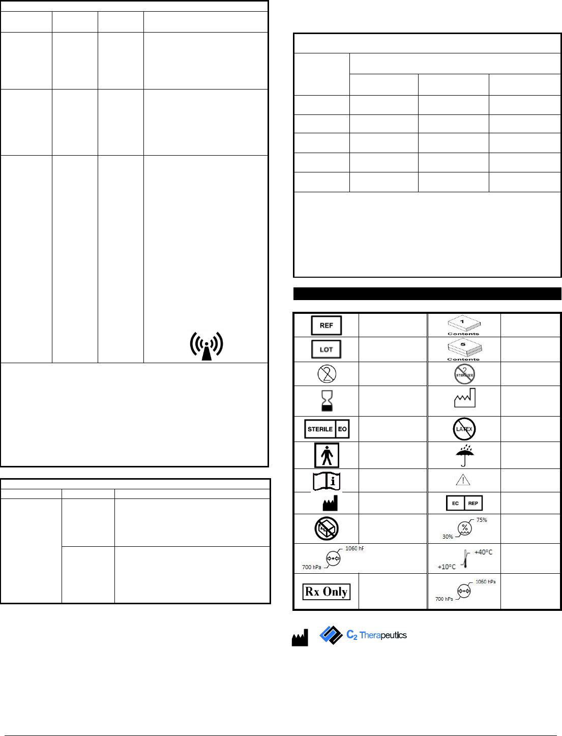
Labeling Symbol Key
Warranty
Catalog number
1 unit
Lot number
5 units
Single patient use
Do not resterilize
Expiration date
Date of Manufacturer
Sterilized by ethylene
oxide gas
This product is not
manufactured with
natural rubber latex
Type BF applied part
Keep dry
Consult instructions for
use
Caution See
Warnings
Manufacturer
Authorized
European
Representative
Do not use if package
is opened or damaged
Store at 30% to
75% RH (relative
humidity)
Store at 700 to 1060
hPa (hectopascals)
atmospheric pressure
Store at +10C to
+40C
Caution: USA Federal
law restricts this device
to sale by or on the
order of a physician
Store at 700 to
1060 hPa
(hectopascals)
atmospheric
pressure
C2 Therapeutics, Inc
303 Convention Way, Suite 1
Redwood City, CA 94063 USA
+1-866-979-5022