CAD Audio TX4000 Wireless Microphone User Manual
CAD Audio, LLC Wireless Microphone
User manual
CAD Audio
6573 Cochran Rd., Bldg.I Solon, OH 44139 U.S.A.
Tel: (440) 349-4900 Fax: (440) 248-4904
Sales: 800-762-9266 www.cadaudio.com
©2017 CAD Audio Part No. 62267-83- 00 Jan2017
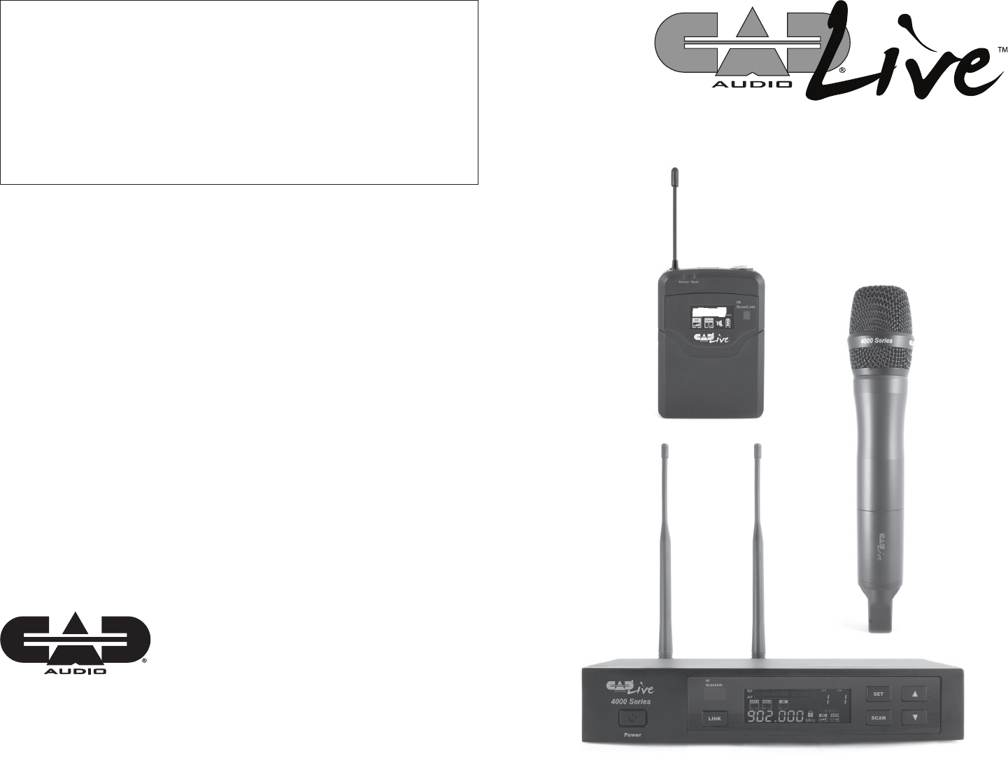
4000 Series
Digital Wireless
Microphone System
Manual and
Quick Start-up Guide
Two-Year Limited Warranty
CAD Audio hereby warrants that this product will be free of defects in material and workmanship for a
period of two years from the date of purchase. In the unlikely event that a defect occurs CAD Audio will,
at its option, either repair or replace with a new unit of equal or greater value. Retain proof of purchase to
validate the purchase date and return it with any warranty claim.
This warranty excludes exterior nish or appearance, damage from abuse, misuse of the product, use
contrary to CAD Audio’s instructions or unauthorized repair. All implied warranties, merchantability, or tness
for a particular purpose is hereby disclaimed and CAD Audio hereby disclaims liability for incidental, special
or consequential damages resulting from the use or unavailability of this product.
This warranty gives you specic legal rights and you may have other rights that vary from state to state.
Some states do not allow the exclusion or limitation of incidental or consequential damages or limitations on
how long an implied warranty lasts, so the above exclusions and limitations may not apply to you.
Note: No other warranty, written or oral is authorized by CAD Audio.
Individuals with cardiac pacemakers and other similar medical devices should consult with their
physician before using any RF devices. Though the output level of this wireless system is below 50
milliwatts, the proximity of the transmitter to the implant device could pose a threat.
As with any wireless product, environmental conditions can reduce or in some cases prohibit a
successful connection between the transmitter and the receiver.
This device complies with Part 15 of the FCC Rules. Most users of CAD Audio wireless products in
the United States do not need a license for operation. However, the rules for unlicensed operation
state that this device must not cause harmful interference, and must accept any interference received,
including interference that may cause undesired operation. Wireless products meeting CAD factory
standards adhere to these rules. The FCC reserves the right to change these rules at any time. For
more information contact the FCC at 1-888-CALL-FCC (TTY: 1-888-TELL-FCC) or visit the FCC’s wireless
microphone website at:
www.fcc.gov/cgb/wirelessmicrophones
This device complies with Industry Canada licence-exempt RSS standard(s). Operation is subject to the
following two conditions: (1) this device may not cause interference, and (2) this device must accept
any interference, including interference that may cause undesired operation of the device.
Under Industry Canada regulations, this radio transmitter may only operate using an antenna of a type
and maximum (or lesser) gain approved for the transmitter by Industry Canada. To reduce potential
radio interference to other users, the antenna type and its gain should be so chosen that the equivalent
isotropically radiated power (e.i.r.p.) is not more than that necessary for successful communication.
Conformément à la réglementation d’Industrie Canada, le présent émetteur radio peut fonctionner
avec une antenne d’un type et d’un gain maximal (ou inférieur) approuvé pour l’émetteur par Industrie
Canada. Dans le but de réduire les risques de brouillage radioélectrique à l’intention des autres
utilisateurs, il faut choisir le type d’antenne et son gain de sorte que la puissance isotrope rayonnée
équivalente (p.i.r.e.) ne dépasse pas l’intensité nécessaire à l’établissement d’une communication
satisfaisante.
Le présent appareil est conforme aux CNR d’Industrie Canada applicables aux appareils radio exempts
de licence. L’exploitation est autorisée aux deux conditions suivantes : (1) l’appareil ne doit pas
produire de brouillage, et (2) l’utilisateur de l’appareil doit accepter tout brouillage radioélectrique subi,
même si le brouillage est susceptible d’en compromettre le fonctionnement.
The CADLiveTM 4000 Series includes the following features:
• True Diversity to minimize multipath interference
• Frequency agile operation for maximum frequency plan exibility
• ScanLink™ technology for instantaneous and automatic channel conguration
• CADTone™ Body Pack input – Optimized Impedance interface -
Hi-Z for Guitar and Lo-Z for mic
• Metal construction Handheld Transmitter equipped with CADLive™D90 capsule
• High Contrast LCD displays on TX and RX
• Transmitters feature 1mW power adjustment to aid in multiple system
applications
• Dynamic Range > 115dB
• AA Batteries with up to 15 Hrs of battery life
• Systems ship with rack ears single/dual BNC relocation kit and
durable carry case
• BodyPack systems include miniature E19 Earworn, E29 Lav, WXGTR guitar cable
• XLR and ¼" outputs on receiver
61
Startup Guide
1. Install new high quality alkaline batteries into transmitter, observing proper polarity.
2. Power up receiver by holding power button for one second.
3. Hold the SET button for one second to unlock the receiver menu.
4. Hold the SCAN button for one second to activate the ScanLinkTM environmental
frequency analysis, which automatically selects a clear operating frequency.
5. Turn on the transmitter by holding the power button for one second.
6. Open the battery compartment to reveal the IR node.
7. Press the LINK button (note the IR node will illuminate). Align the two IR nodes
(transmitter and receiver) at a distance of 4"-12" (ambient room light can affect
distance) for a few seconds while the receiver updates the transmitter. Your
system is now ScanLink'd.
Accessing Advanced Features (SET button)
All advanced features are accessed by holding the “SET” button for one second to
unlock the menu. Press the “SET” button to advance through menu items. Menu
items may be adjusted using arrow keys.
1. Manually Select Frequencies
GR (frequency group)
CH (channel)
2. Receiver Squelch Level
SQL (used to reduce sensitivity to competing RF by sacricing operating distance)
3. Transmitter Power
TX SET RF (higher power increases operating distance, lower power improves
simultaneous usage)
4. Transmitter audio gain
TX SET GAIN (lower gain may be used as needed for louder performers)
5. Receiver Output Volume
VOL (may be reduced if audio signal overloads mixer)
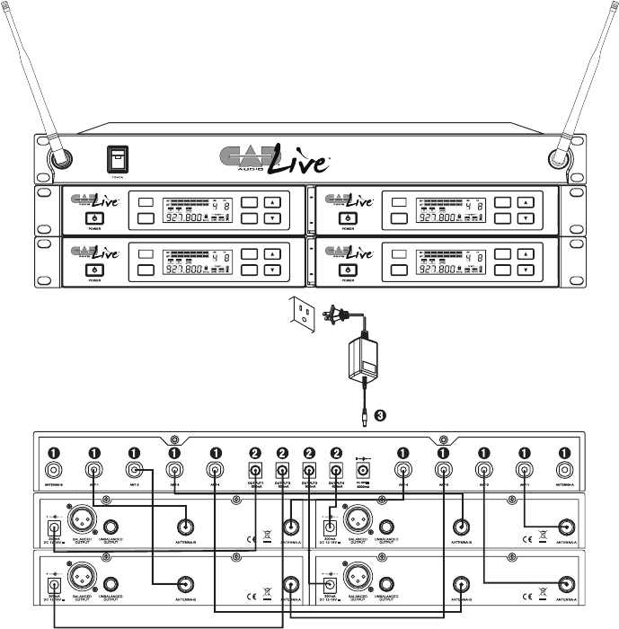
DA4090 DISTRIBUTION AMPLIFIER
LINK
SET
SCAN
IR
ScanLink
LINK
SET
SCAN
IR
ScanLink
LINK
SET
SCAN
IR
ScanLink
LINK
SET
SCAN
IR
ScanLink
Using the DA4090 Distribution Amplier to Simplify
Multiple-System Installations
1. BNC 50 ohm cable.
2. Power cable.
3. Power adapter.
2
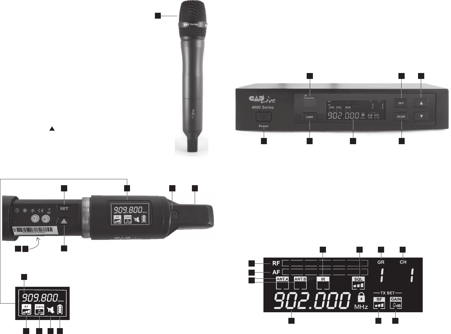
Handheld TX4000 Transmitter
1. CADLive D90 supercardioid
dynamic capsule.
2. Enclosed transmitting antenna.
3. Power/Mute button. Hold for power,
press for mute.
4. High-contrast display
a) Operating frequency
b) RF power indicator
c) Transmitter audio gain indicator
d) Mute indicator
e) Battery strength indicator
5. SET button. Unlocks advanced
features.
6. SELECT button. Use to adjust
advanced feature menu items.
7. IR node for Scan-LinkTM
8. Battery compartment. Use only high quality
AA alkaline batteries. Observe polarity.
1
25
7
4
8
other side
a
b c d e
3
6
Receiver RX4000 (Front)
1. Power button.
2. IR ScanLink node. Use for linking transmitter and receiver.
3. LINK button. Use to initiate TX-RX link.
4. SET button. Unlocks advanced features.
5. SCAN button. Use to initiate environmental frequency analysis.
6. UP and DOWN buttons. Use to adjust advanced feature
menu items.
1 7
2 4
3
6
7. High-Contrast display.
a) Multi-segment RF signal strength meter.
b) Multi-segment AF signal level meter.
c) ANT.A/ANT.B diversity indicator.
d) IR indicates active IR communication.
e) SQL squelch level indicator.
f) GR CH group and channel indicator.
g) Operating Frequency.
h) TX SET RF indicates transmitter RF power setting.
i) TX SET GAIN indicates transmitter audio gain setting.
g
a
b
d e
c
f f
h i
5
5
3 4
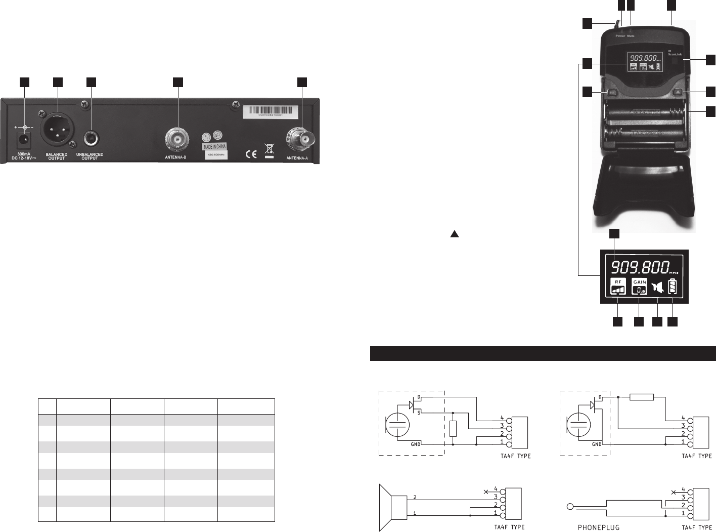
Interfacing to CADTone TB4M-type input connector
3k3
10 k
3k3
3k3
3k3
3-wire type electret mic
Dynamic mic
2-wire type electret mic
Instrument
Bodypack TX4010 Transmitter
1. Transmitting antenna
2. Power indicator
3. Power/Mute button: hold for
power, press for mute.
4. CADTone TB4M-type audio input
connector.
5. High-contrast display
a) Operating frequency
b) RF power indicator
c) Transmitter audio gain
indicator
d) Mute indicator
e) Battery strength indicator
6. SET button. Unlocks advanced
features.
7. IR node for ScanLink
8. SELECT button. Use to adjust
advanced feature menu items.
9. Battery compartment. Use only
high quality AA alkaline batteries
observing proper polarity.
2
1
3
8
9
4
5
6
a
b c d e
7
Receiver RX4000 (Rear)
1. DC power input jack. 12-18VDC, 300mA min, center positive.
2. XLRM-type low-impedance balanced audio output.
3. 1/4" [6.35mm] high-level unbalanced ouput
4. BNC 50 ohm antenna inputs.
Specications 4000 Series
Frequency Range ........................................................ T Band 903.55 - 927.65 MHz
Frequency Response .................................................................40Hz - 15kHz
Dynamic Range ...................................................................................>115dB
Battery Life
.................................................................................Up to 15 Hrs
Dimensions
....................................................... 17" [43.2cm] x 12" [30.5cm]
x 4" [10.2cm]
Weight
.......................................................................................... 5lbs [2.3kg]
1 2 3 4 4
CH Group 1 Group 2 Group 3 Group 4
1 903.550 904.050 905.150
2 906.550 904.800 907.550 908.950
3 908.300 906.250 910.300 912.000
4 910.500 909.800 912.900 913.400
5 913.900 914.400 915.850 916.350
6 919.050 915.350 918.000 918.500
7 922.700 923.200 920.050 924.200
8 925.050 926.650 923.700 927.650
903.55 - 927.65 MHz Band T
Channelization
These frequencies have been approved for use within the United States
and Canada as of the date of publication of this manual. It is the user’s
responsibility to comply with local regulations.
Handheld microphone Transmitter Power.....................................0.707mW
/
This device complies with Part 15 of the FCC rules.
Operation is subject to the following two conditions:
1)this device may not cause harmful interference, and
2) this device must accept any interference received,
including interference that may cause undesired operation.
Changes or modifications not expressly approved
by the party responsible for compliance could void the
user's authority to operate the equipment.