CAE Healthcare WVL WIRELESS VOICE LINK User Manual 2
CAE Healthcare, Inc. WIRELESS VOICE LINK 2
Contents
- 1. User Manual 2
- 2. User Manual 1
User Manual 2
125
Using METIman
Using METIman
Once METIman has been set up (see the Setup section) and the software has been launched
(see the Using the Software section), the simulator is ready for learner interventions.
The features of METIman are broken down by Neurological, Respiratory, Cardiovascular,
Gastrointestinal and Genitourinary systems.
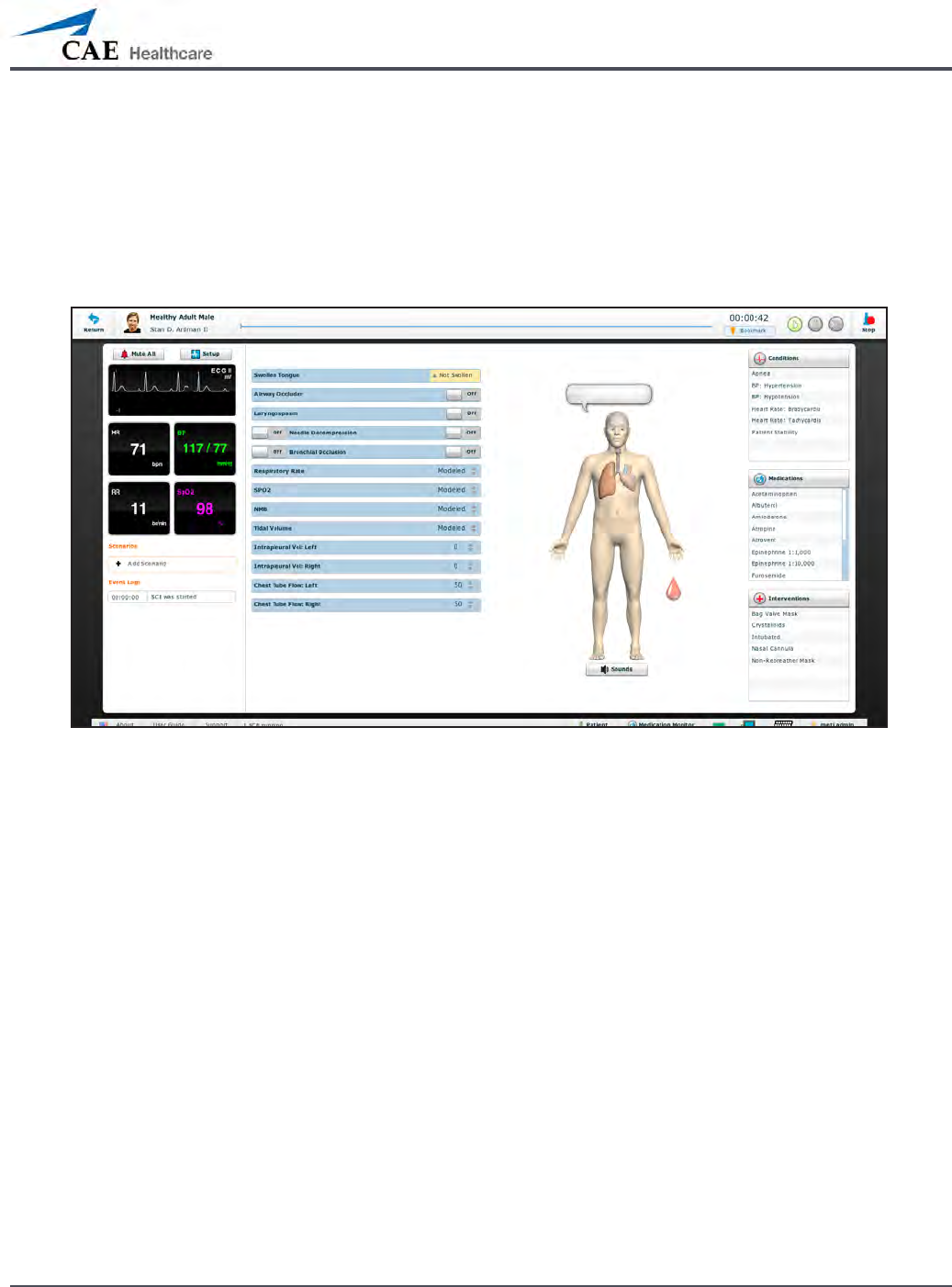
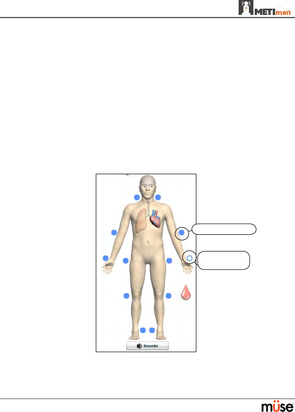
The Run Screen
126
Using METIman
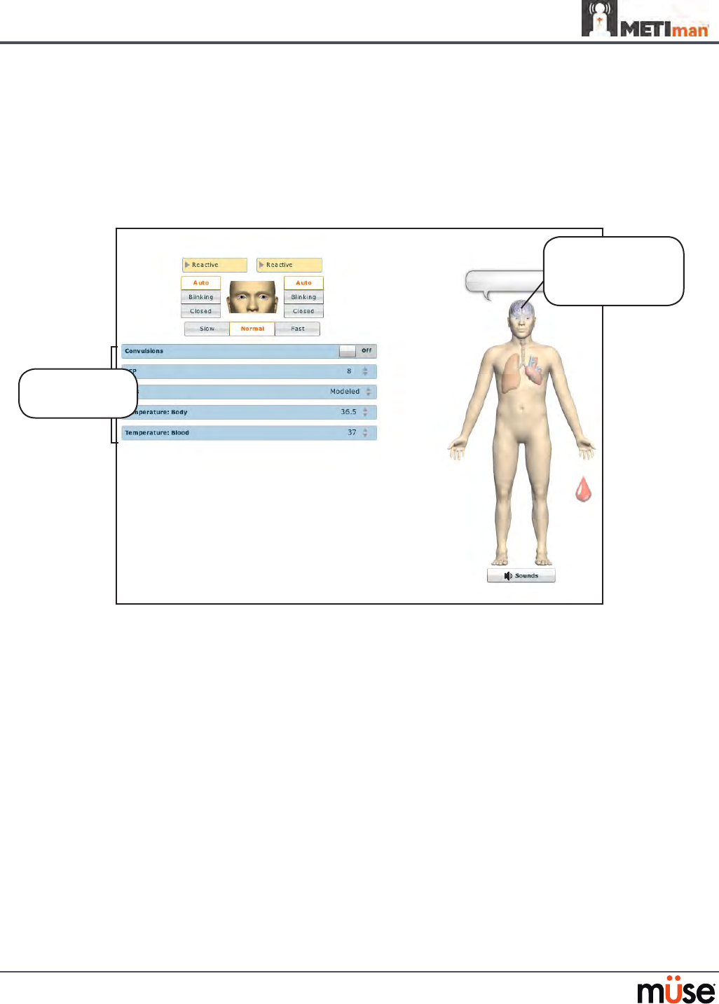
Neurological
The clinical features that can be controlled from the Neurological Assessment view
are Blinking Eyes, Reactive Pupils, Convulsions, Neuromuscular Block, Body and Blood
Temperature and Speech.
To access the Neurological view, from the Run screen, click the brain on the human form.
The Neurological View
Neurological
parameters
Click the brain
to access the
Neurological view

127
Using METIman
Eyes
The pupil diameter, pupil reactivity, blinking and blink speed of the simulator’s eyes can be
controlled from the software.
Click the Reactive drop-down menus of each eye to determine reactivity: Reactive, Non-
Reactive, Pinpoint or Blown.
Click Auto to have the eyes blink while the patient is conscious. Click Closed to close the eyes.
Click Blinking to force the eyes to be open and blinking regardless of patient consciousness.
These features can be controlled on both eyes.
Click Slow, Normal or Fast to control the blink speed.
Convulsions
METIman simulates convulsions when the feature is activated on the software. To activate
the Convulsions feature, click the Convulsions switch. The Convulsions feature is activated
when On appears. To deactivate the convulsions feature, click the switch again. The feature is
deactivated when O appears.
Neuromuscular Blockade
To manually adjust the Neuromuscular Blockade (NMB: Set), click NMB. The NMB slider
appears. Set the percentage by dragging the arrow up or down. Click Accept to exit and save
the changes.
Body Temperature
To control a patient’s body temperature, click Temperature: Body. The Body Temperature
slider appears. Set the body temperature by dragging the arrow up or down. Click Accept to
exit and save the changes.
Blood Temperature
To manually control a patient’s blood temperature, click Temperature: Blood. The Blood
Temperature slider appears. Set the temperature by dragging the arrow up or down. Click
Accept to exit and save the changes.
128
Using METIman
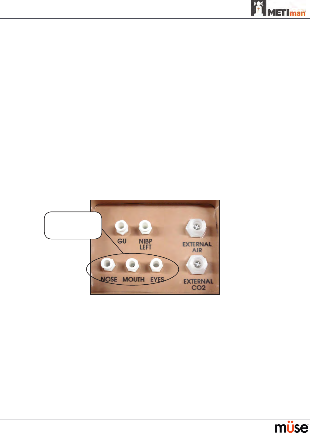
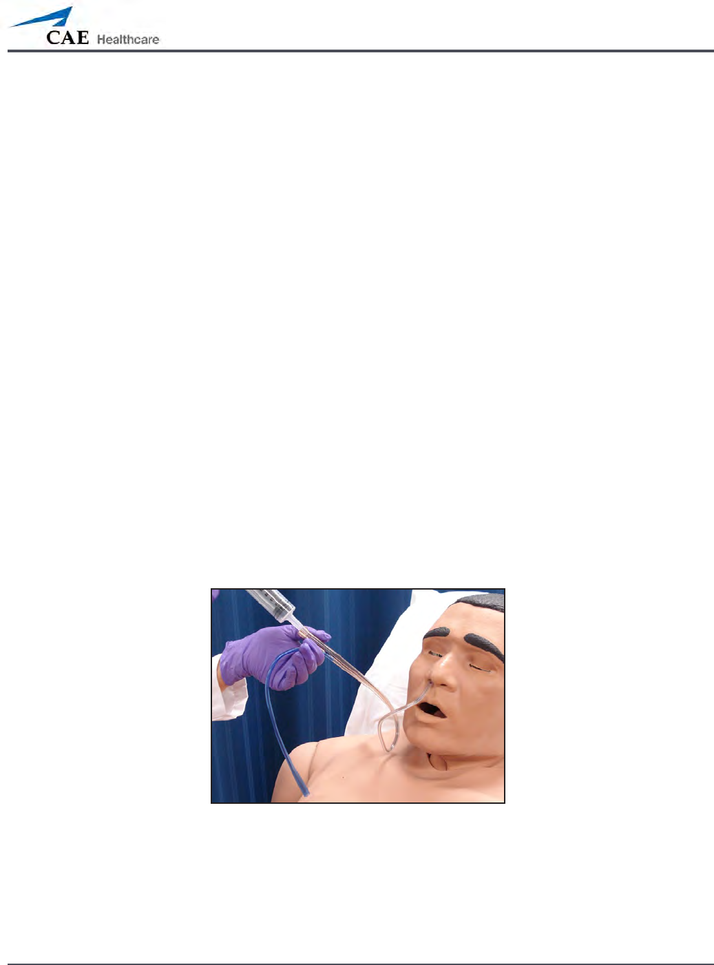
Head Secretions (Prehospital Only)
Secretions of the eyes, nose and mouth are manually controlled with a gravity feed.
NOTE: An IV bag is needed for each site in use.
To use the head secretion features:
Using a 60 mL syringe, prime the line of the desired secretion by injecting uid
1.
into the NOSE, MOUTH or EYES port on METIman’s left shoulder until uid
emerges from the secretion sites.
Set up the IV pole near the simulator.
2.
Fill an IV bag with the clinically appropriate uid. Use distilled water only, with 3.
food coloring, if desired.
Hang the IV bag on the IV pole.
4.
Ensure the roller clamp is closed and insert the IV spike into the IV bag.5.
Connect to the simulator by attaching the end of the IV spike set tubing to the 6.
NOSE, MOUTH or EYES port on the simulator’s left shoulder. (Repeat for each site
necessary.)
METIman Prehospital’s Left Shoulder
Open the clamp and allow uid to ow into the simulator. 7.
Keep the IV bag attached. Adjust the ow rate manually using the roller clamp.8.
NOTE: Cleanup is very important when using simulated uids. Please refer to the Care and
Maintenance section for directions on uid removal.
The NOSE,
MOUTH and
EYES ports
129
Using METIman
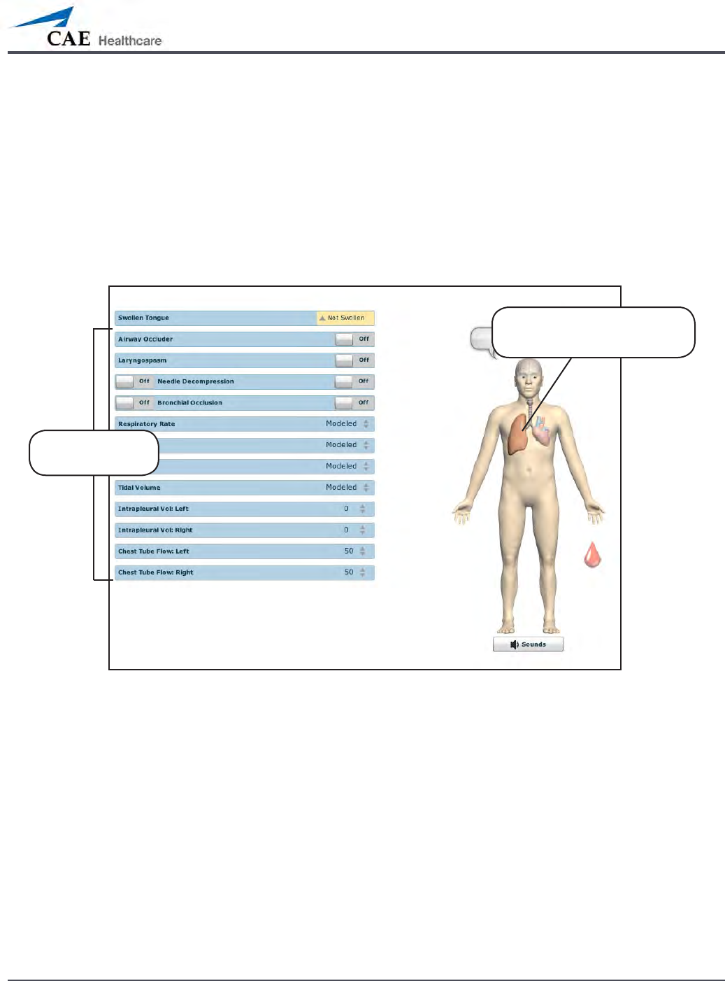
Respiratory
METIman Prehospital’s Respiratory system is comprised of the airway management,
spontaneous breathing and ventilation features. On METIman Nursing, various clinical signs
such as breath sounds, chest excursion and airway patency can be physically demonstrated.
A series of speakers inside each simulator can generate a range of breath and throat sounds
used in diagnosing conditions. To access the Respiratory parameters of METIman, on the
Run screen, click the lung on the human form. The respiratory parameters appear on the Run
screen.
The Respiratory View
Click the lung to access
the Respiratory view
Respiratory
parameters

130
Using METIman
Airway
Various clinical signs such as breath sounds, chest excursion and airway patency can be
physically demonstrated. A series of speakers inside the simulator can generate a range of
breath and throat sounds used in diagnosing conditions.
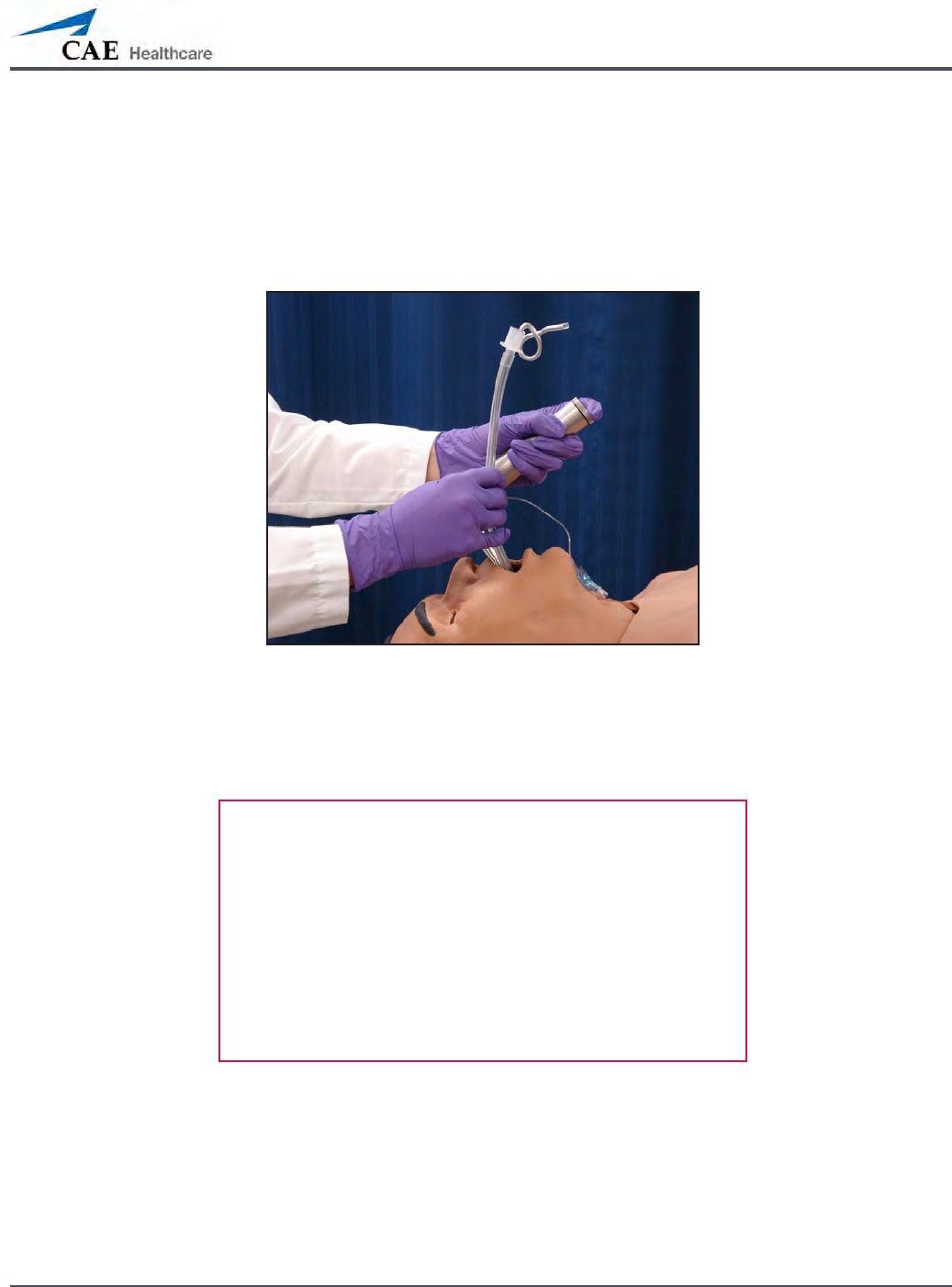
METIman Prehospital’s anatomically realistic upper airway provides for the opportunity to
intubate the patient as well as apply other airway interventions. In addition, the METIman
Prehospital airway was designed to be a dicult airway that teaches learners to use the
best technique when encountering clinical situations with real patients. The airway is best
visualized when using the Sellick maneuver, which is performed when a patient is undergoing
the intubation procedure.
The METIman Nursing airway has the ability to produce secretions to allow for suctioning.

131
Using METIman
Airway Features
Anatomy, Physiology
and Clinical Signs Clinical Interventions, Patient
Monitoring and Scenarios. Software Control Manual
Control
Realistic Upper
Airway (Oropharynx,
Nasopharynx and Larynx)
(Prehospital only)
Allows direct laryngoscopy, oral and
nasal intubation and use of specialty
airway devices. Simulator detects
and responds appropriately to right
mainstem intubation. Endobronchial
intubation results in unilateral chest
excursion and breath sounds.
None required. None required.
Trachea, Left and Right
Mainstem Bronchi
(Prehospital only)
Tracheal intubation results in bilateral
chest excursion and breath sounds. None required. None required.
Airway Management and
Ventilation
Alveolar and arterial gas concentrations
appropriately reect the ecacy of
ventilation and oxygen administration.
Oxygen
administration input
by the instructor.
VIEW: Respiratory
None required.
Gastric Distention
(Prehospital only)
Esophageal intubation results in gastric
distension and the absence of breath
sounds, chest excursion and CO2 output.
None required. None required.
Breakaway Teeth
(Prehospital only)
Upper front teeth can be dislodged if
laryngoscopy is performed incorrectly. None required. See Breakaway
Teeth
Tongue Edema
(On/O)
Hinders, but does not prevent,
intubation. VIEW: Respiratory None required.
Posterior Pharynx
Swelling
(Prehospital only)
Obstructs view of larynx to prevent
intubation, but allows mask ventilation
“can’t intubate, can ventilate” scenario.
VIEW: Respiratory None required.
Laryngospasm
(Prehospital only)
Closes vocal cords and prevents
intubation and ventilation. When used
with posterior pharynx swelling, creates
a “can’t intubate, can’t ventilate” scenario.
VIEW: Respiratory None required.
Cricothyroid Membrane Allows needle cricothyrotomy,
transtracheal jet ventilation, retrograde
wire techniques and cricothyrotomy.
None required. See
Cricothyrotomy,

132
Using METIman
Swollen Tongue
The swollen tongue feature is activated on the Respiratory view by setting the Swollen
Tongue switch to Swollen.
Posterior Pharynx Swelling (Prehospital Only)
Swelling of the posterior oropharynx (posterior airway occlusion) can be activated to obstruct
the view of the larynx and prevent intubation, but allow mask ventilation of the patient’s
lungs, thereby creating a “cannot intubate, can ventilate” scenario. Click the Airway Occluder
switch to activate the feature.
133
Using METIman
Realistic Upper Airway (Prehospital Only)
The upper airway of METIman Prehospital is designed to allow for intubation and
laryngoscopy. Oral and nasal intubation can be performed using a variety of airway devices,
including LMAs (3), endotracheal tubes (6.5 mm to 7.5 mm), nasal-pharyngeal airways (30 mm)
and oropharyngeal airways (90 mm).
Intubation
The simulator detects and responds appropriately to right mainstem intubation, and an event
is recorded in the Event Log.
Intubation incorrectly applied into the esophagus causes abdominal distension.
IMPORTANT
Airways can be damaged by improper insertion of an
airway adjunct (e.g. endotracheal tube). To protect the
airway, lubricate the adjunct prior to insertion using the
silicone spray provided.
Use ONLY the provided SILICONE SPRAY to lubricate the
adjunct. NEVER use a water-based lubricant because of
resulting residue damage.

134
Using METIman
Laryngospasm (Prehospital Only)
A laryngospasm actuator closes the patient’s vocal cords and prevents both ventilation and
intubation. Click the Laryngospasm switch to activate the feature.
Teeth with Breakaway Incisors (Prehospital Only)
METIman Prehospital is equipped with Breakaway Teeth whose front incisors become
dislodged with improper handling of a laryngoscope.
The teeth are tied to the upper denture with a lanyard, which prevents losing the teeth down
the airway or misplacing them during storage.
135
Using METIman
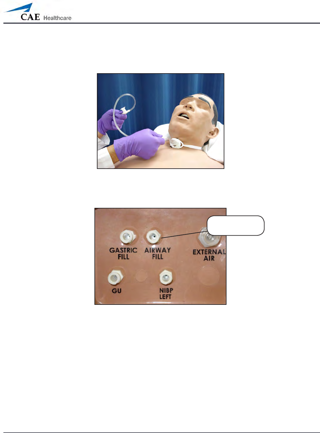
Airway Secretions (Nursing Only)
METIman Nursing allows for suctioning of uids from the airway using a manual feed. Ensure
all uids have been removed from previous uses before each new use to prevent overlling.
Tracheostomy Suction
To use the airway secretion feature, inject up to 40 mL of clinically appropriate colored uid
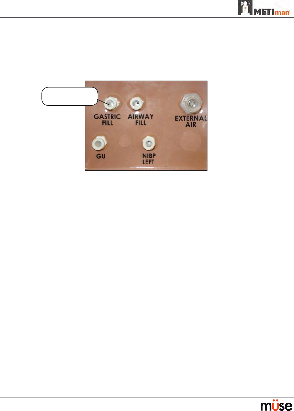
into the AIRWAY FILL port on METIman Nursing’s left shoulder.
METIman Nursing’s Left Shoulder
The trachea is now ready to be suctioned. Using the proper clinical technique, insert the
suction catheter (14 Fr) until resistance is encountered at the bifurcation. Withdraw and apply
suction. Fluid can be suctioned over a distance of approximately 4 cm distal to the bifurcation.
NOTE: Use only distilled water with food coloring, if desired.
NOTE: Cleanup is very important when using simulated uids. Please refer to the Care and
Maintenance section for directions on uid removal.
The AIRWAY
FILL port

136
Using METIman
Cricothyrotomy
Cricothyrotomy can be simulated on METIman. Before performing a needle cricothyrotomy,
the Cricothyrotomy plug must be removed, and a 2.25-inch (6-cm) length of red tape from the
roll provided must be placed over the hole.
To replicate a needle cricothyrotomy:
Spray the silicone lubricant onto the airway adjunct prior to the simulation
1.
session. To prevent damage to the simulator, always spray silicone lubricant into
the airway.
Locate the simulated cricothyroid membrane sealed with tape underneath the
2.
neck skin.
Follow standard clinical techniques and palpate to nd the cricothyroid space.
3.
Puncture the space through the neck skin of the patient simulator and into 4.
the tape “membrane.” This puncture goes all the way through to the “trachea,”
simulating the clinical procedure.
Users must replace the tape that simulates the cricothyroid membrane after each
5.
cricothyrotomy.
NOTE: Replacement components are available in the Inventory Kit.
NOTE: When ventilating through a surgical airway, the Laryngospasm feature must be
deactivated, or the chest rise is not observed.
NOTE: When nished using the Cricothyrotomy feature, replace the Crichothyrotomy plug.
Replacing the Cricothyrotomy Tape
Remove the old, punctured tape completely from the cricoid feature and use alcohol to clean
the glue residue from the surface. (An alcohol prep pad works well.) Allow to dry.
Cut an approximately 2.25-inch (6 cm) length of the double-sided tape from the roll provided.
Carefully remove the paper backing and lightly stretch the newly revealed adhesive side of the
tape over the cricoid hole and down the far side of the cricoid feature. Use the non-stick paper
backing to press the tape against the cricoid feature.
Cut a 2.5-inch to 3-inch (7 cm to 8 cm) length of red tape and apply it over the cricoid feature
and the tape.

137
Using METIman
Resealing the Membrane After a Puncture
To reseal the cricoid feature, apply a small piece of red tape over the punctured area. This
can be repeated a brief number of times, but when the number of layers impedes the
cricothyrotomy, all existing tape must be removed and replaced with new tape.

138
Using METIman
Pulmonary
METIman uses both physical and mathematical models to achieve an extremely accurate
simulation of respiration. METIman’s chest rises and falls, mimicking inspiration and expiration.
METIman Prehospital’s lungs also react realistically to intubation as well as to pathophysiologic
states.
Pulmonary System
Anatomy,
Physiology and
Clinical Signs
Clinical Interventions, Patient Monitoring
and Scenarios.
Software Control
Manual Control
Spontaneous
Breathing
Normal tidal breathing and pathophysiological
conditions such as atelectasis, pneumothorax,
asthma and COPD.
None required, but
adjustable
VIEW: Respiratory
None required.
Exhaled CO2
(Prehospital only)
Measure the presence or absence of CO2 during
positive pressure ventilation.
None required. CO2 canister is
inserted
Pneumothorax or
Hemothorax
Increase in intrapleural volume, leading to
asymmetrical breathing.
None required, but
adjustable
VIEW: Respiratory
CONTROL: Intrapleural
Volume
(Left or Right)
None required.
Chest Excursion Synchronized with ventilation (spontaneous or
positive pressure ventilation). Excursion depth
proportional to tidal volume.
None required. None required.
Breath Sounds Normal and abnormal breath sounds are
independently synchronized with ventilation of
the right and left lungs. Breath sounds can be
auscultated over anterior and posterior anatomic
locations.
None required, but
adjustable
VIEW: Sounds
None required.
Bronchial
Occlusion
Completely obstructs right and/or left mainstem
bronchi, simulating a lower airway obstruction
(e.g. mucus plug). This yields an inability to
ventilate the lungs and asymmetric chest
excursion.
VIEW: Respiratory None required.
Pulse Oximetry Oxyhemoglobin saturation (SpO2) automatically
correlates with the oxygen concentration in the
lungs and the intrapulmonary shunt fraction.
None required, but
adjustable
SpO2 probe is
attached.
Arterial Blood
Gases
PaO2, PaCO2 and pH are continuously calculated,
and the Patient Status Display can be congured
to show them.
None required, but
adjustable
None required.
Venous Blood
Gases
PvO2 and PvCO2 are continuously calculated, and
the Patient Status Display can be congured to
show them.
None required, but
adjustable
None required.
139
Using METIman
Pulmonary System
Needle
Decompression
(Prehospital Only)
Decompression of a pneumothorax can be
performed bilaterally by inserting a needle at the
midclavicular line of the second intercostal space.
The instructor must
adjust the amount
of physiologic
intrapleural air present.
VIEW: Respiratory
CONTROL: Needle
Decompression,
Intrapleural Vol: Left,
Intrapleural Vol: Right
See Needle
Decompression
setup,.
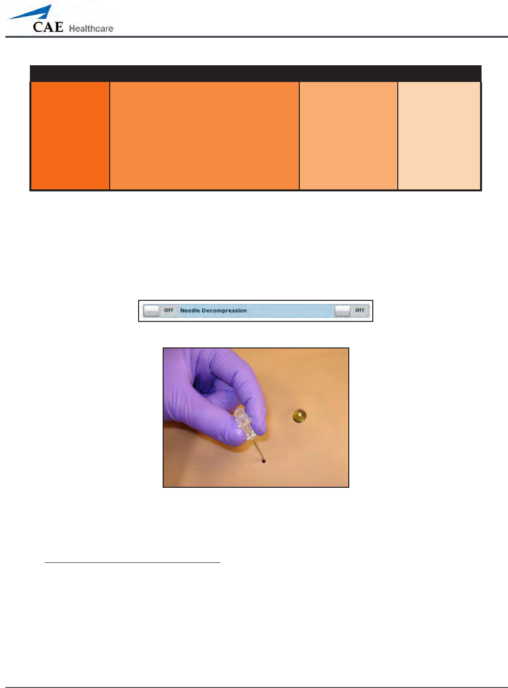
Needle Decompression (Prehospital Only)
Needle decompression can be performed bilaterally into a small hole located in the
midclavicular line of the second intercostal space using a 14-gauge needle.
To enable the Needle Decompression feature, activate the switch for the appropriate side(s).
From the Respiratory view, turn the desired Needle Decompression switch to On.
Needle Decompression Switch
Needle Decompression
When a needle is inserted in the second intercostal space, along the midclavicular line, air is
released while intrapleural volume is present.
Needle Decompression and Chest Tube
When using the METIman Prehospital system, the Needle Decompression and Chest Tube
features can be enabled simultaneously. Intrapleural volume will decrease when both are in
use.
140
Using METIman
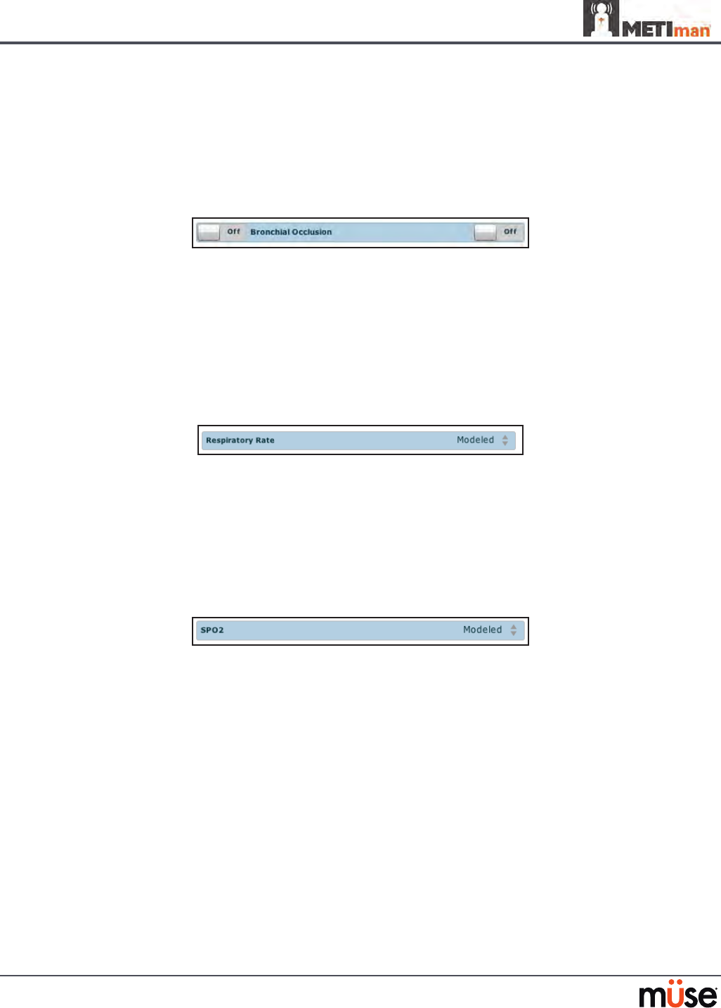
Bronchial Occlusion (Prehospital Only)
When bronchial occlusion is enabled, unilateral chest excursion is observed during
spontaneous breathing or positive pressure ventilation. To stop airow to the bronchi,
creating a bronchial occlusion, the switch for the appropriate side(s) must be activated. From
the Respiratory view, turn the desired Bronchial Occlusion switch to On.
Bronchial Occlusion Switch
Respiratory Rate
To adjust the respiratory rate manually, from the Respiratory view, click Respiratory Rate. The
Respiratory Rate slider appears. Set the rate by dragging the arrow up or down. Click Accept
to exit and save the changes. The switch is now orange, indicating a change has been made. To
return to the programmed physiologic model, click the switch and turn the Override switch to
Modeled.
Respiratory Rate Parameter
Pulse Oximetry
To adjust the SpO2 percentage manually, from the Respiratory view, click SpO2. The SpO2
slider appears. Set the rate by dragging the arrow up or down. Click Accept to exit and save
the changes. The switch is now orange, indicating a change has been made. To return to the
programmed physiologic model, click the switch and turn the Override switch to Modeled.
SPO2 Parameter
The SpO2 probe is integrated with the TouchPro (optional) and the physiological model. The
connection for the SpO2 probe is located on the left side of the simulator. The SpO2 probe must
be connected for pulse oximetry data to be displayed.
CO2 Exhalation (Prehospital Only)
Whether supplied via a portable canister or from an external source, the simulator exhales CO2
during positive pressure ventilation.
NOTE: An optional regulator kit must be purchased to use CO2 from an external source.
To use the CO2 Exhalation feature, connect the CO2 canister to the CO2 canister socket or
connect the external source on the simulator’s right shoulder, and METIman Prehospital
exhales CO2 gas. There are approximately 15 minutes of CO2 gas available once the canister is
connected.
141
Using METIman
Positive Pressure Ventilation
When positive pressure ventilation is administered, the process is automatically detected by the
simulator, and the physiologic model is sensitive to the volume administered.
Gastric Distention (Prehospital Only)
During esophageal intubation or overly aggressive bag valve mask ventilation, gastric distention
occurs. Gastric distention is relieved by putting pressure on the abdomen.
Chest Tube: METIman Prehospital
METIman Prehospital has the ability to simulate chest tube drainage. The Chest Tube sites are located
bilaterally in the fth intercostal space. Use only a 28 Fr chest tube. Ensure all uids have been removed
from previous uses before each new use to prevent overlling. Please refer to the Care and Maintenance
section for directions on uid removal.
To simulate continuous chest tube drainage:
Insert the METIman Priming Tube in the Chest Tube site.
1.
Set up the IV pole near the simulator.2.
Fill an IV bag with the clinically appropriate uid. Use distilled water only, with food 3.
coloring if desired.
Hang the IV bag on the IV pole.
4.
Ensure the roller clamp is closed and insert the IV spike into the IV bag.5.
Connect to the simulator by attaching the end of the IV spike set tubing to the 6.
corresponding CHEST TUBE port (LEFT or RIGHT) on the simulator’s right shoulder.
METIman’s Right Shoulder
Open the clamp and allow uid to ow into the simulator until uid is seen in the METIman 7.
Priming Tube.
Chest Tube ports
142
Using METIman
Once uid appears in the METIman Priming Tube, remove the METIman Priming 8.
Tube. The simulator is ready for chest tube insertion.
Keep the IV bag attached and adjust the ow rate manually using the roller clamp.
9.
The chest tube must be fully inserted for the uid to ow.
Chest Tube Insertion
NOTE: Cleanup is very important when using simulated uids. Please refer to the Care and
Maintenance section for directions on uid removal.
When the Chest Tube feature is used on METIman Prehospital, the simulator automatically
detects the tube insertion and creates a log entry.
On METIman Prehospital, if a small volume of uid is needed to simulate proper chest tube
insertion, the internal reservoir may be lled.
To insert a small amount of uid into the Chest Tube reservoir:
Insert the METIman Priming Tube in the Chest Tube site.
1.
Using a 60 mL syringe lled with clinically appropriate uids, inject the contents 2.
into the CHEST TUBE port (LEFT or RIGHT) until uid is seen in the METIman
Priming Tube. Use distilled water only, with food coloring, if desired.
Remove the METIman Priming Tube.
3.
Inject the remaining contents of the syringe into the 4. CHEST TUBE port.
Remove the syringe.
5.
Chest Tube and Needle Decompression
The Chest Tube and Needle Decompression features can be enabled at the same time on the
METIman Prehospital system. Intrapleural volume will decrease when both are in use.
143
Using METIman
Chest Tube: METIman Nursing
METIman Nursing has the ability to simulate chest tube drainage. The Chest Tube sites are
located bilaterally in the fth intercostal space. Use only a 28 Fr chest tube. Ensure all uids
have been removed from previous uses before each new use to prevent overlling. Please refer
to the Care and Maintenance section for directions on uid removal.
To simulate continuous chest tube drainage:
Insert the METIman Priming Tube in the Chest Tube site.
1.
Set up the IV pole near the simulator.2.
Fill an IV bag with the clinically appropriate uid. Use distilled water only, with 3.
food coloring if desired.
Hang the IV bag on the IV pole.
4.
Ensure the roller clamp is closed and insert the IV spike into the IV bag.5.
Connect to the simulator by attaching the end of the IV spike set tubing to 6.
the corresponding CHEST TUBE port (LEFT or RIGHT) on the simulator’s right
shoulder.
METIman’s Right Shoulder
Open the clamp and allow uid to ow into the simulator until uid is seen in the 7.
METIman Priming Tube.
Once uid appears in the METIman Priming Tube, remove the METIman Priming
8.
Tube. The simulator is ready for chest tube insertion.
Keep the IV bag attached and adjust the ow rate manually using the roller clamp.
9.
The chest tube must be fully inserted for the uid to ow.
NOTE: Cleanup is very important when using simulated uids. Please refer to the Care and
Maintenance section for directions on uid removal.
Chest Tube ports

144
Using METIman
Cardiovascular
With METIman’s Cardiovascular system, users can replicate the clinical signs associated with
cardiac activity, including palpable pulses, heart sounds and electrical activity.
Cardiovascular System
Anatomy,
Physiology and
Clinical Signs
Clinical Interventions, Patient Monitoring
and Scenarios.
Software Control
Manual
Control
Heart Sounds Normal and abnormal heart sounds are
synchronized to the cardiac cycle and audible
to a standard stethoscope. Heart sounds can be
auscultated over the left and right upper sternal
border, right lower sternal border and apex.
None required;
specic sounds can be
selected.
VIEW:
Cardiovascular
None required.
5-Lead ECG ECG waveforms can be viewed on a standard
monitor and/or on the TouchPro Patient monitor.
Normal and abnormal cardiac rhythms are
linked to patient physiology (e.g. blood pressure,
cardiac output).
None required;
specic rhythms can
be selected.
ECG monitor may
be utilized.
Myocardial
Ischemia
Myocardial oxygen supply and demand
automatically inuence the cardiac rhythm,
yielding response to hypoxemia.
None required, but
adjustable.
None required.
Palpable Pulses Carotid, brachial, radial, femoral, popliteal,
posterior tibial and dorsalis pedis pulses can be
palpated bilaterally and are synchronous with
the cardiac cycle. A pulse decit automatically
occurs if the systolic arterial blood pressure falls
below specied thresholds.
None required, but
adjustable.
VIEW:
Available on
all views on the Run
screen
None required.
Non-Invasive
Blood Pressure
Measurement
Systemic blood pressure can be measured using
the return-to-ow technique. Korotko sounds
can also be auscultated.
None required. Use of modied
blood pressure
cu.
145
Using METIman
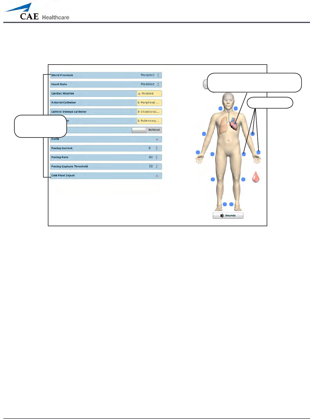
To access the Cardiovascular parameters of METIman, on the Run screen, click the heart on the
human form. The cardiovascular features appear on the Run screen.
The Cardiovascular View (Prehospital)
Click the heart to access the
Cardiovascular view
Pulses
Cardiovascular
parameters
146
Using METIman
Pulses: METIman Prehospital
METIman Prehospital has 14 pulse sites that are activated by touch.
Carotid (2)•
Brachial (2)•
Radial (2)•
Femoral (2)•
Popliteal (2)•
Posterior Tibial (2)•
Dorsalis Pedis (2)•
NOTE: The Dorsalis Pedis and Posterior Tibial pulses are controlled together. The left and right
Carotid pulses are also controlled together.
Pulses are visible and can be controlled from any physiological view. To disable a pulse, click
the pulse location on the human form. To enable a pulse, click the pulse location again.
Pulses: METIman Prehospital – Active and Inactive
Activated pulse
Deactivated
pulse
147
Using METIman
Pulses: METIman Nursing
METIman Nursing has 14 pulse sites that are activated by touch.
Carotid (2)•
Brachial (2)•
Radial (2)•
Femoral (2)•
Popliteal (2)•
Posterior Tibial (2)•
Dorsalis Pedis (2)•
NOTE: The left and right Carotid pulses are controlled together.
Pulses are controlled from the Cardiovascular view only. All pulses, unless altered by an SCE,
are enabled by default. To disable a pulse, click the pulse location on the human form. To
enable a pulse, click the pulse location again.
Pulses: METIman Nursing – Active and Inactive
Activated pulse
Deactivated
pulse

148
Using METIman
Blood Pressure
METIman supports non-invasive blood pressure measurements, and systolic and diastolic
readings can be obtained and manipulated through the software.
Systolic and Diastolic Blood Pressure
To manually adjust the systolic and/or diastolic blood pressure:
From the Cardiovascular view, click the parameter of desired blood pressure.
1.
Set the pressure by dragging the arrow up or down. 2.
Click 3. Accept to exit and save the changes. The switch is now orange, indicating a
change has been made.
To return to the programmed physiologic model, click the switch and turn the
4.
Override switch to Modeled.
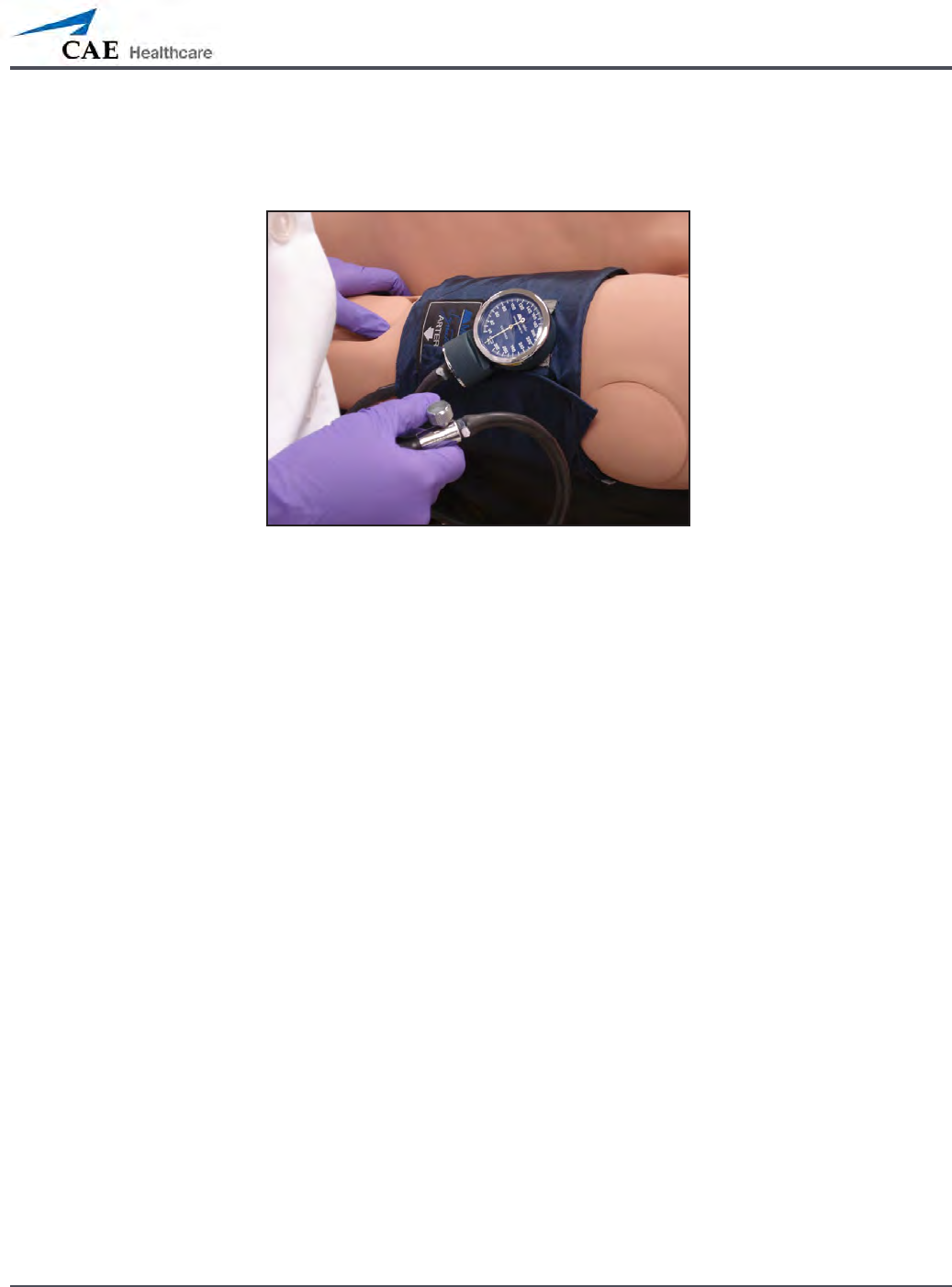
Non-Invasive Blood Pressure Measurement
Blood pressure can be taken manually on either arm. Non-invasive blood pressure (NIBP)
monitoring techniques can be used by attaching the standard cu modied with a T-tting
and adapters.
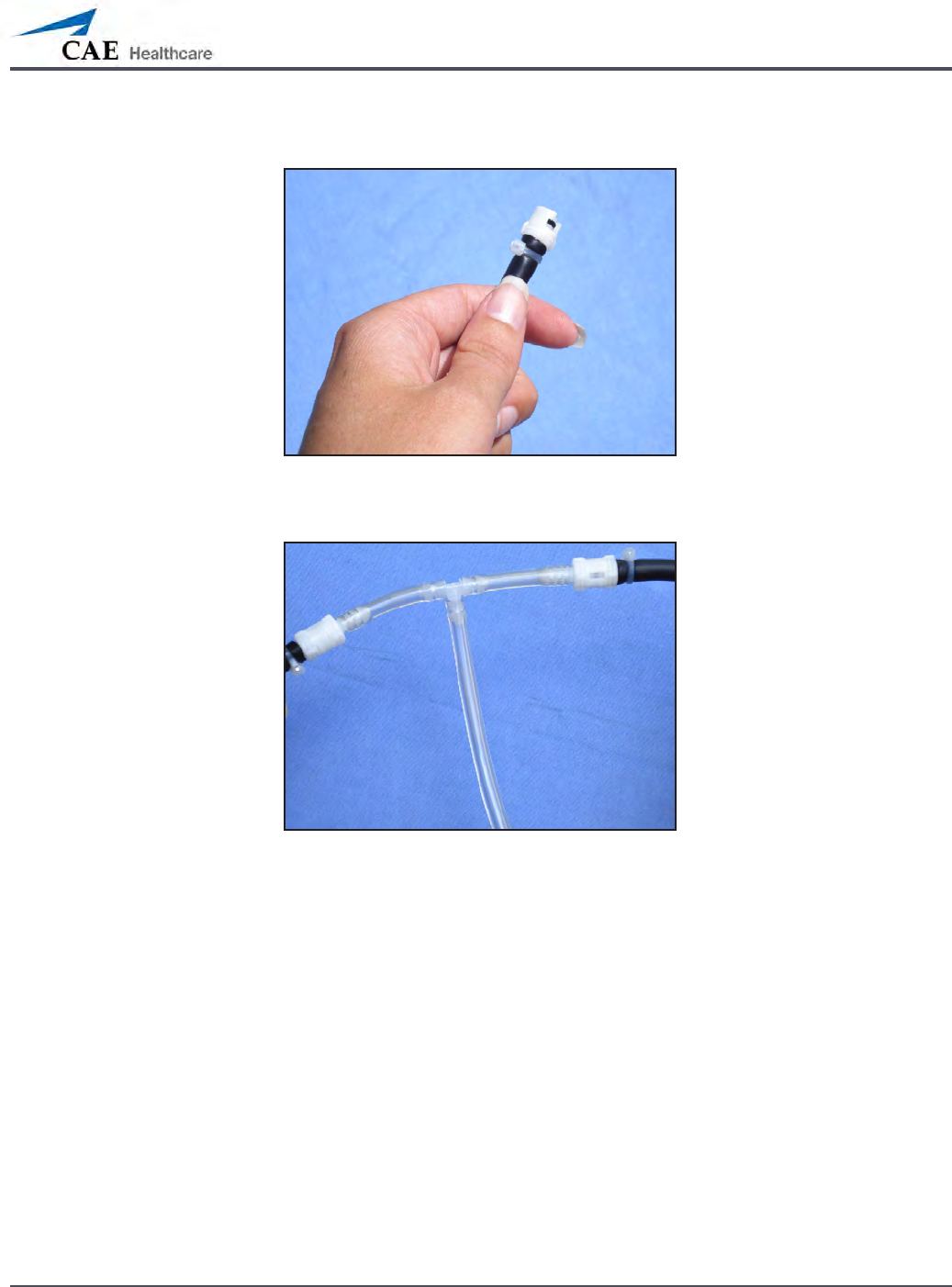
To modify a standard blood pressure cu:
Cut the blood pressure cu tube approximately 9 cm from the cu.
1.
Insert the barbed end tubing connectors into the cut ends of the blood pressure 2.
cu tubes.
149
Using METIman
Secure the tubing connectors with cable ties. 3.
An Attached Tubing Connector
Attach the blood pressure adapter to the connectors.4.
An Attached Blood Pressure Cu Adapter
150
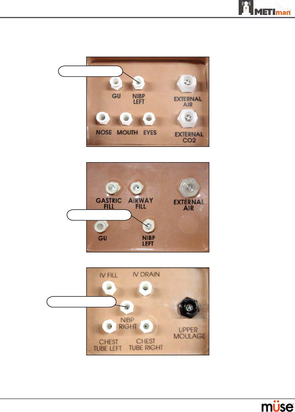
Using METIman
To get a blood pressure reading, connect the extension from the T-tting on the blood
pressure cu adapter to either of the NIBP ports on METIman’s left and right shoulders.
METIman Prehospital’s Left Shoulder
METIman Nursing’s Left Shoulder
METIman’s Right Shoulder
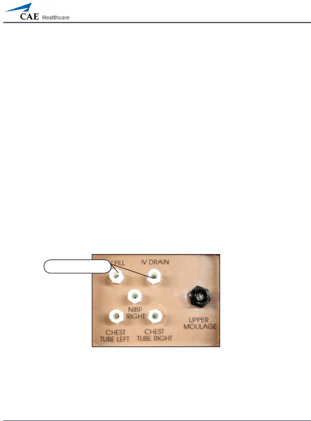
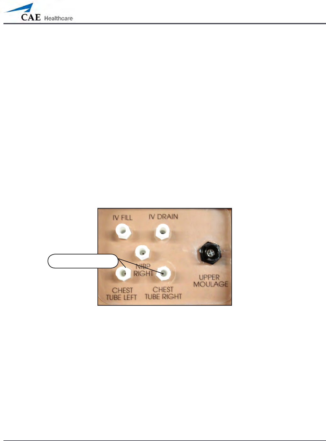
NIBP RIGHT port
NIBP LEFT port
NIBP LEFT port
151
Using METIman
Connect the T-tting extension to the hose.
Take the non-invasive blood pressure reading using the return-to-ow technique.
Attached Blood Pressure Cu
At appropriate cu pressures, Korotko sounds are produced, and the radial pulse disappears.
152
Using METIman
Heart Rate
To manually adjust the heart rate, from the Cardiovascular view, click Heart Rate. Set the rate
by dragging the arrow up or down.
Click Accept to exit and save the changes. The switch is now orange, indicating a change has
been made.
To return to the programmed physiologic model, click the switch and turn the Override switch
to Modeled.
Five-Lead ECG
On METIman, a 5-lead ECG is emitted from the appropriate positions for display on a standard
monitor. A contact is available on METIman’s chest for each of the ve cables.
5-Lead ECG Sites
The simulator generates a normal sinus ECG, as well as a broad range of abnormalities such as
myocardial ischemia, sinus tachycardia and bradycardia, ventricular brillation and asystole.
The hemodynamic response to the arrhythmias is physiologically correct. Myocardial oxygen
balance and cardiac ischemia automatically inuence the cardiac rhythm resulting in a
realistic and automatic response of the rhythm to hypoxemia. The degree of inuence can be
controlled or completely overridden by the instructor.
Five-Lead
ECG sites

153
Using METIman
Cardiovascular Interventions/Therapy
METIman can simulate chest compressions and three types of electrical therapy: debrillation,
cardioversion and pacing.
Realistic Cardiovascular Interventions
Anatomy,
Physiology and
Clinical Signs
Clinical Interventions, Patient
Monitoring and Scenarios.
Software Control
Manual
Control
Chest
Compression
Eective chest compression results in articial
circulation, cardiac output, central and
peripheral blood pressures, palpable pulses, and
CO2 return.
None required, but
adjustable.
None required.
Cardiac
Monitoring
The desired arrhythmia can be selected. The response to
clinical intervention
must be controlled by
the instructor.
VIEW:
Cardiovascular
None required.
Debrillation METIman supports operation with a variety of
manual and automatic external debrillators.
Debrillation can
be simulated by the
instructor under the
Interventions palette
VIEW:
Cardiovascular
See Debrillation
below for
debrillation disk
locations and
instructions.
Cardiac Pacing Transthoracic cardiac pacemaker can be used
with METIman. Pacing results in appropriate
physiological changes in blood pressure and
cardiac output.
None required. See Pacing below
for cardiac pacing
disk locations and
instructions.
154
Using METIman
Chest Compressions
METIman supports normal hand placement and standard compression techniques, and chest
compressions can be performed. METIman can detect the compressions, and the physiology
responds accordingly.
Debrillation and Cardioversion
Manual debrillation and cardioversion can be performed on METIman. Additionally,
debrillation and cardioversion are available virtually through the software.
METIman is designed to safely absorb the energy discharged from manual and automatic
debrillators. Standard debrillation energy levels should be used for positive learning
reinforcement and to avoid negative training transfer.
Debrillation Sites
However, use of a debrillator for training purposes represents an operational hazard
equivalent to use of a debrillator on a real patient. Consequently, ALL SAFETY PRECAUTIONS
for the use of debrillators MUST BE FOLLOWED as if the simulator were a patient. Consult the
specic debrillator’s user manual for further information.
Debrillation sites

155
Using METIman
The following cautions should be observed:
Defibrillation should be performed on the defibrillation electrodes only. If defibrillation •
is performed over any ECG electrode, high voltage may be present on the remaining
connectors during the shock. This may also damage ECG circuitry.
To prevent overheating, do NOT provide more than three (3) defibrillator discharges •
(maximum 200 joules with a biphasic defibrillator) in a sequence. Do NOT exceed an
average of two (2) defibrillator discharges per minute during the training session.
Avoid a large number of consecutive discharges. For example, 20 or 25 discharges •
without any recovery interval may damage the system.
Do NOT let the simulator come in contact with electrically conductive surfaces or •
objects during defibrillation. A flame-supporting atmosphere, for example, with a high
content of oxygen, should be avoided during defibrillation.
Keep the simulator’s chest dry. Special attention should be taken when using the urinary •
system or the chest tube feature.
To prevent pitting of the chest skin electrode, do NOT apply conductive gel or •
conductive defibrillation pads intended for patient use.
Do NOT use cables or connectors having visible damage.•
Do NOT spill fluids over any component inside the simulator torso. This could damage •
the system and may also present a possible hazard for the operator.
When using a manual defibrillator, the ECG can be monitored via the defibrillator •
paddles. Coarse ventricular fibrillation and high-rate ventricular tachycardia cardiac
rhythms are automatically recognized as “shockable” rhythms.
With each defibrillation, the METIman automatically records the amount of energy •
discharged and the time defibrillation was performed. The simulated patient response
to defibrillation is determined by the scenario script or instructor intervention. Thus,
cardioversion is not automatically determined by the physiological models.
The minimum electrical charge recognized by the circuitry within the simulator is 20 •
joules.
For paddle placement on the chest, the simulator has two anterior defibrillation disks, •
which can be unscrewed, leaving threaded connections, if required.
Biphasic defibrillators can be used with either paddles or hands-free connectors.•
Pacing
Pacing can be achieved virtually by selecting the appropriate intervention in the Interventions
palette. A standard transthoracic cardiac pacemaker can be connected to the simulator using
the anterior contacts. The simulator automatically detects and responds to pacing signals (from
20 mA to 200 mA, in increments of 10).
156
Using METIman
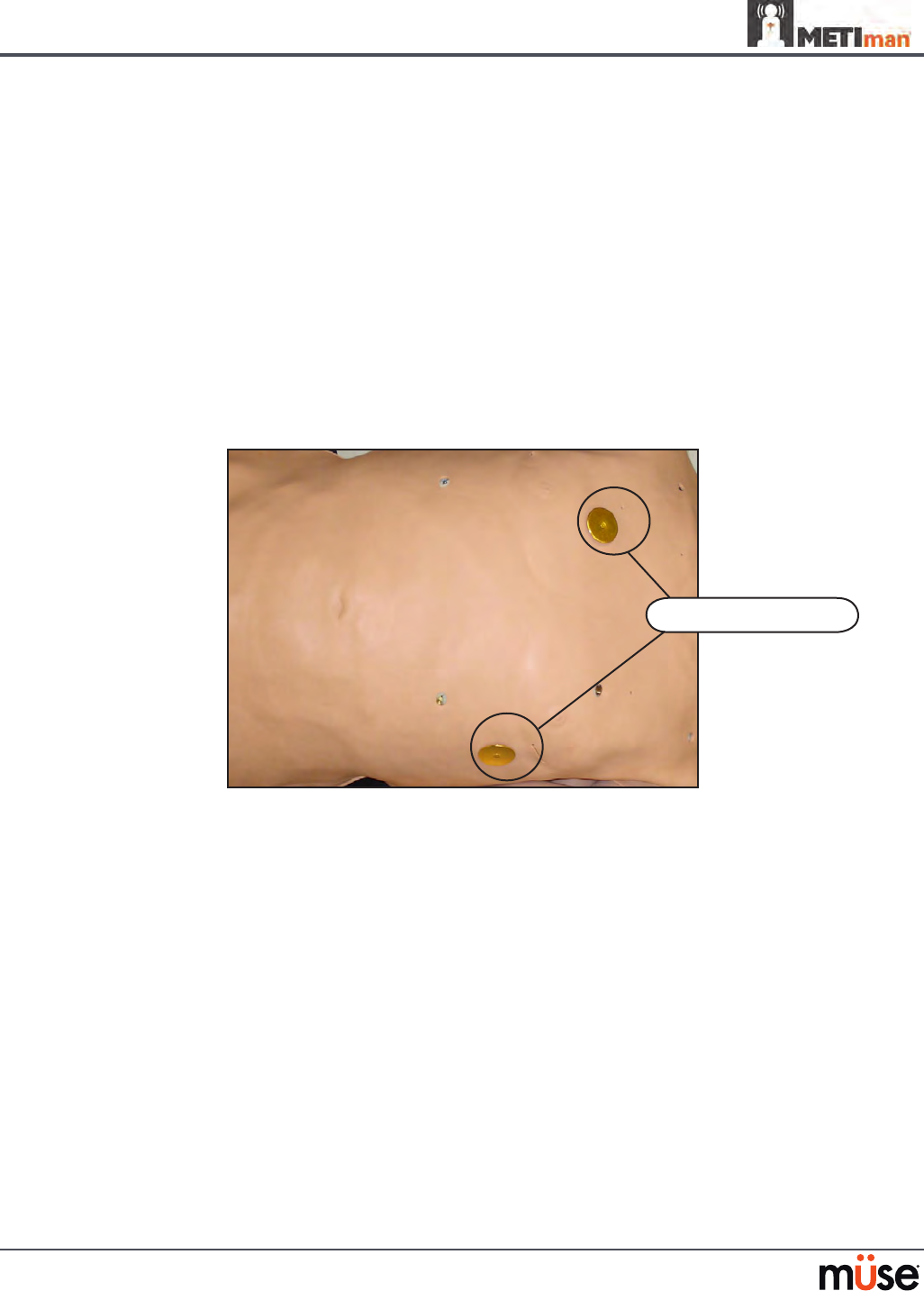
Subclavian Catheter (Nursing Only)
The Subclavian Catheter feature allows for cleaning and dressing practice. When using the
Subclavian Catheter feature, users can infuse up to 50 mL of distilled water in the line.
Subclavian Catheter
NOTE: Cleanup is very important when using simulated uids. Please refer to the Care and
Maintenance section for directions on uid removal.
Intramuscular Injection
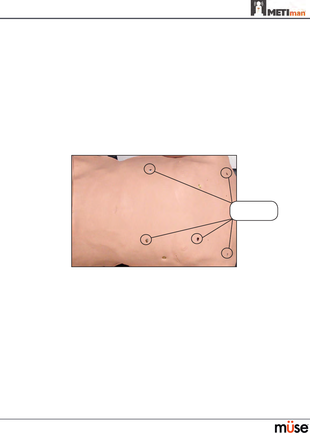
METIman allows for the administration of a deltoid intramuscular (IM) injection. Injection sites
are located on both of METiman’s arms. Use only a 20- to 22-gauge needle.
Intramuscular Injection
157
Using METIman
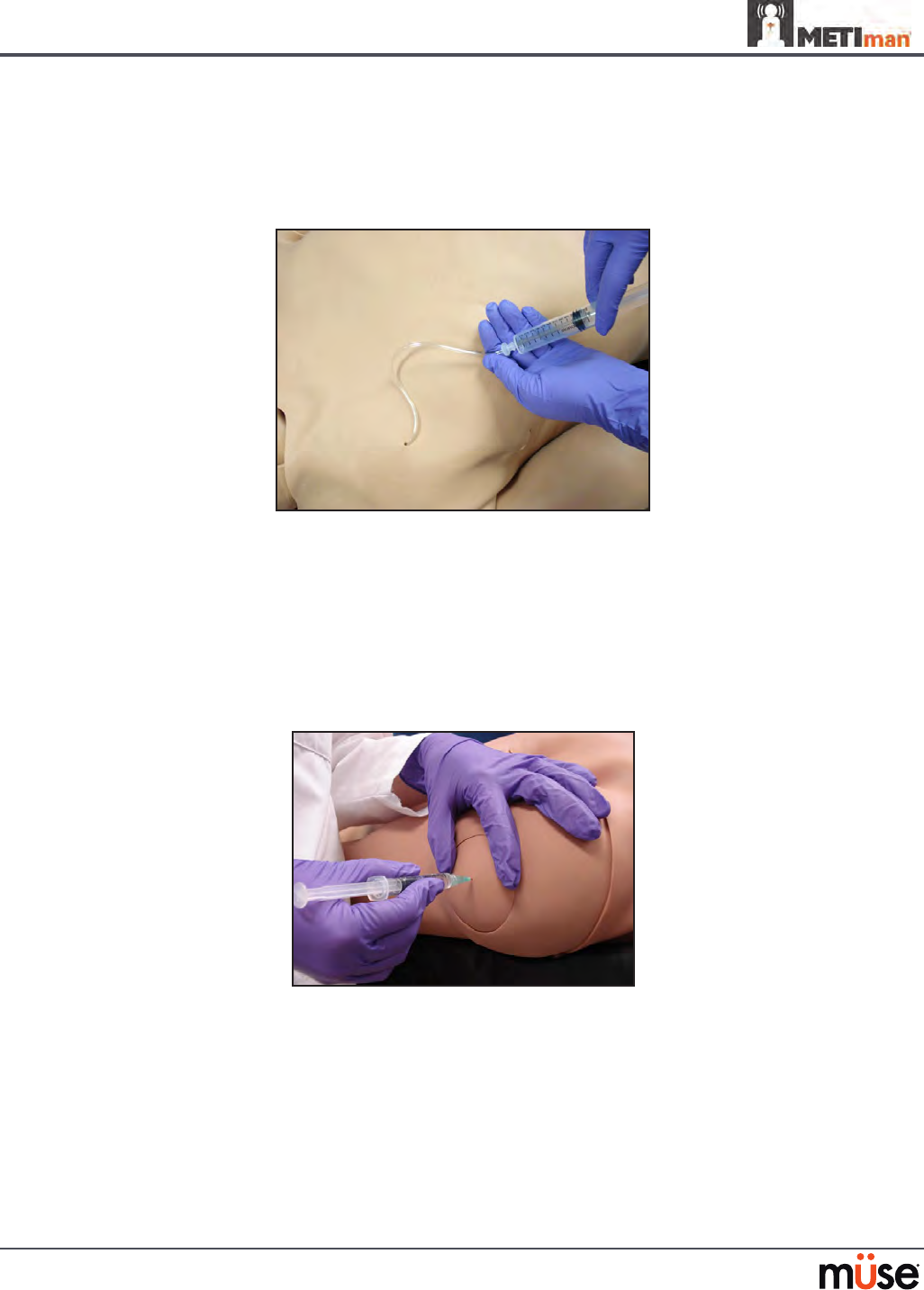
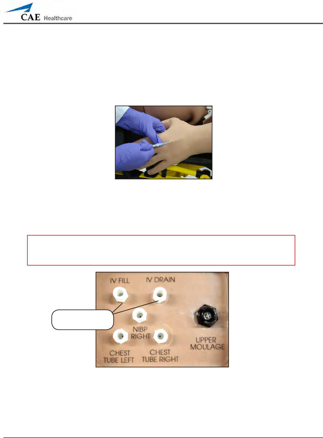
IV Cannulation
Veins for the IV Cannulation feature are located in the dorsum of the hands, forearms and
antecubital region of the arms. Use only a 20- to 22-gauge needle. To simulate realistic
ashback, the system must be primed prior to use. Ensure all uids have been removed
from previous uses before each new use to prevent overlling. Please refer to the Care and
Maintenance section for directions on uid removal.
IV Cannulation
To prime the IV access ports, connect a 60 mL syringe lled with distilled water (with clinically
appropriate food coloring if desired) to the IV FILL port on METIman’s right shoulder and rmly
inject all 60 mL. This primes the arms and charges the system for Flashback and Venipuncture
support.
WARNING: If a ash does NOT occur, do NOT inject any uid and remove the needle
immediately. Repeat the priming directions and ensure you have injected the needle
properly and into the simulated vein.
METIman’s Right Shoulder
Fluids and medications can be administered intravenously. Approximately 50 mL of uid may
be infused. To support infusion of larger volumes, connect an empty IV bag or other receptacle
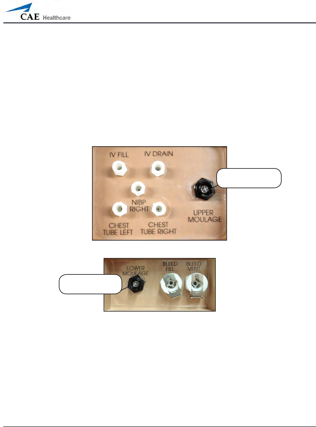
to the IV DRAIN port located on METIman right shoulder.
NOTE: Cleanup is very important when using simulated uids. Please refer to the Care and
Maintenance section for directions on uid removal.
IV FILL and IV
DRAIN ports
158
Using METIman
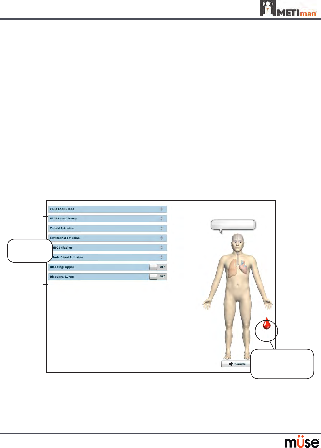
Fluids
METIman is capable of bleeding simultaneously at two sites from an internal tank. Arterial and
venous bleeding can be simulated.
Venous settings produce a continuous bleed at three user-adjustable ow rates.
Arterial settings produce a pulsing ow synchronized with the cardiac cycle at three user-
adjustable ow rates.
The ow rate is determined by the selected bleeding vessel size and the blood pressure.
In addition, the simulator features auto-sensing of hemorrhage control (e.g., tourniquet
application or direct pressure).
Bleeding results in an automatic loss of blood from the physiologic models with subsequent
changes in hemodynamics. Blood loss occurs at a rate dependent on wound size and Mean
Arterial Pressure (MAP).
Setup must be completed before using the bleeding feature.
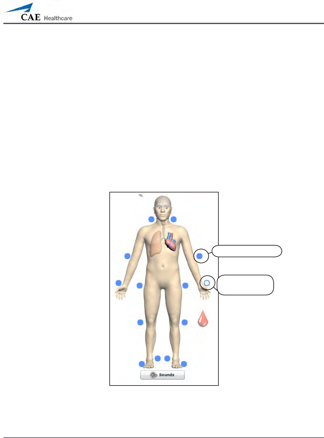
To enable bleeding, on the Run screen, click the blood droplet. The Fluids view appears.
The Fluids View
Simulated blood MUST be removed from the simulator after each use. Failure to remove
simulated blood from the simulator can void the warranty. For instructions on how to clean the
simulator after using the Bleeding feature, please refer to the Care and Maintenance section for
directions on uid removal.
Click the blood
droplet to access
the Bleeding view
Bleeding
parameters
159
Using METIman
Hemorrhage Setup
The user determines the type and placement of the bleeding moulage for the lesson. An
optional Moulage Kit can provide molded gunshot wounds, broken and protruding bones,
amputations and an abdominal wound as well as theatrical components.
To decrease the likelihood of staining, apply a thin coat of petroleum to the area of bleeding.
To use one of the moulage wounds from the Moulage Kit:
Secure the wound over the simulator using the integrated straps.
1.
Connect the wound haptic to the one of the moulage ports located on METIman’s 2.
right shoulder (UPPER MOULAGE) or right hip (LOWER MOULAGE).
METIman’s Right Shoulder
METIman’s Right Hip
Enable 3. Bleeding: Upper or Bleeding: Lower on the Fluids view of the Müse
software, as desired.
Hemorrhage Control
When bleeding is controlled (e.g., hemostat, tourniquet), the action is detected and logged,
and the physiology responds accordingly.
UPPER
MOULAGE port
LOWER
MOULAGE port
160
Using METIman
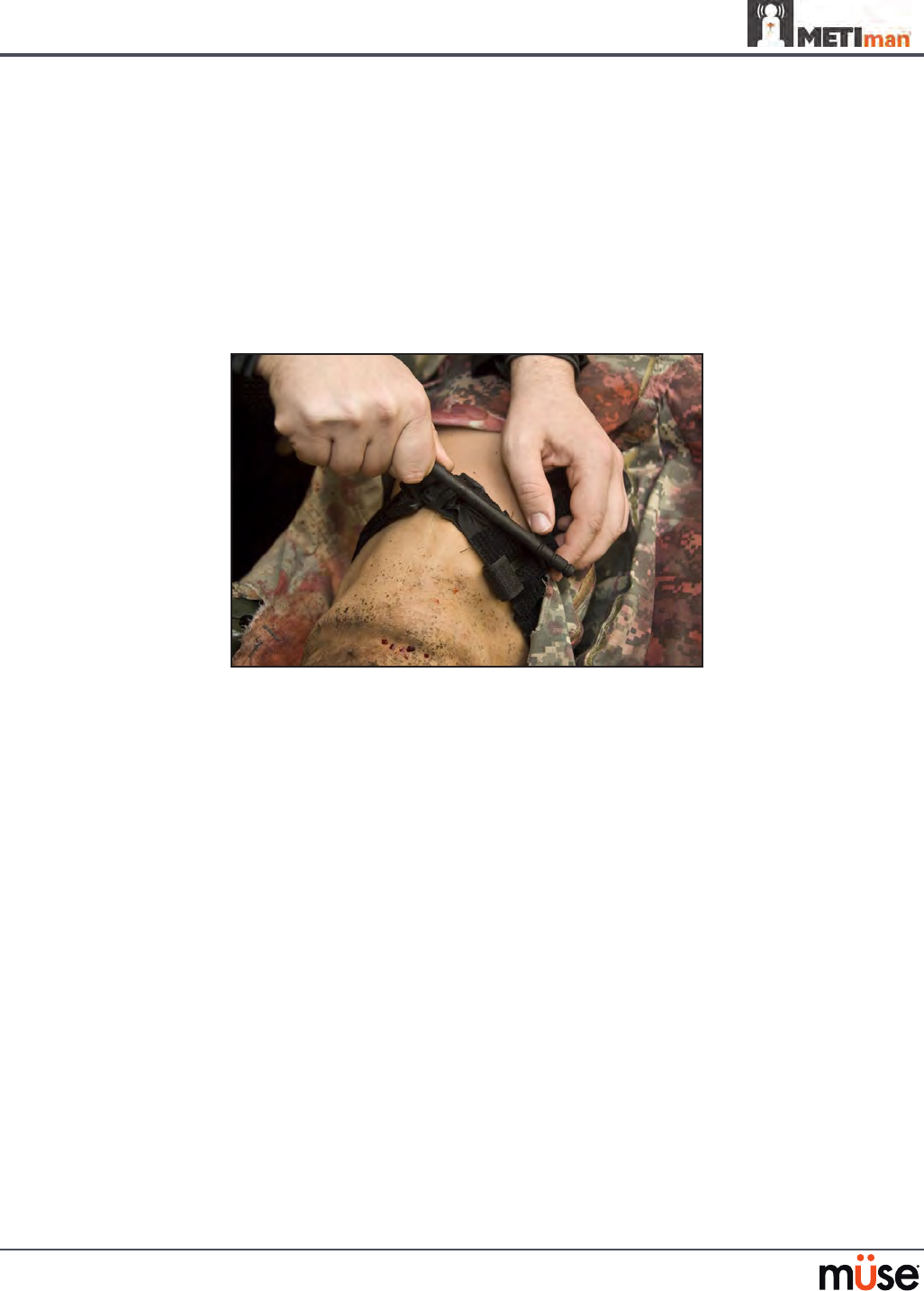
Tourniquet Application
A tourniquet may be applied to stop the ow of blood.
The wound umbilical contains an 18-inch section of soft tubing that allows the use of a
tourniquet to stop the ow of blood.
For added realism, the simulator should be dressed in clothing that can be torn to “conform”
with the type of injury being demonstrated. Bleeding moulages and the wound umbilical
should be concealed under the victim’s clothing with only the wound showing.
Tourniquet Application
Fluid Loss Blood
To manually control a patient’s blood loss, from the Fluids view, click the Fluid Loss Blood
parameter. The Fluid Loss Blood slider appears. Set the amount of blood loss by dragging the
arrow up or down. Click Accept to exit and save the changes.
Fluid Loss Plasma
To manually control a patient’s plasma loss, from the Fluids view, click the Fluid Loss Plasma
parameter. The Fluid Loss Plasma slider appears. Set the amount of Plasma loss by dragging the
arrow up or down. Click Accept to exit and save the changes.
161
Using METIman
Gastrointestinal
METIman produces realistic bowel sounds. In addition, on METIman Nursing, gastric lavage,
gavage and suction can be administered.
Gastrointestinal Gavage, Lavage and Suction (Nursing Only)
METIman Nursing has a gastric reservoir that allows for simulated gavage, lavage and gastric
suction. Before each use, ensure the reservoir has been drained completely. The reservoir
should be primed with 60 mL of uid before performing gastric suction (see Gastric Suction on
page 162 for more information). A maximum of 100 mL of uid may be added to the gastric
reservoir once the reservoir is primed.
Gavage (Nursing Only)
To perform gastrointestinal gavage, ensure the reservoir is empty and infuse uid according to
procedure using a 14 Fr nasogastric tube.
NOTE: Cleanup is very important when using simulated uids. Please refer to the Care and
Maintenance section for directions on uid removal.
NOTE: Ice the nasogastric tube if extra rigidity is needed for insertion.
Lavage (Nursing Only)
To perform gastrointestinal lavage, ensure the reservoir is empty and infuse uid normally
using a 14 Fr nasogastric tube. Fluids can then be removed according to proper clinical
procedure.
Gastric Lavage
NOTE: Cleanup is very important when using simulated uids. Please refer to the Care and
Maintenance section for directions on uid removal.
NOTE: Ice the nasogastric tube if extra rigidity is needed for insertion.
162
Using METIman
Gastric Suction (Nursing Only)
To perform gastric suction, the reservoir must be primed prior to use. To prime the
gastrointestinal reservoir, attach a syringe with a luer-lock extension set (provided) and inject
60 mL of distilled water into the GASTRIC FILL port on the simulator’s left shoulder.
METIman Nursing’s Left Shoulder
Fluids can then be removed according to procedure using a 14 Fr nasogastric tube.
NOTE: Cleanup is very important when using simulated uids. Please refer to the Care and
Maintenance section for directions on uid removal.
The GASTRIC
FILL port

163
Using METIman
Genitourinary System
METIman may be congured with either male or female genitalia, either of which allows for
the insertion of a urinary catheter. The genitourinary system also provides for the excretion of
urine.
Urinary Catheterization
Catheterize the simulator using a standard 16-Fr urinary catheter lubricated with silicone spray.
Urinary Catheterization
The bladder for the simulated urine is accessed directly via the urethra.
164
Using METIman
Simulating Urine Output
METIman allows urinary catheterization and simulation of urinary output. Ensure all uids have
been removed from previous uses before each new use to prevent overlling. Please refer to the
Care and Maintenance section for directions on uid removal.
To simulate continuous urinary output:
Set up the IV pole near the simulator.
1.
Fill an IV bag with the clinically appropriate uid. Use distilled water only, with food 2.
coloring if desired.
Hang the IV bag on the IV pole.
3.
Ensure the roller clamp is closed and insert the IV spike into the IV bag.4.
Connect to the simulator by attaching the end of the IV spike set tubing to the 5. GU
port on the simulator’s left shoulder.
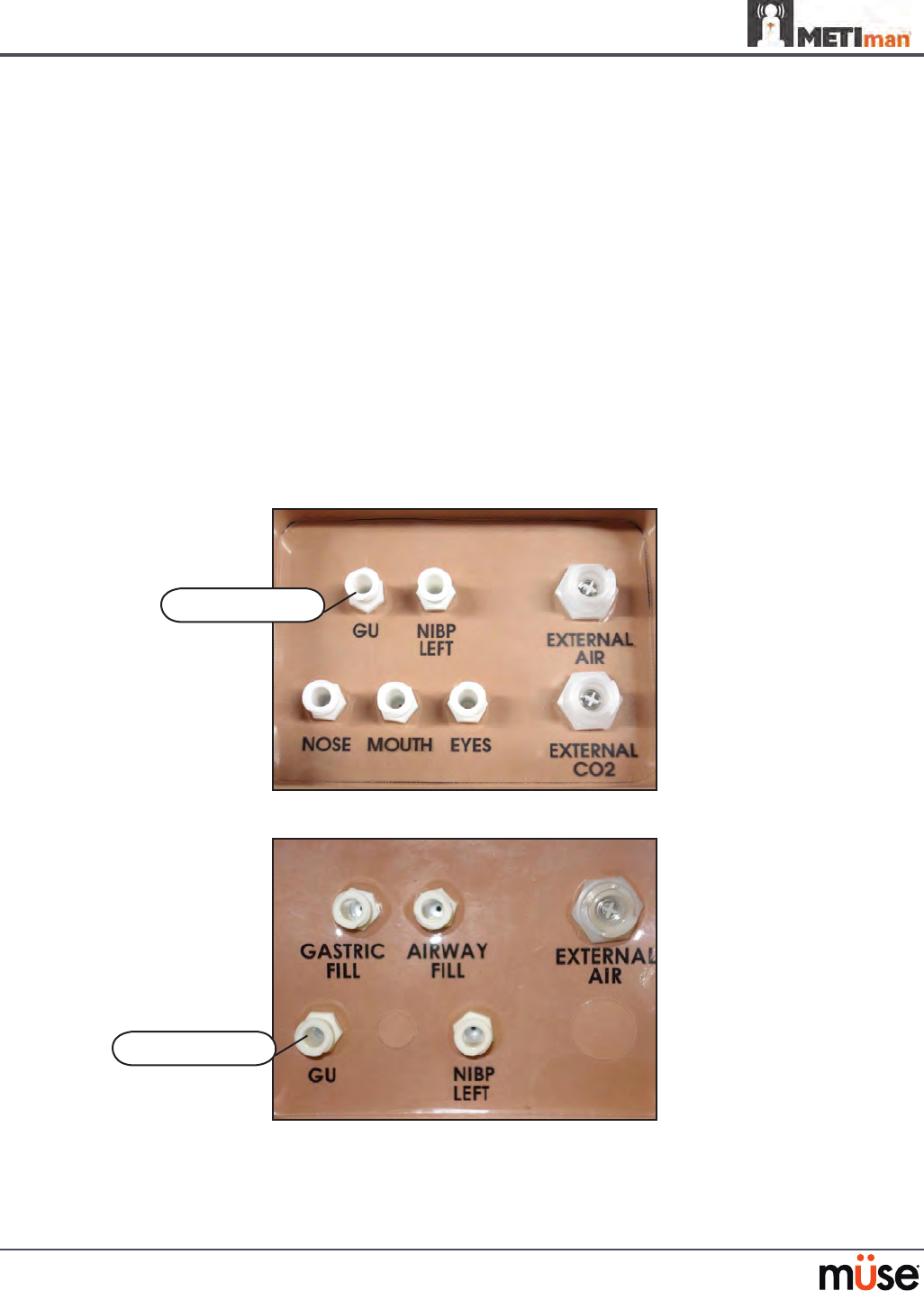
METIman Prehosptial’s Left Shoulder
METIman Nursing’s Left Shoulder
The GU port
The GU port

165
Using METIman
Open the clamp and allow uid to ow into the simulator. There is a reservoir 6.
inside the simulator that lls up with the uid.
Keep the IV bag attached. Adjust the ow rate manually using the roller clamp.
7.
Catheterize the simulator using a 16-Fr urinary catheter lubricated with silicone 8.
spray. The urinary catheter must be fully inserted for the uid to ow.
NOTE: Cleanup is very important when using simulated uids. Please refer to the Care and
Maintenance section for directions on uid removal.
If a small volume of uid is needed to simulate proper urinary catheterization in a eld location,
the internal reservoir may be lled. To ll the genitourinary reservoir, attach a syringe with a
Luer-lock extension set (provided) and inject 60 mL of distilled water into the GU port on the
simulator’s left shoulder.
Changing the Simulator’s Genitalia
METIman comes with male and female genitalia.
To switch genitalia:
Pull apart the Velcro holding the genitalia.
1.
Loosen and remove the urethra connector. This connection may be tight when 2.
genitalia are removed the rst time.
Remove the genitalia.
3.
Attach urethra tube to the urethra connector.4.
Attach the desired genitalia using the Velcro.5.

166
Using METIman
Sounds
A variety of simulated sounds are available to enhance realism. A patient must be running on
METIman for any sounds to be available.
Speech
Speech can be added to simulations using the Vocal Sounds and Speech Sounds features on
the software or by using an external microphone.
Vocal Sounds
A variety of programmable vocal sounds are available. Vocal sounds are male or female based
on the gender of the active patient.
Vocal Sounds
None
Audible Wheezing
Crying
Gagging
Gasping
Groaning
Long loud cough
Long soft cough
Mumbling
167
Using METIman
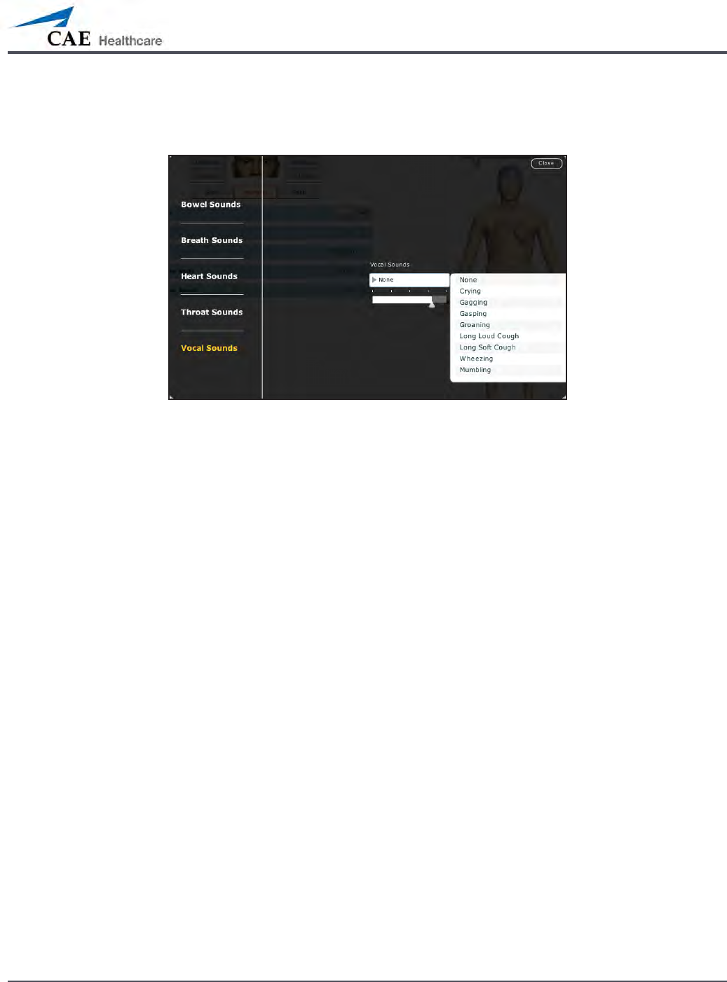
To select a sound from the Vocal Sounds drop-down menu, click the Sounds button on the
Run screen. The Sounds panel appears.
Vocal Sounds Menu
Click Vocal Sounds and select the type of sound desired from the Vocal Sounds drop-down
menu. Vocal Sounds play continuously when selected and are emitted immediately when
selected from the Vocal Sounds drop-down menu. To stop playing one of the vocal sounds,
select None from the list.

168
Using METIman
Speech Sounds
Speech Sounds include a male or female voice that can utter pain rating indicators from 0 to
10, various phrases and a series of other utterances. Unlike Vocal Sounds, Speech Sounds only
play once.
Speech Sounds
Loud Cough
Soft Cough
Short Loud Cough
Short Soft Cough
Scream
Grunt
“Yes”
“No”
“Sometimes”
“Ouch”
“My leg hurts”
“My belly hurts”
“My chest is tight”
“I can’t breathe”
“Ow, that hurts”
“0” through “10” - Pain
Ratings
“Sharp”
“Pressure”
“Aching”
“Dull”
“Stabbing”
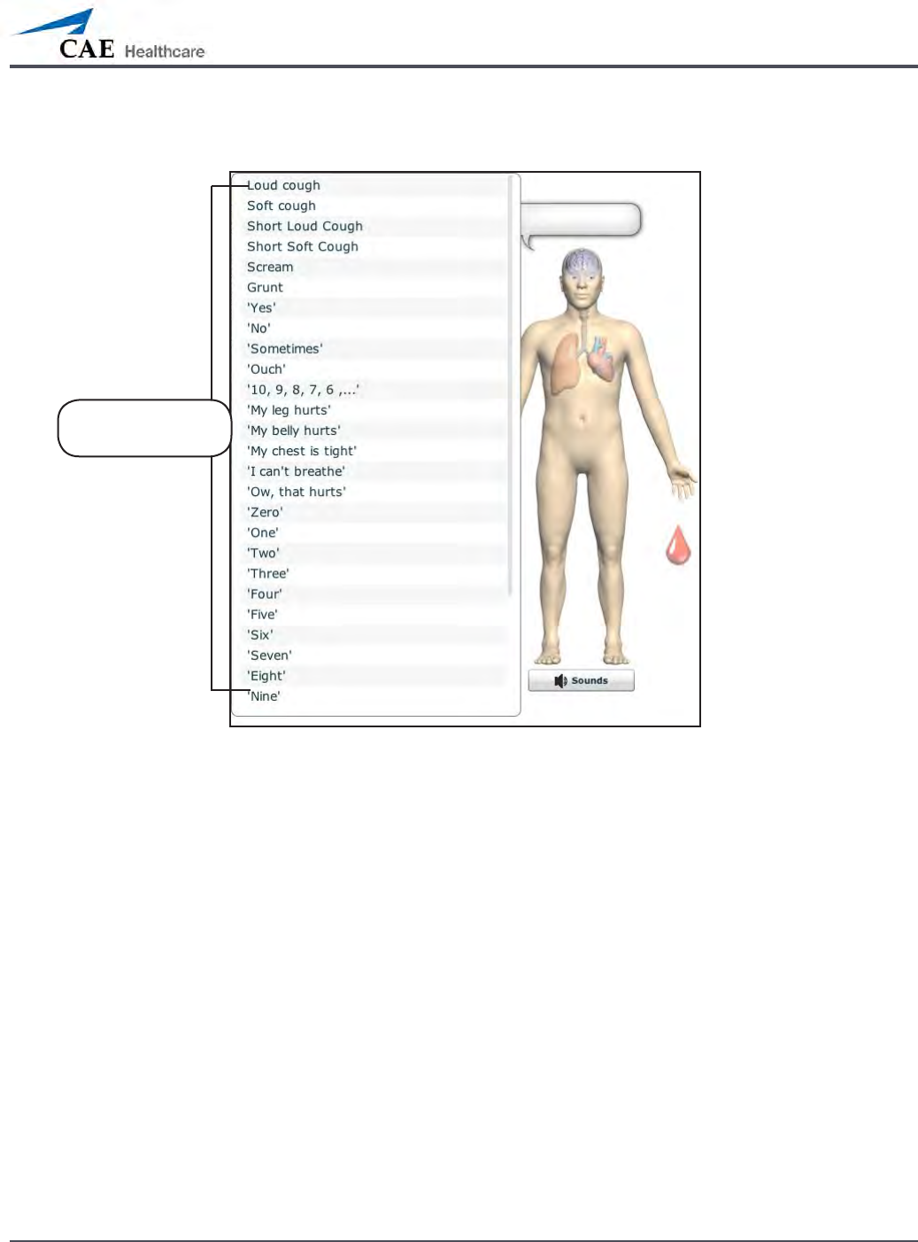
169
Using METIman
To play a Speech Sound, click the Speech balloon. A list of Speech Sounds appears.
The Speech Sounds Menu
Select the desired sound. The sound plays, and the list disappears.
To replay the last sound, click the Play button in the Speech balloon.
The Speech
Sounds menu
170
Using METIman
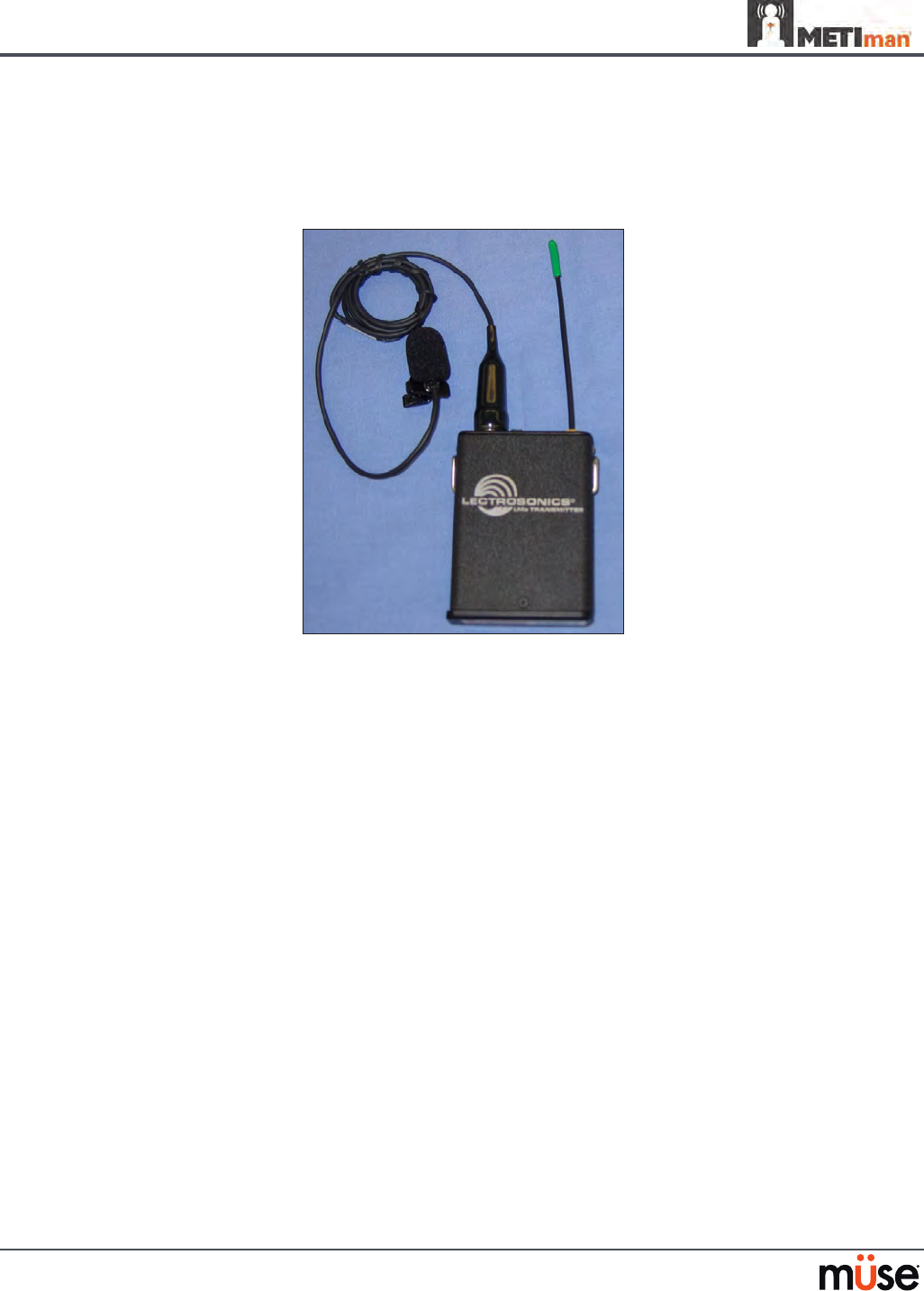
Wireless Voice Capability
In addition to the pre-programmed speech, any response can be transmitted through the
speakers using the wireless microphone.
Wireless Microphone
The microphone volume can be adjusted on the microphone itself using the volume control.
Wireless Voice Link
If a wireless voice link package was included with the METIman simulator, see Appendix B -
Wireless Voice Link on page B-1 for additional instructions.
171
Using METIman
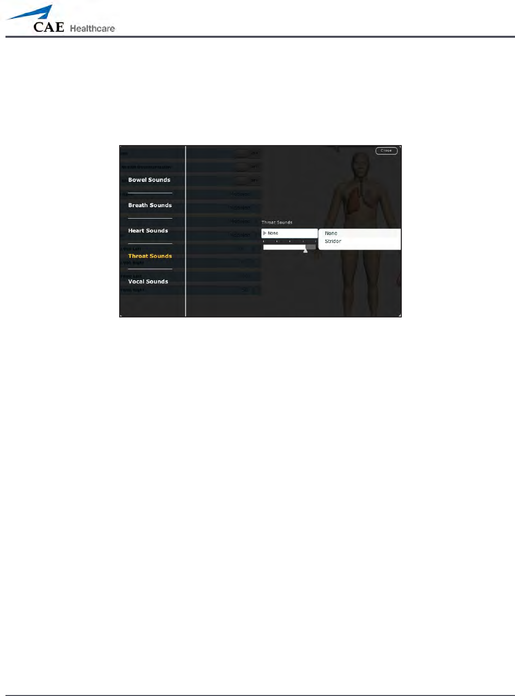
Throat Sounds
Stridor throat sounds can be enabled using the software. Throat sounds can be adjusted by
clicking the Sounds button on the Run screen. When the Sounds panel appears, select Throat
Sounds.
The Throat Sounds Menu
Click the Throat Sounds drop-down menu to change the type of sound. Click and drag the
slider to adjust the volume.
172
Using METIman
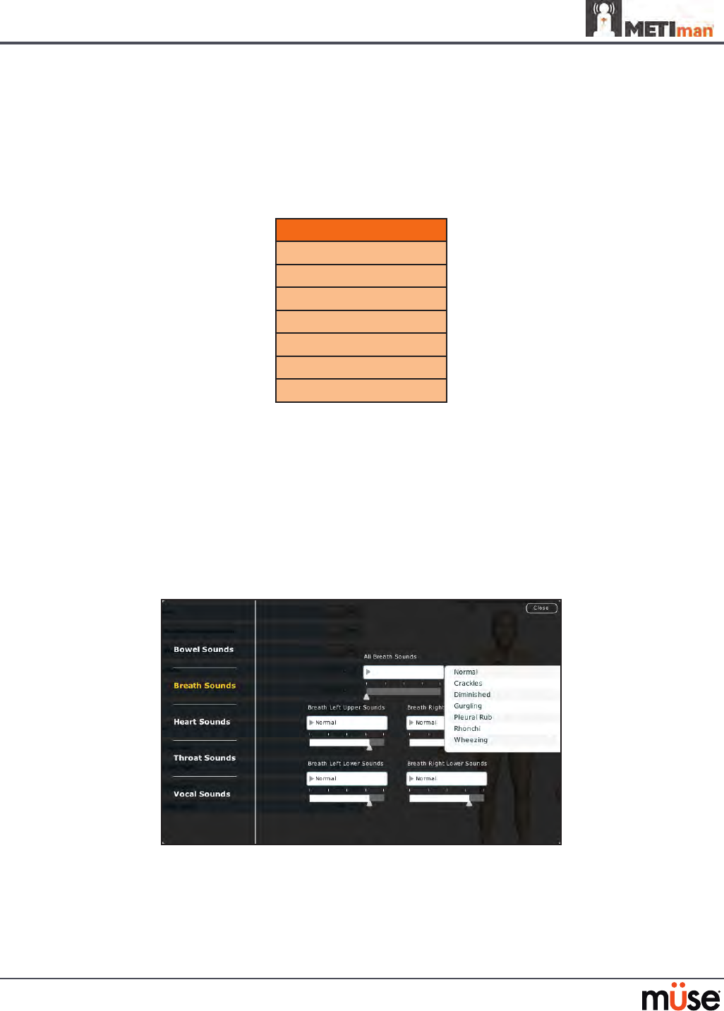
Breath Sounds
Breath sounds are independently synchronized with ventilation of the left and right lungs.
Fourteen speakers, eight anterior and six posterior, provide breath sounds that can be
auscultated. Each of the four quadrants of the torso can be set independently to produce a
particular breath sound.
Breath Sounds
Normal
Crackles
Diminished
Gurgling
Pleura Rub
Rhonchi
Wheezing
Click any one of the Breath Sounds drop-down menus that each control one of four
quadrants to change the type of sound. Click and drag the slider for each location to adjust the
volume.
A patient must be running on a METIman simulator for any sounds to be available.
By default, Normal breath sounds are heard.
Breath sounds can be adjusted by clicking the Sounds button on the Run screen. When the
Sounds panel appears, select Breath Sounds.
The Breath Sounds Menu
173
Using METIman
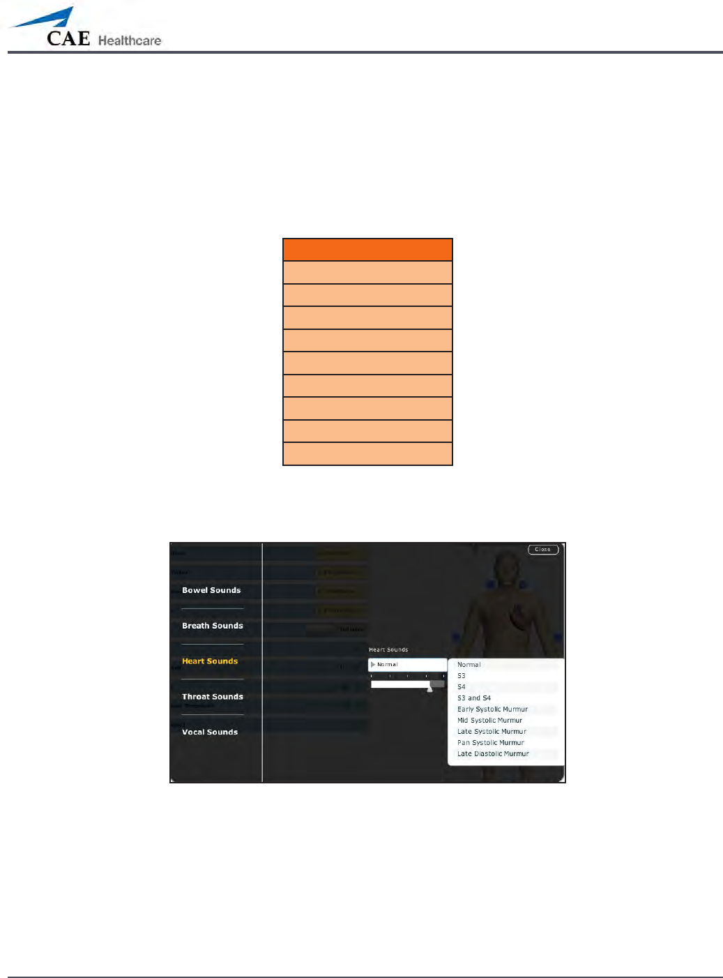
Heart Sounds
Heart sounds emanate from four speakers and are synchronized with the cardiac cycle. Heart
sounds can be auscultated over the left and right sternal border, right lower sternal boarder
and apex.
By default, heart sounds are set to the Normal sound. The following sounds are available:
Heart Sounds
Normal S1-S2
S3
S4
S3 and S4
Early Systolic Murmur
Mid Systolic Murmur
Late Systolic Murmur
Pan Systolic Murmur
Late Diastolic Murmur
Heart sounds can be adjusted by clicking the Sounds button on the Run screen. When the
Sounds panel appears, select Heart Sounds.
The Heart Sounds Menu
Click the Heart Sounds drop-down menu to change the type of sound. Click and drag the
slider to adjust the volume.
174
Using METIman
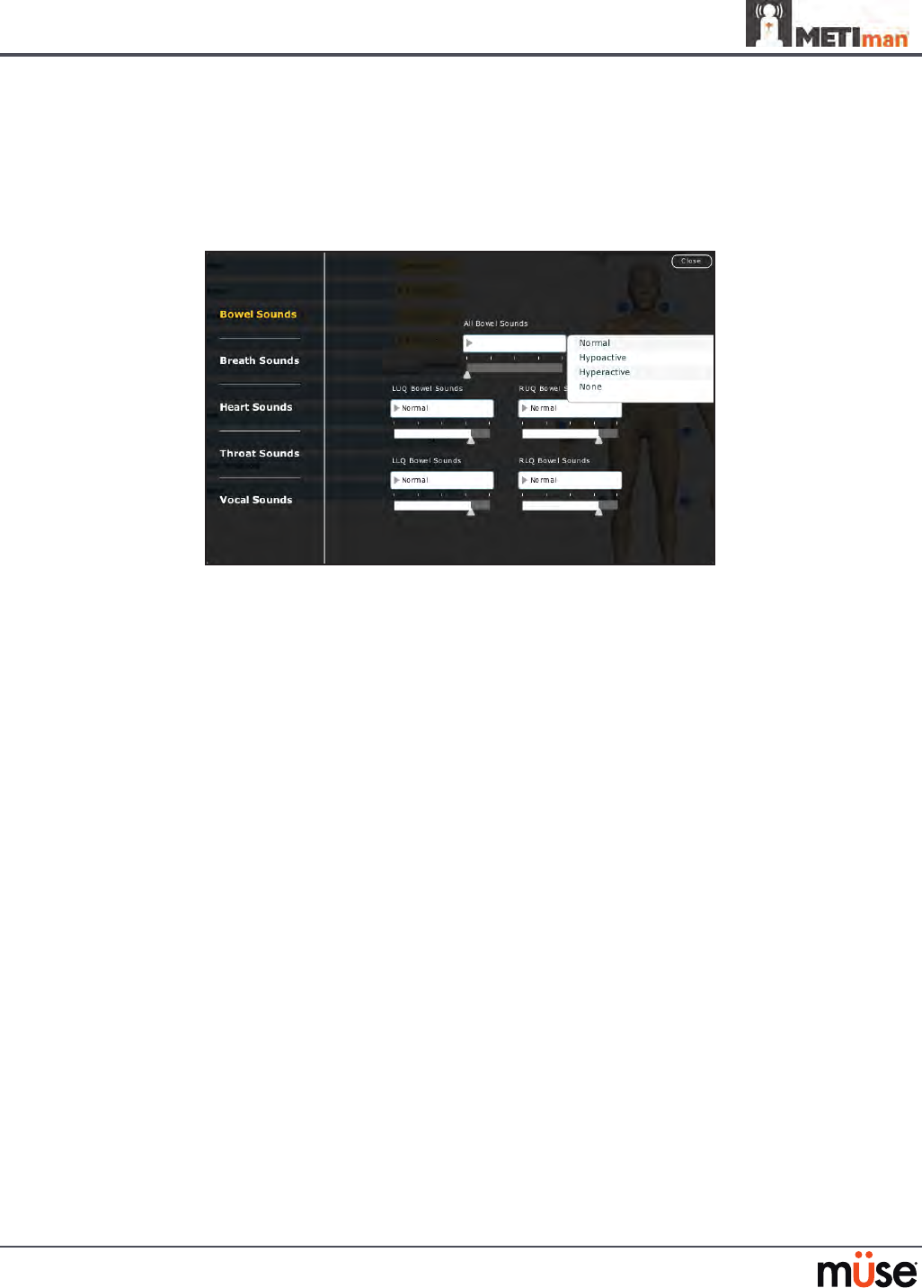
Bowel Sounds
Learners can auscultate bowel sounds over each of four intestinal quadrants: the Upper
Right, Upper Left, Lower Right and Lower Left. The sounds can be independently set in each
anatomical region to Normal, Hypoactive, Hyperactive or None (bowel sounds are absent).
The Bowel Sounds Menu
Bowel sounds can be adjusted by clicking the Sounds button on the Run screen. When the
Sounds panel appears, select Bowel Sounds.
Click any one of the Bowel Sounds drop-down menus that each control one of four quadrants
to change the type of sound.
Click and drag the slider for each location to adjust the volume.
Normal bowel sounds are present by default.

175
Care and Maintenance
Care and Maintenance
Maintaining METIman requires careful treatment of the electronic and mechanical
components. Each time METIman is assembled or disassembled, make sure all components
are properly handled and either removed from or placed into storage correctly.

176
Care and Maintenance
METIman Warranty Programs
General Information
CAE Healthcare patient simulator products come with a one-year Manufacturer’s Warranty
(excluding batteries and consumables). All warranties begin at date of shipment or CAE
Healthcare installation. You may upgrade your rst year Warranty to an Enhanced Warranty
and receive remedial and planned maintenance. To prevent equipment downtime and delays
after your warranty expires, we encourage you to contract for extended maintenance services
for all subsequent years.
Units Out of Agreement
For units no longer under warranty requiring repairs, the Time and Materials service plan will
apply (see Time and Materials section).
To place an out-of-warranty unit under a warranty contract, CAE Healthcare reserves the
right to have the patient simulator inspected by a CAE Healthcare-approved technician at
the customer’s expense. If necessary, the unit would have to be repaired at the customer’s
expense prior to issuance of a warranty contract.
The repairs required as the result of the examination will be quoted on a time and material
basis.

177
Care and Maintenance
How to Contact Customer Service
CAE Healthcare Customer Service Headquarters - United States and Latin America
Monday - Friday from 7:00 a.m. to 6:00 p.m. ET
Toll Free +1 (866) 462-7920
24-hour Hotline +1 (941) 342-5605
Fax +1 (941) 342-5600
Email Address: customerservice@caehealthcare.com
Web URL: www.caehealthcare.com
CAE Healthcare Customer Service - Canada
Monday - Friday from 8:00 a.m. to 5:00 p.m. ET
Toll Free +1 (877) 223-6273
Email Address: can.service@caehealthcare.com
CAE Healthcare Customer Service - Europe, Middle East and Africa (EMEA)
Monday - Friday from 8:00 a.m. to 5:00 p.m. CET
Phone +49 (0) 6131 4950354
Fax +49 (0) 6131 4950351
Email Address: international.service@caehealthcare.com
CAE Healthcare Customer Service - UK and Ireland
Monday - Friday from 9:00 a.m. to 5:00 p.m. GMT
Phone +44 (0)800-917-1851
Email Address: uk.service@caehealthcare.com
Principal hours of operation exclude holiday and non-business days.

178
Care and Maintenance
Contract Period
Warranty contracts are not ordinarily oered for periods of less than one year. However,
multiple-year warranty contracts may be arranged for up to an additional three years.
Discounts are available for purchase of multiple-year contracts.
Limitations of Agreement
Your exclusive remedy for any defective patient simulator is limited to the repair or
replacement of the defective patient simulator.
CAE Healthcare may elect which remedy or combination of remedies to provide at its sole
discretion. CAE Healthcare shall have a reasonable time after determining that a defective
material exists to repair or replace defective material. CAE Healthcare’s replacement material
will be manufactured from new and/or serviceable parts. CAE Healthcare’s agreement
applies to repaired or replaced materials for the balance of the applicable period of the
original warranty or ninety days from the date of shipment of a repaired or replaced material,
whichever is longer. CAE Healthcare warrants its LABOR for 30 days or the balance at the
applicable period of the original warranty, whichever is greater.
CAE Healthcare shall not be liable under this warranty for incidental or consequential
damages, or in the event of any unauthorized repairs or modications have been made or
attempted, or when the product, or any part thereof, has been damaged by accident, misuse
or abuse. This warranty does not cover normal wear and tear, staining, discoloration or other
cosmetic irregularities that do not impede or degrade product performance. Any damage
or malfunction as a result of the installation of software or hardware, not authorized by CAE
Healthcare, will be repaired under the Time and Materials service plan (see Time and Materials
section).
CAE Healthcare’s warranty does not cover products that have been received improperly
packaged, altered or physically damaged. Products will be inspected upon receipt.
Some states in the USA do not allow the exclusion or limitations of incidental or consequential
damages, so the limitations above may not apply to you. This warranty gives you specic legal
rights and you may also have other rights, which vary from state to state.
Return Materials Authorization (RMA)
No product may be returned directly to CAE Healthcare without rst contacting CAE
Healthcare for an RMA number. If it is determined that the product may be defective, you
will be given an RMA number and instructions for product return. An unauthorized return,
e.g., one for which an RMA number has not been issued, will be returned at your expense.
Authorized shipments are to be shipped prepaid to the address on the RMA. Your original box
and packaging materials should be kept for storing or shipping your product. To request an
RMA, please contact Customer Service.
179
Care and Maintenance
System Software Upgrade Support
Customers with current warranty contracts are entitled to receive upgrades to applications
software previously purchased. Installation of the system software is the user’s responsibility.
The System Software Upgrades Support includes software upgrades for base software and
purchased optional software modules.
**This does not apply for major upgrades or technological enhancements.**
Pricing Structure
Time and Materials
For those systems not under agreement, service will be provided as required on a Time and
Material basis:
Description In-House On-Site
Technical Support As quoted at time of repair
CAE Healthcare’s prevailing
labor rate with a minimum of
four hours labor
Material As quoted at time of repair As quoted at time of repair
Travel N/A Priced at CAE Healthcare’s
fully burdened cost plus fee
Principal period of on-site support (customer’s local time) is:
Monday through Friday, 8:00 AM to 5:00 PM (customer’s time zone)•
Holiday and non-business days excluded•
Support outside the principle period is billed at the premium rate (hourly rate x 1.5)•
A minimum of 48 hours notice is required for scheduling an on-site support call. Urgent on-
site support with less that 48 hours notice will be charged at the premium hourly rate.
On-site time is described as the time period commencing from arrival at customer site through
departure from customer site.
180
Care and Maintenance
Breakdown
After each use, METIman should be properly disassembled and stored in a secure place.
To ensure that METIman remains in good working condition, follow the prescribed CAE
Healthcare breakdown procedures below. These procedures are estimated to take less than 30
minutes.
Breakdown Steps
1
2
Stop All Running SCEs
Clean the Simulator and the Fluid System
3Shut Down the Software
4Power o the Simulator
Step 1: Stop All Running SCEs
Stop any running SCEs using the Stop button in the upper right corner of the Müse software
for each SCE.
Step 2: Clean the Simulator and the Fluid System
Refer to the Maintenance Advice on the following pages for detailed instructions.
Step 3: Shut Down the Software
To shut down the Müse software:
Click the Account Name in the lower, right-hand corner of the screen. The Logout/
1.
Shutdown dialog box appears.
Click
2. Logout to exit the software, or click Shutdown to shut down the computer.
To shut down the TouchPro software (optional):
Click the
1. Settings button from the bottom, right-hand corner of the TouchPro screen.
From the Settings menu, click
2. Shutdown. A warning box appears asking if you want to
exit.
Click
3. Shutdown.

181
Care and Maintenance
Step 4: Power O the Simulator
Carefully pull back the skin on METIman’s left hip and hold the power switch for two 1.
seconds. The light on the button begins to blink, indicating shutdown is in progress.
After approximately 30 seconds, the light is o, and shutdown is complete. If the
simulator fails to shut down when the above steps are performed correctly, hold the
power button for ve seconds to force the system to power o
Carefully put the skin back into place for storage.
2.
Maintenance Advice
Simple care and maintenance helps to ensure that METIman stays in good working condition.
Many problems are caused by inadequate or improper maintenance. Perform a thorough
check of the various components each time the simulator is used. Failure to follow these
guidelines can lead to damage not covered by warranty.
General Simulator Care
Avoid the use of writing instruments and sharp objects near the patient simulator to prevent
unattractive markings on or tears in the skin.
Lubricate airway adjuncts, urinary catheters and chest tubes with silicone spray (NOT a water-
based lubricant) prior to insertion.
A mild detergent and warm water will remove most marks and stains. Gently rub the soiled
area with a soft cloth. Do NOT use ABRASIVE soaps or pads.
Prior to using moulage of any kind, CAE Healthcare suggests the application of a very light
coating of petroleum jelly, followed by a light dusting of baby powder, to the
simulator’s skin. This application makes cleaning the skin easier.
If any of METIman’s uid systems have been used, ush out the simulator as described in the
following pages. Failure to ush the systems may cause damage to the simulator.
Storage
When in regular use, METIman’s breakdown procedure and general cleanup should be
sucient to prepare the simulator for storage.
In addition, be certain to follow these instructions:
Storage temperature should not exceed 122° F (50° C) or fall below 41° F (5° C).•
If a soft-sided simulator case is being used, the simulator should lie flat.•
The simulator should NEVER be stored or shipped with fluids in the system.•
182
Care and Maintenance
Care of Electronic Equipment
Install any CAE Healthcare software updates as soon as they become available.
Airway Inspection
METIman is equipped with an anatomically accurate airway that supports the practice of
dicult airway management techniques. In the process of performing these techniques
improperly or aggressively, the upper airway can be damaged.
Because damage can occur, occasional visual inspection of the airway is recommended. Using
the light of a laryngoscope blade or a ashlight, visually examine the airway. While tears in
the upper airway resulting from intubation may be obvious, needle holes in the lower trachea
resulting from techniques such as transtracheal jet ventilation may not be readily apparent.
If damage to the airway is found, small cuts or tears may be reparable with silicone adhesive.
However, for permanent repair of damaged simulators, contact CAE Healthcare Customer
Service.
Replacing the Battery
After approximately four hours of use, the simulator’s battery must be removed to be
recharged or replaced with a charged battery.
WARNING : When handling METIman’s batteries, be sure to adhere to all the cautions
and warnings.
To replace the battery:
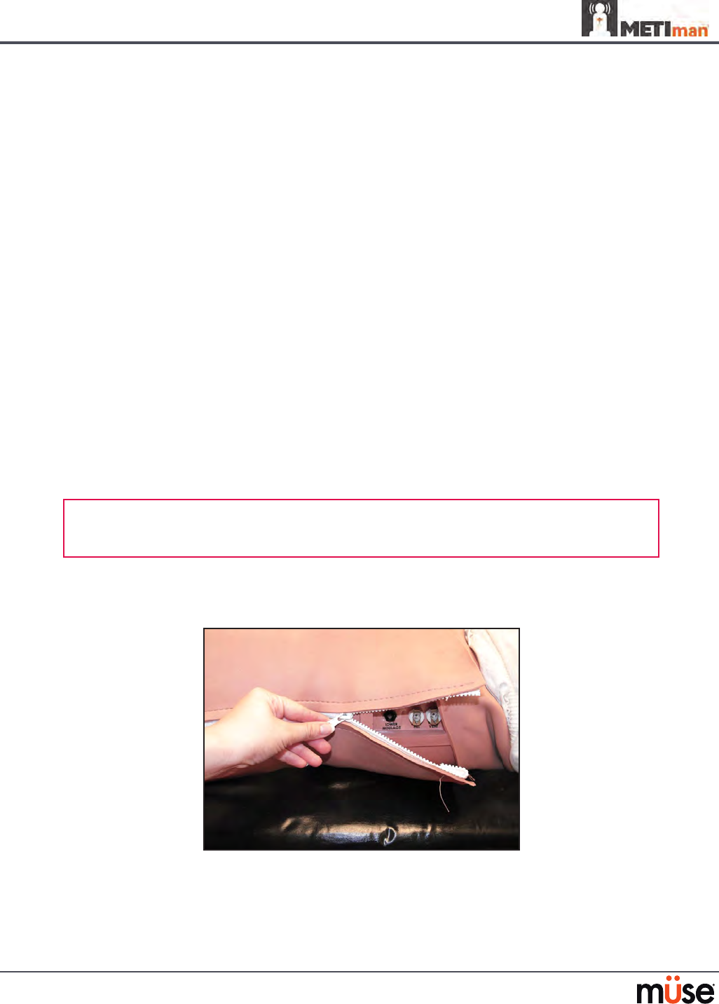
Unzip the chest skin.1.
Unzipping the Chest Skin
183
Care and Maintenance
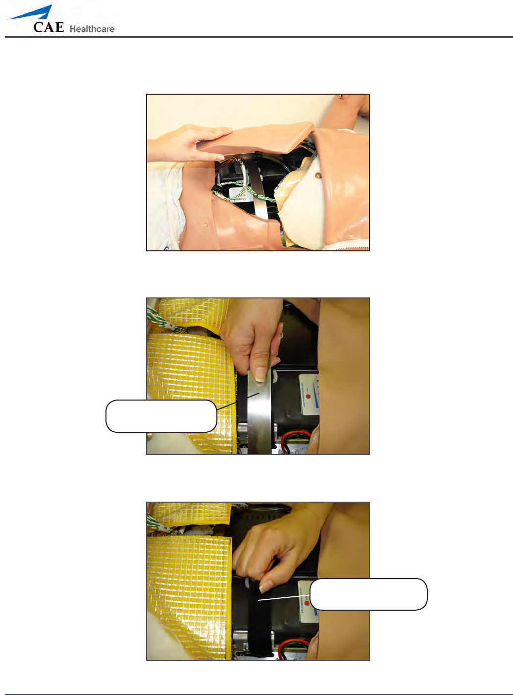
Lift the abdominal insert.2.
Lifting the Abdominal Insert
Remove the abdominal support.3.
Removing the Abdominal Support
Release the Velcro battery tie-down.4.
Releasing the Battery Tie-Down
Remove the
abdominal support
Release the Velcro
battery tie-down
184
Care and Maintenance
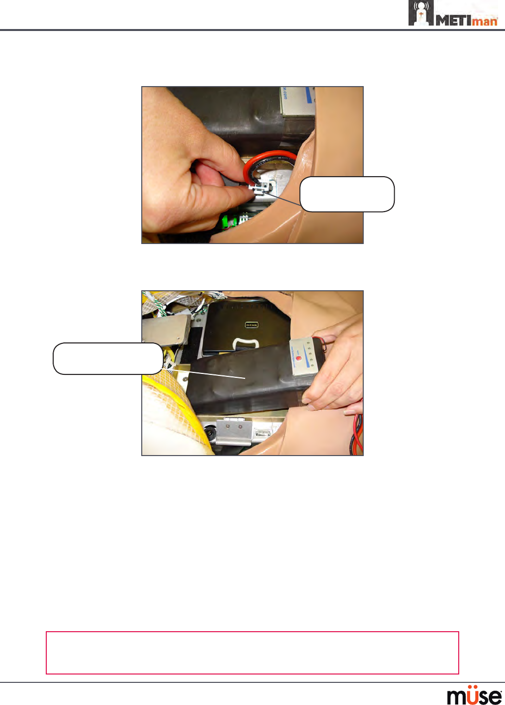
Disconnect the battery leads.5.
Disconnecting the Battery Leads
Remove the uncharged battery.
6.
Removing the Battery
Insert a charged battery and ax the battery tie-down.
7.
Connect the battery leads and replace the abdominal support, ensuring both 8.
ends are secure in the slits.
Replace the abdominal insert and chest skin.
9.
Recharging the Battery
The battery should be recharged after approximately four hours of use.
To recharge the battery, disconnect and remove the battery from the simulator and connect to
the external charger provided.
WARNING: When handling METIman’s batteries, be sure to adhere to all the cautions
and warnings
Remove the
uncharged battery
Disconnect the
battery leads
185
Care and Maintenance
Recharging should take approximately four hours.
IMPORTANT: Never recharge the battery while it is connected to METIman.
Draining Condensation from the Simulator
As part of a regular preventive maintenance schedule, condensation should be drained from
the simulator.
Depending on environmental conditions, moisture may condense inside the compressed air
lines and tanks within the simulator. It is recommended that this uid be drained every 40
hours of operation. In outside, high-humidity conditions, the system should be drained more
frequently.
To drain condensation:
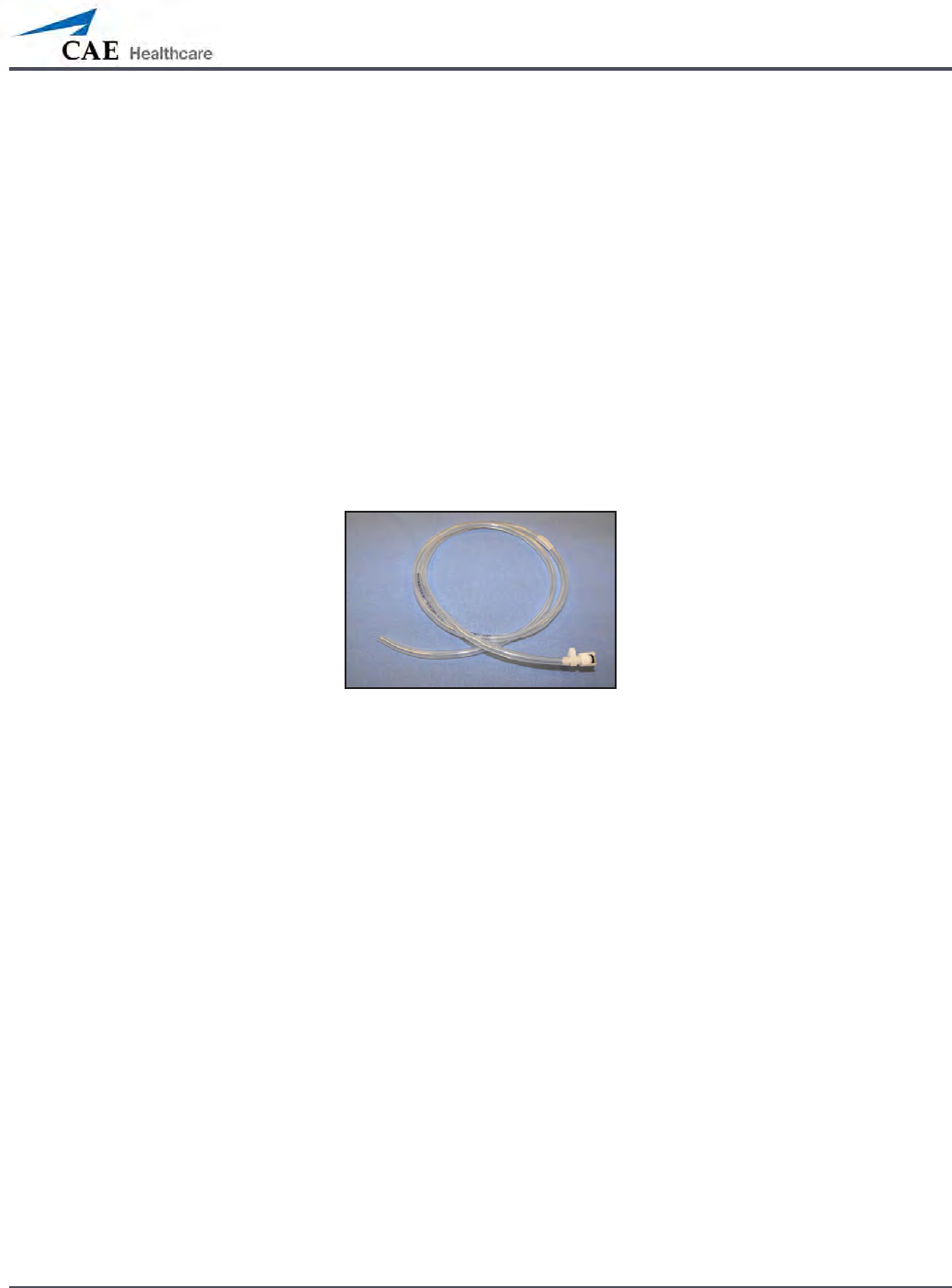
Locate the Condensation Drain Hose included with the Inventory Kit.
1.
Condensation Drain Hose
Bring the hose and a small bucket to the simulator location.2.
Locate the 3. EXTERNAL AIR port on METIman’s left shoulder.
With assistance, place METIman into a supine position.
4.
Power on METIman. Do NOT launch the Müse software. 5.
Allow 60 seconds for the internal compressor to pressurize the system.6.
Power down METIman. 7.
With assistance, raise the left leg 45 degrees.8.
Place the tubing end of the Condensation Drain Hose into the small bucket and 9.
then connect the tting onto the simulator’s drain connector. There will be a
sudden release of pressure into the bucket. Any condensation within the system
drains with this exhaust.
Disconnect the Condensation Drain Hose from the simulator.
10.

186
Care and Maintenance
Cleaning the Simulator and the On-Board Bleeding System
NOTE: A small bucket is recommended to collect wastewater during cleaning and ushing
operations.
To clean and maintain the simulator and On-Board Bleeding system:
Remove and clean the wound haptics.
1.
Connect the beige-colored “ll” connector from the Trauma Fill Tank to the hip, but 2.
do not connect the white “vent” connection.
Open the yellow Pressure Relief knob clockwise on the Trauma Fill Tank or loosen
3.
its Fill Lid so the tank is able to vent during this draining process.
With the wound umbilicals in place, put the ends of both wound umbilicals into a
4.
wastewater bucket.
From the Müse home screen, click the
5. System Administration button in the top
right of the screen.
From the Maintenance screen, click
6. Flush System. The uid begins to drain.
Verify both channels produce a high, steady ow.
7.
When uid stops owing from either wound umbilical, detach the Fill Tank from 8.
the simulator.
When uid stops owing from the lower wound umbilical, detach from the
9.
simulator.
When uid stops owing from the upper wound umbilical, detach from the
10.
simulator.
Click
11. Done on the Maintenance screen. The uids are now drained.
Empty the wastewater bucket.
12.
Rinse out the Trauma Fill Tank and ll with approximately 1 liter of clean, distilled 13.
water.
Pump this uid into the simulator
14. .
Repeat Steps 3 through 7 and 9 through 15 until the uid exiting the simulator
15.
runs clear.
Empty the Fill Tank and dry the wound umbilicals with a towel before storage.
16.
NOTE: It takes two to three minutes for this nal ush.
Once a month, it is advised to ush the system with a mix of 50% distilled water
and 50% white vinegar to keep mineral and algae buildup to a minimum. Always
perform the steps for Flushing the Simulator afterward to remove vinegar.

187
Care and Maintenance
Cleaning the Trauma Fill Tank
To prolong the life of the Trauma Fill Tank assembly and the uid reservoirs, wash and ush the
tank and connections after each use with clean distilled water.
NOTE: A small bucket is recommended to collect wastewater during cleaning and ushing
operations.
Do NOT store liquids in the Trauma Fill Tank. If simulated blood mixtures are stored in the
tank, they may clog the system when they dry and possibly damage the seals, lter and other
components.
Remove and rinse the Overow Bottle.
1.
Remove and rinse the Pump Assembly.2.
Rinse the tank to remove all traces of the simulated blood.3.
Pour 480 mL (16 oz) of distilled water into the tank and reinstall the Pump 4.
Assembly. (The Overow Bottle holds 16 ounces.)
Place the Overow Bottle lid with umbilical attached into the wastewater bucket.
5.
Attach the ll (blue-labeled) and vent (yellow-labeled) ttings together at the 6.
other end of the umbilical.
Pump the tank 25 times while making sure the wastewater is going into the
7.
bucket.
Allow the tank to empty completely (the remaining air pressure will purge the
8.
uid from the lines.
Reinstall the lid onto the Overow Bottle and place the bottle back onto the tank
9.
assembly.
Remove the Pump Assembly and pour any remaining uid out of the tank. Then,
10.
reinstall the pump.
Disconnect the ll and vent ttings from each other and wrap the Trauma Tank
11.
Umbilical around the neck of the tank.
Always depressurize the tank, remove trauma uid and clean the tank before performing
maintenance. The pump assembly may need periodic lubrication. Call CAE Healthcare
Customer Service for details if the pump loses the ability to create pressure, squeaks loudly or
is dicult to move.
188
Care and Maintenance
Cleaning the In-Line Filter
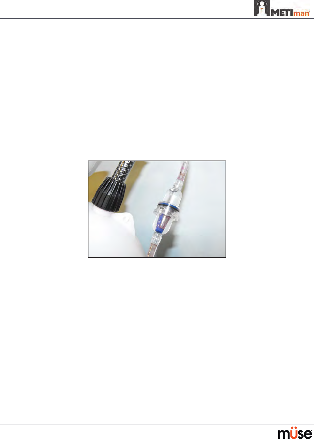
To clean the in-line lter:
Grasp both ends of the in-line lter and twist counterclockwise.
1.
Pull apart both ends of the lter to separate.2.
Remove the blue lter cone from the encasement. Do NOT remove the black 3.
rubber seal.
Using a 60 mL syringe with distilled water, push uid from the outside of the blue
4.
lter cone to the inside, removing all debris.
Repeat process until all debris is removed.
5.
Re-assemble the in-line lter, ensuring the black rubber seal is in place at the base 6.
of the blue lter cone.
The In-Line Filter

189
Care and Maintenance
Troubleshooting the Trauma Fill Tank
Before making any repairs, ALWAYS depressurize the tank, remove all trauma solution and
clean the tank.
Problem Cause Solution
Tank can be pressurized, but only
air comes out.
Siphon tube has detached from
insert.
Remove hose from tank and reinsert
siphon tube.
Pressure does not build up. No
uid is transported to simulator.
(1) Pump assembly not sealed tightly
into tank or
(2) Damaged pump cylinder
gasket or o-ring or
(3) Tank pressure relief valve is
set to “open.”
(1) Thoroughly clean pump
cylinder gasket or o-ring and
surrounding area and apply a light
coating of silicone to pump gasket or
o-ring.
(2) Contact CAE Healthcare for
service.
(3) Turn valve until it returns to a
“sealed” position.
Simulator ll time is too long
(more than 5 minutes).
(1) Not enough strokes applied
to create pressure or
(2) The in-line lter is dirty or
(3) The umbilical is
disconnected at Overow
Bottle or
(4) Too much uid in ll tank.
(1) Pump 25 to 35 times for best
performance.
(2) Clean lter.
(3) Reconnect the overow tting.
(4) The Trauma Fill Tank works best
with 1 gallon (3.6 liters) of uid
inside. If greater amounts of
uid are used, tank may require
additional pumps as uid is
transported to simulator.

190
Care and Maintenance
Emptying and Flushing the Chest Tube Reservoir
Removing uids from the Chest Tube reservoir and the Chest Tube system requires the same
steps.
To empty the Chest Tube reservoir or ush the Chest Tube system, have a chest tube and a
basin to catch uid in place. Use a syringe to slowly push air through the appropriate CHEST
TUBE port until only air ows through the chest tube.
Flushing the IV Lines
To ush the IV lines:
Connect an empty IV bag to the
1. IV DRAIN port.
Using a syringe, slowly push air into the
2. IV FILL port. The uid drains out of the IV
DRAIN port.
Continue to push air until empty.
3.
Emptying the Genitourinary Reservoir
To empty the Genitourinary reservoir, have a catheter in place and a basin to catch uid. Use a
syringe to slowly push air through the GU port until only air ows through the catheter.
Emptying the Head Secretions Lines (Prehospital Only)
To remove uid from the Head Secretions lines, connect a syringe to the NOSE port and
vacuum out uid until empty. Repeat this process for the MOUTH and EYES ports.
Emptying the Airway Secretions Reservoir (Nursing Only)
To empty the Airway Secretions reservoir, connect a 60 mL syringe to the AIRWAY FILL port
and vacuum out uid until empty.
Flushing the Subclavian Catheter (Nursing Only)
When ushing the Subclavian Catheter, the catheter must be in place.
To ush the Subclavian Catheter:
Connect an external drain to the
1. IV DRAIN port and place a basin to catch uid.
Using a syringe, slowly push air into the
2. IV FILL port. The uid drains out of the IV
DRAIN port.
Continue to push air until empty.
3.
Using the same syringe, push air through the Subclavian Catheter until empty. 4.

191
Care and Maintenance
Handling CO2 Canisters (Prehospital Only)
Careful handling is required in the use of CO2 canisters. Please read and follow all appropriate
cautions and warnings.
Removing CO2 Canisters from the Regulator
The following instructions describe how to safely remove the CO2 canister from the regulator
assembly for replacement or shipping.
CAUTION: If unsure that CO2 canister is empty, eye and hand protection must be worn to
protect from release of freezing gas or liquid.
Remove the CO
1. 2 regulator assembly from the simulator.
While holding the regulator assembly rmly, slowly unscrew the CO
2. 2 canister
from the regulator. There is a small relief hole in the side of the regulator from
which any remaining CO2 will bleed. If this should happen, no harm will be done
to system, but it is rather noisy and the rapid release of CO2 gas can freeze the
canister’s surface and cause frostbite to unprotected skin.
Continue unscrewing the canister until it is free from the assembly.
3.

192
Care and Maintenance
Important Canister Information
The 16 Gram CO2 Canister with threaded neck is available at most sports equipment retailers
- most often used for bicycle tire inators. We recommend purchasing Leland brand canisters
(P/N 82122Z), which are also available from CAE Healthcare.
Punctured canisters are considered to be empty. No residue remains in the canister after use.
The steel used is a low carbon type, which rusts if disposed in a landll. If your community
requires recycling, then place with normal household recycling.
CO2 Canisters are considered by the U.S. Department of Transportation to be “Other Regulated
Materials - Domestic” (ORM-D). Ground shipping containers must be clearly marked with this
label. CO2 Canisters are considered hazardous material when oered for air transportation, so
dierent rules apply. Contact carrier for details and instructions.
Related CAUTIONS/WARNINGS
CO2 Canister
Store the CO• 2 canisters in a dry location between 32° and 104° F (0 to 40°C).
Do not expose the CO• 2 canister to heat above 140° F, as rupture may occur.
Never point the CO• 2 canister towards your face or someone nearby.
Use only CAE Healthcare specified CO• 2 canisters.
CO2 Regulator Assembly
Care must always be taken when using high-pressure equipment.•
Do not disassemble or alter regulator.•
Dry completely if the regulator becomes wet.•
Discontinue use of this equipment if leakage or visible damage is evident.•
Use of Equipment
Canister end becomes punctured when screwed into regulator base and therefore •
should not be removed until empty.
Unscrewing canister before it is empty will result in sudden release of all high-pressure •
gas with a possibility of liquid CO2 spray. Unprotected skin could receive freezing
burns.
Wear protective gloves and eye protection when removing canister from regulator •
assembly.
Remove CO• 2 canister from regulator assembly when shipping simulator.

193
Condition Guidelines for Programming METIman
Condition Guidelines for Programming METIman
This card is intended to help you select Müse conditions to achieve desired vital signs
within each programmed state. All four conditions should be programmed into each
state in the order presented below.
Respiratory: Desaturation•
Cardiovascular: Blood Pressure•
Cardiovascular Heart Rate•
Respiratory: Respiratory Rate •
The Müse software is physiologically driven. When using multiple conditions
(e.g., Desaturation + Hypertension + Tachycardia + Tachypnea), physiological
regulatory mechanisms such as the baroreceptor reex and ventilatory control cause
compensatory changes within parameters. To achieve the desired vital sign, select one
condition level, above (greater) or below (less), to achieve the desired physiological
eect.
Respiratory: Desaturation
Desaturation SpO2 Value
Reset 98%
High 90s 96-97%
Mid 90s 94-96%
Low 90s 91-93%
High 80s 87-90%
Mid 80s 84-86%
Low 80s 80-83%
High 70s 77-80%
Mid 70s 74-77%
Low 70s 69-71%
Less than 70 <69%
194
Condition Guidelines for Programming METIman
Cardiovascular: Blood Pressure
Hypertension Hypotension
Reset 110s/70s Reset 110s/70s
Increased 120s/80s Decreased 100s/70s
Pre-Borderline 130s/80s Pre-Borderline 100s/60s
Borderline 140s/90s Borderline 90s/50s
Mild 150s/90s Mild 80s/40s
Moderate 160s/100s Moderate 70s/40s
Severe 170s/100s Severe 60s/30s
Profound 190s/110s Profound 50s/30s
Extreme 220s/120s Extreme 40s/30s
195
Condition Guidelines for Programming METIman
Cardiovascular: Heart Rate
Tachycardia Bradycardia
Reset 70s Reset 70s
Increased High 70s Decreased Mid 60s
Elevated 80s Pre-Borderline Low 60s
Pre-Borderline 90s Borderline Mid 50s
Borderline 100s Intermediate Low 50s
Intermediate 110s Mild High 40s
Mild 120s Moderate Mid 40s
Moderate 130s Severe Low 40s
Severe 140s Extreme Mid 30s
Supra 150s Acute Low 30s
Profound 160s
Extreme 170s
Acute High 170s
196
Condition Guidelines for Programming METIman
Respiratory: Respiratory Rate
Tachypnea Bradypnea
Reset 11 Reset 11
Increased 15 Increased 10
Elevated 18 Intermediate 9
Borderline 20 Mild 7
Intermediate 22 Moderate 6
Mild 25 Severe 5
Moderate 28 Profound 3
Severe 31 Extreme 2
Profound 33
Extreme 36

A-1
Appendix A – Parameter Descriptions
Appendix A – Müse Parameter Descriptions
The Müse software has a number of parameters that control the physiological features of
METIman The parameters are grouped by category: Neurological, Respiratory, Cardiovascular,
Fluids and Sounds. The following is a brief description of each parameter.
Each parameter description lists the default settings for the Stan D. Ardman II and Norma L.
Female patients as well as the ranges, if available, for all patients.
Neurological
METIman can simulate a variety of neurological clinical indicators, such reactive eyes and
convulsions.
Neurological Parameters
Eyes: Pupil Size
Ey es: Blink Speed
Convulsions
ICP
NMB
Te mperature: Body
Te mperature: Blood
Eyes
Each eye has reactive pupils and eyelids that blink and close.

A-2
Appendix A – Parameter Descriptions
Eyes: Pupil Diameter
These parameters are used to control the diameter of the pupils in the eyes. Each eye has
reactive pupils and functional eyelids that blink.
Currently, there are four pupil options that are used to control the diameter of the pupils in
both eyes: Reactive, Non-Reactive, Pinpoint or Blown.
When the Eyes are set to Reactive, the pupils re-size in response to changes in lighting
condition. If both pupils are set to Reactive, both pupils re-size in a consensual manner.
The Non-Reactive, Pinpoint and Blown settings allow the user to x one or both pupils to a
specic size. The Non-Reactive setting xes pupils to a normal size, the Pinpoint setting xes
pupils in the pinpoint position and the Blown setting xes pupils in the blown position.
Default: Reactive
Eyes: Blinking
In Auto mode, the eyelids are normally blinking under the following conditions: Minute
Ventilation is greater than 1500 mL, SpO2 is greater than 70% and neuromuscular blockade
(NMB) is less than 30%.
The Blinking and Closed settings allow the user to have one or both eyes either blinking or
closed and override the automatic response.
Default: Auto
The Slow, Normal and Fast parameters control the eyelid blinking frequency. Presently,
blinking frequency is not linked to the physiological models. However, the response can be
done “on the y” or scripted using the Scenario Designer.
Default: Normal
Convulsions
The Convulsions parameter is used to simulate the presence of convulsions. They are either
ON or OFF.
Default: O

A-3
Appendix A – Parameter Descriptions
Intracranial Pressure (ICP)
The ICP parameter is used to set the ICP displayed as a numeric value on the TouchPro monitor.
The base value is set at 8 mmHg. This parameter is uninuenced by physiological models.
Default: 8 mmHg
Range: 0.0 mmHg - 65.0 mmHg
Neuromuscular Blockade (NMB)
The pharmacokinetic and pharmacodynamic models based on the neuromuscular blocking
agents administered and the time course of their injection automatically determines the
degree of NMB. For some educational applications, however, the instructor may wish to set a
xed degree of neuromuscular blockade that remains stable for an indenite period. This can
be accomplished using the NMB parameter. The default setting instructs the pharmacologic
models to determine the degree of neuromuscular blockade based upon the drugs injected
and their pharmacologic properties.
When a positive numeric value is assigned to this parameter, the degree of NMB is set to that
level. For example, 80% NMB causes the simulator to set the degree of NMB to 80%, regardless
of the presence (or absence) of neuromuscular blocking drugs. Clinically, the spontaneous tidal
volume is markedly reduced.
Default: Modeled
Range: 0% - 100%
Temperature: Body
The temperature measured at the body surface can be set using this parameter and can be
displayed on the Patient Status Display and TouchPro software.
The body temperature is not linked to the physiologic models. However, changes can be made
“on the y” or scripted using the Scenario Designer.
Default: 36.5° C
Range: 32.0° C - 42.0° C

A-4
Appendix A – Parameter Descriptions
Temperature: Blood
The arterial blood temperature can be set using the Temperature: Blood parameter. The
arterial blood temperature can then be displayed on the Patient Status Display and TouchPro
software. Note that changes in arterial temperature may alter the shape of the standard
oxyhemoglobin dissociation curve. As temperature increases or pH decreases, more oxygen is
released from hemoglobin and thus the patient’s saturation decreases. The inverse is also true.
Default: 37° C
Range: 32.0° C - 42.0° C
Respiratory Parameters
Respiratory Parameters
Swollen Tongue
Airway Occluder (Prehospital Only)
Laryngospasm (Prehospital Only)
Ne edle Decompression (Left and Right) (Prehospital Only)
Br onchial Occlusion
Respiratory Rate

A-5
Appendix A – Parameter Descriptions
Respiratory Parameters
SpO2
NMB
Tidal Volume
In trapleural Volume: Left
In trapleural Volume: Right
Chest Tube Flow: Left
Ch est Tube Flow: Right
Swollen Tongue
This parameter is used to create tongue swelling. The tongue is either Swollen or Not Swollen.
The Not Swollen setting returns the tongue to its normal anatomic state.
Default: Not Swollen
Options: Not Swollen, Swollen

A-6
Appendix A – Parameter Descriptions
Airway Occluder (Prehospital Only)
Using the Airway Occluder parameter, swelling of the posterior oropharynx can be activated
to obstruct the view of the larynx and prevent intubation but allow mask ventilation of the
patient’s lungs, thereby creating a “cannot intubate, can ventilate” scenario.
Default: O
Laryngospasm (Prehospital Only)
Use the Laryngospasm parameter to simulate a laryngospasm. A laryngospasm actuator
closes the patient’s vocal cords and prevents both ventilation and intubation. When activated
with the Airway Occluder parameter, a “cannot ventilate, cannot intubate” crisis scenario is
achieved.
Default: O
Needle Decompression (Left and Right) (Prehospital Only)
The Needle Decompression parameter is used to activate the Needle Decompression
hardware in the simulator to relieve a pneumothorax in the simulator. This causes a rush of
air to be heard on successful decompression. The amount of decompression is automatically
subtracted from the Intrapleural Volume set.
Default: O
Bronchial Occlusion
Turning on the Bronchial Occlusion parameter completely obstructs the right or left bronchi,
simulating a lower airway obstruction (e.g., mucus plug). Improper intubation creates a main-
stem occlusion, yielding an inability to ventilate the lungs. However, the right and left bronchi
are not occluded individually.
Default: O
Respiratory Rate
The Respiratory Rate parameter is used to set the respiratory rate to a given number of
breaths per minute. Once set, arterial oxygen and carbon dioxide values have no eect on the
resulting respiratory rate, but continue to inuence other components of the physiological
models. The patient continues to breathe at the set number of breaths per minute, regardless
of the arterial oxygen or carbon dioxide levels.

A-7
Appendix A – Parameter Descriptions
For example, when the respiratory rate is set to 10 breaths per minute, the respiratory rate
remains at 10 breaths per minute, regardless of arterial oxygen or carbon dioxide levels. In such
situations, the patient can only respond to arterial oxygen or carbon dioxide levels by adjusting
the Tidal Volume parameter.
Default: Modeled
Range: 4 breaths per minute - 40 breaths per minute
SpO2
The SpO2 parameter is used to override the normal pulmonary circulation and set the SpO2 at a
xed numeric value, regardless of the oxygen applied. Resetting to Modeled returns control of
the underlying SpO2 to the physiological models.
Default: Modeled
Range: 0% - 100%
Neuromuscular Blockade (NMB)
The degree of NMB is automatically determined by pharmacokinetic and pharmacodynamic
models, which are based on the neuromuscular blocking agents administered and the time
course of their injection. For some educational applications, however, the instructor may
wish to set a xed degree of neuromuscular blockade that remains stable for an indenite
period. This can be accomplished using the NMB parameter. The default value instructs the
pharmacologic models to determine the degree of neuromuscular blockade based on the
drugs injected and their pharmacologic properties.
When a positive numeric any other positive value is assigned to this parameter, the degree of
NMB is set to that level. For example, 80% NMB causes the simulator to set the degree of NMB
to 80%, regardless of the presence (or absence) of neuromuscular blocking drugs. Clinically, the
spontaneous tidal volume is markedly reduced.
Default: Modeled
Range: 0% - 100%
Tidal Volume
The Tidal Volume parameter is used to set the tidal volume to a given volume per breath.
Once Tidal Volume is set to a numeric value, arterial oxygen and carbon dioxide values have no
eect on the tidal volume, but continue to inuence other components of the physiological
models.
For example, with the tidal volume set to 600 mL in the adult simulator, the tidal volume

A-8
Appendix A – Parameter Descriptions
remains a constant (set) 600 mL even in the event of falling arterial oxygen levels. In such
situations, the patient can only respond to arterial oxygen or carbon dioxide levels when the
respiratory rate is adjusted.
Default: Modeled
Range: 0 mL- 2500 mL
Intrapleural Volume (Vol): (Left and Right)
The Intrapleural Vol parameters allow intrapleural volume to accumulate, for example, as
happens during pneumothorax, hydrothorax or hemothorax.
To simulate a pneumothorax, set the corresponding Intrapleural Vol to a value greater than 0
mL. Values more than 1500 mL reduce the corresponding lung volume signicantly. The breath
sounds are automatically diminished on the appropriate side due to decreased ventilation of the
aected lung.
Default: 0
Range: 0 mL - 2500 mL
Chest Tube Flow: (Left and Right)
The Chest Tube Flow parameter is used with the chest tube feature of the simulator. The Chest
Tube Flow species the rate at which uid can be removed from the simulated pleural space via
a chest tube drainage system. As the chest tube drains, the volume is automatically subtracted
from the set amount of Intrapleural Volume.
Default: 50 mL per minute
Range: 0 mL per minute - 50 mL per minute
Cardiovascular Parameters
Cardiovascular Parameters
Blood Pressure
Heart Rate
Cardiac Rhythm

A-9
Appendix A – Parameter Descriptions
Cardiovascular Parameters
Arterial Catheter
Ce ntral Venous Catheter
PA Catheter
PA Balloon
Deb
Pacing Current
Pacing Rate
Pa cing Capture Threshold
Cold Fluid Inject
Blood Pressure
The Blood Pressure parameter is used to override the physiological modeling for blood pres-
sure. The systolic and diastolic blood pressures can both be set to xed numeric values, regard-
less of interventions performed. Resetting the parameter to Modeled returns control of the
underlying Blood Pressure to the physiological models.
Default: Modeled
Range: Systolic 20 mmHg - 200 mmHg
Diastolic 10 mmHg - 200 mmHg
Heart Rate
The Heart Rate parameter is used to set the heart rate to a given (xed) number of beats per
minute. Once the heart rate is set to a numeric value, administered drugs or intravascular
volume changes have no eect on the heart rate, but continue to inuence other components
of the physiological models. Use this parameter to “x” or set the heart rate to a specic
number.
Default: Modeled
Range: 30 beats per minute - 220 beats per minute

A-10
Appendix A – Parameter Descriptions
Cardiac Rhythm
The Cardiac Rhythm parameter is used to change the patient’s underlying cardiac rhythm
displayed on the Patient Status Display, TouchPro software or physiological monitor. To change
the cardiac rhythm, click the Cardiac Rhythm parameter and select the desired rhythm from
the available list. If a number appears following the cardiac rhythm on the list, this overrides
the heart rate to the rate indicated.
Default: Modeled
Options: Modeled
Asystole
Atrial Enlargement, Left
Atrial Enlargement, Right
Atrial Fibrillation
Atrial Fibrillation: HR 120
Atrial Fibrillation: HR 80
Atrial Flutter with 2:1 AV Conduction
Atrial Flutter: HR 150
Atrial Tachycardia
AV Block, First-Degree
AV Block, Second-Degree - Mobitz I
AV Block, Second-Degree - Mobitz II
AV Block, Third-Degree
Bundle Branch Block, Incomplete Right
Bundle Branch Block: Left
Bundle Branch Block, Left with PVC 25%
Bundle Branch Block: Right
Hypercalcemia
Hyperkalemia
Hypertrophy, Biventricular
Hypertrophy, Left Ventricular
Hypertrophy, Right Ventricular
Hypocalcemia
Hypokalemia
Hypothermia
Junctional
Junctional: HR 50
Long QT Syndrome
Myocardial Infarction with LBBB
Myocardial Infarction, Anterior

A-11
Appendix A – Parameter Descriptions
Myocardial Infarction, Anterolateral
Myocardial Infarction, Inferior
Myocardial Infarction, Lateral
Myocardial Infarction, Posterior
Myocardial Infarction, Septal
Myocardial Ischemia: Mild
Myocardial Ischemia: Moderate
Myocardial Ischemia: Moderate with PVC 10%
Myocardial Ischemia: Severe
Paroxysmal Junctional Tachycardia
Paroxysmal Junctional Tachycardia: HR 130
Pericarditis
Premature Atrial Contraction
Premature Ventricular Contraction 10%
Premature Ventricular Contraction 25%
Pulseless Electrical Activity
Sinus
Sinus Bradycardia
Sinus Bradycardia: HR 40
Sinus Tachycardia
Sinus Tachycardia: HR 120
ST Elevation with Chest Pain
Torsade de Pointes
Trifascicular Block
Ventricular Fibrillation: Coarse
Ventricular Fibrillation: Fine
Ventricular Tachycardia
Ventricular Tachycardia: Pulseless
Ventricular Tachycardia: HR 151
Ventricular Tachycardia: Pulseless HR 151
Wellen’s Syndrome
WPW Syndrome, Left Lateral Pathway

A-12
Appendix A – Parameter Descriptions
Arterial Catheter
The arterial pressure displayed on the Patient Status Display or TouchPro software is set using
this parameter. A non-pulsatile, “zero” pressure signal is emitted when the Atmosphere
position is selected and can be used to simulate zeroing a pressure transducer. This may also
be used to remove the arterial pressure waveform, if desired. The Left Ventricle position is
useful for simulating cardiac catheterization procedures, or for demonstrating left ventricular
end-diastolic pressure and its relationship to pulmonary artery occlusion (“wedge”) and central
venous pressure.
Default: Peripheral Artery
Options: Atmosphere
Peripheral Artery
Left Ventricle
Central Venous Catheter
The venous pressure displayed on the Patient Status Display or TouchPro software is set
using this parameter. A non-pulsatile, “zero” pressure signal is emitted when the Atmosphere
position is selected and can be used to simulate zeroing a pressure transducer. This may also be
used to remove the central venous pressure waveform, if desired (i.e., beginning of an SCE with
an “unmonitored” patient).
Default: Intrathoracic Vein
Options: Atmosphere
Extrathoracic Vein
Intrathoracic Vein
Pulmonary Artery (PA) Catheter
The pulmonary artery pressure displayed on the Patient Status Display or TouchPro software
is set using this parameter. A non-pulsatile, “zero” pressure signal is emitted when the
Atmosphere position is selected and can be used to simulate zeroing a pressure transducer.
This may also be used to remove the pulmonary artery pressure waveform, if desired (i.e.,
beginning of an SCE with an “unmonitored” patient). The pulmonary artery catheter can be
“oated” into position by sequencing through the right heart positions. This may also be
scripted into a scenario using the Scenario Designer.
Default: Pulmonary Artery
Options: Atmosphere
Intrathoracic Vein
Right Atrium
Right Ventricle
Pulmonary Artery

A-13
Appendix A – Parameter Descriptions
PA Balloon
Ination of the pulmonary artery catheter balloon is simulated by switching to the Inated
option of the PA Balloon parameter. The appropriate pulmonary artery occlusion or “wedge”
waveform is then displayed on the Patient Status Display or TouchPro software.
Default: Deated
Options: Deated
Inated
Debrillation (Deb)
The Deb parameter is used to simulate a specied amount of energy discharged via an
external cardiac debrillator. Setting this parameter results in the characteristic spike in the
ECG, followed by a return to the pre-debrillation rhythm. Deb has no direct eect on the
electrical conduction system of the heart. Thus, synchronized cardioversion may be done “on
the y” or scripted using the Scenario Designer.
Default: 0 Joules
Range: 0 Joules- 360 Joules
Pacing Current
The Pacing Current parameter is used to simulate a specied amount of current discharged
via an external cardiac pacer. Setting this parameter results in the characteristic pacing signal
on the ECG waveform when the pacing current is at or above the capture threshold. Also, see
Pacing Capture Threshold.
Default: 0 mA
Range: 0 mA- 200 mA
Pacing Rate
The Pacing Rate parameter determines the cardiac rate (in beats/minute) when the pacing
current is at or above the pacing capture threshold. Also, see Pacing Current and Pacing
Capture Threshold.
Default: 80 beats per minute
Range: 0 beats per minute - 119 beats per minute

A-14
Appendix A – Parameter Descriptions
Pacing Capture Threshold
The Pacing Capture Threshold parameter determines the minimum pacing current necessary
to pace the heart via an external cardiac pacer. Also see Pacing Current. Pacing current values
below the pacing capture threshold have no eect on the patient’s heart rate.
Default: 50 mA
Range: 0 mA - 119 mA
Cold Fluid Inject
The Cold Fluid Inject parameter is used to simulate the injection of 10 mL iced saline into
the pulmonary artery catheter. The appropriate Thermodilution waveform and cardiac output
measurement are then displayed on the Patient Status Display or TouchPro software.

A-15
Appendix A – Parameter Descriptions
Pulses
The tables below show the defaults and ranges for the pulses and pulse decits for METIman
Prehospital and METIman Nursing.
METIman Prehospital
Pulse Default Range
Left Carotid On N/A
Right Carotid On N/A
Carotid Decit 60 0 - 300
Left Brachial On N/A
Right Brachial On N/A
Brachial Decit 80 0 - 300
Left Radial On N/A
Right Radial On N/A
Radial Decit 90 0 - 300
Left Femoral On N/A
Right Femoral On N/A
Femoral Decit 70 0 - 300
Left Popliteal On N/A
Right Popliteal On N/A
Popliteal Decit 80 0 - 300
Left Dorsalis Pedis/
Left Posterior Tibial
On N/A
Right Dorsalis Pedis/
Right Posterior Tibial
On N/A
Dorsalis Pedis/
Posterior Tibial Decit
80 0 - 300

A-16
Appendix A – Parameter Descriptions
METIman Nursing
Pulse Default Range
Left Carotid On N/A
Right Carotid On N/A
Carotid Decit 60 0 - 300
Left Brachial On N/A
Right Brachial On N/A
Brachial Decit 80 0 - 300
Left Radial On N/A
Right Radial On N/A
Radial Decit 90 0 - 300
Left Femoral On N/A
Right Femoral On N/A
Femoral Decit 70 0 - 300
Left Popliteal On N/A
Right Popliteal On N/A
Popliteal Decit 80 0 - 300
Left Dorsalis Pedis On N/A
Right Dorsalis Pedis On N/A
Dorsalis Pedis Decit 80 0 - 300
Left Posterior Tibial On N/A
Right Posterior Tibial On N/A
Posterior Tibial Decit 80 0-300
All pulses, unless altered by an SCE, are enabled by default. To disable a pulse, click the pulse
location on the human form. To enable a pulse, click the pulse location again. Click and hold a
pulse location to adjust the pulse decit.

A-17
Appendix A – Parameter Descriptions
Fluids
The blood droplet provides a means of controlling the amount of uid lost by or infused into
the patient. The amount of uid to be lost or infused and the time frame during which the uid
loss or infusion takes place can be entered.
Fluid Parameters
Fluid Loss Blood
Fluid Loss Plasma
Colloid Infusion
Crystalloid Infusion
PRBC Infusion
Whole Blood Infusion
Bleeding: Upper
Bleeding: Lower
Fluid Loss Blood
When used, the Fluid Loss Blood parameter reects a decrease in total blood volume.
Blood loss proportionally decreases both the red blood cell volume and the plasma volume
according to the current hematocrit.
Range: 0 mL - 4000 mL
Fluid Loss Plasma
When used, the Fluid Loss Plasma parameter reects a decrease in plasma volume. Plasma
loss decreases the plasma volume without changing the red blood cell volume. It refers
collectively and generically to all uid losses, including evaporative, transcellular, bowel and
third space uid losses.
Range: 0 mL - 4000 mL
Colloid Infusion
When used, the Colloid Infusion parameter reects an addition to the plasma volume without
changing the red blood cell volume. Colloids include modied uid gelatin starch solutions,
dextran and human albumin.
Range: 0 mL - 4000 mL

A-18
Appendix A – Parameter Descriptions
Crystalloid Infusion
When used, the Crystalloid Infusion parameter reects an addition to the plasma volume
without changing the red blood cell volume. The term crystalloid is used to describe salt
solutions for infusion (i.e., normal saline, dextrose in water and Ringer’s Lactate).
Range: 0 mL - 4000 mL
PRBC Infusion
Packed red blood cells are a preparation of 70% red blood cells and 30% liquid plasma, often
administered in severe anemia to restore adequate levels of hemoglobin and red cells without
overloading the vascular system with excess uids.
Range: 0 mL - 4000 mL
Whole Blood Infusion
The term whole blood is used to refer to blood that has not been separated into its various
components. It represents a preparation of 40% red blood cells and 60% liquid plasma.
Range: 0 mL - 4000 mL
Bleeding: Upper
The Bleeding: Upper parameter is used to activate the site of bleeding.
Default: O
Bleeding: Lower
The Bleeding: Lower parameter is used to activate the site of bleeding.
Default: O
A-19
Appendix A – Parameter Descriptions
Sounds
A variety of simulated sounds are available to enhance realism.
Bowel Sounds
Bowel Sounds
Normal
Hypoactive
Hyperactive
None
Normal, Hypoactive, Hyperactive and absent bowel sounds (None) are selected using this
parameter. Independent control of the type and volume of bowel sounds may be selected in
each anatomical region.
Bowel Sounds Locations
All Bowel Sounds
LUQ Bowel Sounds
RUQ Bowel Sounds
LLQ Bowel Sounds
RLQ Bowel Sounds
To aect the bowel sounds simultaneously in all anatomical regions, select All Bowel Sounds
and the desired sound.
Default: Normal
NOTE: The volume control slider underneath each area may be used to adjust the amplitude of
the sound.
A-20
Appendix A – Parameter Descriptions
Breath Sounds
Normal and abnormal breath sounds are selected using this parameter. Breath sounds are
independently synchronized with ventilation of the left and right lungs. Independent control
of the type and volume of breath sounds may be selected in each anatomical region.
Breath Sounds Locations
All Breath Sounds
Breath Left Upper Sounds
Breath Right Upper Sounds
Breath Left Lower Sounds
Breath Right Lower Sounds
Breath Sounds
Normal
Crackles
Diminished
Gurgling
Pleural Rub
Rhonchi
Wheezing
To aect the breath sounds simultaneously in all anatomical regions, select All Breath Sounds
and the desired sound.
Default: Normal
NOTE: The volume control slider underneath each area may be used to adjust the amplitude of
the sound.

A-21
Appendix A – Parameter Descriptions
Heart Sounds
Normal and abnormal heart sounds are selected using this parameter. Heart sounds are
synchronized with the cardiac cycle.
Heart Sounds
Normal
S3
S4
S3 and S4
Early Systolic Murmur
Mid Systolic Murmur
Late Systolic Murmur
Pan Systolic Murmur
Late Diastolic Murmur
Default: Normal
NOTE: The volume control slider may be used to adjust the amplitude of the sound.

A-22
Appendix A – Parameter Descriptions
Speech Sounds
Speech Sounds include a male or female voice, based on the gender of the active patient, that
can utter pain rating indicators from 0 to 10, various phrases and a series of other utterances.
Unlike Vocal Sounds, Speech Sounds only play once.
Speech Sounds
Loud cough
Soft cough
Short Loud Cough
Short Soft Cough
Scream
Grunt
“Yes”
“No”
“Sometimes”
“Ouch”
“10, 9, 8, 7, 6...”
“My leg hurts”
“My belly hurts”
“My chest is tight”
“I can’t breathe”
“Ow, that hurts”
“0” through “10” - Pain Ratings
“Sharp”
“Pressure”
“Aching”
“Dull”
“Stabbing”
To play a Speech Sound, click the Speech balloon. A list of Speech Sounds appears.
Select the desired sound. The sound plays once, and the list disappears.
To replay the last sound, click the Play button in the Speech balloon.

A-23
Appendix A – Parameter Descriptions
Throat Sounds
The Stridor throat sounds option from the simulator is selected using the Throat Sounds
parameter. The stridor is synchronized with ventilation of both lungs.
Default: None
NOTE: The volume control slider may be used to adjust the amplitude of the sound.

A-24
Appendix A – Parameter Descriptions
Vocal Sounds
To have the simulator emit the various vocal sounds, select the one desired. It immediately
begins to play in a continuous loop until None is selected.
A variety of programmable Vocal Sounds are available. Vocal Sounds are male or female based
on the gender of the active patient.
Vocal Sounds
None
Crying
Gagging
Gasping
Groaning
Long Loud Cough
Long Soft Cough
Wheezing
Mumbling
To select a sound from the Vocal Sounds drop-down menu, click the Sounds button on the
Run screen. The Sounds panel appears.
Click Vocal Sounds and select the type of sound desired from the Vocal Sounds drop-down
menu.
Default: None
NOTE: The volume control slider may be used to adjust the amplitude of the sound.

B-1
Appendix B – Wireless Voice Link
Appendix B - Wireless Voice Link
This information is intended to assist in preparing Wireless Voice Link (WVL) devices for use in
conjunction with METIman.
Cautions and Warnings
This device complies with part 15 of the FCC Rules and with Industry Canada licence-exempt RSS
standard(s). Operation is subject to the following two conditions:
This device may not cause interference.
1.
This device must accept any interference, including interference that may cause 2.
undesired operation of the device.
Cet appareil est conforme aux normes d’Industrie Canada exempts de licence RSS (s). Son
fonctionnement est soumis aux deux conditions suivantes:
Cet appareil ne doit pas provoquer d’interférences.
1.
Cet appareil doit accepter toute interférence, y compris les interférences pouvant 2.
provoquer un fonctionnement indésirable de l’appareil.
Any modications made to this device without the express approval of CAE could void the user’s
authority to operate this equipment.

B-2
Appendix B – Wireless Voice Link
What’s Included
The WVL package includes the following items:
Wireless Voice Link Handset (1)
•
Olympus ME52W Standalone Microphone (1)•
AAA Alkaline Batteries (2)•
Quick Start Guide (1)•
How It Works
The WVL is a radio pair that operates in the 2.4 GHz unlicensed radio band. The handset
communicates wirelessly with the base station located inside the simulator. The base station
converts the digitized microphone stream from the handset and outputs it via the base station
to the headphone and line out jacks. The output projects through the head speakers inside the
simulator.
To accommodate multiple WVL pairs in close proximity, each WVL is assigned two RF channels
on which to operate. The RF channels divide up the 2.400 – 2.4835 GHz spectrum in 80 single
frequencies to prevent the WVLs from interfering with each other.
Due to the nature of the unlicensed 2.4 GHz band, there may be other devices such as Wi-Fi,
microwave ovens or Bluetooth® radios operating in the 2.4 GHz band as well. Therefore, two
channels are used to transmit the audio stream redundantly to avoid interference. In case
there is an interference in one channel, the other can be used to extract the audio stream.
To operate correctly, both the handset and base station should be set to the same frequency
using the DIP switches located in the devices. If the interference is too high, the WVL
rmware has the ability to change channels automatically to avoid interruption. This process
occurs simultaneously in both the handset and the base station without the need for user
intervention. The units revert back to the original frequency set on the DIP switches when
both devices are restarted using the power switch.
Recommendations for Use
To receive the best sound quality from the WVL, please note the following recommendations:
Do not separate the WVL pair with more than two walls.
•
Use channels 0 through 11 for the best sound quality.•
Use channels 12 through 31 if more than 12 simulators are present in one area.•
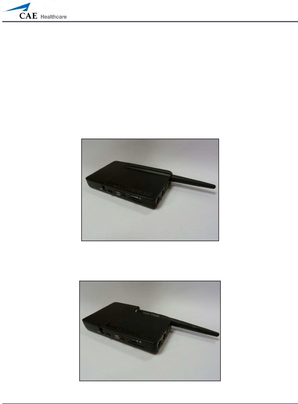
B-3
Appendix B – Wireless Voice Link
Wireless Voice Link Devices
There are two unique devices that make up a WVL pair: the handset device and the base
station device. The base station device is located inside the simulator, while the handset
device is battery powered and carried by the user. The handset transmits voice input through
a microphone to the base station receiver, where it is transmitted to the speakers in the
simulator’s head. The two dierent devices can be identied by their cases.
The handset device has a cover that extends over the length of the antenna.
Figure 1: WVL Handset
The base station device antenna is almost fully exposed.
Figure 2: WVL Base Station
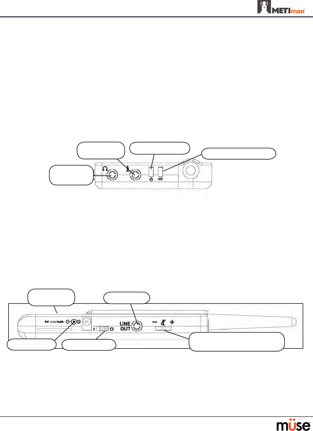
B-4
Appendix B – Wireless Voice Link
Physical Features
The following features are located on the top of the WVL devices:
Headphone jack: • Used to plug in headphones or an iPhone compatible headphone/
microphone combination
Microphone jack: • Used to plug in a standalone microphone
Red power light: • Indicates when the unit is powered on by blinking. Also indicates when
the Mute button is activated by solidly staying on.
Green connection light: • Indicates an RF link connection between the handset and base
station by blinking.
•
Figure 3: WVL Front View
The following features are located on the side of the WVL devices:
Battery compartment: • Houses two AAA batteries and the DIP switch.
DC power jack:• Accommodates a 5VDC/0.2A power source.
ON/OFF switch: • Turns WVL handset power on or o.
Line out jack: • Connects the WVL to the simulator’s audio amplier.
Volume/mute dial: • Controls microphone gain and microphone mute on the handset. See
Special Handset Settings on page B-9
Figure 4: WVL Side View
On the WVL handset, the volume/mute dial controls the microphone volume or mutes the
microphone. See Special Handset Settings on page B-9.
On the WVL base station, the dial serves as the volume control for the speakers inside the
simulator. Moving the dial toward the plus sign increases the volume. Moving the dial toward
the minus sign decreases the volume and setting. On the handset, pressing straight down on
the volume dial in the center mutes the microphone.
Microphone
jack
Red power light
Headphone
jack
Green connection light
DC Power
Line out
Volume/mute dial (Handset)
Volume/mute dial (Base Station)
ON/OFF switch
Battery
compartment
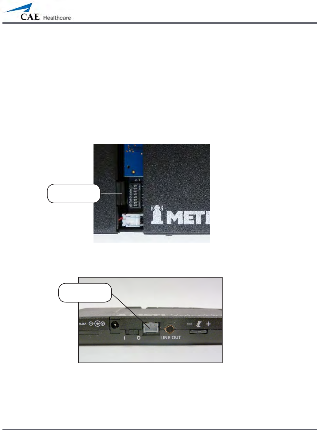
B-5
Appendix B – Wireless Voice Link
Preparing the Base Station in the Simulator
When using the base station in the simulator, ensure the batteries are removed and the
following items are attached:
Power cable
•
Line out cable•
Serial Connector•
The DIP switch is located in the battery compartment of the base station (Figure 5: DIP Switch
Settings).
Figure 5: Dip Switch Settings
The serial connector is located on the side of the base station (Figure 6: Serial Connector).
Figure 6: Serial Connector on base station
DIP Switch
Settings
Serial
Connector
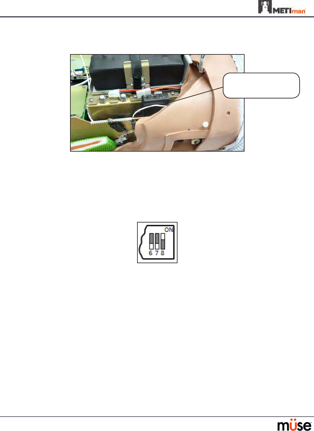
B-6
Appendix B – Wireless Voice Link
The base station should come already connected and installed inside the METIman.
Figure 7: Base Station in METIman
To prepare the base station:
Set the base station DIP switch positions 6 and 7 to OFF, and 8 to ON.
3.
Turn the power o and on using the power switch on the outside of the base 4.
station to ensure the DIP switch changes take eect.
Leave the power switch on the outside of the base station in the on position.
5.
Figure 8: DIP Switch Settings for the Base Station
NOTE: Since the base station receives power from the simulator, the power switch on the
outside of the base station must remain in the ON position. Use this power switch to refresh
DIP switch settings. Do not turn the simulator o and on to refresh the DIP switch settings.
Base Station
Connected and Installed
in METIman

B-7
Appendix B – Wireless Voice Link
Preparing the Handset for Use
To prepare the handset for use:
Insert two AAA batteries into the battery compartment.
1.
Set the handset DIP switch positions 6 and 7 to OFF and position 8 to ON. 2.
Turn the power switch o and back on to ensure the DIP switch changes take 3.
eect.
Figure 9: DIP Switch Settings for the Handset
While DIP switch positions 6 through 8 aect the handset and base station settings, DIP switch
positions 1 through 5 are used to set the radio frequency channel used for communication
between the handset and the base station.
Selecting the Radio Frequency Channel
There are two ways to congure the radio frequency (RF) channel spacing. The rst
method reduces channel-to-channel interference, but allows only 12 channels to operate
simultaneously in the same vicinity. The second method increases the number of channels that
can be used simultaneously to 20 channels. However, this method diminishes the channel-to-
channel noise immunity.
All of the WVL pairs in the same vicinity must use channels from RF Channel Group 1 or RF
Channel Group 2, and channels must belong to the same group. The DIP switch determines the
initial communication frequencies that the WVL pair use to communicate when the power of
the base station and handset is rst turned on. If there is too much interference at the initial
channel, the WVL pair changes frequency automatically and continues operating. The WVL
pair repeats this process automatically as needed and changes frequencies when interference
is too high.
Multiple WVL pairs can be set to the same initial frequency. However, setting dierent initial
frequencies helps the WVL pairs quickly nd a stable operating frequency.
For example, if there are 12 or fewer simulators in the same vicinity, set all of the WVL pairs to
use channel 0 of RF Channel Group 1. To give unique initial RF frequencies, assign each WVL
pair to its own RF channel with the settings found in CH 0 through CH 11.
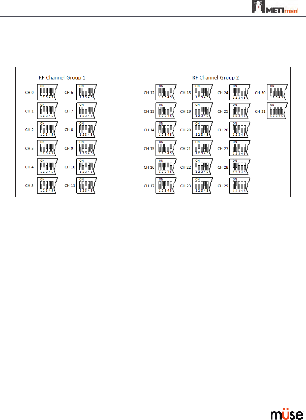
B-8
Appendix B – Wireless Voice Link
If you have 13 to 20 simulators in the same vicinity, set all of the WVL pairs to use channel 12 or
RF Channel Group 2. To give unique initial RF frequencies, assign each WVL pair to its own RF
channel with the settings found in CH 12 through CH 31.
Figure 10: RF Channel Selection Methods
For a complete list of the initial frequencies associated with the RF Channels, see RF Channel
Initial Operating Frequencies on page B-12.
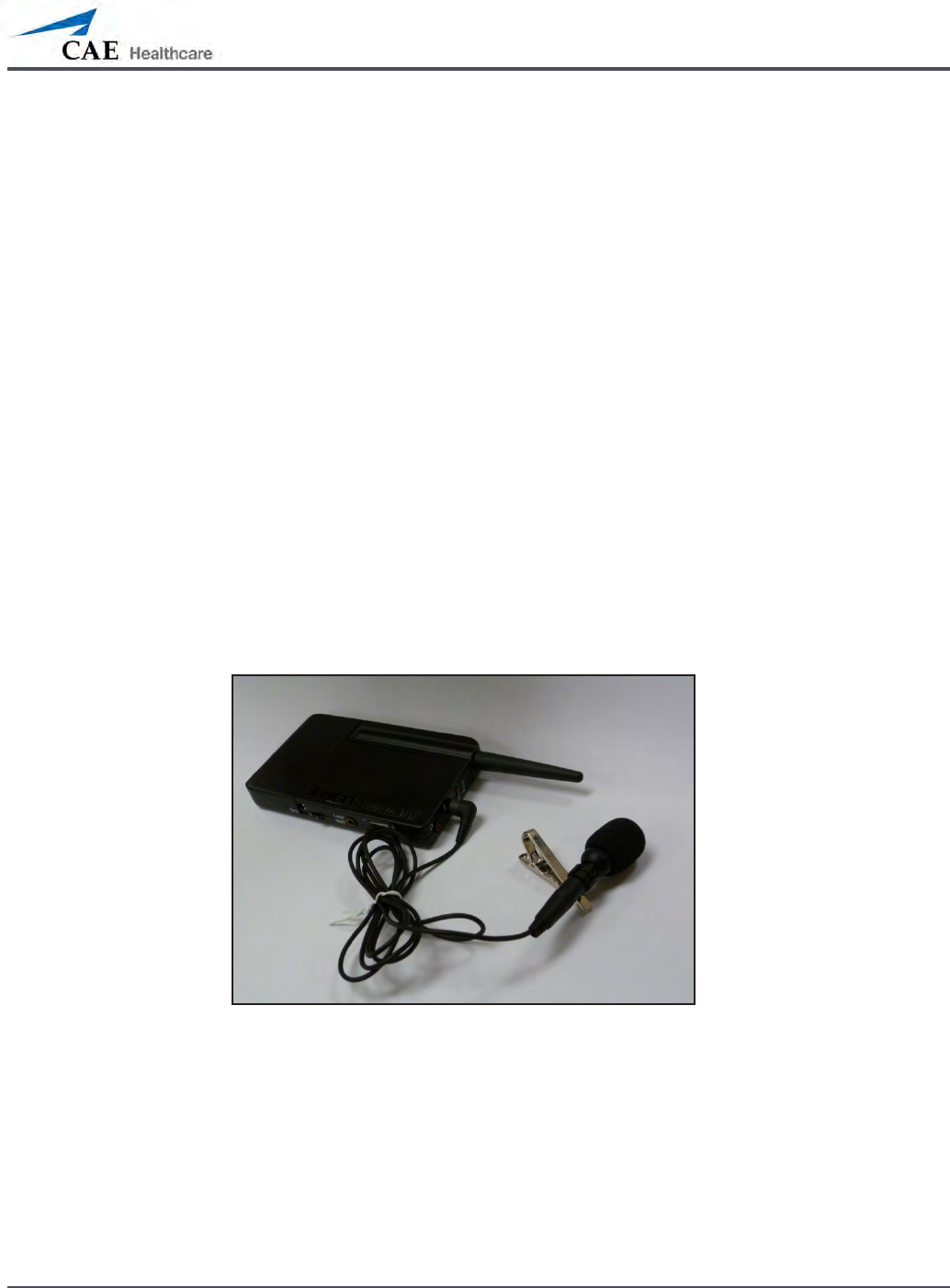
B-9
Appendix B – Wireless Voice Link
Powering Up the WVL Pair
To power up the WVL pair:
Power on the base station by turning on the simulator. The base station power switch is in the on
position by default.
Power on the handset by setting the power switch to the on position.
The red power light on each unit blinks when the unit is on. Once both units are powered on and
communicating with each other, the green connection light ashes once every second.
If the green connection light fails to blink, ensure both units are set to the same RF channel.
See Selecting the Radio Frequency Channel on page B-6. If you make changes to the DIP switch
settings, toggle the power switches of the handset and base station o and back on to ensure the
changes takes eect.
Using the iPhone/Standalone Microphone
DIP switch position 6 on the handset determines if the iPhone microphone input or the
standalone microphone input is enabled. When DIP switch position 6 is set to the OFF position,
the standalone microphone jack is enabled for the standalone microphone, provided by CAE
Healthcare.
Figure 11: Handset and CAE Healthcare-provided Microphone
To use a microphone compatible with an iPhone (three-pole jack), set DIP switch position 6 to
ON. Please note that an iPhone-compatible microphone is not provided as part of the product
package. Any microphone with a common 3.5 mm input jack can be used with the handset when
DIP switch position 6 is set to ON.
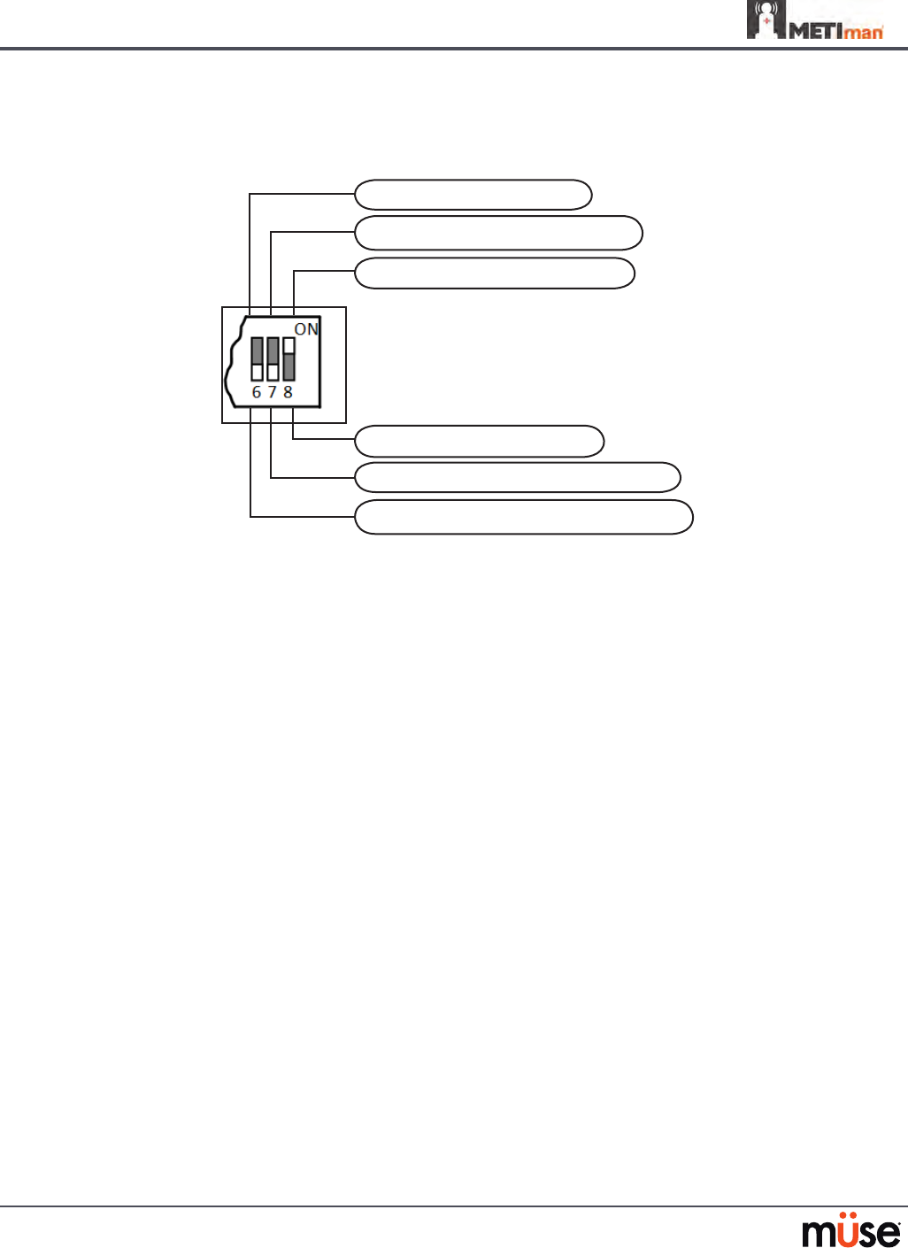
B-10
Appendix B – Wireless Voice Link
Special Handset Settings
Advanced settings for the handset DIP switch are available.
Noise reduction enable (default)
Base station volume control enable
Microphone gain control enable (default)
Noise reduction disable
Standalone microphone enable (default)
iPhone microphone enable
Figure 12: Advanced DIP Switch Settings
DIP switch settings are only refreshed when the handset is powered on. To ensure the DIP
switch changes take eect, turn the power o and back on after making changes.
To enable noise reduction and minimize background noise in high ambient noise
environments, place the position 8 DIP switch in the ON position.
Battery Capacity Indicator
The red power light ashes one time every second when the battery capacity is good. When
the battery capacity is nearly depleted, the red power LED ashes twice in quick succession
every second. This indicates the batteries need to be replaced.
To get the most battery life out of the handset, the handset should be powered down when it
is not in use.

B-11
Appendix B – Wireless Voice Link
Troubleshooting
CAE Healthcare Customer Service is available to help with iStan problems, should they
arise. However, sometimes you can speed up the customer service process by performing
diagnostics before calling, and eliminating some problems on your own with the help of the
following instructions.
Power Problems
The red power light on the handset does not ash when power switch is turned on.
Check that the batteries are inserted correctly. Install a fresh set of batteries, if needed.
•
The red power light on my base station is not ashing when the simulator is powered on.
Check that the cables from the simulator are installed in the base station correctly.
•
Communication Problems
The simulator and handset are turned on, but the green connection light is not blinking.
Verify that DIP switch positions 1 through 5 are all set to OFF, which is the default position
•
set in the simulator base station and handset at the factory. If you have modied this
setting, verify positions 1 through 5 on the handset and the simulator base station are
the same.
Be sure to turn the power o and back on for the changes to take eect on both the
•
handset and the base station. Check if the green connection light is ashing after turning
the power o and back on each time to see if communication has been established
between the base station and the handset.
I’m experiencing static or dropouts in the simulator audio output.
Reduce the range between the base station and the handset. Most likely, the handset
•
is out of range of the base station, or there may be too many obstacles (walls, windows,
doors) between the handset and the simulator.
Audio Problems
The sound output from the simulator is low when using a microphone on my lapel.
Increase the microphone gain on the handset by moving the dial towards the plus sign.
•
DIP switch 7 must be in the OFF position for this to work.
I’m hearing feedback from the microphone when I am close to the simulator.
Decrease the microphone gain on the handset by moving the dial towards the minus
•
sign. DIP switch 7 must be in the OFF position for this to work.

B-12
Appendix B – Wireless Voice Link
The sound output from the simulator is too high or too low.
The volume level is congured at the factory for optimal performance. However, if you •
want to adjust the volume level of the base station (located inside the simulator), set the
handset DIP switch 7 to ON. Remember to turn the handset power o and on after each
DIP-switch change. After this step is complete, you will be able to adjust the volume level
of the base station by adjusting the handset volume dial.
The sound output from the simulator is noisy when the speaker is not speaking.
You can use the noise reduction feature by setting the handset DIP switch position 8 to
•
ON.
The simulator voice output is cut o when the speaker is speaking quietly.
In this case, there are three possible options:
•
- Attempt to talk louder
- Increase the microphone gain
- Disable the noise reduction feature by setting the handset DIP switch 8 to OFF.

B-13
Appendix B – Wireless Voice Link
RF Channel Initial Operating Frequencies
RF Channel Frequency 1 (GHz) Frequency 2 (GHz)
0 2.402 2.480
1 2.405 2.477
2 2.408 2.474
3 2.411 2.471
4 2.414 2.468
5 2.417 2.465
6 2.420 2.462
7 2.423 2.459
8 2.426 2.456
9 2.429 2.453
10 2.432 2.450
11 2.435 2.447
12 2.402 2.480
13 2.404 2.478
14 2.406 2.476
15 2.408 2.474
16 2.410 2.472
17 2.412 2.470
18 2.414 2.468
19 2.416 2.466
20 2.418 2.464
21 2.420 2.462
22 2.422 2.460
23 2.424 2.458
24 2.426 2.456
25 2.428 2.454
26 2.430 2.452
27 2.432 2.450
28 2.434 2.448
29 2.436 2.446
30 2.438 2.444
31 2.440 2.442

B-14
Appendix B – Wireless Voice Link
Specications
Frequency of operation: 2.400 – 2.4835 GHz
Wireless range: 100 ft clear line of sight
RF power output: 0dBm
Batteries: 2 AAA Alkaline, NiCd, NiMH, Lithium
Handset battery life with base station on: 25 hours with alkaline batteries
Handset battery life with base station o: 100 hours with alkaline batteries
DC voltage input: 5 VDC, 0.2A
Line out jack: 3.5 mm
Headphone/iPhone jack: 3.5 mm
Standalone microphone jack: 3.5 mm
Mechanical dimensions with antenna: 6.17” x 2.52” x 0.65”
Mechanical dimensions without antenna: 4.2” x 2.52” x 0.65”

For more information about CAE Healthcare products, contact your regional sales manager
or the CAE Healthcare distributor in your country, or visit caehealthcare.com.
Tel +1 941-377-5562 or 866-233-6384
For customer service, please contact CAE Healthcare.
Customer Service Headquarters - United States and Latin America
Monday - Friday from 7:00 a.m. to 6:00 p.m. ET
Phone 1-866-462-7920
Email: customerservice@caehealthcare.com
Customer Service - Canada
Monday - Friday from 8:00 a.m. to 5:00 p.m. ET
Phone 1-877-223-6273
Email: can.service@caehealthcare.com
Customer Service - Europe, Middle East, Africa, India, Asia and Australia
Monday - Friday from 8:00 a.m. to 5:00 p.m. CET
Phone +49 (0) 6131 4950354
Email: international.service@caehealthcare.com
Customer Service - United Kingdom and Ireland
Monday - Friday from 9:00 a.m. to 5:00 p.m. GMT
Phone +44 (0)800-917-1851
Email: uk.service@caehealthcare.com
©2012 CAE Healthcare
165k360110 v.4.1
caehealthcare.com