CAEN RFID srl CAENRFID001 Low Power Communication Device Transmitter User Manual A828US rev2 FCC
CAEN RFID srl Low Power Communication Device Transmitter A828US rev2 FCC
Users Manual

Technical
Information
Manual
Mod. A828US
18 December 2006
Revision n. 2
OEM UHF COMPACT
READER (FCC PART 15)
NPO:
00107/05:828US.MUTx/02

Document type: Title: Revision date: Revision:
User's Manual (MUT) Mod. A828US OEM UHF compact reader 18/12/2006 2
INDEX
1. INTRODUCTION................................................................................................................................................3
2. MOD. A828US TECHNICAL SPECIFICATIONS ..........................................................................................4
2.1. MOD. A828US TECHNICAL SPECIFICATIONS TABLE.......................................................................................4
2.2. EXTERNAL CONNECTIONS................................................................................................................................4
2.2.1. MOLEX Connector Specifications..........................................................................................................5
2.2.2. Regulatory Compliance..........................................................................................................................6
LIST OF FIGURES
FIG. 1.1: MOD. A828US OEM UHF COMPACT READER (FCC PART 15)................................................................3
FIG. 2.1: MOD. A828US TECHNICAL DRAWINGS ....................................................................................................5
FIG. 2.2: STATUS BLOCK DIAGRAM ........................................................................................................................6
LIST OF TABLES
TABLE 2.1: MOD. A828US TECHNICAL SPECIFICATIONS .......................................................................................4
TABLE 2.2: MOLEX CONNECTOR ELECTRICAL SPECIFICATIONS ............................................................................5
NPO: Filename: Number of pages: Page:
00107/05:828US.MUTx/02 A828US_REV2_FCC.DOC 6 2
Document type: Title: Revision date: Revision:
User's Manual (MUT) Mod. A828US OEM UHF compact reader 18/12/2006 2
1. Introduction
The A828US OEM UHF compact reader (FCC part 15), is a CAEN multi protocol OEM
compact module for integration into barcode printers, printer applicators, handheld
computers and PDAs, devices requiring UHF tag programming and reading.
The A828US is fully compliant to the US telecommunication regulation FCC part 15 (902-
928 MHz).
Currently the A828EU Module supports the ISO18000-6 B, the Philips UCODE EPC 1.19
and EPC Class1 Gen2 protocols, other future UHF protocols will be available by firmware
upgrade.
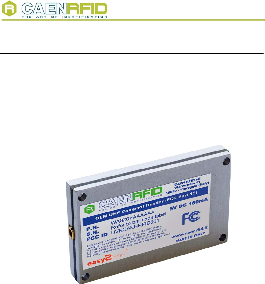
Fig. 1.1: Mod. A828US OEM UHF compact reader (FCC part 15)
NPO: Filename: Number of pages: Page:
00107/05:828US.MUTx/02 A828US_REV2_FCC.DOC 6 3
Document type: Title: Revision date: Revision:
User's Manual (MUT) Mod. A828US OEM UHF compact reader 18/12/2006 2
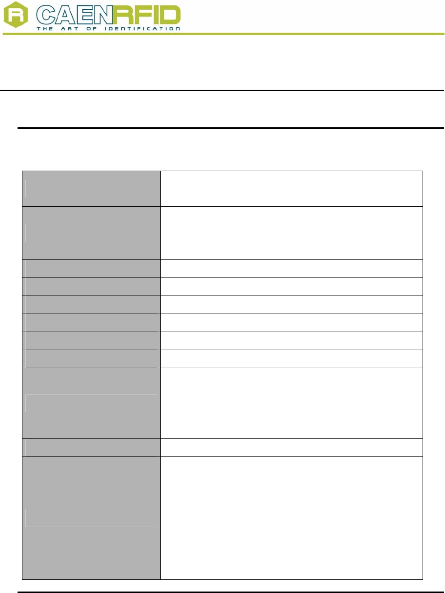
2. Mod. A828US Technical Specifications
2.1. Mod. A828US Technical Specifications Table
Table 2.1: Mod. A828US Technical Specifications
Dimensions 37 x 60 x 6.6 mm3
(1.46 x 2,36 x 0.26 inches3)
Electrical Power
180 mA @ 5 V (TX/RX mode)
80 mA @ 5 V (idle mode)
200 µA @ 5 V (stby mode)
Operating Temperature -20 °C to 60 °C
Frequency 912.500÷917.400 MHz (FCC part 15)
RF Power 50 mW @ 5 V (17 dBm)
Antenna 1 external antenna MMCX connector
Frequency Tolerance ±10 ppm over the entire temperature range
Number of channels 50 hopping channels (compliant to FCC part 15)
Standard Compliance
ISO 18000-6B
Philips UCODE EPC 1.19
EPC C1G2
EPC C1G1 (via firmware upgrade)
Digital I/O Five I/O lines 3.3V out, 5V tolerant
UART Serial Port
Baudrate: 115200
Databits: 8
Stopbits: 1
Parity: none
Flow control: none
3.3 V out, 5 V tolerant
96÷115 kbit/s data rate (settable)
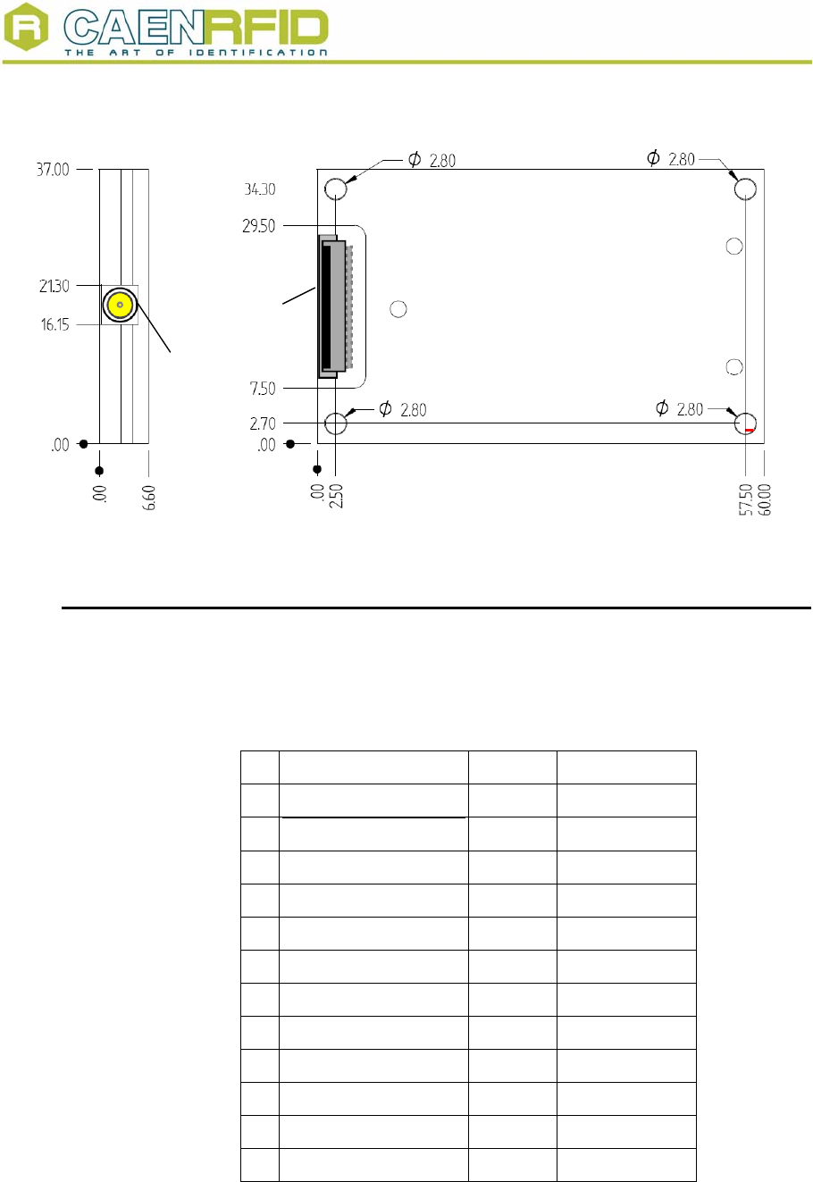
2.2. External connections
The location of the connectors is shown in Fig. 2.1. Their mechanical specifications are
listed here below:
Antenna Port: RF Coax Connector Huber+Suhner type 82MMCX-S50-0-2/111_K (to be
used with Huber+Suhner type 11MMCX-50-1-1/111_O)
MOLEX Connector: PCB Headers Molex type 53261-1290
(to be used with Molex Type 51021-1200 + 12pcs crimp terminal type 50058-8100)
NPO: Filename: Number of pages: Page:
00107/05:828US.MUTx/02 A828US_REV2_FCC.DOC 6 4
Document type: Title: Revision date: Revision:
User's Manual (MUT) Mod. A828US OEM UHF compact reader 18/12/2006 2
A
ntenna
Molex
Connector
Fig. 2.1: Mod. A828US technical drawings
2.2.1. MOLEX Connector Specifications
The compact reader A828US external connector is a SMD, 12 poles, 1.27 pitch
connector whose pinout is shown in table below.
Table 2.2: MOLEX Connector electrical specifications
Pin Function Direction Duration (min.)
1 Power Line (+5V) - -
2 /RESET(active low) IN 200 ns
3 GPIO0 IN/OUT -
4 GPIO1 IN/OUT -
5 GPIO2 IN/OUT -
6 GPIO3 IN/OUT -
7 GPI/O 4 - /TAG ID IN/OUT -
8 /WAKEUP(active low) IN 200 ns
9 RXD IN -
10 TXD OUT -
11 GND - -
12 GND - -
NPO: Filename: Number of pages: Page:
00107/05:828US.MUTx/02 A828US_REV2_FCC.DOC 6 5
Document type: Title: Revision date: Revision:
User's Manual (MUT) Mod. A828US OEM UHF compact reader 18/12/2006 2
The GPIO0-GPIO4 pin are 5 general purpose bidirectional pins, their default direction (or
after a Reset) is Out; GPIO4 works also as Identify Tag signal. the Wakeup pin (active
low) must be used when the A828US board is put into power down mode.
The RXD/TXD pins are used to communicate with the A828US board via UART port; to
establish a link with the device you must configure your COM port as follows:
1. Baud rate : 115200
2. Parity : None
3. Data bits : 8
4. Stop bits : 1
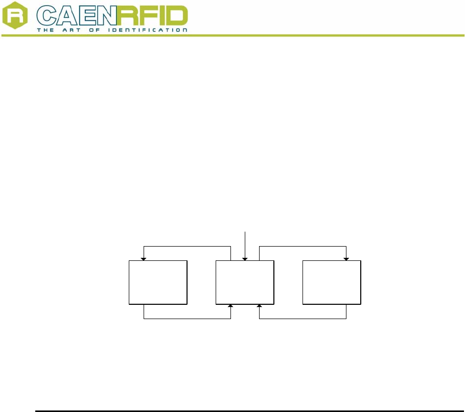
The following diagram shows the A828US status:
STBY IDLE TX/RX
RESET/POWER ON
STBY COMMAND RF COMMAND
WAKE UP SIGNAL COMMAND COMPLETE
Fig. 2.2: Status block diagram
2.2.2. Regulatory Compliance
This equipment has been tested and found to comply with Part 15 of the FCC Rules.
NOTE:
(a) Any changes or modification not approved by CAEN RFID could void the user’s
authority to operate the equipment.
(b) The A828US Module, which is rated at 50 mW output, cannot use an antenna with
more than 16 dBi of gain. Use of any other antenna with a gain greater than 16 dBi may
void the user’s authority to operate the equipment.
NPO: Filename: Number of pages: Page:
00107/05:828US.MUTx/02 A828US_REV2_FCC.DOC 6 6