CAEN RFID srl CAENRFID016 A528B - Muon - Compact Embedded UHF RFID Reader User Manual R1230CB
CAEN RFID srl A528B - Muon - Compact Embedded UHF RFID Reader R1230CB
UserManual.wiki
>
CAEN RFID srl
>
CAENRFID016 User Manual
User Manual
Navigation menu
Upload a User Manual
Namespaces
Wiki Guide
HTML
PDF
Info
Views
User Manual
Discussion / Help
Navigation

![Scope of Manual The goal of this manual is to provide the basic information to work with the A528B Muon Compact Embedded UHF RFID Reader. Change Document Record Date Revision Changes Pages 20 Feb 2013 00 Preliminary release - 19 Mar 2013 01 Added § EC Declaration of Conformity 27, 28 21 Mar 2013 02 Modified Return link characteristics in the Tab. 2.1: Muon A528B Technical Specifications 10 30 Apr 2013 03 Added Federal Communications Commission (FCC) Notice (Preliminary) 3 Added FCC Compliance paragraph 27 Changed Tab. 2.1: Muon A528B Technical Specifications Table 10 27 May 2013 04 Modified FCC Compliance paragraph 27 Reference Document [RD1] EPCglobal: EPC Radio-Frequency Identity Protocols Class-1 Generation-2 UHF RFID Protocol for Communications at 860 MHz – 960 MHz, Version 1.1.0 (December 17, 2005). [RD2] G.S.D. s.r.l. - Report CE mark – A528B Muon Compact Embedded UHF RFID Reader. Test report n. 13122 Rev.00 - 12 March 2013. . CAEN RFID srl Via Vetraia, 11 55049 Viareggio (LU) - ITALY Tel. +39.0584.388.398 Fax +39.0584.388.959 info@caenrfid.com www.caenrfid.com © CAEN RFID srl – 2010 Disclaimer No part of this manual may be reproduced in any form or by any means, electronic, mechanical, recording, or otherwise, without the prior written permission of CAEN RFID. The information contained herein has been carefully checked and is believed to be accurate; however, no responsibility is assumed for inaccuracies. CAEN RFID reserves the right to modify its products specifications without giving any notice; for up to date information please visit www.caenrfid.com.](https://usermanual.wiki/CAEN-RFID-srl/CAENRFID016/User-Guide-1996231-Page-2.png)


![Muon A528B - A528ADAT - Technical Information Manual 10 Technical Specifications Table Frequency Range 902÷928 MHz (FCC part 15.247) 865.600÷867.600 MHz (ETSI EN 302 208 v1.4.1) RF Power Programmable in 8 levels from 10dBm to 27dBm Output Power Accuracy +/- 1dB Antenna VSWR Requirement <2:1 or better for optimum performances Antenna Connector Nr. 1 MMCX jack Frequency Tolerance ±10 ppm over the entire temperature range Number of Channels 4 channels (compliant to ETSI EN 302 208 v1.4.1) 50 hopping channels (compliant to FCC part 15.247) Standard Compliance EPC C1G2 [RD1] Forward link characteristics DSB-ASK 40kBit/s; PR-ASK 40kBit/s; DSB-ASK 160kBit/s (FCC only) Return link characteristics FM0 40kbit/s Miller encoding (M=4;LF=250kHz) Miller encoding (M=4;LF=300kHz) FM0 400kbit/s (FCC only) Digital I/O Four I/O lines 3.3V out @ 3mA; 5V tolerant Connectivity UART Serial Port: Baudrate: up to 115200 Databits: 8 Stopbits: 1 Parity: none Flow control: none 3.3V level USB Device Port: One USB 2.0 Full Speed (12 Mbits per second) device port. Dimensions (W)42 x (L)60 x (H)6.3 mm3 (1.65 x 2.36 x 0.25 inch3) DC Power 4.75V ÷ 5.25V ripple and noise < 100mVpp ripple frequency > 100kHz Power Consumption 1A peak @ 5 V (TX/RX mode) 230 mA @ 5 V (idle mode) Operating Temperature -20 °C to 60 °C Weight 18 g Tab. 2.1: Muon A528B Technical Specifications Warning: please set up the correct RF regulation of your country following the CAEN RFID instructions.](https://usermanual.wiki/CAEN-RFID-srl/CAENRFID016/User-Guide-1996231-Page-10.png)

![Muon A528B - A528ADAT - Technical Information Manual 12 TST_RECOVERY pin is reserved and shall be used only to perform the microcontroller recovery procedure during which it must be forced at high level (3.3V or 5V). The RXD/TXD pins are used to communicate with the A528 board via UART port; to establish a link with the device you must configure your COM port as follows2: Baud rate: 115200 Parity: None Data bits: 8 Stop bits: 1 Flow Control: none A528B Main connector electrical characteristics3 Pin name Pin No. Parameter Min Typ Max Unit +5V 1 Supply DC voltage 4.75 5.00 5.25 V Power supply requirements –Ripple Voltage 100 mVpp Power supply requirements - Ripple Frequency 100 kHz Supply DC current 0.23 1.0 A /RESET 2 VIL -0.3 1.0 V VIH 2.4 3.6 V Internal pull-up resistance 10 20 kΩ Pulse width 1 μs GPIO[0:3] 3, 4, 5, 6 VOL 0 0.4 V VOH 2.0 3.3 V Output current 3.0 mA VIL -0.3 0.8 V VIH 2.0 5.5 V Input current 1 μA TST-Recovery 7 VIH 2.0 5.5 V USB PUP 8 VIH 2.0 5.5 V RXD 9 VIL -0.3 0.8 V VIH 2.0 5.5 V Input current 1 μA TXD 10 VOL 0 0.4 V VOH 2.4 3.3 V Output current 1.5 mA GND 11,12 Tab. 2.3: Muon A528B Main Connector electrical characteristics 2 Since A528B RX/TX are TTL level signals, in order to connect it with a PC, a TTL/RS232 translator shall be used. 3 Exceeding maximum values reported in the table may cause permanent damage to the model.](https://usermanual.wiki/CAEN-RFID-srl/CAENRFID016/User-Guide-1996231-Page-12.png)


![Muon A528B - A528ADAT - Technical Information Manual 17 Reader - Tag Link Profiles A528B reader supports different modulation and return link profiles according to EPC Class1 Gen2 protocol [RD1]. In the following table are reported all profiles that have been tested for the compliance with ETSI and FCC regulations. Link profile # Regulation Modulation Return Link 0 ETSI - FCC DSB–ASK; f=40kHz FM0; f = 40kHz 1 ETSI - FCC PR-ASK; f=40kHz Miller (M=4); f = 250kHz 2 ETSI PR-ASK; f=40kHz Miller (M=4); f = 300kHz 3 FCC DSB-ASK; f=160kHz FM0; f = 400kHz 4 FCC PR-ASK; f=40kHz Miller (M=2); f = 250kHz Tab. 2.8: Muon A528B Reader to Tag Link Profiles Host communication interfaces A528B reader allows the user to manage host communication through the CAEN communication protocol6: the host-reader interface is serial and A528B is fully compatible with all the CAEN Demos and libraries included in the Easy2Read SDK. Only if the use of USB interface is necessary, it is available the Intel communication protocol: the host-reader interface is USB. Using the Intel protocol, serial interface has debug purpose only. Intel communication protocol is not supported by CAEN RFID. The default setting of the A528B reader is the Serial/CAEN choice, in order to switch to the INTEL protocol on USB interface you shall follow the steps described below: 1. Connect to the reader, using a RS232 cable7, with the Hyperterminal (or with any other terminal emulation application) with the following settings: baud rate: 115200 data bits: 8 parity: none stop bits: 1 Flow control: None 2. Type quickly the word CAEN (in capital letters) in the hyperterminal window. 3. Type chgprot in the hyperterminal window. 4. Select the USB interface and INTEL protocol options when prompted. After a reset the reader will reply to the INTEL commands. In order to switch from the INTEL protocol on USB interface to the Serial/CAEN protocol you shall follow the steps described below: 1. Connect to the reader, using a RS232 cable8, with the hyperterminal (or with any other terminal emulation application) with the following settings: baud rate: 115200 data bits: 8 parity: none stop bits: 1 Flow control: None 2. Stop the boot process pressing the spacebar within 6 seconds from the power on. 3. Type chgprot in the hyperterminal window. 4. Select the Serial interface and CAEN protocol options when prompted. After a reset the reader will reply to the CAEN commands. 6 Serial / CAEN procotol is implemented starting from FW release 1.1.5. 7 Assuming to use A528 adapter board and a PC as host. 8 Assuming to use A528 adapter board and a PC as host.](https://usermanual.wiki/CAEN-RFID-srl/CAENRFID016/User-Guide-1996231-Page-17.png)


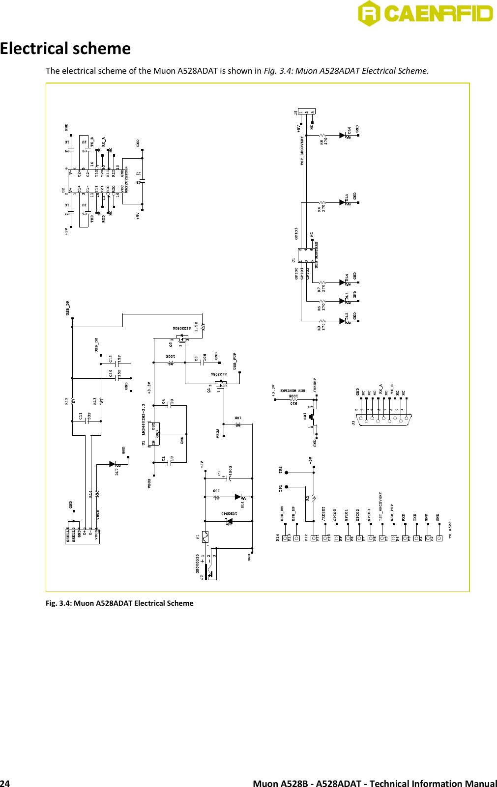
![Muon A528B - A528ADAT - Technical Information Manual 21 Technical Specifications Table Digital I/O Four I/O lines 3.3 V out @ 3mA, 5 V tolerant USB Port USB B female connector USB 2.0 device It appears as USB A528B device; drivers for Windows XP, Windows CE 5.0, Linux 4 and greater RS232 Port Baudrate: 115200 Databits: 8 Stopbits: 1 Parity: none Flow control: none 9.6÷115 kbit/s data rate (settable) LED display RED: Power GREEN: GPIO[0..3], USB connection YELLOW: RECOVERY procedure Dimensions (W)81 x (L)76 x (H)28 mm3 (3.2 x 3.0 x 1.1 inch3) Electrical Power DC Voltage 5V +/-5% Current consumption: 1A max. Operating Temperature -20 °C to +60 °C Tab. 3.1: Muon A528ADAT Technical Specifications Connection Diagram The following block diagram shows how to connect the Muon A528B with the PC host via the Muon A528ADAT service board. The board equipped with A528B reader shall be powered by external 5V 1A DC adapter. In order to ensure the correct operation of the reader the power supply shall not enter in burst mode (switching frequency less then 100kHz) when A528B reader is in idle mode (supply current about 0.2A). As a rule of thumb the power adapter shall have a maximum current rating from 1A to 1.5A. Fig. 3.1: Muon A528ADAT Connection Diagram](https://usermanual.wiki/CAEN-RFID-srl/CAENRFID016/User-Guide-1996231-Page-21.png)


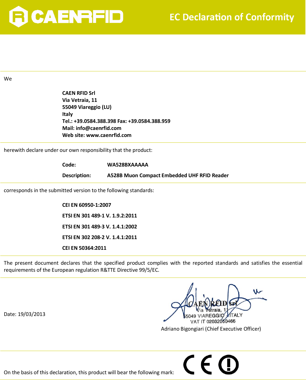
![Muon A528B - A528ADAT - Technical Information Manual 27 FCC Compliance This equipment has been tested and found to comply with Part 15 of the FCC Rules. NOTE: a. Any changes or modification not approved by CAEN RFID could void the user’s authority to operate the equipment. b. The Muon A528B Module, which is rated at 500 mW output, is approved for operation with the CAENRFID antenna Mod. WANTENNAX010 (Linear polarized 3dbi gain PIFA antenna for portable and desktop systems - 915 MHz). Use of other than the approved antenna with this unit may result in harmful interference with other users, and cause the unit to fail to meet regulatory requirements. The maximum allowed antenna gain to be used with A528B module is 3dBi. c. This transmitter module is authorized to be used in other devices only by OEM integrators under the following conditions: 1. The RFID Module antenna shall have a separation distance of at least 20 cm from all persons 2. The transmitter module must not be co-located with any other antenna or transmitter d. In case that the two conditions above are met, further transmitter testing will not be necessary. However, the OEM integrator is still responsible for testing the end-product for any additional compliance requirements required with this module installed (for example, digital device emissions, PC peripheral requirements, etc.). In the event that these conditions can not be met (for certain configurations or co-location with another transmitter), then the FCC authorization is no longer considered valid and the FCC ID can not be used on the final product. In such case the OEM integrator will be responsible for re-evaluating the end product (including the transmitter) and obtaining a separate FCC authorization. e. If the FCC ID is not visible when the module is installed inside another device, the OEM integrator shall apply a label in a visible area on his product with the following statement: Contains Transmitter Module FCC ID: UVECAENRFID016 or Contains FCC ID: UVECAENRFID016 f. The OEM integrator has to be aware not to provide information to the end user regarding how to install or remove this RF module or change RF related parameters in the user manual of the end product. CE Compliance Reference standard: CEI EN 60950-1:2007 ETSI EN 301 489-1 V. 1.9.2:2011 ETSI EN 301 489-3 V. 1.4.1:2002 ETSI EN 302 208-2 V. 1.4.1:2011 CEI EN 50364:2011 Reference document: Test report n. 13122 [RD2]. See § EC Declaration of Conformity pag. 28 for the Muon A528B CE Compliance Certificate. RoHS EU Directive Muon A528B OEM UHF multiregional Compact Reader is compliant with the EU Directive 2002/95/EC on the Restriction of the Use of certain Hazardous Substances in Electrical and Electronic Equipment (RoHS). Warning: please set up the correct RF regulation of your country following the CAEN RFID instructions.](https://usermanual.wiki/CAEN-RFID-srl/CAENRFID016/User-Guide-1996231-Page-27.png)