CalAmp Wireless Networks 14071R2 Wireless broadband router User Manual gsm
CALAMP WIRELESS NETWORKS INC. Wireless broadband router gsm
UserManual.wiki
>
CalAmp Wireless Networks
>
14071R2 User Manual
>
user manual gsm
Contents
1.
user manual gsm
2.
user manual cdma
user manual gsm
Navigation menu
Upload a User Manual
Namespaces
Wiki Guide
HTML
PDF
Info
Views
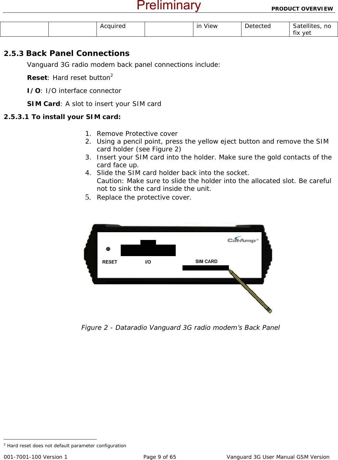
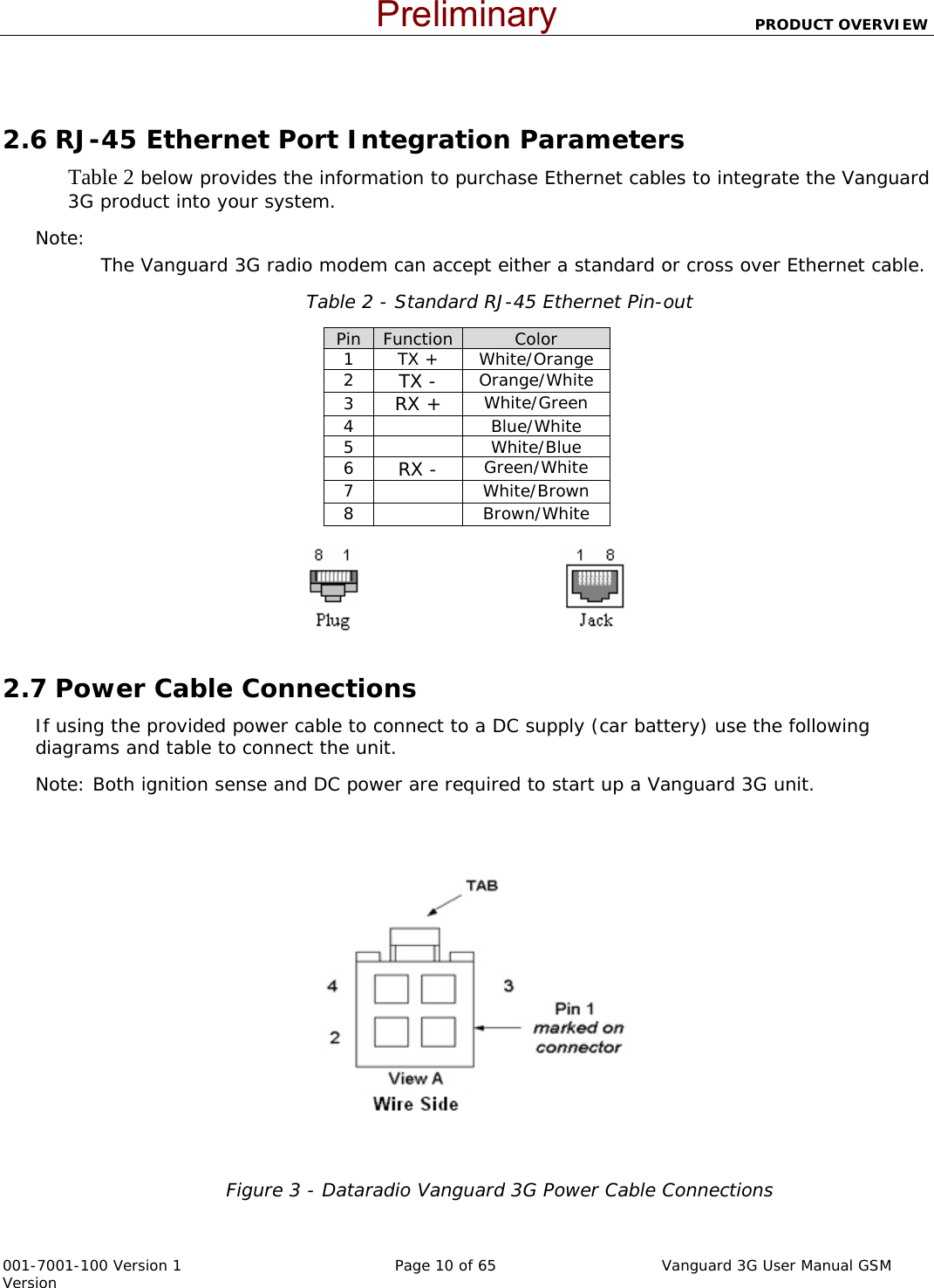
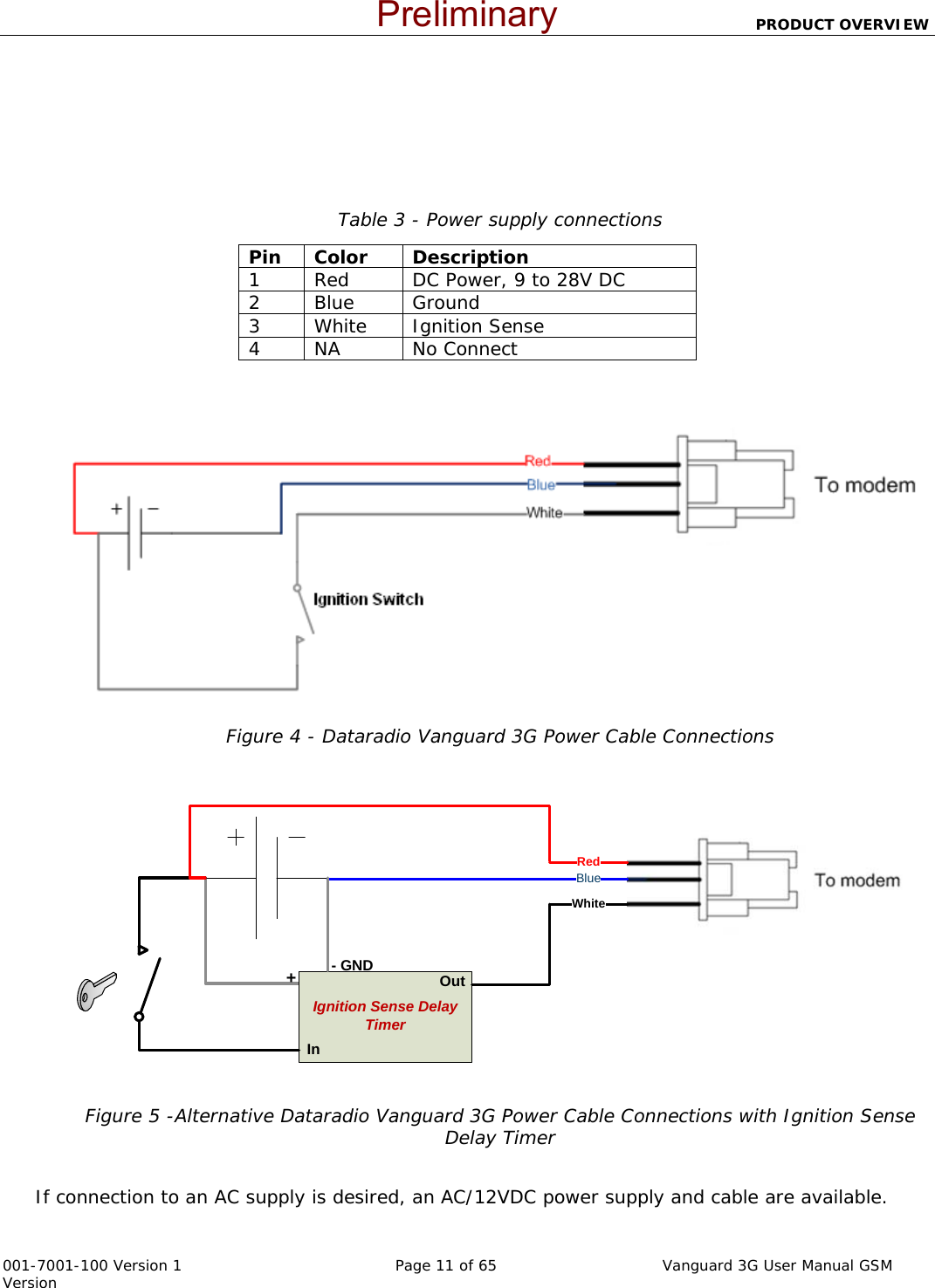
User Manual
Discussion / Help
Navigation