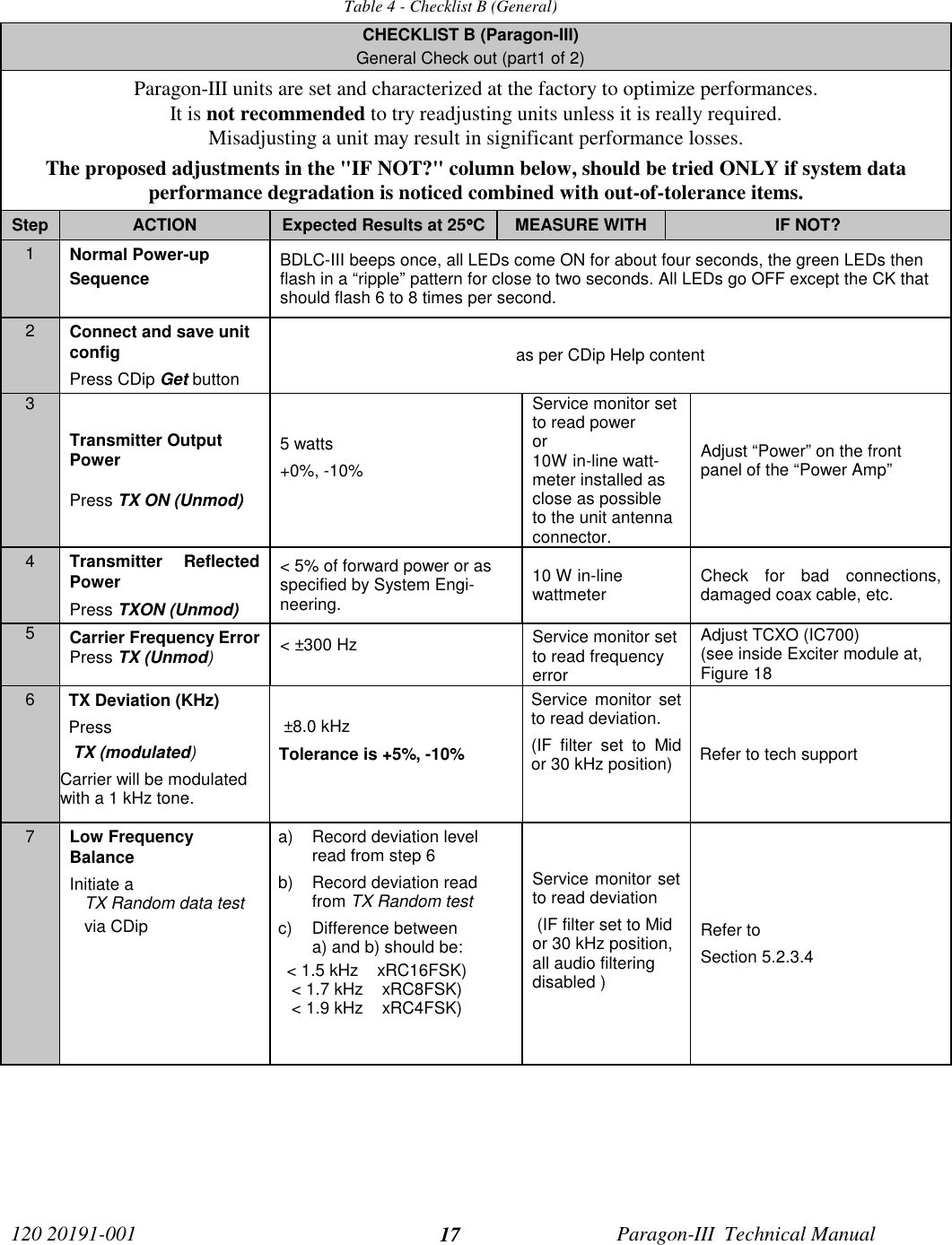
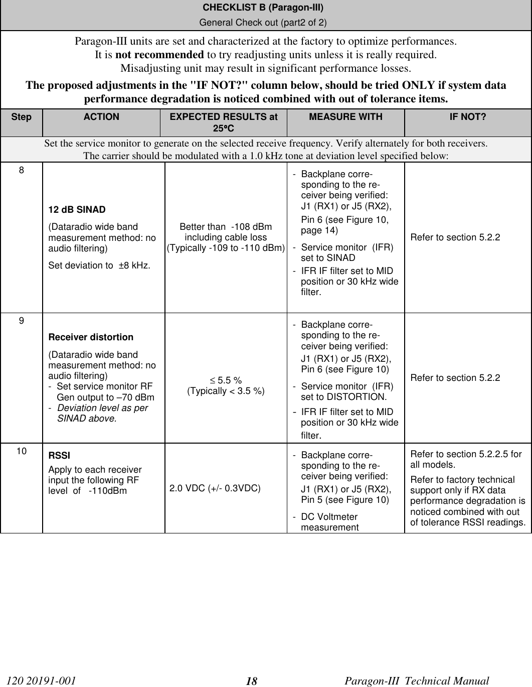
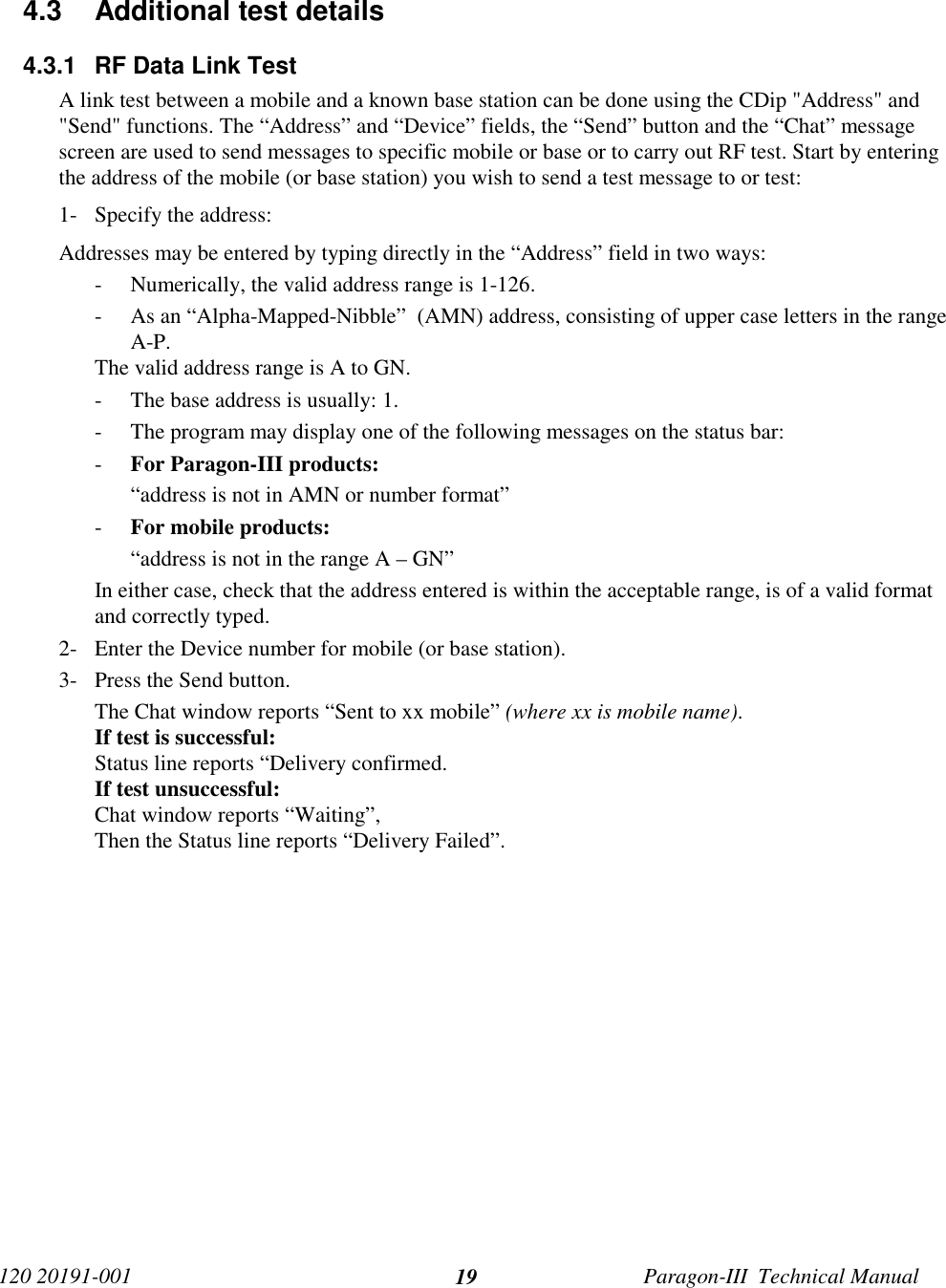
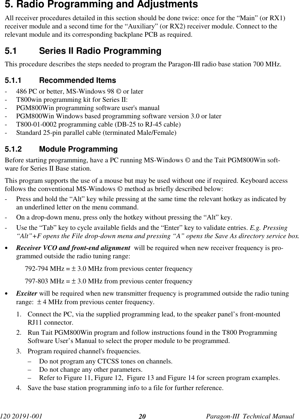
CalAmp Wireless Networks BDP3-T881 Paragon III User Manual annex G preliminary version

CALAMP WIRELESS NETWORKS INC. Paragon III annex G preliminary version

annex G preliminary version

Paragon-III(700 MHz)Data Base StationTechnical ManualVersion 0.01(preliminary)The entire contents of this manual and the Radio Installation Softwaredescribed in this manual are copyright 2004 by DATARADIO Inc.Copyright DATARADIO Inc.April 2004Part no.: 120 20191-001
120 20191-001 Paragon-III Technical Manualii1. PRODUCT OVERVIEW................................................................................................................................... 11.1 INTENDED AUDIENCE ....................................................................................................................................... 11.2 GENERAL DESCRIPTION .................................................................................................................................... 11.2.1 Features:................................................................................................................................................. 21.3 FACTORY TECHNICAL SUPPORT........................................................................................................................ 31.4 PRODUCT WARRANTY ...................................................................................................................................... 41.5 REPLACEMENT PARTS....................................................................................................................................... 41.5.1 Factory Repair........................................................................................................................................ 41.6 PACKAGING ...................................................................................................................................................... 42. INSTALLATION ............................................................................................................................................... 52.1 OVERVIEW........................................................................................................................................................ 52.2 LOCATION......................................................................................................................................................... 52.3 FRONT VIEW:.................................................................................................................................................... 52.4 REAR VIEWS:.................................................................................................................................................... 62.5 ELECTRICAL...................................................................................................................................................... 82.5.1 Paragon-III Assembly Power.................................................................................................................. 82.6 ANTENNA ....................................................................................................................................................... 102.6.1 Overview ............................................................................................................................................... 102.6.2 Cabling and Connection ....................................................................................................................... 102.7 COMPLETING THE PHYSICAL INSTALLATION.................................................................................................... 102.8 CHECKING OUT NORMAL OPERATION ............................................................................................................. 103. OPERATING DESCRIPTION ....................................................................................................................... 113.1 RADIO ASSEMBLY........................................................................................................................................... 11Receiver module................................................................................................................................................. 113.1.2 5W Transmitter module......................................................................................................................... 12BDLC-III module ............................................................................................................................................... 123.1.4 Speaker panel........................................................................................................................................ 133.1.5 Dual Power Supply module................................................................................................................... 133.1.6 Radio Backplane Assembly ................................................................................................................... 144. TROUBLE-SHOOTING AND TESTING ..................................................................................................... 154.1 EQUIPMENT REQUIRED ................................................................................................................................... 154.2 RECOMMENDED CHECKS................................................................................................................................154.3 ADDITIONAL TEST DETAILS ............................................................................................................................. 194.3.1 RF Data Link Test................................................................................................................................. 195. RADIO PROGRAMMING AND ADJUSTMENTS..................................................................................... 205.1 SERIES II RADIO PROGRAMMING .................................................................................................................... 205.1.1 Recommended Items.............................................................................................................................. 205.1.2 Module Programming........................................................................................................................... 205.1.3 Channel Selection via DIP Switches ..................................................................................................... 235.2 SERIES II RADIO TUNING ................................................................................................................................245.2.1 Test Equipment...................................................................................................................................... 245.2.2 Receiver module.................................................................................................................................... 245.2.3 Exciter Module (T881-xx-0200)............................................................................................................ 266. SPECIFICATIONS.......................................................................................................................................... 31FIGURE 1 - TYPICAL RACK-MOUNT MULTI-MODULES "RADIO ASSEMBLY" .................................................................... 5FIGURE 2 - TYPICAL RACK-MOUNT DUAL "POWER SUPPLY" .......................................................................................... 5FIGURE 3 - BASE STATION STANDARD ASSEMBLY.......................................................................................................... 6FIGURE 4 - BASE STATION STANDARD ASSEMBLY, WITH 3RD PARTY DC SUPPLY MODULE.............................................. 7FIGURE 5 - MAXI-FUSE .................................................................................................................................................. 9FIGURE 6 - RECEIVER MODULE .................................................................................................................................... 11
120 20191-001 Paragon-III Technical ManualiiiFIGURE 7 - SPEAKER MODULE...................................................................................................................................... 13FIGURE 8 - DUAL POWER SUPPLY MODULE FRONT PANEL........................................................................................... 13FIGURE 9 - DUAL POWER SUPPLY, REAR CONNECTIONS ............................................................................................... 14FIGURE 10 - 280 03425-001 RADIO BACKPLANE ......................................................................................................... 14FIGURE 11 - RECEIVER SYSTEM INFORMATION SAMPLE .............................................................................................. 21FIGURE 12 - RECEIVER CHANNEL INFORMATION SAMPLE ........................................................................................... 21FIGURE 13 - EXCITER SYSTEM INFOMATION SAMPLE .................................................................................................. 22FIGURE 14 - EXCITER CHANNEL INFORMATION SAMPLE.............................................................................................. 22FIGURE 15 - BACKPLANE DIP SWITCHES EXAMPLE - CHANNEL 1 SELECTED ............................................................... 23FIGURE 16 - T885, TYPICAL RSSI CURVE: VOLT TO DBM........................................................................................... 26FIGURE 17 - T885-0200 RECEIVER TUNING CONTROLS LOCATION.............................................................................. 29FIGURE 18 - T881-0200 EXCITER TUNING CONTROLS LOCATION................................................................................ 30TABLE 1 - ON-AIR DATA SPEEDS AND MODULATION TYPES............................................................................................ 2TABLE 2 - POWER SUPPLY, LEDS INDICATIONS............................................................................................................. 9TABLE 3 - CHECKLIST A (AFTER INSTALLATION)......................................................................................................... 16TABLE 4 - CHECKLIST B (GENERAL) ........................................................................................................................... 17
120 20191-001 Paragon-III Technical ManualivWHAT'S NEWHistoryVersion 0.01: April 2004 –first issue, preliminary
120 20191-001 Paragon-III Technical Manualv Definitions  The following terms are used throughout this document.  Asynchronous Information that can be sent at random times, and not synchronized to a clock.Transmission characters begin with a “start” bit and end with a “stop” bit. AVL Automatic Vehicle Location. Optional feature that involves using GPS (GlobalPositioning System) signals from the mobile unit by the Host PC. BDLC-III Base Station Data Link Controller (PD = Parallel decode). An async controller-modem designed for the radio base station in mobile systems. A component ofParagon-III. E-DBA Dataradio’s Enhanced Dynamic Bandwidth Allocation. DCE Data Communications Equipment. This designation defines the direction (inputor output) of the various RS-232 interface signals. Modems are always wired asDCE. DTE Data Terminal Equipment. This designation defines the direction (input or out-put) of the various RS-232 interface signals. Most user equipment, as well asPCs, are wired as DTE. Gemini-III High specs dual DSP mobile radiomodem with Dataradio PD technology (Paral-lel Decode) IP Network Speed This is the bit rate on the RF link between units. Could be different from COMport baud rate. Paragon-III Next generation of Paragon/PD+. Runs up to 128 kb/s Parallel Decode Technology featuring dual receivers for added data decode sensitivity in multi-path and fading environments. Radio Assembly Radio modules used in Paragon-III and available in two distinct series dependingon radio’s frequency band. RS-232 Industry–standard interface for serial data transfer. VIS Vehicular Information Solutions. Dataradio’s name for a series of products spe-cially designed for mobile data.CDip Windows based "Commands & Data over IP" radio-modem Software. This soft-ware allows basic tests, unit configuration, and troubleshooting.
120 20191-001 Paragon-III Technical Manual11. PRODUCT OVERVIEWThis document provides information required for the setting up, operation, testing and trouble-shootingof the DATARADIO Paragon-III radio-modem base station.1.1 Intended AudienceThis document is intended for engineering, installation, and maintenance personnel.1.2 General DescriptionParagon-III product is a factory-integrated industrial-grade data radio base station used in mobile networksand is designed specifically to fit the needs of vehicular applications. It features dual receivers for addeddata decode sensitivity in multi-path and fading environments.When used with Dataradio’s state-of-the-art Gemini-III (G3) mobile IP data solution, the system deliversunequaled high-speed data performance and unmatched effective throughput.All Paragon-III models are supplied in a rackmount configuration that includes:• A Paragon-III full-duplex Radio-modem assembly that includes a Next generation high-speedDataradio third generation “Base Station Data Link Controller” module (BDLC-III) fitted in the radiochassis assembly.• Duplexer and backup power units are custom furnished items.• Wire line modem(s) are optional items.• Laptop PC and its application software are user-supplied items.
120 20191-001 Paragon-III Technical Manual21.2.1 Features:• Parallel Decode (PD) technology featuring dual receivers for added decode sensitivity in multi-path and fading environments.• Fully IP based product line, using an optimized IP layer that reduces IP overhead for the RF link• Sophisticated dual DSP-based modem design provides added system performance, fewer retriesand more effective throughput.• Full duplex operation in the 700MHz frequency band• Power rated 5W,  adjustable 1W up-to 5 W in production process . (A 50 Watts Power Amplifiermodel is intended for future availability).• Models with on-air data speeds and modulation types as follows:Table 1 - On-air data speeds and modulation typesChannel spacingModulation type 50 kHzSRC4FSK 64 kb/sSRC8FSK 96 kb/sSRC16FSK 128 kb/s• Uses the Next generation high-efficiency Dataradio Enhanced DBA over-the-air protocol• Over-the-air compatible with Gemini-III mobile products (factory settable)• Out-of-band signaling enables transmission of GPS reports with no effect on system perform-ance.• Flash programmable firmwares• Modular design in a rugged die-cast aluminum chassis• Paragon-III units are factory-configured based on each customer’s network system requirements
120 20191-001 Paragon-III Technical Manual31.3  Factory Technical Support The Technical Support departments of DATARADIO provide customer assistance on technical prob-lems and serve as an interface with factory repair facilities. They can be reached in the followingways: For Canada and International customers: DATARADIO Inc. 5500 Royalmount Ave, suite 200 Town of Mount Royal Quebec, Canada H4P 1H7 Technical support hours: Monday to Friday 9:00 AM to 5:00 PM, Eastern Time phone: +1 514 737-0020fax: +1 514 737-7883Email address: support@dataradio.com or For U.S. customers:  DATARADIO Corp. 6160 Peachtree Dunwoody RD., suite C-200 Atlanta, Georgia 30328 Technical support hours: Monday to Friday 8:30 AM to 5:30 PM, Eastern Time phone: 1 770 392-0002 fax: 1 770 392-9199 Email address: drctech@dataradio.com
120 20191-001 Paragon-III Technical Manual41.4 Product Warranty Warranty information may be obtained by contacting your sales representative.1.5 Replacement Parts This product is usually not field-serviceable, except by the replacement of individual radio modules.Specialized equipment and training is required to repair logic, modem boards, and radio modules. Contact Technical Support for service information before returning equipment. A Technical Supportrepresentative may suggest a solution eliminating the need to return equipment.1.5.1 Factory Repair When returning equipment for repair, you must request an RMA (Returned Material Authorization)number. The Tech Support representative will ask you several questions to clearly identify the prob-lem. Please give the representative the name of a contact person, who is familiar with the problem,should a question arise during servicing of the unit. Customers are responsible for shipping charges for returned units. Units in warranty will be repairedfree of charge unless there is evidence of abuse or damage beyond the terms of the warranty. Unitsout of warranty will be subject to service charges. Information about these charges is available fromTechnical Support.1.6 PackagingEach Paragon-III product normally leaves the factory packaged as follows:• A Series II Dataradio base station “Radio-modem assembly”• A dual power supply assembly• One standard seven-foot 120VAC power cord• Two DC power cables to connect the radio assembly to the dual power supply assembly.• Courtesy small parts kitFrequently, Paragon-III product components are field-assembled prior to customer delivery.The cabinetry may then be supplied in one of several custom rack-mount configurations that may alsoinclude fan, backhaul modems, duplexer/filters/combiners, and ancillary equipment.If damage has occurred to the equipment during shipment, file a claim with the carrier immediately.
120 20191-001 Paragon-III Technical Manual52. Installation2.1 OverviewThe cabinet and rack-mount housing the Paragon-III’s radio assembly and the BDLC-III is generallyinstalled in a sheltered facility. Occasionally located adjacent to the nerve center of the user’snetwork, it is often located near tower sites or at remote locations where it operates unattended.Furnishings needed include power, cabling, and installation of antenna, landline or microwave mo-dem, and host PC or portable computer. Details of these are outside the scope of this manual. Thismanual covers the radio assembly and the BDLC-III that includes the modem.2.2 LocationBe sure to place the Paragon-III in such a way that:• The LEDs can be seen (as an aid in troubleshooting)• Access to the antenna connector and to the back connectors is possible without removing the unit• Sufficient air may flow around the unit to provide adequate cooling.2.3 Front View:Figure 1 - Typical rack-mount multi-modules "Radio Assembly"Figure 2 - Typical rack-mount dual "Power Supply"OL Stby On PowerOL Stby On PowerT800 II Slimline®Dual Power Supply Module®Receiver®Gating GateLineLevel Supply®ExciterCarrier OnLineSensitivitySupplyMicrophone®Power AmplifierLow Forward PowerSupplyHigh Reverse PowerPowerSensitivityMonitorVolumeOffOnMonitorMuteReceiverGating GateLineLevel SupplySensitivityMonitorVolumeOffOnMonitorMuteExcellence in RadioCommunications® ®Speaker PanelprogrammingportRX2RX1OFFSPEAKERSELECT SWITCHAir FlowBDLC-III
120 20191-001 Paragon-III Technical Manual62.4 Rear Views:Figure 3 - Base Station standard assembly+1”18” 15”18” 18”18” For Cable Assembly details,see drawing 730-03439-002RTB2+RTB1+--++--
120 20191-001 Paragon-III Technical Manual7Figure 4 - Base Station standard assembly, with 3rd party DC supply module For Cable Assembly details,see drawing 730-03439-0021” 1”18” 15”As requiredThird Party Power Supply13.8VDC Nominal-+RTB2+RTB1-+-+-+-
120 20191-001 Paragon-III Technical Manual82.5 ElectricalStandard 120 VAC electrical power is required. It should be capable of providing at least 10A to powerParagon-III (<6A) and ancillary equipment.2.5.1  Paragon-III Assembly PowerTwo distinct power configurations (rear views) are shown in the preceding pages. They are:• Paragon-III Base Station Standard Assy (Figure 3).This configuration is described in paragraph 2.5.1.1 below.• Paragon-III Base Station Assy. with 3rd party DC supply (Figure 4).This configuration illustrates typical wiring variation required when using both a third-partypower supply and an optional DC-powered BDLC-III setup. Refer to Dataradio SystemEngineering for further details.2.5.1.1 Standard Power Supply ConfigurationThe Radio assembly unit receives separate 13.8 VDC power inputs from a “T800 Slimline” dualpower supply typically rack-mounted right below the main assembly radio chassis.The T800 is made up of two separate power supply units joined in a single chassis (the second one isused as a spare):• A T807 using convection cooling is rated to 15A nominal at 13.8VDC. It supplies all the radiomodules other than the Power Amplifier.Normally used at room ambient temperatures, they can operate within their specifications over arange of –10 to +60 °C.Note: Internal over-temperature protection shuts down the main transformer above 105 degrees Celsius.Both power supply modules are internally connected to ground via their individual, rear-connected,seven-foot standard 120 VAC power cords. Nevertheless, each requires a separate secure electricalground connection. Individual grounding tabs are provided next to the power connectors.Similarly, the Radio Assembly chassis requires a secure ground connection. A threaded groundingbinding post fitted with a knurled binding-nut is provided on the chassis next to DC input 2. Separategrounding leads with appropriate connectors are supplied (either in the courtesy small-parts kit orwith one end fastened to the equipment.• For each of the power supply modules, fit one end of the grounding lead’s push-on connectoronto the grounding tab.• For the Radio Assembly chassis, install the grounding lead’s lug over the binding post and firmlyhand-tighten the binding-nut.• For each power supply modules1. Fit the slotted connector (on the other end of each of the grounding connector) under aconveniently located screw on the rack frame or other support surface. Scrape away paintif needed to ensure clean contact.2. Apply anti-corrosion compound where paint scraping was done.3. Ensure by testing continuity that a secure electrical and mechanical connection isachieved.If a –DC rail (0V) is installed as part of the system, the grounding leads may alternatively be fit-ted to the rail terminal.Caution:Improper grounding between power supply case and rack frame may result in harmful voltage potentials and/or miscellaneous powersupply switching noise problems in both receivers and transmitter.
120 20191-001 Paragon-III Technical Manual92.5.1.1.1  T808/807 DC Power Supply Connection & Torque SettingsWarning: Securing the DC Power Supply cable into the DC connector to provide a good electricalconnection is essential. Over time, the wires tend to compress in the DC connector re-sulting in an increasingly poorer connection. Consequently, as high current is drawn,the connector heats up increasing the resistance thereby causing still more heat until theconnector eventually burns up.Although screws securing DC cables to the Power Supply terminals are tightened to the torque set-tings given below prior to new system delivery, they must be re-tightened as part of the commis-sioning process and re-tightening is also part of the regular maintenance schedule.Prior to replacing a Power Supply module into an existing system, inspect the cable and re-terminatethe DC wires if the strands have previously been twisted together or show any sign of damage.Cut the wire at the end of the insulation and then strip approximately .4 inch (10mm) of insula-tion off the cable. DO NOT TWIST THE WIRE STRANDS. Insert the DC cable into the screwterminal and tighten the screw to secure the cable as per the torque settings given below.Torque Settings:The manufacturer recommends torque setting all power supply terminal screws to:• 0.5 to 0.6 Nm (or 4.5 to 5.3 In/lb or to .37 to .44 ft/lb)Note: Dataradio uses a Sturtuvan Richmond 29-pieces adjustable torque screwdriver modelCAL36/4K.After tightening, pull on the cable to check the cable is secured tightly into the screw terminal.2.5.1.1.2 Power Indications• Press both red power buttons located on the front of the module to have complete power distri-bution to the Radio assembly. The power supply front panel LEDs indications are:Table 2 - Power Supply, LEDs indicationsLED Color IndicationOn Green Power enabled *Stby Red Power disabled *OL Steady Red Current OverloadOn & OL Flashing green and red respectively Over voltage* To remove voltage from the power supply PCB, disconnect the main power cords.• For other Paragon-III LEDs descriptions, see section Error! Reference source not found.2.5.1.2 Backplane FusesBlade fuses (Maxi-Fuse) are used on the Radio assembly backplane (see Figure 5):Dimensions – Inch (mm)Fuse Type ABCMaxi-Fuse 1.15 (29.21) 1.35 (34.29) .35 (8.89)Figure 5 - Maxi-Fuse
120 20191-001 Paragon-III Technical Manual102.6 Antenna2.6.1 OverviewParagon-III commonly uses three antennas (one transmit and two receive) unless a duplexer is usedwith one of the receive antennas; then only two antennas would be needed. They should be mountedaccording to any guidelines supplied with the antennas. For antennas placement and spacing, consultSystem Engineering.2.6.2  Cabling and Connection1- Route good quality 50-ohm double-shielded coaxial cable(s) (e.g. RG-214 or Heliax) from theselected antenna position(s) to the Paragon-III Radio assembly.2- Terminate the RX-1 and RX-2 cable-ends at the Receiver modules rear position with an N-typeconnector.3- Similarly, terminate the TX cable-end at the Power Amp’s module rear position with an N-typeconnector.Caution:When terminating RF cables use brand-name crimping tools (such as AMP, Jensen,Crimp-Master, etc…) of the correct size for the cable and type of connector used.Common pliers are NOT acceptable.2.7  Completing the physical Installation.Paragon-III products are factory-configured to user’s requirements and are shipped ready to run.After new installations:• Re-check that all connections are secure on the radio-BDLC assemblies (antennas, PC, powercords etc.)• Check that fuses are inserted.• Turn both BDLC-III and radio power ON.You are now ready to check for normal operation (as per paragraph 2.8) and to run the DataradioCDip program for testing or trouble-shooting.Any change(s) to the settings must be done via files saved on diskette and loaded into the unit usingthe CDip program.2.8  Checking out Normal Operation1- Check that power is applied.2- Check Radio assembly lights for proper operation as per section 3.1.13- Check for proper operation of the BDLC-III’s LEDs.4- Using the CDip program and an in-line wattmeter, check forward & reverse power to confirmmain antenna installation5- Using CDip, check the RF Data Link with a mobile that can be heard (as per section 4.3.1)If user application and mobiles are available, test the installation by going through a normal sequenceof transmitting and receiving messages.
120 20191-001 Paragon-III Technical Manual113. Operating Description3.1 Radio Assembly The Radio assembly component of each Paragon product is made up of high performance synthesizedradio base station designed for single operation. The Radio Assembly’s modules are commonlyinstalled in a standard, 19-inch wide rack frame.The complement of modules is identical for Series II 762-764MHz or 767-773 MHz models:• 2 x Receivers• 1 x 5W Transmitter (Exciter in 50W model)• 1 x BDLC-III (controller-modem)• 1 x Optional 50 Watts Power Amplifier (future availability)• 1 x Speaker panel• 1 x Dual Power Supply3.1.1 Receiver moduleThe RX1 and RX2 receivers’ use identical front panel controls andindicators. These are:• Gating Sensitivity  - sets the RF signal level required to open themute gate and allow audio to pass to the speaker1.• Gate LED - indicates the status of the mute circuit. It is lit whena signal above the mute threshold is received1.• Supply LED - is lit when DC power is applied. Fast Flasheswhen linked with PGM800Win. Slow Flashes indicates VCO(synthesizer) out of lock. Unequal Flashes indicates internalcommunication error.• Line Level - Not used• Monitor Volume - The audio output delivers up to 1 watt to thespeaker. Always set volume knob to minimum when not in useto reduce current consumption.• Monitor Mute Switch - opens the mute, allowing continuousmonitoring of the audio signal. On = audio mutedFigure 6 - Receiver module                                           1  “Gating Sensitivity” and “Gate LED” are not functionally used except to allow listening to incoming receptionsas a trouble-shooting aid.Depending on the sensitivity adjustment, the Gate LED lights and a relay can be heard on incoming RF signals.GatingSensitivityGateLEDLineLevelMonitorVolumeMonitorMuteOn - OffReceiver®Gating GateLineLevel SupplySensitivityMonitorVolumeOffOnMonitorMute
120 20191-001 Paragon-III Technical Manual123.1.2  5W Transmitter moduleThe Exciter’s front panel controls and indicators are:• Carrier Switch - momentarily keys the transmitter ON whilepressed (used for test purposes only).• On LED - is lit when transmitting• Line Sensitivity – not used.• Supply LED - is lit when DC power is applied. Fast Flasheswhen linked with PGM800Win. Slow Flashes indicates VCO(synthesizer) out of lock. Unequal Flashes indicates internalcommunication error.• Microphone Socket – not used.3.1.3 BDLC-III moduleThe BDLC-III's front panel connectors and indicators are:• 2x DE-9 RS-232 ports for setup and user data• 4x main unit status LED• 2x Ethernet ports – for setup and user data• 2x Ethernet LEDs (status & activity)• USB port – reserved.CarrierSwitchOnLEDSupplyLEDLineSensitivityMicrophoneSocket®ExciterCarrier OnLineSensitivitySupplyMicrophone
120 20191-001 Paragon-III Technical Manual133.1.4 Speaker panelThe speaker panel is fitted with a four-Ω speaker.Both series of radio assemblies share the same front panel fitted with anRJ11 connector. This connector is used to allow programming the radiofrom the front of the unit via a programming lead. This feature is exclu-sive to the Series II modules.If the speaker panel needs to be removed, a mirror programming portconnector is provided on the backplane.Figure 7 - Speaker module3.1.5  Dual Power Supply moduleThe Dual Power Supply module is made up of two separate power supply units coupled in a singlechassis.Refer to:Table 2 on page 9 for tabular listing of power supply LEDs indicators and Figure 8 below.This module has:• Two “Power” red-colored pushbutton switches - Push in for ON and release out for OFF. Controlcomplete power distribution to the Radio assembly• Two “ON” LEDs - light green when push button(s) is (are) ON; DC power is distributed to radiomodules. Flash green in conjunction with the “OL” LED (flashing red) when an over voltagecondition is present.• Two “Stby”- Standby voltage LED, lights red when push button is off; AC power is applied butDC is not distributed to radio modules. To remove presence of voltage, disconnect both powercords.• Two “OL” LEDs - Monitor current overload, light steady red when supply exceeds current limitset; nominally 25Amps (T808 model). Flashes red in conjunction with the ON LED (flashinggreen) when an over voltage condition is present.Figure 8 - Dual Power Supply Module front panel®S peaker  PanelprogrammingportRX2RX1OFFSP EAK ERSELE CT  SWI TCHOL Stby On PowerOL Stby On PowerT800 II Slimline®Dual Power Supply Module
120 20191-001 Paragon-III Technical Manual143.1.5.1  Power Supply Rear ConnectionsThe rear connections (convection-cooled model shown; fan-cooled model not illustrated) for each ofthe power supply are:Fail Alarm –Off: Power supply OK; approx. +Vout (via 1k resistor - typ. 13.8V).ON: Power supply failure; approx. -Vout (via 11k resistors - typ. 0V)+ Remote – Not used for Paragon- Sense     – Not used for Paragon-VE – main ground (0V)+13.8V – Mains DC output supplyNote: more power supply installation detailsare covered in section 2.5.1Figure 9 - Dual power supply, rear connections3.1.6  Radio Backplane AssemblyA single PCB backplane is used. The main components are:• RJ11 connectors (J11, J12) – connects to the Speaker panel front RJ11. Used for program-ming the Radio modules.• DB-25F port to ancillary equipement• One channel-select DIP switch (SW1)• Cooling fan driver – TB 3 located on backplane connects to the horizontally-mounted fan ontop of the Radio assembly and activated by BDLC’s PTT signal (setting JP1 2-3 will powerthe fan continuously).• 30 A Fuse  (F2 & F3) – two blade fuses (15ADC) in parallel are used for future Power am-plifier• 10 A Fuse (F1) – one blade fuse to power the other base station components (receivers, ex-citer and optionally the BDLC).Figure 10 - 280 03425-001 Radio backplane15A+-OutputSense+-RemoteFail Alarm13.8VMax.Top fan 13.8VDC input fromT808-10-00CA 13.8VDC input fromT807-10-00CA RS-232 DE25FMaxi-Fuse - 10 Amp.13.8 VDC output to T889.Maxi-Fuses - 2 x 15 Amp.RJ 45 Connectors #11 2 3JP1 - FanControl1818J2       J1 J6       J5P.A. diags signals(future use)Molex connector
120 20191-001 Paragon-III Technical Manual154. Trouble-Shooting and TestingThe checks described below should be done at time of installation, annual intervals, or whenever de-terioration in performance is noted.4.1 Equipment Required• In-line watt meter (10 W range)• Radio service monitor (IFR-120B with option 03: 30KHz IF filter or equivalent).• RG-214 or RG-223 cable with N-Type male connector to connect Paragon-III to the servicemonitor.• CDip 1.0 or later1Important note: Before proceeding make sure that the service monitor has been calibrated re-cently and has warmed up for at least the time specified by its manufacturer.Some reported frequency and deviation problems have actually been erroneous indications fromservice monitors that have not adequately warmed up. This is particularly likely when field service isdone during winter months.4.2 Recommended ChecksA) After an installation1. LED Indications2. Using CDip, Save “unit config” to a file3. Transmitter Output Power4. Transmitter Reflected Power5. RF Link test between  Paragon-III and mobile unit(s)B) For annual maintenance & trouble-shootingSame checks as A) plus:6. Carrier Frequency Error7. TX Deviation8. Low Frequency Balance9. 12 dB SINAD10. Receiver distortion11. RSSI check12. Verify power supply connections & terminals torque settings (see paragraph 2.5.1.1.1)                                           1 To learn how to launch the Windows-based software alignment and system-testing tool CDip, please refer tothe readme.txt file on the application’s installation diskette.For functional details of the numerous buttons and menu-selectable items available, please refer to the pro-gram’s context sensitive help. It is also possible to access the help information via the F1 key.
120 20191-001 Paragon-III  Technical Manual16Table 3 - Checklist A (After installation)CHECKLIST A(Paragon-III)Recommended Check out after InstallationStep ACTION EXPECTED RESULTSat 25°°°°CMEASURE WITH IF NOT?1Normal Power-upSequence BDLC-III beeps once, all LEDs come ON for about four seconds, the greenLEDs then flash in a “ripple” pattern for close to two seconds. All LEDs go OFFexcept the CK that should flash 6 to 8 times per second.2Connect and save unitconfigPress CDip Get buttonas per CDip Help content3Transmitter OutputPowerPress TXON (Unmod)5 watts+0%, -10%Service monitor setto read poweror10W in-line watt-meter installed asclose as possible tothe unit antennaconnector.Check for bad connections,damaged coax cable, etc.4Transmitter ReflectedPowerPress TXON (Unmod)< 5% of forward power oras specified by SystemEngineering.10W in-line watt-meter Check for bad connections,damaged coax cable, etc.5RF Link testUse the mobile addressfunction and “Send” but-ton to dynamically testthe linkLook for“Delivery confirmed” onthe Status barRefer to 4.3.1 and toCDip Help content.Mobile is out of  rangeRefer to factory technicalsupport.
120 20191-001 Paragon-III  Technical Manual17Table 4 - Checklist B (General)CHECKLIST B (Paragon-III)General Check out (part1 of 2)Paragon-III units are set and characterized at the factory to optimize performances.It is not recommended to try readjusting units unless it is really required.Misadjusting a unit may result in significant performance losses.The proposed adjustments in the "IF NOT?" column below, should be tried ONLY if system dataperformance degradation is noticed combined with out-of-tolerance items.Step ACTION Expected Results at 25°°°°CMEASURE WITH IF NOT?1Normal Power-upSequence BDLC-III beeps once, all LEDs come ON for about four seconds, the green LEDs thenflash in a “ripple” pattern for close to two seconds. All LEDs go OFF except the CK thatshould flash 6 to 8 times per second.2Connect and save unitconfigPress CDip Get buttonas per CDip Help content3Transmitter OutputPowerPress TX ON (Unmod)5 watts+0%, -10%Service monitor setto read poweror10W in-line watt-meter installed asclose as possibleto the unit antennaconnector.Adjust “Power” on the frontpanel of the “Power Amp”4Transmitter ReflectedPowerPress TXON (Unmod)< 5% of forward power or asspecified by System Engi-neering.10 W in-linewattmeter Check for bad connections,damaged coax cable, etc.5Carrier Frequency ErrorPress TX (Unmod)< ±300 Hz Service monitor setto read frequencyerrorAdjust TCXO (IC700)(see inside Exciter module at,Figure 186TX Deviation (KHz)Press TX (modulated)Carrier will be modulatedwith a 1 kHz tone. ±8.0 kHzTolerance is +5%, -10%Service monitor setto read deviation.(IF filter set to Midor 30 kHz position) Refer to tech support7Low FrequencyBalanceInitiate aTX Random data testvia CDipa)  Record deviation levelread from step 6b)  Record deviation readfrom TX Random testc) Difference betweena) and b) should be:< 1.5 kHz    xRC16FSK) < 1.7 kHz    xRC8FSK) < 1.9 kHz    xRC4FSK)Service monitor setto read deviation (IF filter set to Midor 30 kHz position,all audio filteringdisabled )Refer toSection 5.2.3.4
120 20191-001 Paragon-III  Technical Manual18CHECKLIST B (Paragon-III)General Check out (part2 of 2)Paragon-III units are set and characterized at the factory to optimize performances.It is not recommended to try readjusting units unless it is really required.Misadjusting unit may result in significant performance losses.The proposed adjustments in the "IF NOT?" column below, should be tried ONLY if system dataperformance degradation is noticed combined with out of tolerance items.Step ACTION EXPECTED RESULTS at25°°°°CMEASURE WITH IF NOT?Set the service monitor to generate on the selected receive frequency. Verify alternately for both receivers.The carrier should be modulated with a 1.0 kHz tone at deviation level specified below:812 dB SINAD(Dataradio wide bandmeasurement method: noaudio filtering)Set deviation to  ±8 kHz.Better than  -108 dBmincluding cable loss(Typically -109 to -110 dBm)- Backplane corre-sponding to the re-ceiver being verified:J1 (RX1) or J5 (RX2),Pin 6 (see Figure 10,page 14)-  Service monitor  (IFR)set to SINAD-  IFR IF filter set to MIDposition or 30 kHz widefilter.Refer to section 5.2.29Receiver distortion(Dataradio wide bandmeasurement method: noaudio filtering)-  Set service monitor RFGen output to –70 dBm-  Deviation level as perSINAD above.≤ 5.5 %(Typically < 3.5 %)- Backplane corre-sponding to the re-ceiver being verified:J1 (RX1) or J5 (RX2),Pin 6 (see Figure 10)-  Service monitor  (IFR)set to DISTORTION.- IFR IF filter set to MIDposition or 30 kHz widefilter.Refer to section 5.2.210 RSSIApply to each receiverinput the following RFlevel  of   -110dBm 2.0 VDC (+/- 0.3VDC)- Backplane corre-sponding to the re-ceiver being verified:J1 (RX1) or J5 (RX2),Pin 5 (see Figure 10)- DC VoltmetermeasurementRefer to section 5.2.2.5 forall models.Refer to factory technicalsupport only if RX dataperformance degradation isnoticed combined with outof tolerance RSSI readings.
120 20191-001 Paragon-III  Technical Manual194.3  Additional test details4.3.1  RF Data Link TestA link test between a mobile and a known base station can be done using the CDip "Address" and"Send" functions. The “Address” and “Device” fields, the “Send” button and the “Chat” messagescreen are used to send messages to specific mobile or base or to carry out RF test. Start by enteringthe address of the mobile (or base station) you wish to send a test message to or test:1- Specify the address:Addresses may be entered by typing directly in the “Address” field in two ways:- Numerically, the valid address range is 1-126.- As an “Alpha-Mapped-Nibble”  (AMN) address, consisting of upper case letters in the rangeA-P.The valid address range is A to GN.- The base address is usually: 1.- The program may display one of the following messages on the status bar:- For Paragon-III products:“address is not in AMN or number format”- For mobile products:“address is not in the range A – GN”In either case, check that the address entered is within the acceptable range, is of a valid formatand correctly typed.2- Enter the Device number for mobile (or base station).3- Press the Send button.The Chat window reports “Sent to xx mobile” (where xx is mobile name).If test is successful:Status line reports “Delivery confirmed.If test unsuccessful:Chat window reports “Waiting”,Then the Status line reports “Delivery Failed”.
120 20191-001 Paragon-III  Technical Manual205. Radio Programming and AdjustmentsAll receiver procedures detailed in this section should be done twice: once for the “Main” (or RX1)receiver module and a second time for the “Auxiliary” (or RX2) receiver module. Connect to therelevant module and its corresponding backplane PCB as required.5.1  Series II Radio ProgrammingThis procedure describes the steps needed to program the Paragon-III radio base station 700 MHz.5.1.1 Recommended Items- 486 PC or better, MS-Windows 98 © or later- T800win programming kit for Series II:- PGM800Win programming software user's manual- PGM800Win Windows based programming software version 3.0 or later- T800-01-0002 programming cable (DB-25 to RJ-45 cable)- Standard 25-pin parallel cable (terminated Male/Female)5.1.2 Module ProgrammingBefore starting programming, have a PC running MS-Windows © and the Tait PGM800Win soft-ware for Series II Base station.This program supports the use of a mouse but may be used without one if required. Keyboard accessfollows the conventional MS-Windows © method as briefly described below:- Press and hold the “Alt” key while pressing at the same time the relevant hotkey as indicated byan underlined letter on the menu command.- On a drop-down menu, press only the hotkey without pressing the “Alt” key.- Use the “Tab” key to cycle available fields and the “Enter” key to validate entries. E.g. Pressing“Alt”+F opens the File drop-down menu and pressing “A” opens the Save As directory service box.• Receiver VCO and front-end alignment  will be required when new receiver frequency is pro-grammed outside the radio tuning range:792-794 MHz = ± 3.0 MHz from previous center frequency797-803 MHz = ± 3.0 MHz from previous center frequency• Exciter will be required when new transmitter frequency is programmed outside the radio tuningrange:  ± 4 MHz from previous center frequency.1. Connect the PC, via the supplied programming lead, to the speaker panel’s front-mountedRJ11 connector.2. Run Tait PGM800Win program and follow instructions found in the T800 ProgrammingSoftware User’s Manual to select the proper module to be programmed.3. Program required channel's frequencies.– Do not program any CTCSS tones on channels.– Do not change any other parameters.– Refer to Figure 11, Figure 12,  Figure 13 and Figure 14 for screen program examples.4. Save the base station programming info to a file for further reference.
120 20191-001 Paragon-III  Technical Manual21Figure 11 - Receiver System Information SampleFigure 12 - Receiver Channel Information Sample
120 20191-001 Paragon-III  Technical Manual22Figure 13 - Exciter System Infomation SampleFigure 14 - Exciter Channel Information Sample
120 20191-001 Paragon-III  Technical Manual235.1.3  Channel Selection via DIP SwitchesThe backplane-mounted DIP switch settings override the default channel programmed by PGM800Win.To set a default channel via the software, all DIP switches must be set to “OFF” (i.e. 00000000).When a switch is “Off”, its binary count is active; when a switch is “ON” its binary count is inactive. Thevarious DIP switch combinations of ON or OFF make up a binary total, which identifies the channelnumber.To select a channel, set the appropriate DIP switch or switches to “OFF” to make the binary count totalthe channel number you want. Set all other switches to “ON”.Example: To select channel 1, set the DIP switches as shown below:Figure 15 - Backplane DIP switches example - Channel 1 selectedBinary Value1248163264Always ON except whendefault channel is requiredCHANNEL SWITCH TX - RX12345678OFF
120 20191-001 Paragon-III  Technical Manual245.2  Series II Radio Tuning- This section covers the basic Series II base station 700MHz radio modules radio tuning andverification.Note: Usually, this section is never done unless called for in section 5.1 “Series II - Radio Pro-gramming” or in Table 4 - Checklist B (General)“Checklist B” (General).5.2.1 Test Equipment- Digital Multimeter & probes (e.g. Fluke 77)- 1 HP 34330A Shunt 30A (UHF only, used for transmitter current measurement)- Digital or Analog calibrated Oscilloscope & scope probes (X1, X10 selectable)- Calibrated COM-120B (.001ppm OCXO and 30kHz IF options)- 3-foot length of double-shielded N-M to BNC-M cable (RG-214 or RG-223)- 2x 'BNC' to 'N' type adapters (e.g. Amphenol, Greenpar).- Bird RF power meter with 150W / 50 ohm dummy load (optional)- 3dB 150–watt attenuator- 1x Torx screwdriver #T-10 and  #T-20- Pozidriv screwdriver #1 & #2- 1x Six-inch adjustable wrench- RF tuning/trimming tools.- Extender Rail Kit for Series II chassis (T800-13-0000)- 1x  6" coax cable N-M to BNC-M (comes with the radio to connect the exciter to the PA)5.2.2 Receiver moduleNote 1: Refer to Figure 17 (T885)Note 2: When the synthesizer is unlocked, the front panel green LED called "Supply" will flashindicating that it needs re-tuning.Warning,The LED will also flash when the unit is in setup mode while connected to thePGM800win program.5.2.2.1 Initial SetupThis initial setup will be used during all receiver alignment procedures described below:1. Remove the receiver (T885) module from the Paragon-III rack frame2. Remove the receiver top cover (nearest the handle).3. Connect the Paragon-III Extender Rail Kit for Series II to the empty chassis receiver slot.4. Prepare the Multimeter to DC Volts.5. Apply power to the Paragon-III.5.2.2.2 Synthesizer AlignmentSingle channel: Connect the Multimeter to either side of L504 (T885) in the VCO (this measuresthe synthesizer loop voltage).
120 20191-001 Paragon-III  Technical Manual25- T885 (800/900 MHz) Tune VCO trimmer CV500 for a synthesizer loop voltage of 10VDC.Multiple channels (adjusting as shown for single channel above):1. T885 Adjust the VCO loop to 10V using the middle frequency channel.2. All channels should lie within the upper and lower limits of respectivelyAll channels should lie within the upper and lower limits of 16V and 3V for the T885.5.2.2.3 Front-End Alignment1. IFR COM120B settings:a) Connect a 3 feet long double shielded cable (N-M to BNC-M) between the IFR T/R output and thereceiver antenna connector.b) Select the generator mode (GEN button) and set to the main receiver channel frequencyc) Select and turn-on GEN2d) Set the FM Deviation to ±3kHz (full channel) or  ±1.5kHz (half channel) using 1KHz sinee) Select SINAD meterf) Use a X1 scope probe connected to SINAD input and monitor the Discriminator O/P on the back-plane at SK1 pin 6 (RX-audio1). Alternately, it is also possible to monitor at the receiver I/O PadP207 (T885).2. Adjust the helical resonators for best SINAD: #H400, #H401 and #H900 (T885).3. Continually decrease the RF level to reach 12dB SINAD, then re-do step 2) & 3) again. The absoluteminimum requirement level to reach is -108dBm (typical level is -109 to -110 dBm)4. Perform the SINAD linearity tests described in paragraph 5.2.2.4. If it fails to pass the requirement,contact your Dataradio technical support.WARNING: Do NOT attempt to re-tune the IF stages      (I.e. L300 and L301 for T885)These adjustments do not need to be re-adjusted after frequency re-programming. Touching thesecoils will have a direct impact on the modem DSP ISI coefficient settings and may reduce signifi-cantly the radio performances over data.5.2.2.4 SINAD and Linearity Check1. Apply the following settings to the IFR COM-120:a) Generator mode, Output T/R, TX frequency to match the main radio RX frequencyb) Filter set to wide band (no audio filter)c) Select Gen2 (Modulating tone fixed to 1KHz). All other Gen must be off.d) Set deviation to ±3.0KHz for full channel or ±1.5KHz for half channel radios.e) Use a X1 scope probe connected to the IFR SINAD input and monitor the Discriminator O/P on theradio backplane at SK1 pin 6 (RX-audio1). Alternately, it is also possible to monitor at the receiverI/O Pad P207 (T885).2. Lower the RF level to get a 12dB SINAD reading. Level should be better than -108dBm (including ca-ble loss).3. Offset the IFR TX frequency 2kHz  above the main radio RX frequency, record the SINAD reading. Itshould remain within 1.5 dB from the on frequency SINAD reading.4. Offset the IFR TX frequency 2KHz  below the main radio RX frequency, record the SINAD reading. Itshould remain within 1.5 dB from the on-frequency SINAD reading.Note: If one of the above requirements is not met, try to re-tune the front-end. If still failed, contactyour Dataradio technical support.
120 20191-001 Paragon-III  Technical Manual265.2.2.5 RSSI Adjustment- Caution: mis-adjusting RSSI may reduce the Paragon-III's Parallel Decode (PD) performance.- BDLC-III must be connected to the radio chassis assembly during this process.1. T885-xx-0200 (700MHz) receivers:- Refer to Figure 17 - T885-0200 Receiver Tuning Controls location- Apply an on-channel signal from the RF generator at a level of -110 dBm modulated by a 1 kHz tone ata deviation of ±6kHz.- Adjust RV 345 (RSSI level) for T885 to give 2.0V RSSI output at SK330 pin 2 or on backplane J1(RX1) or J5 (RX2) pin 5 when measured with a voltmeter (See Figure 10 - 280 03425-001 Radio back-plane for test point location).The following RSSI graphics are given as general information only.Refer to factory technical support only if RX data performance degradation is noticed combined withsomething that does not look like those RSSI curves.Figure 16 - T885, Typical RSSI Curve: volt to dBm5.2.3  Exciter Module (T881-xx-0200)Note 1: Refer to Figure 18 (T881).Note 2: When the synthesizer is unlocked, the front panel green LED called "Supply" will flash indi-cating that it needs re-tuning.Warning: The LED will also flash when the unit is in setup mode while connected to the PGM800win program.5.2.3.1 Initial Setup1. Shut down power to the base station.2. Prepare the Multimeter to DC Volts.3. Remove the exciter (T881) module from the base station rack frame.4. Remove the exciter top cover (nearest the handle).01234567-120 -110 -100 -90 -80 -70dBmVoltage
120 20191-001 Paragon-III  Technical Manual275. Connect a 3 feet long double shielded cable (N-M to BNC-M) between the IFR T/R output andthe exciter antenna connector.6. Connect the Paragon-III Extender Rail Kit to the empty chassis exciter slot.7. Apply power to the base station.5.2.3.2 Synthesizer AlignmentSingle channel: Connect the Multimeter to either side of L309 (T881).- T881 (700 MHz) Tune VCO trimmer CV300 for a synthesizer loop voltage of 10V DC.Multiple channels (adjusting as shown for single channel above):- T881 (700 MHz) Adjust the VCO loop to 10V using the middle frequency channel.All channels should lie within the upper and lower limits of 16V and 3V respectively for theT881.Note:  Normally, the fast TX key option is installed and the synthesizer is always ener-gized. In the case where that option was not fitted, key the transmitter by pressingthe front panel Carrier button to make the above adjustment possible.5.2.3.3  TX Frequency Error Adjustment1. Apply the following settings to the IFR:- Receiver mode- IFR RX frequency to match the main radio TX frequency- IF Filter set to 30KHz- Zoom the RF Error window: select 10Khz range2. Key the transmitter by pressing the front panel TX-Key button and measure the carrier outputfrequency. It should be within ±300 Hz. If it is not, adjust the TCXO (IC700) to trim to meet therequirement, preferably within 100Hz.
120 20191-001 Paragon-III  Technical Manual285.2.3.4  Low-Frequency Balance AdjustmentNote:• PGM800Win version 3.00 or later must be used. Electronic potentiometer (256 step) isused to allow channel adjustment of two-point modulation (Low freq. balance).1. Apply the following settings to the IFR:– Receiver mode and Oscilloscope display (Source Demod out connector, DC coupled).– IFR RX frequency to match the radio transmit frequency– IF Filter set to 30KHz– Zoom the Deviation window: select 10kHz Range and DC coupling.2. Select the active or, the lowest (in the case of multi-channel base) frequency channel (via dipswitch, refer to Figure 14)3. Transmit a square wave by using CDip (using a second serial port).4. Press EPOTs button. Adjust IC220 via PGM800Win “reference modulation” to obtain the bestsquare wave, no damping, no overshoot. (You can use either the mouse or up and down arrowkeys). Record the deviation read.5. For single-channel unit, proceed to step 8.6. For multi-channel unit, select the highest frequency channel. Transmit a square wave via CDip.Record deviation again.7. The difference in deviation between the two channels should be less than ±300Hz. If not, re-adjust IC220 to "average" the square wave shape on both channels until the spec is met.8. To confirm the adjustment, select the active, or the lowest frequency channel. Compare the de-viation produced between 1000 Hz sine wave test tone and Random data test patternThe difference between the test tone and the test pattern should be less than 1.9 kHz forxRC16FSK modulation setFor multi-channel unit, repeat this step on the highest frequency channel.9. Select the active channel. Transmit a TX ON (Modulated) adjustment tone via CDip. Make surethat deviation level read on the IFR correspond to bit rate in use (see Table 4 at step 6). Re-adjustdeviation as necessary.5.2.3.5  Exciter Power Output1. Apply the following settings to the IFR:- Receiver mode, Output T/R- IFR RX frequency to match the main radio TX frequency- IF Filter set to 30KHz- Select auto range in the Power reading window- Connect the coaxial cable from the IFR T/R to the Exciter output connector2. Key the Exciter by pressing the module PTT button. The output power at the coaxial cable endconnecting to the power amplifier should be:- T881 = 5W +0/-300mW (RV502, Figure 18)
120 20191-001 Paragon-III  Technical Manual29-  Figure 17 - T885-0200 Receiver Tuning Controls location
120 20191-001 Paragon-III  Technical Manual30Figure 18 - T881-0200 Exciter Tuning Controls location
120 20191-001 Paragon-III  Technical Manual316. SpecificationsGENERALFrequency 762 -764 MHz Tx/ 792-794 MHz Rx and 767- 773MHz Tx/797-803MHz RxRF/Modem Assembly Size 19.0” W x 17.5.0” H x 12.5” D + 2.0” connector allowanceFrequency Stability 1.0 ppm (-20 to +60ºC)Supply Voltage13.8 VDC nominal (negative ground), 10.8 - 16 VDCor120 VACCircuit protection (radio backplane)Main fuse (F1): Blade fuse (Maxi-Fuse) 10A :Power amp. fuse (F2 & F3): Blade fuses (Maxi-Fuse) 2 x 15A (30A total)Crowbar diodes for reverse polarity protectionRX Current Consumption @ 13.8VDC 1.5A max. (Two receivers with speaker monitoring)TX Current Consumption @ 13.8 VDC 1.7A maxBase  Station Power Consumption@ 120 VAC TBDChannel spacing 50 kHzOperating Temperature Range -30°C to +60°C  (deleted power supply, catalog number with 0 in second to last digit)-10°C to +60°C  (with standard Dual Power Supply assy., catalog number with 2 in second to last digit)RECEIVERSelectivity @ 25 kHz@ 12.5 kHz85 dB min, 88 dB (Typical)79 dB min, 80 dB (Typical)Sensitivity @ 12 dB SINAD -116 dBm*Spurious Response Rejection 100 dB (Typical)Intermodulation Rejection- EIA (25 kHz)- EIA 300-096 (12.5 kHz) 80 dB (Typical)75 dB (Typical)Hum and Noise- EIA (25 kHz)- ETS 300-096 (12.5 kHz) 47 dB*45 dB** Psophometrically weighted (De-emphasis response)TRANSMITTERRated Continuous RF Power 5W nominalRange of Adjustment 1 – 5 WSpurious Emissions:    - transmit                           - standby-36 dBm to 1GHz, -30 dBm to 3.2GHz-57 dBm to 1GHz, -47 dBm to 3.2GHzVSWR Stability 3:1 mismatchTransmitter Sideband Noise (ACP)@ +/-50 kHz@ +/- 1 MHz-40 dBc-100 dBc
120 20191-001 Paragon-III  Technical Manual32Operation Full duplexProtocol Dataradio Proprietary E-DBA with OOB AAVL supportData rates andModulation typexRC16FSK (128 kb/s)xRC8FSK (92 kb/s)*xRC4FSK (64 kb/s)** Operating under Class I permissive change, subset of 16-Level FSKFCC CERTIFICATIONS FCC IC (DOC)762-764MHz and 767-773MHz EOTBDP3-T881 NAEMISSION DESIGNATORSBit rate Baud rate Modulation 700MHz128 kb/s 32000 xRC16FSK 30K0F1D

Navigation menu