CalAmp Wireless Networks BDP3-T881 Paragon III User Manual annex G preliminary version
CALAMP WIRELESS NETWORKS INC. Paragon III annex G preliminary version
annex G preliminary version

Paragon-III
(700 MHz)
Data Base Station
Technical Manual
Version 0.01
(preliminary)
The entire contents of this manual and the Radio Installation Software
described in this manual are copyright 2004 by DATARADIO Inc.
Copyright DATARADIO Inc.
April 2004
Part no.: 120 20191-001
120 20191-001 Paragon-III Technical Manual
ii
1. PRODUCT OVERVIEW................................................................................................................................... 1
1.1 INTENDED AUDIENCE ....................................................................................................................................... 1
1.2 GENERAL DESCRIPTION .................................................................................................................................... 1
1.2.1 Features:................................................................................................................................................. 2
1.3 FACTORY TECHNICAL SUPPORT........................................................................................................................ 3
1.4 PRODUCT WARRANTY ...................................................................................................................................... 4
1.5 REPLACEMENT PARTS....................................................................................................................................... 4
1.5.1 Factory Repair........................................................................................................................................ 4
1.6 PACKAGING ...................................................................................................................................................... 4
2. INSTALLATION ............................................................................................................................................... 5
2.1 OVERVIEW........................................................................................................................................................ 5
2.2 LOCATION......................................................................................................................................................... 5
2.3 FRONT VIEW:.................................................................................................................................................... 5
2.4 REAR VIEWS:.................................................................................................................................................... 6
2.5 ELECTRICAL...................................................................................................................................................... 8
2.5.1 Paragon-III Assembly Power.................................................................................................................. 8
2.6 ANTENNA ....................................................................................................................................................... 10
2.6.1 Overview ............................................................................................................................................... 10
2.6.2 Cabling and Connection ....................................................................................................................... 10
2.7 COMPLETING THE PHYSICAL INSTALLATION.................................................................................................... 10
2.8 CHECKING OUT NORMAL OPERATION ............................................................................................................. 10
3. OPERATING DESCRIPTION ....................................................................................................................... 11
3.1 RADIO ASSEMBLY........................................................................................................................................... 11
Receiver module................................................................................................................................................. 11
3.1.2 5W Transmitter module......................................................................................................................... 12
BDLC-III module ............................................................................................................................................... 12
3.1.4 Speaker panel........................................................................................................................................ 13
3.1.5 Dual Power Supply module................................................................................................................... 13
3.1.6 Radio Backplane Assembly ................................................................................................................... 14
4. TROUBLE-SHOOTING AND TESTING ..................................................................................................... 15
4.1 EQUIPMENT REQUIRED ................................................................................................................................... 15
4.2 RECOMMENDED CHECKS................................................................................................................................15
4.3 ADDITIONAL TEST DETAILS ............................................................................................................................. 19
4.3.1 RF Data Link Test................................................................................................................................. 19
5. RADIO PROGRAMMING AND ADJUSTMENTS..................................................................................... 20
5.1 SERIES II RADIO PROGRAMMING .................................................................................................................... 20
5.1.1 Recommended Items.............................................................................................................................. 20
5.1.2 Module Programming........................................................................................................................... 20
5.1.3 Channel Selection via DIP Switches ..................................................................................................... 23
5.2 SERIES II RADIO TUNING ................................................................................................................................24
5.2.1 Test Equipment...................................................................................................................................... 24
5.2.2 Receiver module.................................................................................................................................... 24
5.2.3 Exciter Module (T881-xx-0200)............................................................................................................ 26
6. SPECIFICATIONS.......................................................................................................................................... 31
FIGURE 1 - TYPICAL RACK-MOUNT MULTI-MODULES "RADIO ASSEMBLY" .................................................................... 5
FIGURE 2 - TYPICAL RACK-MOUNT DUAL "POWER SUPPLY" .......................................................................................... 5
FIGURE 3 - BASE STATION STANDARD ASSEMBLY.......................................................................................................... 6
FIGURE 4 - BASE STATION STANDARD ASSEMBLY, WITH 3RD PARTY DC SUPPLY MODULE.............................................. 7
FIGURE 5 - MAXI-FUSE .................................................................................................................................................. 9
FIGURE 6 - RECEIVER MODULE .................................................................................................................................... 11
120 20191-001 Paragon-III Technical Manual
iii
FIGURE 7 - SPEAKER MODULE...................................................................................................................................... 13
FIGURE 8 - DUAL POWER SUPPLY MODULE FRONT PANEL........................................................................................... 13
FIGURE 9 - DUAL POWER SUPPLY, REAR CONNECTIONS ............................................................................................... 14
FIGURE 10 - 280 03425-001 RADIO BACKPLANE ......................................................................................................... 14
FIGURE 11 - RECEIVER SYSTEM INFORMATION SAMPLE .............................................................................................. 21
FIGURE 12 - RECEIVER CHANNEL INFORMATION SAMPLE ........................................................................................... 21
FIGURE 13 - EXCITER SYSTEM INFOMATION SAMPLE .................................................................................................. 22
FIGURE 14 - EXCITER CHANNEL INFORMATION SAMPLE.............................................................................................. 22
FIGURE 15 - BACKPLANE DIP SWITCHES EXAMPLE - CHANNEL 1 SELECTED ............................................................... 23
FIGURE 16 - T885, TYPICAL RSSI CURVE: VOLT TO DBM........................................................................................... 26
FIGURE 17 - T885-0200 RECEIVER TUNING CONTROLS LOCATION.............................................................................. 29
FIGURE 18 - T881-0200 EXCITER TUNING CONTROLS LOCATION................................................................................ 30
TABLE 1 - ON-AIR DATA SPEEDS AND MODULATION TYPES............................................................................................ 2
TABLE 2 - POWER SUPPLY, LEDS INDICATIONS............................................................................................................. 9
TABLE 3 - CHECKLIST A (AFTER INSTALLATION)......................................................................................................... 16
TABLE 4 - CHECKLIST B (GENERAL) ........................................................................................................................... 17

120 20191-001 Paragon-III Technical Manual
iv
WHAT'S NEW
History
Version 0.01: April 2004 –first issue, preliminary
120 20191-001 Paragon-III Technical Manual
v
Definitions
The following terms are used throughout this document.
Asynchronous Information that can be sent at random times, and not synchronized to a clock.
Transmission characters begin with a “start” bit and end with a “stop” bit.
AVL Automatic Vehicle Location. Optional feature that involves using GPS (Global
Positioning System) signals from the mobile unit by the Host PC.
BDLC-III Base Station Data Link Controller (PD = Parallel decode). An async controller-
modem designed for the radio base station in mobile systems. A component of
Paragon-III.
E-DBA Dataradio’s Enhanced Dynamic Bandwidth Allocation.
DCE Data Communications Equipment. This designation defines the direction (input
or output) of the various RS-232 interface signals. Modems are always wired as
DCE.
DTE Data Terminal Equipment. This designation defines the direction (input or out-
put) of the various RS-232 interface signals. Most user equipment, as well as
PCs, are wired as DTE.
Gemini-III High specs dual DSP mobile radiomodem with Dataradio PD technology (Paral-
lel Decode)
IP
Network Speed This is the bit rate on the RF link between units. Could be different from COM
port baud rate.
Paragon-III Next generation of Paragon/PD+. Runs up to 128 kb/s
Parallel Decode Technology featuring dual receivers for added data decode sensitivity in multi-
path and fading environments.
Radio Assembly Radio modules used in Paragon-III and available in two distinct series depending
on radio’s frequency band.
RS-232 Industry–standard interface for serial data transfer.
VIS Vehicular Information Solutions. Dataradio’s name for a series of products spe-
cially designed for mobile data.
CDip Windows based "Commands & Data over IP" radio-modem Software. This soft-
ware allows basic tests, unit configuration, and troubleshooting.
120 20191-001 Paragon-III Technical Manual
1
1. PRODUCT OVERVIEW
This document provides information required for the setting up, operation, testing and trouble-shooting
of the DATARADIO Paragon-III radio-modem base station.
1.1 Intended Audience
This document is intended for engineering, installation, and maintenance personnel.
1.2 General Description
Paragon-III product is a factory-integrated industrial-grade data radio base station used in mobile networks
and is designed specifically to fit the needs of vehicular applications. It features dual receivers for added
data decode sensitivity in multi-path and fading environments.
When used with Dataradio’s state-of-the-art Gemini-III (G3) mobile IP data solution, the system delivers
unequaled high-speed data performance and unmatched effective throughput.
All Paragon-III models are supplied in a rackmount configuration that includes:
• A Paragon-III full-duplex Radio-modem assembly that includes a Next generation high-speed
Dataradio third generation “Base Station Data Link Controller” module (BDLC-III) fitted in the radio
chassis assembly.
• Duplexer and backup power units are custom furnished items.
• Wire line modem(s) are optional items.
• Laptop PC and its application software are user-supplied items.

120 20191-001 Paragon-III Technical Manual
2
1.2.1 Features:
• Parallel Decode (PD) technology featuring dual receivers for added decode sensitivity in multi-
path and fading environments.
• Fully IP based product line, using an optimized IP layer that reduces IP overhead for the RF link
• Sophisticated dual DSP-based modem design provides added system performance, fewer retries
and more effective throughput.
• Full duplex operation in the 700MHz frequency band
• Power rated 5W, adjustable 1W up-to 5 W in production process . (A 50 Watts Power Amplifier
model is intended for future availability).
• Models with on-air data speeds and modulation types as follows:
Table 1 - On-air data speeds and modulation types
Channel spacing
Modulation type 50 kHz
SRC4FSK 64 kb/s
SRC8FSK 96 kb/s
SRC16FSK 128 kb/s
• Uses the Next generation high-efficiency Dataradio Enhanced DBA over-the-air protocol
• Over-the-air compatible with Gemini-III mobile products (factory settable)
• Out-of-band signaling enables transmission of GPS reports with no effect on system perform-
ance.
• Flash programmable firmwares
• Modular design in a rugged die-cast aluminum chassis
• Paragon-III units are factory-configured based on each customer’s network system requirements

120 20191-001 Paragon-III Technical Manual
3
1.3 Factory Technical Support
The Technical Support departments of DATARADIO provide customer assistance on technical prob-
lems and serve as an interface with factory repair facilities. They can be reached in the following
ways:
For Canada and International customers:
DATARADIO Inc.
5500 Royalmount Ave, suite 200
Town of Mount Royal
Quebec, Canada H4P 1H7
Technical support hours: Monday to Friday 9:00 AM to 5:00 PM, Eastern Time
phone: +1 514 737-0020
fax: +1 514 737-7883
Email address: support@dataradio.com
or
For U.S. customers:
DATARADIO Corp.
6160 Peachtree Dunwoody RD., suite C-200
Atlanta, Georgia 30328
Technical support hours: Monday to Friday 8:30 AM to 5:30 PM, Eastern Time
phone: 1 770 392-0002
fax: 1 770 392-9199
Email address: drctech@dataradio.com
120 20191-001 Paragon-III Technical Manual
4
1.4 Product Warranty
Warranty information may be obtained by contacting your sales representative.
1.5 Replacement Parts
This product is usually not field-serviceable, except by the replacement of individual radio modules.
Specialized equipment and training is required to repair logic, modem boards, and radio modules.
Contact Technical Support for service information before returning equipment. A Technical Support
representative may suggest a solution eliminating the need to return equipment.
1.5.1 Factory Repair
When returning equipment for repair, you must request an RMA (Returned Material Authorization)
number. The Tech Support representative will ask you several questions to clearly identify the prob-
lem. Please give the representative the name of a contact person, who is familiar with the problem,
should a question arise during servicing of the unit.
Customers are responsible for shipping charges for returned units. Units in warranty will be repaired
free of charge unless there is evidence of abuse or damage beyond the terms of the warranty. Units
out of warranty will be subject to service charges. Information about these charges is available from
Technical Support.
1.6 Packaging
Each Paragon-III product normally leaves the factory packaged as follows:
• A Series II Dataradio base station “Radio-modem assembly”
• A dual power supply assembly
• One standard seven-foot 120VAC power cord
• Two DC power cables to connect the radio assembly to the dual power supply assembly.
• Courtesy small parts kit
Frequently, Paragon-III product components are field-assembled prior to customer delivery.
The cabinetry may then be supplied in one of several custom rack-mount configurations that may also
include fan, backhaul modems, duplexer/filters/combiners, and ancillary equipment.
If damage has occurred to the equipment during shipment, file a claim with the carrier immediately.
120 20191-001 Paragon-III Technical Manual
5
2. Installation
2.1 Overview
The cabinet and rack-mount housing the Paragon-III’s radio assembly and the BDLC-III is generally
installed in a sheltered facility. Occasionally located adjacent to the nerve center of the user’s
network, it is often located near tower sites or at remote locations where it operates unattended.
Furnishings needed include power, cabling, and installation of antenna, landline or microwave mo-
dem, and host PC or portable computer. Details of these are outside the scope of this manual. This
manual covers the radio assembly and the BDLC-III that includes the modem.
2.2 Location
Be sure to place the Paragon-III in such a way that:
• The LEDs can be seen (as an aid in troubleshooting)
• Access to the antenna connector and to the back connectors is possible without removing the unit
• Sufficient air may flow around the unit to provide adequate cooling.
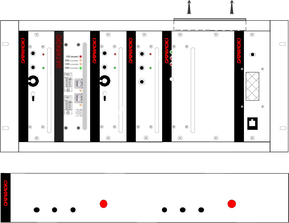
2.3 Front View:
Figure 1 - Typical rack-mount multi-modules "Radio Assembly"
Figure 2 - Typical rack-mount dual "Power Supply"
OL Stby On Power
OL Stby On Power
T800 II Slimline
®
Dual Power Supply Module
®
Receiver
®
Gating Gate
Line
Level Supply
®
Exciter
Carrier On
Line
Sensitivity
Supply
Microphone
®
Power Amplifier
Low Forward Power
Supply
High Reverse Power
Power
Sensitivity
Monitor
Volume
Off
On
Monitor
Mute
Receiver
Gating Gate
Line
Level Supply
Sensitivity
Monitor
Volume
Off
On
Monitor
Mute
Excellence in Radio
Communications
® ®
Speaker Panel
programming
port
RX2RX1
OFF
SPEAKER
SELECT SWITCH
Air Flow
BDLC-III
120 20191-001 Paragon-III Technical Manual
6
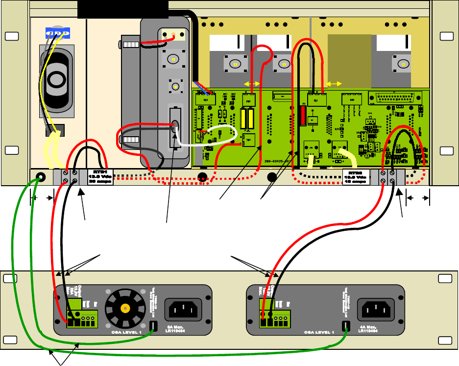
2.4 Rear Views:
Figure 3 - Base Station standard assembly
+1”
18” 15”
18” 18”
18”
For Cable Assembly details,
see drawing 730-03439-002
RTB2
+
RTB1
+-
-+
+
-
-
120 20191-001 Paragon-III Technical Manual
7
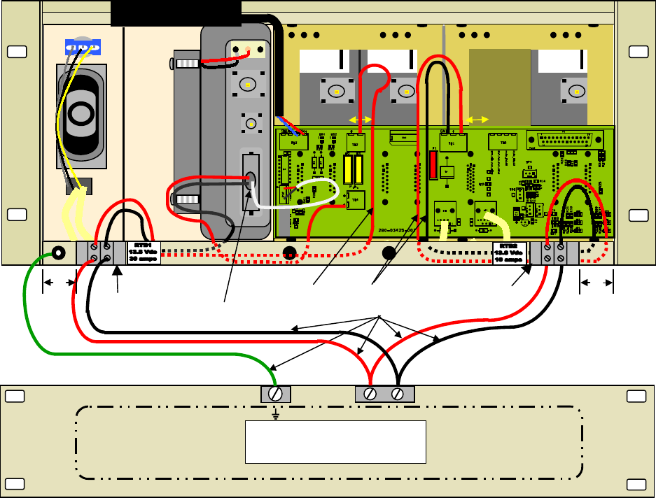
Figure 4 - Base Station standard assembly, with 3rd party DC supply module
For Cable Assembly details,
see drawing 730-03439-002
1” 1”
18” 15”
As required
Third Party Power Supply
13.8VDC Nominal
-
+
RTB2
+
RTB1
-
+-
+-
+-
120 20191-001 Paragon-III Technical Manual
8
2.5 Electrical
Standard 120 VAC electrical power is required. It should be capable of providing at least 10A to power
Paragon-III (<6A) and ancillary equipment.
2.5.1 Paragon-III Assembly Power
Two distinct power configurations (rear views) are shown in the preceding pages. They are:
• Paragon-III Base Station Standard Assy (Figure 3).
This configuration is described in paragraph 2.5.1.1 below.
• Paragon-III Base Station Assy. with 3rd party DC supply (Figure 4).
This configuration illustrates typical wiring variation required when using both a third-party
power supply and an optional DC-powered BDLC-III setup. Refer to Dataradio System
Engineering for further details.
2.5.1.1 Standard Power Supply Configuration
The Radio assembly unit receives separate 13.8 VDC power inputs from a “T800 Slimline” dual
power supply typically rack-mounted right below the main assembly radio chassis.
The T800 is made up of two separate power supply units joined in a single chassis (the second one is
used as a spare):
• A T807 using convection cooling is rated to 15A nominal at 13.8VDC. It supplies all the radio
modules other than the Power Amplifier.
Normally used at room ambient temperatures, they can operate within their specifications over a
range of –10 to +60 °C.
Note: Internal over-temperature protection shuts down the main transformer above 105 degrees Celsius.
Both power supply modules are internally connected to ground via their individual, rear-connected,
seven-foot standard 120 VAC power cords. Nevertheless, each requires a separate secure electrical
ground connection. Individual grounding tabs are provided next to the power connectors.
Similarly, the Radio Assembly chassis requires a secure ground connection. A threaded grounding
binding post fitted with a knurled binding-nut is provided on the chassis next to DC input 2. Separate
grounding leads with appropriate connectors are supplied (either in the courtesy small-parts kit or
with one end fastened to the equipment.
• For each of the power supply modules, fit one end of the grounding lead’s push-on connector
onto the grounding tab.
• For the Radio Assembly chassis, install the grounding lead’s lug over the binding post and firmly
hand-tighten the binding-nut.
• For each power supply modules
1. Fit the slotted connector (on the other end of each of the grounding connector) under a
conveniently located screw on the rack frame or other support surface. Scrape away paint
if needed to ensure clean contact.
2. Apply anti-corrosion compound where paint scraping was done.
3. Ensure by testing continuity that a secure electrical and mechanical connection is
achieved.
If a –DC rail (0V) is installed as part of the system, the grounding leads may alternatively be fit-
ted to the rail terminal.
Caution:
Improper grounding between power supply case and rack frame may result in harmful voltage potentials and/or miscellaneous power
supply switching noise problems in both receivers and transmitter.
120 20191-001 Paragon-III Technical Manual
9
2.5.1.1.1 T808/807 DC Power Supply Connection & Torque Settings
Warning: Securing the DC Power Supply cable into the DC connector to provide a good electrical
connection is essential. Over time, the wires tend to compress in the DC connector re-
sulting in an increasingly poorer connection. Consequently, as high current is drawn,
the connector heats up increasing the resistance thereby causing still more heat until the
connector eventually burns up.
Although screws securing DC cables to the Power Supply terminals are tightened to the torque set-
tings given below prior to new system delivery, they must be re-tightened as part of the commis-
sioning process and re-tightening is also part of the regular maintenance schedule.
Prior to replacing a Power Supply module into an existing system, inspect the cable and re-terminate
the DC wires if the strands have previously been twisted together or show any sign of damage.
Cut the wire at the end of the insulation and then strip approximately .4 inch (10mm) of insula-
tion off the cable. DO NOT TWIST THE WIRE STRANDS. Insert the DC cable into the screw
terminal and tighten the screw to secure the cable as per the torque settings given below.
Torque Settings:
The manufacturer recommends torque setting all power supply terminal screws to:
• 0.5 to 0.6 Nm (or 4.5 to 5.3 In/lb or to .37 to .44 ft/lb)
Note: Dataradio uses a Sturtuvan Richmond 29-pieces adjustable torque screwdriver model
CAL36/4K.
After tightening, pull on the cable to check the cable is secured tightly into the screw terminal.
2.5.1.1.2 Power Indications
• Press both red power buttons located on the front of the module to have complete power distri-
bution to the Radio assembly. The power supply front panel LEDs indications are:
Table 2 - Power Supply, LEDs indications
LED Color Indication
On Green Power enabled *
Stby Red Power disabled *
OL Steady Red Current Overload
On & OL Flashing green and red respectively Over voltage
* To remove voltage from the power supply PCB, disconnect the main power cords.
• For other Paragon-III LEDs descriptions, see section Error! Reference source not found.
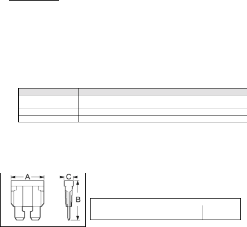
2.5.1.2 Backplane Fuses
Blade fuses (Maxi-Fuse) are used on the Radio assembly backplane (see Figure 5):
Dimensions – Inch (mm)
Fuse Type ABC
Maxi-Fuse 1.15 (29.21) 1.35 (34.29) .35 (8.89)
Figure 5 - Maxi-Fuse
120 20191-001 Paragon-III Technical Manual
10
2.6 Antenna
2.6.1 Overview
Paragon-III commonly uses three antennas (one transmit and two receive) unless a duplexer is used
with one of the receive antennas; then only two antennas would be needed. They should be mounted
according to any guidelines supplied with the antennas. For antennas placement and spacing, consult
System Engineering.
2.6.2 Cabling and Connection
1- Route good quality 50-ohm double-shielded coaxial cable(s) (e.g. RG-214 or Heliax) from the
selected antenna position(s) to the Paragon-III Radio assembly.
2- Terminate the RX-1 and RX-2 cable-ends at the Receiver modules rear position with an N-type
connector.
3- Similarly, terminate the TX cable-end at the Power Amp’s module rear position with an N-type
connector.
Caution:
When terminating RF cables use brand-name crimping tools (such as AMP, Jensen,
Crimp-Master, etc…) of the correct size for the cable and type of connector used.
Common pliers are NOT acceptable.
2.7 Completing the physical Installation.
Paragon-III products are factory-configured to user’s requirements and are shipped ready to run.
After new installations:
• Re-check that all connections are secure on the radio-BDLC assemblies (antennas, PC, power
cords etc.)
• Check that fuses are inserted.
• Turn both BDLC-III and radio power ON.
You are now ready to check for normal operation (as per paragraph 2.8) and to run the Dataradio
CDip program for testing or trouble-shooting.
Any change(s) to the settings must be done via files saved on diskette and loaded into the unit using
the CDip program.
2.8 Checking out Normal Operation
1- Check that power is applied.
2- Check Radio assembly lights for proper operation as per section 3.1.1
3- Check for proper operation of the BDLC-III’s LEDs.
4- Using the CDip program and an in-line wattmeter, check forward & reverse power to confirm
main antenna installation
5- Using CDip, check the RF Data Link with a mobile that can be heard (as per section 4.3.1)
If user application and mobiles are available, test the installation by going through a normal sequence
of transmitting and receiving messages.

120 20191-001 Paragon-III Technical Manual
11
3. Operating Description
3.1 Radio Assembly
The Radio assembly component of each Paragon product is made up of high performance synthesized
radio base station designed for single operation. The Radio Assembly’s modules are commonly
installed in a standard, 19-inch wide rack frame.
The complement of modules is identical for Series II 762-764MHz or 767-773 MHz models:
• 2 x Receivers
• 1 x 5W Transmitter (Exciter in 50W model)
• 1 x BDLC-III (controller-modem)
• 1 x Optional 50 Watts Power Amplifier (future availability)
• 1 x Speaker panel
• 1 x Dual Power Supply
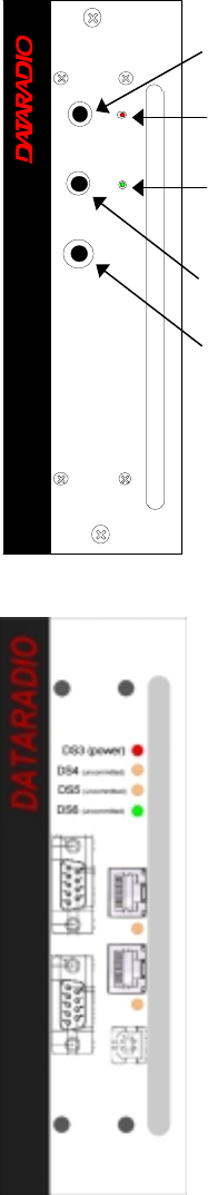
3.1.1 Receiver module
The RX1 and RX2 receivers’ use identical front panel controls and
indicators. These are:
• Gating Sensitivity - sets the RF signal level required to open the
mute gate and allow audio to pass to the speaker1.
• Gate LED - indicates the status of the mute circuit. It is lit when
a signal above the mute threshold is received1.
• Supply LED - is lit when DC power is applied. Fast Flashes
when linked with PGM800Win. Slow Flashes indicates VCO
(synthesizer) out of lock. Unequal Flashes indicates internal
communication error.
• Line Level - Not used
• Monitor Volume - The audio output delivers up to 1 watt to the
speaker. Always set volume knob to minimum when not in use
to reduce current consumption.
• Monitor Mute Switch - opens the mute, allowing continuous
monitoring of the audio signal. On = audio muted
Figure 6 - Receiver module
1 “Gating Sensitivity” and “Gate LED” are not functionally used except to allow listening to incoming receptions
as a trouble-shooting aid.
Depending on the sensitivity adjustment, the Gate LED lights and a relay can be heard on incoming RF signals.
Gating
Sensitivity
Gate
LED
Line
Level
Monitor
Volume
Monitor
Mute
On - Off
Receiver
®
Gating Gate
Line
Level Supply
Sensitivity
Monitor
Volume
Off
On
Monitor
Mute
120 20191-001 Paragon-III Technical Manual
12
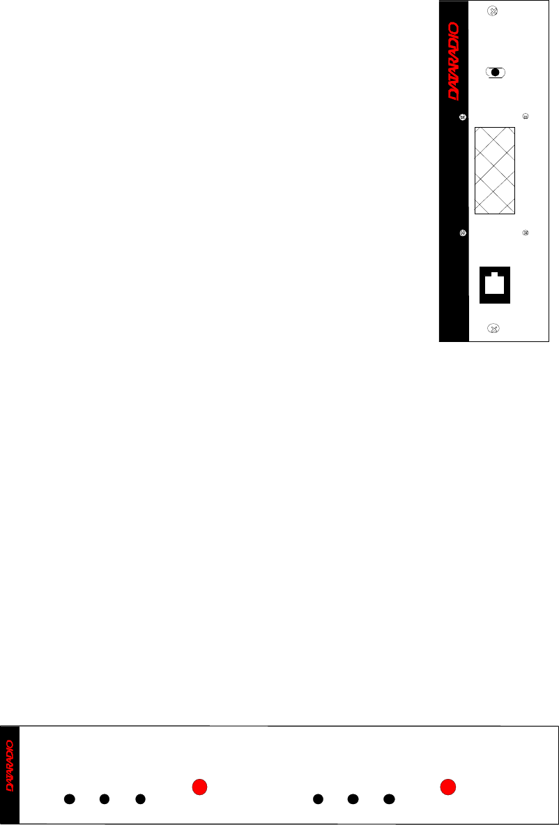
3.1.2 5W Transmitter module
The Exciter’s front panel controls and indicators are:
• Carrier Switch - momentarily keys the transmitter ON while
pressed (used for test purposes only).
• On LED - is lit when transmitting
• Line Sensitivity – not used.
• Supply LED - is lit when DC power is applied. Fast Flashes
when linked with PGM800Win. Slow Flashes indicates VCO
(synthesizer) out of lock. Unequal Flashes indicates internal
communication error.
• Microphone Socket – not used.
3.1.3 BDLC-III module
The BDLC-III's front panel connectors and indicators are:
• 2x DE-9 RS-232 ports for setup and user data
• 4x main unit status LED
• 2x Ethernet ports – for setup and user data
• 2x Ethernet LEDs (status & activity)
• USB port – reserved.
Carrier
Switch
On
LED
Supply
LED
Line
Sensitivity
Microphone
Socket
®
Exciter
Carrier On
Line
Sensitivity
Supply
Microphone
120 20191-001 Paragon-III Technical Manual
13
3.1.4 Speaker panel
The speaker panel is fitted with a four-Ω speaker.
Both series of radio assemblies share the same front panel fitted with an
RJ11 connector. This connector is used to allow programming the radio
from the front of the unit via a programming lead. This feature is exclu-
sive to the Series II modules.
If the speaker panel needs to be removed, a mirror programming port
connector is provided on the backplane.
Figure 7 - Speaker module
3.1.5 Dual Power Supply module
The Dual Power Supply module is made up of two separate power supply units coupled in a single
chassis.
Refer to:
Table 2 on page 9 for tabular listing of power supply LEDs indicators and Figure 8 below.
This module has:
• Two “Power” red-colored pushbutton switches - Push in for ON and release out for OFF. Control
complete power distribution to the Radio assembly
• Two “ON” LEDs - light green when push button(s) is (are) ON; DC power is distributed to radio
modules. Flash green in conjunction with the “OL” LED (flashing red) when an over voltage
condition is present.
• Two “Stby”- Standby voltage LED, lights red when push button is off; AC power is applied but
DC is not distributed to radio modules. To remove presence of voltage, disconnect both power
cords.
• Two “OL” LEDs - Monitor current overload, light steady red when supply exceeds current limit
set; nominally 25Amps (T808 model). Flashes red in conjunction with the ON LED (flashing
green) when an over voltage condition is present.
Figure 8 - Dual Power Supply Module front panel
®
S peaker Panel
programming
port
RX2RX1
OFF
SP EAK ER
SELE CT SWI TCH
OL Stby On Power
OL Stby On Power
T800
II
Slimline
®
Dual Power Supply Module
120 20191-001 Paragon-III Technical Manual
14
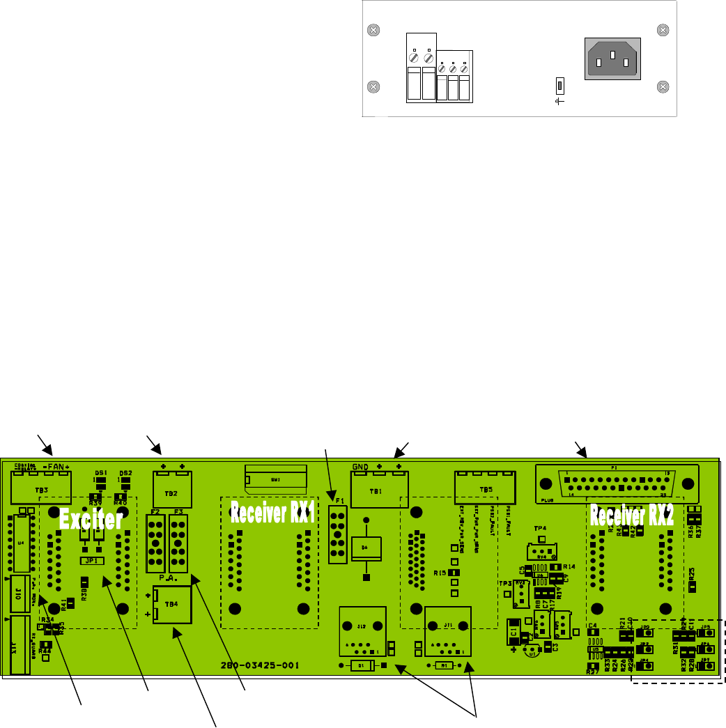
3.1.5.1 Power Supply Rear Connections
The rear connections (convection-cooled model shown; fan-cooled model not illustrated) for each of
the power supply are:
Fail Alarm –
Off: Power supply OK; approx. +Vout (via 1k resistor - typ. 13.8V).
ON: Power supply failure; approx. -Vout (via 11k resistors - typ. 0V)
+ Remote – Not used for Paragon
- Sense – Not used for Paragon
-VE – main ground (0V)
+13.8V – Mains DC output supply
Note: more power supply installation details
are covered in section 2.5.1
F
igure 9 - Dual power supply, rear connections
3.1.6 Radio Backplane Assembly
A single PCB backplane is used. The main components are:
• RJ11 connectors (J11, J12) – connects to the Speaker panel front RJ11. Used for program-
ming the Radio modules.
• DB-25F port to ancillary equipement
• One channel-select DIP switch (SW1)
• Cooling fan driver – TB 3 located on backplane connects to the horizontally-mounted fan on
top of the Radio assembly and activated by BDLC’s PTT signal (setting JP1 2-3 will power
the fan continuously).
• 30 A Fuse (F2 & F3) – two blade fuses (15ADC) in parallel are used for future Power am-
plifier
• 10 A Fuse (F1) – one blade fuse to power the other base station components (receivers, ex-
citer and optionally the BDLC).
Figure 10 - 280 03425-001 Radio backplane
15A
+
-
Output
Sense
+
-
Remote
Fail Alarm
13.8V
Max.
Top fan 13.8VDC input from
T808-10-00CA 13.8VDC input from
T807-10-00CA RS-232 DE25F
Maxi-Fuse - 10 Amp.
13.8 VDC output to T889.
Maxi-Fuses - 2 x 15 Amp.
RJ 45 Connectors #1
1 2 3
JP1 - Fan
Control
1
8
1
8
J2 J1 J6 J5
P.A. diags signals
(future use)
Molex connector

120 20191-001 Paragon-III Technical Manual
15
4. Trouble-Shooting and Testing
The checks described below should be done at time of installation, annual intervals, or whenever de-
terioration in performance is noted.
4.1 Equipment Required
• In-line watt meter (10 W range)
• Radio service monitor (IFR-120B with option 03: 30KHz IF filter or equivalent).
• RG-214 or RG-223 cable with N-Type male connector to connect Paragon-III to the service
monitor.
• CDip 1.0 or later1
Important note: Before proceeding make sure that the service monitor has been calibrated re-
cently and has warmed up for at least the time specified by its manufacturer.
Some reported frequency and deviation problems have actually been erroneous indications from
service monitors that have not adequately warmed up. This is particularly likely when field service is
done during winter months.
4.2 Recommended Checks
A) After an installation
1. LED Indications
2. Using CDip, Save “unit config” to a file
3. Transmitter Output Power
4. Transmitter Reflected Power
5. RF Link test between Paragon-III and mobile unit(s)
B) For annual maintenance & trouble-shooting
Same checks as A) plus:
6. Carrier Frequency Error
7. TX Deviation
8. Low Frequency Balance
9. 12 dB SINAD
10. Receiver distortion
11. RSSI check
12. Verify power supply connections & terminals torque settings (see paragraph 2.5.1.1.1)
1 To learn how to launch the Windows-based software alignment and system-testing tool CDip, please refer to
the readme.txt file on the application’s installation diskette.
For functional details of the numerous buttons and menu-selectable items available, please refer to the pro-
gram’s context sensitive help. It is also possible to access the help information via the F1 key.

120 20191-001 Paragon-III Technical Manual
16
Table 3 - Checklist A (After installation)
CHECKLIST A
(Paragon-III)
Recommended Check out after Installation
Step ACTION EXPECTED RESULTS
at 25°
°°
°CMEASURE WITH IF NOT?
1Normal Power-up
Sequence BDLC-III beeps once, all LEDs come ON for about four seconds, the green
LEDs then flash in a “ripple” pattern for close to two seconds. All LEDs go OFF
except the CK that should flash 6 to 8 times per second.
2Connect and save unit
config
Press CDip Get button
as per CDip Help content
3Transmitter Output
Power
Press TXON (Unmod)
5 watts
+0%, -10%
Service monitor set
to read power
or
10W in-line watt-
meter installed as
close as possible to
the unit antenna
connector.
Check for bad connections,
damaged coax cable, etc.
4Transmitter Reflected
Power
Press TXON (Unmod)
< 5% of forward power or
as specified by System
Engineering.
10W in-line watt-
meter Check for bad connections,
damaged coax cable, etc.
5RF Link test
Use the mobile address
function and “Send” but-
ton to dynamically test
the link
Look for
“Delivery confirmed” on
the Status bar
Refer to 4.3.1 and to
CDip Help content.
Mobile is out of range
Refer to factory technical
support.

120 20191-001 Paragon-III Technical Manual
17
Table 4 - Checklist B (General)
CHECKLIST B (Paragon-III)
General Check out (part1 of 2)
Paragon-III units are set and characterized at the factory to optimize performances.
It is not recommended to try readjusting units unless it is really required.
Misadjusting a unit may result in significant performance losses.
The proposed adjustments in the "IF NOT?" column below, should be tried ONLY if system data
performance degradation is noticed combined with out-of-tolerance items.
Step ACTION Expected Results at 25°
°°
°CMEASURE WITH IF NOT?
1Normal Power-up
Sequence BDLC-III beeps once, all LEDs come ON for about four seconds, the green LEDs then
flash in a “ripple” pattern for close to two seconds. All LEDs go OFF except the CK that
should flash 6 to 8 times per second.
2Connect and save unit
config
Press CDip Get button
as per CDip Help content
3
Transmitter Output
Power
Press TX ON (Unmod)
5 watts
+0%, -10%
Service monitor set
to read power
or
10W in-line watt-
meter installed as
close as possible
to the unit antenna
connector.
Adjust “Power” on the front
panel of the “Power Amp”
4Transmitter Reflected
Power
Press TXON (Unmod)
< 5% of forward power or as
specified by System Engi-
neering.
10 W in-line
wattmeter Check for bad connections,
damaged coax cable, etc.
5Carrier Frequency Error
Press TX (Unmod)< ±300 Hz Service monitor set
to read frequency
error
Adjust TCXO (IC700)
(see inside Exciter module at,
Figure 18
6TX Deviation (KHz)
Press
TX (modulated)
Carrier will be modulated
with a 1 kHz tone.
±8.0 kHz
Tolerance is +5%, -10%
Service monitor set
to read deviation.
(IF filter set to Mid
or 30 kHz position) Refer to tech support
7Low Frequency
Balance
Initiate a
TX Random data test
via CDip
a) Record deviation level
read from step 6
b) Record deviation read
from TX Random test
c) Difference between
a) and b) should be:
< 1.5 kHz xRC16FSK)
< 1.7 kHz xRC8FSK)
< 1.9 kHz xRC4FSK)
Service monitor set
to read deviation
(IF filter set to Mid
or 30 kHz position,
all audio filtering
disabled )
Refer to
Section 5.2.3.4

120 20191-001 Paragon-III Technical Manual
18
CHECKLIST B (Paragon-III)
General Check out (part2 of 2)
Paragon-III units are set and characterized at the factory to optimize performances.
It is not recommended to try readjusting units unless it is really required.
Misadjusting unit may result in significant performance losses.
The proposed adjustments in the "IF NOT?" column below, should be tried ONLY if system data
performance degradation is noticed combined with out of tolerance items.
Step ACTION EXPECTED RESULTS at
25°
°°
°CMEASURE WITH IF NOT?
Set the service monitor to generate on the selected receive frequency. Verify alternately for both receivers.
The carrier should be modulated with a 1.0 kHz tone at deviation level specified below:
8
12 dB SINAD
(Dataradio wide band
measurement method: no
audio filtering)
Set deviation to ±8 kHz.
Better than -108 dBm
including cable loss
(Typically -109 to -110 dBm)
- Backplane corre-
sponding to the re-
ceiver being verified:
J1 (RX1) or J5 (RX2),
Pin 6 (see Figure 10,
page 14)
- Service monitor (IFR)
set to SINAD
- IFR IF filter set to MID
position or 30 kHz wide
filter.
Refer to section 5.2.2
9
Receiver distortion
(Dataradio wide band
measurement method: no
audio filtering)
- Set service monitor RF
Gen output to –70 dBm
- Deviation level as per
SINAD above.
≤ 5.5 %
(Typically < 3.5 %)
- Backplane corre-
sponding to the re-
ceiver being verified:
J1 (RX1) or J5 (RX2),
Pin 6 (see Figure 10)
- Service monitor (IFR)
set to DISTORTION.
- IFR IF filter set to MID
position or 30 kHz wide
filter.
Refer to section 5.2.2
10 RSSI
Apply to each receiver
input the following RF
level of -110dBm 2.0 VDC (+/- 0.3VDC)
- Backplane corre-
sponding to the re-
ceiver being verified:
J1 (RX1) or J5 (RX2),
Pin 5 (see Figure 10)
- DC Voltmeter
measurement
Refer to section 5.2.2.5 for
all models.
Refer to factory technical
support only if RX data
performance degradation is
noticed combined with out
of tolerance RSSI readings.
120 20191-001 Paragon-III Technical Manual
19
4.3 Additional test details
4.3.1 RF Data Link Test
A link test between a mobile and a known base station can be done using the CDip "Address" and
"Send" functions. The “Address” and “Device” fields, the “Send” button and the “Chat” message
screen are used to send messages to specific mobile or base or to carry out RF test. Start by entering
the address of the mobile (or base station) you wish to send a test message to or test:
1- Specify the address:
Addresses may be entered by typing directly in the “Address” field in two ways:
- Numerically, the valid address range is 1-126.
- As an “Alpha-Mapped-Nibble” (AMN) address, consisting of upper case letters in the range
A-P.
The valid address range is A to GN.
- The base address is usually: 1.
- The program may display one of the following messages on the status bar:
- For Paragon-III products:
“address is not in AMN or number format”
- For mobile products:
“address is not in the range A – GN”
In either case, check that the address entered is within the acceptable range, is of a valid format
and correctly typed.
2- Enter the Device number for mobile (or base station).
3- Press the Send button.
The Chat window reports “Sent to xx mobile” (where xx is mobile name).
If test is successful:
Status line reports “Delivery confirmed.
If test unsuccessful:
Chat window reports “Waiting”,
Then the Status line reports “Delivery Failed”.
120 20191-001 Paragon-III Technical Manual
20
5. Radio Programming and Adjustments
All receiver procedures detailed in this section should be done twice: once for the “Main” (or RX1)
receiver module and a second time for the “Auxiliary” (or RX2) receiver module. Connect to the
relevant module and its corresponding backplane PCB as required.
5.1 Series II Radio Programming
This procedure describes the steps needed to program the Paragon-III radio base station 700 MHz.
5.1.1 Recommended Items
- 486 PC or better, MS-Windows 98 © or later
- T800win programming kit for Series II:
- PGM800Win programming software user's manual
- PGM800Win Windows based programming software version 3.0 or later
- T800-01-0002 programming cable (DB-25 to RJ-45 cable)
- Standard 25-pin parallel cable (terminated Male/Female)
5.1.2 Module Programming
Before starting programming, have a PC running MS-Windows © and the Tait PGM800Win soft-
ware for Series II Base station.
This program supports the use of a mouse but may be used without one if required. Keyboard access
follows the conventional MS-Windows © method as briefly described below:
- Press and hold the “Alt” key while pressing at the same time the relevant hotkey as indicated by
an underlined letter on the menu command.
- On a drop-down menu, press only the hotkey without pressing the “Alt” key.
- Use the “Tab” key to cycle available fields and the “Enter” key to validate entries. E.g. Pressing
“Alt”+F opens the File drop-down menu and pressing “A” opens the Save As directory service box.
• Receiver VCO and front-end alignment will be required when new receiver frequency is pro-
grammed outside the radio tuning range:
792-794 MHz = ± 3.0 MHz from previous center frequency
797-803 MHz = ± 3.0 MHz from previous center frequency
• Exciter will be required when new transmitter frequency is programmed outside the radio tuning
range: ± 4 MHz from previous center frequency.
1. Connect the PC, via the supplied programming lead, to the speaker panel’s front-mounted
RJ11 connector.
2. Run Tait PGM800Win program and follow instructions found in the T800 Programming
Software User’s Manual to select the proper module to be programmed.
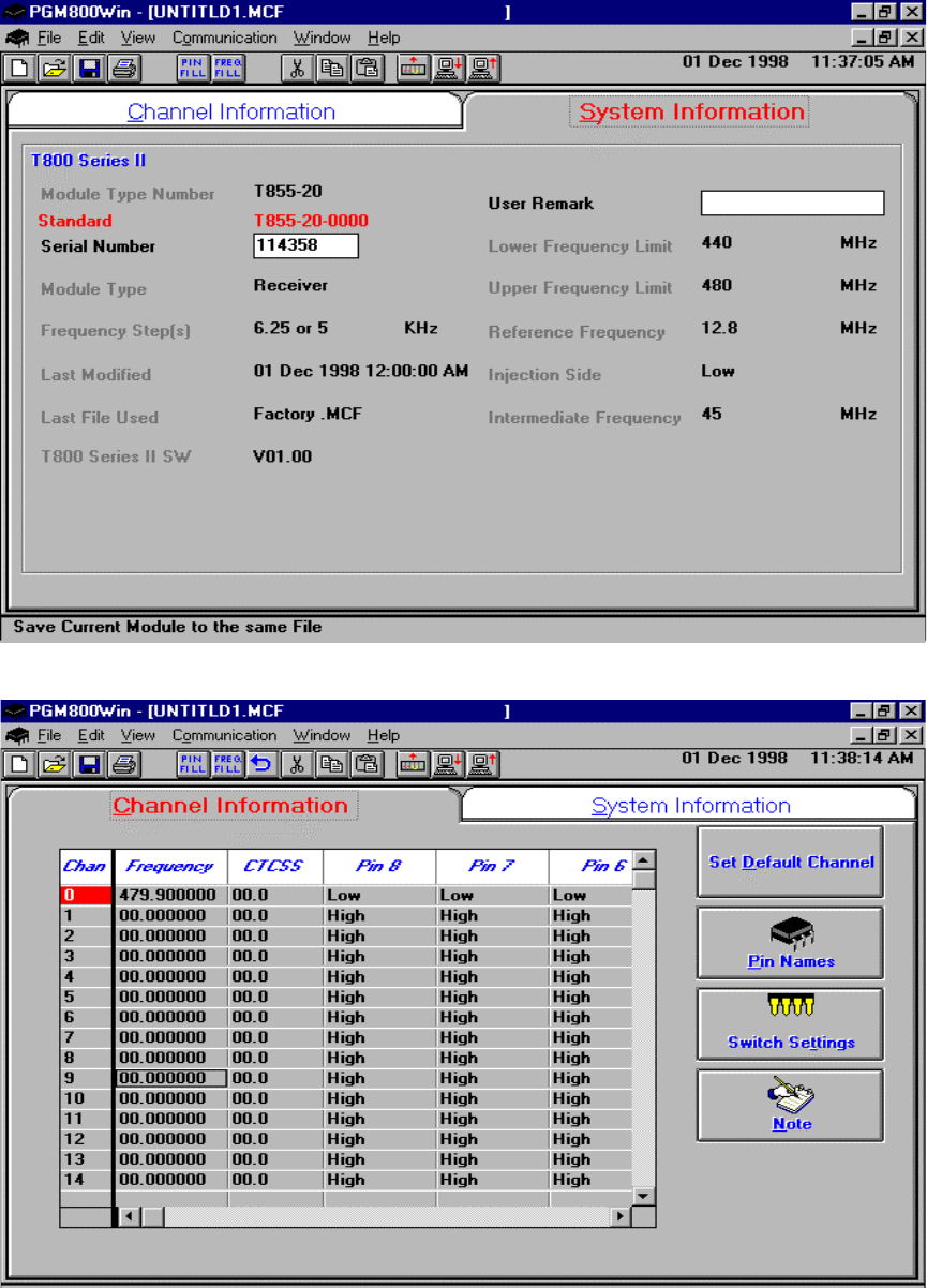
3. Program required channel's frequencies.
– Do not program any CTCSS tones on channels.
– Do not change any other parameters.
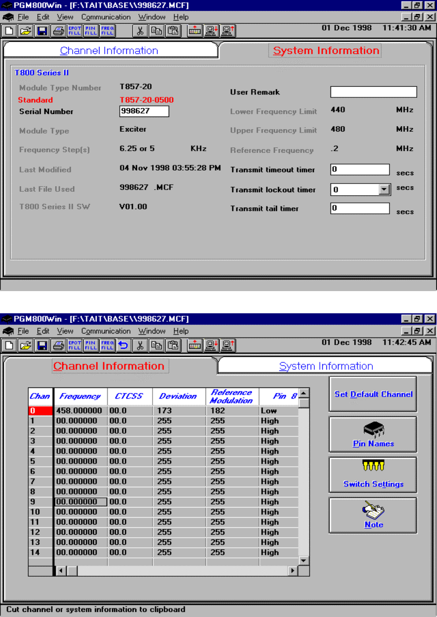
– Refer to Figure 11, Figure 12, Figure 13 and Figure 14 for screen program examples.
4. Save the base station programming info to a file for further reference.
120 20191-001 Paragon-III Technical Manual
21
Figure 11 - Receiver System Information Sample
Figure 12 - Receiver Channel Information Sample
120 20191-001 Paragon-III Technical Manual
22
Figure 13 - Exciter System Infomation Sample
Figure 14 - Exciter Channel Information Sample
120 20191-001 Paragon-III Technical Manual
23
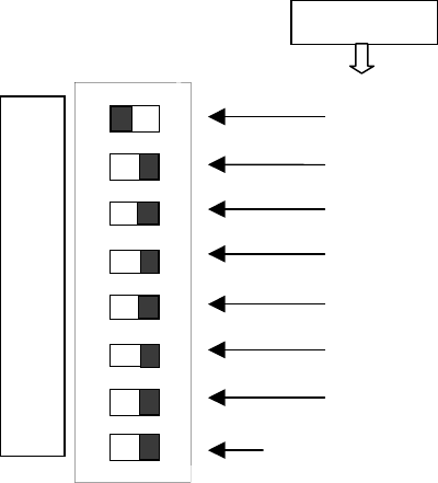
5.1.3 Channel Selection via DIP Switches
The backplane-mounted DIP switch settings override the default channel programmed by PGM800Win.
To set a default channel via the software, all DIP switches must be set to “OFF” (i.e. 00000000).
When a switch is “Off”, its binary count is active; when a switch is “ON” its binary count is inactive. The
various DIP switch combinations of ON or OFF make up a binary total, which identifies the channel
number.
To select a channel, set the appropriate DIP switch or switches to “OFF” to make the binary count total
the channel number you want. Set all other switches to “ON”.
Example: To select channel 1, set the DIP switches as shown below:
Figure 15 - Backplane DIP switches example - Channel 1 selected
Binary Value
1
2
4
8
16
32
64
Always ON except when
default channel is required
CHANNEL SWITCH TX - RX
1
2
3
4
5
6
7
8
O
F
F

120 20191-001 Paragon-III Technical Manual
24
5.2 Series II Radio Tuning
- This section covers the basic Series II base station 700MHz radio modules radio tuning and
verification.
Note: Usually, this section is never done unless called for in section 5.1 “Series II - Radio Pro-
gramming” or in Table 4 - Checklist B (General)“Checklist B” (General).
5.2.1 Test Equipment
- Digital Multimeter & probes (e.g. Fluke 77)
- 1 HP 34330A Shunt 30A (UHF only, used for transmitter current measurement)
- Digital or Analog calibrated Oscilloscope & scope probes (X1, X10 selectable)
- Calibrated COM-120B (.001ppm OCXO and 30kHz IF options)
- 3-foot length of double-shielded N-M to BNC-M cable (RG-214 or RG-223)
- 2x 'BNC' to 'N' type adapters (e.g. Amphenol, Greenpar).
- Bird RF power meter with 150W / 50 ohm dummy load (optional)
- 3dB 150–watt attenuator
- 1x Torx screwdriver #T-10 and #T-20
- Pozidriv screwdriver #1 & #2
- 1x Six-inch adjustable wrench
- RF tuning/trimming tools.
- Extender Rail Kit for Series II chassis (T800-13-0000)
- 1x 6" coax cable N-M to BNC-M (comes with the radio to connect the exciter to the PA)
5.2.2 Receiver module
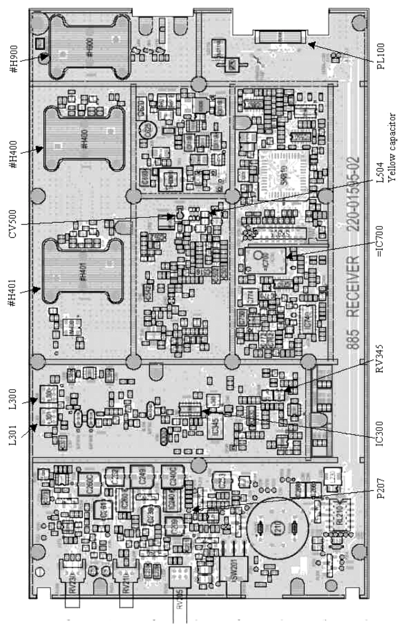
Note 1: Refer to Figure 17 (T885)
Note 2: When the synthesizer is unlocked, the front panel green LED called "Supply" will flash
indicating that it needs re-tuning.
Warning,
The LED will also flash when the unit is in setup mode while connected to the
PGM800win program.
5.2.2.1 Initial Setup
This initial setup will be used during all receiver alignment procedures described below:
1. Remove the receiver (T885) module from the Paragon-III rack frame
2. Remove the receiver top cover (nearest the handle).
3. Connect the Paragon-III Extender Rail Kit for Series II to the empty chassis receiver slot.
4. Prepare the Multimeter to DC Volts.
5. Apply power to the Paragon-III.
5.2.2.2 Synthesizer Alignment
Single channel: Connect the Multimeter to either side of L504 (T885) in the VCO (this measures
the synthesizer loop voltage).

120 20191-001 Paragon-III Technical Manual
25
- T885 (800/900 MHz) Tune VCO trimmer CV500 for a synthesizer loop voltage of 10VDC.
Multiple channels (adjusting as shown for single channel above):
1. T885 Adjust the VCO loop to 10V using the middle frequency channel.
2. All channels should lie within the upper and lower limits of respectively
All channels should lie within the upper and lower limits of 16V and 3V for the T885.
5.2.2.3 Front-End Alignment
1. IFR COM120B settings:
a) Connect a 3 feet long double shielded cable (N-M to BNC-M) between the IFR T/R output and the
receiver antenna connector.
b) Select the generator mode (GEN button) and set to the main receiver channel frequency
c) Select and turn-on GEN2
d) Set the FM Deviation to ±3kHz (full channel) or ±1.5kHz (half channel) using 1KHz sine
e) Select SINAD meter
f) Use a X1 scope probe connected to SINAD input and monitor the Discriminator O/P on the back-
plane at SK1 pin 6 (RX-audio1). Alternately, it is also possible to monitor at the receiver I/O Pad
P207 (T885).
2. Adjust the helical resonators for best SINAD: #H400, #H401 and #H900 (T885).
3. Continually decrease the RF level to reach 12dB SINAD, then re-do step 2) & 3) again. The absolute
minimum requirement level to reach is -108dBm (typical level is -109 to -110 dBm)
4. Perform the SINAD linearity tests described in paragraph 5.2.2.4. If it fails to pass the requirement,
contact your Dataradio technical support.
WARNING: Do NOT attempt to re-tune the IF stages
(I.e. L300 and L301 for T885)
These adjustments do not need to be re-adjusted after frequency re-programming. Touching these
coils will have a direct impact on the modem DSP ISI coefficient settings and may reduce signifi-
cantly the radio performances over data.
5.2.2.4 SINAD and Linearity Check
1. Apply the following settings to the IFR COM-120:
a) Generator mode, Output T/R, TX frequency to match the main radio RX frequency
b) Filter set to wide band (no audio filter)
c) Select Gen2 (Modulating tone fixed to 1KHz). All other Gen must be off.
d) Set deviation to ±3.0KHz for full channel or ±1.5KHz for half channel radios.
e) Use a X1 scope probe connected to the IFR SINAD input and monitor the Discriminator O/P on the
radio backplane at SK1 pin 6 (RX-audio1). Alternately, it is also possible to monitor at the receiver
I/O Pad P207 (T885).
2. Lower the RF level to get a 12dB SINAD reading. Level should be better than -108dBm (including ca-
ble loss).
3. Offset the IFR TX frequency 2kHz above the main radio RX frequency, record the SINAD reading. It
should remain within 1.5 dB from the on frequency SINAD reading.
4. Offset the IFR TX frequency 2KHz below the main radio RX frequency, record the SINAD reading. It
should remain within 1.5 dB from the on-frequency SINAD reading.
Note: If one of the above requirements is not met, try to re-tune the front-end. If still failed, contact
your Dataradio technical support.

120 20191-001 Paragon-III Technical Manual
26
5.2.2.5 RSSI Adjustment
- Caution: mis-adjusting RSSI may reduce the Paragon-III's Parallel Decode (PD) performance.
- BDLC-III must be connected to the radio chassis assembly during this process.
1. T885-xx-0200 (700MHz) receivers:
- Refer to Figure 17 - T885-0200 Receiver Tuning Controls location
- Apply an on-channel signal from the RF generator at a level of -110 dBm modulated by a 1 kHz tone at
a deviation of ±6kHz.
- Adjust RV 345 (RSSI level) for T885 to give 2.0V RSSI output at SK330 pin 2 or on backplane J1
(RX1) or J5 (RX2) pin 5 when measured with a voltmeter (See Figure 10 - 280 03425-001 Radio back-
plane for test point location).
The following RSSI graphics are given as general information only.
Refer to factory technical support only if RX data performance degradation is noticed combined with
something that does not look like those RSSI curves.
Figure 16 - T885, Typical RSSI Curve: volt to dBm
5.2.3 Exciter Module (T881-xx-0200)
Note 1: Refer to Figure 18 (T881).
Note 2: When the synthesizer is unlocked, the front panel green LED called "Supply" will flash indi-
cating that it needs re-tuning.
Warning:
The LED will also flash when the unit is in setup mode while connected to the PGM800win program.
5.2.3.1 Initial Setup
1. Shut down power to the base station.
2. Prepare the Multimeter to DC Volts.
3. Remove the exciter (T881) module from the base station rack frame.
4. Remove the exciter top cover (nearest the handle).
0
1
2
3
4
5
6
7
-120 -110 -100 -90 -80 -70
dBm
Voltage

120 20191-001 Paragon-III Technical Manual
27
5. Connect a 3 feet long double shielded cable (N-M to BNC-M) between the IFR T/R output and
the exciter antenna connector.
6. Connect the Paragon-III Extender Rail Kit to the empty chassis exciter slot.
7. Apply power to the base station.
5.2.3.2 Synthesizer Alignment
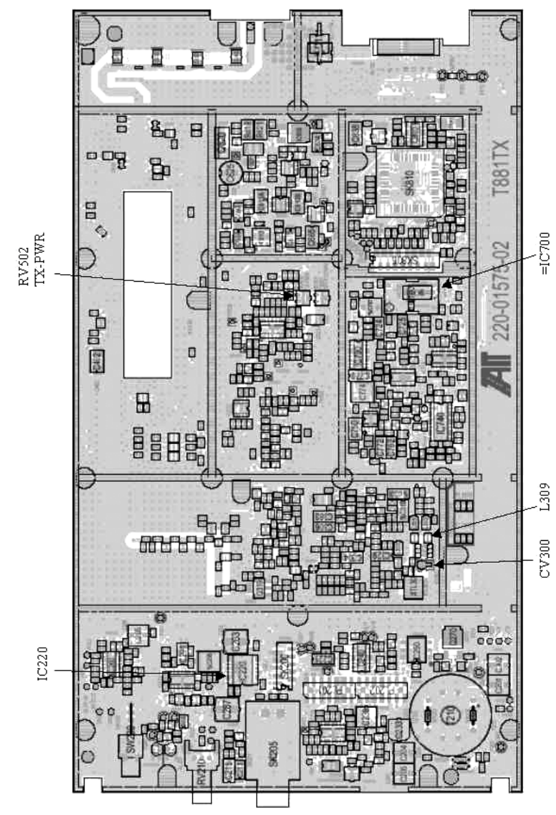
Single channel: Connect the Multimeter to either side of L309 (T881).
- T881 (700 MHz) Tune VCO trimmer CV300 for a synthesizer loop voltage of 10V DC.
Multiple channels (adjusting as shown for single channel above):
- T881 (700 MHz) Adjust the VCO loop to 10V using the middle frequency channel.
All channels should lie within the upper and lower limits of 16V and 3V respectively for the
T881.
Note: Normally, the fast TX key option is installed and the synthesizer is always ener-
gized. In the case where that option was not fitted, key the transmitter by pressing
the front panel Carrier button to make the above adjustment possible.
5.2.3.3 TX Frequency Error Adjustment
1. Apply the following settings to the IFR:
- Receiver mode
- IFR RX frequency to match the main radio TX frequency
- IF Filter set to 30KHz
- Zoom the RF Error window: select 10Khz range
2. Key the transmitter by pressing the front panel TX-Key button and measure the carrier output
frequency. It should be within ±300 Hz. If it is not, adjust the TCXO (IC700) to trim to meet the
requirement, preferably within 100Hz.
120 20191-001 Paragon-III Technical Manual
28
5.2.3.4 Low-Frequency Balance Adjustment
Note:
• PGM800Win version 3.00 or later must be used. Electronic potentiometer (256 step) is
used to allow channel adjustment of two-point modulation (Low freq. balance).
1. Apply the following settings to the IFR:
– Receiver mode and Oscilloscope display (Source Demod out connector, DC coupled).
– IFR RX frequency to match the radio transmit frequency
– IF Filter set to 30KHz
– Zoom the Deviation window: select 10kHz Range and DC coupling.
2. Select the active or, the lowest (in the case of multi-channel base) frequency channel (via dip
switch, refer to Figure 14)
3. Transmit a square wave by using CDip (using a second serial port).
4. Press EPOTs button. Adjust IC220 via PGM800Win “reference modulation” to obtain the best
square wave, no damping, no overshoot. (You can use either the mouse or up and down arrow
keys). Record the deviation read.
5. For single-channel unit, proceed to step 8.
6. For multi-channel unit, select the highest frequency channel. Transmit a square wave via CDip.
Record deviation again.
7. The difference in deviation between the two channels should be less than ±300Hz. If not, re-
adjust IC220 to "average" the square wave shape on both channels until the spec is met.
8. To confirm the adjustment, select the active, or the lowest frequency channel. Compare the de-
viation produced between 1000 Hz sine wave test tone and Random data test pattern
The difference between the test tone and the test pattern should be less than 1.9 kHz for
xRC16FSK modulation set
For multi-channel unit, repeat this step on the highest frequency channel.
9. Select the active channel. Transmit a TX ON (Modulated) adjustment tone via CDip. Make sure
that deviation level read on the IFR correspond to bit rate in use (see Table 4 at step 6). Re-adjust
deviation as necessary.
5.2.3.5 Exciter Power Output
1. Apply the following settings to the IFR:
- Receiver mode, Output T/R
- IFR RX frequency to match the main radio TX frequency
- IF Filter set to 30KHz
- Select auto range in the Power reading window
- Connect the coaxial cable from the IFR T/R to the Exciter output connector
2. Key the Exciter by pressing the module PTT button. The output power at the coaxial cable end
connecting to the power amplifier should be:
- T881 = 5W +0/-300mW (RV502, Figure 18)
120 20191-001 Paragon-III Technical Manual
29
-
Figure 17 - T885-0200 Receiver Tuning Controls location
120 20191-001 Paragon-III Technical Manual
30
Figure 18 - T881-0200 Exciter Tuning Controls location

120 20191-001 Paragon-III Technical Manual
31
6. Specifications
GENERAL
Frequency 762 -764 MHz Tx/ 792-794 MHz Rx and 767- 773MHz Tx/797-803MHz Rx
RF/Modem Assembly Size 19.0” W x 17.5.0” H x 12.5” D + 2.0” connector allowance
Frequency Stability 1.0 ppm (-20 to +60ºC)
Supply Voltage
13.8 VDC nominal (negative ground), 10.8 - 16 VDC
or
120 VAC
Circuit protection (radio backplane)
Main fuse (F1): Blade fuse (Maxi-Fuse) 10A :
Power amp. fuse (F2 & F3): Blade fuses (Maxi-Fuse) 2 x 15A (30A total)
Crowbar diodes for reverse polarity protection
RX Current Consumption @ 13.8
VDC 1.5A max. (Two receivers with speaker monitoring)
TX Current Consumption @ 13.8 VDC 1.7A max
Base Station Power Consumption
@ 120 VAC TBD
Channel spacing 50 kHz
Operating Temperature Range -30°C to +60°C (deleted power supply, catalog number with 0 in second to last digit)
-10°C to +60°C (with standard Dual Power Supply assy., catalog number with 2 in second to last digit)
RECEIVER
Selectivity @ 25 kHz
@ 12.5 kHz
85 dB min, 88 dB (Typical)
79 dB min, 80 dB (Typical)
Sensitivity @ 12 dB SINAD -116 dBm*
Spurious Response Rejection 100 dB (Typical)
Intermodulation Rejection
- EIA (25 kHz)
- EIA 300-096 (12.5 kHz) 80 dB (Typical)
75 dB (Typical)
Hum and Noise
- EIA (25 kHz)
- ETS 300-096 (12.5 kHz) 47 dB*
45 dB*
* Psophometrically weighted (De-emphasis response)
TRANSMITTER
Rated Continuous RF Power 5W nominal
Range of Adjustment 1 – 5 W
Spurious Emissions: - transmit
- standby
-36 dBm to 1GHz, -30 dBm to 3.2GHz
-57 dBm to 1GHz, -47 dBm to 3.2GHz
VSWR Stability 3:1 mismatch
Transmitter Sideband Noise (ACP)
@ +/-50 kHz
@ +/- 1 MHz
-40 dBc
-100 dBc
120 20191-001 Paragon-III Technical Manual
32
Operation Full duplex
Protocol Dataradio Proprietary E-DBA with OOB AAVL support
Data rates and
Modulation type
xRC16FSK (128 kb/s)
xRC8FSK (92 kb/s)*
xRC4FSK (64 kb/s)*
* Operating under Class I permissive change, subset of 16-Level FSK
FCC CERTIFICATIONS FCC IC (DOC)
762-764MHz and 767-773MHz EOTBDP3-T881 NA
EMISSION DESIGNATORS
Bit rate Baud rate Modulation 700MHz
128 kb/s 32000 xRC16FSK 30K0F1D