CalAmp Wireless Networks BDP4-EXT8 Exciter 800MHz User Manual TITLE

CALAMP WIRELESS NETWORKS INC. Exciter 800MHz TITLE

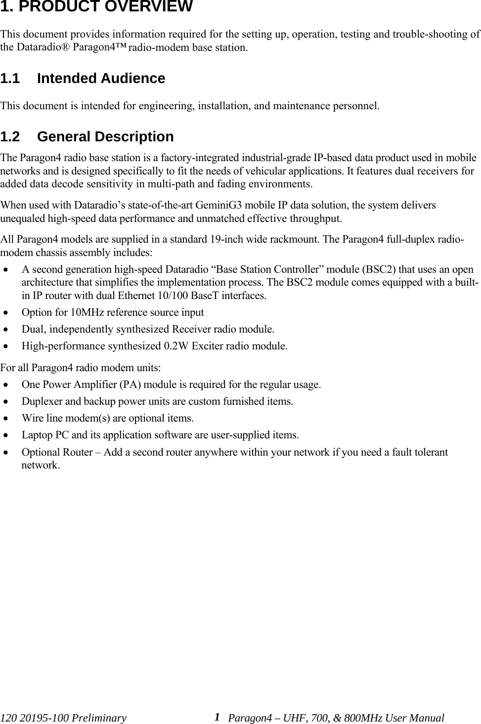
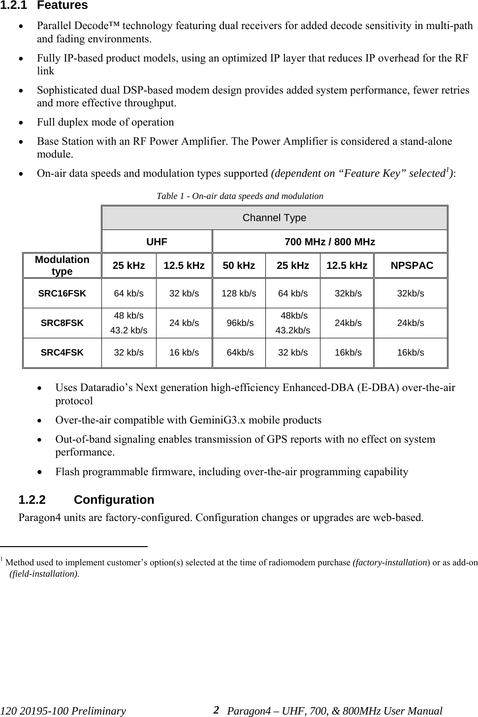
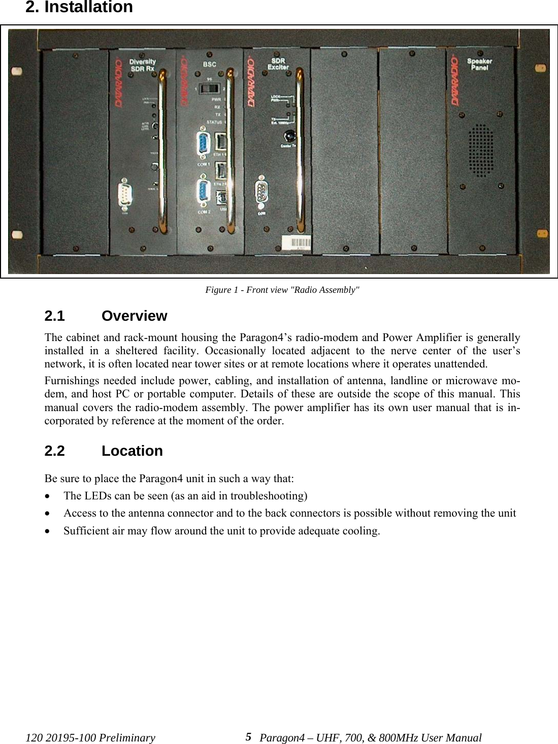
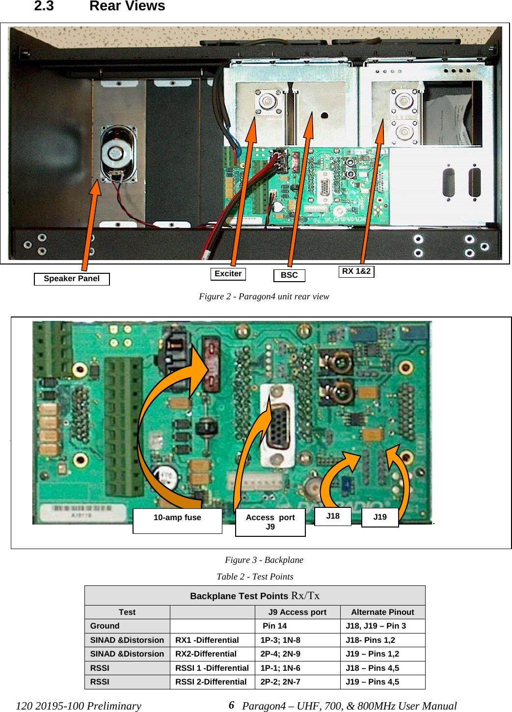
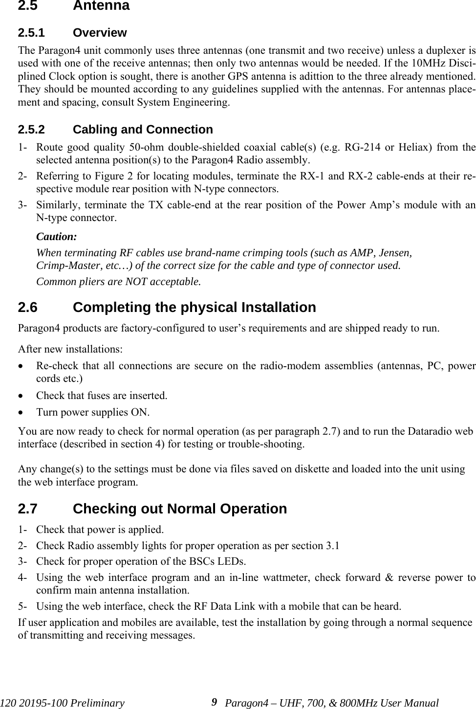
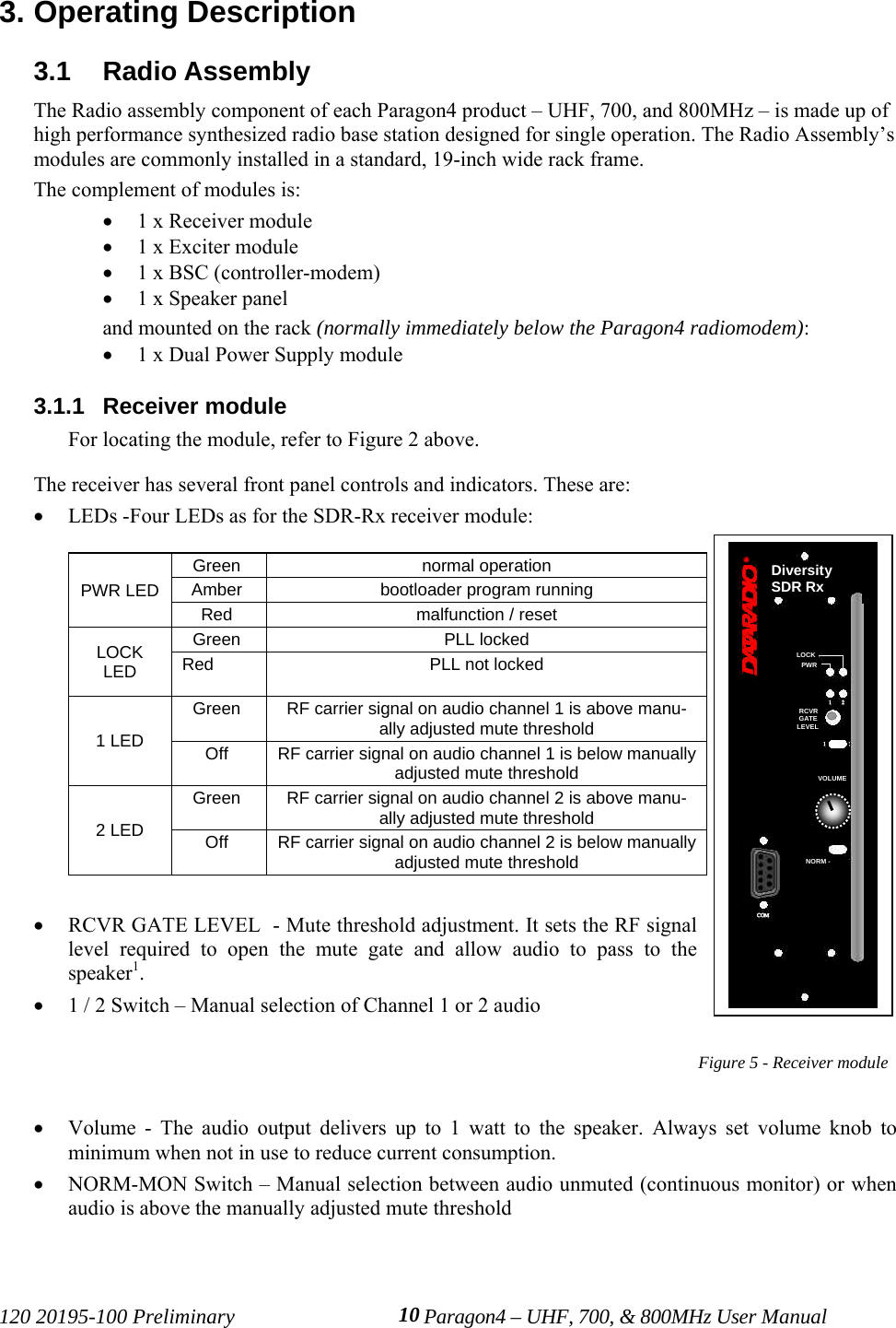
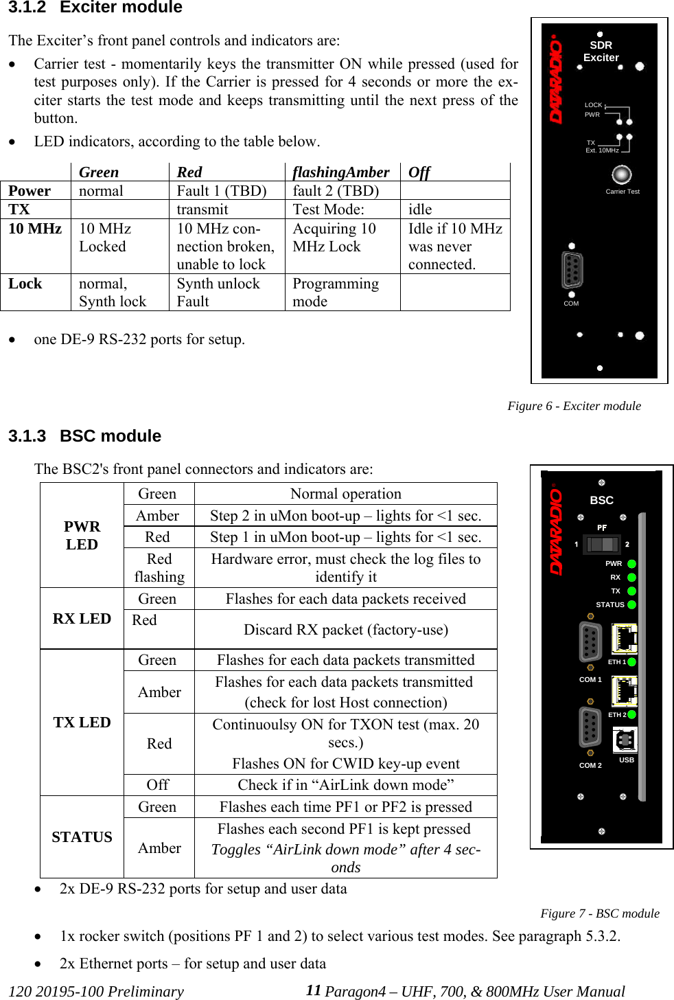
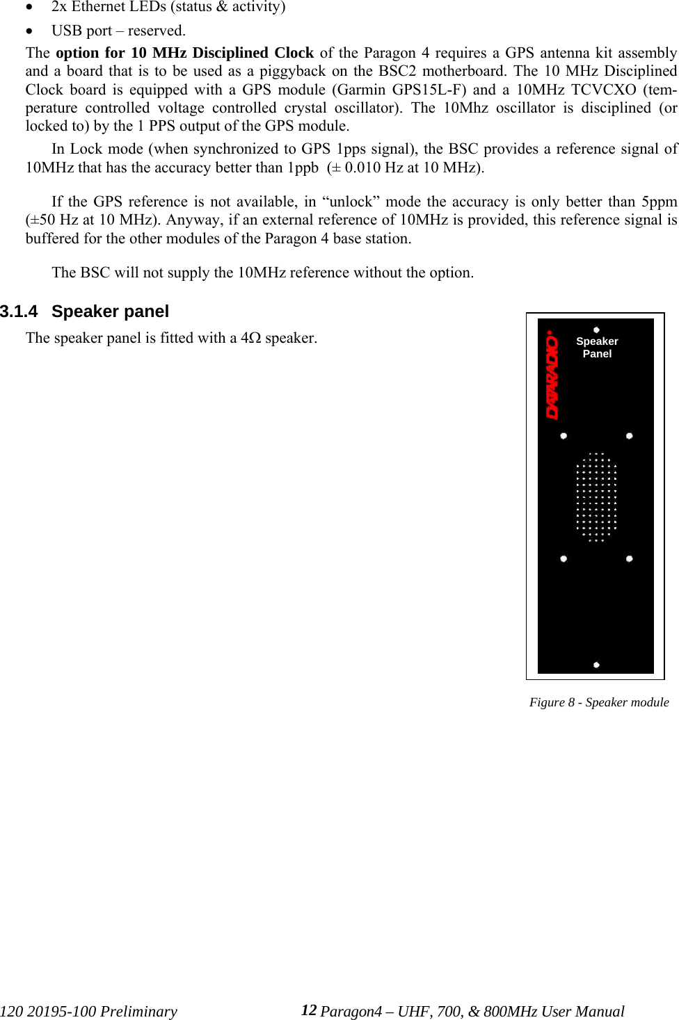
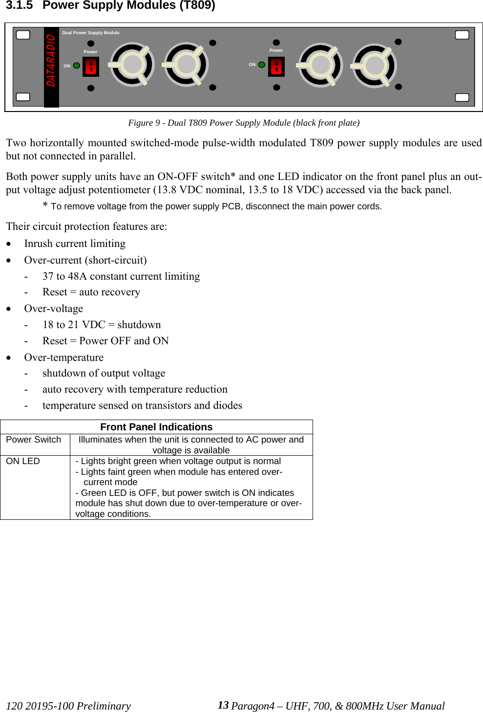
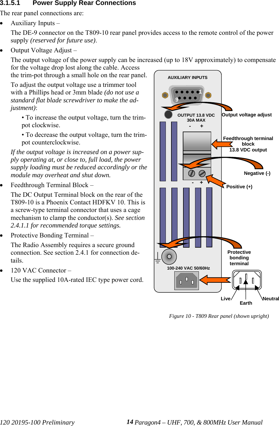
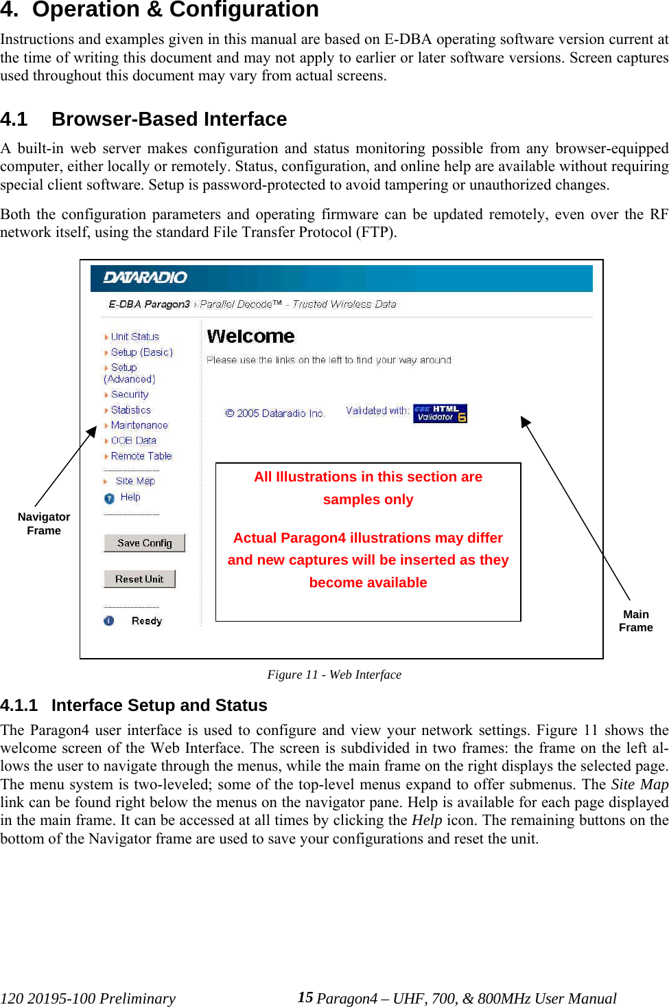
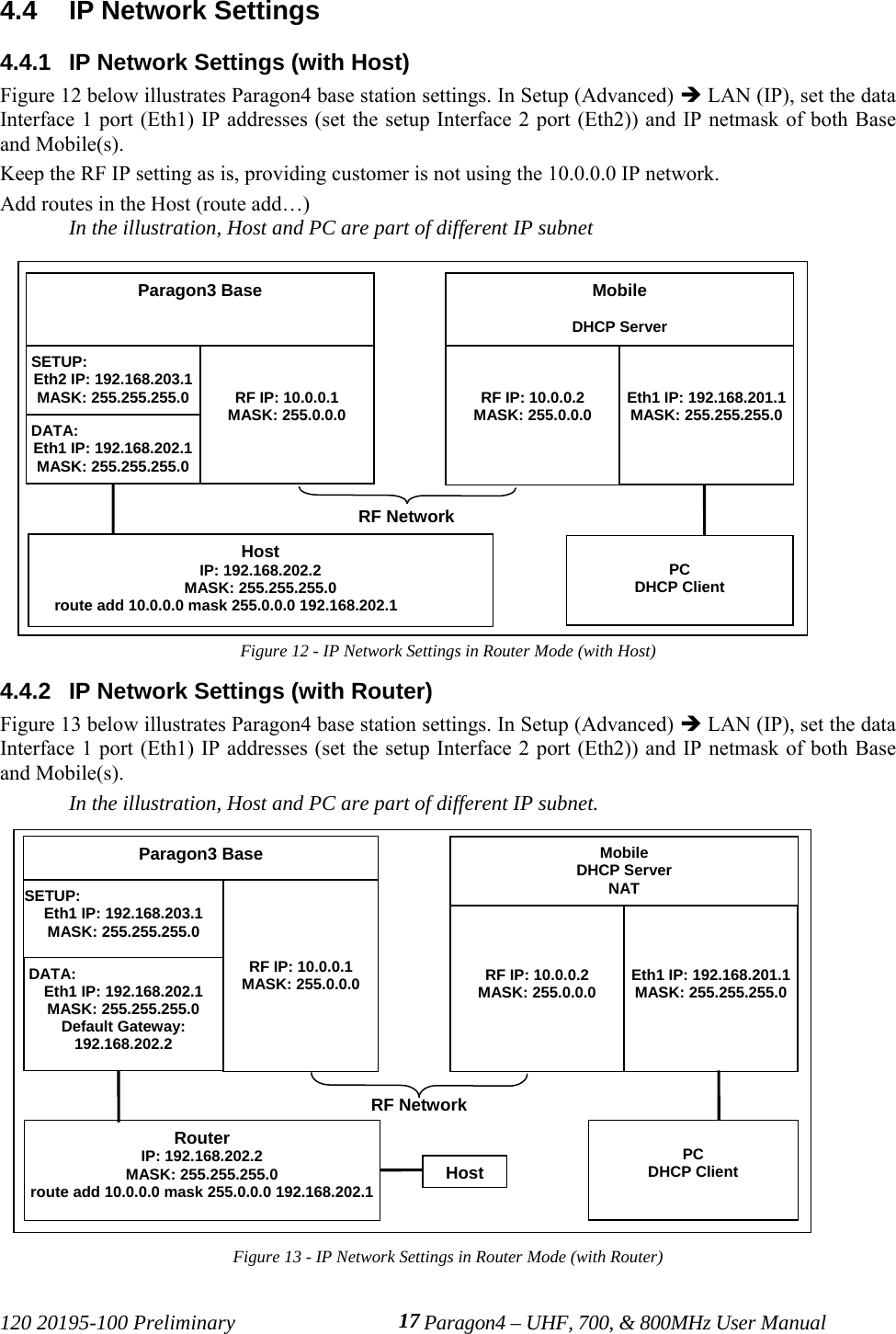
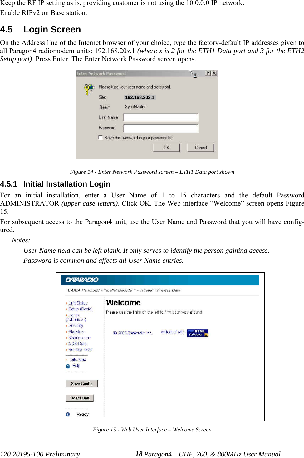
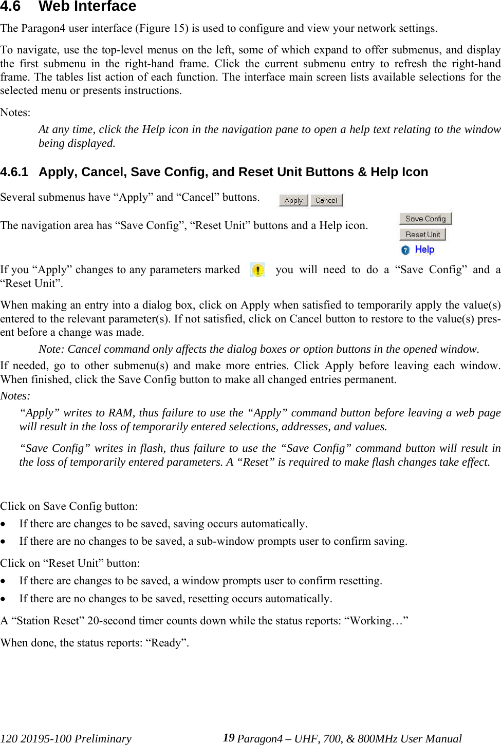
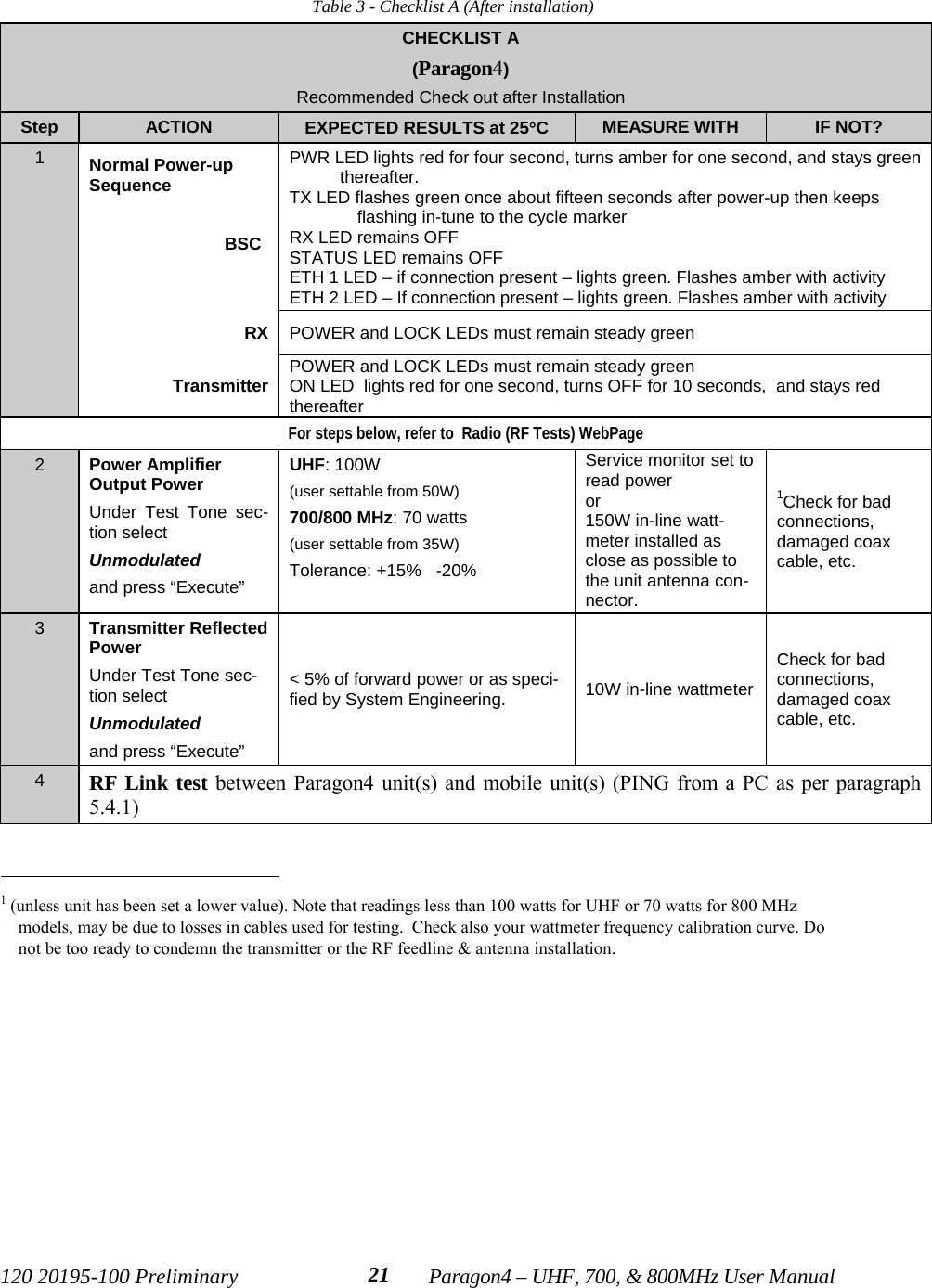
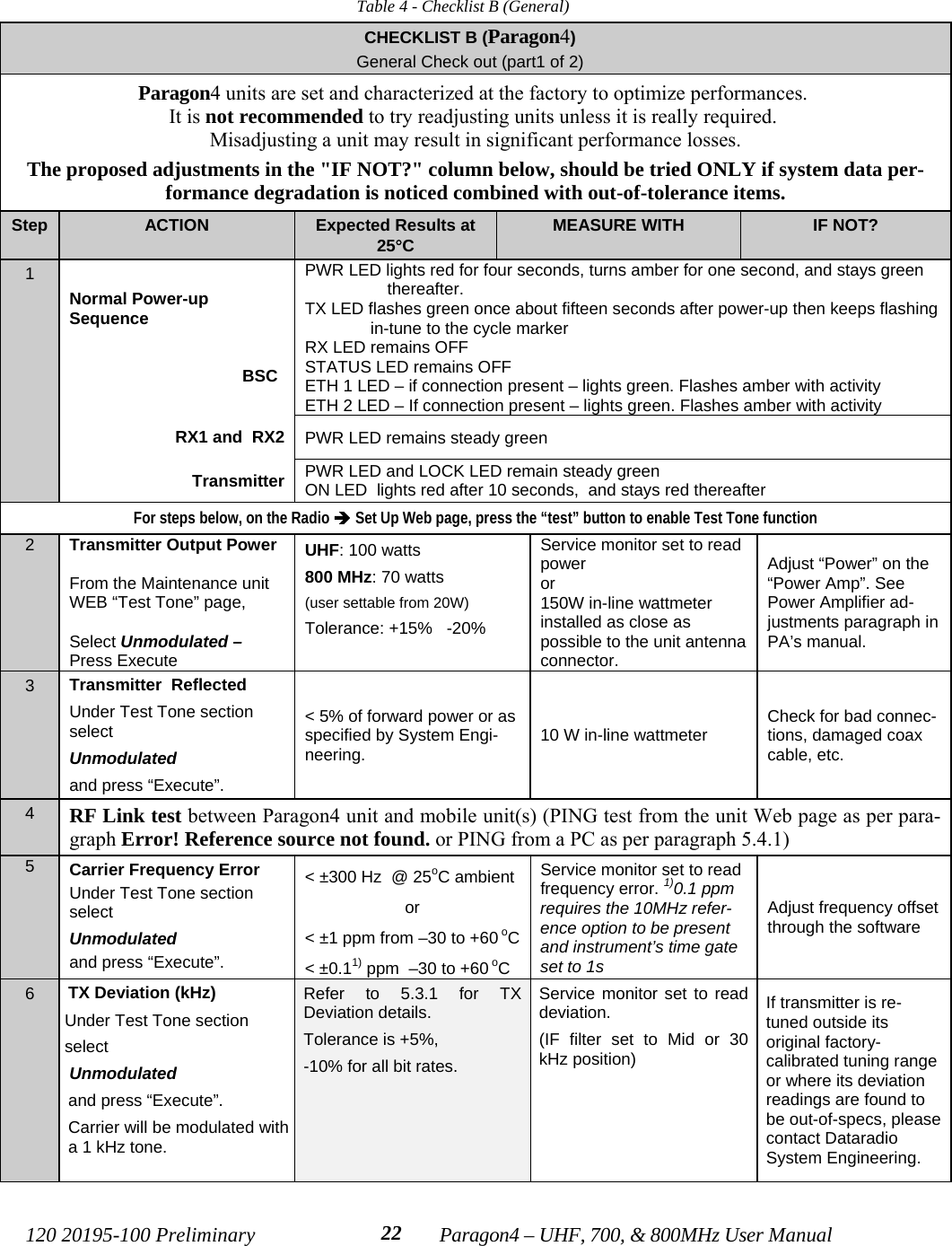
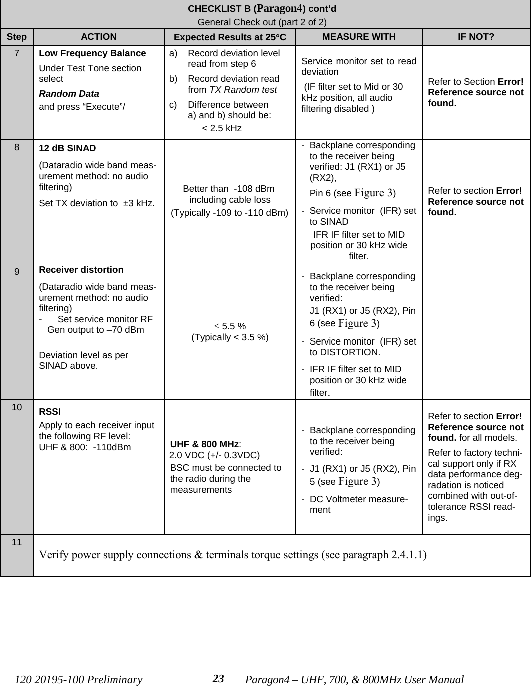
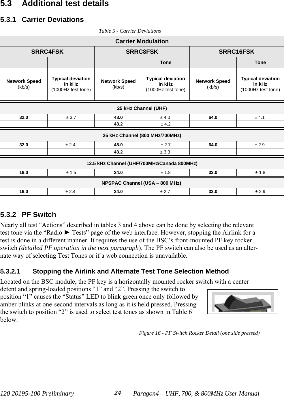
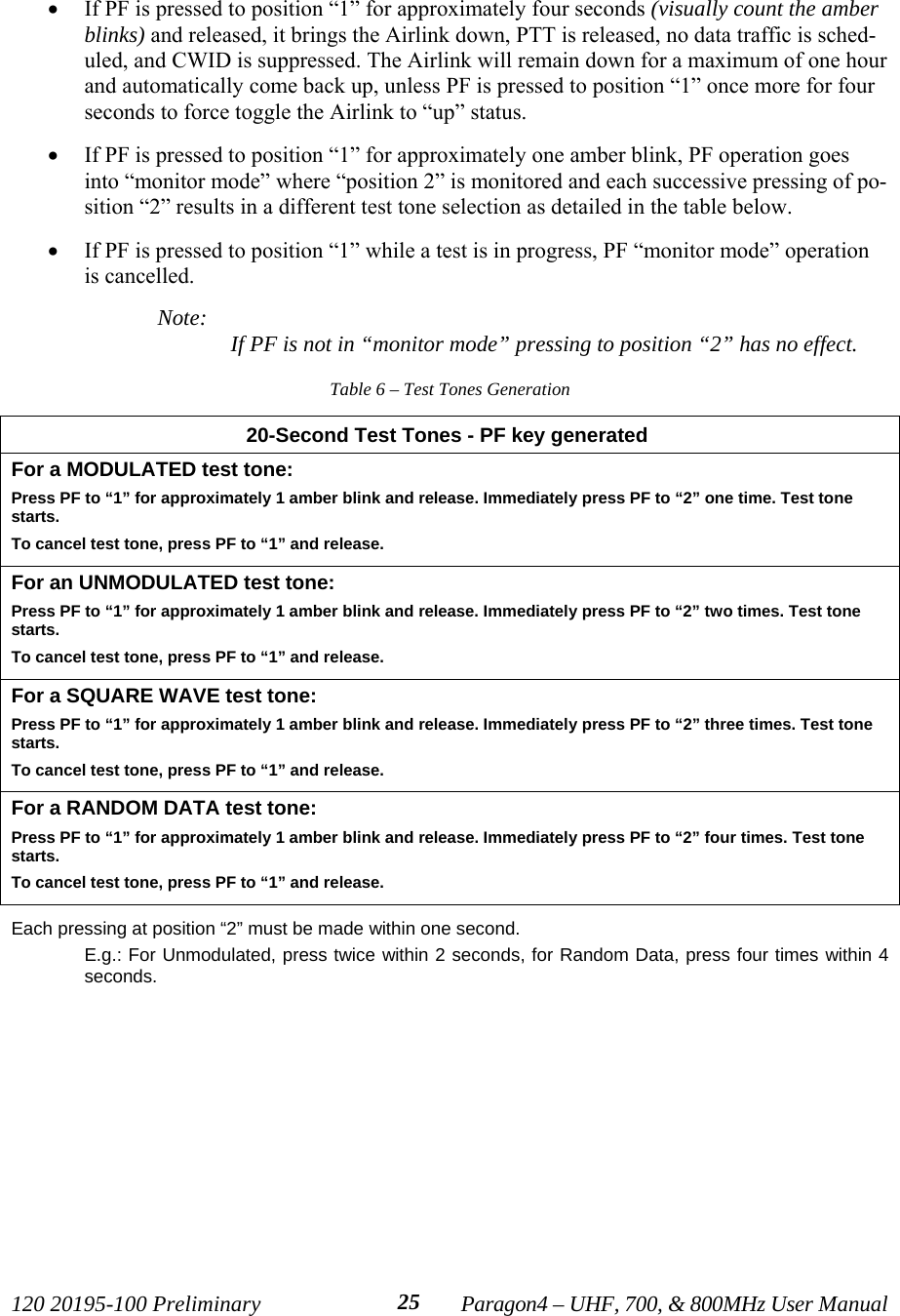
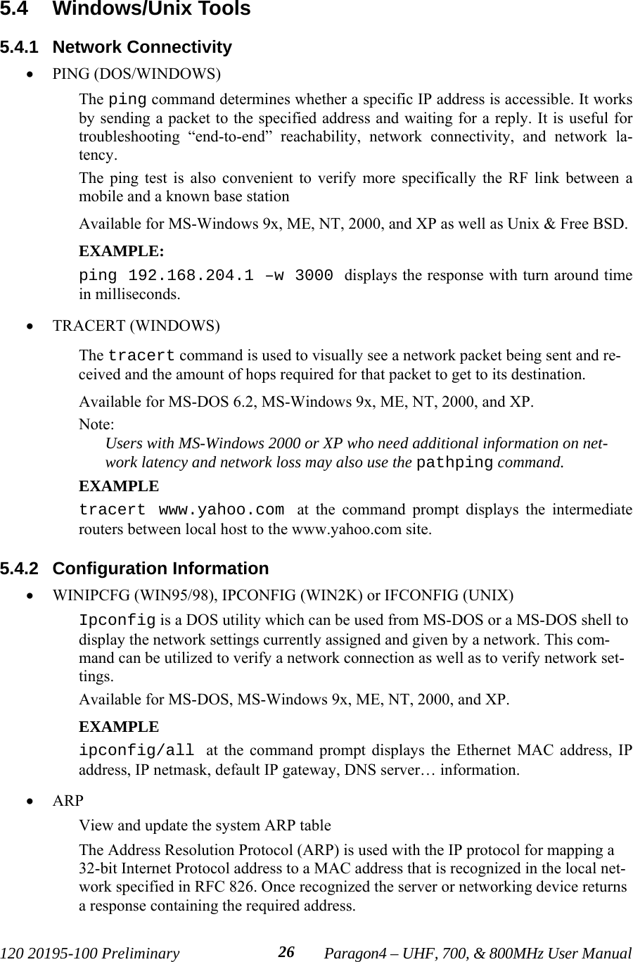
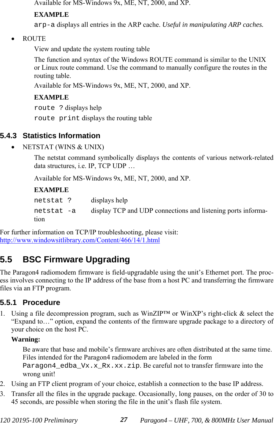
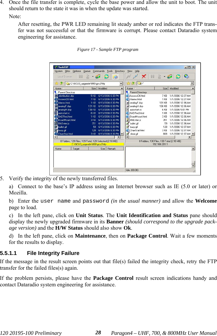
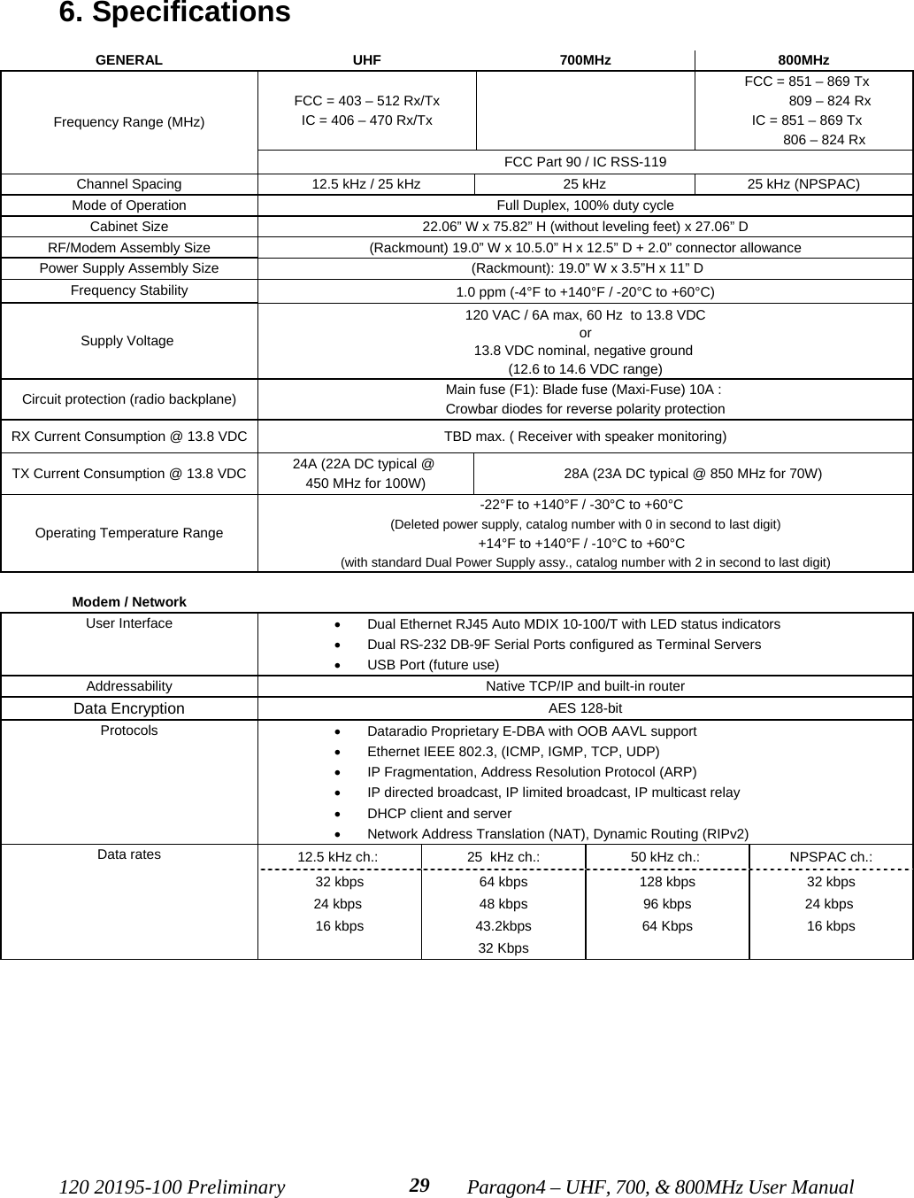
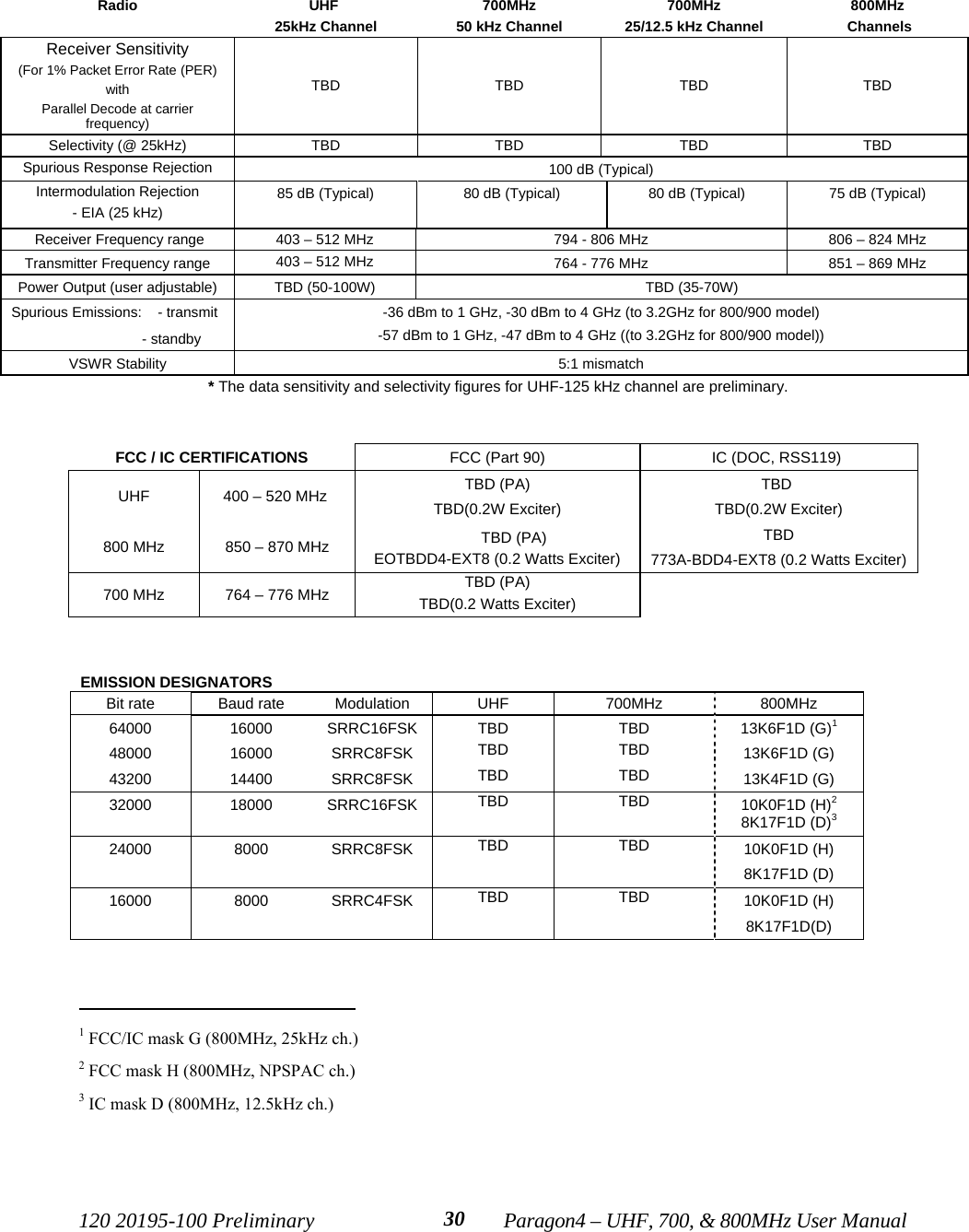
a preliminary manual for the basestation includes the exciter module

Paragon4 (UHF, 700, and 800 MHz)Data Base StationUser Manual V. 1.00Preliminary, for FCC & IC SubmissionThe entire contents of this manual are copyright 2007 by Dataradio® Inc.Copyright DATARADIO Inc.September 2007Part no.: 120 20195-100
120 20195-100 Preliminary Paragon4 – UHF, 700, & 800MHz User Manualii 1. PRODUCT OVERVIEW...................................................................................................................................11.1 INTENDED AUDIENCE....................................................................................................................................11.2 GENERAL DESCRIPTION ................................................................................................................................11.2.1 Features...................................................................................................................................................21.2.2 Configuration...........................................................................................................................................21.3 FACTORY TECHNICAL SUPPORT....................................................................................................................31.4 PRODUCT WARRANTY ..................................................................................................................................41.5 REPLACEMENT PARTS...................................................................................................................................41.5.1 Factory Repair.........................................................................................................................................41.6 PACKAGING ..................................................................................................................................................42. INSTALLATION................................................................................................................................................52.1 OVERVIEW ....................................................................................................................................................52.2 LOCATION.....................................................................................................................................................52.3 REAR VIEWS .................................................................................................................................................62.4 ELECTRICAL..................................................................................................................................................72.4.1 Standard Power Supply Configuration....................................................................................................72.4.1.1 DC Power Supply Connection & Torque Settings .......................................................................................... 72.4.1.2 Power Indications............................................................................................................................................ 82.4.2 Backplane Fuses......................................................................................................................................82.5 ANTENNA......................................................................................................................................................92.5.1 Overview..................................................................................................................................................92.5.2 Cabling and Connection..........................................................................................................................92.6 COMPLETING THE PHYSICAL INSTALLATION .................................................................................................92.7 CHECKING OUT NORMAL OPERATION...........................................................................................................93. OPERATING DESCRIPTION........................................................................................................................103.1 RADIO ASSEMBLY.......................................................................................................................................103.1.1 Receiver module.....................................................................................................................................103.1.2 Exciter module.......................................................................................................................................113.1.3 BSC module ...........................................................................................................................................113.1.4 Speaker panel.........................................................................................................................................123.1.5 Power Supply Modules (T809)...............................................................................................................133.1.5.1 Power Supply Rear Connections................................................................................................................... 144. OPERATION & CONFIGURATION ............................................................................................................154.1 BROWSER-BASED INTERFACE.....................................................................................................................154.1.1 Interface Setup and Status .....................................................................................................................154.2 LAN SETUP ................................................................................................................................................164.3 DEFAULT IP SETTINGS................................................................................................................................164.3.1 Ethernet Interface 1 (DATA)..................................................................................................................164.3.2 Ethernet Interface 2 (SETUP)................................................................................................................164.3.3 RF Interface...........................................................................................................................................164.4 IP NETWORK SETTINGS ..............................................................................................................................174.4.1 IP Network Settings (with Host) ............................................................................................................174.4.2 IP Network Settings (with Router).........................................................................................................174.5 LOGIN SCREEN............................................................................................................................................184.5.1 Initial Installation Login........................................................................................................................184.6 WEB INTERFACE .........................................................................................................................................194.6.1 Apply, Cancel, Save Config, and Reset Unit Buttons & Help Icon........................................................195. TROUBLE-SHOOTING AND TESTING......................................................................................................205.1 EQUIPMENT REQUIRED ...............................................................................................................................205.2 RECOMMENDED CHECKS ............................................................................................................................205.3 ADDITIONAL TEST DETAILS.........................................................................................................................245.3.1 Carrier Deviations.................................................................................................................................245.3.2 PF Switch...............................................................................................................................................245.3.2.1 Stopping the Airlink and Alternate Test Tone Selection Method.................................................................. 24
120 20195-100 Preliminary Paragon4 – UHF, 700, & 800MHz User Manualiii5.4 WINDOWS/UNIX TOOLS ..............................................................................................................................265.4.1 Network Connectivity.............................................................................................................................265.4.2 Configuration Information.....................................................................................................................265.4.3 Statistics Information.............................................................................................................................275.5 BSC FIRMWARE UPGRADING .....................................................................................................................275.5.1 Procedure ..............................................................................................................................................275.5.1.1 File Integrity Failure ..................................................................................................................................... 286. SPECIFICATIONS ..........................................................................................................................................29FIGURE 1 - FRONT VIEW "RADIO ASSEMBLY" ................................................................................................................5FIGURE 2 - PARAGON4 UNIT REAR VIEW ........................................................................................................................6FIGURE 3 - BACKPLANE .................................................................................................................................................6FIGURE 4 - MAXI-FUSE ..................................................................................................................................................8FIGURE 5 - RECEIVER MODULE.....................................................................................................................................10FIGURE 6 - EXCITER MODULE.......................................................................................................................................11FIGURE 7 - BSC MODULE .............................................................................................................................................11FIGURE 8 - SPEAKER MODULE ......................................................................................................................................12FIGURE 9 - DUAL T809 POWER SUPPLY MODULE (BLACK FRONT PLATE)....................................................................13FIGURE 10 - T809 REAR PANEL (SHOWN UPRIGHT) ......................................................................................................14FIGURE 11 - WEB INTERFACE.......................................................................................................................................15FIGURE 12 - IP NETWORK SETTINGS IN ROUTER MODE (WITH HOST) .........................................................................17FIGURE 13 - IP NETWORK SETTINGS IN ROUTER MODE (WITH ROUTER) .....................................................................17FIGURE 14 - ENTER NETWORK PASSWORD SCREEN – ETH1 DATA PORT SHOWN ........................................................18FIGURE 15 - WEB USER INTERFACE – WELCOME SCREEN ...........................................................................................18FIGURE 16 - PF SWITCH ROCKER DETAIL (ONE SIDE PRESSED)....................................................................................24FIGURE 16 - SAMPLE FTP PROGRAM............................................................................................................................28TABLE 1 - ON-AIR DATA SPEEDS AND MODULATION ......................................................................................................2TABLE 2 - TEST POINTS..................................................................................................................................................6TABLE 3 - CHECKLIST A (AFTER INSTALLATION) ........................................................................................................21TABLE 4 - CHECKLIST B (GENERAL)............................................................................................................................22TABLE 5 - CARRIER DEVIATIONS .................................................................................................................................24TABLE 6 – TEST TONES GENERATION ..........................................................................................................................25
120 20195-100 Preliminary Paragon4 – UHF, 700, & 800MHz User ManualivWHAT'S NEW HistoryVersion 1.00: November 2007 – For FCC and IC Submission• Initial preliminary of Paragon4 base station User Manual forUHF, 700 / 800 MHz radio modem models.
120 20195-100 Preliminary Paragon4 – UHF, 700, & 800MHz User ManualvAbout DataradioFor over 25 years, Dataradio has been a recognized and innovative supplier of advanced wireless dataproducts and systems for mission-critical applications. Public safety organizations, utilities, local gov-ernment, water management, and other critical infrastructure operations depend on Dataradio to ensurethat vital wireless data reaches the people who need it, when they need it most. From mobile data systemsand radio modems, to analog radios and telemetry devices, Dataradio products are found at the heart ofprivate wireless networks around the world. www.dataradio.comDataradio provides product brochures, case studies, software downloads, and product information on ourwebsite at http://www.dataradio.com User Manual StatementEvery effort is taken to provide accurate, timely product information in this user manual. Product updates may result in differences between the information provided herein and the productshipped. The information in this document is subject to change without notice.About CalAmp Corp.CalAmp is a leading provider of wireless equipment, engineering services and software that enable any-time/anywhere access to critical information, data and entertainment content. With comprehensive capa-bilities ranging from product design and development through volume production, CalAmp delivers cost-effective high quality solutions to a broad array of customers and end markets. CalAmp is the leadingsupplier of Direct Broadcast Satellite (DBS) outdoor customer premise equipment to the U.S. satellitetelevision market. The Company also provides wireless connectivity solutions for the telemetry and assettracking markets, public safety communications, the healthcare industry, and digital multimedia deliveryapplications. www.CalAmp.comFor additional information, please visit http://www.calamp.com   DATARADIO and VIS are registered trademarks,GeminiG3, Paragon4, PARALLEL DECODE, and TRUSTED WIRELESS DATA are trademarks of Dataradio Inc
120 20195-100 Preliminary Paragon4 – UHF, 700, & 800MHz User ManualviDefinitions  Access Point Communication hub for users to connect to a wired LAN. APs are important forproviding heightened wireless security. ADB Agile Dual-Band - GeminiG3 radiomodem model that allows 700/800MHzautomatic band switching capability during roaming.AES Advanced Encryption Standard (AES) - uses 128-bit encryption to secure data.Airlink Physical radio frequency connections used for communications between units.ARP Address Resolution Protocol – Maps Internet address to physical address. AAVL Autonomous Automatic Vehicle Location. Optional feature that involves usingGPS (Global Positioning System) signals from the mobile unit by the Host PC. Backbone  The part of a network that connects most of the systems and networks together,and handles the most data.Bandwidth  The transmission capacity of a given device or network. Base Designates products used as base stations in VIS systems. They currently includethe Paragon family of products up to the Paragon4 radiomodems. Browser  An application program that provides a way to look at and interact with all the in-formation on the World Wide Web. BSC Base Station Controller - An async controller-modem designed for the radio basestation in mobile systems. A component of Paragon4 radiomodem base stations. COM Port RS-232 serial communications ports of the Paragon4 wireless radiomodem. Cycle Mark  Signal transmitted on an E-DBA network that keeps the network synchronized. Default Gateway  A device that forwards Internet traffic from your local area network.DHCP  Dynamic Host Configuration Protocol - A networking protocol that allows ad-ministrators to assign temporary IP addresses to network computers by "leasing"an IP address to a user for a limited amount of time, instead of assigning perma-nent IP addresses.DNS  Domain Name Server - The on-line distributed database system used to map hu-man-readable machine names into IP addresses.Domain  A specific name for a network of computers.Dynamic IP Addr A temporary IP address assigned by a DHCP server. E-DBA Enhanced Dynamic Bandwidth Allocation – Dataradio proprietary protocol thatschedules all inbound and outbound Airlink traffic to minimize contention.Ethernet  Ethernet is a frame-based computer networking technology for local area net-works (LANs). It defines wiring and signaling for the physical layer, and frameformats and protocols for the media access control (MAC)/data link layer of theOSI model. Ethernet is mostly standardized as IEEEs 802.3.Feature Key Method used to implement customer’s option(s) selected at the time of radiomo-dem purchase (factory-installation) or as add-on (field-installation).Firewall  A set of related programs located at a network gateway server that protects theresources of a network from users from other networks.Firmware  The programming code that runs a networking device.Fragmentation Breaking a packet into smaller units when transmitting over a network mediumthat cannot support the original size of the packet.FTP  File Transfer Protocol - A protocol used to transfer files over a TCP/IP network.
120 20195-100 Preliminary Paragon4 – UHF, 700, & 800MHz User ManualviiGateway  A device that interconnects two or more networks with different, incompatiblecommunications protocols and translates among them. GeminiG3 Third generation of GeminiPD VIS products. High specs dual DSP mobile radio-modem with Dataradio Parallel Decode™ technology  HDX Half Duplex. Data transmission that can occur in two directions over a singleline, using separate Tx and Rx frequencies, but only one direction at a time.HTTP  HyperText Transport Protocol - The communications protocol used to connect toservers on the World Wide Web.IPCONFIG  A Windows 2000 and XP utility that displays the IP address for a particular net-working device.MAC  ADDRESS Media Access Control - The unique address that a manufacturer assigns to eachnetworking device.MIB  Management Information Base (MIB)-a logical, hierarchically organized data-base of network management information. Used in SNMP.NAT  Network Address Translation - NAT technology translates IP addresses of a localarea network to a different IP address for the Internet.Network  A series of computers or devices connected for the purpose of data sharing, stor-age, and/or transmission between users.Network speed This is the bit rate on the RF link between units. Node  A network junction or connection point, typically a computer or work station.OID An object identifier or OID is an identifier used to name an object and is the nu-merical equivalent of a path. In SNMP, an OID consists of numbers separated bydecimal points. Structurally, an OID consists of a node in a hierarchically as-signed namespace.OIP Optimized IP – Compresses TCP and UDP headers, and filters unnecessary ac-knowledgments. This makes the most use of the available bandwidth.OTA Over-The-Air - Standard for the transmission and reception of application-relatedinformation in a wireless communications systemPalette  Synchronization patterns used to identify the speed and coding of packets trans-mitted over-the-air in E-DBA.Paragon4 IP-based data radio base station used in mobile networks and designed specifi-cally to fit the needs of vehicular applications. Runs up to 128 kb/s Parallel Decode Technology featuring dual receivers for added data decode sensitivity in multi-path and fading environments. (United States Patent No: 6,853,694 B1)PHY A PHY chip (called PHYceiver) provides interface to the Ethernet transmissionmedium. Its purpose is digital access of the modulated link (usually used togetherwith an MII-chip). The PHY defines data rates and transmission method parameters. PDU Protocol Data Unit - A PDU is a message of a given protocol comprising payloadand protocol-specific control information, typically contained in a header. PDUspass over the protocol interfaces that exist between the layers of protocols.Ping  Packet INternet Groper - An Internet utility used to determine whether a particu-lar IP address is online.PLC Programmable Logic Controller. An user-provided intelligent device that canmake decisions, gather and report information, and control other devices.Roaming Movement of a wireless node (GeminiG3 radiomodems) amongst Multiple Ac-cess Points (Paragon4). Paragon4 radiomodems support seamless roaming.Router  A networking device that connects multiple networks together.
120 20195-100 Preliminary Paragon4 – UHF, 700, & 800MHz User Manualviii RS-232 Industry–standard interface for data transfer. Smart Combining Digital processing method used to combine “Spatial Diversity” signals to opti-mize performance. (See Parallel Decode)SNMP  Simple Network Management Protocol - Provides a means to monitor and con-trol network devices, and to manage configurations, statistics collection, per-formance, and security.Spatial Diversity Composite information from independent diversity branches using antennasspaced apart is used with “Smart Combining” to minimize fading and other unde-sirable effects of multipath propagation. (See Parallel Decode)SRRCnFSK Square Root Raised Cosine (n = level) Frequency Shift Keying. Type of fre-quency modulation of data signals performed by the Paragon4 radiomodem.Static IP Address  A fixed address assigned to a computer or device that is connected to a network.Static Routing  Forwarding data in a network via a fixed path.Subnet Mask  A bit mask used to select the bits from an IP address that correspond to the sub-net. Each mask is 32 bits long, with one bits in the portion that identifies a net-work and zero bits in the portion that identifies a host.Switch (Ethernet) Computer-networking device that allows sharing a limited number of ports toconnect computing devices to host computers. Replaces network hubs (layer1),switches (layer2), routers (layer3). Sync  Data transmitted on a wireless network that keeps the network synchronized. TCP/IP  Transmission Control Protocol/Internet Protocol - A transport (layer4) protocolfor transmitting data that requires acknowledgement from the recipient of datasent. Handles retries and flow control.Telnet  Network (layer5) protocol used on the Internet or on LAN connections.TFTP  Trivial File Transfer Protocol - A version of the TCP/IP FTP protocol that has nodirectory or password capability.Topology  The physical layout of a network.Transparent A transparent unit transmits all data without regard to special characters, etc.UDP  User Datagram Protocol - A transport (layer4) protocol for transmitting data thatdoes not require acknowledgement from the recipient of the data that is sent.Upgrade  To replace existing software or firmware with a newer version.URL  Universal Resource Locator - The address of a file located on the Internet. VIS Vehicular Information Solutions. Dataradio’s name for a series of products spe-cially designed for mobile data.WINIPCFG  A Windows 98 and Me utility that displays the IP address for a particular net-working device. WLAN  Wireless Local Area Network - A group of computers and associated devices thatcommunicate with each other wirelessly.
120 20195-100 Preliminary Paragon4 – UHF, 700, & 800MHz User Manual11. PRODUCT OVERVIEWThis document provides information required for the setting up, operation, testing and trouble-shooting ofthe Dataradio® Paragon4™ radio-modem base station. 1.1  Intended AudienceThis document is intended for engineering, installation, and maintenance personnel.1.2  General DescriptionThe Paragon4 radio base station is a factory-integrated industrial-grade IP-based data product used in mobilenetworks and is designed specifically to fit the needs of vehicular applications. It features dual receivers foradded data decode sensitivity in multi-path and fading environments.When used with Dataradio’s state-of-the-art GeminiG3 mobile IP data solution, the system deliversunequaled high-speed data performance and unmatched effective throughput. All Paragon4 models are supplied in a standard 19-inch wide rackmount. The Paragon4 full-duplex radio-modem chassis assembly includes:• A second generation high-speed Dataradio “Base Station Controller” module (BSC2) that uses an openarchitecture that simplifies the implementation process. The BSC2 module comes equipped with a built-in IP router with dual Ethernet 10/100 BaseT interfaces. • Option for 10MHz reference source input• Dual, independently synthesized Receiver radio module.• High-performance synthesized 0.2W Exciter radio module.For all Paragon4 radio modem units:• One Power Amplifier (PA) module is required for the regular usage.    • Duplexer and backup power units are custom furnished items. • Wire line modem(s) are optional items. • Laptop PC and its application software are user-supplied items.• Optional Router – Add a second router anywhere within your network if you need a fault tolerantnetwork.
120 20195-100 Preliminary Paragon4 – UHF, 700, & 800MHz User Manual21.2.1  Features• Parallel Decode™ technology featuring dual receivers for added decode sensitivity in multi-pathand fading environments.• Fully IP-based product models, using an optimized IP layer that reduces IP overhead for the RFlink• Sophisticated dual DSP-based modem design provides added system performance, fewer retriesand more effective throughput.• Full duplex mode of operation • Base Station with an RF Power Amplifier. The Power Amplifier is considered a stand-alonemodule. • On-air data speeds and modulation types supported (dependent on “Feature Key” selected1):Table 1 - On-air data speeds and modulationChannel TypeUHF 700 MHz / 800 MHzModulationtype 25 kHz 12.5 kHz 50 kHz 25 kHz 12.5 kHz  NPSPACSRC16FSK 64 kb/s 32 kb/s 128 kb/s 64 kb/s  32kb/s 32kb/sSRC8FSK 48 kb/s43.2 kb/s 24 kb/s  96kb/s  48kb/s43.2kb/s  24kb/s 24kb/sSRC4FSK 32 kb/s 16 kb/s  64kb/s 32 kb/s  16kb/s 16kb/s• Uses Dataradio’s Next generation high-efficiency Enhanced-DBA (E-DBA) over-the-airprotocol• Over-the-air compatible with GeminiG3.x mobile products• Out-of-band signaling enables transmission of GPS reports with no effect on systemperformance.• Flash programmable firmware, including over-the-air programming capability 1.2.2  ConfigurationParagon4 units are factory-configured. Configuration changes or upgrades are web-based.                                           1 Method used to implement customer’s option(s) selected at the time of radiomodem purchase (factory-installation) or as add-on(field-installation).
120 20195-100 Preliminary Paragon4 – UHF, 700, & 800MHz User Manual31.3  Factory Technical Support The Technical Support departments of DATARADIO provide customer assistance on technical prob-lems and serve as an interface with factory repair facilities. They can be reached in the followingways: For Canada and International customers: DATARADIO Inc. 5500 Royalmount Ave, suite 200 Town of Mount Royal Quebec, Canada H4P 1H7 Technical support hours: Monday to Friday 9:00 AM to 5:00 PM, Eastern Time phone: +1 514 737-0020fax: +1 514 737-7883 Email address: support@dataradio.com or For U.S. customers:  DATARADIO Corp. 6160 Peachtree Dunwoody RD., suite C-200 Atlanta, Georgia 30328 Technical support hours: Monday to Friday 9:00 AM to 5:00 PM, Eastern Time phone: 1 770 392-0002 fax: 1 770 392-9199 Email address: drctech@dataradio.com
120 20195-100 Preliminary Paragon4 – UHF, 700, & 800MHz User Manual41.4  Product Warranty Warranty information may be obtained by contacting your sales representative.1.5  Replacement Parts This product is usually not field-serviceable, except by the replacement of individual radio modules.Specialized equipment and training is required to repair logic, modem boards, and radio modules. Contact Technical Support for service information before returning equipment. A Technical Supportrepresentative may suggest a solution eliminating the need to return equipment.1.5.1  Factory Repair When returning equipment for repair, you must request an RMA (Returned Material Authorization)number. The Tech Support representative will ask you several questions to clearly identify the prob-lem. Please give the representative the name of a contact person, who is familiar with the problem,should a question arise during servicing of the unit. Customers are responsible for shipping charges for returned units. Units in warranty will be repairedfree of charge unless there is evidence of abuse or damage beyond the terms of the warranty. Unitsout of warranty will be subject to service charges. Information about these charges is available fromTechnical Support.1.6  PackagingEach Paragon4 radio-modem base station – UHF, 700 MHz, or 800MHz  – normally leaves the factorypackaged as follows:• A Dataradio base station “Radio-modem assembly” with dual power supply assembly, and aBSC.• Two standard seven-foot 120 VAC power cords. • Coax cable (16-inch) to connect the Exciter module to the power amplifier.Frequently, Paragon4 product components are field-assembled prior to customer delivery. The cabinetry may then be supplied in one of several custom rack-mount configurations that may also in-clude fan, backhaul modems, duplexer/filters/combiners, and ancillary equipment. If damage has occurred to the equipment during shipment, file a claim with the carrier immediately.
120 20195-100 Preliminary Paragon4 – UHF, 700, & 800MHz User Manual52. InstallationFigure 1 - Front view "Radio Assembly"2.1  OverviewThe cabinet and rack-mount housing the Paragon4’s radio-modem and Power Amplifier is generallyinstalled in a sheltered facility. Occasionally located adjacent to the nerve center of the user’snetwork, it is often located near tower sites or at remote locations where it operates unattended.Furnishings needed include power, cabling, and installation of antenna, landline or microwave mo-dem, and host PC or portable computer. Details of these are outside the scope of this manual. Thismanual covers the radio-modem assembly. The power amplifier has its own user manual that is in-corporated by reference at the moment of the order.2.2  LocationBe sure to place the Paragon4 unit in such a way that:• The LEDs can be seen (as an aid in troubleshooting)• Access to the antenna connector and to the back connectors is possible without removing the unit • Sufficient air may flow around the unit to provide adequate cooling.
120 20195-100 Preliminary Paragon4 – UHF, 700, & 800MHz User Manual62.3  Rear ViewsFigure 2 - Paragon4 unit rear viewFigure 3 - BackplaneTable 2 - Test PointsBackplane Test Points Rx/TxTest J9 Access port Alternate PinoutGround  Pin 14 J18, J19 – Pin 3SINAD &Distorsion RX1 -Differential 1P-3; 1N-8 J18- Pins 1,2SINAD &Distorsion RX2-Differential 2P-4; 2N-9 J19 – Pins 1,2RSSI RSSI 1 -Differential 1P-1; 1N-6 J18 – Pins 4,5RSSI RSSI 2-Differential 2P-2; 2N-7 J19 – Pins 4,5      .10-amp fuse J18Access  portJ9 J19RX 1&2BSCExciterSpeaker Panel
120 20195-100 Preliminary Paragon4 – UHF, 700, & 800MHz User Manual72.4  ElectricalStandard 120 VAC electrical power is required. It should be capable of providing at least 10A topower Paragon4 unit (<6A) and ancillary equipment.2.4.1  Standard Power Supply ConfigurationAlthough the T809-10 is a high efficiency switched mode power supply, a considerableamount of heat is generated during normal operation. While in use, ensure that an adequateflow of cooling air is able to circulate around the power supply, and that the air intake ventson the rear and sides of the unit are not inadvertently covered.Caution:Do not operate this unit in a completely enclosed cabinet.The Radio assembly unit receives 13.8 VDC power inputs from two “T809 ” power supply modulespowered at 120 VAC. Normally used at room ambient temperatures, it can operate within its specifi-cations over a range of –10 to +60 °C.Note: Internal over-temperature protection shuts down the main transformer above 105° Celsius.Both power supply modules are internally connected to ground via their individual, rear-connected,seven-foot standard 120 VAC power cords. The Radio Assembly chassis requires a secure groundconnection. A threaded grounding binding post fitted with a knurled binding-nut is provided on thechassis next to DC input 2. • For the Radio Assembly chassis, install the grounding lead’s lug over the binding post and firmlyhand-tighten the binding-nut.• If a –DC rail (0V) is installed as part of the system, the grounding leads may alternatively be fit-ted to the rail terminal.Caution:Improper grounding between power supply case and rack frame may result in harmful voltage poten-tials and/or miscellaneous power supply switching noise problems in both receivers and transmitter.2.4.1.1  DC Power Supply Connection & Torque SettingsWarning:Securing the DC Power Supply cable into the DC connector to provide a good electrical con-nection is essential. Over time, the wires tend to compress in the DC connector resulting in anincreasingly poorer connection. Consequently, as high current is drawn, the connector heats upincreasing the resistance thereby causing still more heat until the connector eventually burns up. Although screws securing DC cables to the Power Supply terminals are tightened to the torque set-tings given below prior to new system delivery, they must be re-tightened as part of the commission-ing process and re-tightening is also part of the regular maintenance schedule.Prior to replacing a Power Supply module into an existing system, inspect the cable and re-terminatethe DC wires if the strands have previously been twisted together or show any sign of damage.Cut the wire at the end of the insulation and then strip approximately .43 inch (11mm) of insulationoff the cable. DO NOT TWIST THE WIRE STRANDS. Insert the DC cable into the screw terminaland tighten the screw to secure the cable as per the torque settings given below.
120 20195-100 Preliminary Paragon4 – UHF, 700, & 800MHz User Manual8Torque Settings: The manufacturer recommends torque setting all power supply terminal screws to a minimum of:• 1.5 Nm (or 13.28 Inlb or to 1.107 ftlb)Note: Dataradio uses a Sturtuvan Richmond 29-pieces adjustable torque screwdriver modelCAL36/4K.After tightening, pull on the cable to check the cable is secured tightly into the screw terminal.2.4.1.2  Power IndicationsBoth red-colored translucent power switches located on the front of the power supply modules illu-minate when AC power is available. Toggle both to ON to distribute power to the Radio Assemblyand to the Power Amplifier. The LED immediately below the switches light green indicating normalDC power operation. 2.4.2  Backplane FusesBlade fuses (Maxi-Fuse) are used on the Radio assembly backplane:Dimensions – Inch (mm)Fuse Type ABCMaxi-Fuse 1.15 (29.21) 1.35 (34.29) .35 (8.89)Fuse # F1 F2 F3Values 10A 15A* 15A** Always replace the two 15A fuses as a pair.Figure 4 - Maxi-Fuse
120 20195-100 Preliminary Paragon4 – UHF, 700, & 800MHz User Manual92.5  Antenna2.5.1  OverviewThe Paragon4 unit commonly uses three antennas (one transmit and two receive) unless a duplexer isused with one of the receive antennas; then only two antennas would be needed. If the 10MHz Disci-plined Clock option is sought, there is another GPS antenna is adittion to the three already mentioned.They should be mounted according to any guidelines supplied with the antennas. For antennas place-ment and spacing, consult System Engineering. 2.5.2  Cabling and Connection1- Route good quality 50-ohm double-shielded coaxial cable(s) (e.g. RG-214 or Heliax) from theselected antenna position(s) to the Paragon4 Radio assembly.2- Referring to Figure 2 for locating modules, terminate the RX-1 and RX-2 cable-ends at their re-spective module rear position with N-type connectors.3- Similarly, terminate the TX cable-end at the rear position of the Power Amp’s module with anN-type connector.Caution: When terminating RF cables use brand-name crimping tools (such as AMP, Jensen,Crimp-Master, etc…) of the correct size for the cable and type of connector used.Common pliers are NOT acceptable.2.6  Completing the physical InstallationParagon4 products are factory-configured to user’s requirements and are shipped ready to run. After new installations:• Re-check that all connections are secure on the radio-modem assemblies (antennas, PC, powercords etc.)• Check that fuses are inserted.• Turn power supplies ON.You are now ready to check for normal operation (as per paragraph 2.7) and to run the Dataradio webinterface (described in section 4) for testing or trouble-shooting. Any change(s) to the settings must be done via files saved on diskette and loaded into the unit usingthe web interface program.2.7  Checking out Normal Operation1- Check that power is applied.2- Check Radio assembly lights for proper operation as per section 3.13- Check for proper operation of the BSCs LEDs.4- Using the web interface program and an in-line wattmeter, check forward & reverse power toconfirm main antenna installation.5- Using the web interface, check the RF Data Link with a mobile that can be heard.If user application and mobiles are available, test the installation by going through a normal sequenceof transmitting and receiving messages.
120 20195-100 Preliminary Paragon4 – UHF, 700, & 800MHz User Manual103. Operating Description3.1  Radio Assembly The Radio assembly component of each Paragon4 product – UHF, 700, and 800MHz – is made up ofhigh performance synthesized radio base station designed for single operation. The Radio Assembly’smodules are commonly installed in a standard, 19-inch wide rack frame. The complement of modules is:• 1 x Receiver module• 1 x Exciter module• 1 x BSC (controller-modem)• 1 x Speaker paneland mounted on the rack (normally immediately below the Paragon4 radiomodem):• 1 x Dual Power Supply module3.1.1  Receiver moduleFor locating the module, refer to Figure 2 above. The receiver has several front panel controls and indicators. These are:• LEDs -Four LEDs as for the SDR-Rx receiver module:Green  normal operationAmber  bootloader program runningPWR LEDRed  malfunction / resetGreen  PLL lockedLOCKLED Red          PLL not lockedGreen  RF carrier signal on audio channel 1 is above manu-ally adjusted mute threshold1 LED Off  RF carrier signal on audio channel 1 is below manuallyadjusted mute thresholdGreen  RF carrier signal on audio channel 2 is above manu-ally adjusted mute threshold2 LED Off  RF carrier signal on audio channel 2 is below manuallyadjusted mute threshold• RCVR GATE LEVEL  - Mute threshold adjustment. It sets the RF signallevel required to open the mute gate and allow audio to pass to thespeaker1.• 1 / 2 Switch – Manual selection of Channel 1 or 2 audioFigure 5 - Receiver module• Volume - The audio output delivers up to 1 watt to the speaker. Always set volume knob tominimum when not in use to reduce current consumption.• NORM-MON Switch – Manual selection between audio unmuted (continuous monitor) or whenaudio is above the manually adjusted mute threshold LOCK  PWR RCVR GATELEVELVOLUME NORM -DiversitySDR Rx
120 20195-100 Preliminary Paragon4 – UHF, 700, & 800MHz User Manual113.1.2  Exciter moduleThe Exciter’s front panel controls and indicators are:• Carrier test - momentarily keys the transmitter ON while pressed (used fortest purposes only). If the Carrier is pressed for 4 seconds or more the ex-citer starts the test mode and keeps transmitting until the next press of thebutton.• LED indicators, according to the table below.• one DE-9 RS-232 ports for setup.  Figure 6 - Exciter module3.1.3  BSC moduleThe BSC2's front panel connectors and indicators are:Green  Normal operationAmber  Step 2 in uMon boot-up – lights for <1 sec.Red  Step 1 in uMon boot-up – lights for <1 sec.PWRLED RedflashingHardware error, must check the log files toidentify itGreen  Flashes for each data packets receivedRX LED Red          Discard RX packet (factory-use)Green  Flashes for each data packets transmittedAmber Flashes for each data packets transmitted (check for lost Host connection)RedContinuoulsy ON for TXON test (max. 20secs.)Flashes ON for CWID key-up eventTX LEDOff  Check if in “AirLink down mode”Green  Flashes each time PF1 or PF2 is pressedSTATUS AmberFlashes each second PF1 is kept pressed Toggles “AirLink down mode” after 4 sec-onds• 2x DE-9 RS-232 ports for setup and user dataFigure 7 - BSC module• 1x rocker switch (positions PF 1 and 2) to select various test modes. See paragraph 5.3.2. • 2x Ethernet ports – for setup and user dataGreen Red flashingAmber OffPower normal Fault 1 (TBD) fault 2 (TBD)TX transmit Test Mode:   idle10 MHz 10 MHzLocked10 MHz con-nection broken,unable to lockAcquiring 10MHz LockIdle if 10 MHzwas neverconnected.Lock normal,Synth lockSynth unlockFault ProgrammingmodeLOCKPWRTXExt. 10MHzCOMCarrier TestSDRExciter®PWRTXBSCETH 2RXUSBETH 1COM 2COM 1STATUS
120 20195-100 Preliminary Paragon4 – UHF, 700, & 800MHz User Manual12• 2x Ethernet LEDs (status & activity) • USB port – reserved. The option for 10 MHz Disciplined Clock of the Paragon 4 requires a GPS antenna kit assemblyand a board that is to be used as a piggyback on the BSC2 motherboard. The 10 MHz DisciplinedClock board is equipped with a GPS module (Garmin GPS15L-F) and a 10MHz TCVCXO (tem-perature controlled voltage controlled crystal oscillator). The 10Mhz oscillator is disciplined (orlocked to) by the 1 PPS output of the GPS module.In Lock mode (when synchronized to GPS 1pps signal), the BSC provides a reference signal of10MHz that has the accuracy better than 1ppb  (± 0.010 Hz at 10 MHz). If the GPS reference is not available, in “unlock” mode the accuracy is only better than 5ppm(±50 Hz at 10 MHz). Anyway, if an external reference of 10MHz is provided, this reference signal isbuffered for the other modules of the Paragon 4 base station. The BSC will not supply the 10MHz reference without the option. 3.1.4  Speaker panelThe speaker panel is fitted with a 4Ω speaker. Figure 8 - Speaker moduleSpeakerPanel
120 20195-100 Preliminary Paragon4 – UHF, 700, & 800MHz User Manual133.1.5  Power Supply Modules (T809)Figure 9 - Dual T809 Power Supply Module (black front plate)Two horizontally mounted switched-mode pulse-width modulated T809 power supply modules are usedbut not connected in parallel.Both power supply units have an ON-OFF switch* and one LED indicator on the front panel plus an out-put voltage adjust potentiometer (13.8 VDC nominal, 13.5 to 18 VDC) accessed via the back panel.* To remove voltage from the power supply PCB, disconnect the main power cords.Their circuit protection features are:• Inrush current limiting• Over-current (short-circuit)- 37 to 48A constant current limiting- Reset = auto recovery• Over-voltage - 18 to 21 VDC = shutdown- Reset = Power OFF and ON• Over-temperature- shutdown of output voltage- auto recovery with temperature reduction- temperature sensed on transistors and diodesFront Panel IndicationsPower Switch Illuminates when the unit is connected to AC power andvoltage is availableON LED  - Lights bright green when voltage output is normal- Lights faint green when module has entered over-current mode- Green LED is OFF, but power switch is ON indicatesmodule has shut down due to over-temperature or over-voltage conditions.Dual Power Supply ModulePower PowerON ON
120 20195-100 Preliminary Paragon4 – UHF, 700, & 800MHz User Manual143.1.5.1  Power Supply Rear ConnectionsThe rear panel connections are:• Auxiliary Inputs – The DE-9 connector on the T809-10 rear panel provides access to the remote control of the powersupply (reserved for future use).• Output Voltage Adjust – The output voltage of the power supply can be increased (up to 18V approximately) to compensatefor the voltage drop lost along the cable. Accessthe trim-pot through a small hole on the rear panel.To adjust the output voltage use a trimmer toolwith a Phillips head or 3mm blade (do not use astandard flat blade screwdriver to make the ad-justment):• To increase the output voltage, turn the trim-pot clockwise.• To decrease the output voltage, turn the trim-pot counterclockwise.If the output voltage is increased on a power sup-ply operating at, or close to, full load, the powersupply loading must be reduced accordingly or themodule may overheat and shut down.• Feedthrough Terminal Block – The DC Output Terminal block on the rear of theT809-10 is a Phoenix Contact HDFKV 10. This isa screw-type terminal connector that uses a cagemechanism to clamp the conductor(s). See section2.4.1.1 for recommended torque settings.• Protective Bonding Terminal – The Radio Assembly requires a secure groundconnection. See section 2.4.1 for connection de-tails.• 120 VAC Connector – Use the supplied 10A-rated IEC type power cord.Figure 10 - T809 Rear panel (shown upright)AUXILIARY INPUTSOUTPUT 13.8 VDC30A MAX-      +-    +100-240 VAC 50/60Hz19Output voltage adjustFeedthrough terminalblock13.8 VDC outputNegative (-)Positive (+)ProtectivebondingterminalNeutralLive Earth
120 20195-100 Preliminary Paragon4 – UHF, 700, & 800MHz User Manual154.  Operation & ConfigurationInstructions and examples given in this manual are based on E-DBA operating software version current atthe time of writing this document and may not apply to earlier or later software versions. Screen capturesused throughout this document may vary from actual screens.4.1  Browser-Based InterfaceA built-in web server makes configuration and status monitoring possible from any browser-equippedcomputer, either locally or remotely. Status, configuration, and online help are available without requiringspecial client software. Setup is password-protected to avoid tampering or unauthorized changes. Both the configuration parameters and operating firmware can be updated remotely, even over the RFnetwork itself, using the standard File Transfer Protocol (FTP).Figure 11 - Web Interface4.1.1  Interface Setup and StatusThe Paragon4 user interface is used to configure and view your network settings. Figure 11 shows thewelcome screen of the Web Interface. The screen is subdivided in two frames: the frame on the left al-lows the user to navigate through the menus, while the main frame on the right displays the selected page.The menu system is two-leveled; some of the top-level menus expand to offer submenus. The Site Maplink can be found right below the menus on the navigator pane. Help is available for each page displayedin the main frame. It can be accessed at all times by clicking the Help icon. The remaining buttons on thebottom of the Navigator frame are used to save your configurations and reset the unit. NavigatorFrameMainFrameAll Illustrations in this section aresamples onlyActual Paragon4 illustrations may differand new captures will be inserted as theybecome available
120 20195-100 Preliminary Paragon4 – UHF, 700, & 800MHz User Manual164.2  LAN SetupOn a PC running MS-Windows with an existing LAN connection, connect either to the ETH1 (Data) or toETH2 (Setup) RJ-45 input of the Paragon4 base station.1. Click Start Î Settings Î Control Panel Î Network and Dial-up Connection2. Click on the relevant Local Area Connection3. On the Local Area Connection Status screen, click Properties4. On the Local Area Connection Properties screen, scroll the List Box until “Internet Protocol(TCP/IP)” is highlighted, click Properties5. On the Internet Protocol (TCP/IP) Properties screen, follow either method below:A) If using ETH2 (Setup LAN), select “Obtain an IP address automatically” B) Select “Use the following IP address” Î Enter 192.168.202.2 (if ETH2 enter 192.168.203.2) inthe IP address field Î 255.255.255.0 in the Subnet mask Î Leave the Default gateway blank.6. Click the OK buttonNote: On computers running Windows 9X, reboot to complete the connection process.Steps above specifically apply to MS-Windows 2000. Modify as necessary for the OS you are running4.3  Default IP Settings• Paragon4 radio modem supports the Router (IP Forwarding) mode4.3.1  Ethernet Interface 1 (DATA)• MAC: 00:0A:99:XX:YY:ZZ• IP ADDR:  192.168.202.1• NETMASKS: 255.255.255.0• Default Gateway:  0.0.0.0• DHCP Client Disabled• RIPv2 Disabled4.3.2  Ethernet Interface 2 (SETUP)• MAC:  00:0A:99:XX:YY:ZZ + 1• IP ADDR:  192.168.203.1• NETMASKS: 255.255.255.0• DHCP Server Disabled• NAT Disabled4.3.3  RF Interface• MAC: 00:XX:YY:ZZ• IP ADDR:  10.XX:YY:ZZ• NETMASK: 255.0.0.0• Compression Enabled• Encryption Disabled
120 20195-100 Preliminary Paragon4 – UHF, 700, & 800MHz User Manual174.4  IP Network Settings4.4.1  IP Network Settings (with Host)Figure 12 below illustrates Paragon4 base station settings. In Setup (Advanced) Î LAN (IP), set the dataInterface 1 port (Eth1) IP addresses (set the setup Interface 2 port (Eth2)) and IP netmask of both Baseand Mobile(s).Keep the RF IP setting as is, providing customer is not using the 10.0.0.0 IP network.Add routes in the Host (route add…)In the illustration, Host and PC are part of different IP subnetFigure 12 - IP Network Settings in Router Mode (with Host)4.4.2  IP Network Settings (with Router)Figure 13 below illustrates Paragon4 base station settings. In Setup (Advanced) Î LAN (IP), set the dataInterface 1 port (Eth1) IP addresses (set the setup Interface 2 port (Eth2)) and IP netmask of both Baseand Mobile(s).In the illustration, Host and PC are part of different IP subnet.Figure 13 - IP Network Settings in Router Mode (with Router)Paragon3 Base SETUP:Eth2 IP: 192.168.203.1MASK: 255.255.255.0 RF IP: 10.0.0.1MASK: 255.0.0.0MobileDHCP ServerRF IP: 10.0.0.2MASK: 255.0.0.0 Eth1 IP: 192.168.201.1MASK: 255.255.255.0RF NetworkHostIP: 192.168.202.2MASK: 255.255.255.0      route add 10.0.0.0 mask 255.0.0.0 192.168.202.1PCDHCP Client DATA:Eth1 IP: 192.168.202.1MASK: 255.255.255.0Paragon3 BaseSETUP:Eth1 IP: 192.168.203.1MASK: 255.255.255.0RF IP: 10.0.0.1MASK: 255.0.0.0MobileDHCP ServerNATRF IP: 10.0.0.2MASK: 255.0.0.0 Eth1 IP: 192.168.201.1MASK: 255.255.255.0RF NetworkRouterIP: 192.168.202.2MASK: 255.255.255.0route add 10.0.0.0 mask 255.0.0.0 192.168.202.1PCDHCP Client DATA:Eth1 IP: 192.168.202.1MASK: 255.255.255.0Default Gateway:192.168.202.2Host
120 20195-100 Preliminary Paragon4 – UHF, 700, & 800MHz User Manual18Keep the RF IP setting as is, providing customer is not using the 10.0.0.0 IP network.Enable RIPv2 on Base station.4.5  Login ScreenOn the Address line of the Internet browser of your choice, type the factory-default IP addresses given toall Paragon4 radiomodem units: 192.168.20x.1 (where x is 2 for the ETH1 Data port and 3 for the ETH2Setup port). Press Enter. The Enter Network Password screen opens.Figure 14 - Enter Network Password screen – ETH1 Data port shown4.5.1  Initial Installation LoginFor an initial installation, enter a User Name of 1 to 15 characters and the default PasswordADMINISTRATOR (upper case letters). Click OK. The Web interface “Welcome” screen opens Figure15. For subsequent access to the Paragon4 unit, use the User Name and Password that you will have config-ured.Notes:User Name field can be left blank. It only serves to identify the person gaining access. Password is common and affects all User Name entries.Figure 15 - Web User Interface – Welcome Screen192.168.202.1
120 20195-100 Preliminary Paragon4 – UHF, 700, & 800MHz User Manual194.6  Web InterfaceThe Paragon4 user interface (Figure 15) is used to configure and view your network settings. To navigate, use the top-level menus on the left, some of which expand to offer submenus, and displaythe first submenu in the right-hand frame. Click the current submenu entry to refresh the right-handframe. The tables list action of each function. The interface main screen lists available selections for theselected menu or presents instructions.Notes: At any time, click the Help icon in the navigation pane to open a help text relating to the windowbeing displayed.4.6.1  Apply, Cancel, Save Config, and Reset Unit Buttons & Help Icon Several submenus have “Apply” and “Cancel” buttons. The navigation area has “Save Config”, “Reset Unit” buttons and a Help icon.If you “Apply” changes to any parameters marked you will need to do a “Save Config” and a“Reset Unit”.When making an entry into a dialog box, click on Apply when satisfied to temporarily apply the value(s)entered to the relevant parameter(s). If not satisfied, click on Cancel button to restore to the value(s) pres-ent before a change was made.Note: Cancel command only affects the dialog boxes or option buttons in the opened window.If needed, go to other submenu(s) and make more entries. Click Apply before leaving each window.When finished, click the Save Config button to make all changed entries permanent. Notes:“Apply” writes to RAM, thus failure to use the “Apply” command button before leaving a web pagewill result in the loss of temporarily entered selections, addresses, and values.“Save Config” writes in flash, thus failure to use the “Save Config” command button will result inthe loss of temporarily entered parameters. A “Reset” is required to make flash changes take effect.Click on Save Config button: • If there are changes to be saved, saving occurs automatically.• If there are no changes to be saved, a sub-window prompts user to confirm saving. Click on “Reset Unit” button: • If there are changes to be saved, a window prompts user to confirm resetting.• If there are no changes to be saved, resetting occurs automatically.A “Station Reset” 20-second timer counts down while the status reports: “Working…”When done, the status reports: “Ready”.
120 20195-100 Preliminary Paragon4 – UHF, 700, & 800MHz User Manual205.  Trouble-Shooting and Testing The checks described below should be done at time of installation, annual intervals, or when-ever deterioration in performance is noted.5.1  Equipment Required• In-line RF powermeter  –0.5 W range for the 200mW- Exciter module. Consider watmettersin -10W range for the reflected power and –100W range for the forward power of the poweramplifier.• Radio service monitor (IFR-120B with option 03: 30 kHz IF filter or equivalent).• RG-214 or RG-223 cable with N-Type male connector to connect Paragon4 base station tothe service monitor.Important note: Before proceeding make sure that the service monitor has been calibrated re-cently and has warmed up for at least the time specified by its manufacturer. Some reported frequency and deviation problems have actually been erroneous indications fromservice monitors that have not adequately warmed up. This is particularly likely when field serv-ice is done during winter months.5.2  Recommended Checks  A) After an installation1. Power-up LED Sequence2. Transmit power output3. Reflected power output4. RF Link test between Paragon4 unit and mobile unit(s) (PING from a PC as per para-graph 5.4.1) B) For annual maintenance & trouble-shootingSame checks as A) plus:5. Carrier frequency error6. TX Deviation7. Low frequency balance8. 12dB SINAD9. Receiver distortion10. Main RX and Aux. RX RSSI11. Verify power supply connections & terminals torque settings (see paragraph 2.4.1.1)
120 20195-100 Preliminary Paragon4 – UHF, 700, & 800MHz User Manual21Table 3 - Checklist A (After installation)CHECKLIST A(Paragon4)Recommended Check out after InstallationStep ACTION EXPECTED RESULTS at 25°CMEASURE WITH IF NOT?Normal Power-up SequenceBSCPWR LED lights red for four second, turns amber for one second, and stays greenthereafter. TX LED flashes green once about fifteen seconds after power-up then keepsflashing in-tune to the cycle markerRX LED remains OFFSTATUS LED remains OFF     ETH 1 LED – if connection present – lights green. Flashes amber with activityETH 2 LED – If connection present – lights green. Flashes amber with activityRX POWER and LOCK LEDs must remain steady green1Transmitter POWER and LOCK LEDs must remain steady greenON LED  lights red for one second, turns OFF for 10 seconds,  and stays redthereafterFor steps below, refer to  Radio (RF Tests) WebPage2Power AmplifierOutput PowerUnder Test Tone sec-tion selectUnmodulatedand press “Execute”UHF: 100W(user settable from 50W)700/800 MHz: 70 watts(user settable from 35W)Tolerance: +15%   -20%Service monitor set toread poweror150W in-line watt-meter installed asclose as possible tothe unit antenna con-nector.1Check for badconnections,damaged coaxcable, etc.3Transmitter ReflectedPowerUnder Test Tone sec-tion selectUnmodulated and press “Execute”< 5% of forward power or as speci-fied by System Engineering.  10W in-line wattmeterCheck for badconnections,damaged coaxcable, etc.4RF Link test between Paragon4 unit(s) and mobile unit(s) (PING from a PC as per paragraph5.4.1)                                           1 (unless unit has been set a lower value). Note that readings less than 100 watts for UHF or 70 watts for 800 MHzmodels, may be due to losses in cables used for testing.  Check also your wattmeter frequency calibration curve. Donot be too ready to condemn the transmitter or the RF feedline & antenna installation.
120 20195-100 Preliminary Paragon4 – UHF, 700, & 800MHz User Manual22Table 4 - Checklist B (General)CHECKLIST B (Paragon4)General Check out (part1 of 2)Paragon4 units are set and characterized at the factory to optimize performances. It is not recommended to try readjusting units unless it is really required. Misadjusting a unit may result in significant performance losses.The proposed adjustments in the "IF NOT?" column below, should be tried ONLY if system data per-formance degradation is noticed combined with out-of-tolerance items.Step ACTION Expected Results at25°CMEASURE WITH IF NOT?Normal Power-up SequenceBSCPWR LED lights red for four seconds, turns amber for one second, and stays greenthereafter. TX LED flashes green once about fifteen seconds after power-up then keeps flashingin-tune to the cycle markerRX LED remains OFFSTATUS LED remains OFF     ETH 1 LED – if connection present – lights green. Flashes amber with activityETH 2 LED – If connection present – lights green. Flashes amber with activityRX1 and  RX2 PWR LED remains steady green1Transmitter PWR LED and LOCK LED remain steady green ON LED  lights red after 10 seconds,  and stays red thereafterFor steps below, on the Radio Î Set Up Web page, press the “test” button to enable Test Tone function2Transmitter Output PowerFrom the Maintenance unitWEB “Test Tone” page,Select Unmodulated –Press ExecuteUHF: 100 watts800 MHz: 70 watts(user settable from 20W)Tolerance: +15%   -20%Service monitor set to readpoweror150W in-line wattmeterinstalled as close aspossible to the unit antennaconnector.Adjust “Power” on the“Power Amp”. SeePower Amplifier ad-justments paragraph inPA’s manual.3Transmitter  Reflected Under Test Tone sectionselectUnmodulated and press “Execute”.< 5% of forward power or asspecified by System Engi-neering.  10 W in-line wattmeter Check for bad connec-tions, damaged coaxcable, etc.4RF Link test between Paragon4 unit and mobile unit(s) (PING test from the unit Web page as per para-graph Error! Reference source not found. or PING from a PC as per paragraph 5.4.1)5Carrier Frequency ErrorUnder Test Tone sectionselectUnmodulated and press “Execute”.< ±300 Hz  @ 25oC ambientor< ±1 ppm from –30 to +60 oC< ±0.11) ppm  –30 to +60 oCService monitor set to readfrequency error. 1)0.1 ppmrequires the 10MHz refer-ence option to be presentand instrument’s time gateset to 1sAdjust frequency offsetthrough the software 6TX Deviation (kHz) Under Test Tone section select  Unmodulated and press “Execute”.Carrier will be modulated witha 1 kHz tone.Refer to 5.3.1 for TXDeviation details.Tolerance is +5%,-10% for all bit rates.Service monitor set to readdeviation.(IF filter set to Mid or 30kHz position)If transmitter is re-tuned outside itsoriginal factory-calibrated tuning rangeor where its deviationreadings are found tobe out-of-specs, pleasecontact DataradioSystem Engineering.
120 20195-100 Preliminary Paragon4 – UHF, 700, & 800MHz User Manual23CHECKLIST B (Paragon4) cont’dGeneral Check out (part 2 of 2)Step ACTION Expected Results at 25°CMEASURE WITH IF NOT?7Low Frequency Balance Under Test Tone sectionselectRandom Dataand press “Execute”/a)  Record deviation levelread from step 6b)  Record deviation readfrom TX Random testc)  Difference betweena) and b) should be:   < 2.5 kHz Service monitor set to readdeviation (IF filter set to Mid or 30kHz position, all audiofiltering disabled )Refer to Section Error!Reference source notfound.812 dB SINAD(Dataradio wide band meas-urement method: no audiofiltering)Set TX deviation to  ±3 kHz.Better than  -108 dBm including cable loss(Typically -109 to -110 dBm)-  Backplane correspondingto the receiver beingverified: J1 (RX1) or J5(RX2), Pin 6 (see Figure 3)-  Service monitor  (IFR) setto SINADIFR IF filter set to MIDposition or 30 kHz widefilter.Refer to section Error!Reference source notfound.9Receiver distortion (Dataradio wide band meas-urement method: no audiofiltering) -  Set service monitor RFGen output to –70 dBmDeviation level as perSINAD above.≤ 5.5 %(Typically < 3.5 %)-  Backplane correspondingto the receiver beingverified: J1 (RX1) or J5 (RX2), Pin6 (see Figure 3)-  Service monitor  (IFR) setto DISTORTION.-  IFR IF filter set to MIDposition or 30 kHz widefilter.10 RSSIApply to each receiver inputthe following RF level: UHF & 800:  -110dBm UHF & 800 MHz:2.0 VDC (+/- 0.3VDC)BSC must be connected tothe radio during themeasurements-  Backplane correspondingto the receiver beingverified: -  J1 (RX1) or J5 (RX2), Pin5 (see Figure 3)-  DC Voltmeter measure-mentRefer to section Error!Reference source notfound. for all models.Refer to factory techni-cal support only if RXdata performance deg-radation is noticedcombined with out-of-tolerance RSSI read-ings.11Verify power supply connections & terminals torque settings (see paragraph 2.4.1.1)
120 20195-100 Preliminary Paragon4 – UHF, 700, & 800MHz User Manual245.3  Additional test details5.3.1  Carrier DeviationsTable 5 - Carrier DeviationsCarrier ModulationSRRC4FSK SRRC8FSK SRRC16FSKTone ToneNetwork Speed(kb/s)Typical deviationin kHz(1000Hz test tone)Network Speed(kb/s)Typical deviationin kHz(1000Hz test tone)Network Speed(kb/s)Typical deviationin kHz(1000Hz test tone)25 kHz Channel (UHF)32.0 ± 3.7 48.0 ± 4.0  64.0 ± 4.1 43.2 ± 4.225 kHz Channel (800 MHz/700MHz)32.0 ± 2.4  48.0 ± 2.7 64.0 ± 2.9 43.2 ± 3.3 12.5 kHz Channel (UHF/700MHz/Canada 800MHz)16.0 ± 1.5 24.0 ± 1.8 32.0 ± 1.8NPSPAC Channel (USA – 800 MHz) 16.0 ± 2.4  24.0 ± 2.7  32.0 ± 2.95.3.2  PF SwitchNearly all test “Actions” described in tables 3 and 4 above can be done by selecting the relevanttest tone via the “Radio ► Tests” page of the web interface. However, stopping the Airlink for atest is done in a different manner. It requires the use of the BSC’s front-mounted PF key rockerswitch (detailed PF operation in the next paragraph). The PF switch can also be used as an alter-nate way of selecting Test Tones or if a web connection is unavailable.5.3.2.1  Stopping the Airlink and Alternate Test Tone Selection MethodLocated on the BSC module, the PF key is a horizontally mounted rocker switch with a centerdetent and spring-loaded positions “1” and “2”. Pressing the switch toposition “1” causes the “Status” LED to blink green once only followed byamber blinks at one-second intervals as long as it is held pressed. Pressingthe switch to position “2” is used to select test tones as shown in Table 6below.Figure 16 - PF Switch Rocker Detail (one side pressed)
120 20195-100 Preliminary Paragon4 – UHF, 700, & 800MHz User Manual25• If PF is pressed to position “1” for approximately four seconds (visually count the amberblinks) and released, it brings the Airlink down, PTT is released, no data traffic is sched-uled, and CWID is suppressed. The Airlink will remain down for a maximum of one hourand automatically come back up, unless PF is pressed to position “1” once more for fourseconds to force toggle the Airlink to “up” status. • If PF is pressed to position “1” for approximately one amber blink, PF operation goesinto “monitor mode” where “position 2” is monitored and each successive pressing of po-sition “2” results in a different test tone selection as detailed in the table below. • If PF is pressed to position “1” while a test is in progress, PF “monitor mode” operationis cancelled.Note:  If PF is not in “monitor mode” pressing to position “2” has no effect.Table 6 – Test Tones Generation20-Second Test Tones - PF key generated For a MODULATED test tone:Press PF to “1” for approximately 1 amber blink and release. Immediately press PF to “2” one time. Test tonestarts.To cancel test tone, press PF to “1” and release.For an UNMODULATED test tone:Press PF to “1” for approximately 1 amber blink and release. Immediately press PF to “2” two times. Test tonestarts.To cancel test tone, press PF to “1” and release.For a SQUARE WAVE test tone:Press PF to “1” for approximately 1 amber blink and release. Immediately press PF to “2” three times. Test tonestarts.To cancel test tone, press PF to “1” and release.For a RANDOM DATA test tone:Press PF to “1” for approximately 1 amber blink and release. Immediately press PF to “2” four times. Test tonestarts.To cancel test tone, press PF to “1” and release.Each pressing at position “2” must be made within one second.E.g.: For Unmodulated, press twice within 2 seconds, for Random Data, press four times within 4seconds.
120 20195-100 Preliminary Paragon4 – UHF, 700, & 800MHz User Manual265.4  Windows/Unix Tools5.4.1  Network Connectivity• PING (DOS/WINDOWS)The ping command determines whether a specific IP address is accessible. It worksby sending a packet to the specified address and waiting for a reply. It is useful fortroubleshooting “end-to-end” reachability, network connectivity, and network la-tency. The ping test is also convenient to verify more specifically the RF link between amobile and a known base stationAvailable for MS-Windows 9x, ME, NT, 2000, and XP as well as Unix & Free BSD.EXAMPLE:ping 192.168.204.1 –w 3000 displays the response with turn around timein milliseconds.• TRACERT (WINDOWS)The tracert command is used to visually see a network packet being sent and re-ceived and the amount of hops required for that packet to get to its destination. Available for MS-DOS 6.2, MS-Windows 9x, ME, NT, 2000, and XP.Note:Users with MS-Windows 2000 or XP who need additional information on net-work latency and network loss may also use the pathping command.EXAMPLEtracert www.yahoo.com at the command prompt displays the intermediaterouters between local host to the www.yahoo.com site.5.4.2  Configuration Information• WINIPCFG (WIN95/98), IPCONFIG (WIN2K) or IFCONFIG (UNIX) Ipconfig is a DOS utility which can be used from MS-DOS or a MS-DOS shell todisplay the network settings currently assigned and given by a network. This com-mand can be utilized to verify a network connection as well as to verify network set-tings.Available for MS-DOS, MS-Windows 9x, ME, NT, 2000, and XP.EXAMPLEipconfig/all at the command prompt displays the Ethernet MAC address, IPaddress, IP netmask, default IP gateway, DNS server… information.• ARP View and update the system ARP tableThe Address Resolution Protocol (ARP) is used with the IP protocol for mapping a32-bit Internet Protocol address to a MAC address that is recognized in the local net-work specified in RFC 826. Once recognized the server or networking device returnsa response containing the required address.
120 20195-100 Preliminary Paragon4 – UHF, 700, & 800MHz User Manual27Available for MS-Windows 9x, ME, NT, 2000, and XP.EXAMPLEarp-a displays all entries in the ARP cache. Useful in manipulating ARP caches.• ROUTE View and update the system routing tableThe function and syntax of the Windows ROUTE command is similar to the UNIXor Linux route command. Use the command to manually configure the routes in therouting table.Available for MS-Windows 9x, ME, NT, 2000, and XP.EXAMPLE route ? displays helproute print displays the routing table 5.4.3  Statistics Information• NETSTAT (WINS & UNIX) The netstat command symbolically displays the contents of various network-relateddata structures, i.e. IP, TCP UDP …Available for MS-Windows 9x, ME, NT, 2000, and XP.EXAMPLE netstat ? displays helpnetstat -a  display TCP and UDP connections and listening ports informa-tion For further information on TCP/IP troubleshooting, please visit:http://www.windowsitlibrary.com/Content/466/14/1.html5.5  BSC Firmware UpgradingThe Paragon4 radiomodem firmware is field-upgradable using the unit’s Ethernet port. The proc-ess involves connecting to the IP address of the base from a host PC and transferring the firmwarefiles via an FTP program. 5.5.1  Procedure1. Using a file decompression program, such as WinZIP™ or WinXP’s right-click & select the“Expand to…” option, expand the contents of the firmware upgrade package to a directory ofyour choice on the host PC.Warning:Be aware that base and mobile’s firmware archives are often distributed at the same time.Files intended for the Paragon4 radiomodem are labeled in the formParagon4_edba_Vx.x_Rx.xx.zip. Be careful not to transfer firmware into thewrong unit! 2. Using an FTP client program of your choice, establish a connection to the base IP address.3. Transfer all the files in the upgrade package. Occasionally, long pauses, on the order of 30 to45 seconds, are possible when storing the file in the unit’s flash file system.
120 20195-100 Preliminary Paragon4 – UHF, 700, & 800MHz User Manual284. Once the file transfer is complete, cycle the base power and allow the unit to boot. The unitshould return to the state it was in when the update was started. Note:After resetting, the PWR LED remaining lit steady amber or red indicates the FTP trans-fer was not successful or that the firmware is corrupt. Please contact Dataradio systemengineering for assistance.Figure 17 - Sample FTP program 5. Verify the integrity of the newly transferred files. a) Connect to the base’s IP address using an Internet browser such as IE (5.0 or later) orMozilla.b) Enter the user name and password (in the usual manner) and allow the Welcomepage to load. c) In the left pane, click on Unit Status. The Unit Identification and Status pane shoulddisplay the newly upgraded firmware in its Banner (should correspond to the upgrade pack-age version) and the H/W Status should also show Ok.d) In the left pane, click on Maintenance, then on Package Control. Wait a few momentsfor the results to display. 5.5.1.1  File Integrity FailureIf the message in the result screen points out that file(s) failed the integrity check, retry the FTPtransfer for the failed files(s) again. If the problem persists, please have the Package Control result screen indications handy andcontact Dataradio system engineering for assistance.
120 20195-100 Preliminary Paragon4 – UHF, 700, & 800MHz User Manual296. Specifications GENERAL UHF 700MHz 800MHzFCC = 403 – 512 Rx/TxIC = 406 – 470 Rx/TxFCC = 851 – 869 Tx            809 – 824 RxIC = 851 – 869 Tx         806 – 824 RxFrequency Range (MHz)FCC Part 90 / IC RSS-119Channel Spacing 12.5 kHz / 25 kHz 25 kHz 25 kHz (NPSPAC)Mode of Operation Full Duplex, 100% duty cycleCabinet Size 22.06” W x 75.82” H (without leveling feet) x 27.06” DRF/Modem Assembly Size (Rackmount) 19.0” W x 10.5.0” H x 12.5” D + 2.0” connector allowancePower Supply Assembly Size  (Rackmount): 19.0” W x 3.5”H x 11” DFrequency Stability 1.0 ppm (-4°F to +140°F / -20°C to +60°C)Supply Voltage 120 VAC / 6A max, 60 Hz  to 13.8 VDCor13.8 VDC nominal, negative ground (12.6 to 14.6 VDC range)Circuit protection (radio backplane) Main fuse (F1): Blade fuse (Maxi-Fuse) 10A : Crowbar diodes for reverse polarity protectionRX Current Consumption @ 13.8 VDC TBD max. ( Receiver with speaker monitoring)TX Current Consumption @ 13.8 VDC 24A (22A DC typical @ 450 MHz for 100W) 28A (23A DC typical @ 850 MHz for 70W)Operating Temperature Range-22°F to +140°F / -30°C to +60°C  (Deleted power supply, catalog number with 0 in second to last digit)+14°F to +140°F / -10°C to +60°C  (with standard Dual Power Supply assy., catalog number with 2 in second to last digit)Modem / NetworkUser Interface • Dual Ethernet RJ45 Auto MDIX 10-100/T with LED status indicators• Dual RS-232 DB-9F Serial Ports configured as Terminal Servers• USB Port (future use)Addressability Native TCP/IP and built-in routerData Encryption AES 128-bitProtocols • Dataradio Proprietary E-DBA with OOB AAVL support• Ethernet IEEE 802.3, (ICMP, IGMP, TCP, UDP)• IP Fragmentation, Address Resolution Protocol (ARP)• IP directed broadcast, IP limited broadcast, IP multicast relay• DHCP client and server• Network Address Translation (NAT), Dynamic Routing (RIPv2)12.5 kHz ch.:  25  kHz ch.: 50 kHz ch.:  NPSPAC ch.:Data rates32 kbps24 kbps 16 kbps64 kbps48 kbps43.2kbps32 Kbps128 kbps96 kbps64 Kbps32 kbps24 kbps 16 kbps
120 20195-100 Preliminary Paragon4 – UHF, 700, & 800MHz User Manual30Radio UHF 25kHz Channel700MHz50 kHz Channel700MHz25/12.5 kHz Channel800MHz ChannelsReceiver Sensitivity(For 1% Packet Error Rate (PER) with Parallel Decode at carrierfrequency)TBD TBD TBD TBDSelectivity (@ 25kHz) TBD TBD TBD TBDSpurious Response Rejection 100 dB (Typical)Intermodulation Rejection- EIA (25 kHz)85 dB (Typical) 80 dB (Typical) 80 dB (Typical) 75 dB (Typical) Receiver Frequency range 403 – 512 MHz 794 - 806 MHz 806 – 824 MHzTransmitter Frequency range 403 – 512 MHz 764 - 776 MHz 851 – 869 MHzPower Output (user adjustable) TBD (50-100W) TBD (35-70W)Spurious Emissions:    - transmit                           - standby-36 dBm to 1 GHz, -30 dBm to 4 GHz (to 3.2GHz for 800/900 model)-57 dBm to 1 GHz, -47 dBm to 4 GHz ((to 3.2GHz for 800/900 model))VSWR Stability 5:1 mismatch* The data sensitivity and selectivity figures for UHF-125 kHz channel are preliminary.FCC / IC CERTIFICATIONS FCC (Part 90) IC (DOC, RSS119) UHF 400 – 520 MHz  TBD (PA)TBD(0.2W Exciter)TBD TBD(0.2W Exciter)800 MHz 850 – 870 MHz TBD (PA)  EOTBDD4-EXT8 (0.2 Watts Exciter)TBD773A-BDD4-EXT8 (0.2 Watts Exciter)700 MHz 764 – 776 MHz TBD (PA)TBD(0.2 Watts Exciter)EMISSION DESIGNATORSBit rate Baud rate Modulation UHF 700MHz 800MHz64000 16000 SRRC16FSK TBD TBD 13K6F1D (G)148000 16000 SRRC8FSK TBD TBD 13K6F1D (G)43200 14400 SRRC8FSK TBD TBD 13K4F1D (G)32000 18000 SRRC16FSK TBD TBD 10K0F1D (H)28K17F1D (D)324000 8000 SRRC8FSK TBD TBD 10K0F1D (H)8K17F1D (D)16000 8000 SRRC4FSK TBD TBD 10K0F1D (H)8K17F1D(D)                                           1 FCC/IC mask G (800MHz, 25kHz ch.)2 FCC mask H (800MHz, NPSPAC ch.)3 IC mask D (800MHz, 12.5kHz ch.)
120 20195-100 Preliminary Paragon4 – UHF, 700, & 800MHz User Manual31DATARADIO is a registered trademark,GeminiG3, Paragon4 and PARALLEL DECODE are trademarks of Dataradio Inc

Navigation menu