User Manual

Type Emetteur Code Article Indice Format Page
DEX 040 86338 A 4 0
Des informations confidentielles sont contenues dans ce document. Toute reproduction doit être soumise à l'accord de CANBERRA.
Confidential information are included in this document. Copy of this document is submitted to CANBERRA acceptance.
Référence informatique : \\Svr-dc1-2k3\Data\4. CEM\4-1. Dossier CEM\4-1-1. Encours\027\027131\Schéma notice doc\86338_A.doc
Canberra France FAB F 026 VB
Titre / Title : User manual CSP-COM (spécial USA)
HISTORIQUE DES MODIFICATIONS / MODIFICATIONS CHRONOLOGY
Ind.
Rev. Date
Date Origine des modifications
Modifications origin Paragraphes concernés
Related sections
A 30/06/08 Première édition / First edition
Manuel utilisateur / User's manual
Ind. Rédigé par / Written by Vérifié par / Verified by Approuvé par / Approved by
Date / Date 30/06/08 Date / Date 30/06/08 Date / Date 30/06/08
Nom / Name C. DESBARATS Nom / Name P. BLOT Nom / Name L. MEAUX
A
Visa / Visa Visa / Visa Visa / Visa

USER MANUAL
COMMUNICATION MODULE
CSP-COM
CODES 83437, 83438, 83441, 83442, 82481
SUPERVISOR/REPEATER
CODE 86289

USER MANUAL
CSP-COM
SUPERVISOR/REPEATER
June2008

USER MANUAL
CSP-COM
86338_A
3 / 26 CANBERRA Industries
800 Research Parkway
MERIDEN, CT 06450
WARNING
CANBERRA cannot be held responsible for any damage incurred by the buyer due to faulty use,
connection to the wrong voltage, or non-observance of the instructions found in this manual.
The information contained herein may be altered without notice.
A
ny full or partial reproduction of this document may only be made after obtaining prior permission
from CANBERRA.

USER MANUAL
CSP-COM
CANBERRA Industries
800 Research Parkway
MERIDEN, CT 06450
4 / 26
86338_A

USER MANUAL
CSP-COM
86338_A
5 / 26 CANBERRA Industries
800 Research Parkway
MERIDEN, CT 06450
TABLE OF CONTENTS
1. INTRODUCTION......................................................................................................................................7
2. DECLARATION OF CONFORMITY (US-FCC).......................................................................................8
3. CHARACTERISTICS...............................................................................................................................9
3.1.1. Mechanical characteristics...............................................................................................9
3.1.2. Electrical characteristics ..................................................................................................9
3.2. ENVIRONMENTAL CHARACTERISTICS..................................................................................................10
3.3. CONNEXIONS....................................................................................................................................10
3.3.1. Front side panels.............................................................................................................10
3.3.2. Rear side...........................................................................................................................10
3.4. CHARACTERISTICS DEPENDING ON COMMUNICATION MODE.................................................................11
4. USE OF THE MODULE.........................................................................................................................13
4.1. COMMUNICATION MODE ....................................................................................................................13
4.2. CSP-COM/RF915 PARTICULAR CASE ..............................................................................................13
4.3. ASSEMBLY OF THE CSP-COM WITH THE PROBE ................................................................................13
4.4. PUTTING INTO SERVICE .....................................................................................................................15
4.5. MEANING OF THE LED LIGHTING DURING FUNCTIONING ......................................................................16
4.6. SWITCHING THE OFF.........................................................................................................................16
4.7. FIRMWARE UPDATE...........................................................................................................................17
4.8. REPLACING THE BATTERY .................................................................................................................17
5. SUPERVISOR / REPEATER RF 915MHZ ............................................................................................18
5.1. DESCRIPTION ...................................................................................................................................19
5.2. SPECIFICATIONS ...............................................................................................................................20
5.3. NORMAL POWER ON/OFF SEQUENCE................................................................................................21
5.4. DYNAMIC SUPERVISOR/REPEATER MODULE CONNECTIONS ...............................................................22
5.4.1. Installing or Removing Repeater Modules....................................................................22
5.4.1.1. Removal of a Repeater-PC or Secondary-Repeater Module............................................23
5.4.1.2. Insertion of a Repeater-PC or Secondary-Repeater Module ............................................23
5.4.2. Installing or Removing Supervisor Modules ................................................................23
5.4.2.1. Removal of a Supervisor-PC or Supervisor Module..........................................................23
5.4.2.2. Insertion of a Supervisor-PC or Supervisor Module ..........................................................24
5.5. ENABLING THE PROGRAM MODE .......................................................................................................24
5.6. CHARGING THE BATTERY..................................................................................................................24
5.7. NOTES ON COMMUNICATION OPERATIONS.........................................................................................25
5.8. REPLACEMENT COMPONENTS ...........................................................................................................25

USER MANUAL
CSP-COM
CANBERRA Industries
800 Research Parkway
MERIDEN, CT 06450
6 / 26
86338_A
USER MANUAL
CSP-COM
86338_A
7 / 26 CANBERRA Industries
800 Research Parkway
MERIDEN, CT 06450
1. INTRODUCTION
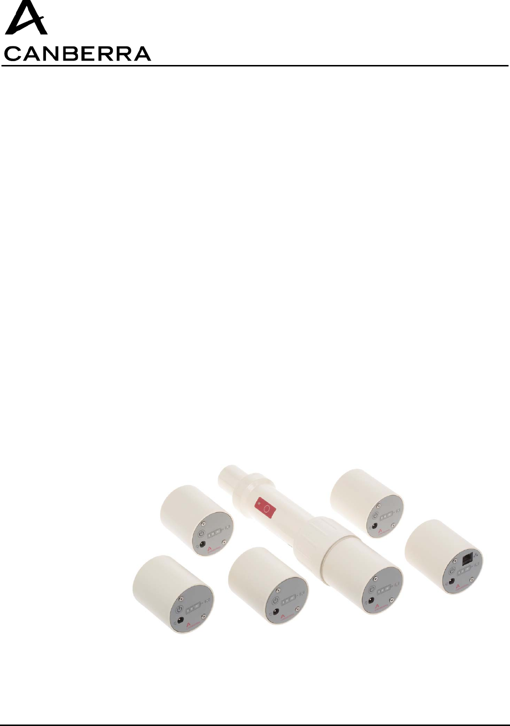
Due to the innovative design of the CSP Probes, Canberra can now offer the CSP-COM.
CSP-COM modules are communication interfaces compatibles with all the CSP probes. They can be
connected to the rear side of the probes by a locking system without any tools.
They are powered by rechargeable battery and a power level indicator is included. They can be used
while connected to the mains (using the provided charger) or working on battery. The working time
depends on the communication system used.
CSP-COM allows every CSP probe to communicate with a monitor equipped with a compatible receiver
(Survey meter, PC etc. …). The modules can be integrated into any system owned by customer thanks
to the tools provided by Canberra (CSP DLL code 82800, CSPS code 78468).
One of the big advantage is for some of them to be able to work wireless.
These modules are available in several versions :
– Wireless :
Bluetooth (82481)
Wifi (83437)
RF 915MHz (83441) + Supervisor / repeater RF 915 MHz (86289)
– Wired :
Ethernet (83442)
RS485 (83438)

USER MANUAL
CSP-COM
CANBERRA Industries
800 Research Parkway
MERIDEN, CT 06450
8 / 26
86338_A
2. DECLARATION OF CONFORMITY (US-FCC)
Concerns CSP-COM Wireless Bluetooth, Wifi, RF915MHz and Wired Ethernet and RS485, and
Supervisor/Repeater 915MHz.
These devices comply with Part 15 of the FCC Rules. Operation is subject to the following two
conditions: (1) these devices may not cause harmful interference, and (2) these devices must accept
any interference received, including interference that may cause undesired operation.
These equipments have been tested and found to comply with the limits for a Class B digital device,
pursuant to part 15 of the FCC Rules. These limits are designed to provide reasonable protection
against harmful interference in a residential installation. These equipments generate use and can
radiate radio frequency energy and, if not installed and used in accordance with the instructions, may
cause harmful interference to radio communications. However, there is no guarantee that interference
will not occur in a particular installation. If these equipments do cause harmful interference to radio or
television reception, which can be determined by turning the equipment off and on, the user is
encouraged to try to correct the interference's by one or more of the following measures:
Reorient or relocate the receiving antenna.
Increase the separation between the equipment and the receiver.
Connect the equipment into an outlet on a circuit different from that to which the receiver is connected.
Consult the dealer or an experienced radio/TV technician for help.
The user may find the following booklet, prepared by the Federal Communications Commission, helpful:
How to identify and Resolve Radio/TV Interference Problems. This booklet is available from the U.S.
Government Printing Office, Washington, D.C. 20402, Stock No. 004-000-00345-4.
Pursuant to Part 15.21 of the FCC Rules, any changes or modifications to these equipments not
expressly approved by CANBERRA may cause, harmful interference and void the FCC authorization to
operate these equipments.
Concerning Wireless devices, operator may keep the equipment at more than 20 cm from the body.
Supervisor/Repeater 915MHz can be used with a Class B Personal Computer and is also certified
under DoC “Declaration of Conformity” procedure.

USER MANUAL
CSP-COM
86338_A
9 / 26 CANBERRA Industries
800 Research Parkway
MERIDEN, CT 06450
3. CHARACTERISTICS
3.1.1. Mechanical characteristics
Length L 100mm (3.94 in)
Width W 55mm (2.16 in)
Weight 200g (0.44 lb)
3.1.2. Electrical characteristics
CSP-COM power supply: voltage range => 4.5 < Vext< 5.5 VDC. Current Max 1800 mA
Cylindrical connector Jack type
Probe power supply : voltage output => 4.75< Vsonde< 5.25VDC.
Current output 20 mA <Isonde<100 mA
Female cylindrical connector code : D104 A066-130
Battery : Li-ion Technology
Charging time : 2 h
Life time : 300 cycles minimum
Caution : Explosion can occur if the battery is replaced by a battery of an incorrect type. Discard
the used batteries according to the instructions.
In case of a long period of storage, the battery needs to be recharged after 6 months.
Ingress protection : IP 40.
Use only the power supply delivered with the CSP-COM :
– Manufacturer : MASCOT ;
– Model : SPU15A-102 ( Mascot )
– Input : 100-240 V , 0.4 A, 47-63 Hz
– Output : 5 V, 2 A
Overvoltage class I device.
This device is also designed for working with an IT type power supply presenting a 230 V voltage
between the phases.
USER MANUAL
CSP-COM
CANBERRA Industries
800 Research Parkway
MERIDEN, CT 06450
10 / 26
86338_A
3.2. ENVIRONMENTAL CHARACTERISTICS
Operating temperature: from -10°C (14°F) to + 50°C (122°F) without power supply; from 0°C (32°F)to
+40°C (104°F) with power supply
Storage temperature : from -25°C to + 60°C (-13°F to 140°F)
Relative humidity: 0 % à 95 % at 35°C (95°F) without condensation.
Maximum altitude of transportation : 12000 m (13123 yd).
Easily decontaminated case but not water tight, as a consequence cases must not get wet when being
cleaned or decontaminated.
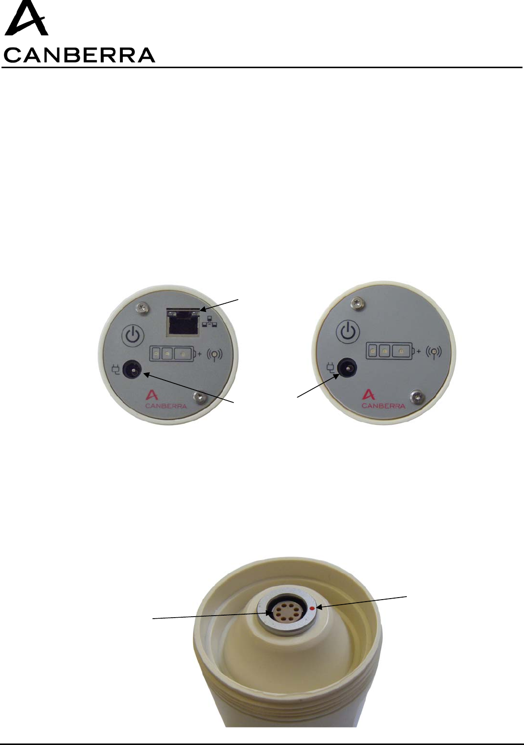
3.3. CONNEXIONS
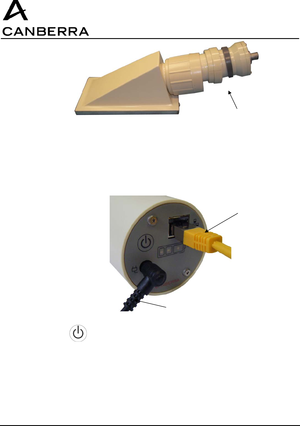
3.3.1. Front side panels
There are 2 kinds of front side panel according to the communication mode.
3.3.2. Rear side
Rear side is the same for all the CSP-COM and presents only one 8-point connector to connect the
probe.
Ethernet and RS485 Wifi, Bluetooth, RF
RJ 45
Power supply
Connector
alignment mark
Connector
D104 A066-130

USER MANUAL
CSP-COM
86338_A
11 / 26 CANBERRA Industries
800 Research Parkway
MERIDEN, CT 06450
3.4. CHARACTERISTICS DEPENDING ON COMMUNICATION MODE
Communication interface Technical characteristics
Ethernet RJ45 Connector
Power supply of CSP-COM:
− External power supply 5 V DC
− Battery for power cuts. (battery life ≥1h
communicating at 9600 bauds)
Maximum communication rate:115200 bauds
Communication range: 100m
Max. nodes on the network = max. capacity of the used Ethernet Hub
Use of shielded twisted pair Cat. 5 cable
RS485 RJ45 Connector
Power supply of CSP-COM:
− External power supply 5 V DC
− Battery for power cuts. (battery life ≥1h
communicating at 9600 bauds)
Maximum communication rate:115200 bauds.
Communication range: 100 m at 115200 bauds, 600m at 9600 bauds
Up to 200 nodes on the network.
Use of shielded cable
Blue Tooth Class II (2.5 mW)
Power supply of CSP-COM:
− External power supply 5 V DC
− Battery (battery life 24h at 9600 bauds)
Maximum communication rate:115200 bauds.
Communication range 15 to 20 m
Up to 7 nodes on the network
N° FCC ID: VPM-CSP-BT

USER MANUAL
CSP-COM
CANBERRA Industries
800 Research Parkway
MERIDEN, CT 06450
12 / 26
86338_A
Wifi Compliant with standard 802.11g (FCC ID: VPM-CSP-WF)
Power supply of CSP-COM:
− External power supply 5 V DC
− Battery for power cuts. (battery life ≥ 1 h at 9600
Bauds)
Maximum communication rate: 115200 bauds
Communication range > 20 m
Max. nodes on the network = max. capacity of the used Wifi interface
Radiofrequency 915 MHz Band - 500 mW (N° FCC : VPM-CSP915)
Power supply of CSP-COM:
− External power supply 5 V DC
− Battery for power cuts (Battery life ≥ 1h
communicating at 4800 bauds with probe)
Maximum communication rate: 4800 bauds
Communication range
− 1 km in free-field
− 300 m inside a building
USER MANUAL
CSP-COM
86338_A
13 / 26 CANBERRA Industries
800 Research Parkway
MERIDEN, CT 06450
4. USE OF THE MODULE
4.1. COMMUNICATION MODE
Whether for the CSP-COM using wireless communication mode (Blue tooth & Wifi) or whether for the
ones using cable mode (Ethernet & RS485), the necessary interfaces (e.g.: Wifi or Ethernet network)
need to be provided by the user to ensure an efficient communication.
4.2. CSP-COM/RF915 PARTICULAR CASE
The CSP-COM/RF915 needs the use of a complementary device added to the PC equipped with
the acquisition software.
This device is a Supervisor/Repeater module. The Supervisor/Repeater (code 86289) modules relay
information between the host computer and the CSP-COM devices deployed in the field. To extend the
communication range of the system, additional Repeater modules may be inserted between the
computer and Supervisor module.
Refer to Chapter 5 for instructions about its installation and use.
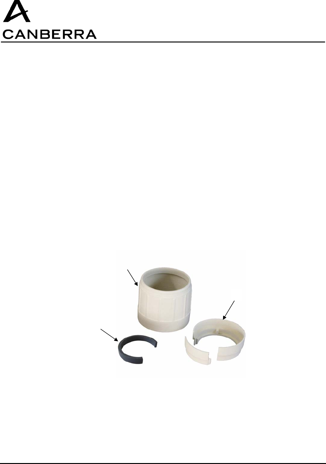
4.3. ASSEMBLY OF THE CSP-COM WITH THE PROBE
A fastening kit compatible with all the CSP probes is delivered with the CSP-COM.
It is made of:
− 1 nut (1)
− 1 two-pieces ring (2) and one adaptor ring (3).
There are two kinds of probe, one with locking connector and the other with non-locking connector
This kit allows to connect these two kinds of probe.
1
2
3
USER MANUAL
CSP-COM
CANBERRA Industries
800 Research Parkway
MERIDEN, CT 06450
14 / 26
86338_A
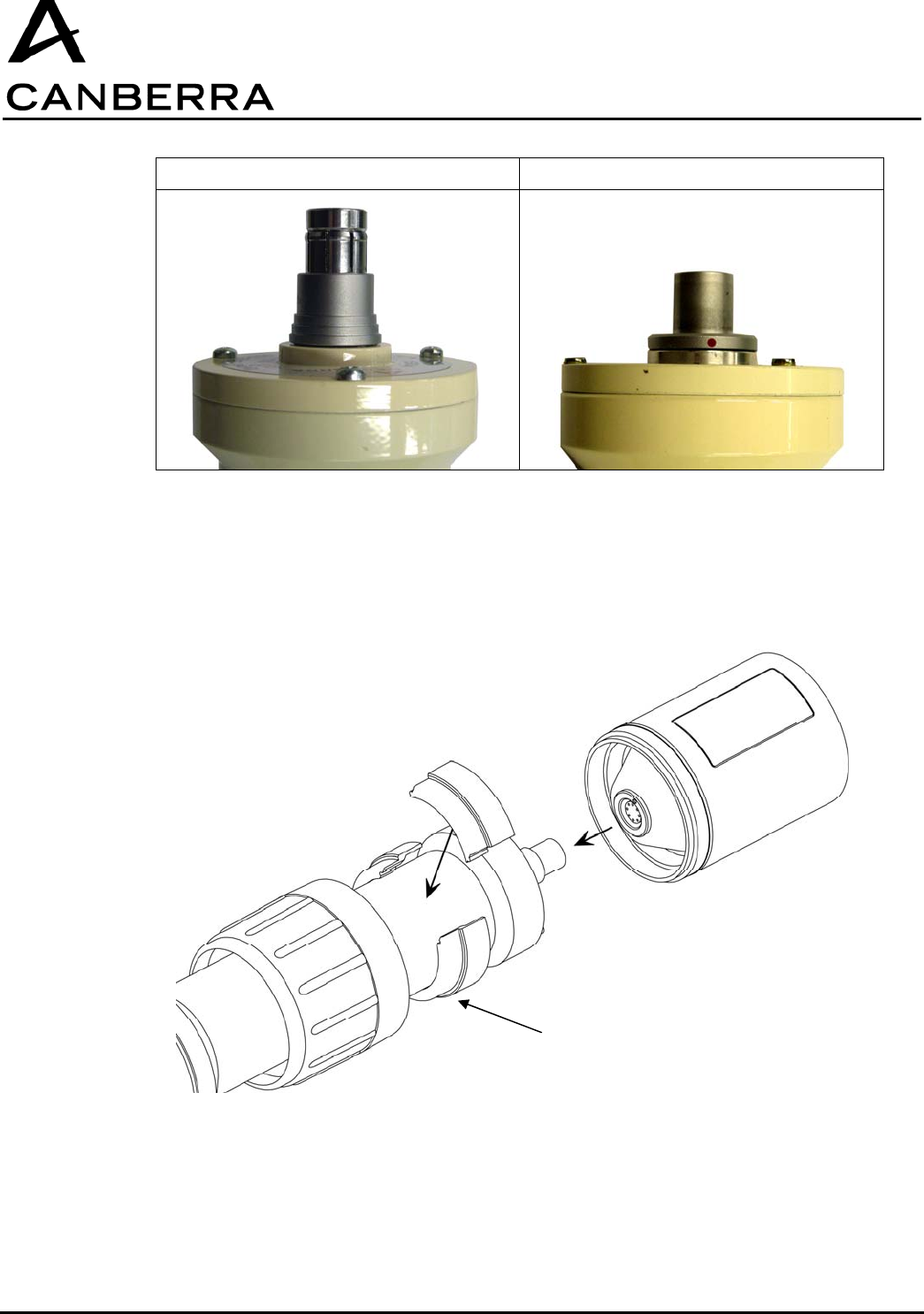
Locking connector Non-locking connector
To assemble the probe with the CSP-Com:
• Place the nut on the handle of the probe.
• For the locking probes : assemble the two parts ring on the handle of the probe.
• For the non locking probes : assemble the two parts ring then place the adaptor ring.
Two parts ring
USER MANUAL
CSP-COM
86338_A
15 / 26 CANBERRA Industries
800 Research Parkway
MERIDEN, CT 06450
• Connect the probe to the module and be carefull while connecting them, that connection's points
situated on each connectors ( module and probe) are faced.
• Screw the nut on the module.
4.4. PUTTING INTO SERVICE
Before the first use, plug the CSP_COM module to its power supply for 2 hours.
For the Ethernet and RS 485 CSP-COM:
• Plug the cable connecting the monitor to the CSP-COM.
For all types of CSP-Com :
• Press to power on the module.
Network cable
RJ 45
Power supply + 5V 2 A
Adaptor ring
USER MANUAL
CSP-COM
CANBERRA Industries
800 Research Parkway
MERIDEN, CT 06450
16 / 26
86338_A
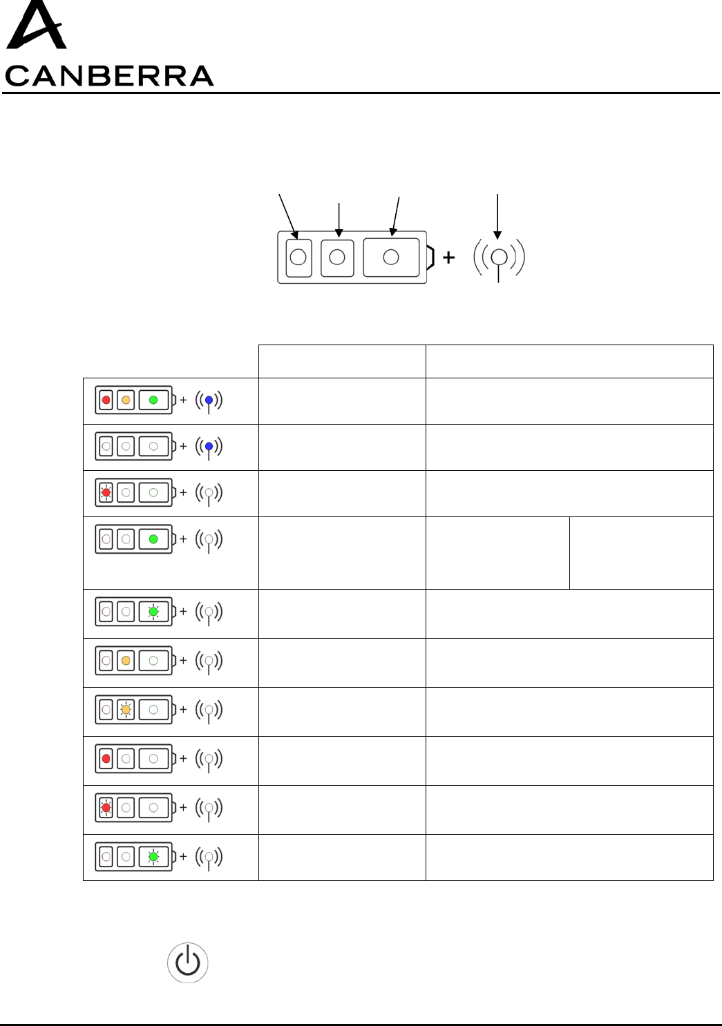
4.5. MEANING OF THE LED LIGHTING DURING FUNCTIONING
Comments Events
4 fixed lit LEDs Starting of CSP-COM
Brief lighting of the blue
LED
Active communication
Very fast flashing of the
red LED
First charge
Fixed lit green LED Battery connected to
the power grid,
Battery charge ≥
100%
Missing battery,
power supply
connected to the
power grid
Slow flashing green LED Working on battery,
100 % > battery charge> 33 %
Fixed lit orange LED Battery connected to the power grid,
100 % > battery charge > 10 %
Slow flashing orange
LED
Working on battery
33 % ≥ batterie charge > 10 %
Fixed lit red LED Battery connected to the power grid
Battery charge ≤ 10%
Slow flashing red LED Working on battery
Battery charge ≤ 10%
Fast flashing green LED Boot mode
4.6. SWITCHING-OFF THE DEVICE
• Press until all the LEDs simultaneously light then release.
orange red green blue
battery communication
USER MANUAL
CSP-COM
86338_A
17 / 26 CANBERRA Industries
800 Research Parkway
MERIDEN, CT 06450
4.7. FIRMWARE UPDATE
It is possible to update the firmware of CSP_COM by downloading it from a PC equipped with CSPS
software.
CSPS (Canberra Smart Probe software): code 78468
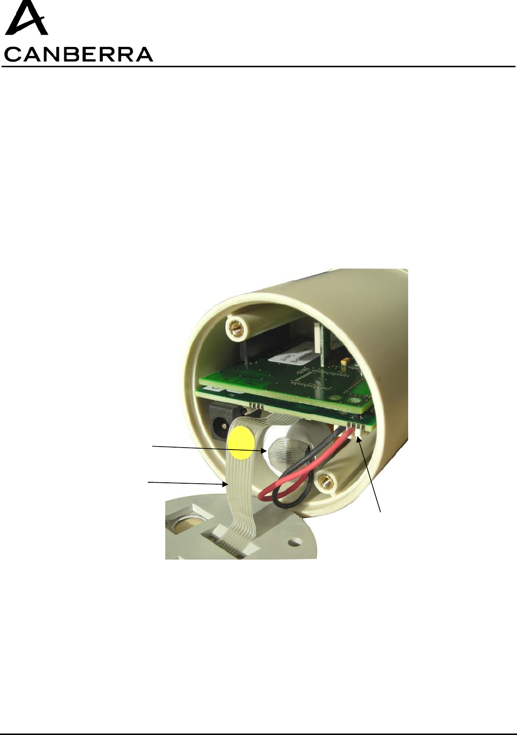
4.8. REPLACING THE BATTERY
The internal battery has a life time of around 300 cycles.
Beyond that, it’s performances may be significantly reduced. Therefore, It is recommended to replace
the battery every 300 cycles.
For replacing the battery:
• Remove the 2 screws fixing the front panel,
• Move carefully the front panel apart from the case because of the LEDs connections,
• Unplug the battery,
• Remove the battery,
• Put the new battery in its socket,
• Plug the battery,
• Put back the front panel,
• Screw the screws.
LEDs
connections
battery
Battery
Connection
USER MANUAL
CSP-COM
CANBERRA Industries
800 Research Parkway
MERIDEN, CT 06450
18 / 26
86338_A
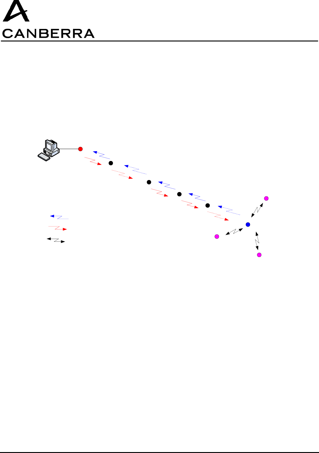
5. SUPERVISOR / REPEATER RF 915MHZ
A standard CSP-COM RF system includes a set of CSP-COM, up to 200 devices maximum per system,
and one or more Supervisor/Repeater modules. The Supervisor/Repeater modules relay information
between the host computer and the CSP-COM devices deployed in the field. To extend the
communication range of the system, additional Repeater modules may be inserted between the
computer and Supervisor module.
PC
Supervisor
Repeater
Level 1
CSP-COM
Repeater
Level N-1
Repeater-PC
Repeater
Level N Repeater
Level N+1
Supervisor to PC RF communications
PC to Supervisor RF communications
Supervisor – CSP-COM RF communications
CSP-COM
CSP-COM
USER MANUAL
CSP-COM
86338_A
19 / 26 CANBERRA Industries
800 Research Parkway
MERIDEN, CT 06450
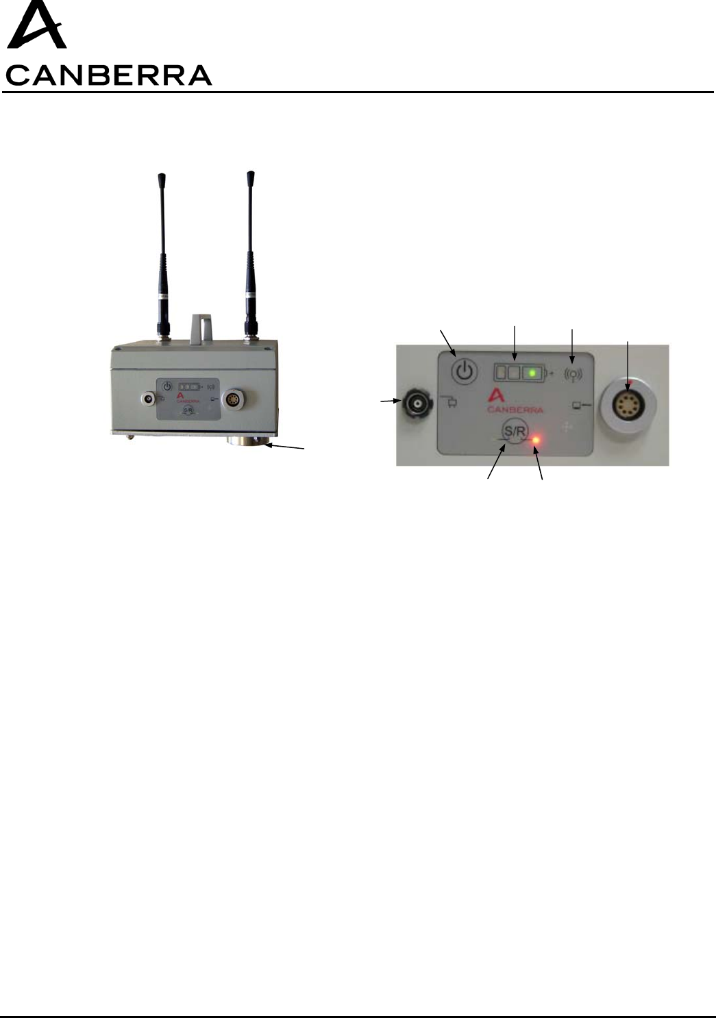
5.1. DESCRIPTION
1. Magnetic Feet:
The three feet on the base of the module allow it to be magnetically mounted to most common steel or
other ferromagnetic structures.
2. External Power Connector:
This connector accepts external power from the supplied 5V-5A AC/DC adapter to charge the internal
battery.
3. Power Button:
Pressing and holding the power button momentarily will switch the Supervisor/Repeater module on or
off alternately.
4. Green, Orange, and Red ”Battery” Status LEDs:
When the Supervisor/Repeater is in operation and is not connected to its external power adapter, the
appropriate colored LED will blink to indicate the remaining capacity of the internal battery. When the
GPSCOM is connected to its external power adapter, the appropriate colored LED will turn on steady to
indicate the battery charging status.
1
3 4 5 6
8
2
7

USER MANUAL
CSP-COM
CANBERRA Industries
800 Research Parkway
MERIDEN, CT 06450
20 / 26
86338_A
5. Blue “Link” Status LED:
The Blue status LED indicates when the Supervisor/Repeater module has been successfully connected
to the CSP-COM network, either by direct connection to the host computer or through RF link to another
S/R module.
6. Data connector:
The data connector is a serial interface, which communicates with the host computer through the
supplied Serial-to-USB data cable.
7. Red “S/R” Status LEDs:
A corresponding Red status LED adjacent to the “S/R” button will turn on to indicate the module
operating mode as either a Supervisor or a Repeater.
8. “S/R” Button:
Pressing and holding the power button momentarily will switch the Supervisor/Repeater module
operating mode between Supervisor or Repeater.
5.2. SPECIFICATIONS
Environmental:
Operating Temperature Range -20oC to +60oC (on battery)
-20
oC to +50oC (battery charging)
Storage Temperature Range -40oC to +80oC
Humidity 0 to 95% at +35oC
Altitude 12000m (in transport only)
Specification IP66
Input Voltage:
Operating Range +4.5 to +5.5VDC
Maximum current 5A
Protection Polarity inversion
Overvoltage (up to 24VDC)
Connector Fischer DEU 104 A066
Use only the power supply provided with the SUPERVISOR/REPEATER MODULE:
Manufacturer: CINCON ELECTRONICS CO., LTD
Model: TR30RA050
Input: 100-240 V, 47-63 Hz, 0.8 A
Output: 5 Vdc, 5 A
Caution: The plug of the direct plug-in power supply is used as the disconnect device, it shall remain
accessible after installation.

USER MANUAL
CSP-COM
86338_A
21 / 26 CANBERRA Industries
800 Research Parkway
MERIDEN, CT 06450
Internal Battery:
Type Lithium-Ion
Operating time 70 hours minimum
Charging time 13 to 17 hours
Lifetime 300 cycles
CAUTION: Risk of explosion if battery is incorrectly replaced. Replace only with the same or
equivalent type recommended by the manufacturer. Dispose of used batteries according to the
manufacturer's instructions
Communication:
Frequency 915 MHz (US)
Range 1000 m (unobstructed)
300 m (inside building)
Dimensions
Length 160 mm
Width 160 mm
Height 80 mm
Material Aluminium alloy
Color beige
Cleaning Resistance Alcohol (90% solution)
Certifications & Approvals:
CEM/Radio 915MHz FCC 15-247 (US) FCC ID: VPM-RS-915
5.3. NORMAL POWER ON/OFF SEQUENCE
The following procedure outlines the normal operating sequence of the Supervisor/Repeater module.
• For a Supervisor-PC or Repeater-PC, connect the Supervisor/Repeater module to the host
computer USB port using the supplied data communication cable. Note that a Secondary-
Repeater or Supervisor is operated as a standalone module, and would not be connected to a
PC.
• Switch on the Supervisor/Repeater module by pressing and briefly holding the power button until
all four status LEDs turn on.
• If external power is connected to the module, the Blue status LED will turn on briefly and the
Supervisor/Repeater module will indicate its charging status by turning on the appropriate color
LED as follows:
Green = 100% capacity (charge complete)
Orange = less than 99% capacity
Red = less than 10% capacity
USER MANUAL
CSP-COM
CANBERRA Industries
800 Research Parkway
MERIDEN, CT 06450
22 / 26
86338_A
If no external power is connected, all “Battery” and “Link” status LEDs will turn on briefly, followed by
the battery level indicated by a blinking status LED as follows:
Green: greater than 33% capacity
Orange: less than 33% capacity
Red: less than 10% capacity
• The Supervisor/Repeater module will now also indicate its operating mode before it was last
switched off, by turning on the corresponding Red “S” or “R” status LED next to the “S/R” button.
• To change the mode between Supervisor or Repeater operation, press and momentarily hold the
“S/R” button. All “Battery” and “Link” status LEDs will turn on briefly, then the status LEDs will
indicate the battery level or charging status along with the new operating mode. (Note that when
external power is connected, changing the S/R mode will also reset the module back to Charge
mode and it will be necessary to switch power on again. When switched back on, the S/R module
will be in the newly selected operating mode.)
• The Blue status LED will only turn on after a “Start Network” command has been issued by the
host computer and the S/R module has been successfully linked to the network, either by direct
connection to the host computer or through RF link to another S/R module.
• To switch off the S/R module, press and briefly hold the power button again until all four “Battery”
and “Link” status LEDs turn on. After releasing the button, all status LEDS will be off and the S/R
will be powered off.
• If the external power adapter is connected, the S/R module will automatically enter Charge mode
and the charging status will be indicated by a Red, Orange, or Green status LED according to the
battery capacity as described above.
5.4. DYNAMIC SUPERVISOR/REPEATER MODULE CONNECTIONS
The network allows for removal and insertion of Repeater modules if necessary to extend the
communication range of the system. The sections below describe the response of the system and the
required user interaction for different configurations and events.
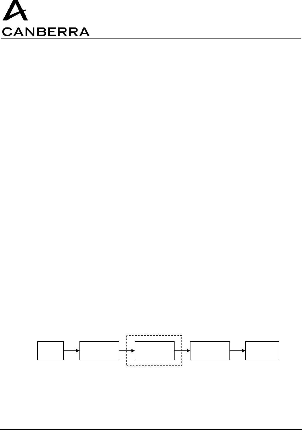
5.4.1. Installing or Removing Repeater Modules
In a system utilizing at least one Repeater module (Repeater-PC) and a Supervisor module, the
communication link established between CSP-COM devices and the Supervisor module is not affected
by adding or removing the Repeater-PC or Secondary-Repeater modules. All communication data for
the system is stored in the Supervisor, which will remain linked with the CSP-COM devices. Data flow
from the CSP-COM devices to the host computer will be momentarily interrupted if a Repeater module
is removed, but system operation will restore itself automatically once the communication chain has
been re-established.
PC Repeater-PC Secondary-
Repeater(s) Supervisor CSP-COM
Optional
USER MANUAL
CSP-COM
86338_A
23 / 26 CANBERRA Industries
800 Research Parkway
MERIDEN, CT 06450
5.4.1.1. Removal of a Repeater-PC or Secondary-Repeater Module
• Follow the steps in section 5.3 above to switch off and remove either a Secondary-Repeater or
Repeater-PC module.
• All Repeater modules between the computer and the Repeater that has been removed will
remain in the network, and their Blue “Link” status LEDs will stay on. All Repeater modules after
this point, along with the Supervisor, will become disconnected and their “Link” status LEDs will
turn off.
5.4.1.2. Insertion of a Repeater-PC or Secondary-Repeater Module
• Follow the steps in section 5.3 above to install a new Secondary-Repeater module.
• The Blue “Link” status LED of the newly installed Secondary-Repeater module will turn on to
indicate when it has been successfully synchronized and linked to the network.
• If any downstream Repeaters and the Supervisor had been previously disconnected, their Blue
“Link” status LEDs will turn back on once the have automatically reconnected to the network.
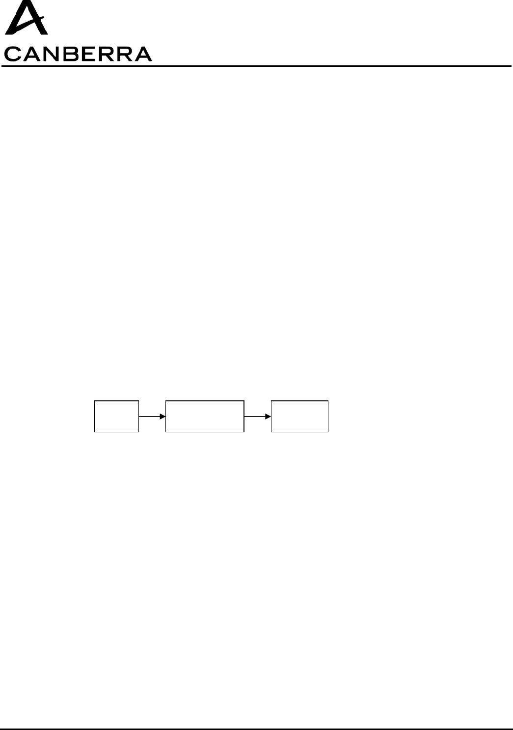
5.4.2. Installing or Removing Supervisor Modules
In a system containing only a Supervisor-PC module, it is not possible to insert additional Repeater
modules once the system is in operation without restarting and reconfiguring the system to some
extent. In this case, proper functionality of the system requires the system operating data and CSP-
COM communication table stored in the Supervisor to be reset. This occurs whenever the serial data
cable is disconnected from the Supervisor-PC, and the role of the module changes from Supervisor-PC
to standalone Supervisor.
5.4.2.1. Removal of a Supervisor-PC or Supervisor Module
• Follow the steps in section 5.3 above to switch off and remove either a Supervisor-PC or
Supervisor module.
• Any Repeater modules in the system will remain connected in the network, and their Blue “Link”
status LEDs will stay on. The Supervisor however will become disconnected from the network
once it has been switched off, and all system data in the Supervisor will be lost.
PC Supervisor-PC CSP-COM

USER MANUAL
CSP-COM
CANBERRA Industries
800 Research Parkway
MERIDEN, CT 06450
24 / 26
86338_A
5.4.2.2. Insertion of a Supervisor-PC or Supervisor Module
• Follow the steps in section 5.3 above to install a new Supervisor module.
• To restart the CSP-COM network, there are three possible procedures:
a) Shutdown and restart all the CSP-COM devices. Place the Supervisor module into network
scan/search mode, then scan and connect all CSP-COM devices, as described above. This
solution is the most straightforward, but may require a significant length of time if the system
contains a large number of CSP-COM devices.
b) If all of the identifiers of the CSP-COM devices previously connected are known are still
stored in the PC , the following procedure may be used: Place the Supervisor module into
standby mode. Send a “connect” frame from the PC to each CSP-COM previously connected.
This solution is quick, but requires that the PC has stored the identifiers of the connected
CSP-COM devices.
c) Change the network number ID of the new Supervisor and all of the Repeaters in the system.
This solution requires the reconfiguration of all the Repeaters and Supervisor, and imposes
the retrieval of all of the deployed modules. It is therefore only practical in a network which
contains only one or two Repeaters maximum.
5.5. ENABLING THE PROGRAM MODE
The following procedure outlines the steps necessary to change the internal firmware of the
Supervisor/Repeater module.
• Connect the S/R module to the host computer USB port using the supplied data communication
cable.
• Switch on the S/R by pressing and briefly holding the power button until all four “Battery” and
“Link” status LEDs turn on.
• Press and hold the power button again until the Green status LED blinks rapidly, and the Red “S”
or “R” status LED turns off. This indicates that the S/R is now ready to receive a firmware change
through the computer connected to the serial data connector.
• When programming is completed, press and briefly hold the power button again until all four
“Battery” and “Link” status LEDs turn on. The S/R module will now return to its normal operating
mode, and the status LEDs will indicate the battery level or charging status along with the present
operating mode.
• To switch off the S/R module, press and briefly hold the power button again until all four “Battery”
and “Link” status LEDs turn on. After releasing the button, all status LEDS will be off and the S/R
module will be powered off.
5.6. CHARGING THE BATTERY
The following procedure outlines the steps to charge the S/R internal battery. Note that it is possible to
interrupt the charging process at any time by disconnecting the external power adapter, and no damage
to the internal battery will result.
• Connect the supplied AC/DC power adapter to the S/R, and connect the adapter to a 100-240V
50/60Hz outlet using the appropriate plug.
• The S/R will automatically begin charging its internal battery, and will indicate the charge status
with the appropriate color LED as follows:
Green = 100% capacity (charge complete)
Orange = less than 99% capacity
Red = less than 10% capacity

USER MANUAL
CSP-COM
86338_A
25 / 26 CANBERRA Industries
800 Research Parkway
MERIDEN, CT 06450
• When charging is complete, the Green LED will turn on and the external power adapter may be
disconnected.
5.7. NOTES ON COMMUNICATION OPERATIONS
Supervisor must not be turned off once communicating with CSP-COM, otherwise entire network must
be restarted.
Blue status LED must remain on at all times – if LED turns off, indicates communication fault.
If software is closed, Supervisor will continue to communicate with CSP-COM – it is not required to re-
scan and re-start network.
Connection or disconnection of data cable will force reset of S/R microcontroller.
5.8. REPLACEMENT COMPONENTS
The following components are available for direct replacement through the Canberra Service
department:
− AC/DC Power Adapter (5V@5A): TR30RA050 from CINCON ELECTRONICS CO., LTD
− RF Antenna: code 85969
Antenna must not be removed nor replaced by another one

USER MANUAL
CSP-COM
CANBERRA Industries
800 Research Parkway
MERIDEN, CT 06450
26 / 26
86338_A