CANBERRA RMSA7070822 Digital Security Device User Manual Blue Sky Airlines
Canberra Industries Digital Security Device Blue Sky Airlines
CANBERRA >
User Manual

Remotely Monitored Seal Array (RMSA)
User’s Manual
SFG-MAN-001
Revision: 1.7
107 Union Valley Road
Oak Ridge, TN 37830
Phone: (865)220-
6300
Fax: (865)483-0406
2016 CANBERRA
Table of Contents
PREFACE ....................................................................................................................................................... 1
INTRODUCTION ........................................................................................................................................... 1
1.1 RMSA SYSTEM OVERVIEW ........................................................................................................................... 1
1.2 THEORY OF OPERATION ................................................................................................................................. 3
1.3 SEAL ................................................................................................................................................................ 5
1.4 TRANSLATOR .................................................................................................................................................. 9
1.5 RMSA REVIEW GUI .................................................................................................................................... 13
RMSA SET-UP ............................................................................................................................................ 15
2.1 RMSA SEAL PROGRAMMING AND CONFIGURING....................................................................................... 15
2.2 RMSA TRANSLATOR SET-UP AND LINUX BOOTSTRAP .............................................................................. 27
2.3 WINDOWS XP REMOTE REVIEW APPLICATION HOST ........................ ERROR! BOOKMARK NOT DEFINED.
RMSA KEY GENERATION ....................................................................................................................... 35
3.1 RMSA KEY GENERATION............................................................................................................................ 35
RMSA SECURITY ...................................................................................................................................... 37
4.1 COLLECT / STORE SEAL MESSAGES WITH NO CONSOLE ACCESS ............................................................... 37
4.2 AUTHENTICATION AND ENCRYPTION OF MESSAGES................................................................................... 37
4.3 FIBER LENGTHS ............................................................................................................................................ 38
REMOTE REVIEW OF SEAL DATA ......................................................................................................... 40
5.1 RMSA REVIEW GUI INSTALLATION AND CONFIGURATION ....................................................................... 40
5.2 LOADING COLLECTED RMSA DATA ........................................................................................................... 41
5.3 SORTING AND ANALYZING RMSA DATA .................................................................................................... 45
5.4 REQUESTING RMSA SEAL DATA ................................................................................................................ 53
Table of Figures
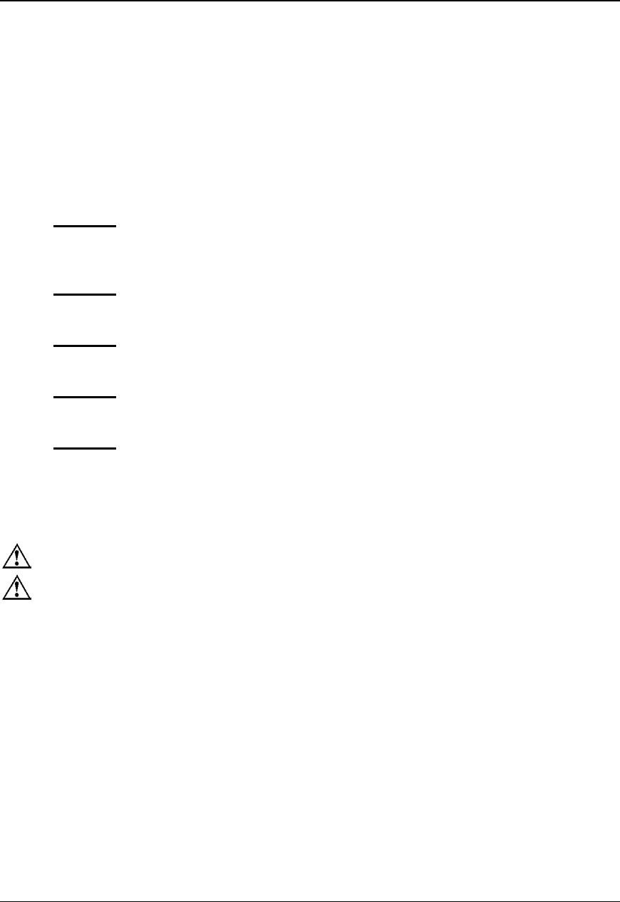
Figure 1 Capability and Implementation Relational Diagram ....... 2
Figure 2 RMSA System Configuration .......................................... 4
Figure 3 Seal in Case .................................................................... 5
Figure 4 Block Diagram of the Seal .............................................. 7
Figure 5 Translator Block Diagram ............................................. 10
Figure 6 Type Length Value (TLV) Format ................................. 12
Figure 7 Example RMSA System Installation ............................. 14
Figure 8 Battery Holders (Seal Not in Case) .............................. 16
Figure 9 Out of Case Seal and Programmer Set -up ................. 17
Figure 10 Seal Programmer Inside Case ................................... 17
Figure 11 Installing Plastic Optical Fiber (POF)………………..38
Preface
Inside This Manual
This document describes all of the procedures necessary to operate the Remotely Monitored
Seal Array system including the Seals, their supporting Translators, and communications
subsystems. The User is expected to be familiar with the basic PC and MS/DOS procedures.
This document is divided into the following five chapters:
Chapter 1 RMSA System Description - This section includes an RMSA system overview
and theory of operation and describes the Seal, Translator and Remote Review
Application software.
Chapter 2 RMSA System Set-Up - This section provides step-by-step instructions for
setting up each of the RMSA System components.
Chapter 3 RMSA Key Generation - This section contains the procedures for generating
cryptographic keys that will be loaded into the Seal.
Chapter 4 RMSA Security - This section discusses RMSA Security via encryption,
authentication, and default keys for a specific Seal.
Chapter 5 Remote Review of Seal Data - This section demonstrates the Remote Review of
Seal Data.
Safety Guidelines
Caution – Do not operate this unit in a manner not specified in this document.
Caution – Only use this unit with the manufacturer provided input power cable.
FCC Compliance
Compliance Statement (Part 15.19)
The enclosed hardware device complies with Part 15 of the FCC Rules. Operation is subject to the following two
conditions: (1) This device may not cause harmful interference, and (2) This device must accept any interference
received including interference that may cause undesired operation.
Warning (Part 15.21)
Changes or modifications not expressly approved by Canberra Industries could void the user’s authority to operate
the equipment. Manufacturer is not responsible for any radio or TV interference caused by unauthorized
modifications to this equipment.
Compliance Statement (Part 15.105(b))
This equipment has been tested and found to comply with the limits for a Class B digital device, pursuant to Part
15 of the FCC Rules. These limits are designed to provide reasonable protection against harmful interference in a
residential installation. This equipment generates, uses and can radiate radio frequency energy and, if not installed
and used in accordance with the instructions, may cause harmful interference to radio communications. However,
REMOTELY MONITORED SEAL ARRAY(RMSA)
SFG-MAN-001
REVISION: 1.7
2016 CANBERRA
I

there is no guarantee that interference will not occur in a particular installation. If this equipment does cause
harmful interference to radio or television reception, which can be determined by turning the equipment off and on,
the user is encouraged to try to correct the interference by one or more of the following measures:
• Reorient or relocate the receiving antenna
• Increase the separation between the equipment and receiver
• Connect the equipment into an outlet on a circuit different from that to which the receiver is connected
• Consult the dealer or an experienced radio/TV technician for help
Industry Canada (IC) regulatory information
This device complies with Industry Canada license-exempt RSS standard(s). Operation is subject to the following
two conditions: (1) this device may not cause interference, and (2) this device must accept any interference,
including interference that may cause undesired operation of the device.
Le présent appareil est conforme aux CNR d'Industrie
Canada applicables aux appareils radio exempts de licence. L'exploitation est autorisée aux deux conditions
suivantes : (1) l'appareil ne doit pas produire de brouillage, et (2) l'utilisateur de l'appareil doit accepter tout
brouillage radioélectrique subi, même si le brouillage est susceptible d'en compromettre le fonctionnement.
Class B digital device notice
This Class B digital apparatus complies with Canadian
ICES-003, RSS-Gen and RSS-210.
Cet appareil numérique de la classe B est conforme à
la norme NMB-003, CNR-Gen et CNR-210 du Canada.
• The system antenna(s) used for this transmitter must be installed to provide a separation distance of at least
20cm from all the persons and must not be co-located or operating in conjunction with any other antenna or
transmitter, except in accordance with FCC and Industry Canada multi-transmitter product procedures.
• The system antenna(s) used for this module must not exceed 10dBi (CDMA BC0) and 9.31dBi (CDMA BC1)
for mobile and fixed operating configurations. Users and installers must be provided with antenna installation
instructions and transmitter operating conditions for satisfying RF exposure compliance.
Translator Input Power
Voltage: 100-240 VAC, 50-60Hz
Power Consumption: .75A
Prepared by:
Author(s): Michael Fontanarosa, Tammy Wenderlich
II
REMOTELY MONITORED SEAL ARRAY(RMSA)
SFG-MAN-001
REVISION: 1.7
2016 CANBERRA

Introduction
Welcome to the Remotely Monitored Seal Array (RMSA) system provided by Canberra and
Sandia National Labs. RMSA was designed to meet the needs of a large base of Users who
require more data storage features, better RF performance, longer battery life, enhanced
security and other more powerful functions. Figure 1 provides a pictorial representation of how
the RMSA System fits within the Secure Sensor Platform (SSP) product family constellation in
terms of its complexity and shared capabilities.
The RMSA Seal monitors a fiber optic loop, records tamper events, provides autonomous and
requested State of Health via encrypted and authenticated messages. This information is
stored in the Seal, remotely via the RMSA Translator and reviewed through the Remote
Review Application. The Authenticated Switch version of the Seal includes magnetic sensors
and activating magnets such that a pair of Authenticate Switch Seals can be used to create a
balanced magnetic switch suitable for monitoring doors, containers and other articles where
one surface moves away from another under authorized conditions.
1.1 RMSA System Overview
The RMSA system consists of Seals, a Translator, a Programming Card interface as well as
the Remote Review Application. The RMSA system provides the following features:
• Offers a low cost solution for monitoring Sealed components
• Incorporates high reliability
• It is inexpensive compared to earlier RF Seals
• Ensures surveillance capabilities available for a long duration
• Provides requested or periodic state of health updates
• Monitors and records date and time of any Seal tamper or other events
• Secures Seal data with encryption and authentication techniques
• Allows remote review of Seals
• Can receive messages from multiple Seals while polling for data via Remote Review
• Requires no license for its low power 900 MHz ISM band RF communication
Each of these features will be discussed in this RMSA User Guide.
Chapter
1
REMOTELY MONITORED SEAL ARRAY(RMSA)
SFG-MAN-001
REVISION: 1.7
2016 CANBERRA
1
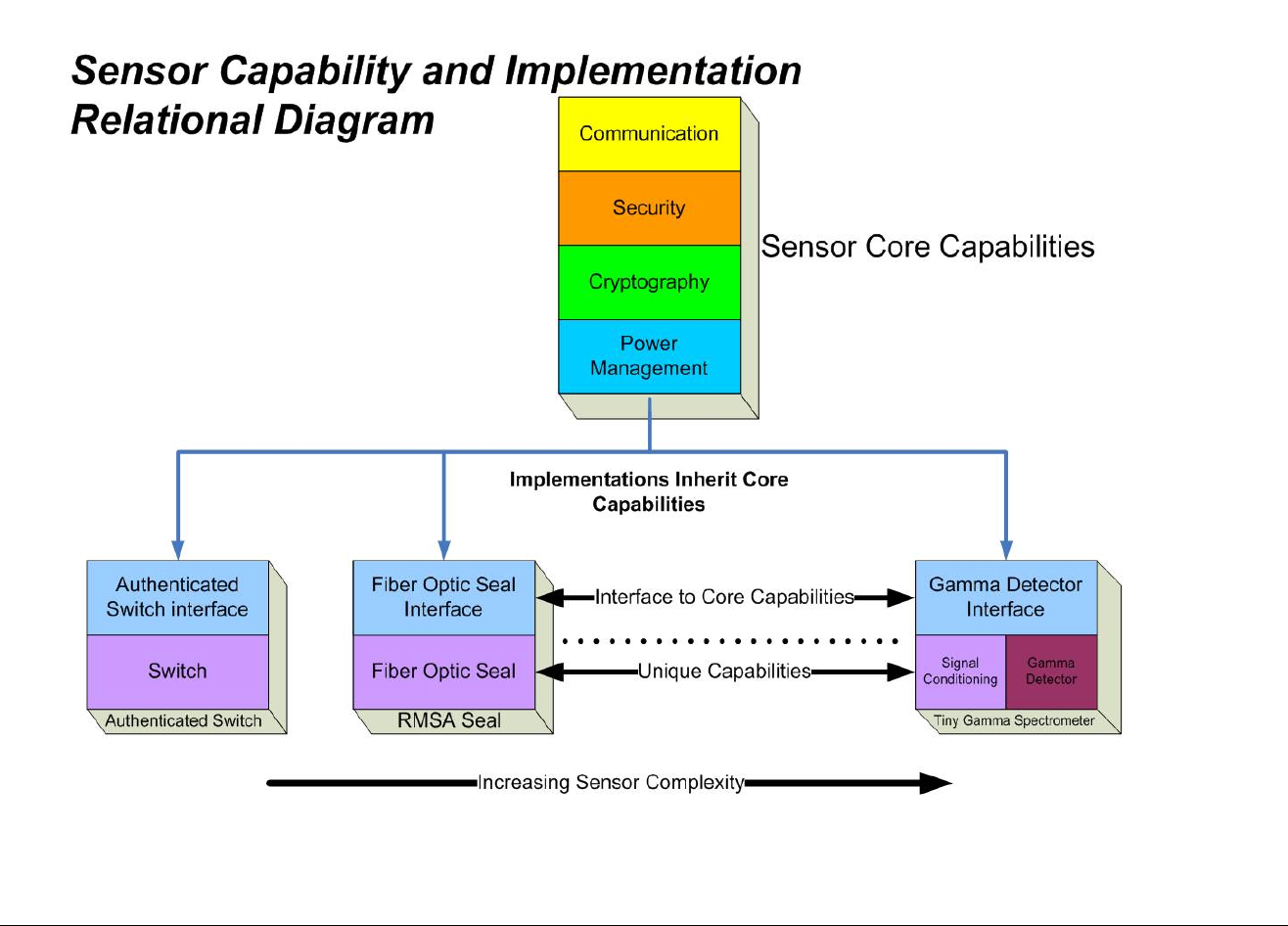
Figure 1 Capability and Implementation Relational Diagram
REMOTELY MONITORED SEAL ARRAY(RMSA)
SFG-MAN-001
REVISION: 1.7
2016 CANBERRA
2

1.2 Theory of Operation
The RMSA allows for monitoring of a fiber optic or authenticated switch sensor as a Seal. See
Figure 2 for an overview of the RMSA system configuration. Seal data is collected with an
RMSA Translator with Translator/Seal communications via a no-license, low power RF
communications channel. Seal data is encrypted, authenticated, and stored before transfer to
the Translator as the Translator is an unsecure device. A Microsoft Windows (XP-based)
Remote Review Application host can decrypt and authenticate the data stored on the
Translator for inspector analysis. A TCP/IP (Ethernet) connection between the Translator and
the Remote Review Application host facilitates the transfer of data from the Translator to the
Remote Review Application. In addition to remote review, this network connection is used to
allow the inspector to interrogate specific Seals for state-of-health or to request re-send of a
specific Seal message.
The RMSA system is capable of supporting three configuration modes of operation. These
three modes are designated standalone mode, local host supported mode and remote
monitoring mode. In the standalone configuration the system hardware may consist of many
active Seals and one Translator, which sits unmonitored for long periods of time. The local
host supported configuration is via an Ethernet interface connected directly to a local host
computer. The remote monitoring mode is similar to the local host mode but is via the internet
to allow monitoring by a host computer of the RMSA system over the internet.
The Programming Card has several functions. It is used to provide power via an external
power supply, a USB interface or from a Microchip compatible programming device. It also
converts the Microchip RJ12 connector 6-wire programming cable to the RMSA 8-wire
interface cable. The RMSA interface cable is used to program the microcontroller code and
Seal personality information that is unique to each Seal. It also provides the interface between
an external USB device, such as a PC, and the UART on the Seal, for personality
programming and debugging.
REMOTELY MONITORED SEAL ARRAY(RMSA)
SFG-MAN-001
REVISION: 1.7
2016 CANBERRA
3
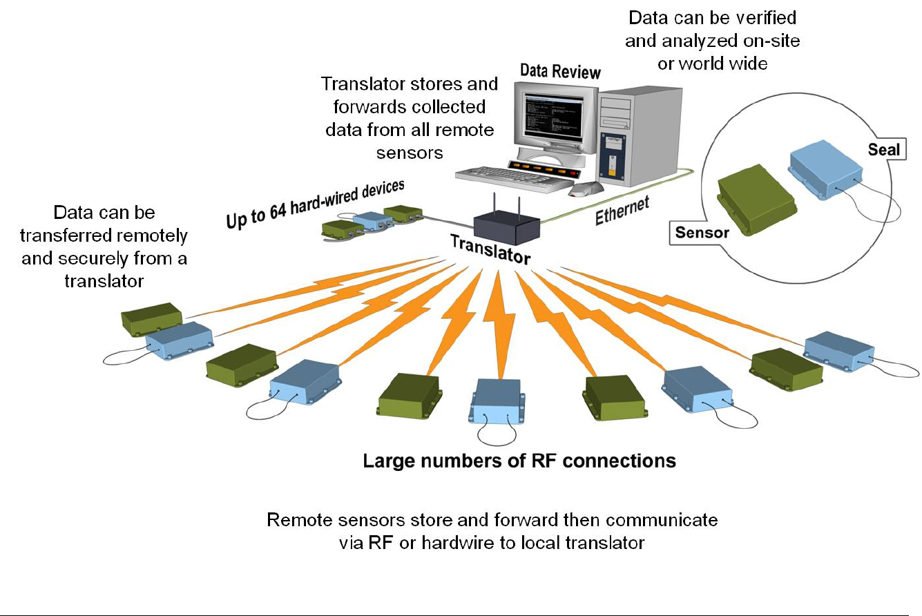
Figure 2 RMSA System Configuration
REMOTELY MONITORED SEAL ARRAY(RMSA)
SFG-MAN-001
REVISION: 1.7
2016 CANBERRA
4
1.3 Seal
The Seal's design is rugged and resistant to tampering. Its electronics are in a tamper
indicating plastic housing. See Figure 3 for a picture of the prototype version of Seal in its
case. A pair of tamper switches is used to detect any opening of the Seal housing. The Seal
housing may be opened to replace the internal batteries. Openings are recorded as tamper
events. The Seal is contained in either a white PVC or a blue and white swirl polycarbonate
plastic overlapping two piece case that contains an O-ring Sealing system for environmental
protection. The Plastic Optical Fiber (POF) cable connectors have special Delrin® plastic
ferules along with O-ring Sealing gaskets.
Figure 3 Seal in Case
Advantages of using the RMSA Seal include the following:
• Can be reused indefinitely
• Can be read in situ without removal from the Sealed item
• No external power required, battery operated
• Provides intrinsic tamper indication
• Easily installed
• One or multiple Seals can be read remotely
The Seal stores data and then forwards this data securely to a local Translator via low
power RF communication. As many as 2000 normal State of Health messages are stored
locally in the Seal in a non-volatile circular memory buffer. This locally stored Seal data
can be retrieved manually by the User by using the Send Message Protocol should RF
transmission be interrupted during normal operation.
REMOTELY MONITORED SEAL ARRAY(RMSA)
SFG-MAN-001
REVISION: 1.7
2016 CANBERRA
5

The Seal is comprised of the following major components: the Fiber Optic Cable, a Fiber Optic
Emitter and a Fiber Optic Receiver, a Microcontroller, Memory, an RF Transceiver and Real
Time Clock. Other inherent components include the Battery Pack, Personality and Security
Key programming, and the Programming Interface. See Figure 4 for a block diagram of the
Seal.
Authenticated Switch Seals contain all of the components in the Seal, and additionally have a
complementary set of magnetic switches, one operating as normally closed and the other
operating as normally open. There is also a strong magnet installed in the housing such that
when two Authenticated Switch modules are installed face to face, the magnet from one
activates the magnetic switches on the other module.
REMOTELY MONITORED SEAL ARRAY(RMSA)
SFG-MAN-001
REVISION: 1.7
2016 CANBERRA
6
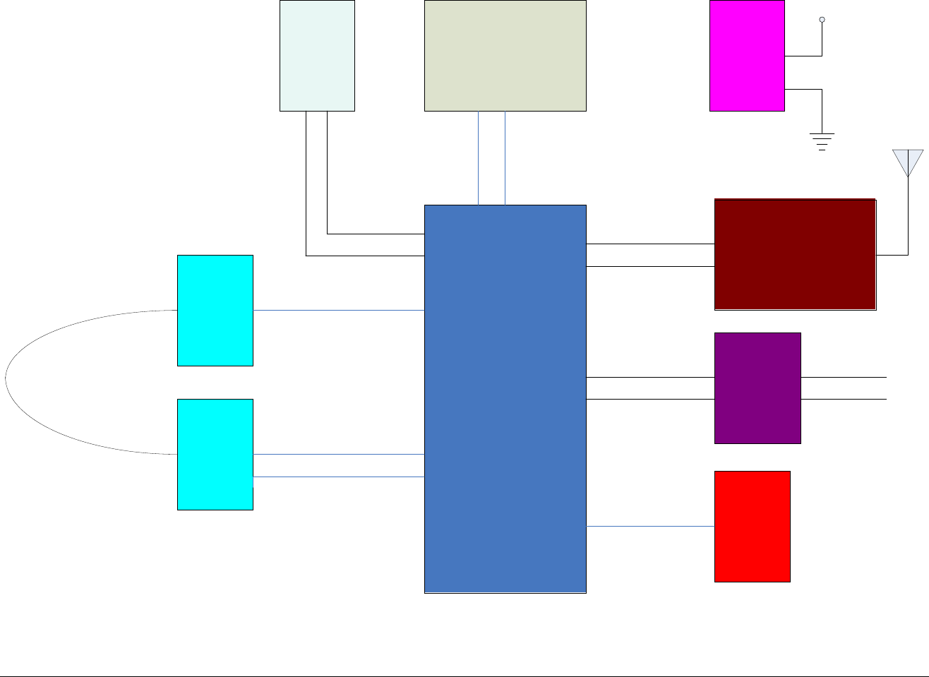
Figure 4 Block Diagram of the Seal
PIC
18
FL
6722
Microcontroller
Real Time Clock
CC
1100
RF Transceiver
Memory
Fiber Optic
Emitter
Fiber Optic
Receiver
Tamper
Battery
Pack
I
2
C
SPI
Programming
Interface
TX
/
RX
To USB
Programming
Cable
VDD
(
unregulated
)
30
Meters
1
mm Plastic Fiber
SPI
REMOTELY MONITORED SEAL ARRAY(RMSA)
SFG-MAN-001
REVISION: 1.7
2016 CANBERRA
7

A parametric measure of the light intensity through the Fiber Cable Monitor is monitored
electronically by the Seal. The fiber optic loop may be as short as 1 meter and as long as 30
meters in length.
Dates and times of opening or closing the loop, tampering, out of boundary conditions and
interrogation are stored in the Seal. Each Seal has a unique ID number that is programmed
before deployment in non-volatile memory internally. A new Seal received from the
manufacturer does not contain any personality information such as encryption or authentication
keys. For the Seal initialization and configuration process, refer to Section 2.1.
For tamper resistance, a pair of tamper switches along with a special pin attached to the case
top are used together to detect opening of the Seal case. Once the case is opened, the time of
this tamper is recorded for later review. Additionally, the encryption and authentication keys
are automatically destroyed and a default key is used from that point forward to do both the
encryption and authentication for any further messages.
The Seal contains the following components:
• Quartz crystal based timer (real-time clock) to ensure high precision in time/date
generation
• Microchip low power microcontroller with 128 Kbyte Flash memory to control the Seal
functions, encryption, and transmit information
• Non-volatile Flash memory to store up to 2000 normal SOH messages
• Case switches for tamper detection
• Fiber optic circuits to emit and receive light pulses traveling through the optical fiber
loop
• Serial interface for data exchange between the Seal and the Personality Programming
device
• Two AA 3.6V, 2100 mA-H Lithium Batteries
• Temperature monitor circuit
• Programmable RF transceiver for the 900 MHz ISM band
• Magnasphere magnetic switches (Authenticated Switch only)
• Cylindrical magnet (Authenticated Switch only)
The microprocessor is activated by any of the following events:
• Tampering attempt on the case switch
• Fiber optic (FO) loop event
• Valid request for communication (interrogation, initialization, etc.)
REMOTELY MONITORED SEAL ARRAY(RMSA)
SFG-MAN-001
REVISION: 1.7
2016 CANBERRA
8

• Magnetic switch activation (Authenticated Switch only)
The plastic optical fiber (POF) cable is a 200-micron single fiber in a 1000 micron (1mm)
plastic jacket. At each end is a removable plastic ferrule for connecting the POF into the Seal
body. There is a 1 mm hole in the ferrule to allow the POF to pass through and insert into the
Seal case opening to allow light from the POF to either enter or exit.
To communicate with the Seal, the Seal is connected to a PC USB port through the
Programming Card. The Seal’s two replaceable AA 3.6V lithium batteries may provide a
source of power for over four years, although it is recommended that they be replaced sooner if
there is more RF transmitting activity than normal.
1.4 Translator
The Translator is the device used to read the Seal data in situ. The Translator collects, stores,
and then forwards data from Seals upon request, local or remote. All data is encrypted by the
Seals before transmission, though some portions of the data frame such as Seal ID is sent in
the clear (no encryption). An authentication signature is part of the overall Seal message. The
Translator can then transfer this pre-encrypted Seal data via its Ethernet link as it does not
decrypt the data nor authenticate nor does not contain such functionality. The Translator
sends on the encrypted Seal messages as well as non-encrypted information regarding the
Seal address, the number of bytes in the encrypted messages, received signal strength as
seen by the Translator, and other information. Data can then be verified and analyzed on-site
or remotely worldwide.
When a message is transmitted the source device expects an acknowledge response from the
destination device. If an acknowledge message is not received the source device retransmits
the message after a random stand-off period of time. This RF “hand-shake” is an affirmative
action and has been shown to cut down the amount of RF traffic used by other types of Seals.
The Seal will only try to wait for this acknowledgement of successful data reception by the
Translator up to three times before stopping any further attempts for that particular message.
The Translator stores the messages chronologically in non-volatile memory.
For physical security, the Translator is housed in a tamper-indicating enclosure with openings
for RF antenna and an Ethernet cable. The Translator consists of an ARM9 based single
board computer (SBC) with a specially designed PC/104 daughter card called the Translator
Communication Card (TCC), a universal 115/230V, 50/60Hz AC to 5VDC power supply, two
external vertical swivel antennas and a tamper switch. See Figure 5 for a block diagram of the
Translator. The SBC runs Debian Linux and contains the Operating System and RMSA
application on a removable 4 GB SD card. There are 128 MB of DDR RAM, 512MB of NAND
Flash, USB ports, Gigabit Ethernet, a serial port and several other items which are not used on
the SBC. The Translator may be powered by Power Over Ethernet (POE) if desired. Total
power consumption is around 5 watts.
REMOTELY MONITORED SEAL ARRAY(RMSA)
SFG-MAN-001
REVISION: 1.7
2016 CANBERRA
9
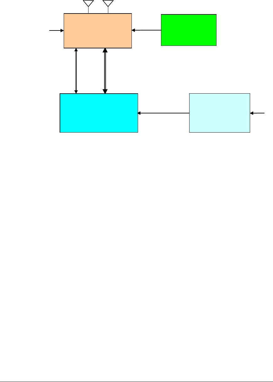
Figure 5 Translator Block Diagram
The Translator base system stores the encrypted Type Length Value (TLVs) messages in day
files. The log file name consists of a date stamp and 4 digit counter. At midnight, the current
day file is closed and a new file is opened with the new date stamp. To minimize Linux
resource issues while stress testing, a maximum number of records per log file is imposed.
When this maximum record count is reached, the current day file is closed and a new one is
open with the same date stamp but incremented counter. Multi-part messages are
reassembled and stored as a single day file entry for ease of retrieval. Remote command
pass-through sends the State of Health of the Seals, the Message ID and includes an initiation
of Wake on Radio sequence to the Seal. In addition, the day files also contain basic Translator
State of Health data such as the following:
• Translator up-time and RMSA application start / stop time.
• Date and time that messages are received by the Translator timebase (though not
necessarily the date and time the message was created by the Seal timebase).
• Number of successful and unsuccessful TLVs received from this Seal (based only on
properly formatted TLV Header information). See Figure 6 for a breakdown of the
TLV information and its proper formatting.
• Receive Signal Strength Indication (RSSI) / Link Quality Indication (LQI) based on
messages.
The Translator is considered a non-secure device as any stored seal data is encrypted at the
seal source before being collected by the Translator. However, Translator security features
are available including:
UNIVERSAL
AC
POWER
SUPPLY
ARM9 PC/104 SBC
TRANSLATOR
COMMUNICATION
CARD
(TCC)
PC/104
(ISA Bus)
TAMPER
DETECT
SWITCH
+ 5 VDC AC INPUT
ETHERNET
(POE)
ETHERNET
UNIVERSAL
AC
POWER
SUPPLY
ARM9 PC/104 SBC
TRANSLATOR
COMMUNICATION
CARD
(TCC)
PC/104
(ISA Bus)
TAMPER
DETECT
SWITCH
+ 5 VDC AC INPUT
ETHERNET
(POE)
ETHERNET
REMOTELY MONITORED SEAL ARRAY(RMSA)
SFG-MAN-001
REVISION: 1.7
2016 CANBERRA
10

• Password protection for upload of Translator log files to a review host via Samba.
• Translator log files are placed on a separate disk partition so problems with the root
partition will have no effect on the logs.
• An “rmsadeploy” script on the Translator that disables user access including
console/serial port access, ftp, ssh, etc. In deployed mode, the Translator’s SD card
(firmware) would have to be replaced to regain access.
• Improperly encrypted and authenticated data will be flagged by the Remote Review
GUI as “corrupt”.
Refer to Chapter 4 of this User’s Guide for more details on Translator operational deployment.
During RF transmissions, badly formatted TLV packets will be noted during the Translator’s
data review of the packets sent. All transmitted message data is stored on the Seal as well.
Interruption of network operations will not affect the Translator’s RF data store operations.
Network operations are only necessary during inspector download and review events.
Figure 6 shows the TLV message construction from the Physical Layer all the way up to the
Application Layer. The TLV message format is very flexible as it allows for new message types
to be created at some future point in time while allowing all previous message types previously
created to be fully backwards compatible.
The TLV format is set up with a Message Type Field (this it the “T”), followed by the Length
Field (this is the “L”) and then followed by the Value Field (this is the “V”). The Type and
Length fields are fixed in the number of bytes, but can be modified for future growth. The
Value field can be as long as feasible, depending on the Message Type.
REMOTELY MONITORED SEAL ARRAY(RMSA)
SFG-MAN-001
REVISION: 1.7
2016 CANBERRA
11
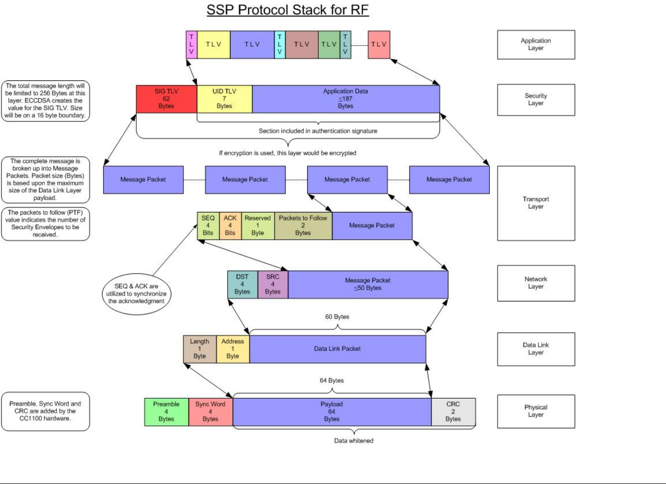
Figure 6 Type Length Value (TLV) Format
REMOTELY MONITORED SEAL ARRAY(RMSA)
SFG-MAN-001
REVISION: 1.7
2016 CANBERRA
12

1.5 RMSA Review GUI
The RMSA Review GUI application runs under Microsoft WindowsXP. The Review application
includes the ability to decrypt and authenticate Seal data and facilitates remote review of data
both in a batch processing mode and in a live update mode. Decryption and authentication of
the Seal data messages is provided as is handling of incorrectly formatted TLVs and batch
processing of multiple input files.
The RMSA Review GUI includes an Inspector Mode that provides a Main Batch Review
Screen and a Demand Data Screen. Within the Main Batch processing, a simplified view of
the data, a full view of the data, or a custom view may be set up by the inspector. The batch
processing of an RMSA day file(s) is only allowed with a password-protected Samba file share.
Figure 7 provides a diagram of how the Review Application Software may be used.
Should live data updates or Seal data queries be needed, a TCP/IP port connection to the
Translator is required. Query functions include either a request to acquire a specific Seal
message via a send message demand or a request for status via a State-of Health demand.
REMOTELY MONITORED SEAL ARRAY(RMSA)
SFG-MAN-001
REVISION: 1.7
2016 CANBERRA
13
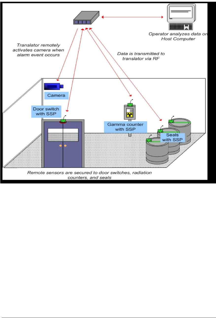
Figure 7 Example RMSA System Installation
REMOTELY MONITORED SEAL ARRAY(RMSA)
SFG-MAN-001
REVISION: 1.7
2016 CANBERRA
14

RMSA Set-Up
This chapter details the set-up steps for the RMSA system.
2.1 RMSA Seal Programming and Configuring
Ensure that the Seal has fresh batteries with the following instructions.
Chapter
2
REMOTELY MONITORED SEAL ARRAY(RMSA)
SFG-MAN-001
REVISION: 1.7
2016 CANBERRA
15
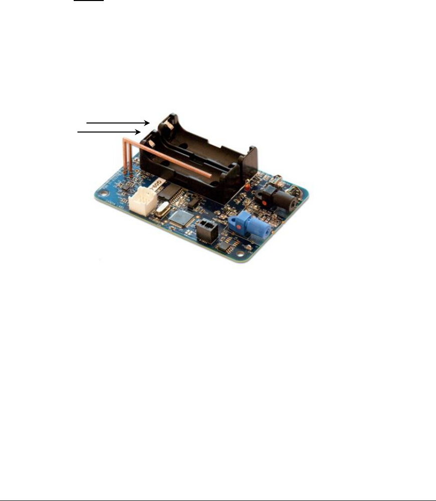
2.1.1 Changing the Seal Batteries
• Open the Seal case. See Figure 8 below, which just shows the Seal circuit card
assembly.
• The two 3.6-volt Lithium AA batteries are on the top of the board in battery holders.
• Remove old batteries and insert two fresh batteries. Note that the battery positive
terminal must align with where the arrows are pointing. There are also battery
orientation symbols in the battery holders.
• NOTE: The prototype Seal has a power switch which must be turned on (slide away
from the end of the board with the fiber optic cable ferrules) to enter the command
interface for personality programming.
• Reprogram the Seal personality, close the Seal case and install a fiber loop.
• Confirm proper start-up by verifying that the red LED visible through the bottom of the
Seal case flashes 5 times and then turns off.
Figure 8 Battery Holders (Seal Not in Case)
Battery
Holders for
Batteries
REMOTELY MONITORED SEAL ARRAY(RMSA)
SFG-MAN-001
REVISION: 1.7
2016 CANBERRA
16
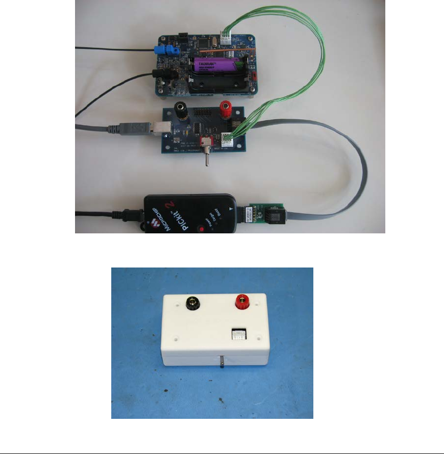
2.1.2 Programming the Seal
The picture below illustrates the hardware set-up for the Seal programming phase. In Figure 9
the Programming Card and Seal are outside of their respective cases while Figure 10 shows
the Programming inside its case. The hardware shown are the RMSA Programmer with USB
cable, an 8-pin cable to support the Seal console and a PICKit2 Programming Dongle with
USB-mini cable to support Seal microcontroller programming. The connections are the same
if an MPLAB ICD3 Programming and Emulation module is used instead of the PICKit 2. Both
USB cables (one from the PICKit 2 or ICD3 and one from the Programmer) are attached to the
host PC. The set-up for the Windows terminal program such as HyperTerm or TeraTerm to
be used with the Programmer Card is as follows: 8 data bits, No parity, 1 stop bit, 19.2 KBaud,
no flow control. Once the Seal has been properly configured and programmed, all dongle
connections may be removed and the Seal can operate stand-alone.
Figure 9 Out of Case Seal and Programmer Set -up
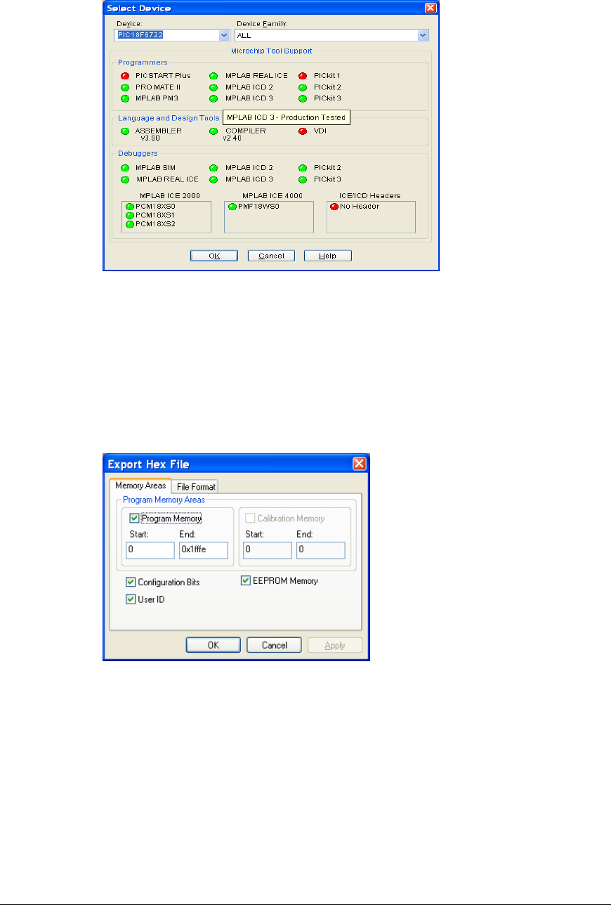
Figure 10 Seal Programmer Inside Case
REMOTELY MONITORED SEAL ARRAY(RMSA)
SFG-MAN-001
REVISION: 1.7
2016 CANBERRA
17

Note that support files have been packaged for the User in a folder called RMSA_USER_Files
in the support and documentation package provided with the RMSA system. The folder will be
referred to as the RMSA USER file repository in the remainder of this User Guide.
Seal programming requires access to MPLAB IDE version 8.43 or later and PICKit 2 version
2.61 or later. If programming is being performed using the MPLAB ICD3, the ICD3 is fully
supported by the MPLAB IDE. Both are available as free downloads from the Microchip
website at www.microchip.com. The MPLAB IDE is used to create the Seal hex code with
embedded Seal ID and then the PICKit 2 is used to write the hex file to the Seal. Each process
is described below along with the process to configure a Seal with the appropriate date and
encryption keys.
• Locate hex code files (will have a format such as NAME.hex) and Keys.dat in the
RMSA file repository. Also, locate the Seal personality Blind Programmer executable
in the RMSA file repository. (The default is typically C:\Program Files\Sandia National
Laboratories\SSP Software)
• Identify the host PC COM Port associated with the RMSA USB dongle (e.g., COM5 or
COM11). For the remainder of this User Guide, this COM port will be referred to as
Comport.
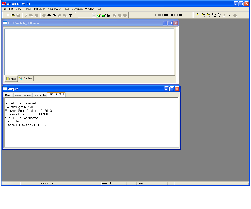
2.1.3 Creating the Seal-Specific Hex File with MPLAB IDE
To create a Seal specific .hex file (with embedded Seal ID), perform the following steps:
• Launch the MPLAB IDE application.
• Using the Configure/Select Device option, ensure that the MPLAB tool is configured
for device type PIC18F6722 as illustrated in the screen shot below:
Normal operation for the Seal should be 3.5 V, +/- 0.1 V. The Seal will operate between 3.0
and 3.6 volts.
IMPORTANT INFORMATION! Do not apply any voltage greater than 3.7 volts to the
Seal!
REMOTELY MONITORED SEAL ARRAY(RMSA)
SFG-MAN-001
REVISION: 1.7
2016 CANBERRA
18
• Under the File pull down, select Import. In the Open window, browse to the location of
the RMSA User files and select file FullUser.hex.
• Select Configure, then ID Memory, then enter the Seal ID (NOTE: All ID’s using 0xFF
in the least significant byte of the ID are reserved for the Translator only and may not
be used for Seal identification) in the User ID box, then press OK.
• Under the File pull down, select Export. Select the export defaults as illustrated below
and click OK.
REMOTELY MONITORED SEAL ARRAY(RMSA)
SFG-MAN-001
REVISION: 1.7
2016 CANBERRA
19
• In the Save As window, browse to the User file location and save the Seal specific
.hex file with a unique name. For example, if the new .hex file has embedded ID 6F,
save the .hex file as FullUser_ID6F.hex.
• If the Seal is to be programmed with the PICKit2 dongle, exit the MPLAB IDE
application and use the Writing the Hex File to the Seal with PICKit2 section.
Otherwise, remain in the MPLAB IDE and use the Writing the Hex File to the Seal
with ICD3 section.
2.1.4 Writing the Hex File to the Seal with ICD3
Writing the .hex file to the Seal requires the RMSA USB/Programmer. To write the .hex file to
a Seal, perform the following steps:
• Select a Seal, remove the enclosure and connect the RMSA USB/Programming
dongle and ICD3 dongle shown in Section 2.1 of this User Guide.
• Start the MPLAB Integrated Development Environment (IDE) if it is not already
running. The program will confirm the existence of the ICD3 programming module
and ask the user to confirm the correct power supply setting. When the initialization is
complete, the prompt will indicate that the program is ready. If not, check dongle
cabling (as shown in Section 2.1) and repeat this step until the connection is indicated.
REMOTELY MONITORED SEAL ARRAY(RMSA)
SFG-MAN-001
REVISION: 1.7
2016 CANBERRA
20
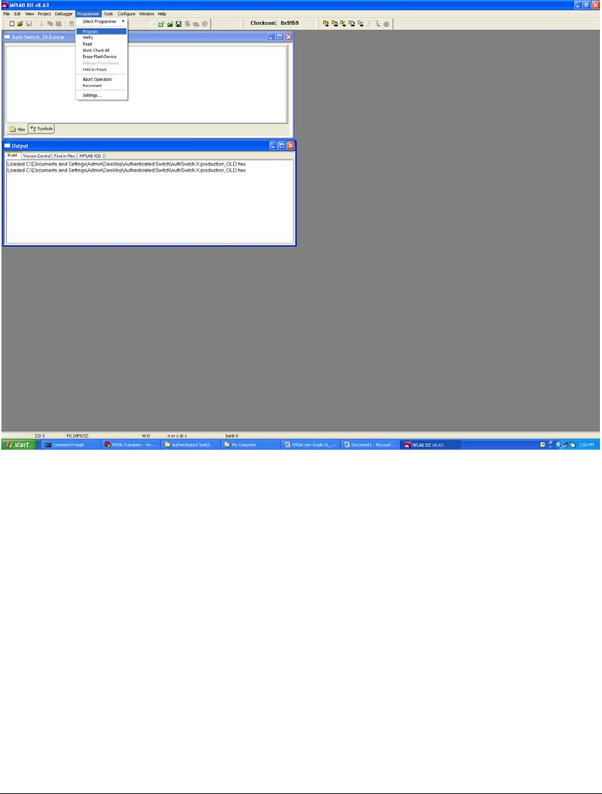
• Under the File pull down, select Import, browse to the Seal specific .hex file for the
Seal and select Open. The program will report the successful import of the hex file.
• Click Programmer from the top menu line and click on Program in the drop-down
menu
• The progress bar at the bottom of the screen will indicate that programming is in
progress, and the screen will report “Programming/Verify Complete” when it is
finished. Exit the MPLAB IDE program.
2.1.4 Writing the Hex File to the Seal with PICKit2
Writing the .hex file to the Seal requires the RMSA USB/Programmer. To write the .hex file to
a Seal, perform the following steps:
• Select a Seal, remove the enclosure and connect the RMSA USB/Programming
dongle and PICKit 2 dongle shown in Section 2.1 of this User Guide.
• Start the PICKit 2 application. Once started, the PICKit 2 window should indicate that
a PIC device was found. If not, check dongle cabling (as shown in Section 2.1) and
repeat this step until the connection is indicated.
REMOTELY MONITORED SEAL ARRAY(RMSA)
SFG-MAN-001
REVISION: 1.7
2016 CANBERRA
21
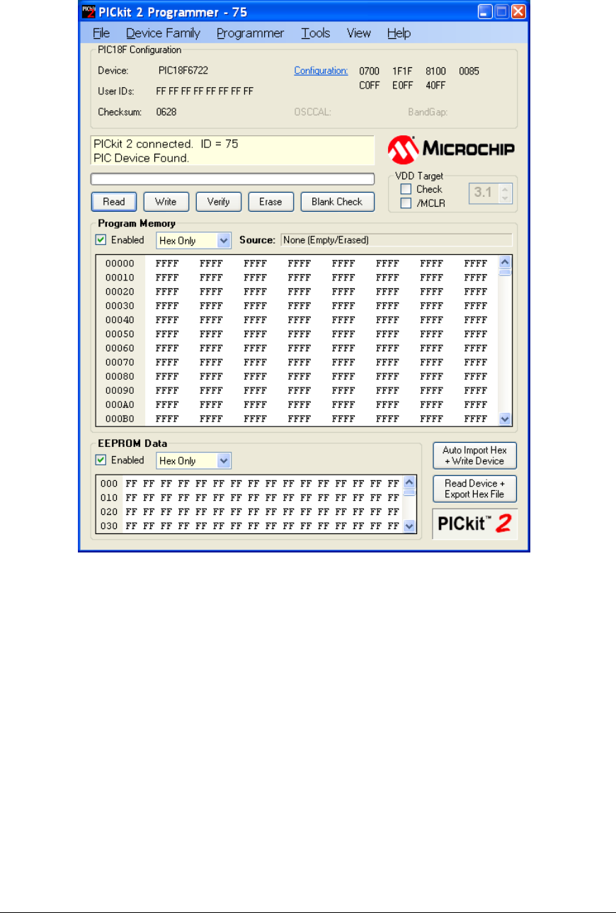
• Under the File pull down, select Import Hex, browse to the Seal specific .hex file for
the Seal and select Open. Note whether the program bytes appear in the Program
Memory window and if the message that the Hex file has been successfully imported
appears.
• Click the Write button. Writing the hex file to the Seal will take approximately 1 minute
allowing erase of the device then programming of the new code. A successful
outcome will cause the message box to be shaded green with the message
Programming Successful.
Note: Should the User wish to Read the code back, click the Read button. The message
“Reading Device: Program Memory” is displayed in the message box. After several
seconds, the message box will indicate it is “Done.”. No program bytes are available in the
Program Memory window (use ICD3 from Microchip).
2.1.5 The Key Files
Key files are used to load keys into the Seal with the Sandia National Laboratories Blind
Programmer GUI. The key files are for creation and review of encrypted and authenticated
Type Length Value (TLV) data. The key file is a table of comma-delimited records where each
REMOTELY MONITORED SEAL ARRAY(RMSA)
SFG-MAN-001
REVISION: 1.7
2016 CANBERRA
22

record contains the Seal ID followed by the default encryption key, encryption key and
authentication key. Key generation is dictated by IAEA policy and, therefore, outside the scope
of this User Guide. Example encryption keys for this step are obtained from key file keyfile.dat.
See Section 3.1 for information on how a Key file is generated for a series of RMSA Seal IDs.
REMOTELY MONITORED SEAL ARRAY(RMSA)
SFG-MAN-001
REVISION: 1.7
2016 CANBERRA
23
2.1.6 Configuring the Seal Personality
Sandia National Laboratories provides software for configuring seal personality including the
SSP Personality Profile Editor for creating an XML file to define SSP seal configuration and the
SSP Personality Programmer for programming the personality defined in an XML file into a
seal. Use the RMSA Software.msi installer program to install the tools on a host PC running
Windows XP. Then, from Start->All Programs, choose SSP Software to create the personality
XML file. Once created, the personality XML file can be used to configure any number of
seals. The XML file creation and SSP Programmer steps are described in more detail below.
The instructions below assume that the key file for the seals has been generated and is in a
known location.
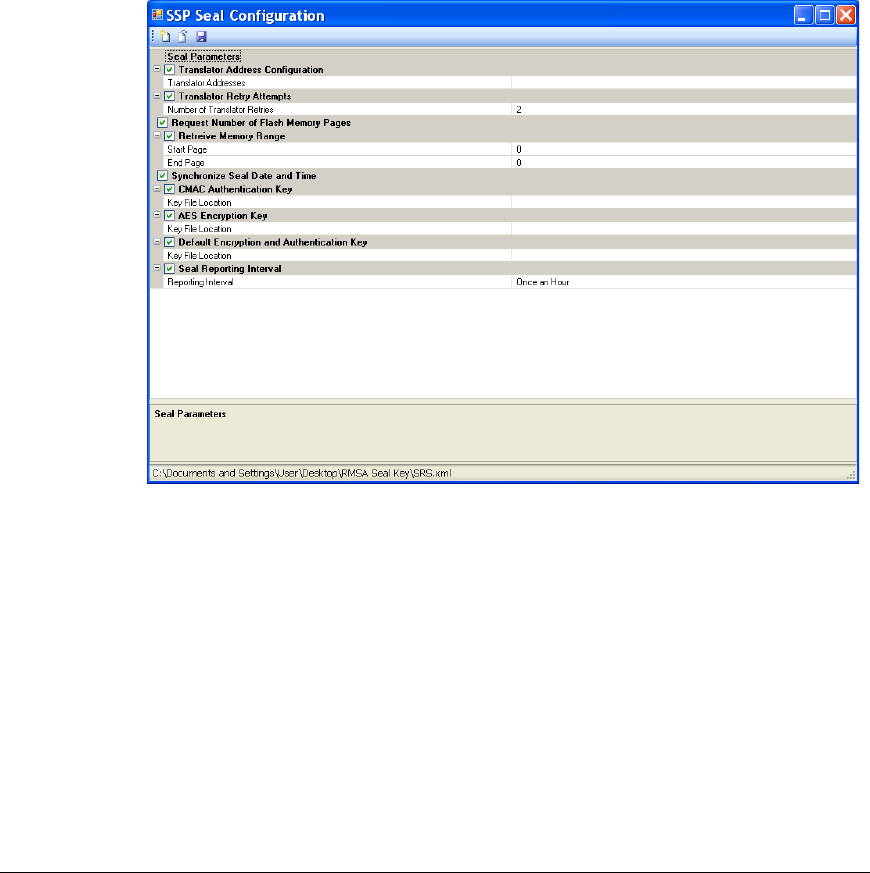
• Start the SSP Personality Profile Editor from Start->All Programs->SSP Software.
Just under the SSP Seal Configuration Title, click on the left most icon to create a new
configuration file. The configuration window should be similar to:
• Click the empty cell in the right column next to “Translator Addresses”. Enter the
default address 000000ff.
• Click anywhere on the “Key File Location” row for the CMAC Authentication Key then
click on the “…” icon that appears to the right of this row. Use the standard browser
interface to select the key file for the seals. Repeat this step for the “Key File Location”
row for the AES Encryption Key and Default Encryption and Authentication Key. Note
that these keys may be loaded from the same file.
• Click on the cells to the right of the label “Reporting Interval”. (The default value of
these cells is 30 seconds.) Enter any value between 30 seconds and 24 hours. This
interval defines the period for normal State of Health reporting for the seal.
• At this point, the configuration window should appear similar to:
REMOTELY MONITORED SEAL ARRAY(RMSA)
SFG-MAN-001
REVISION: 1.7
2016 CANBERRA
24
• Under the SSP Seal Configuration title, select the right-most icon to save the
personality configuration using the provided standard browser interface. Once saved,
exit the editor program.
• It is important that the RMSA programmer dongle be plugged into the host PC via a
USB port before starting the RMSA Blind Programmer GUI so that the GUI selects the
correct COM port for communications. Plug the RMSA Programmer dongle into the
USB port of the PC host and the white 8-pin connector into the seal.
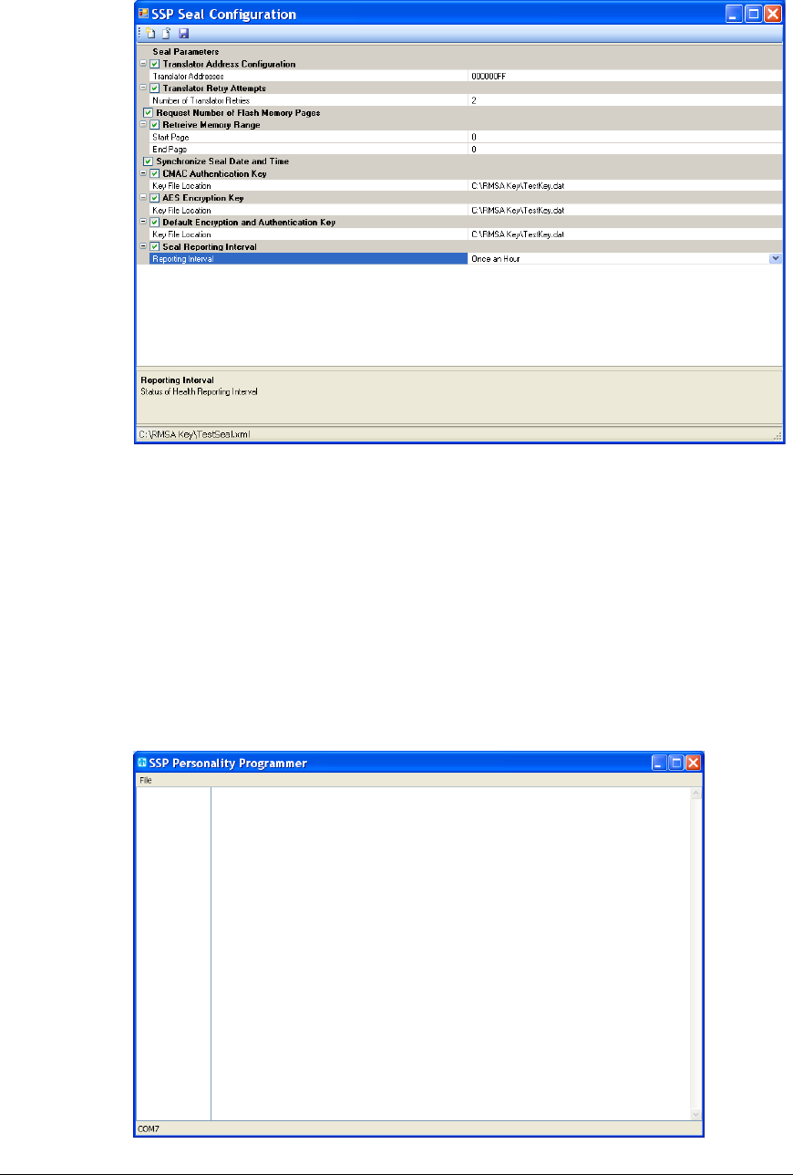
• Start the SSP Personality Programmer from Start->All Programs->SSP Software. In
the browser interface that is presented at startup, navigate to the XML configuration
file that you just saved. The SSP Programmer window will appear similar to:
REMOTELY MONITORED SEAL ARRAY(RMSA)
SFG-MAN-001
REVISION: 1.7
2016 CANBERRA
25
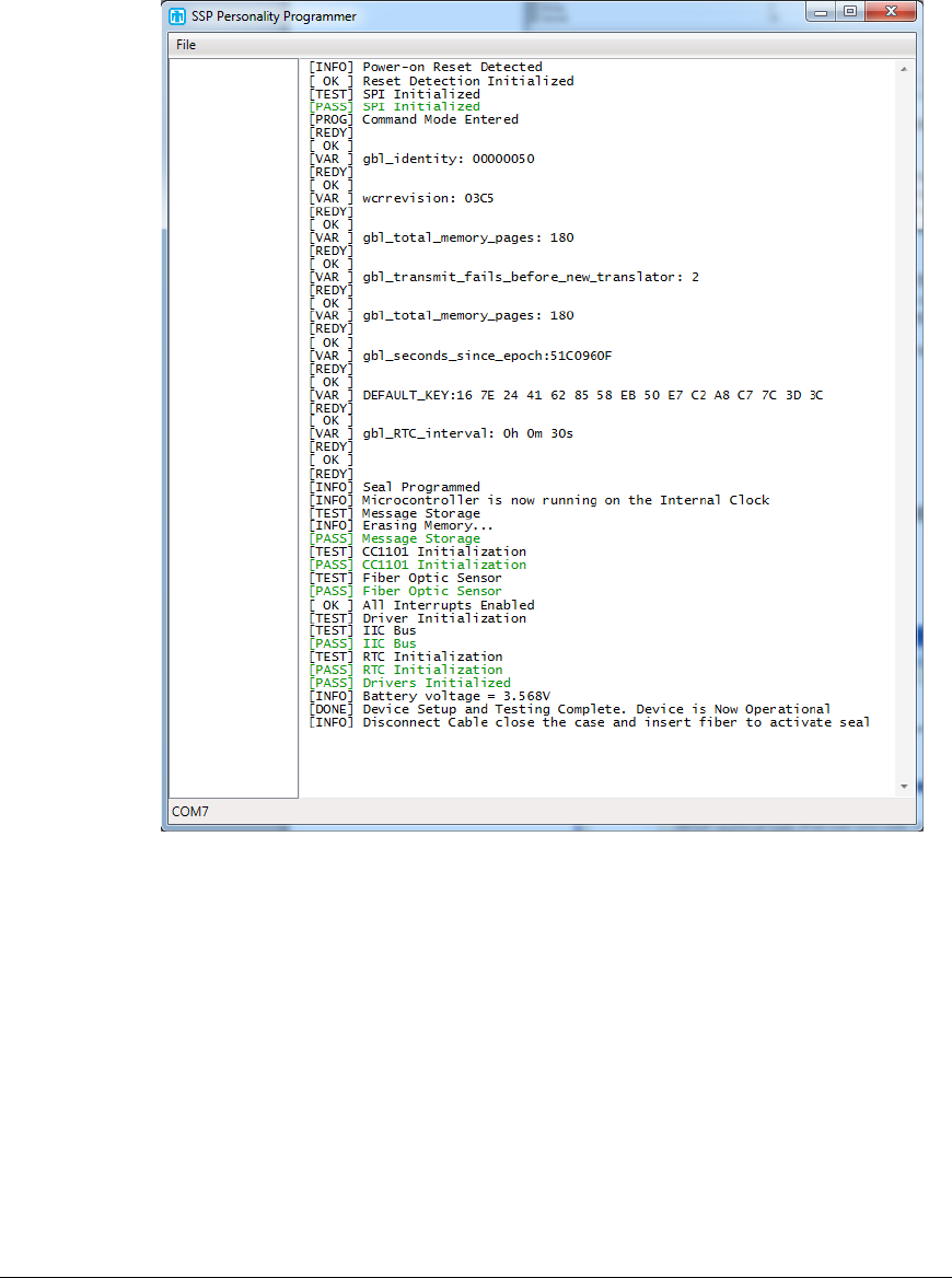
• Open the seal that is to be configured. Cycle the power (red switch) to the VDD
position. Message will appear in the Blind Programmer window reporting status of
seal configuration similar to:
• There should be no messages printed out in red font. Any such messages indicate
errors in the personality programming and/or the hardware.
• Disconnect the 8-pin programming connector from the seal and install the cover.
• When configuring multiple seals repeat the SSP Personality Programmer steps
above. (*The XML configuration file will need to be re-loaded for each seal.)
• At this point, the seals have been loaded with the information from the XML
configuration file:
• Translator Address
• Translator Retry Attempts
• Date and Time
• Authentication and Encryption Keys
• Seal Reporting Interval
REMOTELY MONITORED SEAL ARRAY(RMSA)
SFG-MAN-001
REVISION: 1.7
2016 CANBERRA
26

2.1.7 Verification of Seal Communications
Verification of seal communications requires an RMSA Translator. Refer to section 2.2.2
of this User’s Guide.
2.2 RMSA Translator Set-up and Linux Bootstrap
The Translator is initially delivered in factory set-up mode. In factory set-up mode, the
Translator is not yet installed in the tamper indicating enclosure and the User has access to the
Translator via the console port or secure network communication such as ssh. Section 4.1
includes Translator deployment steps which put the Translator in the more secure “deployed”
mode, eliminating console port access and auto-starting the RMSA application.
In factory set-up mode, an XP Windows PC can be used with a terminal emulator program
such as TeraTerm or Hyperterm to create a console connection to the Translator via an RS-
232 or USB port (with a USB-serial dongle). The console port should be configured with
115,200 baud, 8 bits, no parity, 1 stop bit and no flow control.
2.2.1 Translator Physical Configuration
To support the console port connection required for factory set-up mode, the Translator is
initially used in an open case or on the bench top. The Translator board stack consists of an
EmbeddedARM TS7800 SBC with Canberra’s custom TCC daughter card. Physical
configuration details for the Translator are as follows:
• TS7800 jumper JP1 is installed to initiate bootstrap from the SD card.
• TS7800 jumper JP3 is installed to run the CPU at 333MHz instead of 500MHz, saving
power and increasing reliability in extreme thermal conditions.
• A serial port console connection requires a null modem connector. A cross-over
Ethernet cable can be used to connect the Translator directly to the Windows-XP
Remote Review Host (see below).
• Two RF antennas should be connected to the TCC card through cabling in the
tamper-indicating enclosure.
• The tamper switch is connected to the Tamper port of the TCC card.
2.2.2 Creating a Translator SD Card
Translator initial factory set-up mode is achieved by creating a clone of a bootable Translator
SD card as documented in the “Cloning Translator SD Cards” section of the “Building RMSA
Software” document. This guideline contains a complete description of the cloning procedure.
Create a bootable SD card for the Translator as described below in a brief summary:
• Insert an SD card in an SD appliance connected to a Linux development environment.
These steps assume that the contents of the clonesd folder provided by Canberra is
installed in the Linux development environment in /home/rmsa/clonesd. This folder
should contain the tarclone.sh script, the tarballs for the RMSA root (root.tar.gz) and
home (home.tar.gz) partitions and the dd files for the other partitions required by the
REMOTELY MONITORED SEAL ARRAY(RMSA)
SFG-MAN-001
REVISION: 1.7
2016 CANBERRA
27

EmbeddedARM bootloader.
• Before proceeding, you must know the /dev file name for the inserted SD appliance.
This can typically be obtained from the dmesg utility. Make sure the SD appliance is
settled and available after insertion before continuing.
• From the shell prompt of the Linux development system, enter the following
commands:
cd /home/rmsa/clonesd
./tarclone.sh sdX
where sdX represents the /dev file name of the SD card appliance (which can be
determined from the dmesg utility).
• The disk clone procedure will take several minutes. Upon completion, dismount the
SD card from the appliance.
2.2.3 Booting the Translator
With power removed from the Translator, insert the bootable SD card into the Translator’s SD
card slot then apply Translator power. Linux bootstrap messages appear in the Translator
console window. The Translator is configured to auto-start the RMSA application. With no
active seals, the Translator bootstrap messages will be similar to:
>> TS-BOOTROM - built Dec 4 2008
>> Copyright (c) 2008, Technologic Systems
>> Booting from SD card...
.
.
.
.
>> Booting to SD Card...
INIT: version 2.86 booting
Starting the hotplug events dispatcher: udevd.
Synthesizing the initial hotplug events...done.
Waiting for /dev to be fully populated...done.
Cleaning up ifupdown...done.
Loading kernel modules...done.
Checking all file systems...
fsck 1.37 (21-Mar-2005)
... done.
/dev/tssdcardb6 on /home type ext3 (rw,noexec,nosuid,nodev)
Setting up networking...done.
Setting up IP spoofing protection: rp_filter.
Enabling packet forwarding...done.
Configuring network interfaces...done.
Starting portmap daemon: portmap.
INIT: Entering runlevel: 3
Starting system log daemon: syslogd.
Starting kernel log daemon: klogd.
Starting internet superserver: inetdJul 25 20:19:55 ts7800
kernel: Debian version TCC driver.
Jul 25 20:19:55 ts7800 kernel: Initializing TCCDriver: 0.0.1 @
IO base address 320
Jul 25 20:19:55 ts7800 kernel: TCC Card Version: -
(202D)<0>ID RT (5452)
Jul 25 20:19:55 ts7800 kernel: Registered device tcc, major #
REMOTELY MONITORED SEAL ARRAY(RMSA)
SFG-MAN-001
REVISION: 1.7
2016 CANBERRA
28

62
Jul 25 20:19:55 ts7800 kernel: CC1100 INIT: Success and ready
in RX mode.
Jul 25 20:19:55 ts7800 kernel: RxSyncLo = 91
Jul 25 20:19:55 ts7800 kernel: Verifying TCC Initial status:
<0> 02
Jul 25 20:19:55 ts7800 kernel: TCC driver successfully
initialized.
.
Starting Samba daemon......Samba daemon started!Starting
OpenBSD Secure Shell server: sshd.
Starting periodic command scheduler: cron.
main: Translator starting. Verbosity Level = LOW.
rmsa: Initializing log file.
rmsa: Initializing TCC.
tccInit: Opening /dev/tcc.
tccInit: TranslatorId=ff
tccInit: Wake Interval = 12 msec, Wake Duration = 5 msec
tccInit: Initializing known device queue at 0x16610.
tccInit: SSPq ready. tccInit: radioCfg=0
tccInit: channel number = 0x0main: Ready to service TCC port.
rmsa: Initializing CC1100.
Jul 25 20:20:02 ts7800 kernel: CC1100 INIT: Success and ready
in RX mode.
Kernel level CC1100 INIT returns 1.
Disable all TCC interrupts returns 1.
cc1100: Programming CC1100.
Setting cc1100Ready to 1
CC1100 programming successful.
Flushing the RX FIFO returns 1.
Flushing the TX FIFO returns 1.
Calibrating.
Calibration returns 1
Entering RX Mode.
RX mode returns 1
CC1100 Ready.
rmsa: Starting threads.
netCreateSocket: translator hostname: ts7800
netCreateSocket: Creating network socket ...
net create socket, sockfd = 7
netCreateSocket: Network socket ready. Bind=0
rmsa: Logging application start.
logTranslatorEvent: Logging translator event 0.
rmsa: Enabling TCC interrupts.
rmsa: Radio channel number: 0x0
main: Translator successfully initialized.
Set process priority to -10
Calling tccServicePort with priority -10
2.2.4 Setting Translator Time
To configure the Translator system time, Login as User “root” with password “rmsa”. This can be
done from the console port or via a ssh connection from a Linux host. If the console is required,
we must first terminate the RMSA application. To do this, enter CTRL C on the console port.
Within 7 seconds, you must enter the root user name and password then issue the command
wdoff. If the wdoff command is not issued within 7 seconds, the watchdog timer will expire
and the Translator will reboot.
REMOTELY MONITORED SEAL ARRAY(RMSA)
SFG-MAN-001
REVISION: 1.7
2016 CANBERRA
29

From the shell prompt, issue the following command to set the Translator system time:
date –u MMDDhhmmCCYY.ss
Where –u is the command line argument that specifies UTC format and
MM represents the current month (01-12)
DD represents the current month day (01-31)
hh represents the current hour (01-23)
mm represents the current minute (01-59)
CCYY represents the current year (e.g. 2010)
and ss represents the seconds (01-59)
Repeat this step as often as necessary until satisfied with the new system date and
time, the new date and time is repeated on the console without error and the shell
prompt is re-displayed. For example:
# date –u 011208272010.45
Tue Jan 12 08:27:45 MST UTC 2010
#
If the RMSA application was terminated in order to use the Translator console, restart the
RMSA application with the following command:
rmsa -v
Alternatively, the application can be restarted by rebooting the Translator.
2.2.5 Verification of Translator Operation
An operational Translator running the RMSA application will automatically collect and store the
Seal messages. The Translator receives and stores Seal messages, and logs them
chronologically (in the order received) in day files in a separate partition on the SD card from
the root file system. The size of the storage for messages is 1.5GB or larger.
Translator Implementation Note: All Translator statistics and message logs are stored in files
on the Translator SD card. As disk files, the logs are non-volatile. Separate file partitions are
provided for system and message logs. System status information is in the root partition. The
size of the root /home partition depends on the size of the SD card. Approximately 512 MB are
used for bootloader and root partitions. A 2GB SD card, for example, would have
approximately 1.5GB available for the message log partition.
In order to verify Translator operation, prepare at least 2 seals according to the instructions in
Section 2.1 of this User’s Guide and operate the Translator in factory configuration mode with a
console cable attached. With the seals configured and installed, reboot the Translator and
observe the bootstrap messages in the console window followed by the RMSA application
initialization messages as described in section 2.2.3, above. If the seal period is set to one
minute, then within one minute you should see messages similar to the following:
tccServicePort: Rcvd 63 bytes from 45 seq_ack 31
tccRegisterDevice: creating new SSPq entry for 45
sspReceive: ACKing 45 SSP with seq_ack byte 33
tccSend (14): 0D 45 00 00 00 45 00 00 00 FF 33 00 00 00
tccServicePort: Rcvd 43 bytes from 45 seq_ack 43
sspReceive: ACKing 45 SSP with seq_ack byte 44
REMOTELY MONITORED SEAL ARRAY(RMSA)
SFG-MAN-001
REVISION: 1.7
2016 CANBERRA
30

tccSend (14): 0D 45 00 00 00 45 00 00 00 FF 44 00 00 00
Cleared 2 segments for device 45
Note: In this example, 45 is the Seal address that originated the message. Similar messages
should appear for other Seals.
Verification of seal message logging can be accomplished by logging into the Translator.
Once again, if the console must be used, it will be necessary to CTRL C, log on to the
Translator as root and issue the wdoff command within 7 seconds. Alternatively, use an ssh
network connection. From the shell prompt (“#”) within the console window, issue the
following commands:
cd /home/share
ls
Verify log file contents with the command:
cat filename
where filename is a log file name such as rmsa255_20100112.log.
The log file will contain entries that look similar to the following example:
1, 2010 01 15 17:10:47, 00000051, 00000032, 00000000, 000000FF,
0 06:43:22, 1, ab(a9/ab), 00(00/00), 80, fb 1c a7 b5 55 a4
d1 69 22 f5 67 be 1c 09 c1 82 ec 79 59 ec de 6d a1 a2 32 44 22 8e
1b b2 34 62 7b 45 4c 35 e2 d2 1c 43 04 1b ba 1e 3b ce d4 dd fe 63
57 25 93 e2 3d b0 ea 95 35 a6 0f bc 24 ea 03 4d 02 e3 5e b7 3b c6
69 5d dc 40 c7 3d 5c 55
Highlights have been added to the example log entry above to facilitate understanding of this
comma separated data file:
The green text is the log entry type. 1 indicates a message received. (Other log entry types
indicate Translator start, Translator tamper, etc.)
The yellow text is the timestamp that the message was received. A review of the log file
(using cat or similar linux tool) will show the entries in chronological order based on this time
stamp.
The non-highlighted text contains a snapshot of key Translator statistics at the time the
message was received.
The pink text is the number of message bytes received.
The cyan text contains the actual as-received encrypted message bytes. The TLV contents
are not available to the Translator in clear-text.
From the shell prompt, issue the following command to display Translator file partitions:
df
Results will be similar to:
REMOTELY MONITORED SEAL ARRAY(RMSA)
SFG-MAN-001
REVISION: 1.7
2016 CANBERRA
31

Filesystem 1K-blocks Used Available Use% Mounted on
tmpfs 63584 … … 0% /dev/shm
/dev/tssdcardb6 2855172 … … 3% /home
tmpfs 10240 … … 1% /dev
Note that /home is mounted as a separate file partition completely separating the storage for
the RMSA log files from system information and statistics.
2.2.6 Translator Power-Over-Ethernet Operation
To configure the Power-Over-Ethernet option, disconnect the AC power cord from the
Translator and connect POE enabled power supply or POE enabled Ethernet Router to the
Translator with an Ethernet cable. To verify correct operations, apply Translator power and
verify the bootstrap messages in the console window as described in section 2.2.3 of this
User’s Manual.
Note that the Translator can be powered simultaneously from either the POE interface or the
AC interface without any issues.
2.2.7 Alternate Translator Configuration
The default Translator SSP address is 0xff and the default radio channel is 0. These settings
should be adequate in most cases. Instructions are provided below for applications where
these default settings must be modified.
The default radio frequency of the Translator is set correspond with the base of the proper
allocated frequency band and to agree with the frequency that is programmed into the Seals.
While the channel of the Translator may be changed, it must agree with the channel that the
Seals are operating on to insure proper communication. The Translator channel should only
be changed if the Seals have been programmed with an alternate channel. To change the
default radio channel, edit the file /etc/rmsa/radioconfig and replace the 0 with the desired radio
channel. The radio channel value may range from 0-30 hexadecimal.
To change the Translator’s SSP address, edit the file /etc/rmsa/transid and replace the ff with
the desired translator address. The Translator address may be any hexadecimal integer (4
bytes) where the last byte is either ff or 0.
Note that the /etc/rmsa folder contains 2 other files that should not be modified. The sdVersion
file may be read to obtain the translator software version. The wakecfg file was used by
developers to experiment with the command and acknowledge timing for demanding seal data
and should not be changed.
2.2.8 Change Translator IP Address
To change the translator IP address, connect to the translator via the console port. The 4
steps below must be performed within 7 seconds or the watchdog will cause the system to
reboot.
Type Ctrl + c
ts7800 login: root
Password: rmsa
root@ts7800:root# wdoff (enter)
REMOTELY MONITORED SEAL ARRAY(RMSA)
SFG-MAN-001
REVISION: 1.7
2016 CANBERRA
32

At this point the root@ts7800:root# prompt should be displayed.
Edit the Hosts file
root@ts7800:root# cd /etc (enter)
root@ts7800:etc# vi hosts (enter)
The "hosts" file will be open for editing.
10.10.16.72 ts7800 <--Change to the desired IP address
127.0.0.1 ts7800
204.152.191.39 ftp.us.debian.org
130.225.242.102 ftp.sunsite.dk
10.10.16.71 yagoo
# The following lines are desirable for IPv6 capable hosts
# (added automatically by netbase upgrade)
::1 ip6-localhost ip6-loopback
fe00::0 ip6-localnet
ff00::0 ip6-mcastprefix
ff02::1 ip6-allnodes
ff02::2 ip6-allrouters
ff02::3 ip6-allhosts
~
To add new characters place the cursor under the character(s) that will be changed and press
"i", type the desired character(s) and press "esc". To Delete old characters place the cursor
under the characters(s) that need to be removed and press "x". When changes are complete
press "shift+z+z" to close and save the file.
Edit the Interfaces file
root@ts7800:root# cd etc/network (enter)
root@ts7800:network# vi interfaces (enter)
The "interfaces" file will be open for editing.
#Used by ifup(8) and ifdown(8). See the interfaces(5) manpage
or # /usr/share/doc/ifupdown/examples for more information.
auto lo
iface lo inet loopback
auto eth0
#iface eth0 inet dhcp
iface eth0 inet static
address 10.10.16.72 <--Change to the desired IP address
network 10.10.16.0 <--Change to the desired network (if necessary)
netmask 255.255.255.0
broadcast 10.10.16.255
gateway 10.10.16.72 <--Change to the desired gateway
# address 192.168.239.50
# network 192.168.239.0
# netmask 255.255.255.0
# broadcast 192.168.239.255
# gateway 192.168.239.1
#iface eth0 inet static
# address 192.168.1.207
# network 192.168.1.0
# netmask 255.255.255.0
REMOTELY MONITORED SEAL ARRAY(RMSA)
SFG-MAN-001
REVISION: 1.7
2016 CANBERRA
33

interfaces: unmodified: line 1
To add new characters place the cursor under the character(s) that will be changed and press
"i", type the desired character(s) and press "esc". To Delete old characters place the cursor
under the characters(s) that need to be removed and press "x". When changes are complete
press "shift+z+z" to close and save the file.
When all changes are complete the system will need to be re-booted.
root@ts7800:network# reboot (enter)
REMOTELY MONITORED SEAL ARRAY(RMSA)
SFG-MAN-001
REVISION: 1.7
2016 CANBERRA
34

RMSA Key Generation
This chapter demonstrates key generation for the Seal.
3.1. RMSA Key Generation
This step uses software that runs in a DOS box on a WindowsXP PC generating keys for one
Seal. The resultant keys will be loaded into the Seal.
• Locate the file rmsakeyfilegen.exe in the RMSA file repository.
• Note that Help is available if needed in the following file:
msakeyfilegenhelp.txt
• Start the key generation software by typing the following command line in the DOS
box:
rmsakeyfilegen.exe /start:0x00000001 /end:0x000000FF /keyfile:rmsakeys.dat
/start tells the generator what the first RMSA Seal ID in the file will be. Additional
Seal IDs will increment from this one.
/end tells the generator what the last RMSA Seal ID in the file will be.
/keyfile tells the generator the filename to write the keys to.
• You will be prompted to retype in a first set of specific random characters in the DOS
box. Type in the first set of characters.
• You will be prompted to retype in second set of specific randomly characters in the
DOS box. Type in the second set of characters
• You will be asked to type in 128 random key strokes. Type in 128 keystrokes.
• After the 128th keystroke, the program will ask the User to stop typing and will create
the keyfile.
Chapter
3
REMOTELY MONITORED SEAL ARRAY(RMSA)
SFG-MAN-001
REVISION: 1.7
2016 CANBERRA
35
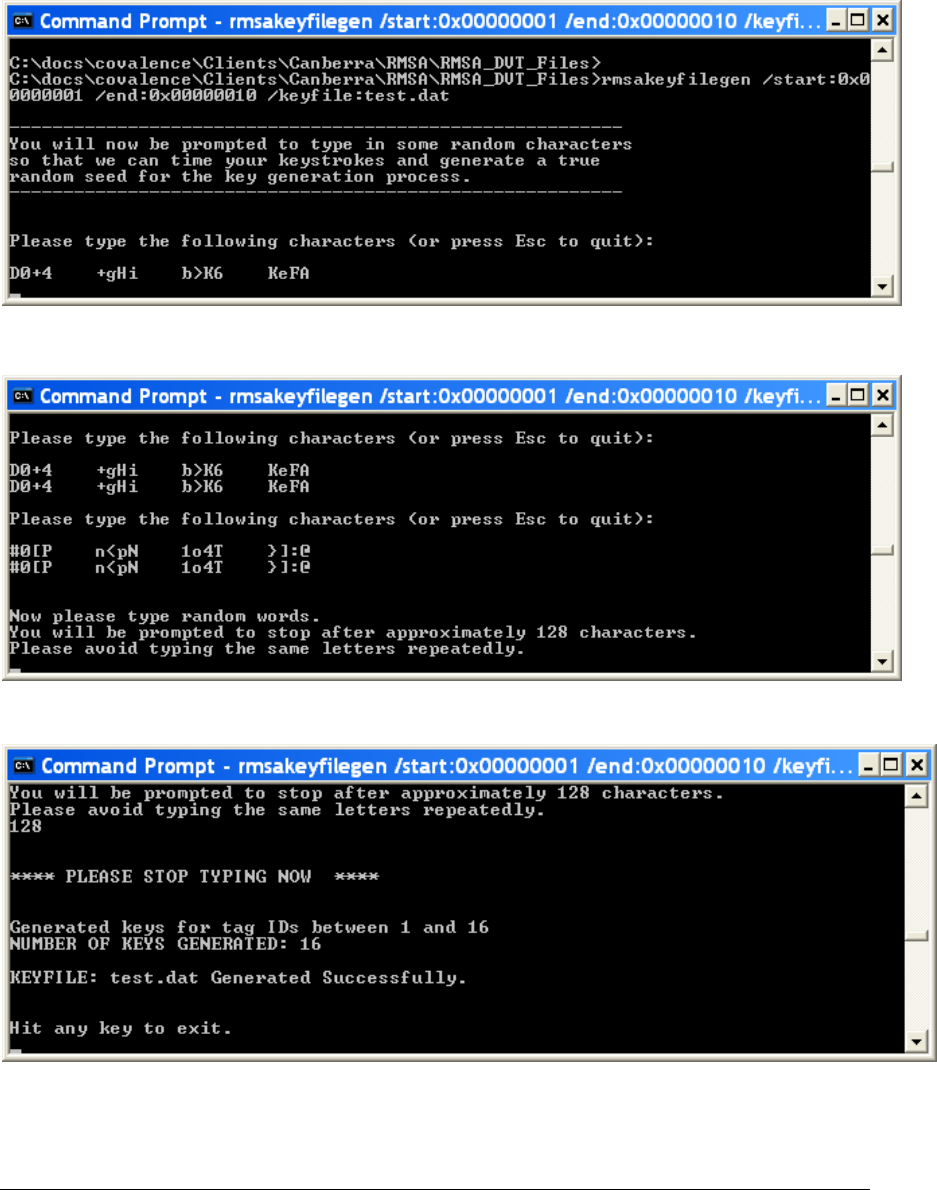
Starting the Key Generation Software
After echoing 2 sets of characters by the key generation software
After entering 128 keystrokes
The keys have been generated in the named file. You can close the DOS box.
REMOTELY MONITORED SEAL ARRAY(RMSA)
SFG-MAN-001
REVISION: 1.7
2016 CANBERRA
36

RMSA Security
This chapter demonstrates RMSA encryption, authentication and
default keys as well as adding new fiber lengths to a Seal.
4.1 Collect / Store Seal Messages with no Console Access
The Translator provides a script for deploying from factory set-up mode to operational mode.
In operational mode, no further access to the Translator (via the physical console or secure
network communications such as ssh or sftp) will be possible. To re-use the Translator in
factory set-up mode, the User will have to configure a new bootable SD card as described in
Section 2.2 of this User Guide.
To deploy a Translator into operational mode, from the shell prompt in the console window,
issue the command:
rmsadeploy
Messages similar to the following will be displayed on the in the console window:
Cleaning files out of the /home/share directory ...
Cleaning debug statistics in /var/stat/rmsa ...
Disable root login...
Removing ssh service...
Remove unnecessary modules...
Disable root ftp access ...
Autostart RMSA application ...
Removing TTYs and console...
Deploy complete.
Rebooting Translator to implement security changes.
Remove the Translator console cable and install the enclosure cover.
4.2 Authentication and Encryption of Messages
Valid keys are necessary for decryption and signature verification. Key management
procedures, including generation of keys and key file management, are the responsibility of the
user.
Messages with invalid authentication keys will result in a “Bad signature” message status in the
RMSA Review GUI. Messages with invalid encryption keys will result in a “Bad key” message
status in the RMSA Review GUI and the decrypted data will not be available for review.
Messages with a correct encryption and authentication key will be available for review in the
Chapter
4
REMOTELY MONITORED SEAL ARRAY(RMSA)
SFG-MAN-001
REVISION: 1.7
2016 CANBERRA
37
RMSA Review GUI. When messages are properly decrypted and authenticated, all TLV data
is displayed.
• Ensure that the RMSA Review Application is connected to the Translator by noting
that the RMSA Review Application indicates it is connected and new messages from
the Seals appear in the main display at a rate that has been configured by the User in
Section 2.1.7.
• Open the key file keyfile.dat in the RMSA file repository.
• Note that for each Seal ID is defined 3 keys. The first is the default key, the 2nd is the
encryption key, the 3rd is the authentication key. An example for a hypothetical entry
for Seal ID 50 could show:
Default key: FAAB136723F5DD237533C32A14879011
Encryption key: 2086C23014C770D7411C039028740150
Authentication key: 2B7E151628AED2A6ABF7158809CF4F50
• Quit (Don’t Save) the keyfile.dat file.
4.3 Fiber Lengths
This step is to demonstrate how to use various fiber lengths. The User may add any User
selected length of fiber, between 1 and 30 meters cut from a spool of fiber without any special
tools. However, it should be noted that the best way to ensure a good plastic optical fiber
(POF) connection to the Seal would be to use a very sharp implement that will create a clean
cut that is orthogonal to the cable. Cuts that have angles, are ragged or are poorly terminated
will affect the sensitivity measurements done by the Seal for the light intensity and can preclude
proper operation if not enough light is coupled through the fiber.
After each fiber insertion or removal, the Seal will send a message that shows the state of the
fiber link in the Seal (i.e., Open or Closed).
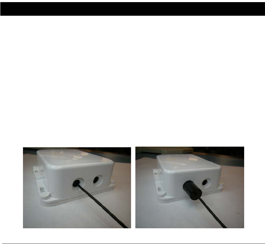
• Insert the fiber within the RMSA Seal ferrules and then screw down until Hand Tight.
(DO NOT OVER-TIGHTEN!)
o Push the POF into the opening until you feel it bottom out against the
photodiode. Hand-tighten the ferrule
Figure 11 Installing Plastic Optical Fiber (POF)
REMOTELY MONITORED SEAL ARRAY(RMSA)
SFG-MAN-001
REVISION: 1.7
2016 CANBERRA
38

o Repeat the above sequence for the other end of the POF for the remaining
fiber opening in the Seal.
o To remove the POF, do the same set of operations but in reverse order.
• Ensure that the RMSA Review Application is connected to the Translator (see section
5.1) by noting that the RMSA Review Application indicates it is connected and new
messages from the Seals appear in the main display at a rate of that has been
configured by the User in Section 2.1.6.
• Remove one end of the POF from the seal.
• Within a few seconds, a message is displayed from that Seal indicating an alarm
under the Source Tamper Status column, indicating that a fiber has been removed or
inserted.
REMOTELY MONITORED SEAL ARRAY(RMSA)
SFG-MAN-001
REVISION: 1.7
2016 CANBERRA
39
Remote Review of Seal Data
This chapter describes the installation, configuration and use of the
demonstration RMSA Remote Review GUI provided by Canberra for
the analysis of data collected by the Translator.
5.1 RMSA Review GUI Installation and Configuration
The RMSA Review GUI installer is provided by Canberra in the RMSA repository. The
demonstration GUI runs on a Windows XP PC. The default installation location of the GUI will
be in c:\Program Files\RMSA. The GUI is based on the .NET framework which must be
installed before installing the RMSA Review GUI. If required, a copy of the .NET framework is
also provided by Canberra in the RMSA repository.
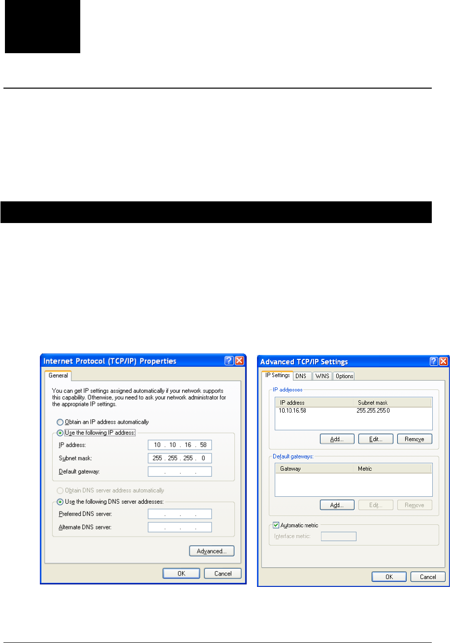
The demonstration RMSA Review GUI relies on a network connection from the Windows XP
host to the Translator. This can be accomplished with an Ethernet crossover cable from the
PC to the Translator with the PC LAN port configured as follows:
Once the LAN is properly configured, it should be possible to ping the Translator (default IP
10.10.16.72) to confirm the network connection.
Chapter
5
REMOTELY MONITORED SEAL ARRAY(RMSA)
SFG-MAN-001
REVISION: 1.7
2016 CANBERRA
40

5.2 Loading Collected RMSA Data
The RMSA Review GUI is designed to work in two ways:
• In Remote Review Mode the GUI loads one or more day files from the Translator’s
Samba-mounted /home partition for review and analysis.
• In Local Host Mode an active network connection is made between the RMSA
application running on the Translator and the Remote Review GUI. In this mode, as
seal messages are received by the Translator and stored in a day file, the messages
are also sent immediately to the GUI providing a “live” view of RMSA message activity.
In local host mode, the GUI operator can also demand seal data by requesting an
immediate State-of-Health (SOH) message or a resend of a previous seal message.
In both modes, the GUI controls the number of records loaded for review in order to avoid
resource issues on the Host PC. Operating procedures for each mode are further described in
the remainder of this section as is the procedure for configuring the maximum number of
records available for viewing. Operating procedures for data analysis and for demand of seal
data are provided in sections 5.3 and 5.4 of this chapter.
Both Remote Review and Local Host operations require the GUI operator to have access to
the same key file(s) used to configure the seal personality in order to properly decrypt and
authenticate the seal data.
5.2.1 Remote Review Operation
Perform the following steps to operate the RMSA Review GUI in Remote Review mode:
• Ensure the Translator is operational and a PC LAN connection has been established
between the Host PC and the Translator (refer to section 5.1, above).
• Establish the Samba connection between the Host PC and the Translator using the
Tools->Map Network Drive function in an Explore window. The drive folder will be
\\10.10.16.72\share. Click on Connect Using a Different Username and enter
Username “smbuser” and password “asdfqwer”. (Note that this factory default
password can be changed by the user prior to Translator deployment.)
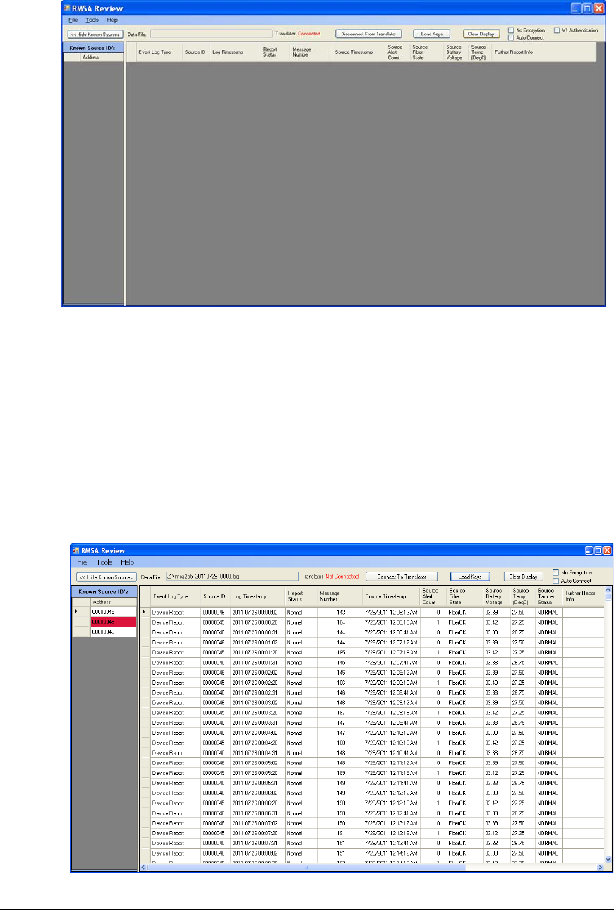
• Start the RMSA Review GUI via Start->All Programs->RMSA Review. A window
similar to the following should appear:
REMOTELY MONITORED SEAL ARRAY(RMSA)
SFG-MAN-001
REVISION: 1.7
2016 CANBERRA
41
• Click the Load Keys button, then browse for the appropriate key file. Double click the key
file (keyfile.dat, for example) to load the keys. A message box will be displayed indicating
that the key file was successfully loaded. Click OK to dismiss this message.
• Using the File pull-down in the toolbar (upper left corner), browse for a log file on the
Translator’s Samba-mounted drive. Double click on one or more day file to upload that
day’s data to the remote review GUI.
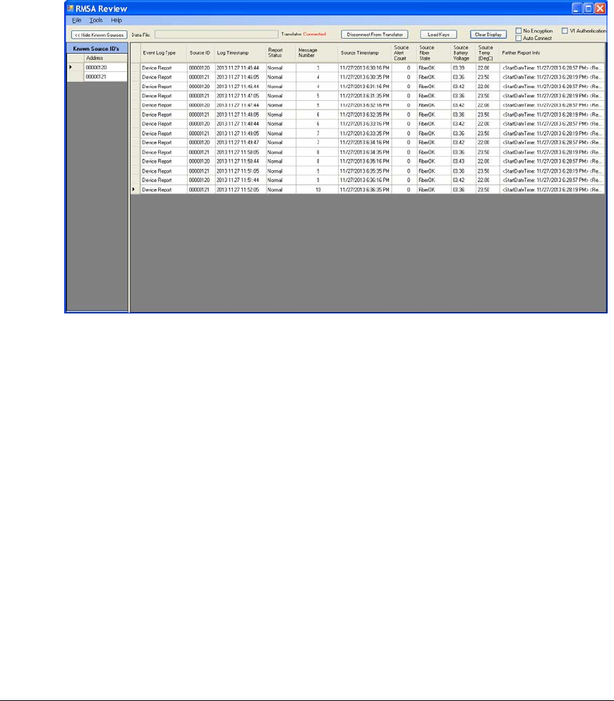
• Data is displayed in the GUI similar to the example below. Note the file name in the Data
File text box at the top of the display. If more than one file is selected for loading, this text
box will contain the name of the last file loaded but the main window will contain the data for
all files.
REMOTELY MONITORED SEAL ARRAY(RMSA)
SFG-MAN-001
REVISION: 1.7
2016 CANBERRA
42
5.2.2 Local Host Operation
Perform the following steps to operate the RMSA Review GUI in Local Host mode:
• Repeat all steps for Remote Review operation up to the point of select day files with the
File pull down. I.e., start the RMSA Review GUI and load keys.
• Click the Connect to Translator button. Within a few seconds, the Translator status
should be changed from Disconnected to Connected and the button will be relabeled
“Disconnect From Translator”. As seal messages are received by the Translator, they
will be immediately sent to the GUI. Refer to the view below:
To terminate the Local Host connection, click on the Disconnect From Translator button. For
best synchronization of the network connection between the GUI and Translator, the
connection should be disconnected before terminating the RMSA Review application. If not, it
may take several minutes to re-establish the connection if the GUI restarted.
In Local Review mode, demanding seal data is available via the Tools pull down as described
in section 5.4.
In Local Host mode, a TCP/IP connection heartbeat message is passed between the GUI and
Translator. If loss of heartbeat is detected, the connection will be shutdown. If this occurs, the
Translator status will change to Disconnected and the button will be relabeled “Connect to
Translator.
Note the Auto Connect option near the upper right corner of the display. If this option is
selected, the GUI will automatically attempt to establish GUI/Translator communications.
Therefore, if a network disruption causes disconnection due to loss of heartbeat, the GUI will
re-establish the connection within a minute once the network becomes available.
REMOTELY MONITORED SEAL ARRAY(RMSA)
SFG-MAN-001
REVISION: 1.7
2016 CANBERRA
43
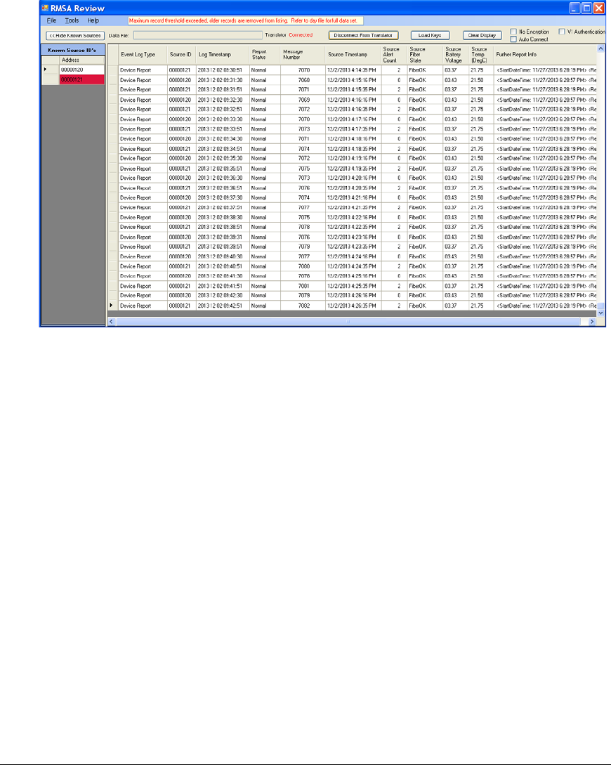
5.2.3 Maximum Record Display Threshold
If the number of total number of records for all day files exceeds the maximum record count for
the RMSA Review Display, a warning will be printed at the top of the display indicating that the
maximum record threshold has been exceed as illustrated below. Consider loading fewer day
files to view the complete set of data. If a particular day file exceeds the maximum record count,
consider raising the threshold or using an editor to break the day files into multiple parts.
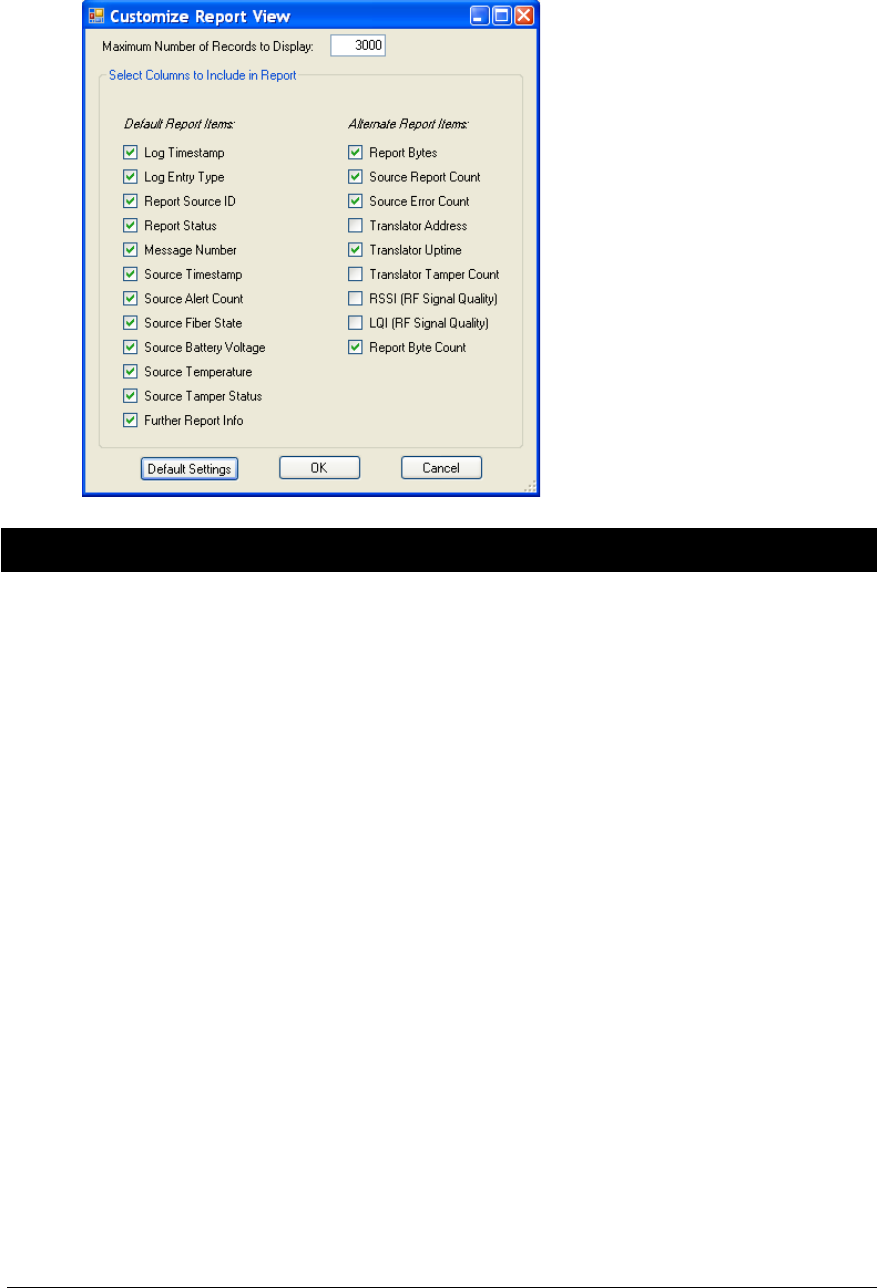
To increase the threshold, select Tools->Customize Report View. The threshold setting is in
the Maximum Number of Records to Display box at the top of the configuration menu
(illustrated below). Change the setting as desired and click OK. Data will need to be reloaded
(from the File pulldown) to load additional records. The default value of the threshold is 1000.
REMOTELY MONITORED SEAL ARRAY(RMSA)
SFG-MAN-001
REVISION: 1.7
2016 CANBERRA
44
5.3 Sorting and Analyzing RMSA Data
This section summarizes the methods available in the demonstration RMSA Review GUI for
sorting data or generating alternate data view to assist with analysis. The details of the default
data view, device-specific reports and data view customization are provided below.
5.3.1 Default Data View
The RMSA Review default data view is illustrated below.
REMOTELY MONITORED SEAL ARRAY(RMSA)
SFG-MAN-001
REVISION: 1.7
2016 CANBERRA
45
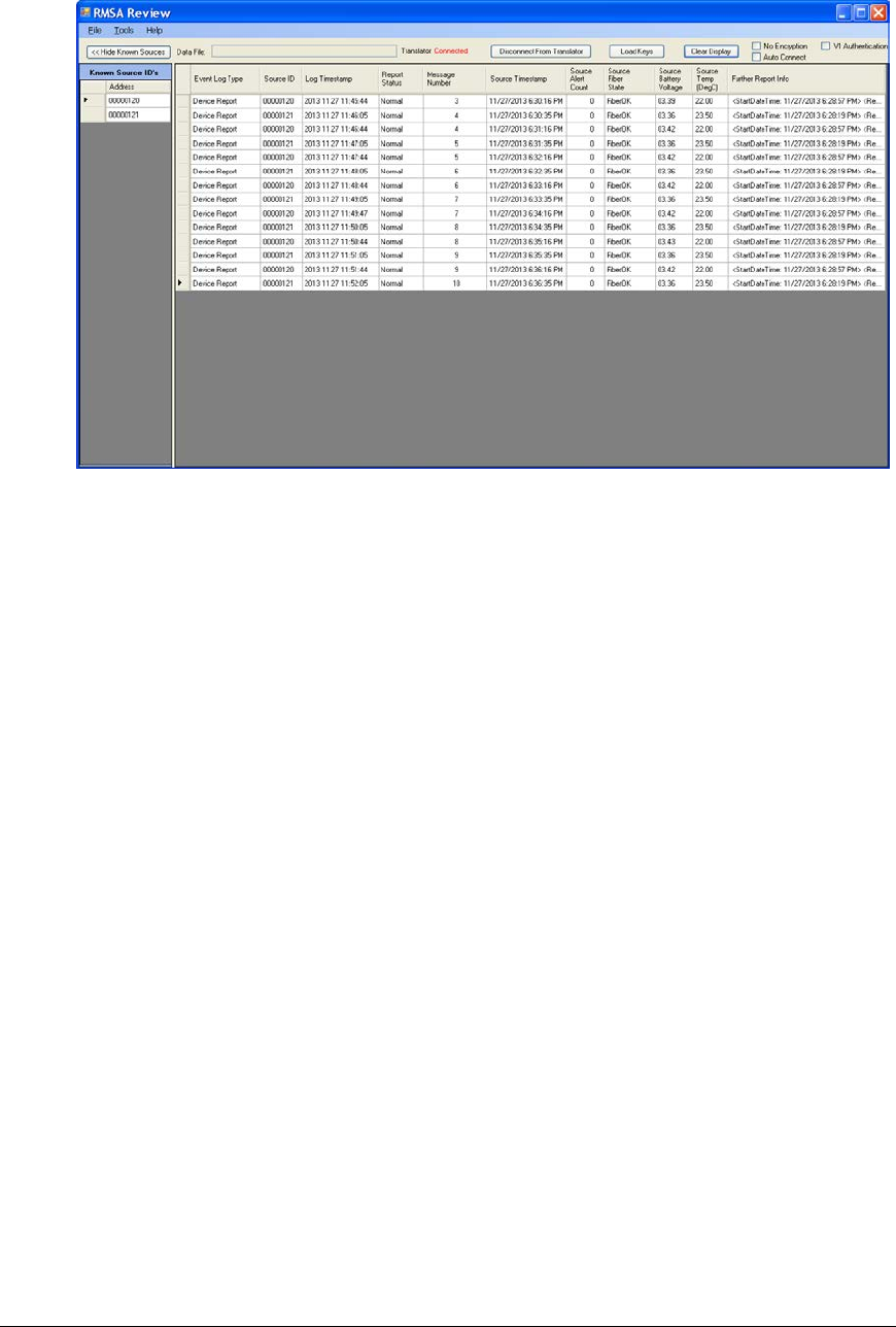
From the default view, note the following:
• Each row in the main display contains a Device Report row including a message
counter, the Source Timestamp column contains the UNIX encoded time field and the
Source Alert Count column contains the alert counter. These fields are included in
every State of Health Message. The source timestamp should mirror the seal
reporting period that was configured when programming the seal personality.
• The following Event Log Types may be included in the report:
o Device Report: a TLV message from a seal
o Translator Start: provides the timestamp of the start of the RMSA collection
application on the Translator.
o Cal Success: The Translator has detected conditions where the RF receiver
needed to be recalibrated and has successfully performed this task.
o Cal Failure: The Translator has detected conditions where the RF receiver
needed to be recalibrated and failed to successfully perform this task.
o Translator Tamper: Indicates a tamper event in the Translator enclosure.
• In Device Report entries, the following fields are reported with a standard SOH
message:
o The Source ID is the address of the reporting seal.
o The Log Timestamp is the time the seal report was logged by the Translator.
o The Report Status will indicate Normal, Alarm, Warning or Bad Key if the
message decryption fails. Alarm entries will be shaded red, Warning entries
are shaded yellow, normal messages are not shaded. In the example below,
REMOTELY MONITORED SEAL ARRAY(RMSA)
SFG-MAN-001
REVISION: 1.7
2016 CANBERRA
46
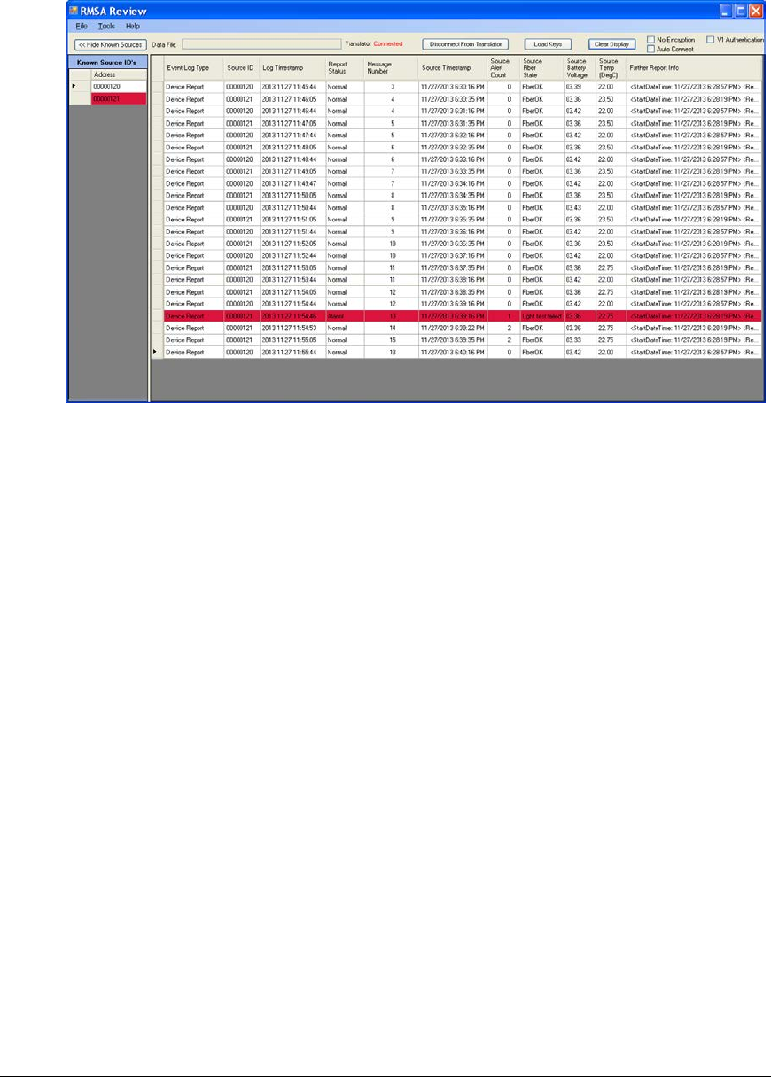
seal 00000121 reported an Alarm in the SOH message due to a failed light
test fiber status.
The seal logic includes a security feature that, under certain circumstances,
will delete the encryption and authentication keys configured during
personality programming and replace them with default keys. If the RMSA
Review GUI fails to decrypt and authenticate using the standard keys, it will
then try using the default keys. If the default key is required a “DK” code will
be added to the Report Status field. So a “Normal – DK” status indicates that
a normal SOH message has been received from the seal but a previous
event caused the keys to be replaced with default keys.
o The message number is the seals message count. The report should
contain consecutive message numbers for each seal. However, in a busy
situation where a number of seals are reporting at the same time, it is
possible that the SSP ACK/Retry logic will time out and the message will be
missed by the Translator. The message will be stored on the seal and can be
recovered with the SNDM command as described in section 5.4.
o The Source Alert Count contains a cumulative alert count for the seal. Note
in the figure above that the Source Alert Count for seal 45 changes from 0 to
1 when the fiber event is reported.
o Other standard SOH fields include the battery voltage, temperature and
tamper status of the seal at the time the SOH message was sent. The
Further Report Info would be empty under normal circumstances but may
contain additional TLV information in the case of an alert or warning.
• On the left side of the main display is a Known Device List. This list can be minimized
with the Hide Known Devices button if more screen space is desired for a custom
report view as described in section 5.3.3. The known device list can be used to create
seal-specific reports as described in section 5.3.2. Within the known device list, the
seal address is shaded by the highest noted alert level. I.e. if no problems have been
REMOTELY MONITORED SEAL ARRAY(RMSA)
SFG-MAN-001
REVISION: 1.7
2016 CANBERRA
47
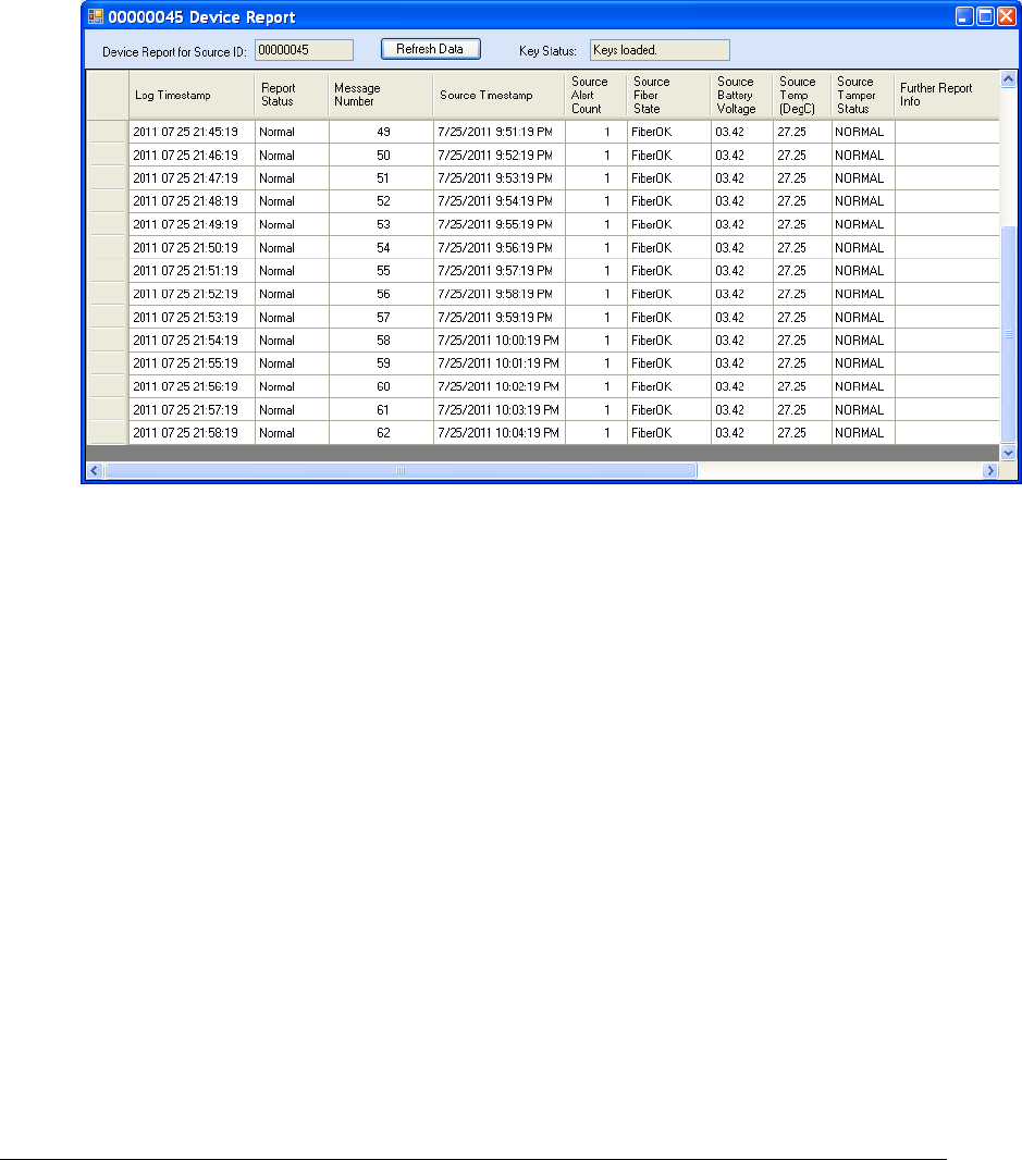
reported, the seal address is not shaded. If the seal has ever reported a warning, the
device address will be shaded red. If the seal has ever reported an alert, the address
is shaded red.
5.3.2 Device-Specific Report
Double click on the address cell of any seal in the Known Source ID’s list to get a pop-up report
containing only messages for that seal as illustrated below.
As with the main data display, it is possible to click on any column header to sort by that data.
Note that the device report is static – it is generated from the data available at the time it was
created. In Local Host mode, where data is continually being added to the main display, it may
be necessary to click the Refresh Data button to receive live updates.
With the Device-specific report, it is quite easy to note missing messages where the message
numbers are not consecutive. There may be valid reasons for a missing message. For
example, the ack/retry logic on the seal takes place in a relatively short amount of time to
conserve seal battery. If multiple seals are reporting at once, the Translator may not meet the
acknowledge time criteria for all seals and the message will not be received. However, the
message should still be available on the seal and can be resent with the Send Message data
request as described in section 5.4.
5.3.3 Customizing the Data View
Each Device Report log entry has more data available for forensics and detailed analysis than is
probably desired during the initial data review. The RMSA Review GUI provides a tool to allow
the operator to customize the data view. Under Tools, select Customize Report View. A window
similar to the following will be displayed:
REMOTELY MONITORED SEAL ARRAY(RMSA)
SFG-MAN-001
REVISION: 1.7
2016 CANBERRA
48
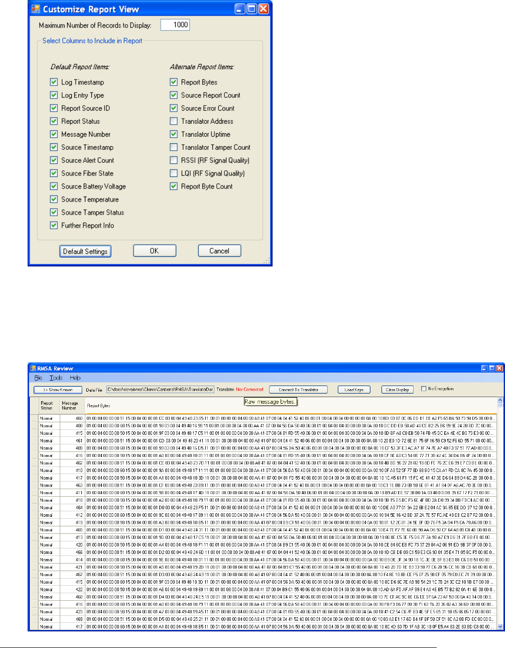
The items listed on the left are default report items and can be restored by pressing the Default
Settings button. Use the checkboxes for each of the default and alternate report items to select
the items to be visible then click OK. In the following example, the operator selected Report
Status, Message Number and Report Bytes. The Hide Known Sources button was clicked to
maximize the data view. The resulting display can be used to forensically examine message
bytes.
REMOTELY MONITORED SEAL ARRAY(RMSA)
SFG-MAN-001
REVISION: 1.7
2016 CANBERRA
49
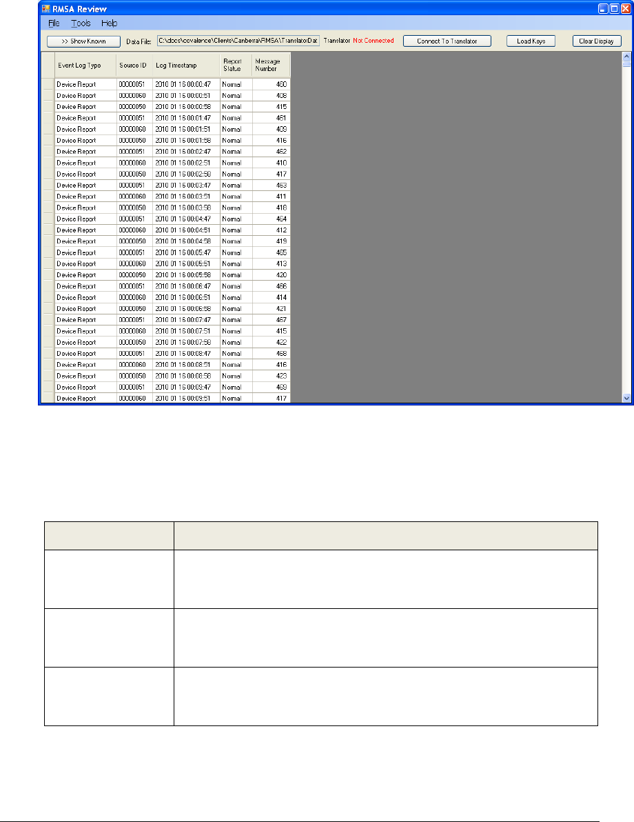
In the next example, the report view was customized to include only the Event Log Type, Source
ID, Log Timestamp, Report Status and Message Number. The resulting minimal display could
be used to quickly scan for Alarm or Warning conditions:
It is important to note that all data exists at all times within the GUI. Customizing the report view
only determines which data will be displayed. In other words, customizing the report view does
not cause the GUI to reload data from the translator.
The following table has a complete list of available Device Report data items:
Column Label Description of Contents
Event Log Type Describes the type of report – refer to section 5.3.1, above, for further
details. This column should always contain data and is included in the
default report view.
Source ID Contains the
seal address that originated a Device Report and is
empty for all other Event Log Types. This column is included in the
default report view.
Log Timestamp Contains the timestamp that the log entry was created on the translator
in the format MM/DD/YYYY hh.mm.ss. This column should always
contain data and is included in the default report view.
REMOTELY MONITORED SEAL ARRAY(RMSA)
SFG-MAN-001
REVISION: 1.7
2016 CANBERRA
50

Column Label Description of Contents
Report Status Some analysis of message data is performed by the GUI to categorize
each report as Normal, Warning or Alarm. Normal reports have no
background shading, Warning reports are shaded yellow and Alarm
reports are shaded red. In the case of a Normal report, the Report
Status is Normal. Warning or Alarm reports may have a Report Status
of Warning or Alarm or may further indicate the Warning or Alarm
source (such as “Bad key.”). This column should always contain data
and is included in the default report view.
Message Number Contains the seal message number for a Device Report in decimal
format. This column is included in the default report view.
Source Timestamp Contains the seal timestamp for a Device Report indicating the time
that the seal generated the report. This column is included in the
default report view.
Source Alert Count
Contains the seal’s cumulative alert count for a Device Report in
decimal format. This column is included in the default report view.
Source Fiber State Contains the seal’s fiber optic state for a Device Report. A fiber state
reading is interpreted by the seal into one of the following possible fiber
states:
• FiberOK
• Dark test failed
• Light test failed
• Measured light exceeds upper limit
• Measured light exceeds lower limit
• Positive threshold exceeds upper limit
• Negative threshold exceeds lower limit
• Measured light exceeds positive threshold
• Measured light exceeds negative threshold
• Unknown fiber state
A reported state of FiberOK is considered “Normal” all others are
considered an “Alarm”. This column is included in the default report
view.
Source Battery
Voltage Contains the seal’s battery voltage reading for a Device Report. This
column is included in the default report view.
Source Temp
Contains the seal’s temperature reading for a Device Report in
Degrees Celsius. This column is included in the default report view.
Source Tamper
Status Contains the seal’s tamper status reading for a Device Report. The
case tamper reading is analyzed by the seal and reported as either
Normal or Alarm. If “Alarm” is reported, the report is classified as an
Alarm report and shaded red. This column is included in the default
report view.
REMOTELY MONITORED SEAL ARRAY(RMSA)
SFG-MAN-001
REVISION: 1.7
2016 CANBERRA
51

Column Label Description of Contents
Further Report Info Contains information as necessary to support the log entry. In the
case of a Translator Tamper report, this column will contain further
information on the nature of the tamper. For Device Report log entries,
the column is used to report a Bad TLV or invalid TLV format. It may
also be used to report information from TLVs that are not normally
reported in a SOH message and do not, therefore, have a dedicated
column. This column is included in the default report view.
Report Bytes Contains a list of the raw report bytes (in hexadecimal) for a Device
Report. If the report bytes were successfully decrypted, the decrypted
report bytes are reported. Note that this column can be quite wide. To
examine the report bytes of a single entry, roll the mouse over the cell
for a 5-second pop-
up of the complete contents. Alternative,
customize the report view to remove other columns, then expand the
Report Bytes column width. Report bytes will typically not be of interest
for inspection outside of forensic investigations. Therefore, this column
is not included in the default report view. See Customizing Report
View, below for more information.
Source Report
Count The number of reports received by the translator from the seal source
address of this Device Report. This column is not included in the
default report view.
Source Error Count The number of errors logged by the translator for reports from the seal
source address of this Device Report. For example, RF payloads with
invalid SSP
header information are ignored (not processed and
logged), but a error counter is incremented. This column is not
included in the default report view.
Translator Address The translator address extracted from the SSP header for the Device
Report. In most cases, the Translator Address will be 0xff – unless the
translator device address has been modified during translator set-
up/configuration or corruption of the RF payload has occurred. This
column is not included in the default report view.
Translator Uptime The translator uptime (time since last boot) at the time the Device
Report was processed and logged. The uptime can be used as a
forensic indicator that the translator was unavailable for a period of
time. This column is not included in the default report view.
Translator Tamper
Count The cumulative count of translator case tampers at the time the Device
Report was processed and logged. This column is not included in the
default report view.
RSSI (RF Signal
Quality) The RSSI value is an indicator of RF signal quality and can be used
forensically by an RF expert to determine if there were problems with
the RF. This column is not included in the default report view.
LQI (RF Signal
Quality) The LQI value is an indicator of RF signal quality and can be used
forensically by an RF expert to determine if there were problems with
the RF. This column is not included in the default report view.
Report Byte Count The number of bytes included in a Device Report. The raw bytes are
viewable in the Report Bytes column. This column is not included in
the default report view.
REMOTELY MONITORED SEAL ARRAY(RMSA)
SFG-MAN-001
REVISION: 1.7
2016 CANBERRA
52
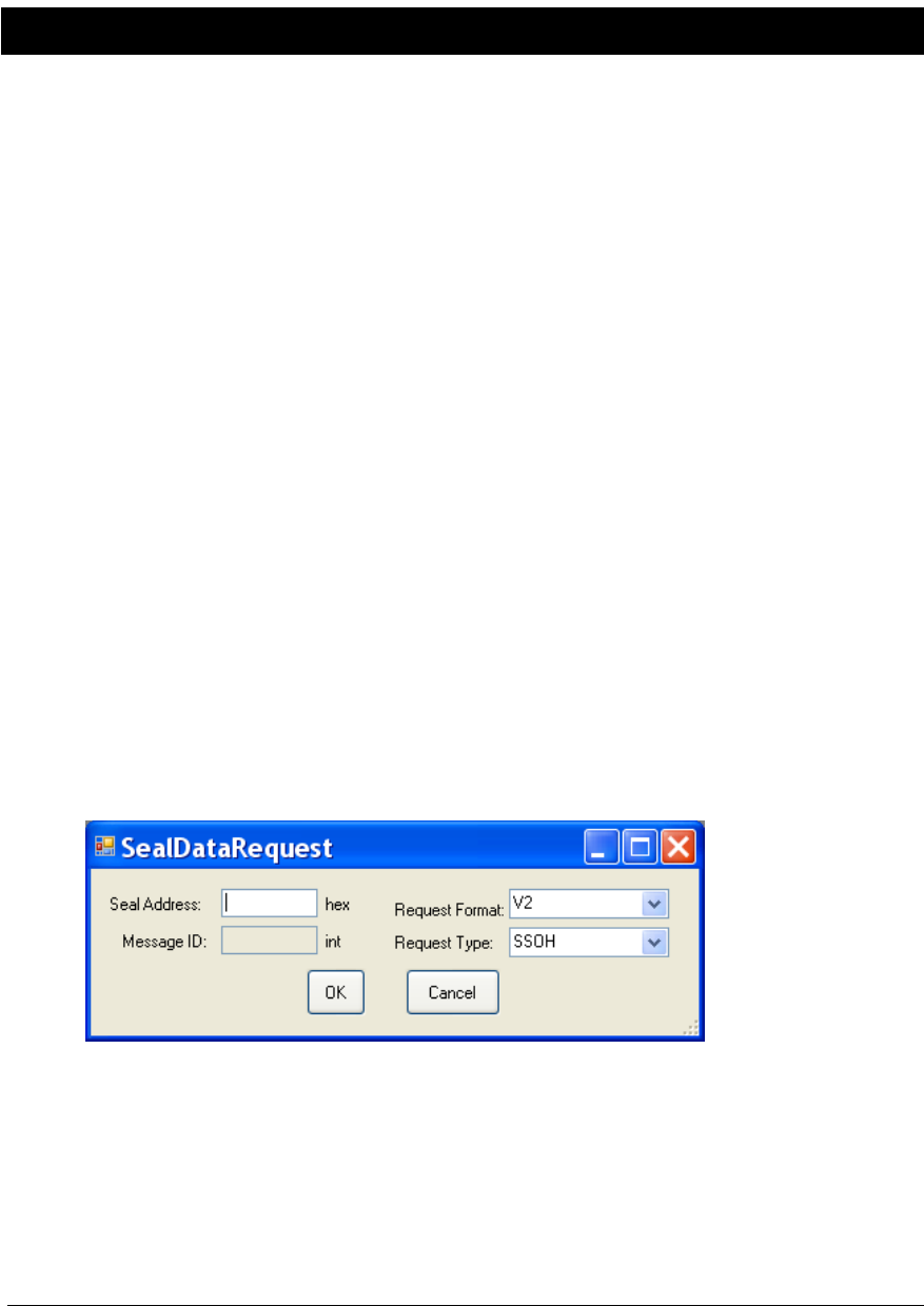
5.4 Requesting RMSA Seal Data
In Local Host Operation mode (refer to section 5.2.2) the RMSA Review GUI provides an
interface to request immediate data from the RMSA seals via Tools->Request Device Data.
Six types of data request are supported(refer to sections 5.4.1 thru 5.4.5).
Because the translator cannot access the contents of incoming TLV messages from seals
(due to encryption), the translator has no way of assigning a particular incoming message to a
particular request. A response message will be delivered to the GUI for evaluation of TLV
contents as with any autonomous SOH or alarm.
Further, seal response is not guaranteed. All commands sent to a seal require an
acknowledgement to the Translator. If the Translator does not detect an acknowledgement
within an adequate time period, the request will time out and the translator will retry up to 3
times. (Further data requests are locked out until the current data request completes, so a
finite number of attempts is necessary.) Data requests can be interrupted by autonomous
SOH or alarm messages from any seal resulting in a delayed acknowledge for the request.
Testing has shown that the translator’s three automatic retries are adequate in most cases, but
occasional misses still happen.
The GUI operator can watch the main display for the requested report from the seal address
specified in the request. If the report from the specified seal does not appear within 15
seconds, the GUI operator should repeat the request.
Procedures for each of the three requests are detailed below.
5.4.1 State of Health (SSOH) Request
To demand a SOH message from a seal, select Tools->Request Device Data. The following
pop-up will appear:
If necessary, click on the down arrow for the Request Type and select SSOH. (SSOH is the default
request type but the GUI will remember the last request type.) Enter the hexadecimal address of
the seal (from 1 to FFFFFFFF) in the Seal Address text box then press OK. Within 15 seconds, a
SOH report from the specified seal, using the next available message number, should appear in
the GUI’s main display.
REMOTELY MONITORED SEAL ARRAY(RMSA)
SFG-MAN-001
REVISION: 1.7
2016 CANBERRA
53

5.4.2 Extended State of Health (ESOH) Request
For an extended SOH request, enter the hexadecimal seal address (from 1 to FFFFFFFF) and
use the Request Type down arrow to select ESOH. The message ID text box is not activated as
a message number is not required for an ESOH request. Once the seal address has been
entered, click OK to continue. Click Cancel to abort the request.
Within 15 seconds, an extended SOH report from the specified seal, using the next available
message number, should appear in the GUI’s main display. The extended SOH report includes
entries in the Further Information column for the number of watchdog resets and the transmission
count for the seal.0
5.4.3 Send Message (SNDM) Request
To request a particular archived message, enter the hexadecimal seal address (from 1 to
FFFFFFFF) and use the Request Type down arrow to select SNDM. Once the SNDM request
type is selected, the Message ID text box is activated. Enter a valid message number for this
seal as a decimal value.
Message numbers start with 1. The maximum valid message number should be available in the
main display within the most recent autonomous State of Health message.
Click OK to send the request. Click Cancel to abort the request.
Within 15 seconds, the requested message number from the requested seal should appear
within the GUI window. Note that in default review mode, messages are sorted chronologically in
order of the log timestamp on the translator. Since the translator has no access to the TLV
contents of the message (due to encryption), it has no way of inserting the data in a day file log
based on the message number or time it was originally sent. Therefore, if interrogating a seal
that has been running for some time for message ID 1, the translator will log the event in the
current day file, not in the day file of the original transmission attempt. Similarly, the GUI will
present the new message (Message Number 1) at the end of the currently displayed data set.
5.4.4 Send Fiber History (HIST) Request
To request a history of all fiber optic event messages generated (up to a limit of ~383), enter the
hexadecimal seal address (from 1 to FFFFFFF) and use the Request Type down arrow to select
HIST. Once the seal address has been entered, click OK to continue. Click Cancel to abort the
request.
Within 15 seconds, a list of the seal’s fiber optic event messages should appear in the GUI’s
main display.
5.4.5 Send RMSA To Translator Associate(RTTA) and RMSA To Translator
Disassociate(RTTD) Request
The RMSA To Translator Associate (RTTA) and Disassociate (RTTD) commands were created
for seals that do not provide translator addresses during personality programming. The address
of the Translator that is connected to the GUI will be used by the seal after successfully sending
this message. Before receiving the RTTA command, the seal will buffer but not transmit
messages. Upon receiving RTTA command, the seal will check a list of all messages buffered
and send those to the associated translator all at once. Upon receiving the RTTD command, the
REMOTELY MONITORED SEAL ARRAY(RMSA)
SFG-MAN-001
REVISION: 1.7
2016 CANBERRA
54

seal will once again no longer transmit, but buffer messages in flash memory. Messages will
continue being buffered until a new RTTA command is received. Note that these commands
only work when translator addresses are not downloaded during personality programming.
The message number is not required for a RTTA or RTTD command. Enter the hexadecimal
seal address (from 1 to FFFFFFFF) then click OK to continue or Cancel to abort the request.
Within 15 seconds, buffered messages should begin to appear in the GUI’s main display.
REMOTELY MONITORED SEAL ARRAY(RMSA)
SFG-MAN-001
REVISION: 1.7
2016 CANBERRA
55

This page left blank intentionally
REMOTELY MONITORED SEAL ARRAY(RMSA)
SFG-MAN-001
REVISION: 1.7
2016 CANBERRA
56