CANBERRA RS-915 GPS-COM SUPERVISOR/REPEATER User Manual
CANBERRA GPS-COM SUPERVISOR/REPEATER
CANBERRA >
Contents
- 1. Users Manual
- 2. Users Manual II
- 3. Users Manual III
Users Manual

Type Emetteur Code Article Indice Format Page
DEX 040 86378 A 4 0
Des informations confidentielles sont contenues dans ce document. Toute reproduction doit être soumise à l'accord de CANBERRA.
Confidential information are included in this document. Copy of this document is submitted to CANBERRA acceptance.
Référence informatique : \\Svr-dc1-2k3\Data\4. CEM\4-1. Dossier CEM\4-1-1. Encours\027\027115\Documents\86378_A.doc
Canberra France FAB F 026 VB
Titre / Title : User manual GPS-COM (spécial USA)
HISTORIQUE DES MODIFICATIONS / MODIFICATIONS CHRONOLOGY
Ind.
Rev. Date
Date Origine des modifications
Modifications origin Paragraphes concernés
Related sections
A 04/04/08 Première édition / First edition d’après gpscom manual-2
(Meriden)
Manuel utilisateur / User's manual
Ind. Rédigé par / Written by Vérifié par / Verified by Approuvé par / Approved by
Date / Date 03/04/2008 Date / Date 03/04/2008 Date / Date 03/04/2008
Nom / Name C. DESBARATS Nom / Name P. BLOT Nom / Name
A
Visa / Visa Visa / Visa Visa / Visa

USER MANUAL
GPS-COM &
SUPERVISOR/REPEATER
GPS-COM /868 MHz code 83435
GPS-COM /915 MHz code 83436
Sup/Rep 868 MHz code 86288
Sup/Rep 915 MHz code 86289

USER MANUAL
GPS-COM
code 83435 & 83436
Supervisor/Repeater
code 86288 & 86289
April 2008

USER MANUAL
GPS-COM
86378_A
3 / 32 CANBERRA Industries
800 Research Parkway
MERIDEN, CT 06450
WARNING
CANBERRA cannot be held responsible for any damage incurred by the buyer due to faulty use,
connection to the wrong voltage, or non-observance of the instructions found in this manual.
The information contained herein may be altered without notice.
Any full or partial reproduction of this document may only be made after obtaining prior permission
from CANBERRA.

USER MANUAL
GPS-COM
CANBERRA Industries
800 Research Parkway
MERIDEN, CT 06450
4 / 28
86378_A
TABLE OF CONTENTS
1. SYSTEM FUNCTIONAL DESCRIPTION ................................................................................................7
2. HARDWARE FEATURES........................................................................................................................8
2.1. GPS-COM MODULE...........................................................................................................................8
2.2. SUPERVISOR/REPEATER MODULE .......................................................................................................9
3. HARDWARE OPERATION....................................................................................................................10
3.1. GPS-COM MODULE.........................................................................................................................10
3.1.1. Normal Power On/Off Sequence ....................................................................................10
3.1.2. 3.1.2. Enabling the Program Mode.................................................................................11
3.1.3. 3.1.3. Charging the Battery .............................................................................................11
3.2. SUPERVISOR/REPEATER MODULE .....................................................................................................12
3.2.1. Normal Power On/Off Sequence ....................................................................................12
3.2.2. 3.2.2. Enabling the Program Mode.................................................................................13
3.2.3. Charging the Battery .......................................................................................................13
3.2.4. Notes on Communication Operations ...........................................................................13
4. STARTING & CONFIGURING THE GPSCOM SYSTEM......................................................................14
5. SYSTEM OPERATION: VIEWING GPSCOM & URAD STATUS.........................................................16
6. SYSTEM OPERATION: MAP & DATA VIEWS.....................................................................................17
6.1. 6.1. MAP VIEW .................................................................................................................................17
6.2. DATA VIEW.......................................................................................................................................18
7. SYSTEM OPERATION: DYNAMIC GPSCOM DEVICE CONNECTIONS............................................19
7.1. CONNECTING GPS-COM DEVICES....................................................................................................19
7.2. 7.2. DISCONNECTING GPSCOM DEVICES .........................................................................................20
8. SYSTEM OPERATION: DYNAMIC SUPERVISOR/REPEATER MODULE CONNECTIONS .............20
8.1. INSTALLING OR REMOVING REPEATER MODULES ...............................................................................20
8.2. REMOVAL OF A REPEATER-PC OR SECONDARY-REPEATER MODULE .................................................21
8.2.1. Insertion of a Repeater-PC or Secondary-Repeater Module.......................................21
8.3. INSTALLING OR REMOVING SUPERVISOR MODULES ............................................................................21
8.3.1. Removal of a Supervisor-PC or Supervisor Module....................................................21
8.3.2. Insertion of a Supervisor-PC or Supervisor Module....................................................22
9. POWERING OFF THE SYSTEM ...........................................................................................................22
10. MAINTENANCE & SERVICE INFORMATION......................................................................................22
10.1. INTERNAL LITHIUM-ION BATTERIES .......................................................................................22
10.2. REPLACEMENT COMPONENTS ..............................................................................................23
11. DECLARATION OF CONFORMITY......................................................................................................23
11.1. EUROPE ..............................................................................................................................23
11.2. US – FCC...........................................................................................................................23
12. SPECIFICATIONS .................................................................................................................................24
12.1. GPSCOM HANDHELD DEVICE .............................................................................................24
12.2. SUPERVISOR/REPEATER MODULE ........................................................................................26
USER MANUAL
GPS-COM
86378_A
5 / 32 CANBERRA Industries
800 Research Parkway
MERIDEN, CT 06450
GPS-COM + UltraRadiac Supervisor/repeater
USER MANUAL
GPS-COM
86378_A
7 / 32 CANBERRA Industries
800 Research Parkway
MERIDEN, CT 06450
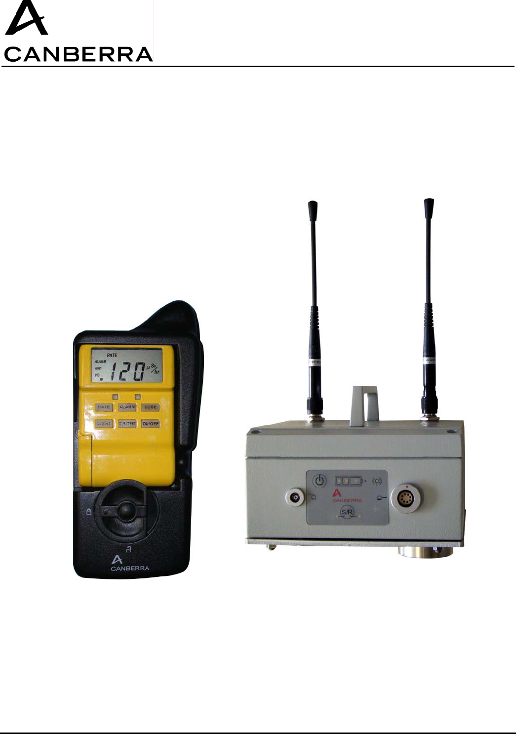
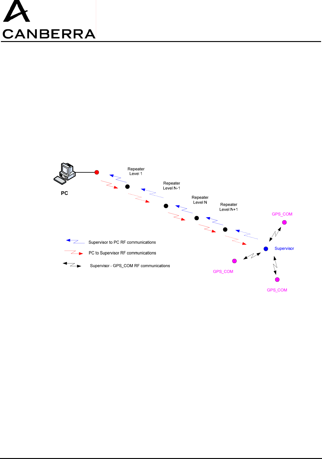
1. SYSTEM FUNCTIONAL DESCRIPTION
The GPSCOM system allows the UltraRadiac to communication wirelessly through a 915MHz (US) or
868MHz (EU) RF transceiver, sending both radiological and GPS position data. A standard GPSCOM
system includes a set of GPSCOM-equipped URAD devices, up to 200 devices maximum per system,
and one or more Supervisor/Repeater modules. The Supervisor/Repeater modules relay information
between the host computer and the GPSCOM devices deployed in the field. To extend the
communication range of the system, additional Repeater modules may be inserted between the
computer and Supervisor module.
Repeater-PC
USER MANUAL
GPS-COM
CANBERRA Industries
800 Research Parkway
MERIDEN, CT 06450
8 / 28
86378_A
2. HARDWARE FEATURES
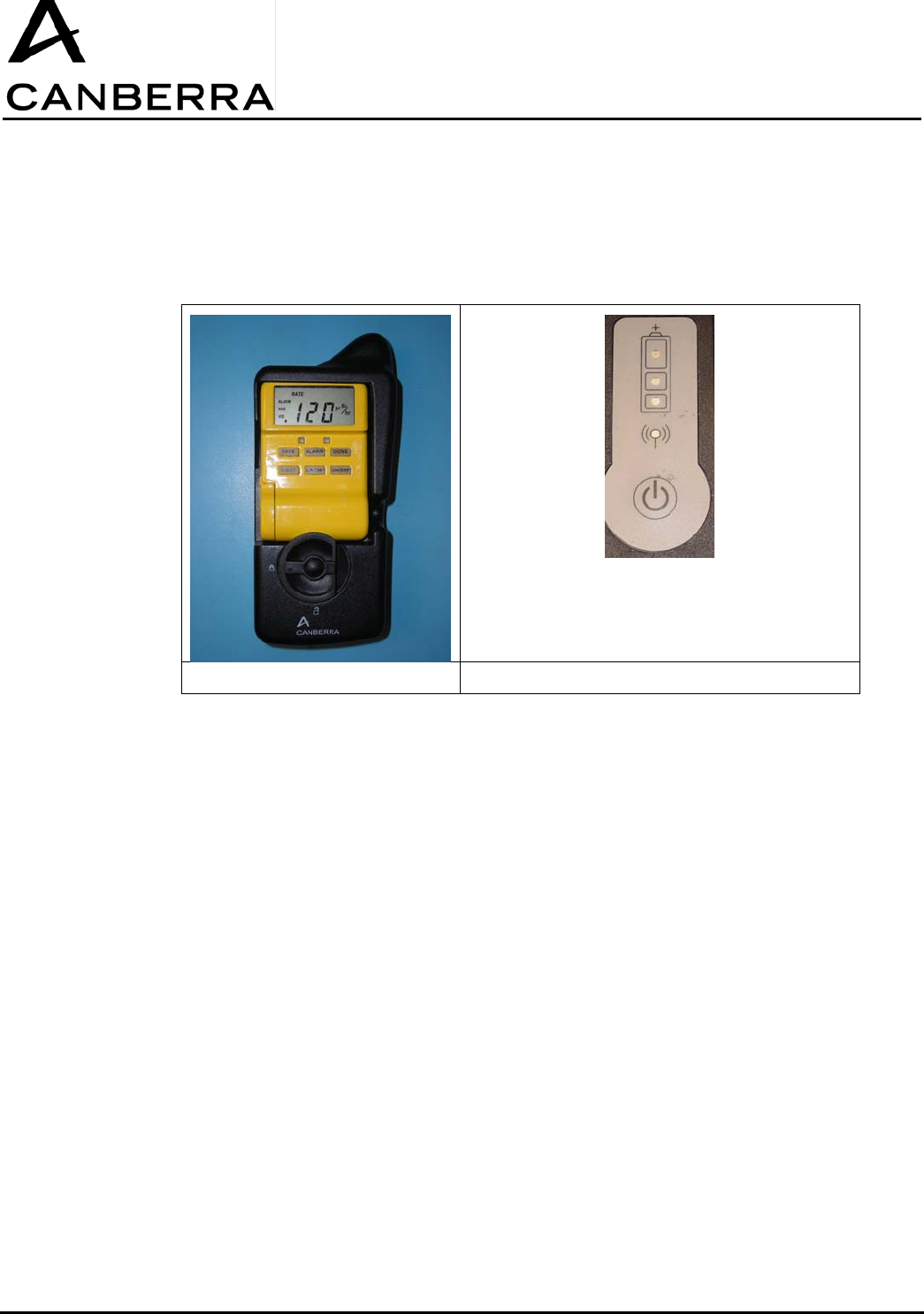
2.1. GPS-COM MODULE
This section describes the basic hardware features and functions of the GPS-COM handheld device.
GPSCOM Control
Locking Mechanism:
The locking mechanism rotates to secure the URAD into position in the GPSCOM.
IrDA Communication Port:
The GPSCOM communicates with the URAD through the infrared transceiver located behind this
window.
External Power Connector:
This connector accepts external power from the supplied 5V-2A AC/DC adapter to charge the
GPSCOM internal battery.
Power Button:
Pressing and holding the power button momentarily will switch the GPSCOM on or off alternately, and
only when the external power adapter is not connected.
Green, Orange, and Red ”Battery” Status LEDs:
When the GPSCOM is in operation and is not connected to its external power adapter, the appropriate
colored LED will blink to indicate the remaining capacity of the internal battery. When the GPSCOM is
connected to its external power adapter, the appropriate colored LED will turn on steady to indicate the
battery charging status.
USER MANUAL
GPS-COM
86378_A
9 / 32 CANBERRA Industries
800 Research Parkway
MERIDEN, CT 06450
Blue “Link” Status LED:
The Blue status LED indicates when the RF communication link with the Supervisor is active.
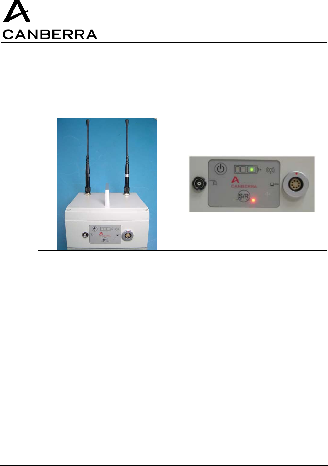
2.2. SUPERVISOR/REPEATER MODULE
This section describes the basic hardware features and functions of the Supervisor/Repeater module.
Supervisor/Repeater Control Panel
Tripod Mount:
The threaded insert on the base of the Supervisor/Repeater module allows for mounting the module on
an optional tripod.
Magnetic Feet:
The three feet on the base of the module allow it to be magnetically mounted to most common steel or
other ferromagnetic structures.
Data connector:
The data connector is a serial interface, which communicates with the host computer through the
supplied Serial-to-USB data cable.
External Power Connector:
This connector accepts external power from the supplied 5V-5A AC/DC adapter to charge the internal
battery.

USER MANUAL
GPS-COM
CANBERRA Industries
800 Research Parkway
MERIDEN, CT 06450
10 / 28
86378_A
Power Button:
Pressing and holding the power button momentarily will switch the Supervisor/Repeater module on or
off alternately.
“S/R” Button:
Pressing and holding the power button momentarily will switch the Supervisor/Repeater module
operating mode between Supervisor or Repeater.
Red “S/R” Status LEDs:
A corresponding Red status LED adjacent to the “S/R” button will turn on to indicate the module
operating mode as either a Supervisor or a Repeater.
Green, Orange, and Red ”Battery” Status LEDs:
When the Supervisor/Repeater is in operation and is not connected to its external power adapter, the
appropriate colored LED will blink to indicate the remaining capacity of the internal battery. When the
GPSCOM is connected to its external power adapter, the appropriate colored LED will turn on steady to
indicate the battery charging status.
Blue “Link” Status LED:
The Blue status LED indicates when the Supervisor/Repeater module has been successfully connected
to the GPSCOM network, either by direct connection to the host computer or through RF link to another
S/R module.
3. HARDWARE OPERATION
3.1. GPS-COM MODULE
3.1.1. Normal Power On/Off Sequence
The following procedure outlines the normal operating sequence of the GPSCOM with a URAD
installed.
1) First, install and power on the URAD by pressing and briefly holding its ON/OFF button until its display
activates.
2) Switch on the GPSCOM by pressing and briefly holding down the power button until all four status
LEDs turn on.
3) Immediately after applying power, the GPSCOM will attempt to establish communication with the
URAD. During this time, the status LEDs of the GPSCOM will follow the sequence below:
a) Green LED turns off briefly to indicate that GPSCOM is initializing communication with URAD.
b) Green LED turns back on to indicate that URAD has responded and the IR communication link is
active. (Note that all four LEDs may remain on momentarily while initialization continues.)
c) All four status LEDs then turn off briefly.

USER MANUAL
GPS-COM
86378_A
11 / 32 CANBERRA Industries
800 Research Parkway
MERIDEN, CT 06450
4) The GPSCOM will now indicate its remaining battery capacity by flashing the appropriate color status
LED as follows:
Green: greater than 33% capacity
Orange: less than 33% capacity
Red: less than 10% capacity
5) If an RF Supervisor is in operation, the GPSCOM will then automatically attempt to connect to it. Once
the connection is established, the Blue status LED will turn on and remain steady. If no RF Supervisor
is available, the Blue status LED will not turn on.
6) To switch off the GPSCOM, press and briefly hold the power button again until all four status LEDs
turn on. After releasing the button, all four LEDS will be off and the GPSCOM will be powered off.
3.1.2. 3.1.2. Enabling the Program Mode
The following procedure outlines the steps necessary to change the internal firmware of the GPSCOM
with no URAD installed.
1) Switch on the GPSCOM by pressing and briefly holding the power button until all four status LEDs turn
on.
2) Immediately after applying power, the GPSCOM will attempt to communicate with the URAD, and only
the Green status LED will turn off.
3) The Green status LED will remain off for approximately one minute, then all four status LEDs will turn
off briefly. (Note that pressing and holding the power button for approximately 5 seconds during this
one minute interval will cause a Reset of the GPSCOM, which will be indicated by a rapidly flashing
Green status LED. Pressing the power button again until all four LEDs turn on will resume the
communication link process. It is not possible to switch off the GPSCOM during either of these
operating modes.)
4) The GPSCOM will now indicate its remaining battery capacity by flashing the appropriate color status
LED as follows:
Green: greater than 33% capacity
Orange: less than 33% capacity
Red: less than 10% capacity
5) The GPSCOM will now be in Program mode, allowing its firmware to be changed by a computer
communicating with the GPSCOM through its IrDA data port.
6) When the firmware update is completed, switch off the GPSCOM by pressing and briefly holding the
power button again until all four status LEDs turn on. After releasing the button, all four LEDS will be
off and the GPSCOM will be powered off.
3.1.3. 3.1.3. Charging the Battery
The following procedure outlines the steps to charge the GPSCOM internal battery. Note that it is not
possible to operate any of the GPSCOM functions while the external power adapter is connected.
However, it is possible to interrupt the charging process at any time by disconnecting the external
power adapter, and no damage to the internal battery will result.
7) Connect the supplied AC/DC power adapter to the GPSCOM, and connect the adapter to a 100-240V
50/60Hz outlet using the appropriate plug.

USER MANUAL
GPS-COM
CANBERRA Industries
800 Research Parkway
MERIDEN, CT 06450
12 / 28
86378_A
8) The GPSCOM will automatically begin charging its internal battery, and will indicate the charge status
by turning on the appropriate color LED as follows:
Green = 100% capacity (charge complete)
Orange = less than 99% capacity
Red = less than 10% capacity
9) When charging is complete, the Green LED will turn on and the external power adapter may be
disconnected.
3.2. SUPERVISOR/REPEATER MODULE
3.2.1. Normal Power On/Off Sequence
The following procedure outlines the normal operating sequence of the Supervisor/Repeater module.
1) For a Supervisor-PC or Repeater-PC, connect the Supervisor/Repeater module to the host computer
USB port using the supplied data communication cable. Note that a Secondary-Repeater or Supervisor
is operated as a standalone module, and would not be connected to a PC.
2) Switch on the Supervisor/Repeater module by pressing and briefly holding the power button until all
four status LEDs turn on.
3) If external power is connected to the module, the Blue status LED will turn on briefly and the
Supervisor/Repeater module will indicate its charging status by turning on the appropriate color LED as
follows:
4) Green = 100% capacity (charge complete)
Orange = less than 99% capacity
Red = less than 10% capacity
If no external power is connected, all “Battery” and “Link” status LEDs will turn on briefly, followed by
the battery level indicated by a blinking status LED as follows:
Green: greater than 33% capacity
Orange: less than 33% capacity
Red: less than 10% capacity
5) The Supervisor/Repeater module will now also indicate its operating mode before it was last switched
off, by turning on the corresponding Red “S” or “R” status LED next to the “S/R” button.
6) To change the mode between Supervisor or Repeater operation, press and momentarily hold the “S/R”
button. All “Battery” and “Link” status LEDs will turn on briefly, then the status LEDs will indicate the
battery level or charging status along with the new operating mode. (Note that when external power is
connected, changing the S/R mode will also reset the module back to Charge mode and it will be
necessary to switch power on again. When switched back on, the S/R module will be in the newly
selected operating mode.)
7) The Blue status LED will only turn on after a “Start Network” command has been issued by the host
computer and the S/R module has been successfully linked to the network, either by direct connection
to the host computer or through RF link to another S/R module.
8) To switch off the S/R module, press and briefly hold the power button again until all four “Battery” and
“Link” status LEDs turn on. After releasing the button, all status LEDS will be off and the S/R will be
powered off.

USER MANUAL
GPS-COM
86378_A
13 / 32 CANBERRA Industries
800 Research Parkway
MERIDEN, CT 06450
9) If the external power adapter is connected, the S/R module will automatically enter Charge mode and
the charging status will be indicated by a Red, Orange, or Green status LED according to the battery
capacity as described in step 3 above.
3.2.2. 3.2.2. Enabling the Program Mode
The following procedure outlines the steps necessary to change the internal firmware of the
Supervisor/Repeater module.
1) Connect the S/R module to the host computer USB port using the supplied data communication cable.
2) Switch on the S/R by pressing and briefly holding the power button until all four “Battery” and “Link”
status LEDs turn on.
3) Press and hold the power button again until the Green status LED blinks rapidly, and the Red “S” or
“R” status LED turns off. This indicates that the S/R is now ready to receive a firmware change through
the computer connected to the serial data connector.
4) When programming is completed, press and briefly hold the power button again until all four “Battery”
and “Link” status LEDs turn on. The S/R module will now return to its normal operating mode, and the
status LEDs will indicate the battery level or charging status along with the present operating mode.
5) To switch off the S/R module, press and briefly hold the power button again until all four “Battery” and
“Link” status LEDs turn on. After releasing the button, all status LEDS will be off and the S/R module
will be powered off.
3.2.3. Charging the Battery
The following procedure outlines the steps to charge the S/R internal battery. Note that it is possible to
interrupt the charging process at any time by disconnecting the external power adapter, and no damage
to the internal battery will result.
1) Connect the supplied AC/DC power adapter to the S/R, and connect the adapter to a 100-240V
50/60Hz outlet using the appropriate plug.
2) The S/R will automatically begin charging its internal battery, and will indicate the charge status with
the appropriate color LED as follows:
Green = 100% capacity (charge complete)
Orange = less than 99% capacity
Red = less than 10% capacity
3) When charging is complete, the Green LED will turn on and the external power adapter may be
disconnected.
3.2.4. Notes on Communication Operations
Supervisor must not be turned off once communicating with GPSCOMs, otherwise entire network must
be restarted.
Blue status LED must remain on at all times – if LED turns off, indicates communication fault.
If software is closed, Supervisor will continue to communicate with GPSCOM – it is not required to re-
scan and re-start network.
Connection or disconnection of data cable will force reset of S/R microcontroller.
USER MANUAL
GPS-COM
CANBERRA Industries
800 Research Parkway
MERIDEN, CT 06450
14 / 28
86378_A
4. STARTING & CONFIGURING THE GPSCOM SYSTEM
1) Refer to sections 3.1.1 and 3.2.1 above to connect and activate all Supervisor/Repeater and GPSCOM
modules in the network, and select the appropriate operating mode for each S/R module.
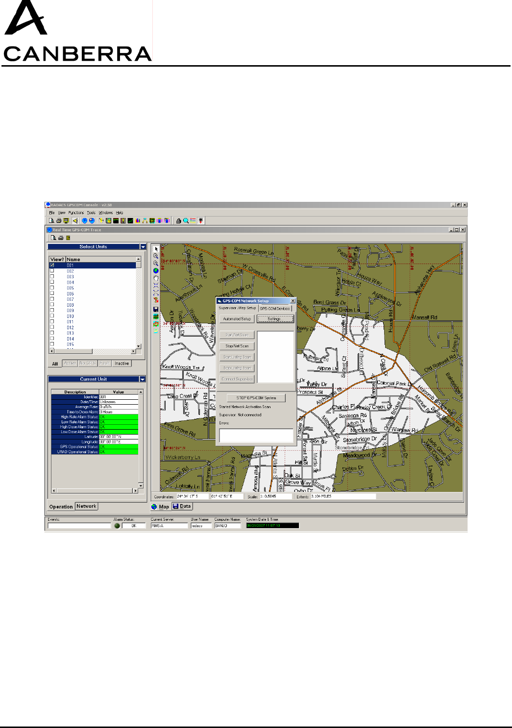
2) Open the RADACS software on the host computer. The RADACS Server window will open, followed
by the RADACS GPSCOM Console window. The GPSCOM Network Wizard window will then open
automatically to begin the network initialization process:
3) Click the “Start Net Scan” button in the GPSCOM Network Setup dialog box. After a moment, the Blue
“Link” status LED on each Supervisor/Repeater module will turn on steady to indicate successful
communication link to the network.
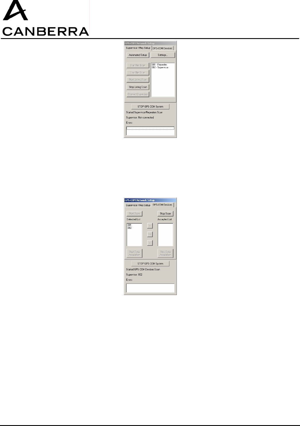
4) Next, click the “Stop Net Scan” button in the GPSCOM Network Setup dialog box, followed by the
“Start Listing Scan” button. After a moment, the dialog box will list all of the detected
Supervisor/Repeater modules along with their corresponding operating modes.
5) When the scan is complete, click the “Stop Listing Scan” button, followed by the “Connect Supervisor”
button in the dialog box.
USER MANUAL
GPS-COM
86378_A
15 / 32 CANBERRA Industries
800 Research Parkway
MERIDEN, CT 06450
6) Once the Supervisor has successfully responded to the server, the Network Setup Wizard will
automatically transition to the GPSCOM Devices tab. However if the Supervisor fails to respond, an
error message will be displayed in the lower portion of the Network Setup dialog box.
7) In the GPSCOM Devices tab of the Network Setup dialog box, click the “Start Scan” button. After a few
moments, the scan will progress and active GPSCOM modules will be displayed in the “Detected List”:
8) When the scan is complete, click the “Stop Scan” button in the dialog box. GPSCOM units may now be
added to the “Accepted List” on the righthand side to accept them into the network. This is done either
by selecting units individually and clicking the “>” button or by selected all units with the “>>” button in
the dialog box. If a GPSCOM unit fails to join the network properly, an error message will be displayed
in the lower portion of the Network Setup dialog box, and the unit will remain in the Detected List.
9) When all of the applicable GPSCOM units have been accepted into the network, click the “Start Data
Acquisition” button in the Network Setup dialog box. This will initiate data transfer between the
GPSCOM units and the Supervisor.
10) Upon successful initiation of the Data Acquisition mode, the Network Setup Wizard will close and
operation will return to the RADACS GPSCOM Console window.
11) The Network Setup Wizard may be manually reopened at any time by clicking on the “Network” tab at
the lower lefthand side of the RADACS GPSCOM Console window. The Network tab will be displayed

USER MANUAL
GPS-COM
CANBERRA Industries
800 Research Parkway
MERIDEN, CT 06450
16 / 28
86378_A
automatically if there is any change in the GPSCOM network status, including a newly detected
GPSCOM unit or communication error between the computer and the Supervisor.
12) To stop the data acquisition process at any time, click the “Stop Data Acquisition” button in Network
Setup. To stop the entire GPSCOM network at any time, click the “Stop GPSCOM System” button in
Network Setup. Note that if the GPSCOM network is stopped, the Network Setup Wizard will default
back to the “Supervisor/Repeater Setup” tab and the entire setup procedure beginning at Step 3 above
must be repeated to restart the network again.
5. SYSTEM OPERATION: VIEWING GPSCOM & URAD STATUS
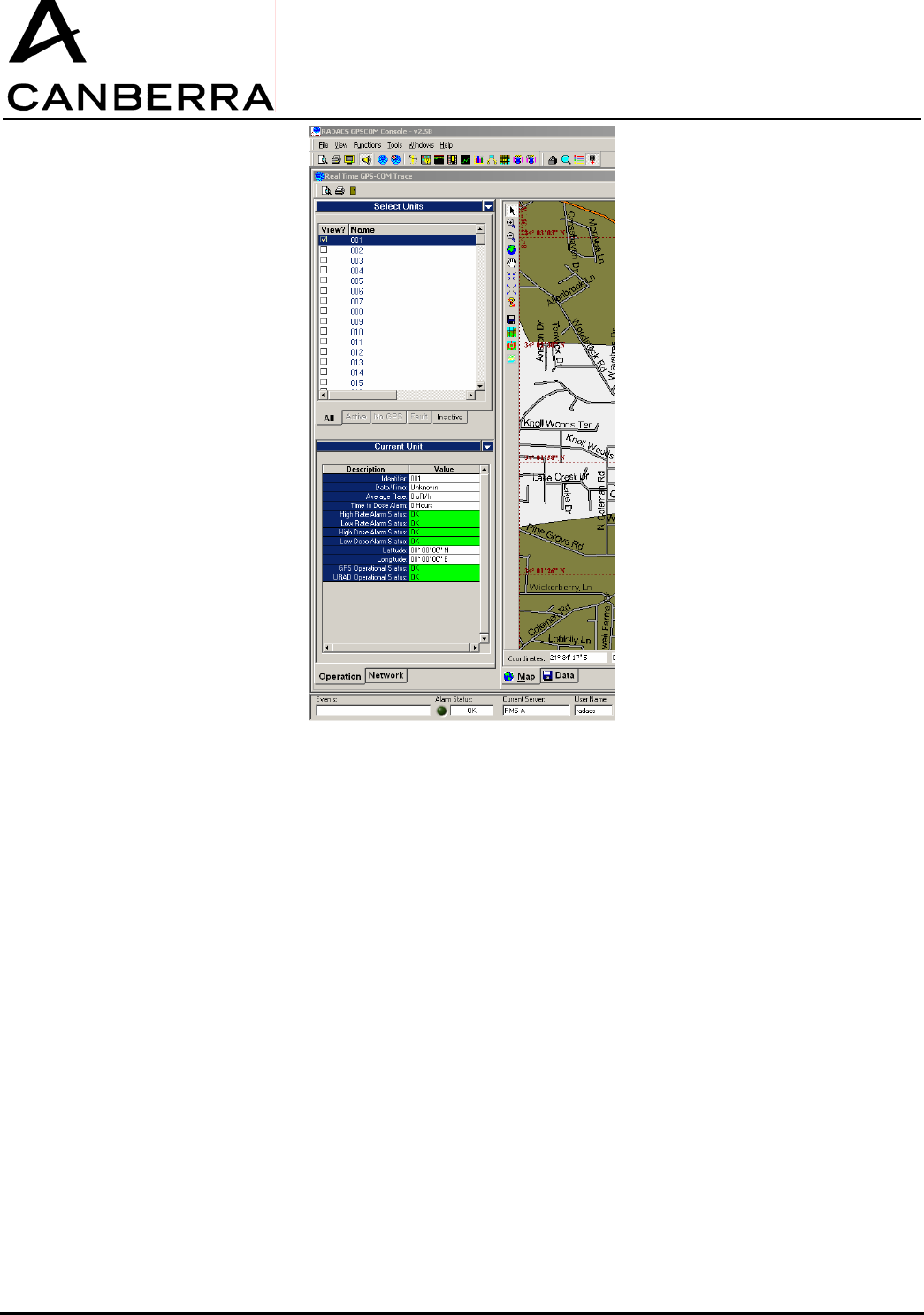
1) Start the “Real-Time GPSCOM Trace” function, located in the RADACS GPSCOM Console
“Functions” menu. Be sure that the “Start Data Acquisition” button in the Network Setup Wizard has
also been selected to initiate data transfer between the GPSCOM units and the Supervisor.
2) The “Select Units” window on the lefthand side of the main console will display a list of GPSCOM units
in the network. The units listed will vary depending on their operational status and the corresponding
tab selected along the bottom edge of the Selected Units window:
All: all units defined in the network, regardless of operating status
Active: units supplying both measurement and GPS position data
No GPS: units supplying measurement data, but no valid GPS position data
Fault: units supplying GPS position data, but no measurement data (i.e. URAD off)
Inactive: units not supplying any measurement or GPS data (i.e. GPSCOM off or out of range)
3) Click on a unit to highlight it in the Select Units list. The “Current Unit” window immediately below will
display more detailed information about the status of the selected URAD and GPSCOM device
including measurements, GPS position and time data, as well as any fault or alarm conditions that may
exist.
USER MANUAL
GPS-COM
86378_A
17 / 32 CANBERRA Industries
800 Research Parkway
MERIDEN, CT 06450
6. SYSTEM OPERATION: MAP & DATA VIEWS
The two primary methods for displaying GPSCOM system status in the RADACS GPSCOM Console
are the Map and Data views provided through the Real-Time GPSCOM Trace function. The following
sections describe the operation of these two information displays.
6.1. 6.1. MAP VIEW
1) If it is not already running, start the “Real-Time GPSCOM Trace” function, which is accessed through
the RADACS GPSCOM Console “Functions” menu. Be sure that the “Start Data Acquisition” button in
the Network Setup Wizard has also been selected to initiate data transfer between the GPSCOM units
and the Supervisor.
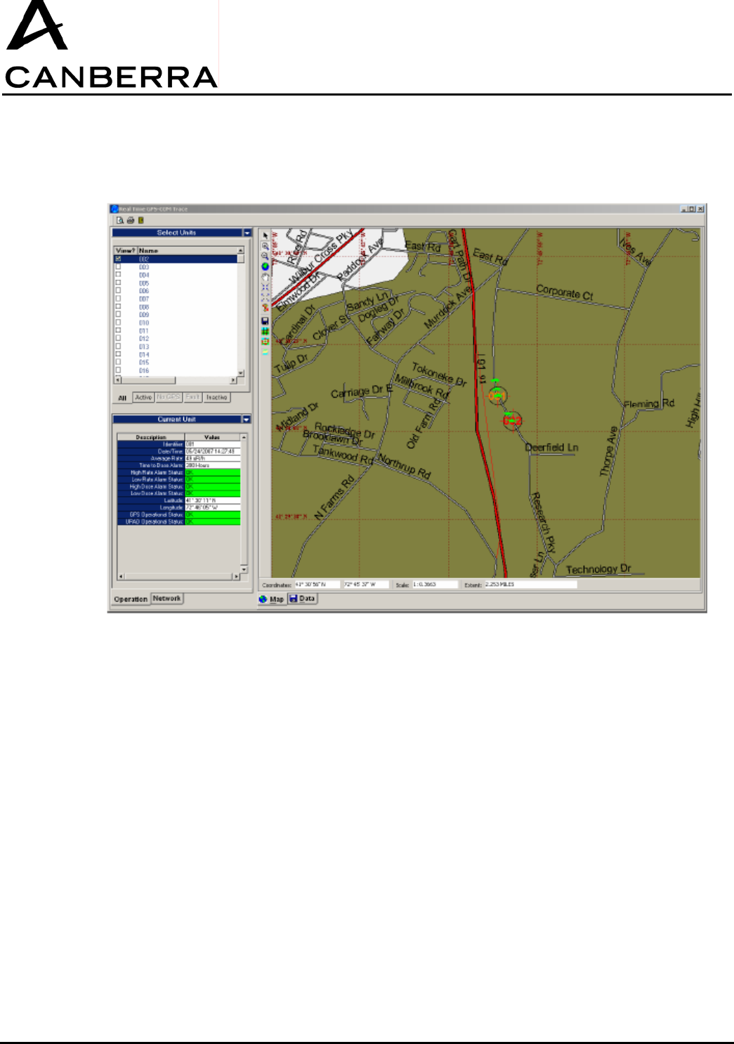
2) The main portion of the Real-Time GPSCOM Trace window will display the Map View, which is also
available by clicking on the “Map” tab along the lower edge.
3) Click the “Active” tab along the lower edge of the “Select Units” window on the lefthand side. To view a
specific unit on the map, click the checkbox to the left of this unit’s name in the “Select Units” listing.
4) An icon containing the name of each unit will be displayed on the map, indicating the GPS position of
all units selected for view in the “Select Units” list. The color of each icon represents the radiological
alarm status of the corresponding URAD unit as follows:
Green: No Alarm
Yellow: Low Rate Alarm
USER MANUAL
GPS-COM
CANBERRA Industries
800 Research Parkway
MERIDEN, CT 06450
18 / 28
86378_A
Red: High Rate Alarm
Red (Blinking): High or Low Dose Alarm
5) To remove specific units from the map view, click the checkbox adjacent to each unit in the “Select
Units” list again to de-select them.
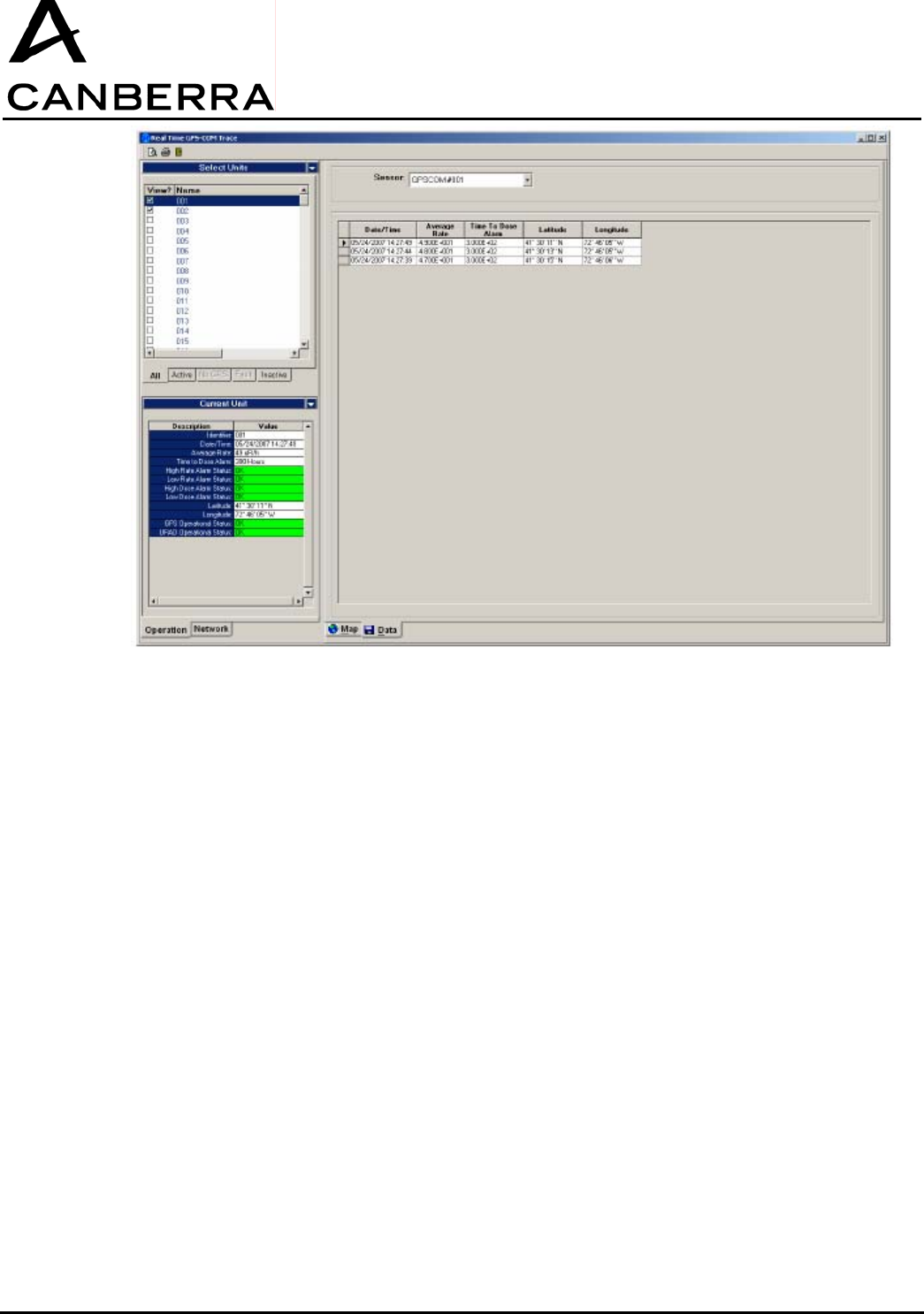
6.2. DATA VIEW
1) The Data View is accessed by clicking on the “Data” tab along the lower edge of the main portion of
the Real-Time GPSCOM Trace window.
2) Click the “Active” tab along the lower edge of the “Select Units” window on the lefthand side. To enable
viewing data from a specific unit, click the checkbox to the left of this unit’s name in the “Select Units”
listing.
3) Next, select the appropriate unit from the “Sensor” dropdown box at the top of the Data View window.
The time-tagged measurement and GPS position data from this unit will be displayed in the table
below.
4) To select a different unit in the Data View, repeat steps 2 and 3 above for the specific unit.
5) Clicking the checkbox adjacent to each unit in the “Select Units” list again will disable viewing the data
for those units.
USER MANUAL
GPS-COM
86378_A
19 / 32 CANBERRA Industries
800 Research Parkway
MERIDEN, CT 06450
7. SYSTEM OPERATION: DYNAMIC GPSCOM DEVICE CONNECTIONS
The RADACS-GPSCOM network is capable of connecting and disconnecting GPSCOM devices during
normal system operation. This functionality is particularly important for detecting new devices as they
appear on-site, or as they are transitioned between different sites and networks. The following
procedures describe the operation of the system in each case.
7.1. CONNECTING GPS-COM DEVICES
1) When a new GPSCOM device is switched on and enters communication range, it is automatically
detected by the Supervisor module.
2) The Supervisor notifies the RADACS server of the newly detected device, and alerts the system user
of this change in network status by automatically opening the Network Setup Wizard. The Network
Setup tab will appear on the lefthand side of the Real-Time GPSCOM Trace window on the RADACS
GPSCOM Console.
3) The newly detected device will be displayed in the “Detected List.” The system user must click on this
unit in the list to select it, and then accept it into the network by clicking the “>” button.
4) In the event that the network already contains its maximum of 200 active GPSCOM devices, the user
interface will report an error and request the system user to select a unit to remove from the “Accepted
List” before adding the newly detected device.
5) The Supervisor module will then attempt to connect the new unit to the network. If the connection is
successful, the new unit will then be added to the “Accepted List” of units. If the connection fails, a
failure message will be displayed in the Errors section at the lower portion of the Network Setup dialog
box and the unit will remain in the “Detected List.”
USER MANUAL
GPS-COM
CANBERRA Industries
800 Research Parkway
MERIDEN, CT 06450
20 / 28
86378_A
7.2. 7.2. DISCONNECTING GPSCOM DEVICES
In order for a GPSCOM device to transition from one network to another, it must first be disconnected
from its present network. This functionality provides a means for assigning GPSCOM units to individual
networks, and allows multiple GPSCOM systems to operate within close proximity to one another if
necessary.
1) To disconnect a specific GPSCOM device from the network, first click to select the unit name in the
“Accepted List” on the Network Setup tab of the Real-Time GPSCOM Trace window.
2) Next, move the unit from the “Accepted List” to the “Detected List” by clicking the “<” button.
3) The Supervisor module will then attempt to disconnect the unit from the network. If the disconnection is
successful, the new unit will then be moved to the “Detected List.” If the operation fails, a failure
message will be displayed in the Errors section at the lower portion of the Network Setup dialog box.
4) Once the unit has been disconnected from the network, the Blue “Link” status LED on the GPSCOM
unit will turn off. Note that a wait time of up to two minutes is required before reconnection to the same
or a different network can occur.
8. SYSTEM OPERATION: DYNAMIC SUPERVISOR/REPEATER MODULE CONNECTIONS
The RADACS-GPSCOM network allows for removal and insertion of Repeater modules if necessary to
extend the communication range of the system. The sections below describe the response of the
system and the required user interaction for different configurations and events.
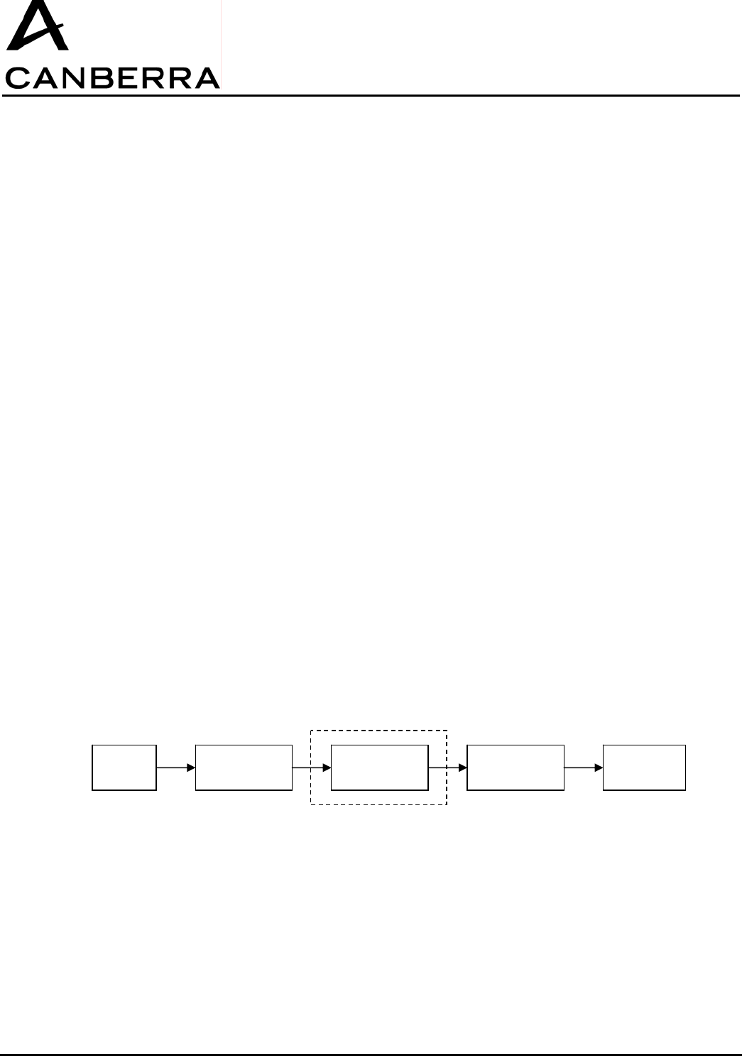
8.1. INSTALLING OR REMOVING REPEATER MODULES
In a system utilizing at least one Repeater module (Repeater-PC) and a Supervisor module, the
communication link established between GPSCOM devices and the Supervisor module is not affected
by adding or removing the Repeater-PC or Secondary-Repeater modules. All communication data for
the system is stored in the Supervisor, which will remain linked with the GPSCOM devices. Data flow
from the GPSCOM devices to the host computer will be momentarily interrupted if a Repeater module is
removed, but system operation will restore itself automatically once the communication chain has been
re-established.
PC Repeater-PC Secondary-
Repeater(s) Supervisor GPSCOM
Optional
USER MANUAL
GPS-COM
86378_A
21 / 32 CANBERRA Industries
800 Research Parkway
MERIDEN, CT 06450
8.2. REMOVAL OF A REPEATER-PC OR SECONDARY-REPEATER MODULE
1) Follow the steps in section 3.2.1 above to switch off and remove either a Secondary-Repeater or
Repeater-PC module.
2) All Repeater modules between the computer and the Repeater that has been removed will remain in
the network, and their Blue “Link” status LEDs will stay on. All Repeater modules after this point, along
with the Supervisor, will become disconnected and their “Link” status LEDs will turn off.
8.2.1. Insertion of a Repeater-PC or Secondary-Repeater Module
3) Follow the steps in section 3.2.1 above to install a new Secondary-Repeater module.
4) The Blue “Link” status LED of the newly installed Secondary-Repeater module will turn on to indicate
when it has been successfully synchronized and linked to the network.
5) If any downstream Repeaters and the Supervisor had been previously disconnected, their Blue “Link”
status LEDs will turn back on once the have automatically reconnected to the network.
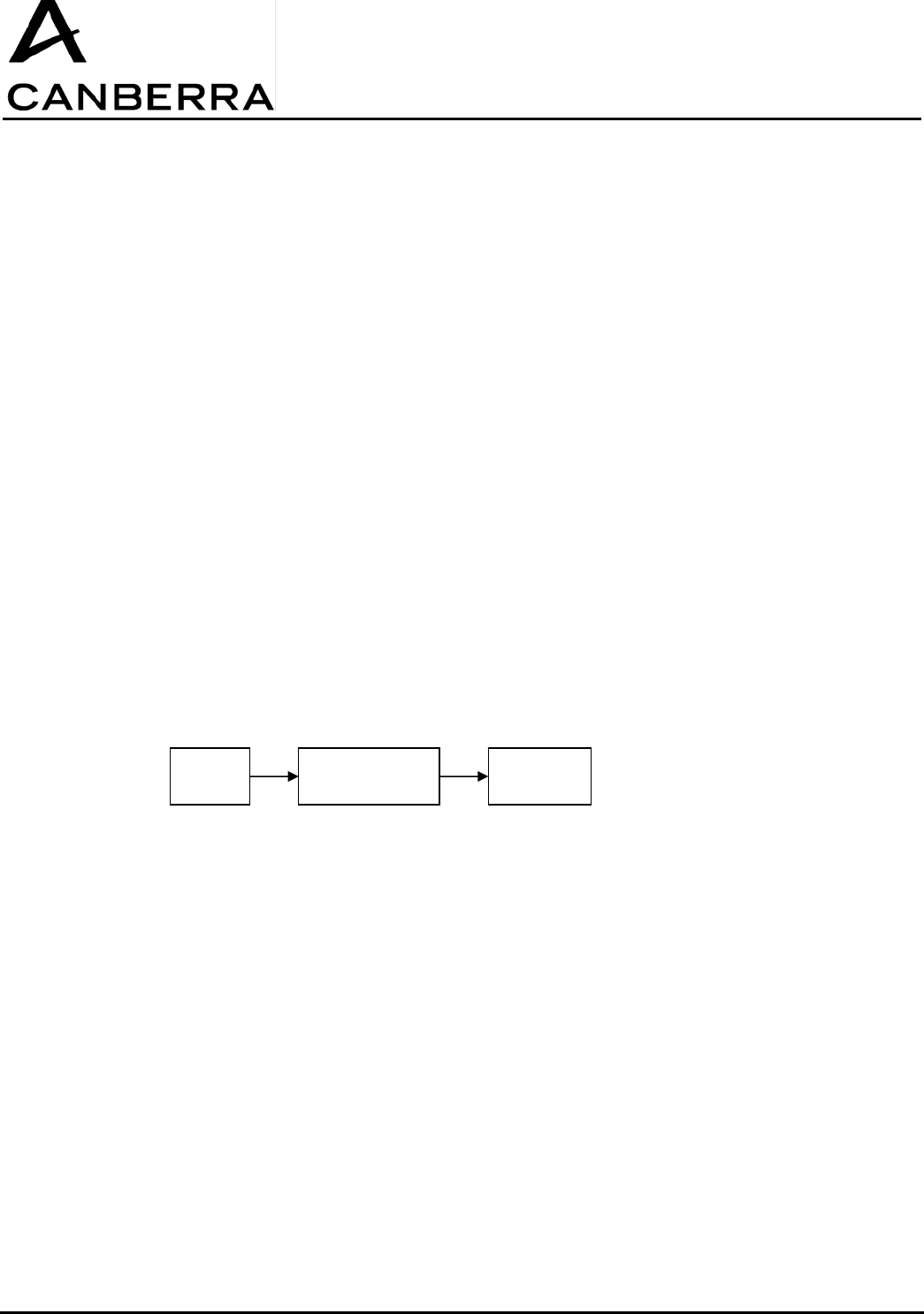
8.3. INSTALLING OR REMOVING SUPERVISOR MODULES
In a system containing only a Supervisor-PC module, it is not possible to insert additional Repeater
modules once the system is in operation without restarting and reconfiguring the system to some
extent. In this case, proper functionality of the system requires the system operating data and GPSCOM
communication table stored in the Supervisor to be reset. This occurs whenever the serial data cable is
disconnected from the Supervisor-PC, and the role of the module changes from Supervisor-PC to
standalone Supervisor.
8.3.1. Removal of a Supervisor-PC or Supervisor Module
1) Follow the steps in section 3.2.1 above to switch off and remove either a Supervisor-PC or Supervisor
module.
2) Any Repeater modules in the system will remain connected in the network, and their Blue “Link” status
LEDs will stay on. The Supervisor however will become disconnected from the network once it has
been switched off, and all system data in the Supervisor will be lost.
PC Supervisor-PC GPSCOM

USER MANUAL
GPS-COM
CANBERRA Industries
800 Research Parkway
MERIDEN, CT 06450
22 / 28
86378_A
8.3.2. Insertion of a Supervisor-PC or Supervisor Module
1) Follow the steps in section 3.2.1 above to install a new Supervisor module.
2) To restart the GPSCOM network, there are three possible procedures:
a) Shutdown and restart all the GPSCOM devices. Follow steps 3-9 in section 4 above to place
the Supervisor module into network scan/search mode, then scan and connect all GPSCOM
devices. This solution is the most straightforward, but may require a significant length of time
if the system contains a large number of GPSCOM devices.
b) If all of the identifiers of the GPSCOM devices previously connected are known are still stored
in the PC and GPSCOM-RADACS software, the following procedure may be used: Place the
Supervisor module into standby mode. Send a “connect” frame from the PC to each
GPSCOM previously connected. This solution is quick, but requires that the PC has stored the
identifiers of the connected GPSCOM devices.
c) Change the network number ID of the new Supervisor and all of the Repeaters in the system.
This solution requires the reconfiguration of all the Repeaters and Supervisor, and imposes
the retrieval of all of the deployed modules. It is therefore only practical in a network which
contains only one or two Repeaters maximum.
9. POWERING OFF THE SYSTEM
The following procedure describes the steps necessary to close the GPSCOM data and network
connections and power down the system hardware.
1) On the Network tab of the Real-Time GPSCOM Trace window, click the “Stop Data Acquisition” button
to end data transfer between the GPSCOM units and Supervisor module.
2) Next, click the “Stop GPSCOM System” button to stop all communication in the GPSCOM network.
3) To switch off each Supervisor/Repeater module, press and briefly hold the power button until all four
status LEDs turn on. After releasing the button, all status LEDS will turn off and the module will be
powered off.
4) To switch off each GPSCOM unit, press and briefly hold the power button until all four status LEDs turn
on. After releasing the button, all four LEDS will turn off and the GPSCOM will be powered off.
10. MAINTENANCE & SERVICE INFORMATION
This section describes the necessary maintenance of the GPSCOM hardware, and provides repair and
service contact information.
10.1. INTERNAL LITHIUM-ION BATTERIES
The GPS-COM handheld units and Supervisor/Repeater modules each contain a high-capacity Lithium-
Ion rechargeable battery pack for portable operation. Similar to all rechargeable batteries, the chemistry
of Lithium-Ion cells is such that they have an inherent self-discharging quality, which causes them to
slowly lose their energy even while in storage. For this reason, the internal batteries of GPSCOM
hardware should always be maintained in a charged state. Recharging the batteries before they have
been fully discharged does not present any damage to Lithium-Ion cells, since their internal “memory
effect” is minimal.
After each use, both GPSCOM and Supervisor/Repeater units should be recharged according to the
procedures in sections 3.1.3 and 3.2.3. Charging must be performed only within the ambient
temperature range listed in the Specifications section below.

USER MANUAL
GPS-COM
86378_A
23 / 32 CANBERRA Industries
800 Research Parkway
MERIDEN, CT 06450
10.2. REPLACEMENT COMPONENTS
The following components are available for direct replacement through the Canberra Service
department:
GPSCOM Devices:
AC/DC Power Adapter (5V@2A): TR15RA050 from CINCON ELECTRONICS CO., LTD
Supervisor/Repeater Modules:
AC/DC Power Adapter (5V@5A): TR30RA050 from CINCON ELECTRONICS CO., LTD
RF Antenna: code 85969
Antenna must not be removed nor replaced by another one.
11. DECLARATION OF CONFORMITY
11.1. EUROPE
Concerns RF868MHz devices
RF868MHz devices are compliant with the european R&TTE 1999/5/CE directive.
Complete declarations are available on request at
CANBERRA
ZI des Vauzelles
37600 LOCHES
FRANCE
11.2. US – FCC
Concerns RF915MHz devices.
These devices comply with Part 15 of the FCC Rules. Operation is subject to the following two
conditions: (1) these devices may not cause harmful interference, and (2) these devices must accept
any interferencereceived, including interference that may cause undesired operation.
These equipments have been tested and found to comply with the limits for a Class B digital device,
pursuant to part 15 of the FCC Rules. These limits are designed to provide reasonable protection
against harmful interference in a residential installation. These equipments generate use and can
radiate radio frequency energy and, if not installed and used in accordance with the instructions, may
cause harmful interference to radio communications. However, there is no guarantee that interference
will not occur in a particular installation. If these equipments do cause harmful interference to radio or
television reception, which can be determined by turning the equipment off and on, the user is
encouraged to try to correct the interference's by one or more of the following measures:
Reorient or relocate the receiving antenna.
Increase the separation between the equipment and the receiver.
Connect the equipment into an outlet on a circuit different from that to which the receiver is connected.
Consult the dealer or an experienced radio/TV technician for help.
The user may find the following booklet, prepared by the Federal Communications Commission, helpful:
How to identify and Resolve Radio/TV Interference Problems. This booklet is available from the U.S.
Government Printing Office, Washington, D.C. 20402, Stock No. 004-000-00345-4.

USER MANUAL
GPS-COM
CANBERRA Industries
800 Research Parkway
MERIDEN, CT 06450
24 / 28
86378_A
Pursuant to Part 15.21 of the FCC Rules, any changes or modifications to these equipments not
expressly approved by CANBERRA may cause, harmful interference and void the FCC authorization to
operate these equipments.
Operator may keep the equipment antenna at more than 20 cm from the body.
Supervisor/Repeater 915MHz can be used with a Class B Personal Computer and is also certified
under DoC “Declaration of Conformity” procedure.
12. SPECIFICATIONS
12.1. GPSCOM HANDHELD DEVICE
Environmental:
Operating Temperature Range -20oC to +60oC
Storage Temperature Range -30oC to +70oC
Humidity 0 to 95% at +35oC
Altitude 12000m (in transport only)
Specification IP67
Input Voltage:
Operating Range +4.5 to +5.5VDC
Maximum current 2A
Protection Polarity inversion
Disturbance (CEM)
Overvoltage (up to 12VDC)
Connector Fischer DEU 102 A002
Use only the power supply provided with the GPS Com:
Manufacturer: CINCON ELECTRONICS CO., LTD
Model: TR15RA050
Input: 100-240 V, 47-63 Hz, 0.4 A
Output: 5 Vdc, 2 A
Caution: The plug of the direct plug-in power supply is used as the disconnect device, it shall remain
accessible after installation.
Internal Battery:
Type Lithium-Ion
Operating time 30 hours minimum
Charging time 8.5 hours at -10oC

USER MANUAL
GPS-COM
86378_A
25 / 32 CANBERRA Industries
800 Research Parkway
MERIDEN, CT 06450
7.5 hours at +50oC
Lifetime 300 cycles
CAUTION: Risk of explosion if battery is incorrectly replaced. Replace only with the same or
equivalent type recommended by the manufacturer. Dispose of used batteries according to the
manufacturer's instructions
Communication:
Infrared
Compatibility IRDA 1.4
Connection Speed 9600 baud
GPS
Number of Channels 16
Precision 5 m (SEP)
Radio
Frequency 915 MHz (US), 868 MHz (EU)
Range 1000 m (unobstructed)
300 m (inside building)
Enclosure:
Dimension
Length 200 mm
Width 90 mm
Height 41 mm
Weight 372 g (0.82 lb)
Material ABS PC
Color Black
Cleaning Resistance Alcohol (90% solution)
Certifications & Approvals:
CEM/Radio 868MHz ETSI EN300-220-1 (EU), receiver class 3
ETSI EN301-439-3 (EU)
NF EN61326 (EU)
CEM/Radio 915MHz FCC 15-247 (US) FCC ID: VPMGPSC915 for GPS COM,
Electrical Safety 868MHz NF EN60950 (EU)
Shock & Vibration
Specification IEC 60068
Resistance 10m/s
2 (10-500Hz, 3-axis, 10 hours)
RoHS Compliant

USER MANUAL
GPS-COM
CANBERRA Industries
800 Research Parkway
MERIDEN, CT 06450
26 / 28
86378_A
12.2. SUPERVISOR/REPEATER MODULE
Environmental:
Operating Temperature Range -20oC to +60oC (on battery)
-20
oC to +50oC (battery charging)
Storage Temperature Range -40oC to +80oC
Humidity 0 to 95% at +35oC
Altitude 12000m (in transport only)
Specification IP66
Input Voltage:
Operating Range +4.5 to +5.5VDC
Maximum current 5A
Protection Polarity inversion
Overvoltage (up to 24VDC)
Connector Fischer DEU 104 A066
Use only the power supply provided with the GPS Com:
Manufacturer: CINCON ELECTRONICS CO., LTD
Model: TR30RA050
Input: 100-240 V, 47-63 Hz, 0.8 A
Output: 5 Vdc, 5 A
Internal Battery:
Type Lithium-Ion
Operating time 70 hours minimum
Charging time 13 to 17 hours
Lifetime 300 cycles
CAUTION: Risk of explosion if battery is incorrectly replaced. Replace only with the same or
equivalent type recommended by the manufacturer. Dispose of used batteries according to the
manufacturer's instructions
Communication:
Frequency 915 MHz (US), 868 MHz (EU)
Range 1000 m (unobstructed)
300 m (inside building)

USER MANUAL
GPS-COM
86378_A
27 / 32 CANBERRA Industries
800 Research Parkway
MERIDEN, CT 06450
Dimensions
Length 160 mm
Width 160 mm
Height 80 mm
Material Aluminium alloy
Color beige
Cleaning Resistance Alcohol (90% solution)
Certifications & Approvals:
CEM/Radio 868MHz ETSI EN300-220-1 (EU),
ETSI EN301-439-3 (EU)
NF EN61326 (EU)
CEM/Radio 915MHz FCC 15-247 (US) FCC ID: VPM-RS-915
Electrical Safety 868MHz NF EN60950 (EU)

USER MANUAL
GPS-COM
CANBERRA Industries
800 Research Parkway
MERIDEN, CT 06450
28 / 28
86378_A