Users Manual

1
CTS-HCOM-AA01 (EQ-PIO)
CTS-HCOM-AB01 (OHT-PIO)
* This device may have the possibility of radio interference during operation.
2016. 01. 08.(Ver1.2)
Hybrid-PIO Specification (RF, IR)

2
FCC STATEMENT
This device complies with part 15 of the FCC Rules. Operation is subject to the
following two conditions: (1) this device may not cause harmful interference, and (2)
this device must accept any interference received, including interference that may
cause undesired operation.
FCC ID: RMNCTS-HCOM
WARNING! Changes or modifications to this unit not expressly approved by the party
responsible for compliance could void the user’s authority to operate the equipment.
RF EXPOSURE WARNING! This equipment must be installed and operated in
accordance with provided instructions and the antenna(s) used for this transmitter
must be installed to provide a separation distance of at least 20 cm from all persons
and must not be co-located or operating in conjunction with any other antenna or
transmitter. End-users and installers must be provided with antenna installation
instructions and transmitter operating conditions for satisfying RF exposure
compliance.
Note: This equipment has been tested and found to comply with the limits for a Class
B digital device, pursuant to part 15 of the FCC Rules. These limits are designed to
provide reasonable protection against harmful interference in a residential installation.
This equipment generates, uses and can radiate radio frequency energy and, if not
installed and used in accordance with the instructions, may cause harmful
interference to radio communications. However, there is no guarantee that
interference will not occur in a particular installation. If this equipment does cause
harmful interference to radio or television reception, which can be determined by
turning the equipment off and on, the user is encouraged to try to correct the
interference by one or more of the following measures:
—Reorient or relocate the receiving antenna.
—Increase the separation between the equipment and receiver.
—Connect the equipment into an outlet on a circuit different from that to which the
receiver is connected.
—Consult the dealer or an experienced radio/TV technician for help.

3
[ Table of Contents ]
1 Product Overview ······························································ 3
2 Product Feature ································································ 3
3 Product Code Configuration ················································· 4
4 Input/Output Circuit ··························································· 6
5 Product Specification ························································· 7
6 Device Specification ·························································· 9
7 Connector Specification ···················································· 10
8 LED Display ··································································· 13
9 Major Pin Function ··························································· 14
10 Communication Medium Selecting Method ······························ 15
11 RF Function ··································································· 16
12 IR Function ···································································· 20
13 List of Serial Communication Commands ······························· 22

4
1. Product Overview
The CTS-HCOM Series is an integrated device that uses both RF communi-
cation in 2.4GHz and 5GHz and IR (Infrared light, optical) communication. It is
capable of choosing the stable communication media depending on the
surrounding conditions.
This product is a communication device to transmit and receive 8-bit data
contactlessly according to the SEMI-E84 protocol regulation.
It is possible to set many comfortable additional functions by the serial port or
the wireless communication. Also it is possible to change the communication
media from IR to RF and vice versa, depending on the noise level of surrounding.
Moreover, it provides various functions that find causes and solutions promptly
when there are abnormalities in transmitted/received data during the
communication.
This device is mainly for the exchange of the control signals between the
vehicle (Master or Active devices such as AGV/OHT) and the equipment (Slave or
Passive devices).
2. Product Feature
• The integration of RF (2.4GHz, 5GHz) and IR (Infrared light, optical)
communication in one device.
• The contactless exchange of the 8-bit input/output signals.
• The ability to choose the optimal communication media depending on the
surrounding condition.
• Wireless communication in 2.5GHz and 5GHz: Additional functions such as
data transmission/reception and F/W downloading.
• The maximum operational distance is 5m. (Only when there is no obstacles to
electromagnetic wave in the middle.)
• Designation of Wireless communication ID (address): 6 digits (ASCII code)
• Storage of various data using a large-capacity SRAM: Up to about 130
operations including data and errors, standard time, signal intensity, etc. (The
SRAM is cleared when the power is off.)
• Additional functions using a serial port: Changing the settings, receiving real-
time communication data, F/W downloading, etc.
5
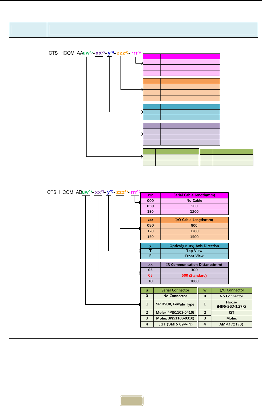
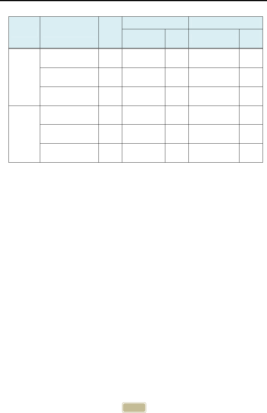
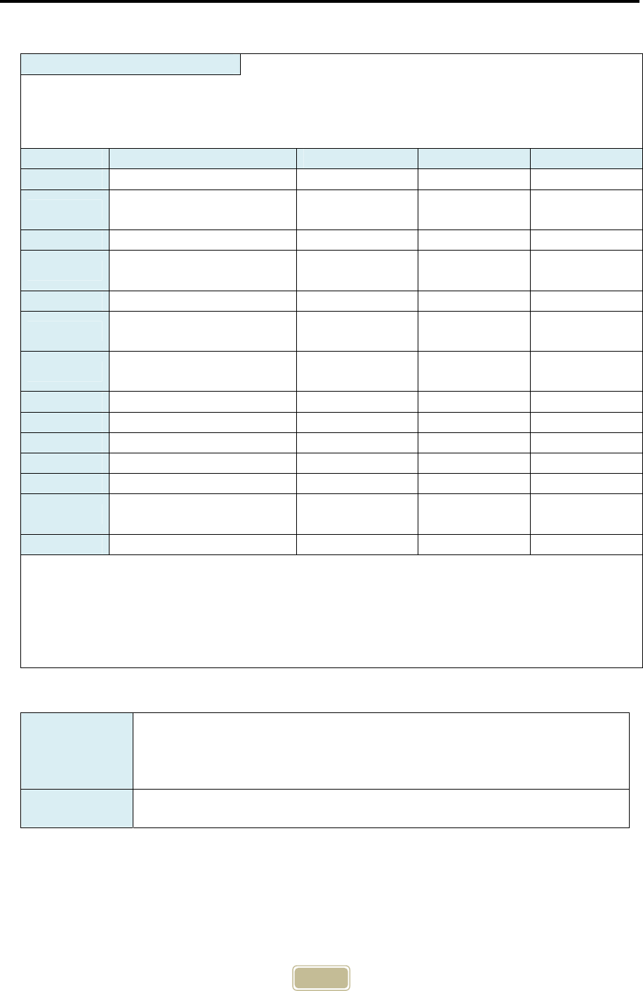
3. Product Code Configuration
Usage Product Code Configuration
Equipment
(EQ)
OHT
(VHL)
1000
500 (Standard)
30003
05
10
xx IR Communication Distance(mm)
Front View
Top ViewT
F
yOptical(Tx, Rx) Axis Direction
3000
2500
1500150
250
300
zzz I/O Cable Length
1500150
300
No Cable000
30
rrr Serial Cable Length(mm)
No Connector0
Serial Connectoru
No Connector
0
I/O Connectorw
9P DSUB, Female Type125P DSUB, Male Type
1
6
Example of Product Code
Usage Product Code
Optical
Axis
Direction
Serial Cable Data Cable
Connector Type Length
(mm) Connector Type Length
(mm)
Equipment
(EQ)
CTS-HCOM-AA10-
05-T-250-050 Top DSUB9P 500 None 2500
CTS-HCOM-AA11-
05-F-250-050 Front DSUB9P 500 DSUB 25P
(#4-40UNC) 2500
CTS-HCOM-AA11-
05-T-150-050 Top DSUB9P 500 DSUB 25P
(#4-40UNC) 1500
OHT
(VHL)
CTS-HCOM-AB10-
05-T-250-050 Top DSUB9P 500 None 2500
CTS-HCOM-AB21-
05-F-080-050 Front Molex 4P
(53375-0410) 500 Hirose
(HIF6-26D-1.27R) 800
CTS-HCOM-AB44-
05-T-120-120 Top JST 1200 AMP 1200
7
RF-PIO
Inside
INPUT
+24V VCC
PIO
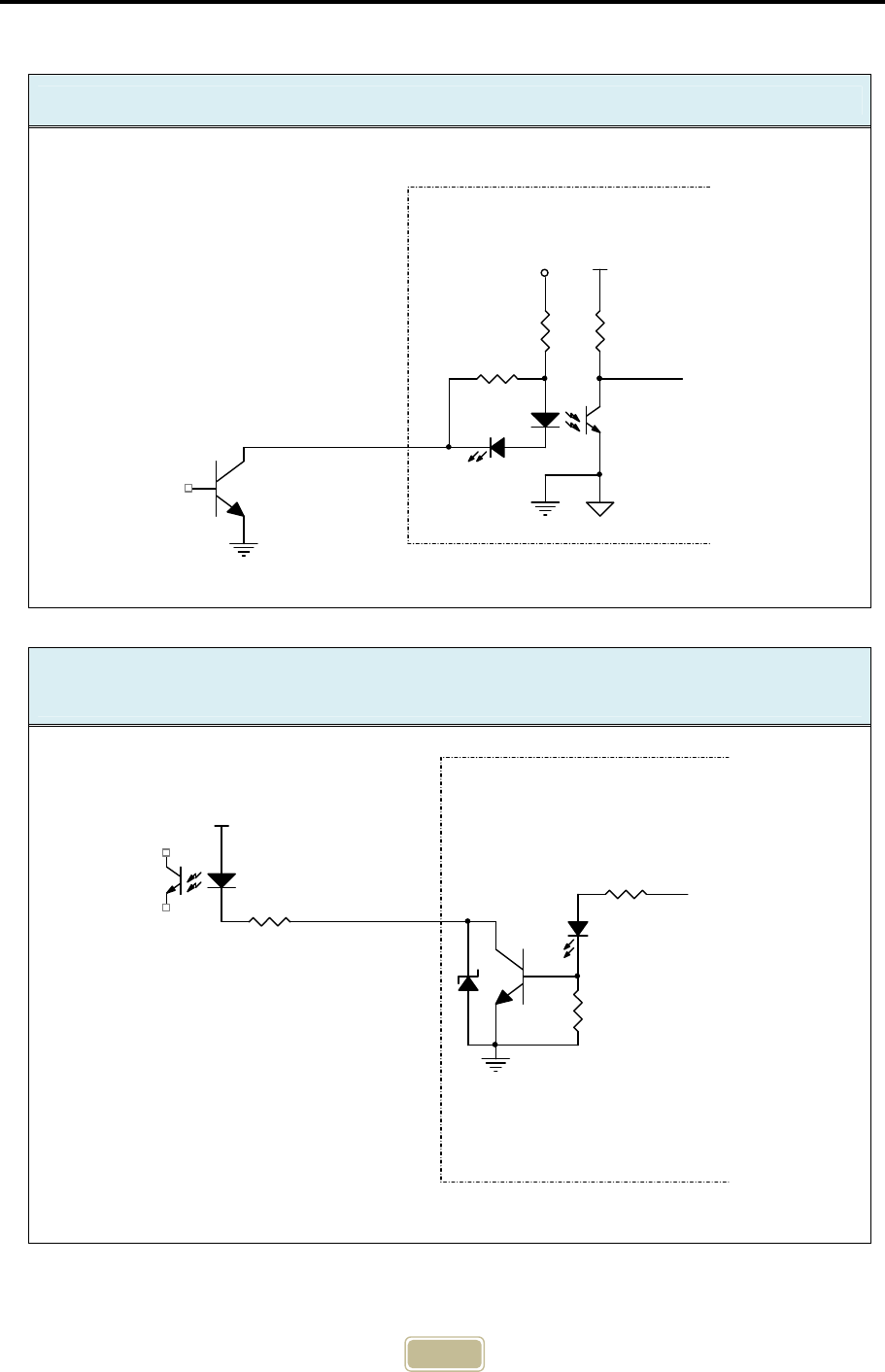
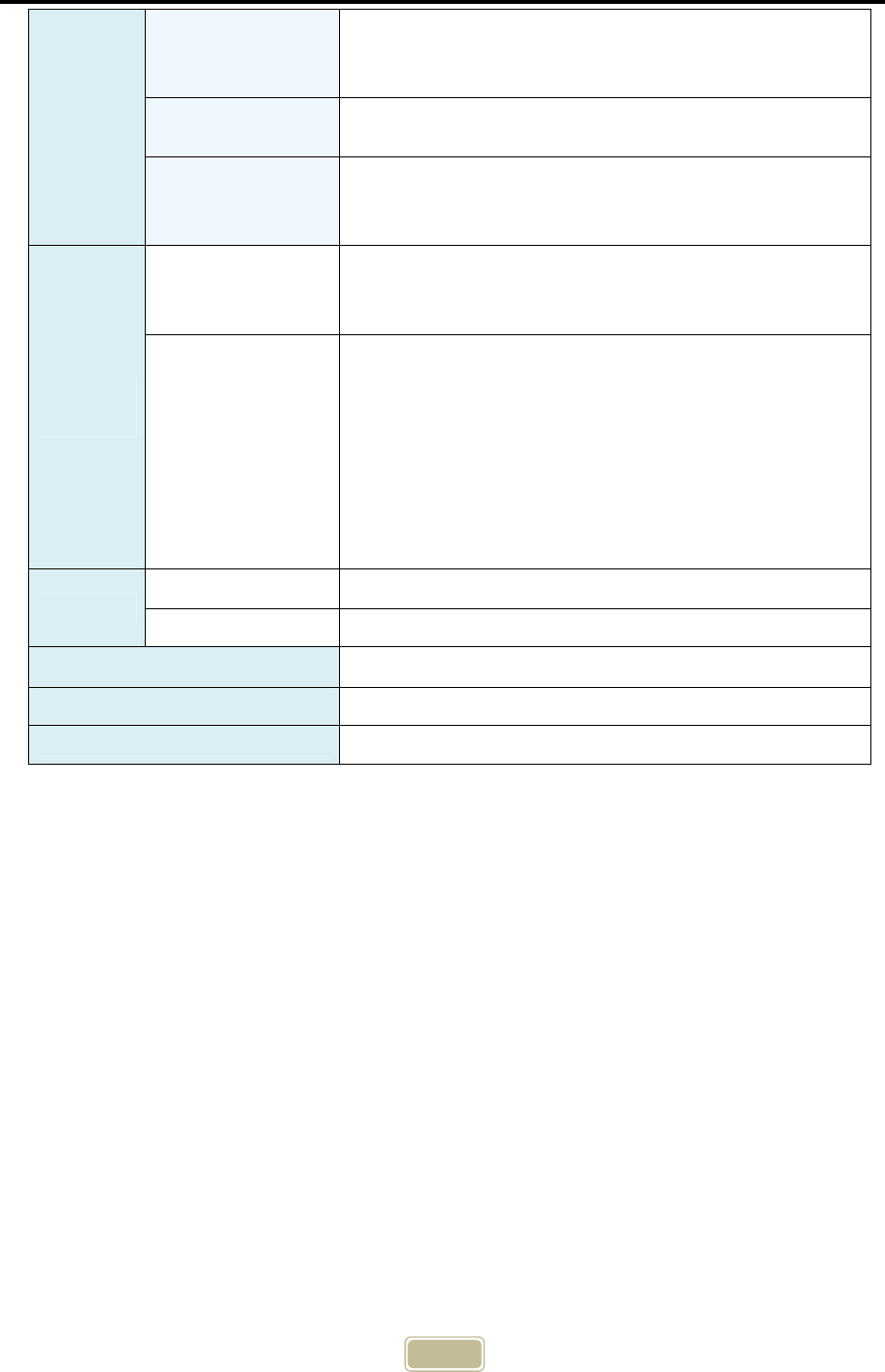
4. Input/Output Circuit
Input Signal : Maximum 10mA
Output Signal :NPN Open Collector, maximum driving current is 50mA / 30V
VCE max. 100mV / 10mA
RF-PIO
Inside
OUTPUT
DCV
PIO

8
5. Product Specification
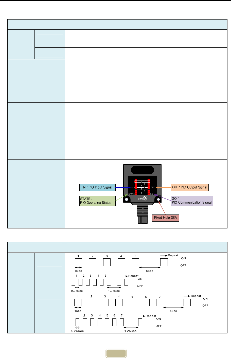
Division Specifics Content
Display
GO ON when the RF or IR communication between a
master (OHT, AGV) PIO and a slave (EQ) PIO begins.
STATE FLASHS as watchdog signals showing operation status.
IN Displays the operation status of 8-bit input port
OUT Displays the operation status of 8-bit input port
External
Equipment
Connection
Connector
(Optional)
AA01 Model(Slave) : 25-pin DSUB, No Connector.
AB01 Model(Master) : Hirose 26-pin, JST, Molex,
No Connector
Cable 26AWG x 22C + 24AWG x 3C, Foil Shield
Input 8 Bit, Photo-Coupler, 24V
On : 10mA, Off : 0.1mA or less
Output 8Bit, Open Collector, NPN, 30V
Maximum operating current: 50mA
IR
Commu-
nication
Major Function 8-bit I/O Communication
Communication Media 870nm, Infrared
Transmission Distance 0.5m (0°), 0.25m (+15°, -15°)
Directional Angle 30° (±15°)
Transmission Method 1:1 Transmission, Half Duplex
Optical Axis
Direction
T Type : Pointing TOP
F Type : Pointing FRONT
Optical
Modulation Type Pulse Modulation
Transmission
Error Check Parity
Transmission
Period
About 24ms when linked, about 85ms when
disconnected.
RF
Commu-
nication
Major Function 8-bit I/O communication, downloading F/W and
communication data, changing the settings, etc.
Communication
Media 2.4GHz, 5GHz ISM Band, bandwidth 1MHz
Freac-
ency
Band
2.4GHz 2.403~2.480GHz, 78 channels*1)
5GHz 5.728~5.825GHz, 95개 channels*1)
Safety Function Serial number confirmation function, CRC-16
Transmission Method 1:1 transmission, Half Duplex
ID Setting PIO serial number to avoid an interference with
neighboring PIOs, which is composed of 6 digits (ASCII)
9
Channel Setting
Transmission frequency to avoid an interference with
neighboring PIOs, which is composed of 3 digits
(ASCII).
ID Setting Method Serial communication command (Set as default when
released)
Operational
Distance
5m@0dBm
(Only when there is no obstacles to electromagnetic
wave in the middle.)
Environ-
ment
Storage
Environment
Temperature: -25 ~ 70°C
Humidity: 5 ~ 95%RH
(There shall be no dew condensation.)
Operating
Environment
Ambient brightness(When using IR) :
4000lx or less (Incandescent lamp, fluorescent lamp)
*) Install it such that no external light may enter the
receiver.
Temperature : 0 ~ 40°C
Humidity : 35~85%RH
(There shall be no dew condensation.)
Vibration : 4~150 Hz, 4.9m/s2 or less
Power Input Voltage DC 24V±10%
Supply Current 130mA or less @ 24V
Case Material Polycarbonate
Dimension (WHD) 505320mm (Excluding the cable overhang)
Weight About 300g (CTS-HCOM-AA01-05-T-150)
*1) Can be used in an environment without frequency interference with other
wireless devices such as wireless LAN, Bluetooth, etc.
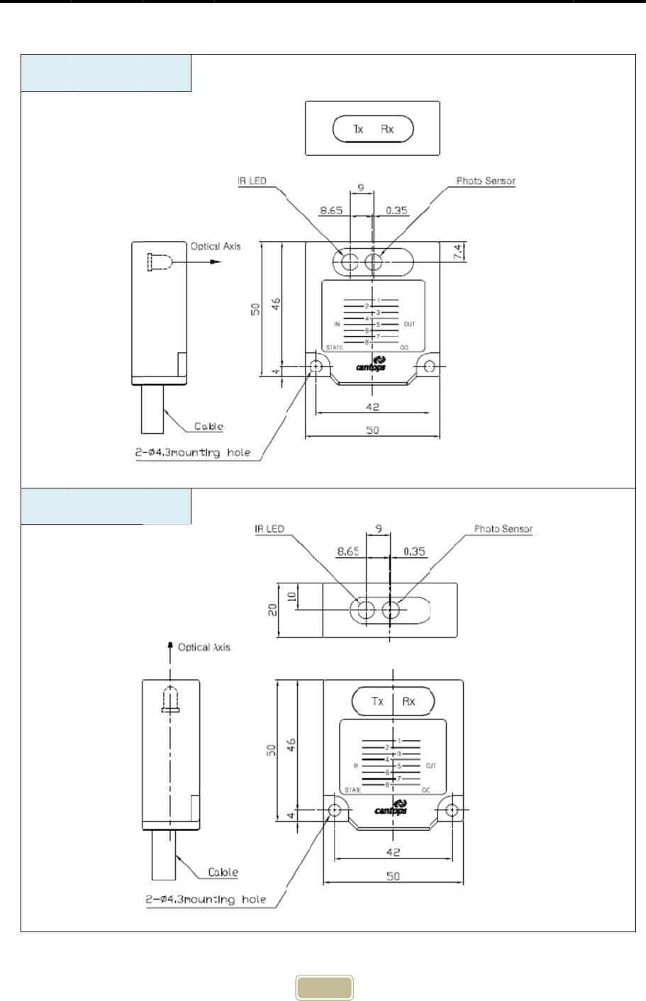
6. Devic
F Typ
T Ty
p
e S
p
ecif
i
e :
Pointing
p
e :
Pointin
g
T
i
cation
FRONT
g
TOP
T
o
p
Front
10
Unit : mm
Unit : m
m
m
11
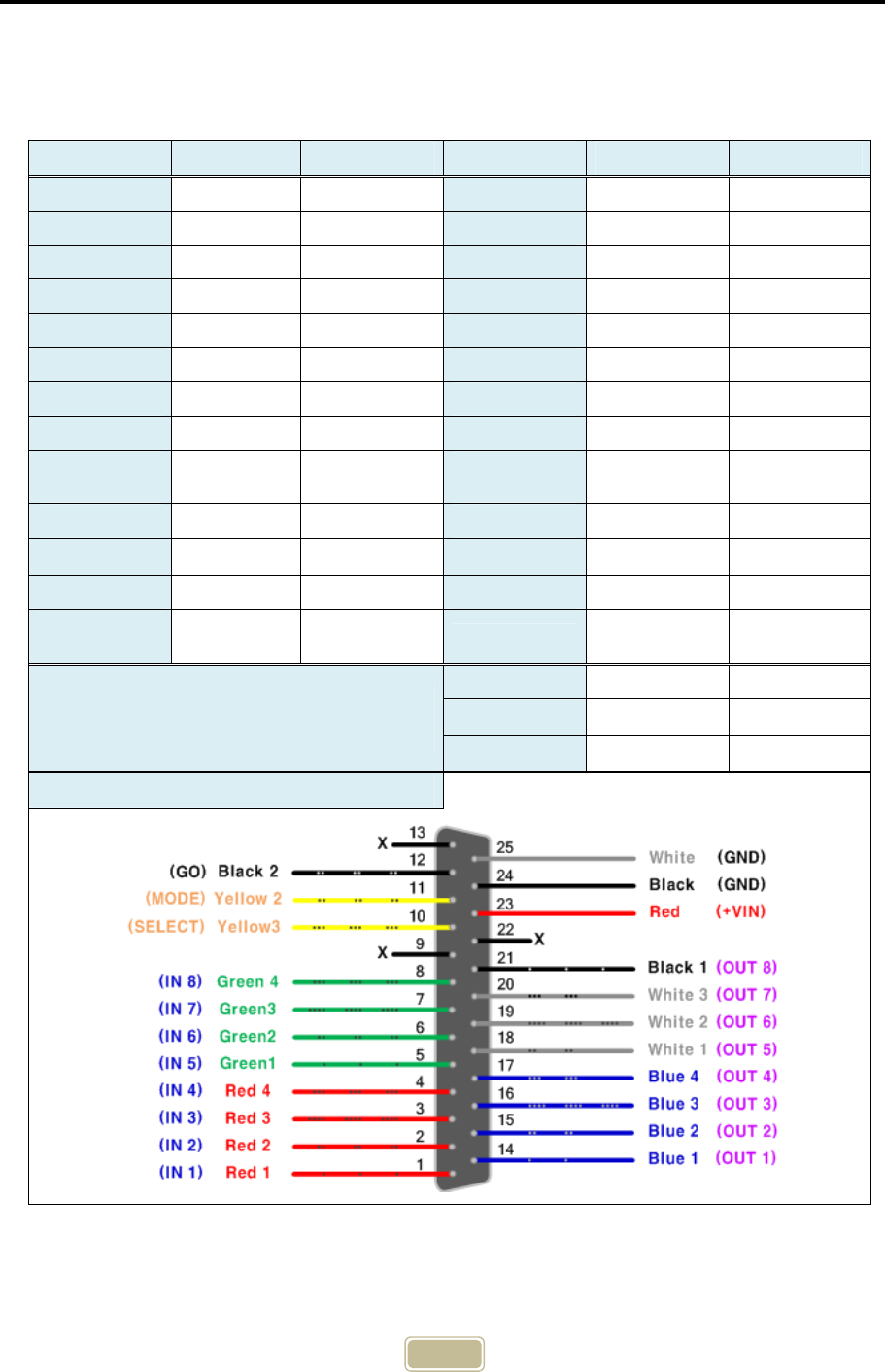
7. Connector Specification
1) For Equipment (CTS-HCOM-AA01) : Slave, DSUB 25-pin, Pin Type, Maximum
cable length is 10m.
Function Pin No. Color Function Pin No. Color
IN 1 1 Red 1 OUT 1 14 Blue 1
IN 2 2 Red 2 OUT 2 15 Blue 2
IN 3 3 Red 3 OUT 3 16 Blue 3
IN 4 4 Red 4 OUT 4 17 Blue 4
IN 5 5 Green 1 OUT 5 18 White 1
IN 6 6 Green 2 OUT 6 19 White 2
IN 7 7 Green 3 OUT 7 20 White 3
IN 8 8 Green 4 OUT 8 21 Black 1
Not
Connected 9 X Not
Connected 22 X
SELECT 10 Yellow 3 +VIN 23 Red
MODE1) 11 (GND) Yellow 2 GND 24 Black
Go (Ready) 12 Black 2 GND 25 White
Not
Connected 13 X x x
Serial Port
(DSUB 9-pin, Female)
TxD 2 Black
RxD 3 Brown
GND 5 Red
Cable Connection Diagram
1) Mode pin(11) is connected to GND inside so no additional connection is needed.
12
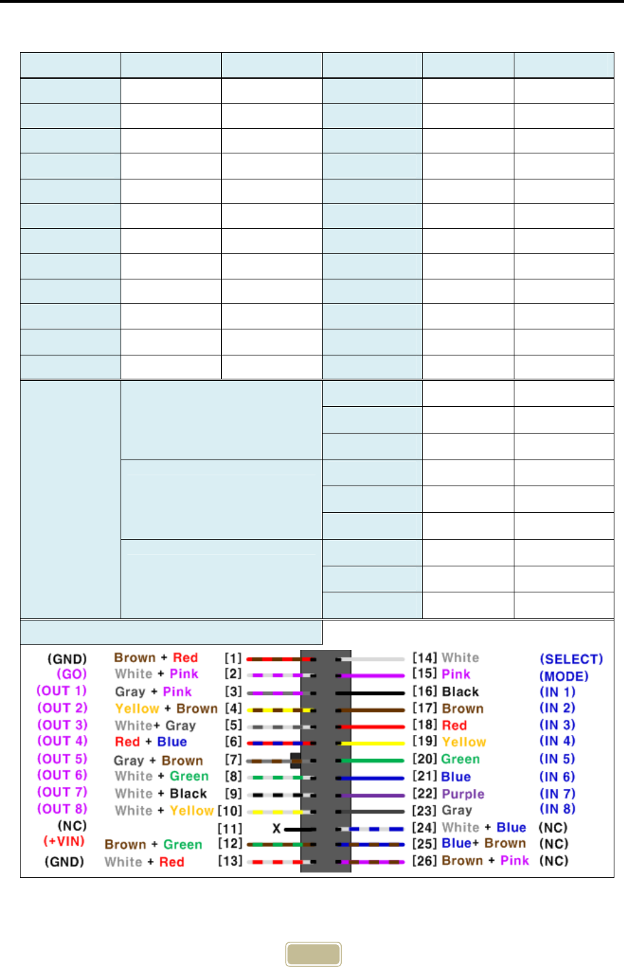
2) For OHT (CTS-HCOM-AB01), Master
Hirose 26-pin, 1.27mm IDE Connector
Function Pin No. Color Function Pin No. Color
IN 1 16 Black OUT 1 3 Gray + Pink
IN 2 17 Brown OUT 2 4 Yellow + Brown
IN 3 18 Red OUT 3 5 White + Gray
IN 4 19 Yellow OUT 4 6 Red + Blue
IN 5 20 Green OUT 5 7 Gray + Brown
IN 6 21 Blue OUT 6 8 White + Green
IN 7 22 Purple OUT 7 9 White + Black
IN 8 23 Gray OUT 8 10 White + Yellow
SELECT 14 White Ready (Go) 2 White + Pink
MODE 15 Pink +VIN 12 Brown + Green
X 11, 24 X GND 1 Brown + Red
X 25, 26 X GND 13 White + Red
Serial Port
DSUB 9-pin, female
TxD 2 Black
RxD 3 Brown
GND 5 Red
Molex 4P
(5557-04R)
TxD 1 Black
RxD 2 Brown
GND 3 Red
Molex 3P
(51103-0300)
TxD 1 Black
RxD 2 Brown
GND 3 Red
Cable Connection Diagram
13
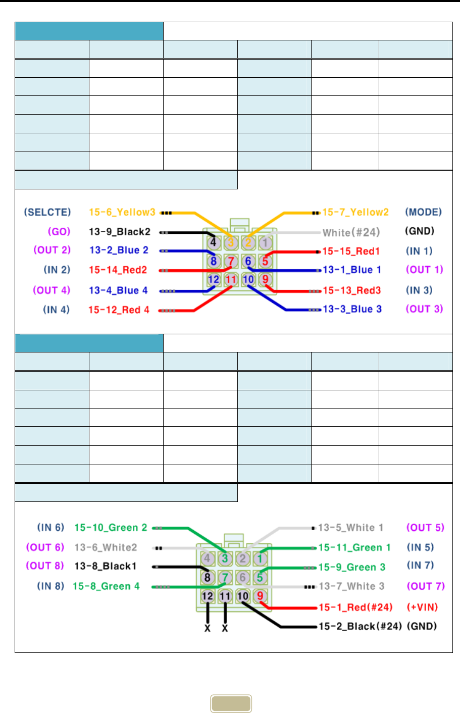
AMP 12-pin, 172170
A Connector
Function Pin No. Color Function Pin No. Color
IN 1 5 Red 1 OUT 1 6 Blue 1
IN 2 7 Red 2 OUT 2 8 Blue 2
IN 3 9 Red 3 OUT 3 10 Blue 3
IN 4 11 Red 4 OUT 4 12 Blue 4
SELECT 3 Yellow 3 Ready (Go) 4 Black 2
MODE 2 Yellow 2 GND 1 White
Cable Connection Diagram
B Connector
Function Pin No. Color Function Pin No. Color
IN 5 1 Green 1 OUT 5 2 White 1
IN 6 3 Green 2 OUT 6 4 White 2
IN 7 5 Green 3 OUT 7 6 White 3
IN 8 7 Green 4 OUT 8 8 Black 1
X 11 X +VIN 9 Red
X 12 X GND 10 Black
Cable Connection Diagram
14
8. LED Display
LED Name Display Content
1~8
IN Indicates the operation status of input circuit inside of PIO, which is
ON when the input is LOW.
OUT Indicates the output status inside of PIO, which is ON when TR is ON.
GO
Turns ON when there is data transmission/reception between a
master and a slave PIOs.
The maximum time that GO LED and output remain OFF after
the wireless communication is disconnected is 775ms. This can
be adjusted by user through <R> command.
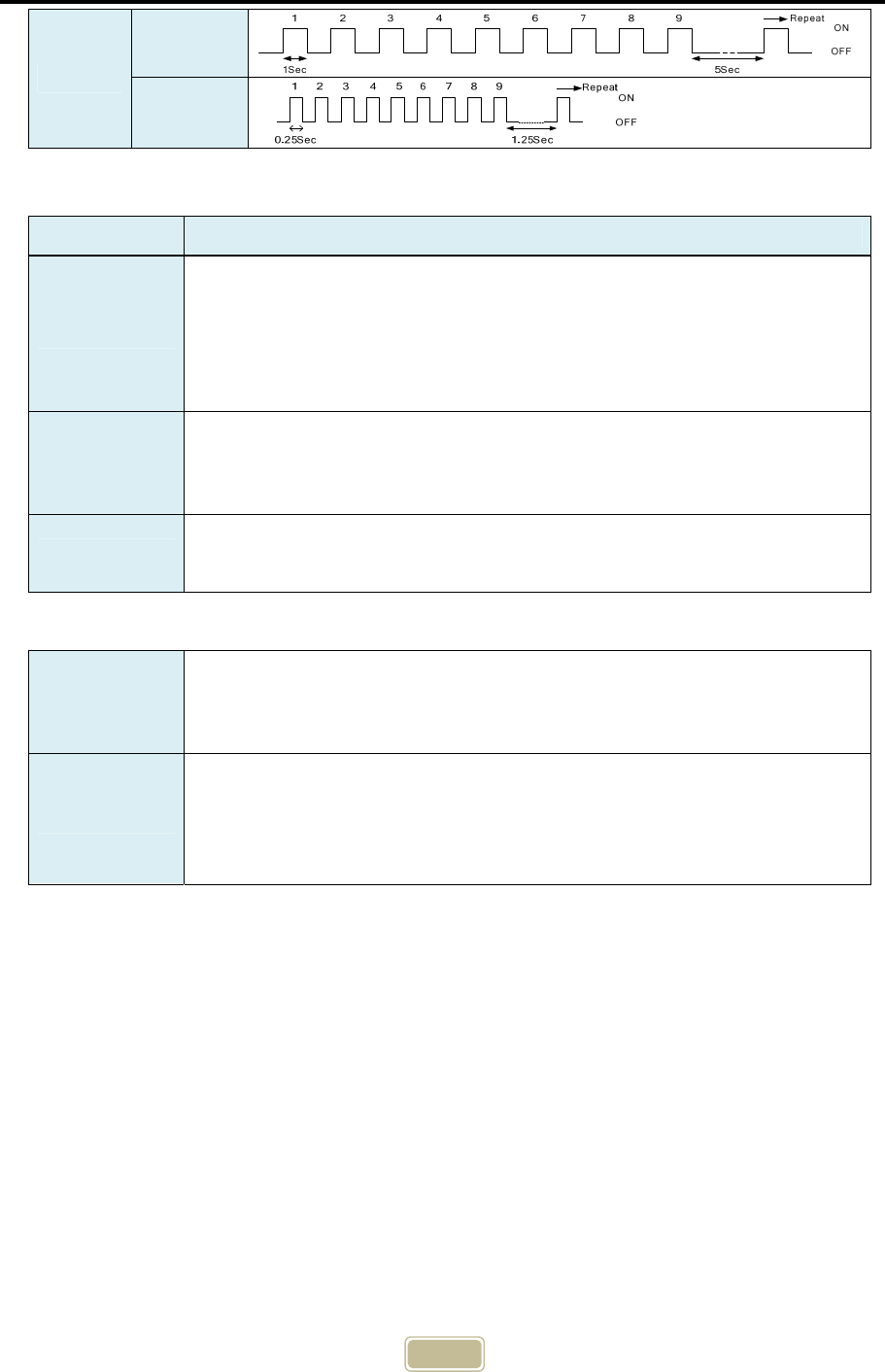
STATE1)
Used as watchdog signal to check whether there is an
abnormality in the product.
▪ RF mode: Blinks with periods of Master mode (0.25 sec),
Slave mode (1 sec), standby mode (0.1 sec).
▪ IR mode : Similar to that of RF mode, but has different
blinking periods.
※ Operation modes are distinguishable. See the diagram below.
*) LED Diagram
1) STATE LED Operation Timing
Mode Period Graph
IR
Slave
Master
2.4G
Slave
Master
15
9. Major Pin Function
Signal Name Usage
Mode (Input)
Input to select a mode of PIO
▪ GND : Slave Mode (EQ, Connected to GND inside of PIO so no
additional connection is necessary.)
▪ OPEN : Master Mode (OHT)
Select (Input)
Input to operate the PIO
▪ GND : Stops a wireless communication of PIOs.
▪ OPEN : Operates a wireless communication of PIOs.
GO (Output) Turns ON if there is a normal communication between a master and a
slave PIOS.
Modes
Master Mode Transmits data from input port wirelessly if PIO is operated by
OPENing the Select signal. This mode is used by OHT or AGV.
Slave Mode
Even though PIO is operated by OPENing the Select signal, does not
transmit but only receives optical signals. Transmits data from input
port wirelessly when receives optical signals from the master. This
mode is used by equipment.
5G
Slave
Master

16
10. Communication Medium Selecting Method
This product has two contactless communication media: the optical (infrared light)
and the wireless communication (2.4GHz, 5GHz RF). There can be a communication
interference in the semiconductor factories because of surrounding equipment or
sensors. If this happens, this product provides a stable communication by selecting
the other medium without an interference.
A communication medium can be selected by the serial communication command
(M command). In case of wireless communication (RF), the distinct channel ID and
other variables must be set.
17
11. RF Function
RF Communication
Characteristics
RF communication using ISM (Industrial Scientific and Medical) Band of 2.4GHz and
5GHz that can be used without an authorization.
High-speed data communication - 1Mbps per channel.
GFSK modulation, 1MHz bandwidth.
A great expandability provided by the function selecting the serial numbers of 6
bytes and frequencies of 3 bytes.
Channel occupation time is about 1ms (Communication period: 25ms). Minimizes
the interference between other wireless devices.
Setting the channel without conflict is necessary because of the frequency
interference with 2.4GHz and 5GHz wireless LEN and other wireless devices.
Maximum RF output power: 0dBm
Sensitivity of the receiver : -90dBm
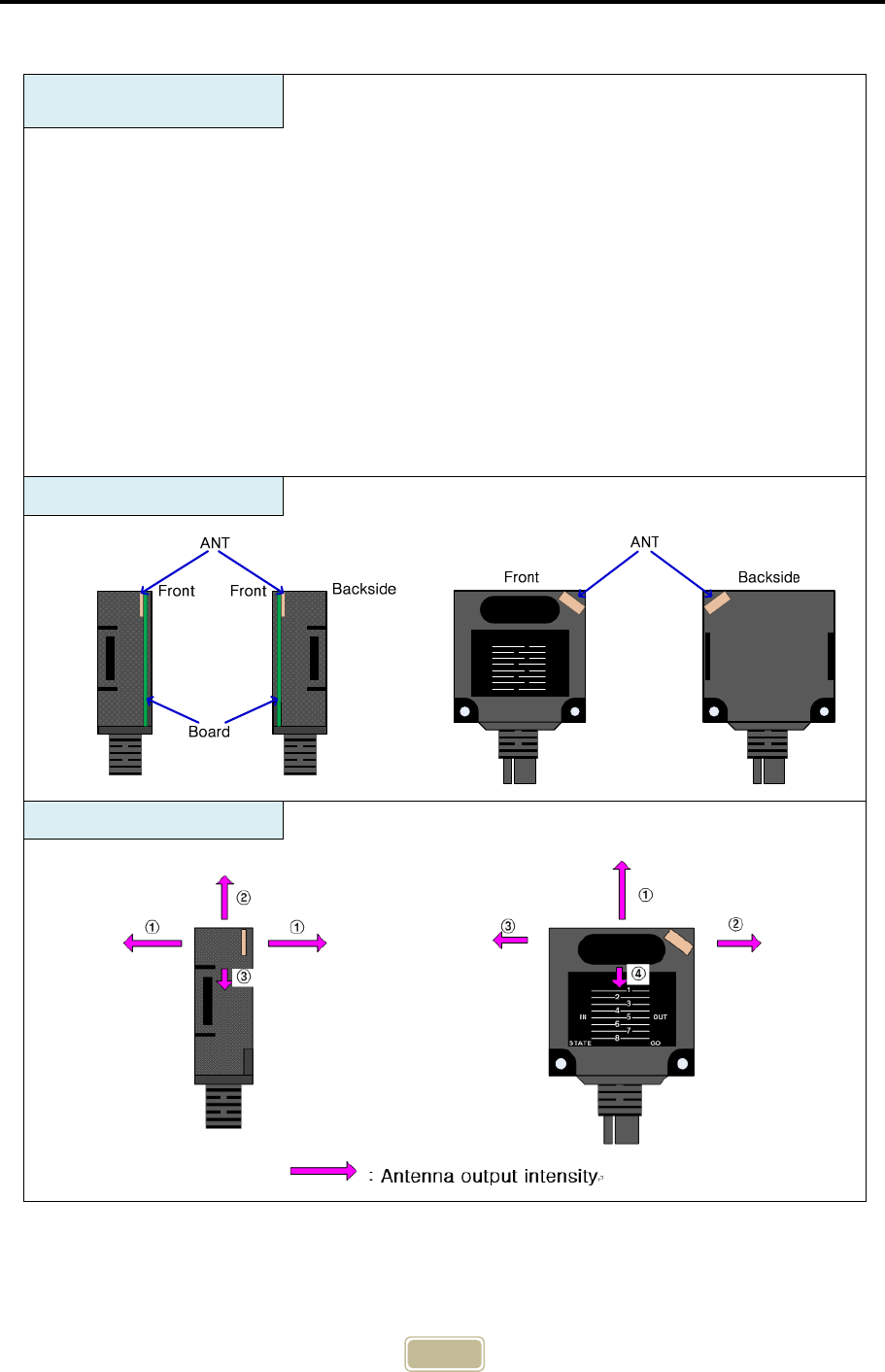
Antenna Configuration
Emission Pattern
8
1
2
3
4
5
6
7
STATE GO
OUTIN
18
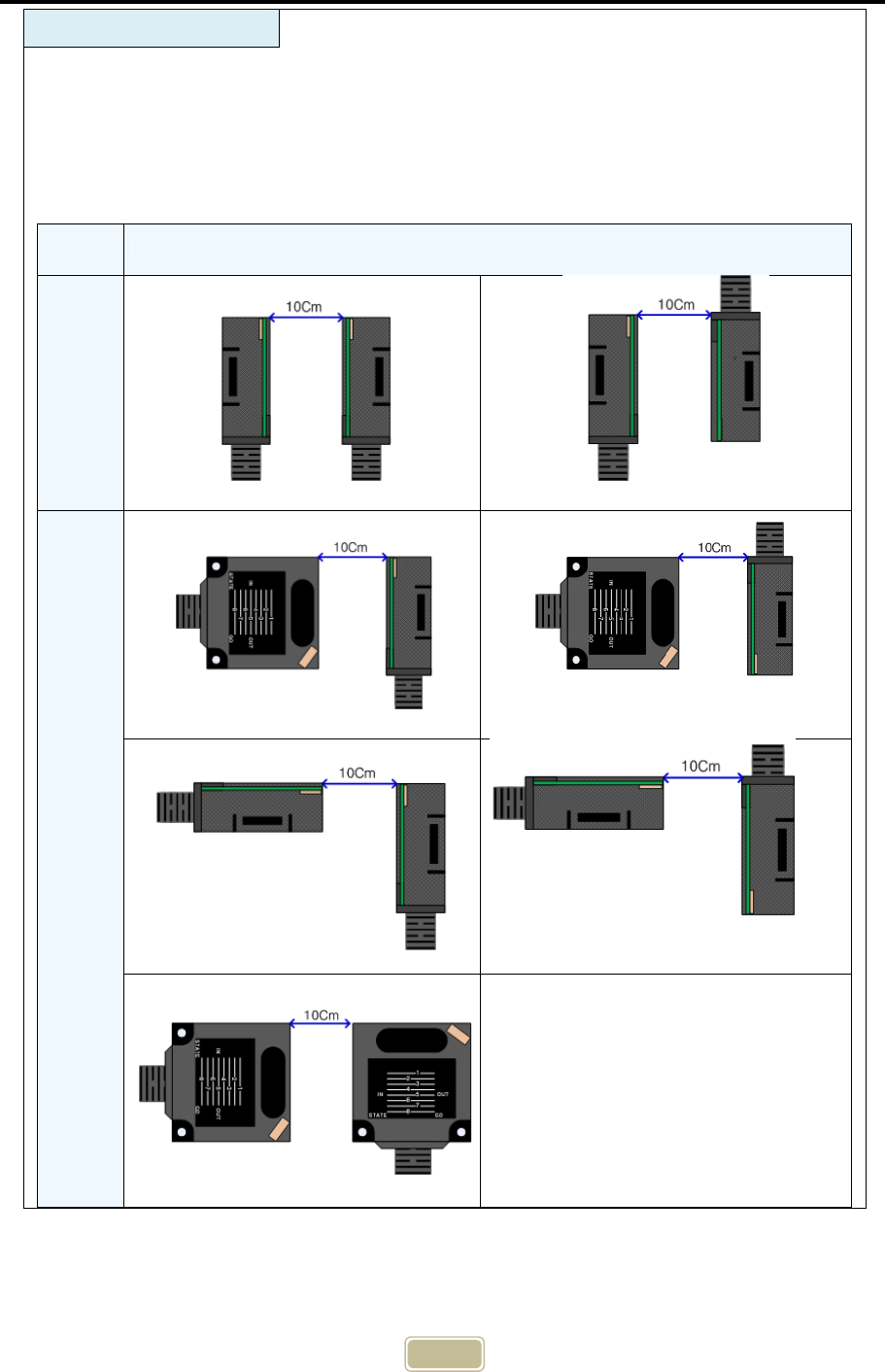
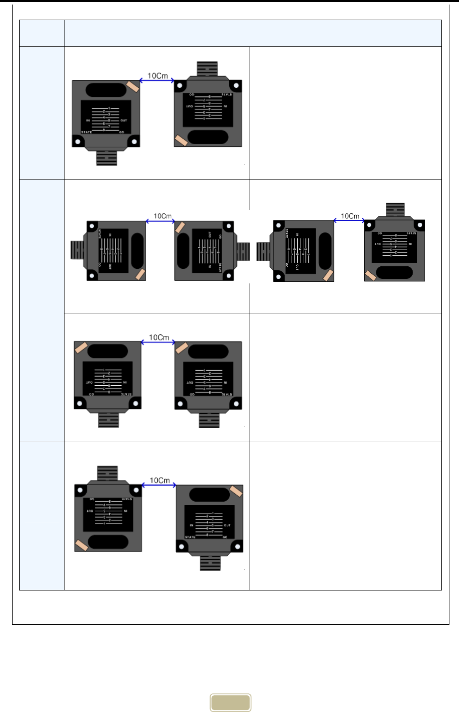
How to install
These are the examples of the damping ratios depending on directions of the
master and slave PIOs in 10cm. See the values as the relative values with error of
measurement. Like the diagrams below, the reception sensitivity can be vary
depending on the directions, even in such a short distance. This can influence the
performance of RF communication. Therefore, check the optimal conditions for RF
communication before the installation of PIOs.
Damping
Ratio Installation Direction
-25dB
-30dB
-
19
Dampting
Ratio Installation Direction
-33dB -
-35dB
-
-37dB -
20
12. IR Function
Precautions for Installation
1) Metals, mirrors and other objects existing in a space at the straight-line distance
between two sensors reduce the communication performance. Remove the obstacles
on the path if possible.
2) You can use it stably without communication errors when there is no interference with
other wireless devices in an open space.
3) There may be no metals or other obstacles within a 60mm radius around this antenna.
4) There may happen frequency interference due to other RF devices around. Use this in
an environment without frequency interference for stable operation.
5) Especially, when using this together with a device using a 5GHz band, allocate a
channel by avoiding overlaps.
6) Maintain a 20cm or more interval between PIOs for equipment.
Wireless Environment Setting
The wireless communication (RF) function of CTS-HCOM Series can be
simultaneously connected to many devices due to its characteristics. In order to
communicate with one device (equipment), the ID and CH(channel) of the
communication counterparty (For equipment, Slave PIO) shall be set before starting
communication with the vehicle (OHT, Master PIO). The ID and CH setting is possible
using serial communication commands.
PIO Setting Method
Slave
▪ Connect to PIO serial port => Set by a communication
commands (ID and CH, transmission power etc.)
▪ The set data is stored in the memory, so it doesn’t need
to be set again even though power is turned OFF.
Master
▪ Connect to PIO serial port => Set by a communication
commands (No. of VHL/Communication Medium/ID/CH/PORT)
▪ In case of Select OFF(Communication Permitted) ON
(Communication Prohibited), the IC and CH are changed
to defaults. The No. of VHL, communication medium, ID,
CH, PORT must be reset before Select OFF.
※ If it is not ready for data transmission, it does not
transmit data even though it becomes Select OFF.
※ For more information, see the Serial Communication Specification.
21
IR Communication
Characteristics
Wavelength : 870nm (Infrared light, Optical)
Ambient brightness : 4000lx or less of incandescent light and fluorescent light,
the place without direct light
Transmission/reception method : Half Duplex
Modulation : Pulse Modulation
Operational distance and angle : 0.5m at 0°, 0.25m at ±15°
Adjustment of communication distance : Serial/RF communication command
Adjustment of reception level : Serial/RF communication command
(To eliminate surrounding noises if any.)
Input signals and GO output filtering : Is possible to set the time by the serial
command.
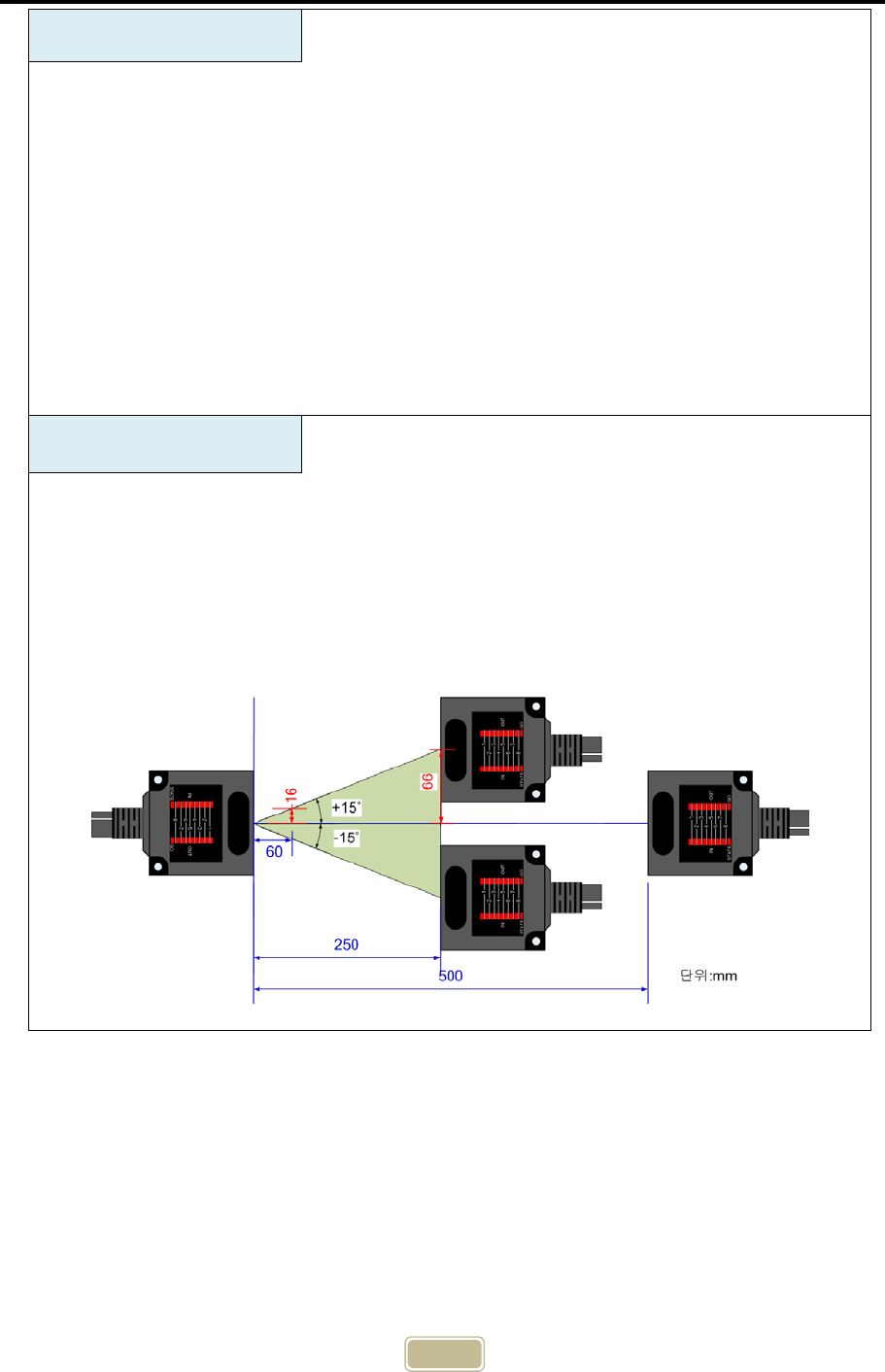
IR Radiation
Characteristics
As shown in the figure below, the communicable angle is 30°, and
communication is possible from a 0.25m away distance at ±15° and from a
0.5m away distance at 0°. If light, sunshine, IR remote controller, optical
sensor, etc. applies light directly to the transmission/reception window, loss of
communication may happen. In this case, block the external light and then use
it.
Unit : mm
22
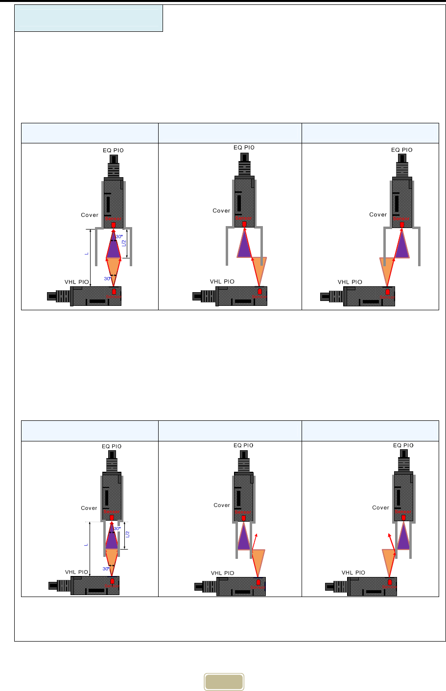
Considerations for installation
This product uses both IR and RF communication. In case of IR (optical and infrared
light) communication, the performance declines if light is blocked by fixed brackets or
parts since it uses invisible infrared light. As shown in the figure below, when PIOs of
VHL stop without error or within the range of ±15°, surrounding objects shall not block
the light of PIOs.
Stop without error Stop at 15 degrees to the right Stop at 15 degrees to the left
The cases of the light of PIO is blocked by the surrounding objects are shown in
diagrams below. In these cases, there is high possibility of PIO communication error
depending on where VHL stops. If a VHL stops without error, the PIO communication
will operate normally. However, if it stops with error, communication error can happen
becuse light is blocked. Therefore, be careful when install the fixed equipment and
surrounding devices.
Stop without error Stop at 15 degrees to the right Stop at 15 degrees to the left
Also, if there is optical noise, it is necessary to block the noise using the fixed objects.
23
13. List of Serial Communication Commands
How to set commands
• Serial Communication Setting Value: 38400,8,n,1, No flow control
• The first letter of every commands is “<” and the last letter is “>”.
• The first letter of responds for commands is “[“ and the last letter is “]”.
Command Function Medium1
)
Master2
)
Slave2
)
M Set the communication medium IR/RF Maintain Maintain
R The number of trials for
stable connection IR/RF Maintain Maintain
T Set the current time IR/RF Reset Reset
Y Check whether it is ready to
communicate IR/RF - -
G Check the GO status IR/RF - -
L Download
the communication data IR/RF -
(Function N/A)
-
(Available)
S Download the status of the
communication data IR/RF -
(Function N/A)
-
(Available)
V Check the version IR/RF - -
C Set the channel RF Reset Maintain
A Set the ID RF Reset Maintain
N Set the PORT number RF Reset Unused
P Intensity of RF radiation RF Maintain Maintain
W Time to check whether
there are other devices. RF Maintain Unused
O The number of OHT RF Maintain Unused
1) Whether to use the set values is dependent on media (optical or wireless)
2) Whether to save the set values (If the set value is saved, it maintains this value even
though the power is off.) is dependent on the mode (Master/Slave), so be careful when
use serial commands.
※ Use the serial communication program provided by CanTops to enter the commands.
About A Serial Command Setting for Different Modes
Master Mode
Setting the No. of OHT, communication medium, ID, CH, and No. of
PORT is only possible when SELECT is ON (Communication
prohibited). Other commands can be used at any time through the
serial communication.
Slave Mode Serial commands can be used at any time, regardless of SELECT
status.
※ See “Serial communication specification” for more detailed information.
*) The specification of this product may change without notice to improve performance
of the product.
* Rev Information

24
Document
Ver. Date Modified content
V 1.0 2015.8.6
▪ Maximum value of Go signal: 375ms => 775ms (p.11)
▪ Period of standby mode of STATE LED: 0.05 => 0.1초
▪ Display the number of blinks of STATE LED depending on media
- Only for IR : 3 times
- RF Mode, when IR operates : 5 times
- RF Mode, when 2.4GHz operates : 7 times
- RF Mode, when 5GHz operates : 9 times
▪ Modification in part of formats
▪ Addition of cable (Master) AMP for OHT
V1.1 2015.9.7 ▪ Addition of the item number code format
V1.2 2016.1.8 ▪ Addition of the RF patterns and installation method depending on
the damping ratios. (p. 16, 17, 18 are added.)