Users Manual

RFID Reader
(4 channels, EtherCAT )
Operation manual
CTS-STBR-AA Series (Ver 1.1)
CTS-STBR-AA
2
1. Outline
This product is a RFID Reader which can read the tag (Transponder) of ISO 11785 standard using
134.2KHz. This is a product which is optimized in such a way that it can stably be operated in a
diversity of noise environment, and it is used for logistics of semiconductor line.
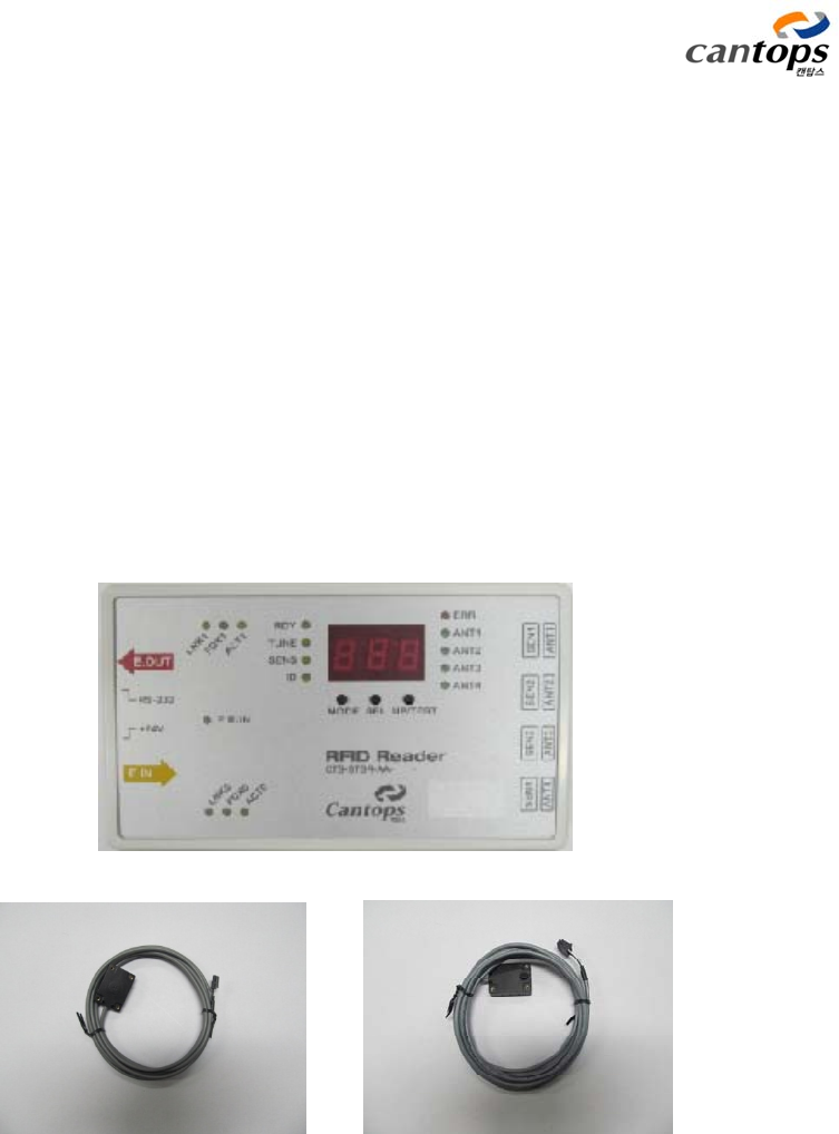
The product is constituted with reader, antenna, and sensor as shown in <Fig. 1>. <Fig. 1-b>
shows the antenna which is used together with the reader, and a specialized antenna can also be
developed and used in accordanced with application. <Fig. 1-c> shows the sensor detecting FOUP,
and for further information, please refer to the specification of sensors.
For this product, network function is strengthened so that ID and sensor information required
for overall factory logistics can be collected and managed in real time by utilizing ethernet based
industrial filed bus called EtherCAT.
( a ) RFID reader
( b ) Antenna ( c ) FOUP detecting sensor
<Fig. 1> Shape of reader and antenna

CTS-STBR-AA
3
☞ During the operation of reader, a high voltage of more than 200V
is generated at the antenna. Therefore, cares shall be taken as
there is a danger of electric shock if the wire around the antenna
is touched. In addition, there is also the danger of electric shock
when any part(s) at the case inside is touched. Never touch any
part(s) at the board inside.
☞ Reader and antenna are in the optimally adjusted state to suit to
the product of our company. If using another product, it can be
the cause of part breakdown.
☞ In accordance with the type of this company’s antenna, the setup
value of the reader will be different, therefore, confirm the antenna
which can be connected to the reader before the use.
☞ The frequency used by this reader is 120~140KHz. In order to use
this product under the optimum state, install it at the location
where the electric wave of this frequency band is not generated
from surrounding appliances or equipments.
!
Caution

CTS-STBR-AA
4
Main specification and installation environment of this product are shown in the following <Table
1>.
<Table 1> Main specification for RFID reader and antenna
Classification Detailed item Description
Reader
Frequency 134.2KHz
Reading time*1) 150ms / Page
Writing time 390ms / Page
Maximum reading distance 80mm (There are differences in accordance
with the types of antenna.)
Maximum writing distance 35mm (There are differences in accordance
with the types of antenna.)
The number of connected antenna Maximum 4 units
The number of sensor input Maximum 8 units (2 units/antenna channel),
filtering function
Firmware Upgrade EtherCAT communication
Additional function Opening of antenna, detection of sensor
abnormality, auto tuning, etc.
Cable of antenna
Diameter 3mm
Bending diameter 45mm
Length 0.1M ~ 3M (Optional item, in the unit of
10cm)
Material PVC
Head section of
antenna
Size 4330.5x12mm
Material Polycarbonate, black color
Connector 43650-0200 (MOLEX)
Type of tag RI-TRP-DR2B 17Page64bit, Read/Write
Specification for
communication
RS-232C 1 CH, Full Duplex, for the purpose of
setting up
Field Bus EtherCAT, 100MHz
Protocol CoE, FoE, etc.
Manually operating
section
LED indicating section 16 units, indicating mode and operating
state
7 Segment indicating section 3 units, ID, used for tuning
Manually operating switch 3 units, for manually installing the reader
without PC

CTS-STBR-AA
5
Environment and
safety
Storing environment
Temperature: -25 ~ 70°C
Humidity: 5 ~ 95 %RH (However, there shall
not be any condensing phenomenon.)
Operating environment
Temperature: 0 ~ 50°C
Humidity:35~85 %RH (However, there shall
not be any condensing phenomenon.)
Withstand voltage More than 500V
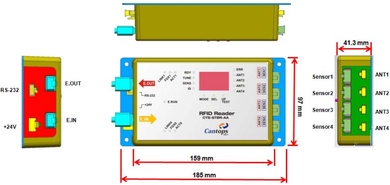
Power source Input voltage DC 20V ~ 26V, 400mA
Size (WHD) 1859741.3mm (Excluding the protruding
section of connector)
Material of case Fixing plate:SCP1(Steel)???
Main body: Polycarbonate
Weight Approx. 460g ???
CTS-STBR-AA
6
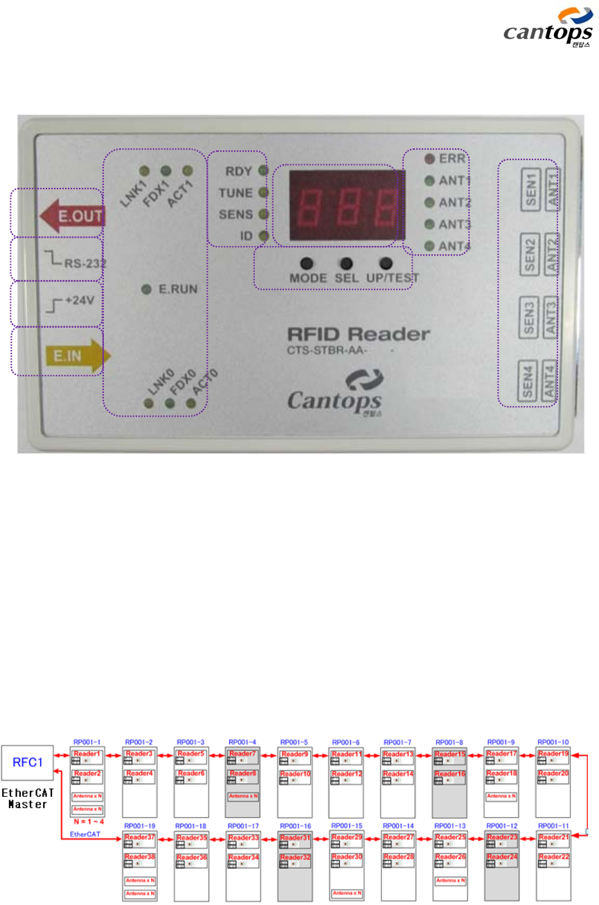
2. Function for each section
<Fig. 2> Arrangement diagram of main parts
2.1 EtherCAT connector and indicating section
EtherCAT communication configuration, which connects ethernet communication line with the
shape of daisy chain as shown in <Fig. 3>, is an industrial ethernet communication standard of
conducting real time communication with 100MHz. In order to have this kind of daisy chain shape
wiring, there are 2 communication ports in a reader, and E.IN is connected to E.OUT of the
previous reader, and E.OUT is connected to E.IN of the next reader.
<Fig. 3> Basic configuration diagram of EtherCAT system
①
②
③
④ ⑤
①
①
CTS-STBR-AA
7
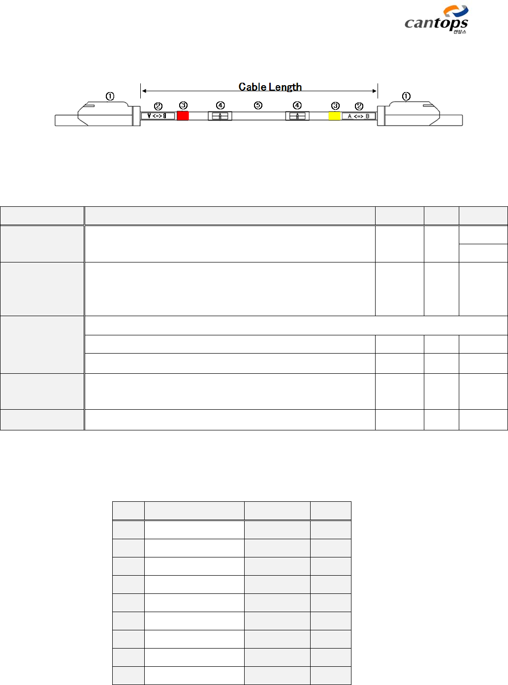
Communication line is constituted with the shape as shown in the following <Fig. 4>.
<Fig. 4> Configuration diagram of EtherCAT cable
<Table 2> Specification of cable parts
Wiring diagram of EtherCAT cable is as shown in the following <Table 3 >.
<Table 3> Wiring diagram of EtherCAT cable
CN1 Color Function CN2
1 Yellow Tx+ 1
2 Orange Tx- 2
3 White Rx+ 3
4 N.C - 4
5 N.C - 5
6 Blue Rx- 6
7 N.C - 7
8 N.C - 8
Shell Shield braiding wire Shield Shell
Description Specification Maker Q`ty Remark
① Plug 6GK1 901-1BB10-2AA0 Siemens 2EA CN1
CN2
② Label 1
Starting point (A), indicating the ending point (B), thermally
shrunken transparent tube, attached to the location 10mm
away from the connector end
③ Classification
of input/output
port
Attaching color tape at the cable end (Tape width is 10mm.)
Input: Yellow 1EA
Output: Red or orange color 1EA
④ Label 2 Starting point (A), indicating the ending point (B), thermally
shrunken transparent tube, attached to the side of ②
⑤ Cable AWG#22, 2Pair, SFTP, Profinet Type B Siemens 1EA
CTS-STBR-AA
8
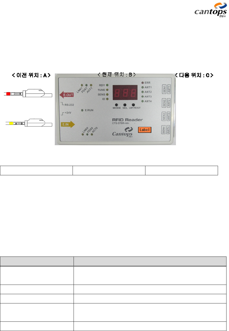
The items to be careful about when connecting the communication line are that the
inscription marked at the starting point (A) and ending point (B) of cable shall be corresponded
to the unit number attached to the reader, and connection shall be made as shown in <Fig. 5> so
that the colors (red and yellow) indicated at the cable shall be agreed with those of E.OUT(red)
and E.IN(yellow) located at the case of the reader.
<Previous position: A> <Current position: B> <Next position: C>
<Fig. 5> Connection method of EtherCAT cable
Operation state of EtherCAT is indicated with the 7 units of state indication LEDs.
From the E.RUN LED, connecting state of EtherCAT communication port can be grasped as follows.
E.RUN State
Off When EtherCAT is at INIT which is the initial communication
state
Slowly flickering When curret state is at Pre-OP mode
Lighted once When curret state is at Safe-OP mode
Continously turned on When it is in normal operation mode after completing
initialization
Rapidly flickering When it is in bootstrap mode
CTS-STBR-AA
9
LNK0(E.IN) and LNK1(E.OUT) LED indicate following state for each of the ports.
LNK0, or LNK1 State
Off When communication line is not connected
Flickering When EtherCAT communication is underway as
communication line is connected
Continously turned on When it is the state of connection only without
communication
FDX0 and FDX1 are the function of indicating communication velocity, and in the case of EtherCAT,
it uses the communication velocity of 100MHz as the basis, therefore, under the normal
connecting state of EtherCAT communication line, the continously turned on state shall always be
maintained.
ACT0(E.IN) and ACT1(E.OUT) indicate following state for each of the ports.
ACT0, or ACT1 State
Off When communication line is not connected
Flickering When EtherCAT communication is underway as
communication line is connected
Continously turned on When it is the state of connection only without
communication
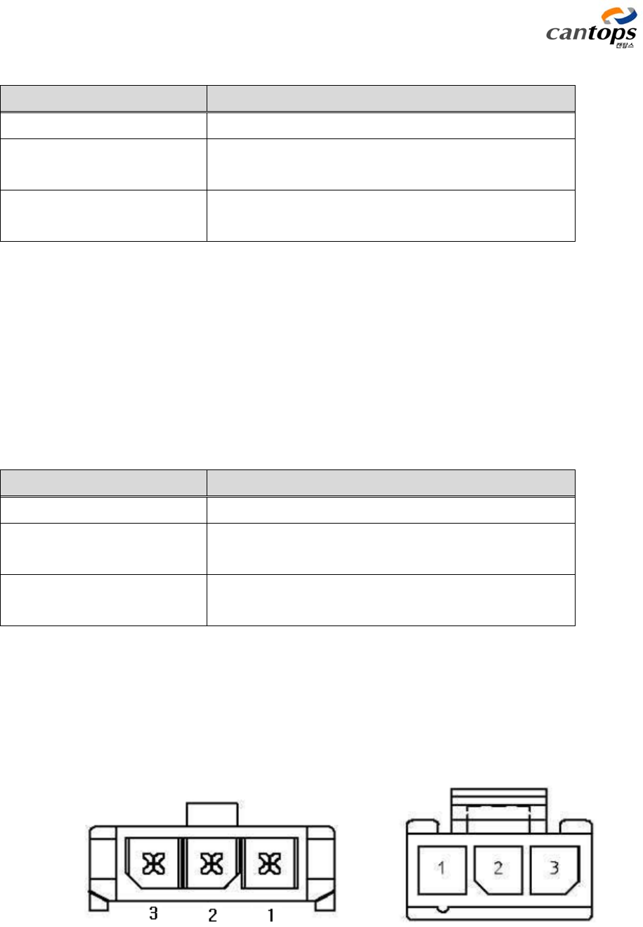
2.2 RS-232C communication connector
This is a serial communication port in which the reader is connected with PC for simple
setup and state confirmation without using EtherCAT communication. The connector used in
the connection is 43650-0300(Molex). For pin arrangement and function, refer to <Table 4>.
(a) Header : Reader (b) Receptacle : Cable
<Fig. 6> Arrangement of pin number of RS-232C communication port
CTS-STBR-AA
10
<Table 4> Arrangement of RS-232 connector pin
Reader
Function TxD RxD GND
Number 2 1 3
Computer/high
rank
Number 1 2 3 4 5 6 7 8 9
Function x RxD TxD x GND x x x x
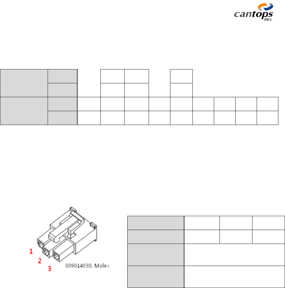
2.3 Power input connector
Power source applied to reader is DC +24V, and pin numbers are as shown in the following
Figure.
<Fig. 7> Power input
connector
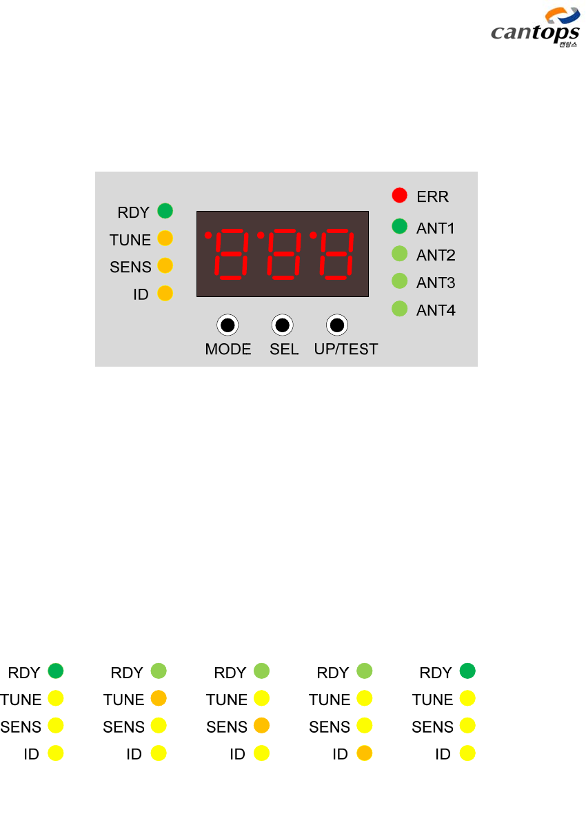
2.4 Manually operating section
This is the operating section which is used when tuning the antenna for displaying the highest
performance of RFID Reader and setting the noise environment analysis function and ID required
for communication with host. This is a convenient function which can verify all functions with the
reader itself without PC so that setup can easily be conducted at the job site.
Operation state of reader is indicated with 4 LEDs located at the left side of the manually
operating section, and ID number and a variety of states are indicated with 7 sgment located at
Pin number 1 2 3
Function FG GND +24V
Name of
connector 39303035, Molex
Connector for
cable 039014030, Molex
CTS-STBR-AA
11
the middle, and the antenna channel under operation is indicated with 4 LEDs located at the right
side, and the reader is operated with 3 switches located at lower section. ERR LED located at the
top right side indicates the latest reading result.
<Fig. 8> Manually operating section
a) LED for indicating operation mode
Operation mode of reader is indicated with 4 LEDs. For selection of mode, if pressing the
mode switch, the mode is changed as the LED of corresponding mode is sequentially lighted from
the upper to lower section.
=> => => => => Repetition
=>
<Fig. 9> LED for indicating mode
CTS-STBR-AA
12
<Table 5> Description of function of LED for indicating mode
Name of
LED
Function Remarks
RDY This is the LED which is lighted under the state of being able to
read or write the tag, and unless it is the state of reader setup
mode, it shall always be lighted in normal situation.
Green
TUNE This is the LED which is lighted when it is the antenna tuning
mode.
Yellow
SENS This is the LED which is lighted when it is the mode for
measuring the noise deserted around the antenna under the
state of installing reader and antenna in the actural operation
environment
Yellow
ID This is the LED which is lighted when setting up individual
numbers to 4 antennas and reader, respectively
Yellow
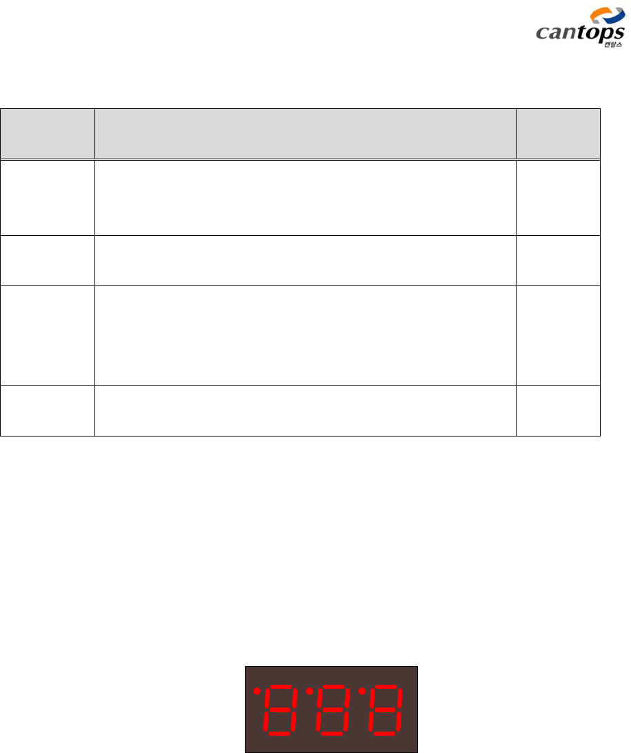
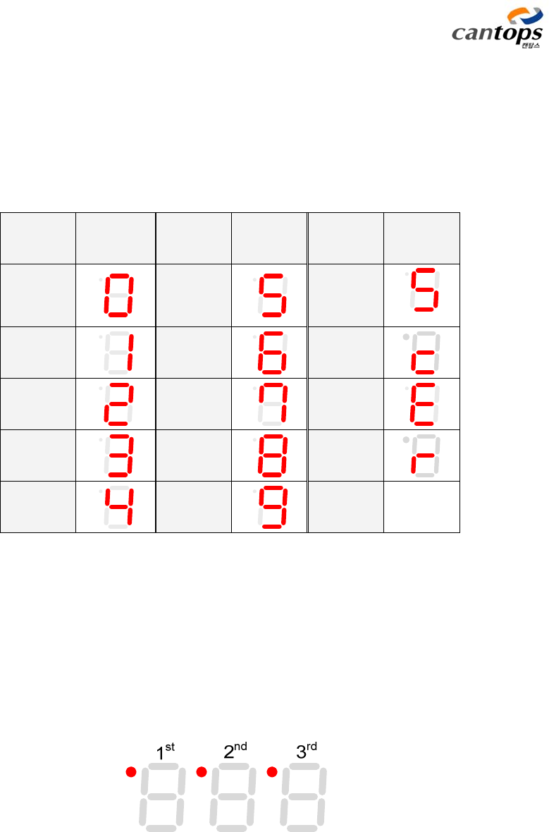
b) 7 Segment section
This is used for indicating the operation state of reader and individual numbers (ID) of reader
and antenna, and displaying the state of noise level, antenna output tuning value, and so forth
with numerals. The segment is constituted with 3-digit, and a diversity of states are indicated for
each of the modes.
<Fig. 10> 3 Digit 7 Segment
CTS-STBR-AA
13
Those numerals and characters indicated through 7 Segment are as shown in the following
<Table 6>.
<Table 6> Details of numeral and character indication with 7 Segment
Indicated
numeral
Indicated
contents
Indicated
numeral
Indicated
contents
Indicated
character
Indicated
contents
0
5
S
1
6 c
2
7 E
3
8 r
4
9
The red dot at the top left side of Segment in <Fig. 10> displays a variety of indications at
each of the modes. The dot at the first segment is lighted when the command inputted
through EtherCAT communication or button is performed, and the dot at the second segment
is lighted when the Sensor2(HOME Sensor) input is ON, and the dot at the third segment is
lighted when the Sensor1(FOUP Sensor) input is ON. In addition, from the ID setup mode, the
location of digit number to be set up is indicated.
<Fig. 11> Dot indication of 7 Segment
CTS-STBR-AA
14
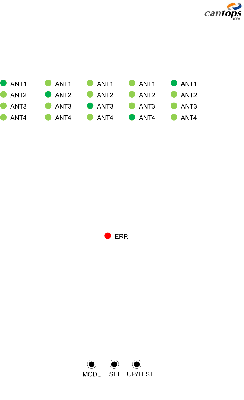
c) LED for indicating antenna channel
The antenna under operation is indicated with 4 LEDs. For selecting antenna, if pressing SEL
switch, corresponding antenna will sequentially (from No. 1 to No. 4) be selected.
=> => => => => Repetition
=>
<Fig. 12> LED for indicating antenna channel
d) LED for indicating error
When error is occurred under the operation of reading or writing the tag, the error LED is
lighted. Error state is remembered by the reader inside for each channel, and even when the
selection of antenna is changed, the latest error state is indicated at LED.
<Fig. 13> LED for indicating error
e) Switch for manual operation
There are 3 switches for manual operation, and each of their functions is as shown in the
following <Table 7>.
<Fig. 14> Manual operation switch

CTS-STBR-AA
15
<Table 7> Function of switch
Name of
switch
Function Remarks
MODE
When this button is pressed, 3 types of setup modes (TUNE, SENS,
ID) can sequentially be selected. If the function of reading and
writing data on the tag is to be used, press the MODE switch so
that RDY LED is lighted.
SEL
This is the button of selecting antenna channel. When pressing this
button, the antennas of 4 channels can sequentially be selected.
Whenever pressing the button, the antenna to be used will be
selected in the order of the number 1 -> 2 -> 3 -> 4.
UP/TEST
① RDY mode: Whenever pressing this button with the function of
manually reading the data in the tag, the tag data is read once a
time. When this switch is pressed for the duration of more than 1
second, continuous reading mode is operated. If it is wanted to get
out of this continuous reading mode, simply press this button once
more. This action can be operated only under the turning on state
of READY LED which is not a setup mode.
② TUNE mode: When the tuning mode is activated, this is used in
the same way as that of general enter key.
③ SENS mode: No operation is conducted.
④ ID setup mode: This is used as the function of increasing the
number indicated at the 7 Segment one by one. When this switch is
pressed with the duration of more than 1 second, it will be used as
the function of changing the digit to be set up. The digit is changed
in the order of single-digit -> double-digit -> three-digit.
Read Page = 15
CTS-STBR-AA
16
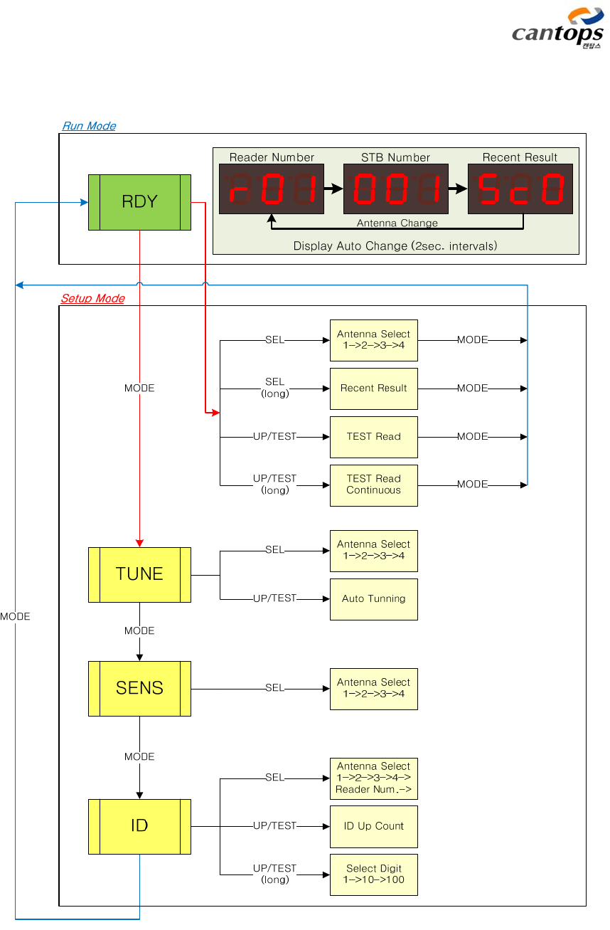
f) Sequence diagram of panel operation
<Fig. 15> Sequence diagram of panel operation
CTS-STBR-AA
17
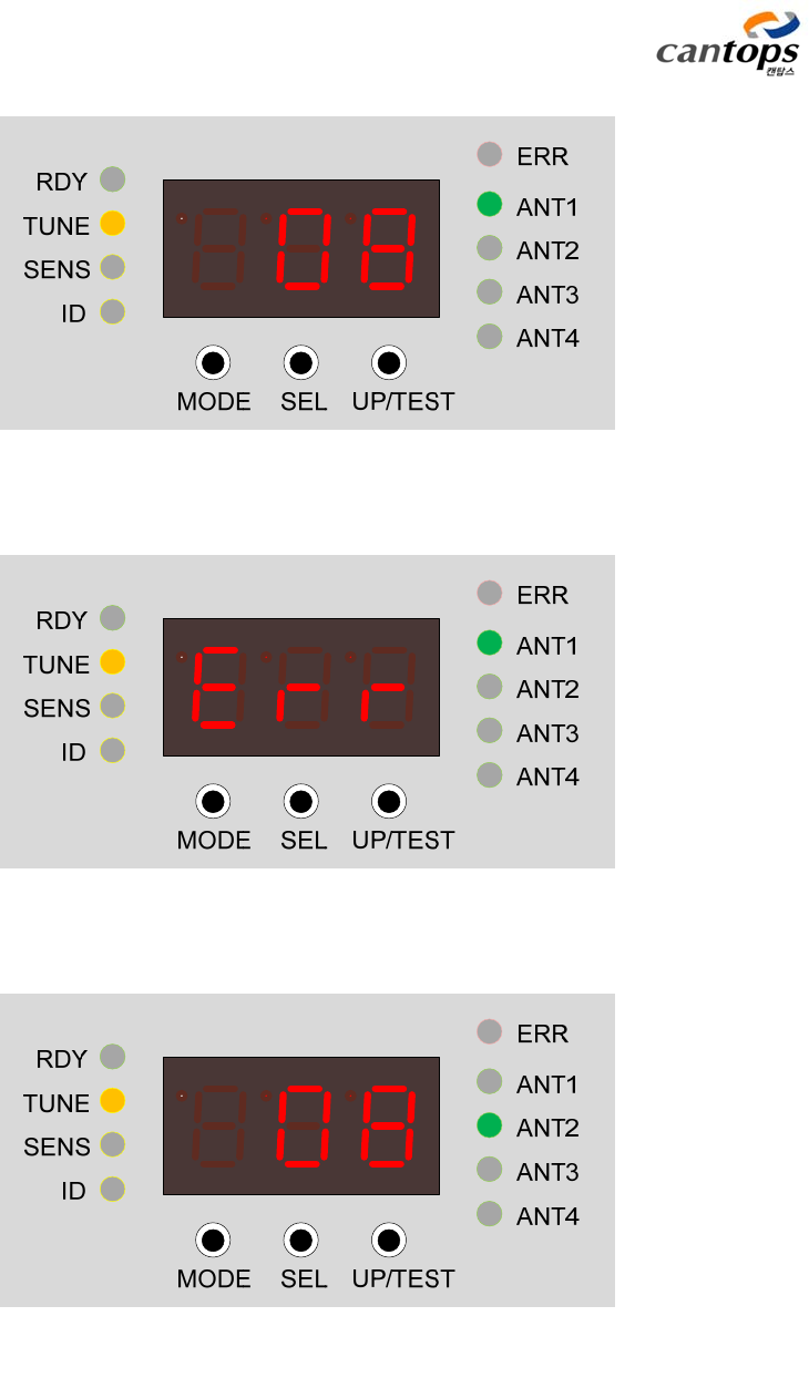
g) Description of panel operation
ⓐ RDY MODE
This is the function for testing the reading of the tag data by the reader independently
without high rank host. It can simply be activated by pressing the UP/TEST switch under the
turning on state of RDY LED after coming out of setup mode with the MODE switch. With this
mode, the data in the page 15 of the tag will be read.
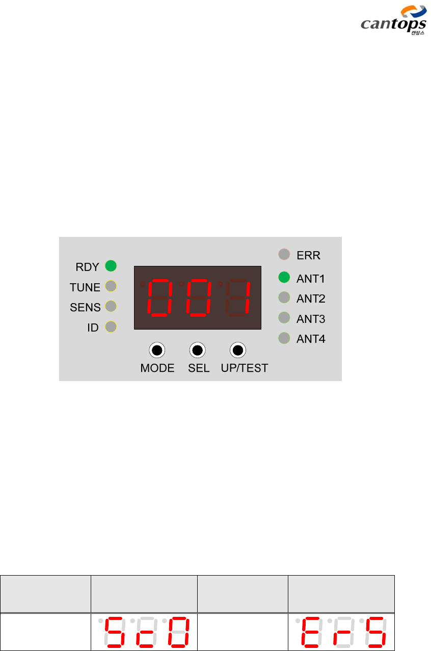
<Fig. 16> Indicating state of RDY MODE
When the test of manually reading the tag from the reader is conducted, Er(Reading failed)
and Sc(Reading succeeded) are indicated through the indication window as shown in <Table 8>.
In the third digit of the Segment, the number of re-attempted reading is indicated in the case of
succeeded reading, and error code is indicated in the case of failed reading.
<Table 8> Contents of state indication during the reading operation of tag
State Contents of
indication
State Contents of
indication
Sc(No error) Er(Error is
generated)
The error codes at the time of failed reading are as shown in the following <Table 9>.

CTS-STBR-AA
18
<Table 9> Type of error code
Code State Remarks
‘4’ When writing the data on the tag is failed
‘5’ When there is no tag
‘6’ When the type of tag is different from that of the received
command
‘7’ When the check sum error is generated from the tag
‘8’ Communication error with the tag
‘9’ When there is no antenna or when problem is occurred for
installing the antenna
ⓑ TUNE MODE
Basic principle of RFID is to transmit and receive data in accordance with mutually decided
agreement after supplying power to the Tag(Transponder) by producing high voltage signal
from antenna. This high voltage signal is created by the LC resonance from the oscillation circuit
of antenna and reader inside, and, in general, the higher this oscillated voltage becomes, the
lengthier will be the reading distance.
This TUNE(Tx Tuning) mode is the function of tuning internal circuit in such a way that
transmitting voltage of antenna becomes the highest one. This is the function to be conducted
in the first place in order to have a stable operation after installing the reader.
Setup value is indicated at the 7 Segment, and it will be adjusted to 16 steps from 00 to 15.
<Fig. 17> is the initial indication state under the TUNE mode. In the initial state, currently set
up tuning value is displayed. When UP/TEST button is pressed, tuning is started. It takes around
1 second for the tuning, and when the tuning is finished, a new setup value is indicated at the
7 Segment. This value is automatically saved and used internally, therefore, a separate recording
is not required.
If antenna is not connected or if there is problem for the wiring of antenna, measuring value
of transmitting voltage may become too low during the Tx Tuning. In this case, the resultant
value after the tuning is not applied, and the previous setup value will be maintained as it is. In
the 7 Segment, ‘Err’ is indicated as shown in <Fig. 18>. In this circumstances, Tx Tuning shall be
attempted again after confirming the connecting state of antenna. When SEL button is pressed
to change the channel of antenna, each of the antennas can be selected in the order of ANT1 -
> ANT2 -> ANT3 -> ANT4. The case of selecting No. 2 antenna is shown in <Fig. 19>.
CTS-STBR-AA
19
<Fig. 17> Indicating state of TUNE MODE
<Fig. 18> Indication of tuning error state
<Fig. 19> Indication of ANT2 state
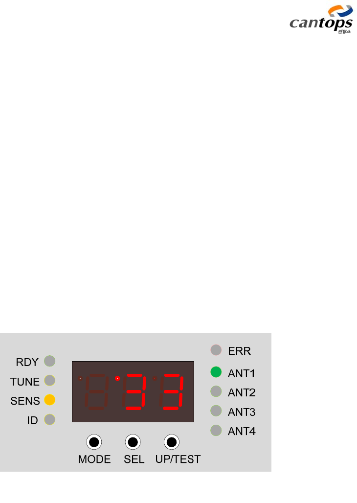
ⓒ SENS MODE
In the case of RFID, communication between Tag and antenna is conducted by using the
CTS-STBR-AA
20
frequency of around 130KHz. This frequency of around 130KHz is the electromagnetic wave which
can generally be created during the switching of semiconductor for motor or power. Therefore,
under the deteriorated environment with this kind of switching element, normal operation of RFID
is difficult to expect. This SENS(Rx Sensitivity) mode is the function of indicating the strength of
noise around the frequency of 130KHz. With this function, the antenna can be installed at the
location without noise, and the noise level can directly be confirmed when corrective measures
are prepared for other appliances, therefore, it is a convenient function of rapidly providing the
optimum measures.
<Fig. 20> is the example of indicating the operation state of this mode, and the indicated
value is 00 ~ 99, and the lower value indicates the state of not having the noise. Therefore, please
set up the surronding environment so that the value ouputted from the 7 Segment becomes “00”
as much as possible. Especially, when this value becomes more than “70”, the reading
performance may be dropped by external noise, therefore, a sufficient corrective measures shall
be established.
When entering to SENS mode, Rx Sensitivity action is started, and the noise level will
continously be indicated at the 7 Segment as shown in <Fig. 20>.
<Fig. 20> Operation result of SENS MODE
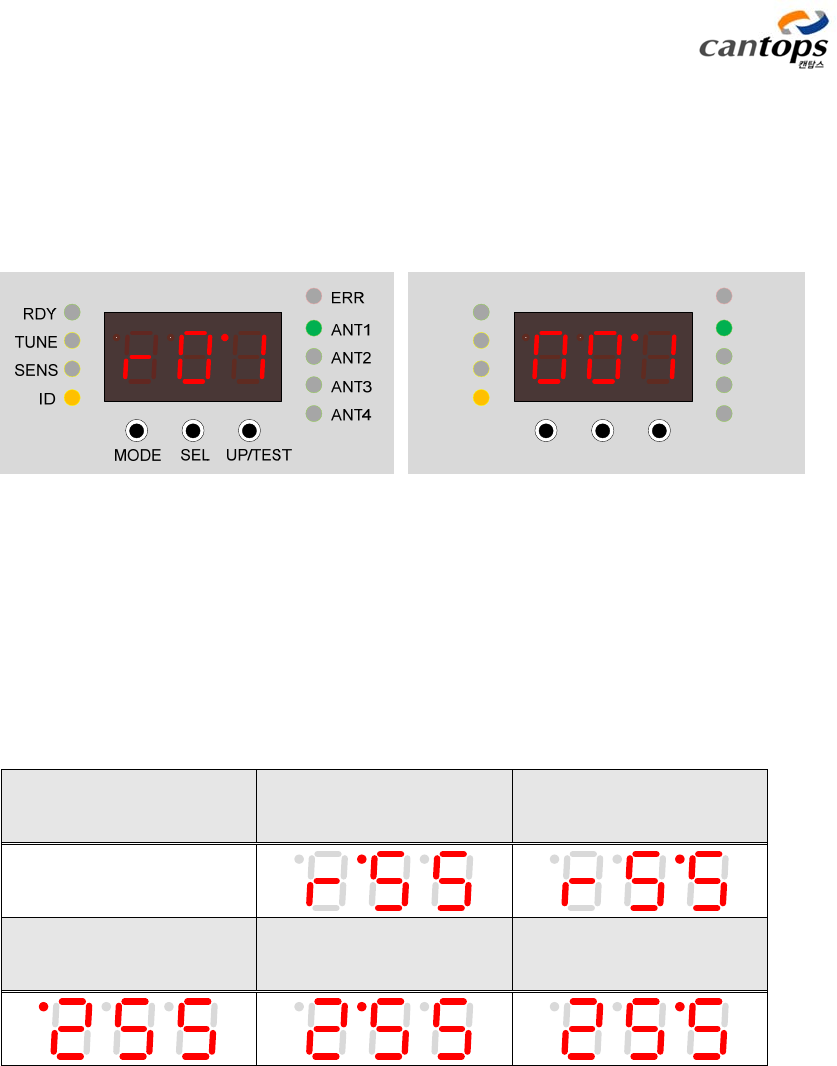
ⓓ ID MODE
This is the function of setting up the individual number of the reader, and 1 reader number
and 4 STB (antenna) numbers can be set up. For the reader number, 64 numbers can be set up in
the range of r01 ~ r64, and for the STB (antenna) number, 255 IDs can be set up in the range of
001 ~ 255. Basic setup value is “r00” and “000”, respectively, and the reader set up as “000”
becomes a disabled state in which no operation is conducted. Cares shall be taken not to have
CTS-STBR-AA
21
the identical ID.
When UP/TEST button is pressed under ID setup mode, the number of selected digit will be
increased one by one. When UP/TEST button is pressed with the duration of more than 1 second,
it is used as the function of changing the digit to be set up. The digit is changed in the order of
single-digit -> double-digit -> three-digit.
RDY
TUNE
SENS
ID
MODE SEL UP/TEST
ERR
ANT1
ANT2
ANT3
ANT4
<Fig. 21> Indicating state of reader number (left) and STB number (right)
of ID MODE
<Table 10> Indication of ID setup digit state
Setting up the second
digit of the Reader
Setting up the first digit
of the Reader
Setting up the third digit
of STB
Setting up the second
digit of STB
Setting up the first digit
of STB
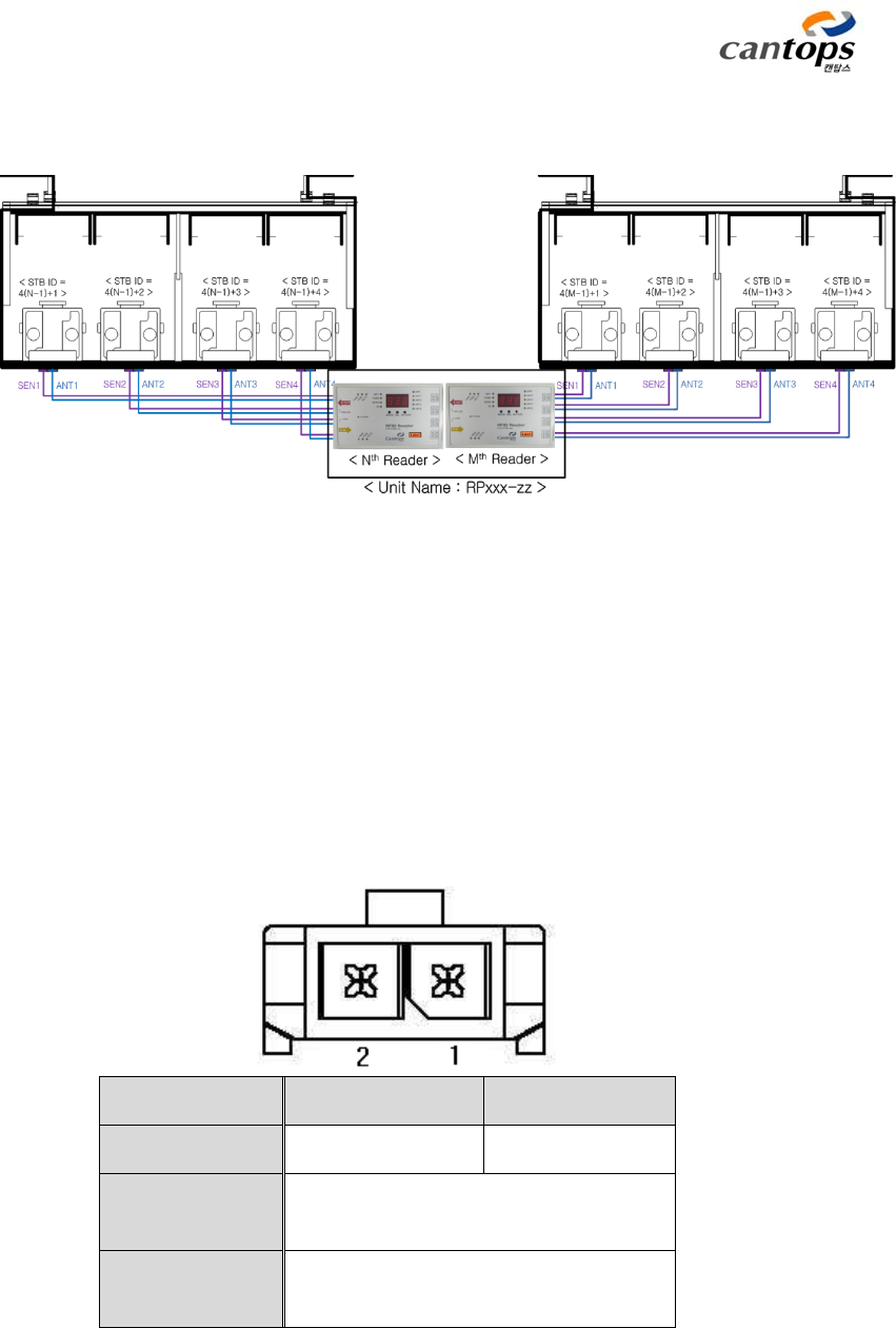
2.5 Antenna and sensor linking connector
From this reader, maximum 4 antennas and sensor can be connected as shown in <Fig.
22>. The occasions that reading work is conducted by RFID reader are the unit reading
command through EtherCAT communication, the Verify command which confirms the state of
FOUP and tag data, the function of automatic reading at the time when the FOUP sensor
becomes changed from Off to On, and the reading function under the manual operation
mode. In this way, except manual mode and simple reading command, operation is always
CTS-STBR-AA
22
conducted in connection with FOUP sensor in actual operation environment, therefore, it shall
always be operated with the same number.
<Fig. 22> Example of using antenna and sensor
The antenna and sensor cable provided by this company are supposed to be linked to this
connector, and separation and connection of antenna and sensor cable shall always be conducted
under turned off or disabled state of power.
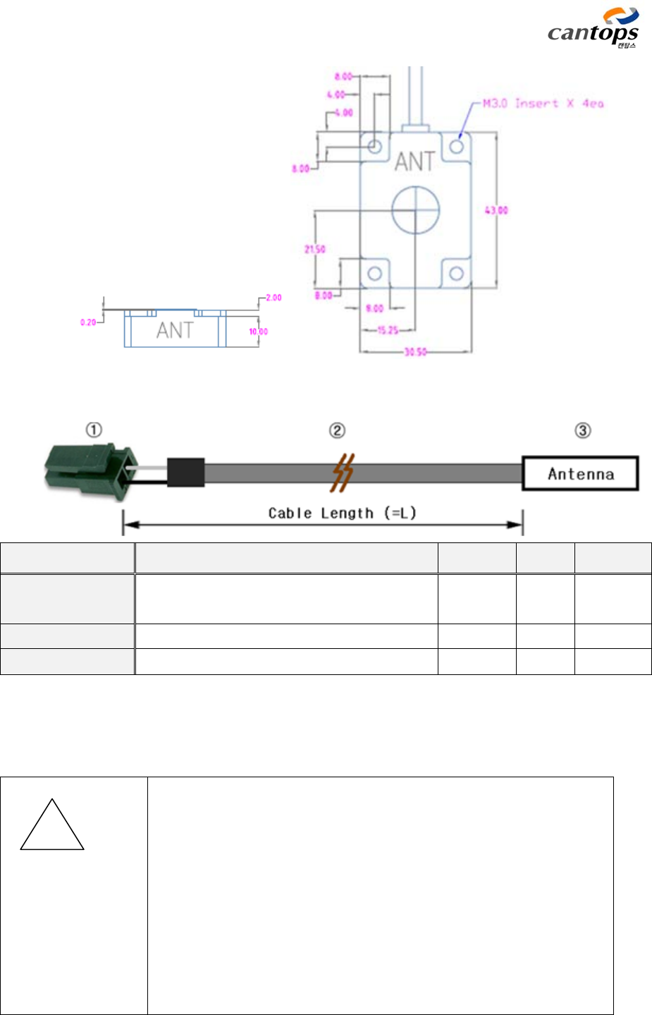
This antenna is the one made in such a way that it can have the reading by attaching to the
plate such as STB which saves FOUP, or UTB, etc. When special products such as different shape
or reading performance, cable length, and so forth are required, please contact with this company.
<Fig. 23> Arrangement of antenna connector pin
Pin number 1 2
Function ANT+ ANT-
Name of
connector 43650-0200, Molex
Connector for
cable 42645-0200, Molex
CTS-STBR-AA
23
<Fig. 24> Size of antenna head section
Description Specification Maker Q`ty Remark
① Connector Housing : 42645-0200
Terminal : 43030-0002 Molex 1EA
2EA
② Cable AWG#22, 1 strand, Shield, UL1185, Grey CanTops 1EA
③ Antenna head 43x30.5x12mm, Polycarbonate, black CanTops 1EA
<Fig. 25> Constitution of antenna cable
☞ As high voltage is being flown in this antenna connector, do not
touch it because there is the danger of electric shock when it is
touched. Attaching and detaching the cable during the operation
of the reader is extremely dangerous. Connecting and separating
work of cable shall always be conducted under the turned off state
of electric power.
☞ Only the cable manufactured by this company shall be used as the
antenna cable, and when the extenstion of cable is unavoidable,
taked care that all wires shall not touch external appliances,
! Caution
CTS-STBR-AA
24
grounding wire, etc.
☞ Conductor, cable, and so forth shall be away from the vicinity of
antenna head as much as possible. Otherwise, reading
performance can be deteriorated.
☞ The shapes of antenna and sensor are the same with each other,
therefore, cares shall be taken to have wiring of antenna and
sensor to the same number during the installation.
☞ When antenna is installed for the first time or when surrounding
circumstances are changed, a new tuning shall definitely be
conducted in order to have the optimum operating condition for
the reader.
Connecting specification and configuration diagram of the sensors which detect the state of
FOUP are as shown in the following Figure. Pin numbers are based on the view from the
connector actually installed in the board. Basically, 2 sensors can be interlocked with 1 antenna,
however, basic operation is conducted with 1 FOUP sensor. Additional sensor can be used by
connecting with general sensor other than FOUP detecting sensor. Check IN1 & 2 are the signals
outputted from the reader for checking in advance the change of sensitivity and life of sensors.
With this function, abnormality of the function related with the sensitivity of sensors installed at
the entire line can systematically be managed.
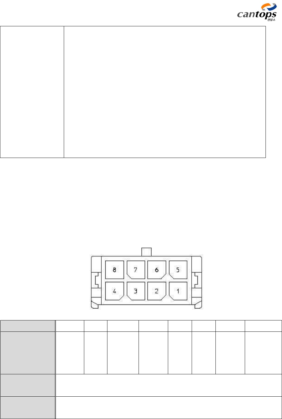
<Fig. 26> Arrangement of sensor connector pin
Pin number 1 2 3 4 5 6 7 8
Function +24V GND
Sensor
OUT1
(FOUP
Sensor)
Check
IN1 +24V GND
Sensor
OUT2
(Home
Sensor)
Check
IN2
Name of
connector 43045-0800, Molex
Connector for
cable 43025-0800, Molex
CTS-STBR-AA
25
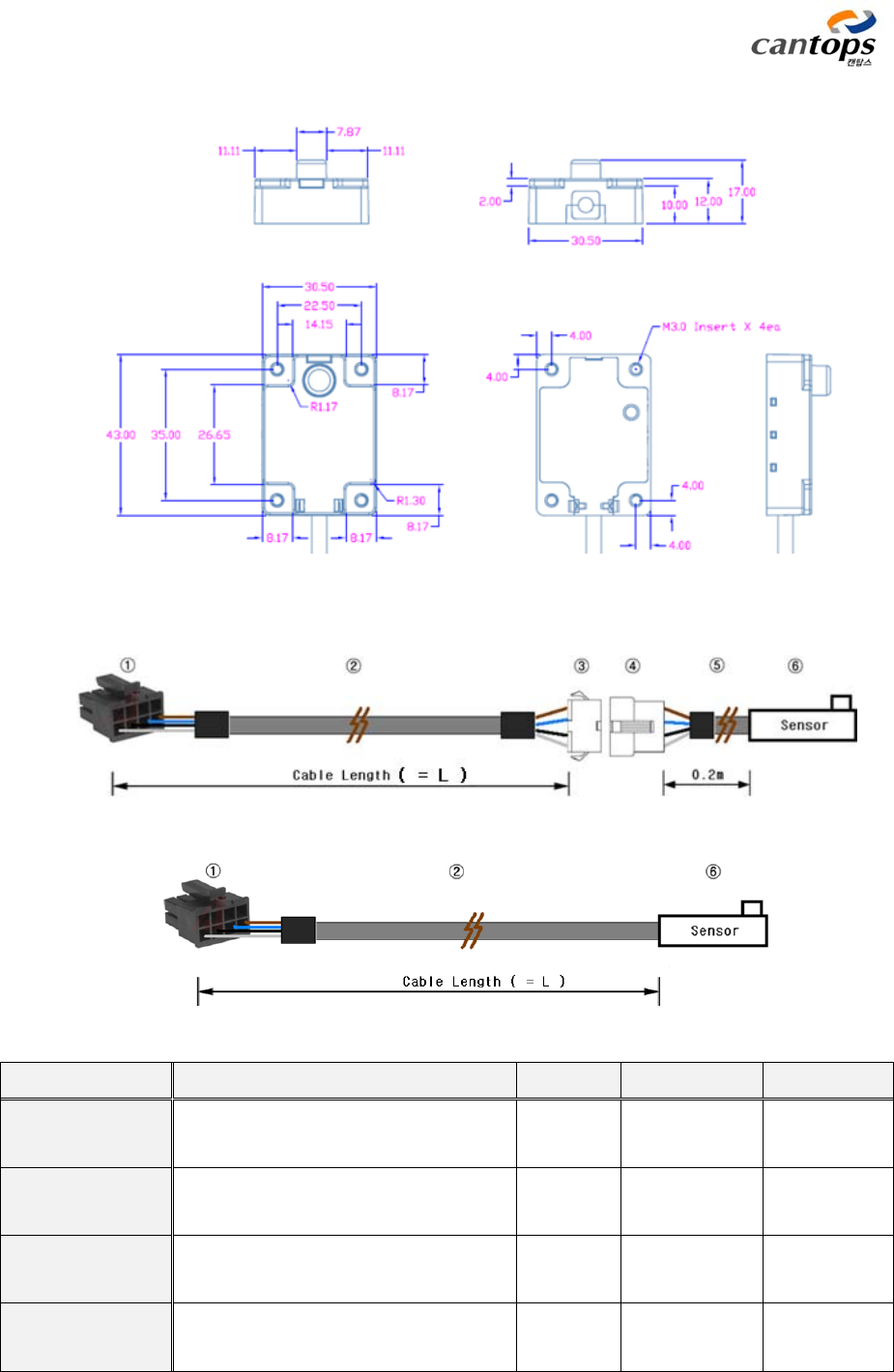
<Fig. 27> Size of sensor head section
(a) Head separation type
(b) Head integration type
Description Specification Maker Q`ty Remark
① Housing Housing : 43025-0800
Terminal : 43030-0001 Molex 1EA
4EA
② Cable 4C X 24AWG, UL2464 Gwangil
Electric L
③ Housing SMP-04V-NC, 4 Pin, Plug(Socket)
SHF-001T-0.8BS JST 1EA
4EA
④ Housing SMR-04V-N, 4 Pin, Receptacle(Pin)
SYM-001T-P0.6 JST 1EA
4EA

CTS-STBR-AA
26
<Fig. 28> Constitution of sensor cable
When FOUP sensor is operated in actual using environment, there is an unstable period in
which signal becomes On/Off in the transient state. This unstable time of signal can be set up as
the time constant of filter. For detailed information, refer to the setup parameter.
☞ Optical type sensor is used at the FOUP detecting sensor inside.
Therefore, when particles are flown in from outside, abnormality of
FOUP detection can be occurred because sensitivity of sensor is
deteriorated. Periodic inspection of sensor state is required.
⑤ Cable 4C X 24AWG, UL2464 Gwangil
Electric 0.2m
⑥ Sensor Head Main body of sensor CanTops 1EA
! Caution
CTS-STBR-AA
27
3. EtherCAT connection and communication specification
3.1 Connecting method of EtherCAT
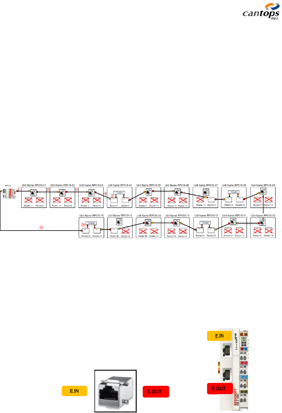
Although it is different in accordance with the configuration of system, readers, in general, are
not installed once and for all, but extension is conducted during the line expansion. However, in
the case of basic infrastructure required such as overall network, power lines, and so forth, it
can be efficient to install them during the initial investment. The following <Fig. 29> is the
example of connecting only 10 units after constituting the network so that maximum 32 units of
readers can be connected. Maximum 64 units of readers can be connected to one EtherCAT
Master, and in the case of antenna, up to the total 255 units can be used.
As the number of the reader connected to EtherCAT Master, a serial number is given and this
serial number is also applied to the number of the antenna connected to the reader. For the
antenna which is not used, No. 0 can simply be designated. In the case of the nth reader, the ID
numbers of 4(n-1)+1, 4(n-1)+2, 4(n-1)+3, and 4(n-1)+4 can be designated.
<Fig. 29> Example of EtherCAT wiring
2 readers are installed in a unit, and for the sake of this expansibility, communication line is
connected with RJ45 Coupler or EtherCAT Coupler as shown in <Fig. 30>. In general, LAN line is
connected with RJ45 coupler, and when more than 3 units of this coupler are to be used,
EtherCAT Coupler shall always be installed. Once a coupler is installed, it shall always be
remained at the fixed location.
CTS-STBR-AA
28
(a) RJ45 Coupler (b) EtherCAT Coupler
<Fig. 30> Type of coupler
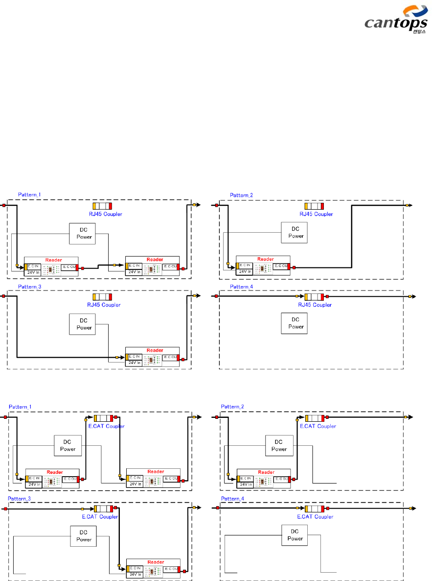
The method of wiring the LAN line in accordance with the existence and nonexistence of
reader is as shown in <Fig. 31>. When the reader is to be installed in the unit where RJ45
Coupler is used, RJ45 Coupler will not be used. In the structure where EtherCAT Coupler has
been used, the wiring shall always be conducted with the structure of using EtherCAT Coupler.
(a) Internal wiring diagram of the unit constituted with RJ45 Coupler
(b) Internal wiring diagram of the unit constituted with EtherCAT Coupler
<Fig. 31> Internal wiring diagram of the unit considering expansibility in
the future

CTS-STBR-AA
29
3.2
Structure of EtherCAT communication
The structure of transmitting and receiving data between EtherCAT Master and Slave(Reader) is
to have the communication in real time by loading the data packet for EtherCAT on the basic
Ethernet communication frame as shown in <Fig. 32>. From this reader (Slave), data is renewed
with the cycle of 10ms, and maximum 255 units of antenna can be used.
통신 주기 Communication cycle
<Fig. 32> EtherCAT communication flow
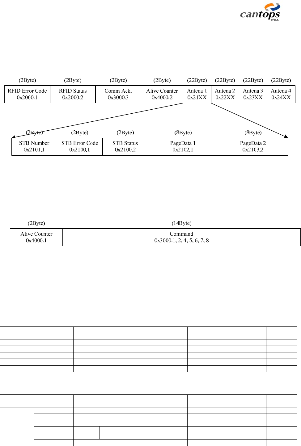
In order to transmit cyclical data in real time, PDO(Process Data Objects) which is a cyclic data is
CTS-STBR-AA
30
to be used. PDO data format of this reader is as shown in the following <Fig. 33>.
TxPDO (96Byte) : Slave -> Master
RxPDO (18Byte) : Master -> Slave
<Fig. 33> Configuration of PDO data
3.3 PDO map list
System Parameters
Inde
x
Su
b
Index
Siz
e
Nam
e
RWRang
e
Defaul
t
Refe
r
0x1000 4 Device Type RO 0x00001389
0x1001 2 Error Register RO 0x0000
0x1008 2 Device Name RO 0x0001
0x1009 2 Hardware
V
ersion RO 0x0013 *1
0x100A 2 Software
V
ersion RO 0x0012 *1
RFID Reader Parameters
Inde
x
Su
b
Index
Siz
e
Nam
e
RWRang
e
Defaul
t
Refe
r
0x2000
RFID
Error and
Status
0
2
Sub Index Number
1 2 RFID Reader Error Code RO 0x0000 ~
0x00ff
0x0000
LSB RFID Error Code RO *2
MSB RO
2 2 RFID Reader Status RO 0x0000 ~ 0x0000

CTS-STBR-AA
31
0xffff
0 RFID Reader Ready RO 0 ~ 1 0 Ready=1
1 Reserved RO 0 ~ 1 0
2 Reserved RO 0 ~ 1 0
3 E.CAT IN Connect RO 0 ~ 1 0 Connect=
1
4 E.CAT OUT Connect RO 0 ~ 1 0 Connect=
1
5 Reserved RO 0 ~ 1 0
6 Firmware Download Status RO 0 ~ 1 1 *3
7 Command Done Flag RO 0 ~ 1 1 *4
8 Reserved RO 0 ~ 1 0
9 Reserved RO 0 ~ 1 0
10 Reserved RO 0 ~ 1 0
11 Reserved RO 0 ~ 1 0
12 Reserved RO 0 ~ 1 0
13 Reserved RO 0 ~ 1 0
14 Reserved RO 0 ~ 1 0
15 Reserved RO 0 ~ 1 0
0x2001
RFID
Parameter
0
2
Sub Index Number
1 2 RFID Reader ID RW 1 ~ 64 0
2 2 UART Baud rate RW 0 ~ 5 5 5=115200
3 2 Tx Duty RW 0 ~ 99 50 (%)
4 2 Tx Start Duty RW 0 ~ 99 50 (%)
5 2 Tx Start Time RW 0 ~ 255 100 (us)
6 2 Charge Time RW 20 ~ 255 60 (ms)
7 2 Rx Sensitivity Low Voltage RW 0 ~ 30 8 (0.1V)
8 2 Rx Sensitivity High Voltage RW 0 ~ 30 20 (0.1V)
9 2 Rx Sensitivity Time Delay RW 0 ~ 65535 200 (ms)
10 2 Read Retry Count RW 1 ~ 10 3 (time)
11 2 Read Retry Interval RW 0 ~ 255 100 (ms)
12 2 Read Start Delay RO 0 ~ 65535 *5
13 2 Test Read Page RW 1 ~ 17 15 (page)
14 2 Test Read Inter
v
al RW 0 ~ 65535 1000 (ms)
15 2 HRE Clear Time RW 0 ~ 999 30 (s)
16 2 Reserved
17 2 Reserved
18 2 Reserved
19 2 Reserved
20 2 Reserved
0x2002
Index Of
Page Data
0
2
Sub Index Number
1 2 Index Of PageData1 RW 1~17 1 0xFF=auto
2 2 Index Of PageData2 RW 1~17 2 0xFF=auto
3 2 Index Of PageData3 RW 1~17 0
4 2 Index Of PageData4 RW 1~17 0
5 2 Index Of PageData5 RW 1~17 0
6 2 Index Of PageData6 RW 1~17 0
7 2 Index Of PageData7 RW 1~17 0
8 2 Index Of PageData8 RW 1~17 0
Antenna1 (STB) Parameters
Inde
x
Su
b
Index
Siz
e
Nam
e
RWRang
e
Defaul
t
Refe
r
0x2100
ANT1
Error and
Status
0
2
Sub Index Number
1 2 STB Error Code RO
LSB STBC Error Code RO 0x0000 ~
0x00ff
0x0000 *6
MSB ANT Error Code RO 0x0000 ~
0xff00
0x0000 *7
2 2 STB Status RO
0 STB Ready RO 0 ~ 1 0 Ready=1
1 Carrier Sensor State (Foup) RO 0 ~ 1 0 ON=1
2 Home Sensor State (HP) RO 0 ~ 1 0 ON=1

CTS-STBR-AA
32
3 E.CAT IN Connect RO 0 ~ 1 0 Connect=
1
4 E.CAT OUT Connect RO 0 ~ 1 0 Connect=
1
5 Tag Read Complete RO 0 ~ 1 0 Detect=1
6 Home Rising Edge RO 0 ~ 1 1 Detect=1
7 Reserved
8 STB Enable RO 0 ~ 1 0 Enable=1
9 Carrier Sensor Diagnosis RO 0 ~ 1 1 Normal=1
10 Home Sensor Diagnosis RO 0 ~ 1 1 Normal=1
11 Tx Power Diagnosis RO 0 ~ 1 1 Normal=1
12 Noise Sens Diagnosis RO 0 ~ 1 1 Normal=1
13 Sensor1 Enabled RO 0 ~ 1 0 Enable=1
14 Page Data Info. RO 0 ~ 1 0 *8
15 Sensor2 Enabled RO 0 ~ 1 0 Enable=1
0x2101
ANT1
Parameter
0
2
Sub Index Number
1 2 STB Number RW 0 ~ 255 0 *9
2 2 Tx Tuning Level RW 0 ~ 15 8
3 2 Tx Power RO 0 ~ 65535 0 (V)
4 2 Tx Power Diag Threshold RW 0 ~ 65535 100 (V)
5 2 Noise Sensitivity RO 0 ~ 99 0 (%)
6 2 Noise Sens Diag Threshold RW 0 ~ 99 90 (%)
7 2 Sensor1 Enable (Foup/Carrier) RW 0 ~ 1 1
8 2 Sensor1 Polarity (Foup/Carrier) RW 0 ~ 1 1
9 2 Sensor1 Filter Order (Foup/Carrier) RW 1 ~ 31 10(200ms) (20ms)
10 2 Sensor2 Enable (Home/HP) RW 0 ~ 1 0
11 2 Sensor2 Polarity (Home/HP) RW 0 ~ 1 1
12 2 Sensor2 Filter Order (Home/HP) RW 1 ~ 31 10(200ms) (20ms)
13 2 Reserved
14 2 Reserved
15 2 Reserved
16 2 Reserved
0x2102
ANT1
Page Data
0
2
Sub Index Number
1 8 PageData1 RO
2 8 PageData2 RO
3 8 PageData3 RO
4 8 PageData4 RO
5 8 PageData5 RO
6 8 PageData6 RO
7 8 PageData7 RO
8 8 PageData8 RO
Antenna2 (STB) Parameters
Inde
x
Su
b
Index
Siz
e
Nam
e
RWRang
e
Defaul
t
Refe
r
0x2200
ANT2
Error and
Status
0
2
Sub Index Number
1 2 STB Error Code RO
LSB STBC Error Code RO 0x0000 ~
0x00ff
0x0000 *6
MSB ANT Error Code RO 0x0000 ~
0xff00
0x0000 *7
2 2 STB Status RO
0 STB Ready RO 0 ~ 1 0 Ready=1
1 Carrier Sensor State (Foup) RO 0 ~ 1 0 ON=1
2 Home Sensor State (HP) RO 0 ~ 1 0 ON=1
3 E.CAT IN Connect RO 0 ~ 1 0 Connect=
1
4 E.CAT OUT Connect RO 0 ~ 1 0 Connect=
1
5 Tag Read Complete RO 0 ~ 1 0 Detect=1
6 Home Rising Edge RO 0 ~ 1 1 Detect=1
7 Reserved

CTS-STBR-AA
33
8 STB Enable RO 0 ~ 1 0 Enable=1
9 Carrier Sensor Diagnosis RO 0 ~ 1 1 Normal=1
10 Home Sensor Diagnosis RO 0 ~ 1 1 Normal=1
11 Tx Power Diagnosis RO 0 ~ 1 1 Normal=1
12 Noise Sens Diagnosis RO 0 ~ 1 1 Normal=1
13 Sensor1 Enabled RO 0 ~ 1 0 Enable=1
14 Page Data Info. RO 0 ~ 1 0 *8
15 Sensor2 Enabled RO 0 ~ 1 0 Enable=1
0x2201
ANT2
Parameter
0
2
Sub Index Number
1 2 STB Number RW 0 ~ 255 0 *9
2 2 Tx Tuning Level RW 0 ~ 15 8
3 2 Tx Power RO 0 ~ 65535 0 (V)
4 2 Tx Power Diag Threshold RW 0 ~ 65535 100 (V)
5 2 Noise Sensitivity RO 0 ~ 99 0 (%)
6 2 Noise Sens Diag Threshold RW 0 ~ 99 90 (%)
7 2 Sensor1 Enable (Foup/Carrier) RW 0 ~ 1 1
8 2 Sensor1 Polarity (Foup/Carrier) RW 0 ~ 1 1
9 2 Sensor1 Filter Order (Foup/Carrier) RW 1 ~ 31 10(200ms) (20ms)
10 2 Sensor2 Enable (Home/HP) RW 0 ~ 1 0
11 2 Sensor2 Polarity (Home/HP) RW 0 ~ 1 1
12 2 Sensor2 Filter Order (Home/HP) RW 1 ~ 31 10(200ms) (20ms)
13 2 Reserved
14 2 Reserved
15 2 Reserved
16 2 Reserved
0x2202
ANT2
Page Data
0
2
Sub Index Number
1 8 PageData1 RO
2 8 PageData2 RO
3 8 PageData3 RO
4 8 PageData4 RO
5 8 PageData5 RO
6 8 PageData6 RO
7 8 PageData7 RO
8 8 PageData8 RO
Antenna3 (STB) Parameters
Inde
x
Su
b
Index
Siz
e
Nam
e
RWRang
e
Defaul
t
Refe
r
0x2300
ANT3
Error and
Status
0
2
Sub Index Number
1 2 STB Error Code RO
LSB STBC Error Code RO 0x0000 ~
0x00ff
0x0000 *6
MSB ANT Error Code RO 0x0000 ~
0xff00
0x0000 *7
2 2 STB Status RO
0 STB Ready RO 0 ~ 1 0 Ready=1
1 Carrier Sensor State (Foup) RO 0 ~ 1 0 ON=1
2 Home Sensor State (HP) RO 0 ~ 1 0 ON=1
3 E.CAT IN Connect RO 0 ~ 1 0 Connect=
1
4 E.CAT OUT Connect RO 0 ~ 1 0 Connect=
1
5 Tag Read Complete RO 0 ~ 1 0 Detect=1
6 Home Rising Edge RO 0 ~ 1 1 Detect=1
7 Reserved
8 STB Enable RO 0 ~ 1 0 Enable=1
9 Carrier Sensor Diagnosis RO 0 ~ 1 1 Normal=1
10 Home Sensor Diagnosis RO 0 ~ 1 1 Normal=1
11 Tx Power Diagnosis RO 0 ~ 1 1 Normal=1
12 Noise Sens Diagnosis RO 0 ~ 1 1 Normal=1
13 Sensor1 Enabled RO 0 ~ 1 0 Enable=1
14 Page Data Info. RO 0 ~ 1 0 *8

CTS-STBR-AA
34
15 Sensor2 Enabled RO 0 ~ 1 0 Enable=1
0x2301
ANT3
Parameter
0
2
Sub Index Number
1 2 STB Number RW 0 ~ 255 0 *9
2 2 Tx Tuning Level RW 0 ~ 15 8
3 2 Tx Power RO 0 ~ 65535 0 (V)
4 2 Tx Power Diag Threshold RW 0 ~ 65535 100 (V)
5 2 Noise Sensitivity RO 0 ~ 99 0 (%)
6 2 Noise Sens Diag Threshold RW 0 ~ 99 90 (%)
7 2 Sensor1 Enable (Foup/Carrier) RW 0 ~ 1 1
8 2 Sensor1 Polarity (Foup/Carrier) RW 0 ~ 1 1
9 2 Sensor1 Filter Order (Foup/Carrier) RW 1 ~ 31 10(200ms) (20ms)
10 2 Sensor2 Enable (Home/HP) RW 0 ~ 1 0
11 2 Sensor2 Polarity (Home/HP) RW 0 ~ 1 1
12 2 Sensor2 Filter Order (Home/HP) RW 1 ~ 31 10(200ms) (20ms)
13 2 Reserved
14 2 Reserved
15 2 Reserved
16 2 Reserved
0x2302
ANT3
Page Data
0
2
Sub Index Number
1 8 PageData1 RO
2 8 PageData2 RO
3 8 PageData3 RO
4 8 PageData4 RO
5 8 PageData5 RO
6 8 PageData6 RO
7 8 PageData7 RO
8 8 PageData8 RO
Antenna4 (STB) Parameters
Inde
x
Su
b
Index
Siz
e
Nam
e
RWRang
e
Defaul
t
Refe
r
0x2400
ANT4
Error and
Status
0
2
Sub Index Number
1 2 STB Error Code RO
LSB STBC Error Code RO 0x0000 ~
0x00ff
0x0000 *6
MSB ANT Error Code RO 0x0000 ~
0xff00
0x0000 *7
2 2 STB Status RO
0 STB Ready RO 0 ~ 1 0 Ready=1
1 Carrier Sensor State (Foup) RO 0 ~ 1 0 ON=1
2 Home Sensor State (HP) RO 0 ~ 1 0 ON=1
3 E.CAT IN Connect RO 0 ~ 1 0 Connect=
1
4 E.CAT OUT Connect RO 0 ~ 1 0 Connect=
1
5 Tag Read Complete RO 0 ~ 1 0 Detect=1
6 Home Rising Edge RO 0 ~ 1 1 Detect=1
7 Reserved
8 STB Enable RO 0 ~ 1 0 Enable=1
9 Carrier Sensor Diagnosis RO 0 ~ 1 1 Normal=1
10 Home Sensor Diagnosis RO 0 ~ 1 1 Normal=1
11 Tx Power Diagnosis RO 0 ~ 1 1 Normal=1
12 Noise Sens Diagnosis RO 0 ~ 1 1 Normal=1
13 Sensor1 Enabled RO 0 ~ 1 0 Enable=1
14 Page Data Info. RO 0 ~ 1 0 *8
15 Sensor2 Enabled RO 0 ~ 1 0 Enable=1
0x2401
ANT4
Parameter
0
2
Sub Index Number
1 2 STB Number RW 0 ~ 255 0 *9
2 2 Tx Tuning Level RW 0 ~ 15 8
3 2 Tx Power RO 0 ~ 65535 0 (V)
4 2 Tx Power Diag Threshold RW 0 ~ 65535 100 (V)
5 2 Noise Sensitivity RO 0 ~ 99 0 (%)
6 2 Noise Sens Diag Threshold RW 0 ~ 99 90 (%)

CTS-STBR-AA
35
7 2 Sensor1 Enable (Foup/Carrier) RW 0 ~ 1 1
8 2 Sensor1 Polarity (Foup/Carrier) RW 0 ~ 1 1
9 2 Sensor1 Filter Order (Foup/Carrier) RW 1 ~ 31 10(200ms) (20ms)
10 2 Sensor2 Enable (Home/HP) RW 0 ~ 1 0
11 2 Sensor2 Polarity (Home/HP) RW 0 ~ 1 1
12 2 Sensor2 Filter Order (Home/HP) RW 1 ~ 31 10(200ms) (20ms)
13 2 Reserved
14 2 Reserved
15 2 Reserved
16 2 Reserved
0x2402
ANT4
Page Data
0
2
Sub Index Number
1 8 PageData1 RO
2 8 PageData2 RO
3 8 PageData3 RO
4 8 PageData4 RO
5 8 PageData5 RO
6 8 PageData6 RO
7 8 PageData7 RO
8 8 PageData8 RO
3.4 PDO function list
Index Sub
Index
Size Name Function
0x1000 4 Device Type Product group of device is indicated
with the form of code.
0x00001389 => RFID Reader
0x1001 2 Error Register Error state of reader inside is indicated.
0x0000
0x1008 2 Device Name Name of device is indicated with the
form of code.
0x0001 => Canto
p
s RFID 4CH Reader
0x1009 2 Hardware Version Hardware version of reader is described.
0x0013 => Version 1.3
0x100A 2 Software Version Software version of reader inside is
described.
0x0020 => Version 2.0
0x2000
RFID
Error and
Status
0
2
Sub Index Number
1 2RFID Reader Error Code Communication of RFID inside and the
state for reading result are informed,
and for further information, refer to
<Table 11>.
2 2RFID Reader Status 16 bit state register for indicating the
state of RFID Reader
1bit RFID Reader Ready A normal state without error
1bit Reserved X
1bit Reserved X
1bit E.CAT IN Connect Connecting state of EtherCAT input port
connector: 1= Normal connection, 0=
Abnormalit
y
1bit E.CAT OUT Connect Connecting state of EtherCAT output
port connector: 1= Normal connection,
0= Abnormalit
y
1bit Reserved X
1bit Reserved X
1bit Command Done Flag RFID The flag which informs that disposal has
been conducted in accordance with the

CTS-STBR-AA
36
command from high rank through
EtherCAT
1bit Reserved X
1bit Reserved X
1bit Reserved X
1bit Reserved X
1bit Reserved X
1bit Reserved X
1bit Reserved X
1bit Reserved X
0x2001
RFID
Parameter
0
2
Sub Index Number
Changing is not allowed except
specialist because a great influence is
exerted to
p
erformance.
1 2RFID Reader ID Individual number of reader
2 2UART Baud rate Setting up the communication velocity
of RS-232 communication
p
ort
3 2Tx Dut
y
Variable 1 which adjusts transmission
out
p
ut of antenna
4 2Tx Start Dut
y
Variable 2 which adjusts transmission
out
p
ut of antenna
5 2Tx Start Time Variable 3 which adjusts transmission
out
p
ut of antenna
6 2Charge Time Setting up the charging time in which
electric
p
ower is su
pp
lied to the ta
g
7 2Rx Sensitivit
y
Low Volta
g
eSetting up the level and measuring time
in order to measure peripheral noise
8 2Rx Sensitivit
y
Hi
g
h Volta
g
e
9 2Rx Sensitivit
y
Time Dela
y
10 2Read Retry Count This is the number of re-attempt to be
performed when reading error is
generated, and the initial value is 3
times. Namely, if error is occurred, re-
attempt is automatically conducted up
to 3 times.
11 2Read Retr
y
Interval C
y
cle of re-attem
p
t
12 2Read Start Delay Setting up reading delay time to avoid
interference with
p
eri
p
heral readers
13 2Tes t Rea d Pa ge Setting up the page to be read with
read button
14 2Tes t Rea d In ter
v
al C
y
cle of manual readin
g
15 2Reserved X
16 2Reserved X
17 2Reserved X
18 2Reserved X
19 2Reserved X
20 2Reserved X
0x2002
Index Of
Page Data
0
2
Sub Index Number
1 2Index Of Pa
g
e Data1
Setting up the page to be read
2 2Index Of Pa
g
e Data2
3 2Index Of Pa
g
e Data3
4 2Index Of Pa
g
e Data4
5 2Index Of Pa
g
e Data5
6 2Index Of Pa
g
e Data6
7 2Index Of Pa
g
e Data7
8 2Index Of Pa
g
e Data8
0x2100
ANT1
Error and
Status
0
2
Sub Index Number
The state for the first antenna
1 2STB Error Code
1Byte STBC Error Code This is the error code for the STB where
the first antenna is installed, and for
detailed information, refer to <Table
12>.
1Byte ANT Error Code These are the error code indicating the
reading result of the antennas for each
STB, and for further information, refer
to <Table 11>.
2 2STB Status The state of the STB where the first
antenna is installed

CTS-STBR-AA
37
1bit STB Ready 1: Normal state without error
1bit Carrier Sensor State 1: With carrier
1bit Home Sensor State 1: Mobile type STB is located at home
p
osition.
1bit E.CAT IN Connect 1: Normal connection of EtherCAT input
p
ort connector
1bit E.CAT OUT Connect 1: Normal connection of EtherCAT
out
p
ut
p
ort connector
1bit Reserved X
1bit Reserved X
1bit Reserved X
1bit STB Enable 1:STB Enable
1bit Carrier Sensor Diagnosis 0: Abnormality of carrier detection
sensor
1bit Home Sensor Dia
g
nosis 0: Abnormalit
y
of home sensor
1bit Tx Power Diagnosis 0: Abnormality of antenna transmission
out
p
ut
1bit Noise Sens Diagnosis 0: Standard value is exceeded by
p
eri
p
heral noise.
1bit Reserved X
1bit Page Data Info. 0: The data read with sensor input
1: The data read with communication
command
1bit Command Busy 1: Disposal of received command is
underwa
y
.
0x2101
ANT1
Parameter
0
2
Sub Index Number
1 2STB Number ID number manually set up at reader. 0
means Disable. Take care not to have
du
p
lication with other number.
2 2Tx Tunin
g
Level Tunin
g
level of antenna
3 2Tx Power Tunin
g
volta
g
e of antenna
4 2Tx Power Diag Threshold The boundary value with which
abnormalit
y
of antenna is checked
5 2Noise Sensitivity The noise level currently measured with
antenna
6 2Noise Sens Diag Threshold The level with which the size of noise is
j
ud
g
ed
7 2Sensor1 Enable Setting up the using or not using of the
sensor which detects FOUP
8 2Sensor1 Polarity Selection of sensor operation voltage
level. Initial setu
p
value is 1.
9 2Sensor1 Filter Order The filter for removing the chattering
which is generated when sensor is in
o
p
eration
10 2Sensor2 Enable Setting up the using or not using of the
sensor which detects Home
11 2Sensor2 Polarity Selection of sensor operation voltage
level. Initial setu
p
value is 1.
12 2Sensor2 Filter Order The filter for removing the chattering
which is generated when sensor is in
o
p
eration
13 2Reserved X
14 2Reserved X
15 2Reserved X
16 2Reserved X
0x2102
ANT1
Page Data
0
2
Sub Index Number
1 8Page Data1 The data of the first page read from the
Ta
g
2 8Page Data2 The data of the second page read from
the Ta
g
3 8Pa
g
e Data3 Null for ever
y
p
a
g
e
4 8Pa
g
e Data4 Null for ever
y
p
a
g
e
5 8Pa
g
e Data5 Null for ever
y
p
a
g
e
6 8Pa
g
e Data6 Null for ever
y
p
a
g
e
7 8Pa
g
e Data7 Null for ever
y
p
a
g
e
8 8Pa
g
e Data8 Null for ever
y
p
a
g
e

CTS-STBR-AA
38
0x2200
ANT2
Error and
Status
0
2
Sub Index Number
The state for the second antenna
1 2STB Error Code
1Byte STBC Error Code This is the error code for the STB where
the second antenna is installed, and for
further information, refer to <Table 12>.
1Byte ANT Error Code These are the error code indicating the
reading result of the antennas for each
STB, and for further information, refer
to <Table 11>.
2 2STB Status The state of the STB where the second
antenna is installed
1bit STB Ready 1: Normal state without error
1bit Carrier Sensor State 1: With carrier
1bit Home Sensor State 1: Mobile type STB is located at home
p
osition.
1bit E.CAT IN Connect 1: Normal connection of EtherCAT input
p
ort connector
1bit E.CAT OUT Connect 1: Normal connection of EtherCAT
out
p
ut
p
ort connector
1bit Reserved X
1bit Reserved X
1bit Reserved X
1bit STB Enable 1:STB Enable
1bit Carrier Sensor Diagnosis 0: Abnormality of carrier detection
sensor
1bit Home Sensor Dia
g
nosis 0: Abnormalit
y
of home sensor
1bit Tx Power Diagnosis 0: Abnormality of antenna transmission
out
p
ut
1bit Noise Sens Diagnosis 0: Standard value is exceeded by
p
eri
p
heral noise.
1bit Reserved X
1bit Page Data Info. 0: The data read with sensor input
1: The data read with communication
command
1bit Command Busy 1: Disposal of received command is
underwa
y
.
0x2201
ANT2
Parameter
0
2
Sub Index Number
1 2STB Number ID number manually set up at reader. 0
means Disable. Take care not to have
du
p
lication with other number.
2 2Tx Tunin
g
Level Tunin
g
level of antenna
3 2Tx Power Tunin
g
volta
g
e of antenna
4 2Tx Power Diag Threshold The boundary value with which
abnormalit
y
of antenna is checked
5 2Noise Sensitivity The noise level currently measured with
antenna
6 2Noise Sens Diag Threshold The level with which the size of noise is
j
ud
g
ed
7 2Sensor1 Enable Setting up the using or not using of the
sensor which detects FOUP
8 2Sensor1 Polarity Selection of sensor operation voltage
level. Initial setu
p
value is 1.
9 2Sensor1 Filter Order The filter for removing the chattering
which is generated when sensor is in
o
p
eration
10 2Sensor2 Enable Setting up the using or not using of the
sensor which detects Home
11 2Sensor2 Polarity Selection of sensor operation voltage
level. Initial setu
p
value is 1.
12 2Sensor2 Filter Order The filter for removing the chattering
which is generated when sensor is in
o
p
eration
13 2Reserved X
14 2Reserved X
15 2Reserved X
16 2Reserved X

CTS-STBR-AA
39
0x2202
ANT2
Page Data
0
2
Sub Index Number
1 8Page Data1 The data of the first page read from the
Ta
g
2 8Page Data2 The data of the second page read from
the Ta
g
3 8Pa
g
e Data3 Null for ever
y
p
a
g
e
4 8Pa
g
e Data4 Null for ever
y
p
a
g
e
5 8Pa
g
e Data5 Null for ever
y
p
a
g
e
6 8Pa
g
e Data6 Null for ever
y
p
a
g
e
7 8Pa
g
e Data7 Null for ever
y
p
a
g
e
8 8Pa
g
e Data8 Null for ever
y
p
a
g
e
0x2300
ANT3
Error and
Status
0
2
Sub Index Number
The state for the third antenna
1 2STB Error Code
1Byte STBC Error Code This is the error code for the STB where
the third antenna is installed, and for
detailed information, refer to <Table
12>.
1Byte ANT Error Code These are the error code indicating the
reading result of the antennas for each
STB, and for further information, refer
to <Table 11>.
2 2STB Status The state of the STB where the third
antenna is installed
1bit STB Ready 1: Normal state without error
1bit Carrier Sensor State 1: With carrier
1bit Home Sensor State 1: Mobile type STB is located at home
p
osition.
1bit E.CAT IN Connect 1: Normal connection of EtherCAT input
p
ort connector
1bit E.CAT OUT Connect 1: Normal connection of EtherCAT
out
p
ut
p
ort connector
1bit Reserved X
1bit Reserved X
1bit Reserved X
1bit STB Enable 1:STB Enable
1bit Carrier Sensor Diagnosis 0: Abnormality of carrier detection
sensor
1bit Home Sensor Dia
g
nosis 0: Abnormalit
y
of home sensor
1bit Tx Power Diagnosis 0: Abnormality of antenna transmission
out
p
ut
1bit Noise Sens Diagnosis 0: Standard value is exceeded by
p
eri
p
heral noise.
1bit Reserved X
1bit Page Data Info. 0: The data read with sensor input
1: The data read with communication
command
1bit Command Busy 1: Disposal of received command is
underwa
y
.
0x2301
ANT3
Parameter
0
2
Sub Index Number
1 2STB Number ID number manually set up at reader. 0
means Disable. Take care not to have
du
p
lication with other number.
2 2Tx Tunin
g
Level Tunin
g
level of antenna
3 2Tx Power Tunin
g
volta
g
e of antenna
4 2Tx Power Diag Threshold The boundary value with which
abnormalit
y
of antenna is checked
5 2Noise Sensitivity The noise level currently measured with
antenna
6 2Noise Sens Diag Threshold The level with which the size of noise is
j
ud
g
ed
7 2Sensor1 Enable Setting up the using or not using of the
sensor which detects FOUP
8 2Sensor1 Polarity Selection of sensor operation voltage
level. Initial setu
p
value is 1.
9 2Sensor1 Filter Order The filter for removing the chattering
which is
g
enerated when sensor is in

CTS-STBR-AA
40
o
p
eration
10 2Sensor2 Enable Setting up the using or not using of the
sensor which detects Home
11 2Sensor2 Polarity Selection of sensor operation voltage
level. Initial setu
p
value is 1.
12 2Sensor2 Filter Order The filter for removing the chattering
which is generated when sensor is in
o
p
eration
13 2Reserved X
14 2Reserved X
15 2Reserved X
16 2Reserved X
0x2302
ANT3
Page Data
0
2
Sub Index Number
1 8Page Data1 The data of the first page read from the
Ta
g
2 8Page Data2 The data of the second page read from
the Ta
g
3 8Pa
g
e Data3 Null for ever
y
p
a
g
e
4 8Pa
g
e Data4 Null for ever
y
p
a
g
e
5 8Pa
g
e Data5 Null for ever
y
p
a
g
e
6 8Pa
g
e Data6 Null for ever
y
p
a
g
e
7 8Pa
g
e Data7 Null for ever
y
p
a
g
e
8 8Pa
g
e Data8 Null for ever
y
p
a
g
e
0x2400
ANT4
Error and
Status
0
2
Sub Index Number
The state for the fourth antenna
1 2STB Error Code
1Byte STBC Error Code This is the error code for the STB where
the fourth antenna is installed, and for
detailed information, refer to <Table
12>.
1Byte ANT Error Code These are the error code indicating the
reading result of the antennas for each
STB, and for further information, refer
to <Table 11>.
2 2STB Status The state of the STB where the fourth
antenna is installed
1bit STB Ready 1: Normal state without error
1bit Carrier Sensor State 1: With carrier
1bit Home Sensor State 1: Mobile type STB is located at home
p
osition.
1bit E.CAT IN Connect 1: Normal connection of EtherCAT input
p
ort connector
1bit E.CAT OUT Connect 1: Normal connection of EtherCAT
out
p
ut
p
ort connector
1bit Reserved X
1bit Reserved X
1bit Reserved X
1bit STB Enable 1:STB Enable
1bit Carrier Sensor Diagnosis 0: Abnormality of carrier detection
sensor
1bit Home Sensor Dia
g
nosis 0: Abnormalit
y
of home sensor
1bit Tx Power Diagnosis 0: Abnormality of antenna transmission
out
p
ut
1bit Noise Sens Diagnosis 0: Standard value is exceeded by
p
eri
p
heral noise.
1bit Reserved X
1bit Page Data Info. 0: The data read with sensor input
1: The data read with communication
command
1bit Command Busy 1: Disposal of received command is
underwa
y
.
0x2401
ANT4
Parameter
0
2
Sub Index Number
1 2STB Number ID number manually set up at reader. 0
means Disable. Take care not to have
du
p
lication with other number.
2 2Tx Tunin
g
Level Tunin
g
level of antenna
3 2Tx Power Tunin
g
volta
g
e of antenna

CTS-STBR-AA
41
4 2Tx Power Diag Threshold The boundary value with which
abnormalit
y
of antenna is checked
5 2Noise Sensitivity The noise level currently measured with
antenna
6 2Noise Sens Diag Threshold The level with which the size of noise is
j
ud
g
ed
7 2Sensor1 Enable Setting up the using or not using of the
sensor which detects FOUP
8 2Sensor1 Polarity Selection of sensor operation voltage
level. Initial setu
p
value is 1.
9 2Sensor1 Filter Order The filter for removing the chattering
which is generated when sensor is in
o
p
eration
10 2Sensor2 Enable Setting up the using or not using of the
sensor which detects Home
11 2Sensor2 Polarity Selection of sensor operation voltage
level. Initial setu
p
value is 1.
12 2Sensor2 Filter Order The filter for removing the chattering
which is generated when sensor is in
o
p
eration
13 2Reserved X
14 2Reserved X
15 2Reserved X
16 2Reserved X
0x2402
ANT4
Page Data
0
2
Sub Index Number
1 8Page Data1 The data of the first page read from the
Ta
g
2 8Page Data2 The data of the second page read from
the Ta
g
3 8Pa
g
e Data3 Null for ever
y
p
a
g
e
4 8Pa
g
e Data4 Null for ever
y
p
a
g
e
5 8Pa
g
e Data5 Null for ever
y
p
a
g
e
6 8Pa
g
e Data6 Null for ever
y
p
a
g
e
7 8Pa
g
e Data7 Null for ever
y
p
a
g
e
8 8Pa
g
e Data8 Null for ever
y
p
a
g
e
0x3000
RFID
Command
0
2
Sub Index Number
1 2STB Number 0: Reader related command
1: Antenna related command
2 2Command Type The command defined for EtherCAT
which is the master and reader which is
the slave
3 2Command Ack Disposal state and result for the
received command
4 2Data Len
g
th Len
g
th of transmitted/received data
5 2Checksum Data for error checkin
g
6 2Reserved X
7 2 Command Data0 Auxiliar
y
data 0 re
q
uired for command
8 2 Command Data1 Auxiliar
y
data 1 re
q
uired for command
0x4000
RFID
Live
Check
0
2
Sub Index Number
1 2Master Counter
The counter for checking abnormal
state between master and slave
2 2Slave Counter
<Table 11> Error code of RFID reader
Code State Remarks
‘0’ When there is no abnormality at the received data, and the
command is normally executed 0x30
‘1’ When there is abnormality at the Check Sum of the received data 0x31
CTS-STBR-AA
42
‘2’ In the case of receiving command even though there isn’t any
abnormality at ID and Check Sum 0x32
‘3’ When received data has the value deviating the range which can
be set up 0x33
‘4’ When it is failed to write data on the tag 0x34
‘5’ When there is no tag 0x35
‘6’ When type of tag is different from that of the received command 0x36
‘7’ When Check Sum error is generated at the tag 0x37
‘8’ Communication error with the tag 0x38
‘9’ When there is no antenna or when problem is generated
regarding installation of antenna 0x39
When STB is not registered, raise to 0x00.
<Table 12> Error state of RFID Reader which is responded to STBC
Code Description
0 OK (Read OK or Not detect Carrier)
1 Read Error
3 STB Home is OFF (AZFS only)

CTS-STBR-AA
43
4. Type of tag
The tag currently used has the memory of 17 Pages (8Byte/Page) with which reading and
writing can be conducted. Since basic unit of reading and writing at the tag is page, it is desirable
to handle with 8 Byte of page unit when reading and writing the tag are conducted at high rank.
Each page is constituted with the shape as shown in the following <Table 13>.
<Table 13> Type of tag
Page number Application Remarks
1, 2 8 Byte in low rank and 8 Byte in high rank of
Material ID MID information
2, 3 8 Byte in low rank and 8 Byte in high rank of
Material ID
4~17 The area for freely reading and writing the
process information
Notepad area
< Attachment 1> Specification of RFID Reader case (Color and printed character are for reference only.)
CTS-STBR-AA
45
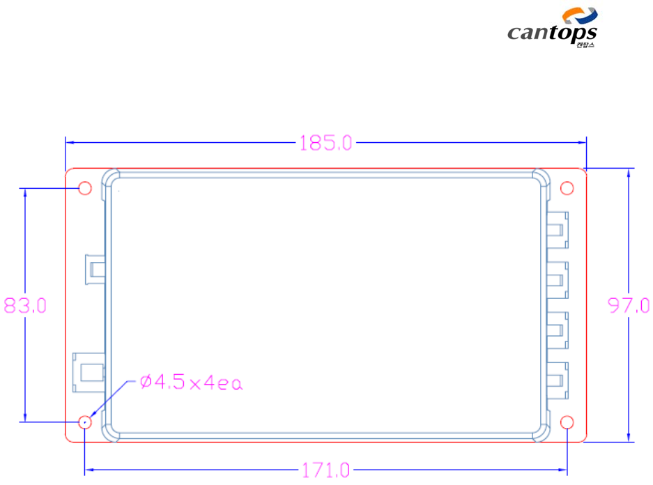
< Attachment 2> Dimension of fixing holes for RFID Reader

Version Date Details of revision Remarks
1.0 2011-08-22 Initial Revision
1.1 2012-09-06 2.4 Contents of manually operating section are
revised.
3.3 Contents of PDO Map list are revised.
3.4 Contents of PDO function list are revised.
◀