CARRIER Controls And HVAC Accessories Manual L0210307
User Manual: CARRIER CARRIER Controls and HVAC Accessories Manual CARRIER Controls and HVAC Accessories Owner's Manual, CARRIER Controls and HVAC Accessories installation guides
Open the PDF directly: View PDF ![]() .
.
Page Count: 20
Small Packaged Products
1-1/2 to 5 Tons (50/60 Hz) Accessory
Motormaster II Head Pressure Controller
Cancels: IlK 555A-18-36 IlK 555A-18-37
6-O2
Installation Instructions
Part Numbers
CPLOWAMB001A00,
CPLOWAMB002A00
NOTE: Read the entire instruction manual betore starting the
installation.
SAFETY CONSIDERATIONS
Installation. start-up and servicing of this equipment can be
hazardous due to system pressures, electrical components, and
equipment location troofs, elevated structures, etc.)
Only trained, qualified installers and service technicians should
install, start up, and service this equipment.
When working on this equipment, observe precautions in the
literature, tags. stickers, and labels attached to the equipment, and
any other solely precautions that may apply.
INTRODUCTION
These instructions cover the installation of the Motormaster 11
Controller head pressure control device. Refer to the Installation
section t_r directions. Louvered panels are required for this
installation: see Note 9 in the Installation section of this document
and Tables I and 2 for more information.
Table 1--Add Louvered Panels to These Units
48GS 582A PY1P-B
48GX 583A PY2P-B
50GS 701A PAIP-B
50GX 702A PA2.P-B
50JS 601A PH1P-B
50JX 602A PH2P-B
Table 2--Do NOT Add Louvered Panels to These
Units
DESCRIPTION AND USAGE
The Motormaster II head pressure controller is acycle control
device activated by a temperature sensor mounted on a header tube
of the outdoor coil (see Fig. I/. II is designed to cycle the
outdoor-tan motors to maintain the saturated condensing tempera-
ture within normal operating limits of approximately 130 to 110°F
high. 70 to 50°F low 155M.3°C high. 21 to IO°C low). The
controller maintains working head pressure at low ambient tem-
peratures down to -20:'F when properly installed.
INSTALLATION
1. Disconnect power to unit. h_stall lockout tag,
2. Remove unit access panel.
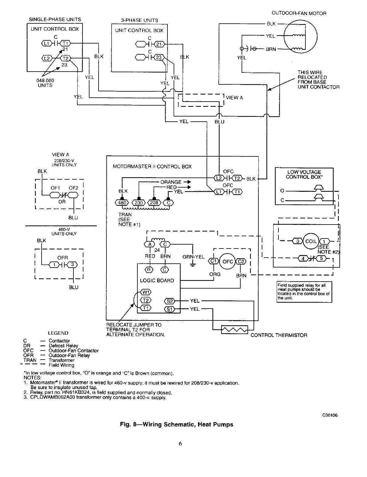
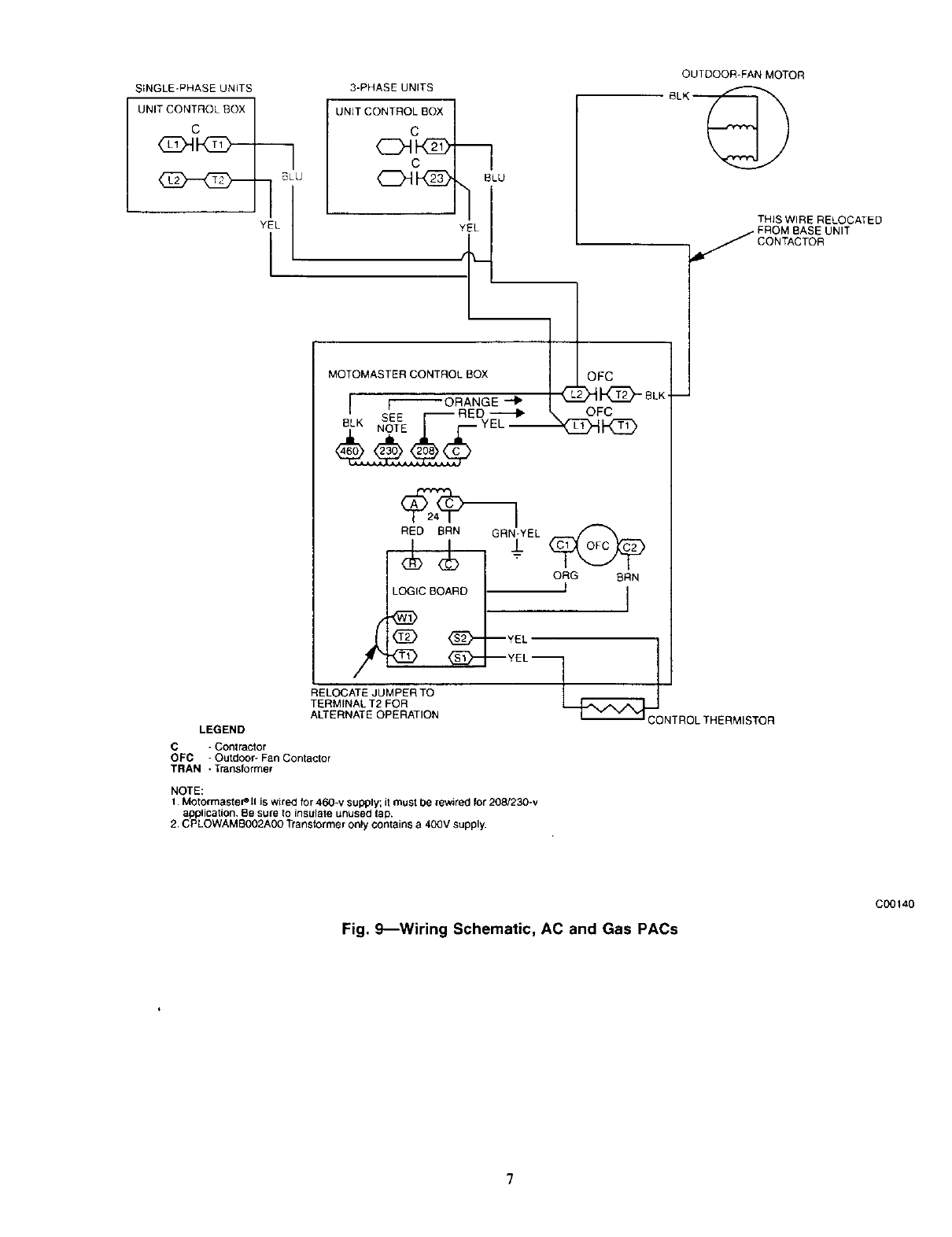
3. Disconnect outdoor-fan motor (OFM). (See Wiring Sche-
mauc. Fig. 8 or 9)
4. Remove OFM wires from unit control box.
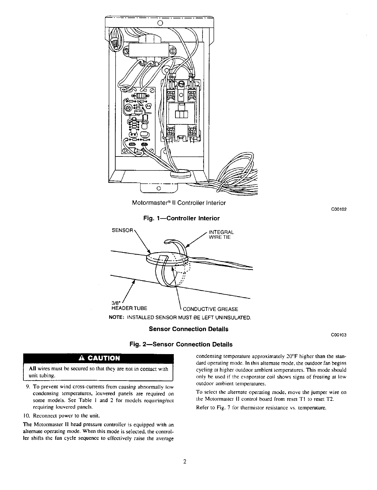
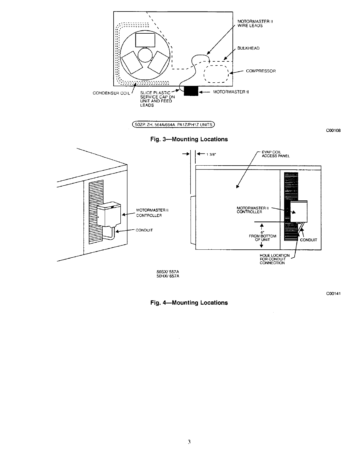
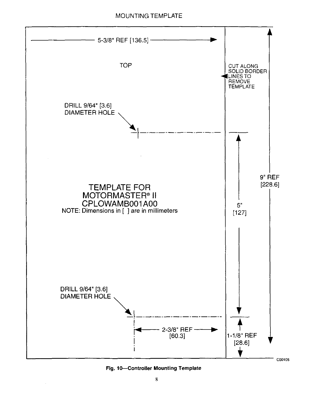
5. Mount Motormaster II Controller on unit. Refer to Fig. 3-6.
The controller must be mounted vertically with the leads at the
bottom. Using the Mounting Template (Fig. 10) as a guide.
drill mounting holes. To ensure electrical ground, insert star
washers (supplied with the controller) under the heads of
mounting screws.
NOTE: Field-supplied conduit must be used between controller
and access panel (or wire into unit entrance).
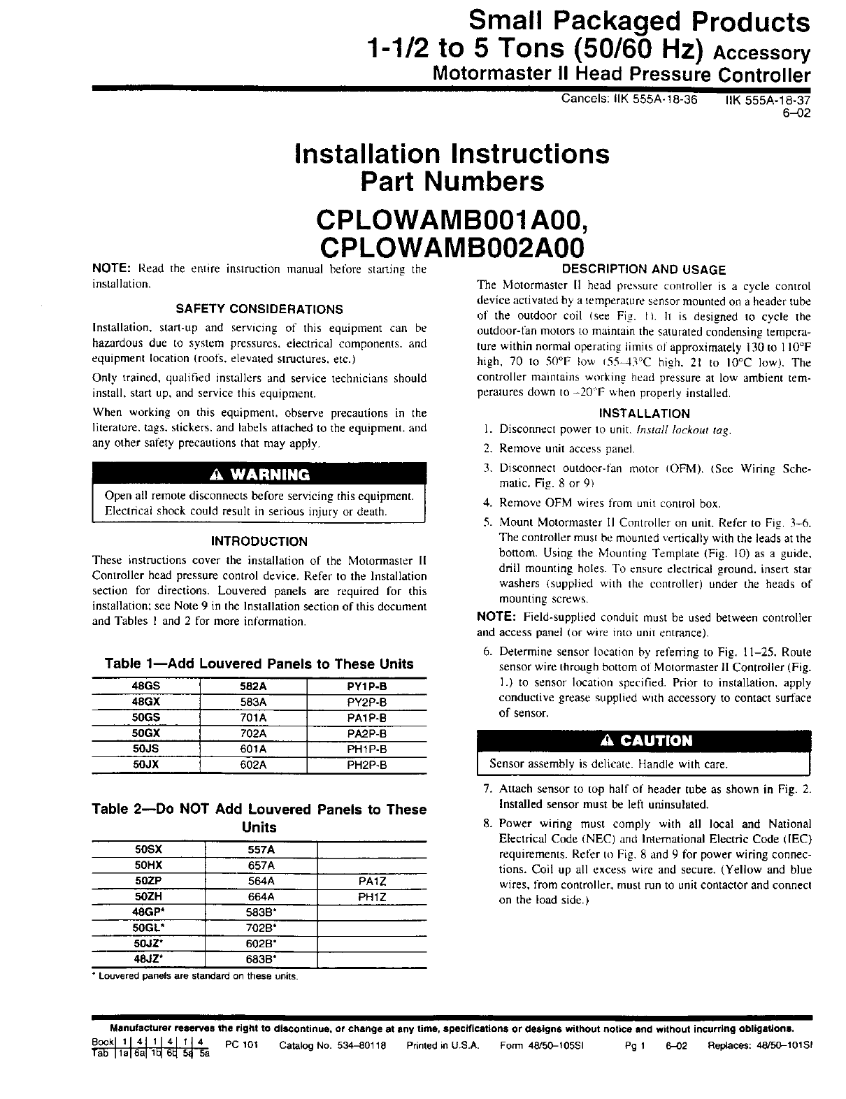
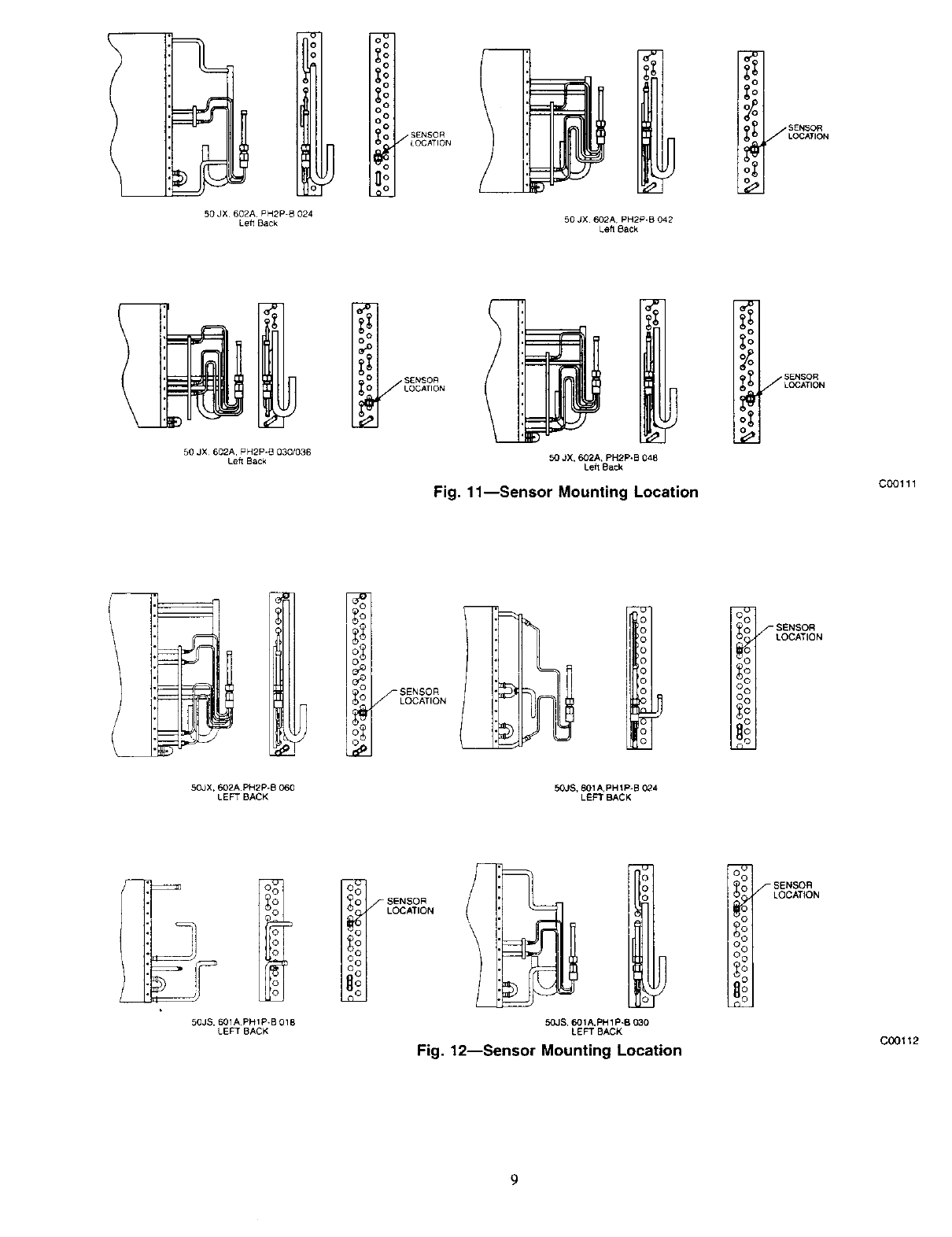
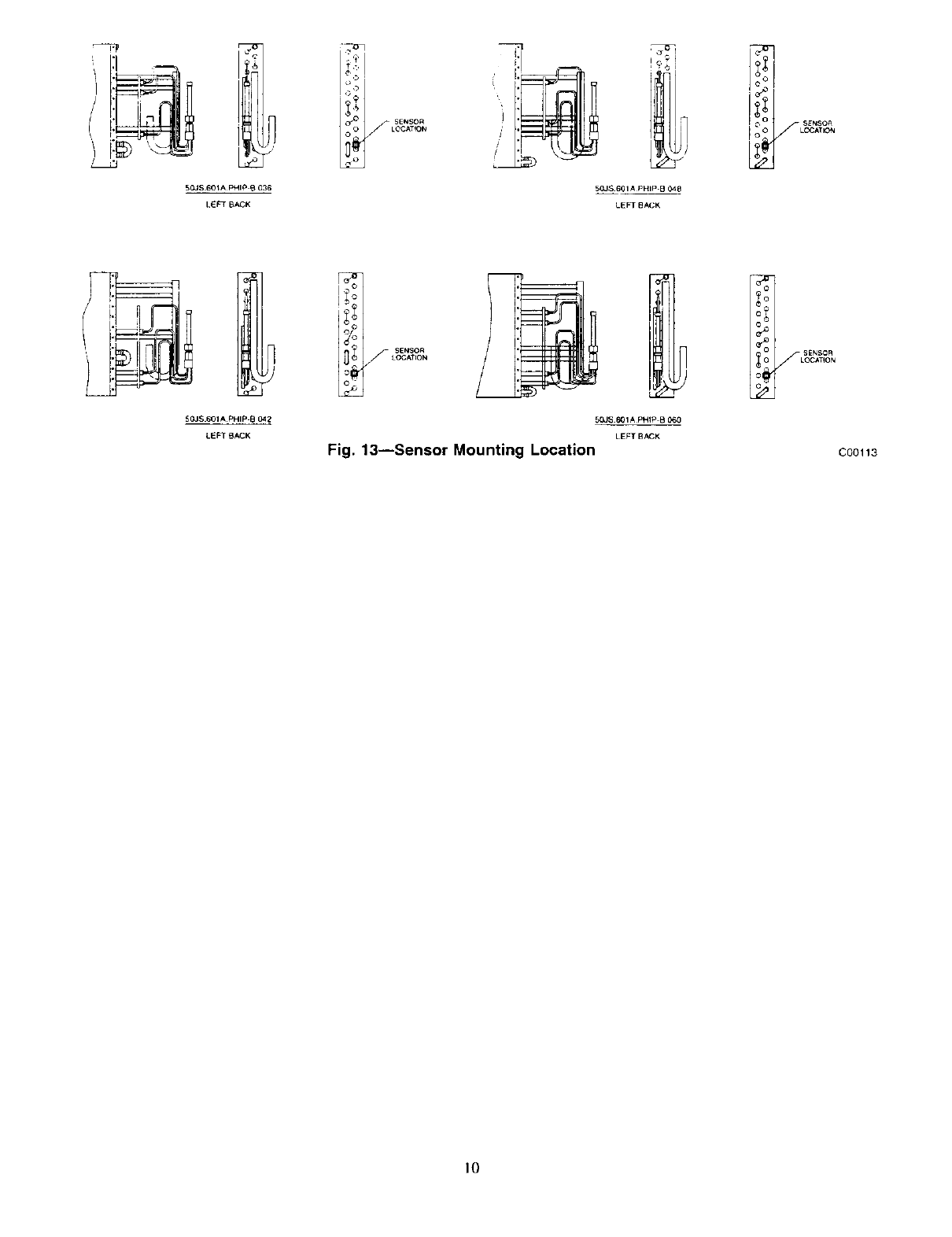
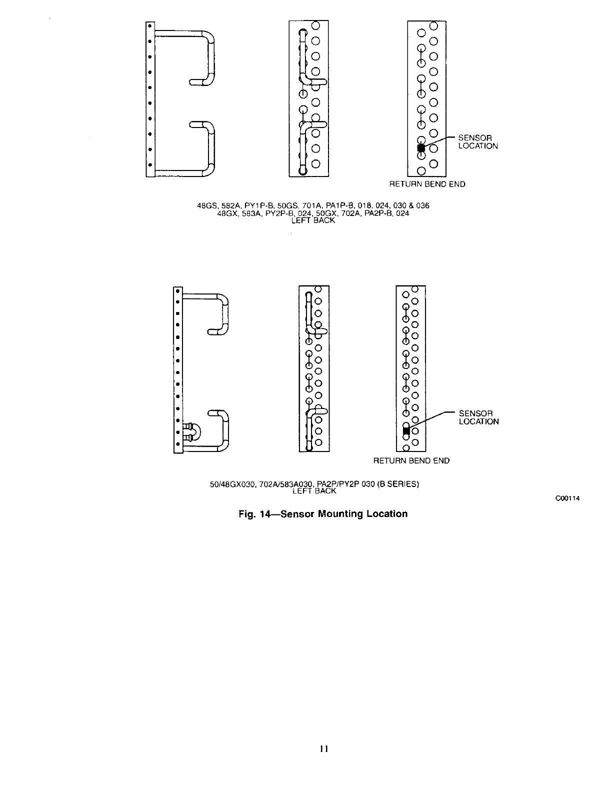
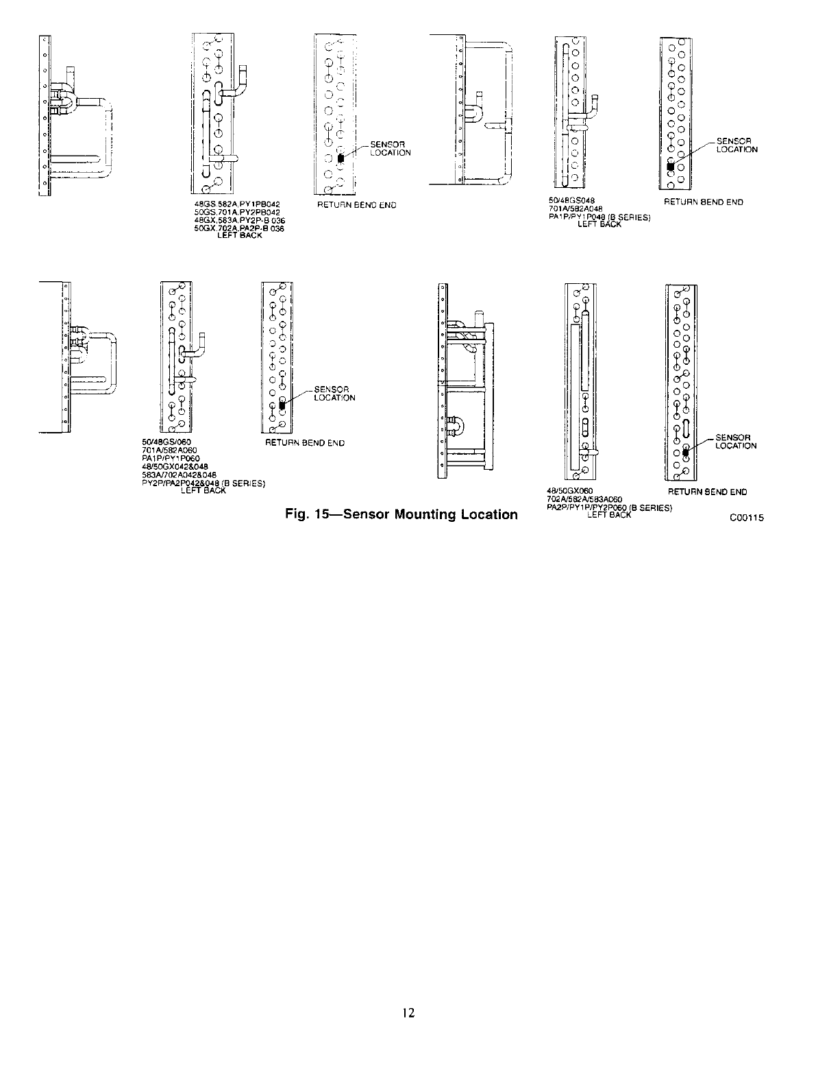
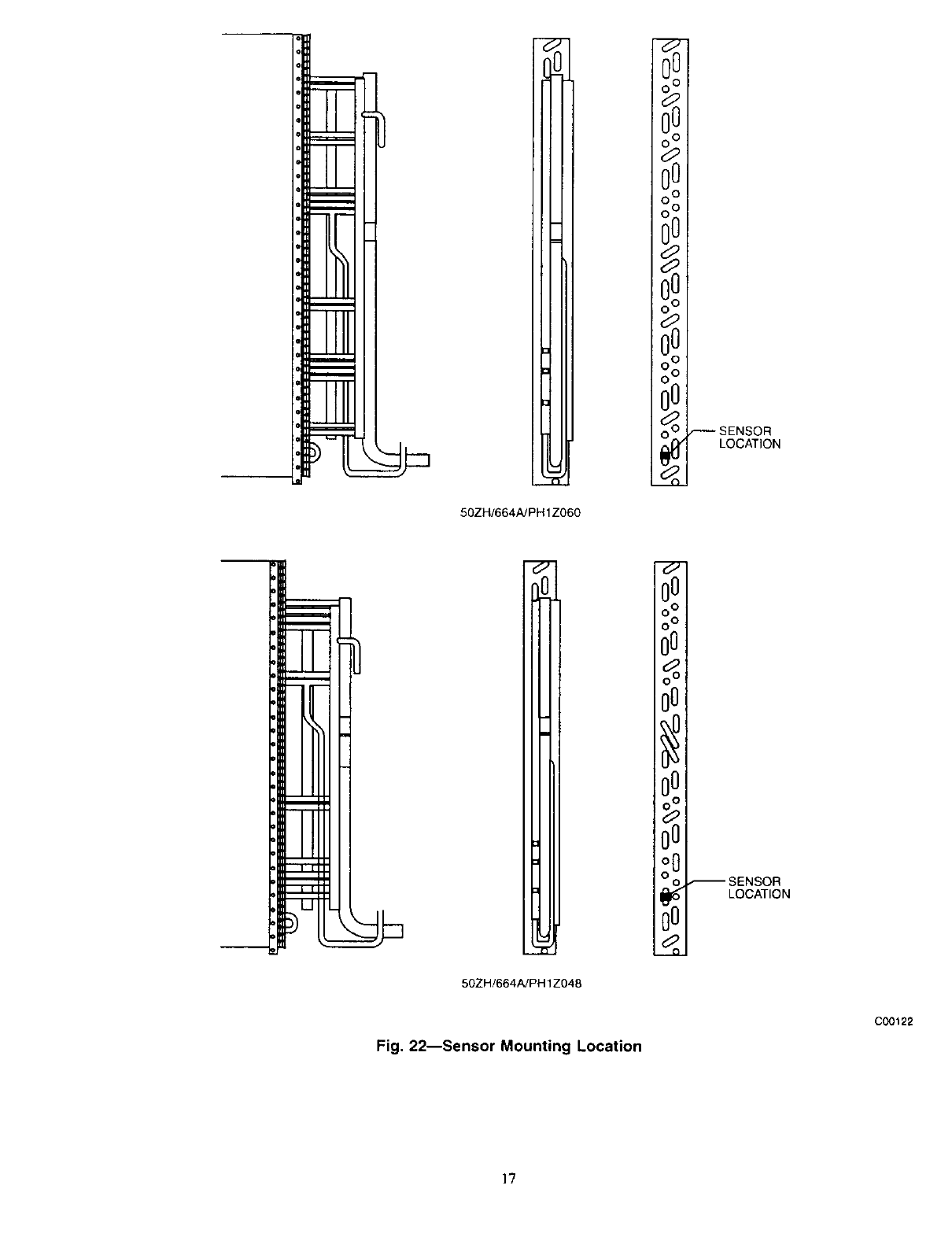
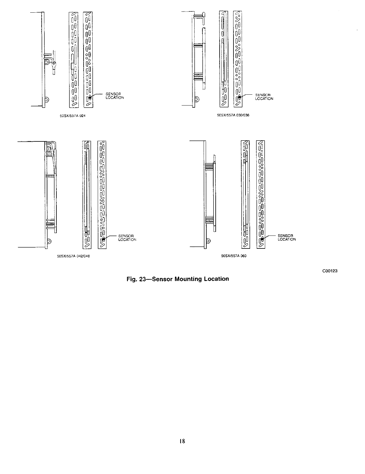
6. Determine sensor location by referring to Fig. 11-25. Route
sensor wire through bottom ol Motormaster II Controller (Fig.
l.) to sensor It,cation specified. Prior to installation, apply
conductive grease supplied with accessory to contact surface
of sensor.
50SX
50HX
50ZP
50ZH
48GP*
50GL*
50JZ"
48JZ*
557A
657A
564A PA1Z
664A PHIZ
583B"
702B*
602B*
683B*
7. Attach sensor to top half of header tube as shown in Fig. 2.
Installed sensor must be left uninsulated.
8. Power wiring must comply with all local and National
Electrical Code (NEC) and International Electric Code dEC)
requirements. Rel)r to Fig. 8 and 9 for power wiring connec-
tions. Coil up all excess wire and secure. (Yellow and blue
wires, from controller, must run to unit contactor and connect
on the load side.)
•Louvered panels are standard on these units.
Manufacturer reserves the right to discontinue, or change at any time, specifications or designs without notice and without incurring obligations,
BOOkI1141 1_4 PClOt Catalog No. 53440118 Printedin U.S.A. Form 48/50-105S1 Pgl 602 Replaces: 48/50-101S,
Tab la 6a 1 5a
O
I o
Motormaster e II Controller Interior
Fig. 1--Controller Interior
SENSOR\ / INTEGRAL
WIRE TIE
NOTE: INSTALLED SENSOR MUST BE LEFT UNINSULATED.
C00102
Sensor Connection Details
C00103
Fig. 2--Sensor Connection Details
9. To prevent wind cross-currents from causing abnormally low
condensing temperatures, louvered panels are required on
some models. See Table I and 2 for models reqmring/not
requiring Iouvered panels.
I0. Reconnect power to the unit.
The Motormasler I1 head pressure controller is equipped with an
alternate operating mode. When this mode is selected, the control-
ler shifts the fan cycle sequence to effectively raise the average
condensing temperature approximately 20°F higher than the stan-
dard operating mode. In this alternate mode, the outdoor fan begins
cycling at higher outdoor ambient temperatures. This mode should
only be used if the evaporator coil shows signs of frosting at low
outdoor ambient temperatures.
To select the alternate operating mode. move the jumper wire on
the Motormaster I1 control board from reset TI to reset T2.
Refer to Fig. 7 for thermistor resistance vs. temperature.
\\ MOTORMASTER!!
WIRELEADS
, BULKHEAD
3SOR
CONDENSER CO4L SERVICE CAP DN
UNIT AND FEED
LEADS
MOTORMASTERII
J
(5OZR ZH, 564N664A PA1Z/PHIZ UNITS)
C00108
Fig. 3--Mounting Locations
MOTORMASTERII
_CONTROLLER
_CONDUIT
1 3/8"
/
/
MOTORMASTERII
CONTROLLER
t,
6"
FROM BOTt'O M
OF UNiT
HOLE LOCATION
FOR CONDUIT
CONNECTION
50SXJ557A
50HX/657A
Fig. 4--Mounting Locations
000141
MOTORMASTERII---_
/_-BULKHEAD
MOTORMASTERIt
P WIRE LEADS
SLICE PLASTIC
SERVICE CAP ON
UNIT AND FEED LEADS COMPRESSOR
I 48/50GS. GX. JS, JX, G£ GL, JZ UNITS
582A/701A. 583A/702A, 601A, 602A, 583B, 702B, 602B,6838 JPYlP-B/PA1P B, PY2P-B/PA2P-B, PHIP-B, PH2P-B
CSMALL CABINET)
Fig. 5--Mounting Locations-Small Cabinet
000109
BULKHEAD--
MOTORMASTERII--_
"_o-O" q
SLICE PLASTIC
SERVICE CAP ON COMPRESSOR
UNIT AND FEED LEADS
(582 pAfZyO1pA4/_A301pGA_.SoB2GAp,Xy62_O!:A',/_!,G,_.Z_N!TpHX2BB_3B)
(LARGE CABINET)
Fig. 6--Mounting Locations-Large Cabinet
_-- MOTORMASTER II
WIRE LEADS
COO110
4
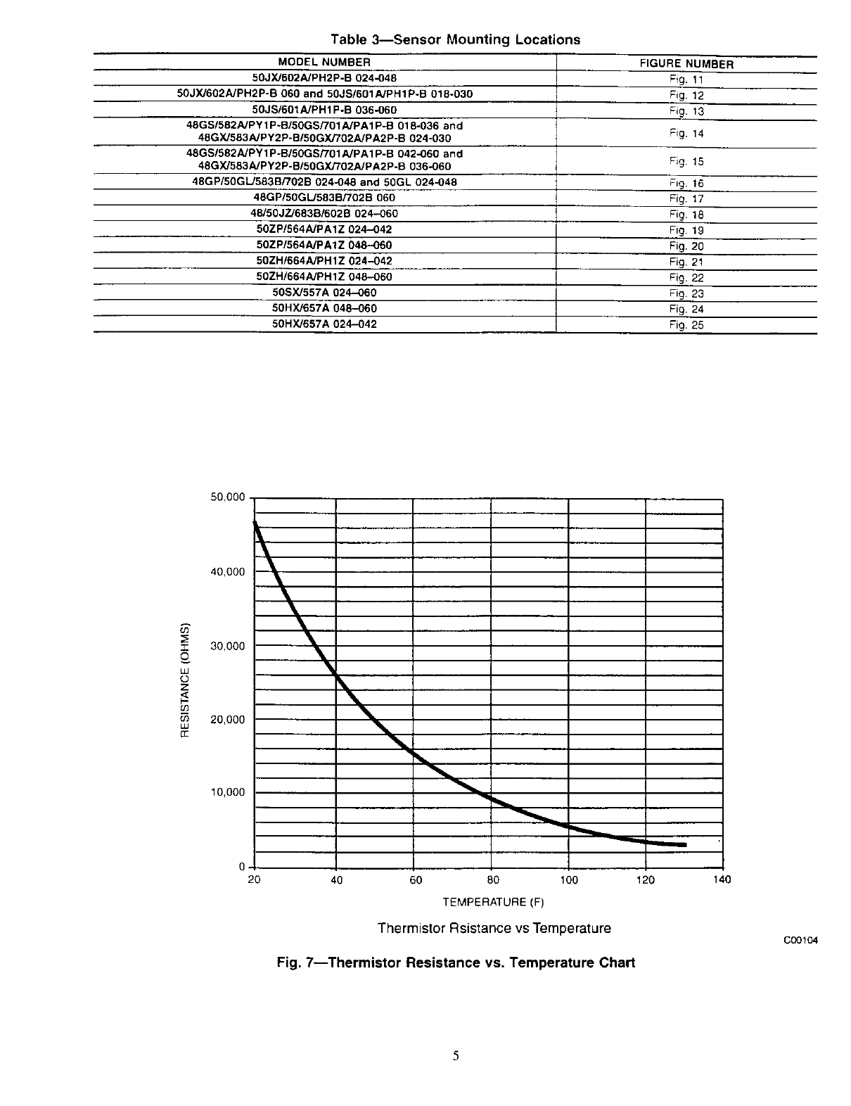
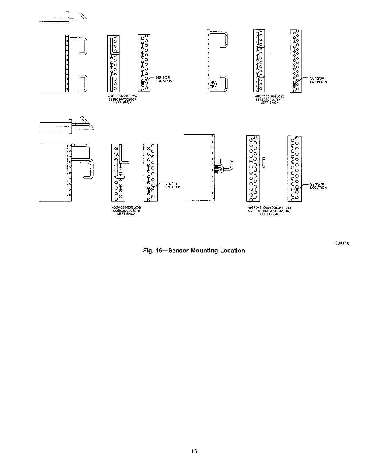
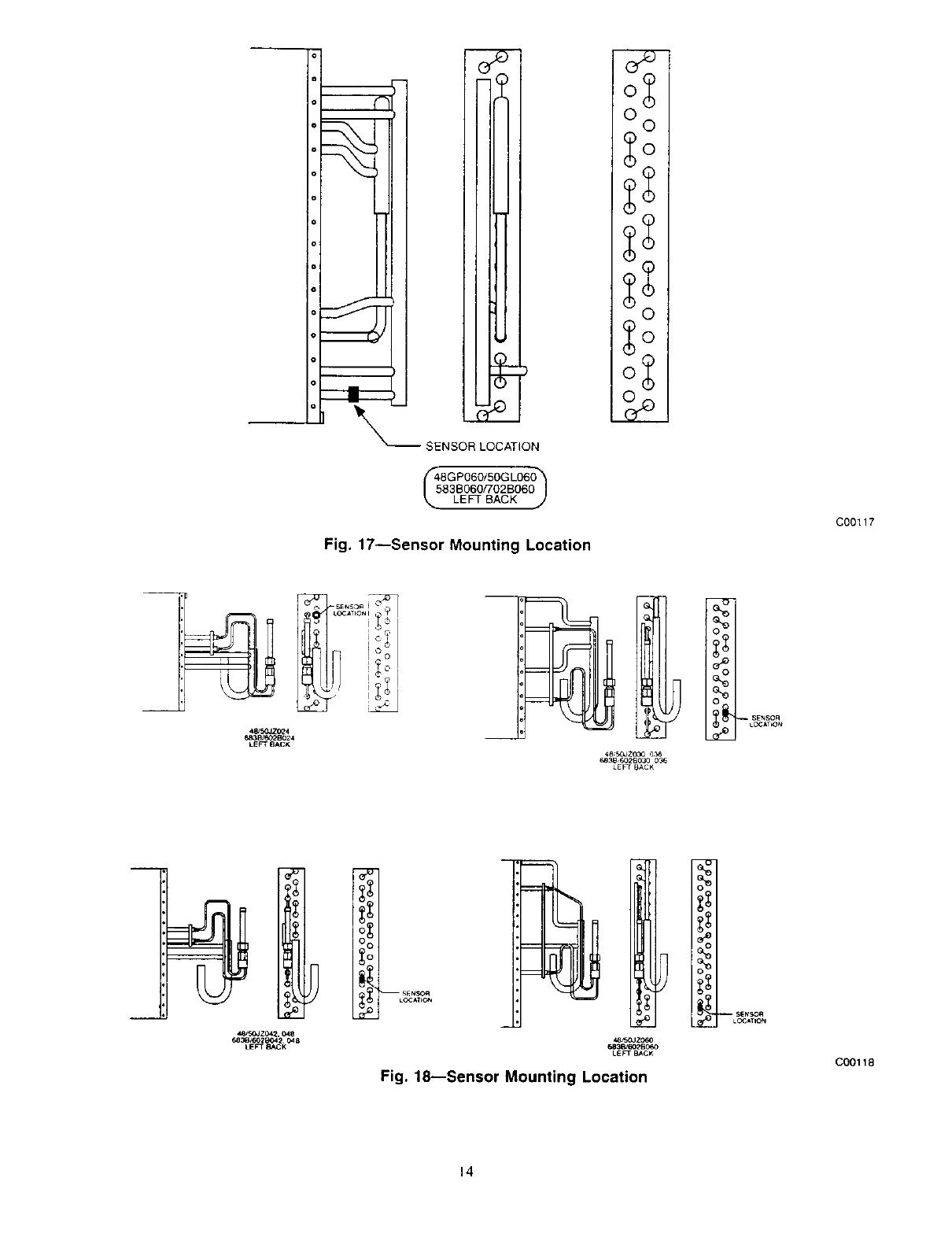
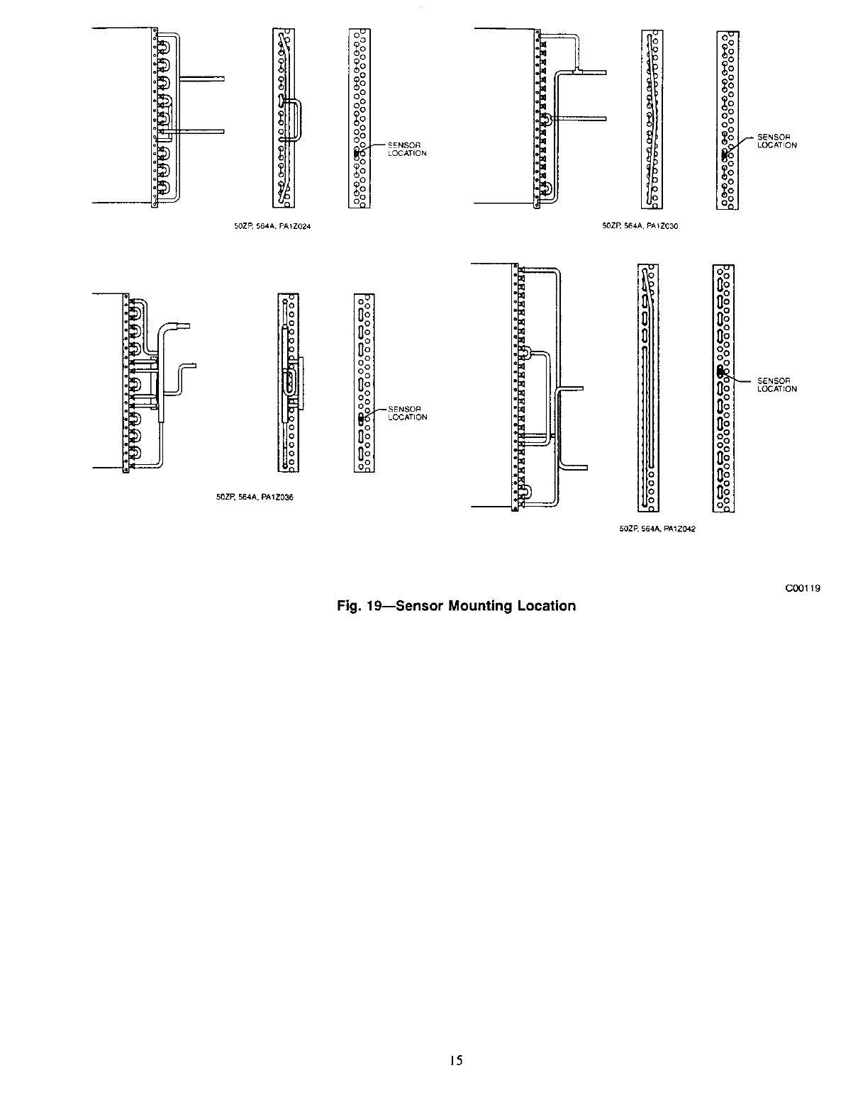
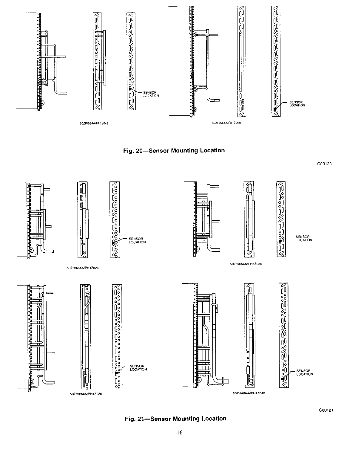
Table 3--Sensor Mounting Locations
MODEL NUMBER
50JX/602A/PH2P-B 024-048
50JXJ602A]PH2P-B 060 and 50JS/601AJPH 1P-B 018-030
50JS/601A/PH 1P-B 036-060
48GS/582A/PY 1P-B/50GS/701 A/PAl P-B 018-036 and
48G X/583A/PY2 P-B/50GXF/02A/P A2 P-B 024-030
48GS/582A/PY 1P-B/50GS/701A/PA1 P-B 042-060 and
48G XJ583A/PY2 P-B/50GYJT02AJPA2 P-B 036-060
48GP/50GL/583B/702B 024-048 and 50GL 024`048
48GP/50GL/583B/702B 060
48/50JZ/683B/602B 024-060
50ZP/564AJPA1Z 024-042
50ZP/564A/PA1Z 048-060
50ZH/664A/PH 1Z 024-042
50ZH/664A/PH1Z 048-060
50SX/557A 024-060
50HX,'657A 048-060
50HXJ657A 024-042
FIGURE NUMBER
Fig. 11
Fig, 12
Fig. 13
Fig. 14
Fig. 15
Fig, 16
Fig. 17
Fig. 18
Fig. 19
Fig. 20
Fig. 21
Fig. 22
Fig. 23
Fig. 24
Fig. 25
I
LU
o
z
03
LU
(]£
50,000
40,000
30,000
20,000
10,000
0
\
2O 4O 60 80 100
TEMPERATURE (F)
Thermistor Rsistance vs Temperature
120 140
Fig. 7--Thermistor Resistance vs. Temperature Chart
C00104
5
SINGLE-PHASE UNITS
UNITCONTROLSOX
C
<Z>-I_ m
048.060
UNITS
C
BLK
3-PHASE UNITS
UNIT CONTROL BOX
C
C
BLK <_ LK
I Y
YEL
-_YEL --
VIEW A
208/230-V
UNITS ONLY
F I OF1 OF2 I
I I
L I_1
BLU
MOTORMASTER II CONTROL BOX
1 VIEW A
BLU
OUTDOOR-FAN MOTOR
BLK_ )
YEL
[
OFC
460-V
UNITS ONLY
THIS WIRE
RELOCATED
/FROM BASE
UNIT CONTACTOR
LOW VOLTAGE
BLK
,r ,
OFR I
I I
tI
BLU
LEGEND
-- Contactor
DR -- Defrost Relay
OFC Outdoor-Pan Contactor
(]_"I_"_BLK
r----------ORANGE--_
J I t'-"_RED'--_ ' OFC
TRAN
(SEE
NOTE #1)
@ @
--<ZD
RELOCATE JUMPER TO
TERMINAL T2 FOR
ALTERNATE OPERATION.
r
RED BRN GRN°YEL
LOGIC BOARD
r-
ORG BRN --
' 1
CONTROLBOX*
o_.._._...,z:%__
I
I
NOTE #2
..... _]
1
--J
It ield suppliedrelay for all
Heat pumpsst_ouldbe
located in the control box of
-- YEL he unit.
--YEL_
CONTROL THERMISTOR
OFR -- Outdoor-Fan Relay
TRAN -- Transformer
.... Field Wiring
*In low voltage control box, "O" is orange and "C" is Brown (common).
NOTES:
1. Motomasteff' II transformer is wired for 460-v supply; it must be rewired for 208/230-v application.
Be sure to insulate unused tap.
2. Relay, part no. HN61KB324, is field supplied and normally closed.
3. CPLOWAMB002A00 transformer only contains a 400-v. supply.
Fig. 8_Wiring Schematic, Heat Pumps
C00106
;INGLE-PHASE UNITS
UNIT CONTROL BOX
c--7
_LU
YEL
I
3-PHASE UNITS
UNIT CONTROL BOX
C
CC_KZ5-
c
BLU
Y
MOTOMASTER CONTROL BOX OFC
, _r_---_t_.g_-*/ c__,._. oF_SLK
OUTDOOR-FAN MOTOR
6LK-_
THIS WIRE RELOCATED
FROM BASE
S CONTACTOR UNIT
RED BRN GRN-YEL
LOGIC BOARD
.{_>
RELOCATE JUMPER TO
TERMINAL T2 FOR
ALTERNATE OPERATION
ORG BRN
'1
--YEL _'--I ONTRO L
THERMISTOR
LEGEND
C- Contractor
OFC -Outdoor- Fan Contactor
TRAN - Transformer
NOTE:
1. MotorrnastePII is wired for 460-v supply; it must be rewired for 208/230-v
application. Be sure to insulate unused lap.
2. CPLOWAMB002A00 Transformer only contains a 400V supply.
Fig. 9--Wiring Schematic, AC and Gas PACs
C0{J140
?
MOUNTING TEMPLATE
5-3/8" REF [136.5]
TOP
DRILL 9/64" [3.6]
D,AMETER HOLE _'_t
TEMPLATE FOR
MOTORMASTER ®II
CPLOWAMB001A00
NOTE: Dimensions in [ ] are in millimeters
DRILL 9/64" [3.6]
DIAMETER HOLE
_1-- 2÷3/8" REF
[60.3]
CUT ALONG
SOLID BORDER
"1|LINES TO
REMOVE
TEMPLATE
5"
[127]
I-1/8" REF
[28.6]
Fig. lO_ControUer Mounting Template
9" REF
[228.6]
C00105
]_
50 JX 602A PH2P-8 024
Left Back
[o
,_o
_o
1]o
_o
SENSOR
/LOCATION
50 JX. eO2A, PH2P-B 042
Lefl Back
%
LOCATION
M_
50 JX 602A RH2P-B 030/036
Left Back
.-SENSOR
• _ ,/LOC ATION
50 JX, 602A. PH2P-B 048
Left Back
Fig. 11--Sensor Mounting Location
Y_
_r
SENSOR
?& /LOCATION
C00111
/
L_
Z
9LOCATION _:o° BENSO.
_0 _- LOCATION
:3
go_
50JX, 602A.PH2P-B 060
LEFT BACK 50JS, 6OlA, PH1P-B 024
LEFT BACK
50JS. 601A PH1P-B 018
LEFT BACK
:_o SENSOR
LOCATION
50JS, 601A.PHIP-8 030
LEFT BACK
Fig. 12--Sensor Mounting Location
_;o
_o
FSENSOR
LOCATION
C00112
9
/
50JS 60$A pHIp-B 036
L_FT BACK
5_S 601A PHIP _ 048
LEN B _,f_K
50JS.601A PHIP-8 (_2
LEFT B_*CK
9
50JS 601A PHIP-B 060
LEFT BACK
Fig. 13--Sensor Mounting Location
oi
S_NSOR
J v /=LOCATK_N
/
C00113
10
_oi
qDOI
©1
ll
0'_
..on
_oi
_Ol
_0
SENSOR
LOCATION
SOl
RETURN BEND END
48GS, 582A, PY1P-B, 50GS, 701A, PA1P°B, 018, 024,030 & 036
48GX. 583A, PY2P-B, 024, 50GX> 702A, PA2P-B, 024
LEFT BACK
on
Oi
O_
0
0
0
0
0
o
o
o
0--9-_
O _ SENSOR
LOCATION
RETURN BEND END
50/48GX030,702_583A030, PA2P/PY2P 030(8 SERIES)
LEFT BACK
Fig. 14--Sensor Mounting Location
C00114
I]
IML_q_
I!7]_Ir
48GS 582A, PY1PBO42
50GS.701A, PY2PB042
48GX.583A, PY2 P=B 036
50GX.702A.PA2P-B 036
LEFT BACK
- _;F SENSOR
L ;j,4 LOCAT ON
.O ;
I
PETURN NENB END 50/48GS048
701AJ582A048
PA1P/PY1P048(BSERIES)
LEFT BACK
O_7
8oo
O
i! _BENSOR
i_0_ _ LOCATION
RETURN 8END END
--H
50/48GS/060
701/V582A060
PAl P/PY IPC_0
48250GX042&048
583A/702AO42&048
RETURN BEND END
RY2P/PA2 P042&048 (B SERfES)
LEFT BACK
Fig. 15--Sensor Mounting Location
7
1
48/50GX060
702N582AJ583A060
PA2P/PY1P/PY2P080 B SERIES)
LEFt BAC_
RETURN BEND END
C00115
12
Eo
48GP024/50GL024
5838o24r7028024
LEFT BACK
o_-
:_o
_o
_o
_o-- SENSOR
LOCATJON
=3 O
O
#
o
o
o
o
o
Eb
0
0
0
48GP03_50GL030
5838030/7028030
LEFTBACK
O
48GP036150GL036
583B036/7028036
LEFT BACK
T
.._ v _" SENSOR
_1_ LOCATION !!
£
48GP042. 048/50GL042 048
5838042 048/702B042.04.9
LEFT BACK
_SENSOR
LOCATION
Fig. 16--Sensor Mounting Location
000116
]3
SENSOR LOCATION
(Z _8GP060/50GL06_
583B060/702B060
LEFT BACK
Fig. 17--Sensor Mounting Location
7
O©
C00117
48/5_ZO24
683B/eO2B024
LEFT BACK
li) L_ATION
%
4B;5_Z035 ,_
683B 602B030 O36
LEF BACK
48/5_Z042. 048
e8_2_042 048
LEFT IE_CK
L_ _Tl_
,U_5OJZO6O
_2B_oo
LEFT BACK
Fig. 18---Sensor Mounting Location
LC'3ATION
C00118
14
_)lp==== 1
50ZP 564A, PA1Z024
80°
o o
o o
_o
%o
_-- _ENSOR
LOCATION
_o
_o
50Z_ 564A. PAIZ030
_o
_o
I
/_,-SENSOR
LOCATION
1
50Zl_564A,PA1Z036
DO
I?
Io
Io
Ii
Io-
--SENSOR
LOCATION
=q
=q
=q
=a
=q
=_c===
=€===:
=a
=a
=a
5OZP, 564A, PA 1 Z04,2.
U£
l_s
v_
v_
1£
g_
I£
SENSOR
LOCATION
Fig. 19--Sensor Mounting Location
C00119
15
50ZP/564AYPAIZ048
oUl
ooi
O_
50ZP/564A/PA I Z060
SENSOR
LOCATION
Fig. 20--Sensor Mounting Location
C00120
1
50ZH/664A/PH ! Z024
SENSOR
LOCATION 1
50ZH/664A/PH 1 Z030
(IU
oli
60
nu
oll
-- SENSOR
LOCATION
flu
50ZI-_664A/PH 1 Z03_
_SENSOR
LOCATION
50ZH/664A/PH1Z042
0u
v_
v=
nu
nu
nu
nu
I10
oral_ SENSOR
LOCATION
_g
Fig. 21--Sensor Mounting Location
C00121
]6
50ZH/664A/PH 1Z060
v
NU
_v
v
nu
AV
NU
Av
nu
nu
VA
_v
nu
_v
nu
fJ
v_ SENSOR
LOCATION
50ZH/664A!PH 1Z048
0o
oo
oo
O0
O0
0o
0o
Oil
_ SENSOR
LOCATION
rllJ
Fig. 22--Sensor Mounting Location
C00122
]?
IlUl
Oj!i nui
00 nu:
O0 nu
00o
_ll ol!
_ nu
flu
nU
nu
_ 0_
50SX/557A 024
SENSOP
LOCATION
m
I
_P
nul
fl!!
nUI
nu
nu
IIU
X_
BU
nu SENSON
I]1_I" LOCATION
50SX/557A 030/036
--SENSOR
LOCATION
50SXJ557A 042J'048 50SX]557A 060
_lU
llU
nu
nu
nU
flu
flU
nu
Ou
_0__ SENSO.
LOCATION
_p
Fig. 23--Sensor Mounting Location
C00123
18
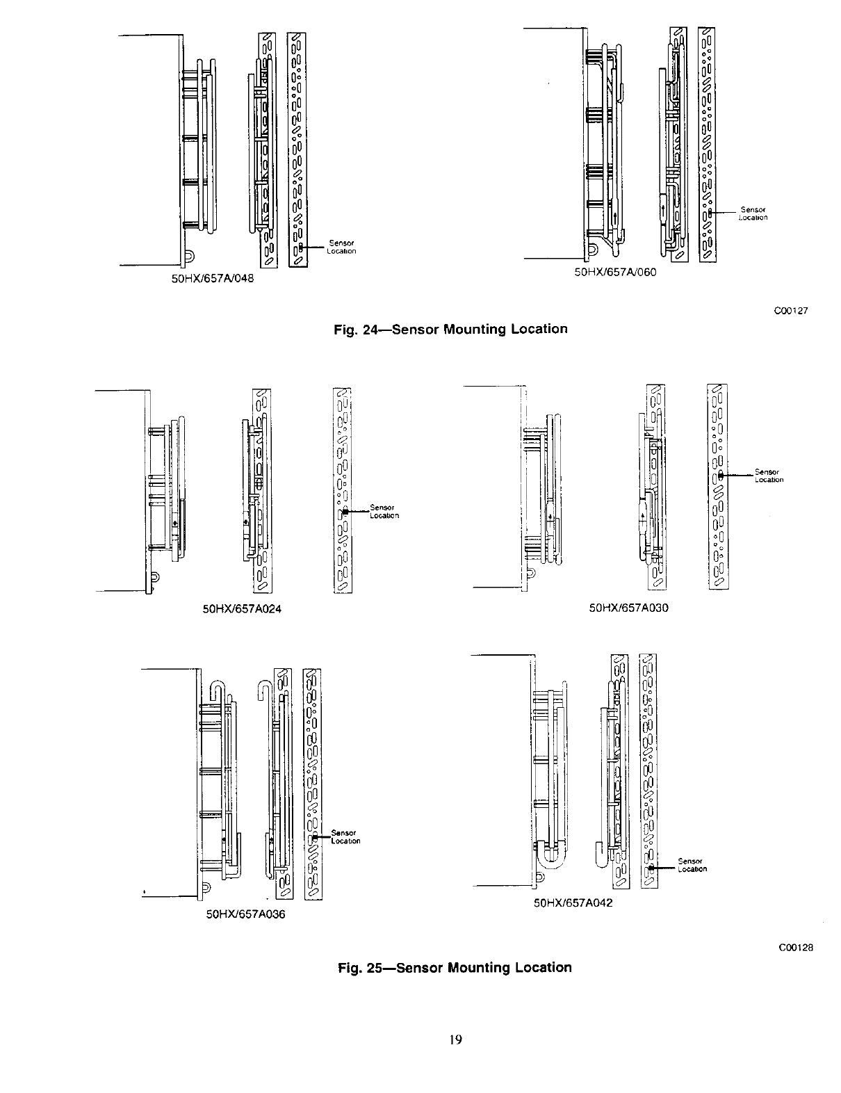
50HX/657A/048
_u
JO
ol
nu
_U
nu
nu
00
flu
n_
u__
S_SOr
-- Lo_llorl
50HX/657Ai060
Sensor
Location
Fig. 24--Sensor Mounting Location
C00127
50HX/657A024
: 0, s..,o,
0_ LOCk-iOn
Oo
O0
o o
Oo
50HX/657A030
Sensor
--Location
J
50HX/657A036
I! i,
50HX/657A042
!
Se_r
-- L oCatlon
Fig. 25---Sensor Mounting Location
C00128
19

Copyright 2002 Carrier Corporation 555a1837
Manufacturer reserves the right to discontinue, or change at any time, specifications or designs without notice and without incurring obligations.
Tab Ilal 16a lb_61_ 5_ 5a
