CARRIER Controls And HVAC Accessories Manual L0210315
User Manual: CARRIER CARRIER Controls and HVAC Accessories Manual CARRIER Controls and HVAC Accessories Owner's Manual, CARRIER Controls and HVAC Accessories installation guides
Open the PDF directly: View PDF ![]() .
.
Page Count: 4
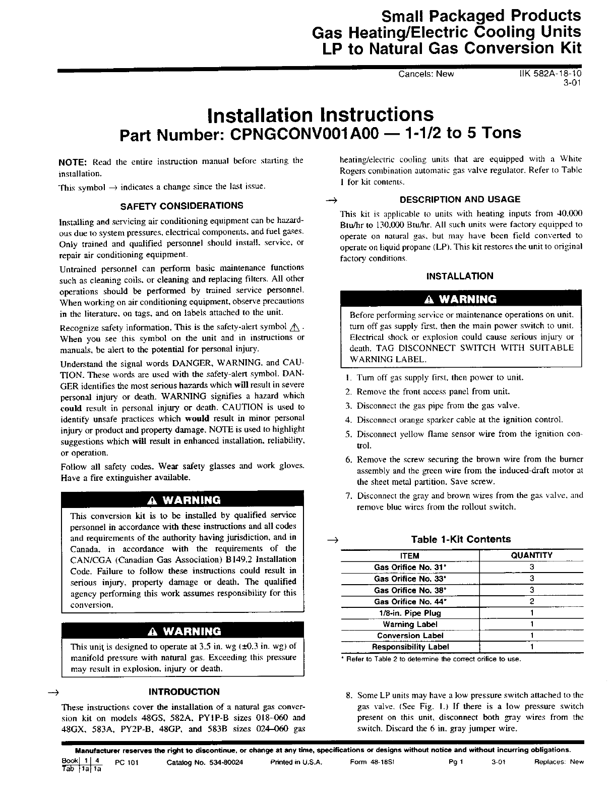
Small Packaged Products
Gas Heating/Electric Cooling Units
LP to Natural Gas Conversion Kit
Cancels: New LIK 582A-18-10
3-01
Installation Instructions
Part Number: CPNGCONV001A00 -- 1-1/2 to 5 Tons
NOTE: Read the entire instruction manual before starting the
installation.
This symbol _ indicates a change since the last issue.
SAFETY CONSIDERATIONS
Installing and servicing air conditioning equipment can be hazard-
ous due to system pressures, electrical components, and fuel ga.qes.
Only trained and qualified personnel should install, service, or
repair air conditioning equipment.
Untrained personnel can perform basic maintenance functions
such as cleaning coils, or cleaning and replacing filters. All other
operations should be performed by trained service personnel.
When working on air conditioning equipment, observe precautions
in the literature, on tags, and on labels attached to the unit.
Recognize safety information. This is the safety-alert symbol _.
When you see this symbol on the unit and in instructions or
manuals, be alert to the potential for personal injury.
Understand the signal words DANGER, WARNING. and CAU-
TION. These words are used with the safety-alert symbol. DAN-
GER identifies the most serious hazards which will result in severe
personal injury or death. WARNING signifies a hazard which
could result in personal injury or death. CAUTION is used to
identify unsafe practices which would result in minor personal
injury or product and property damage. NOTE is used to highlight
suggestions which will result in enhanced installation, reliability,
or operation.
Follow all safety codes. Wear safety glasses and work gloves.
Have a fire extinguisher available.
r_' k','l:._;] ='1_ ["]
This conversion kit is to be installed by qualified service
personnel in accordance with these instructions and all codes
and requirements of the authority having jurisdiction, and in
Canada. in accordance with the requirements of the
CAN/CGA (Canadian Gas Association) B 149.2 Installation
Code. Failure to follow these instructions could result in
serious injury, property damage or death. The qualified
agency performing this work assumes responsibility for this
conversion.
This unil is designed to operate at 3.5 in. wg (_+0.3 in. wgl of
manifold pressure with natural gas. Exceeding this pressure
may result in explosion, injury or death.
heating/electric cooling units that are equipped with a White
Rogers combination automatic gas valve regulator. Refer to Table
1 for kit contents.
DESCRIPTION AND USAGE
This kit is applicable to units with heating inputs from 40,000
Btu/hr to 130,000 Btu/hr. All such units were factory equipped to
operate on natural gas, but may have been field converted to
operate on liquid propane (LP/. This kit restores the unit to original
factory conditions.
INSTALLATION
Before performing service or maintenance operations on unit,
turn off gas supply first, then the main power switch to unit.
Electrical shock or explosion could cause serious injury or
death. TAG DISCONNECT SWITCH WITH SUITABLE
WARNING LABEL.
I. Turn off gas supply first, then power to unit.
2. Remove the front access panel from unit.
3. Disconnect the gas pipe from the gas valve.
4. Disconnect orange sparker cable at the ignition control.
5. Disconnect yellow flame sensor wire from the ignition con-
trol.
6. Remove the screw securing the brown wire from the burner
assembly and the _een wire from the induced-draft motor at
the sheet metal partition. Save screw.
7. Disconnect the gray and brown wires from the gas valve, and
remove blue wires from the rollout switch.
___) Table 1-Kit Contents
ITEM QUANTITY
Gas Orifice No. 31" 3
Gas Orifice No. 33" 3
Gas Orifice No. 38* 3
Gas Orifice No. 44* 2
1/8-in. Pipe Plug 1
Warning Label 1
Conversion Label 1
Responsibility Label 1
• Refer to Table2todeterminethe correct orifice to use.
--> INTRODUCTION
These instructions cover the installation of a natural gas conver-
sion kit on models 48GS, 582A, PYIP-B sizes 018_Yo0 and
48GX, 583A, PY2P-B, 48GP, and 583B sizes 024-060 gas
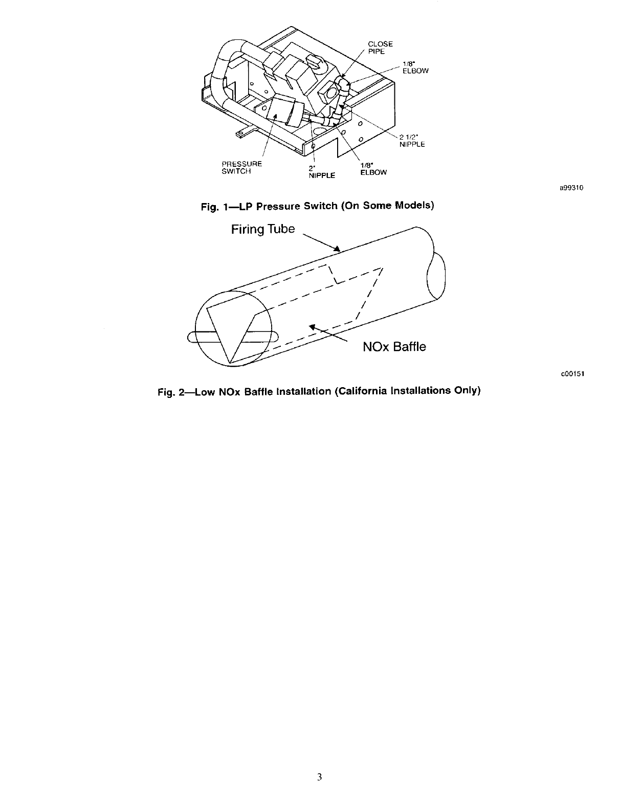
8. Some LP units may have a low pressure switch attached to the
gas valve. (See Fig. 13 If there is a low pressure switch
present on this unit, disconnect both gray wires from the
switch. Discard the 6 in. gray jumper wire.
Manufacturer reserves the right to discontinue, or change at any time, specifications or designs without notice and without incurring obligations.
PC t0t Catalog No. 534-80024 Pdnted in U.S.A. Form 48-18Sl Pg 1 3-01 Replaces: New
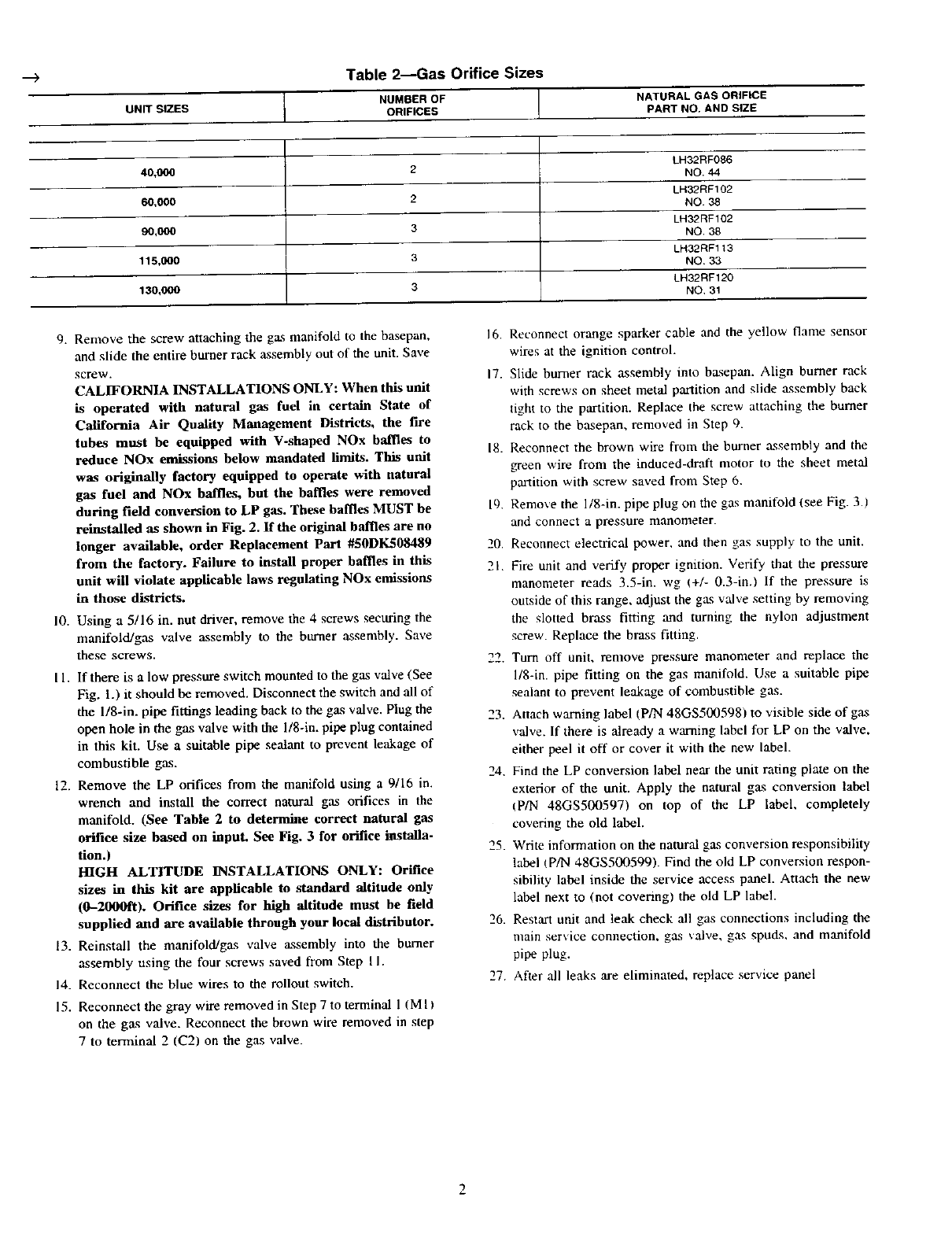
--_ Table 2--Gas Orifice Sizes
tNUMBER OF (NATURAL GAS ORIFICE
UNIT SIZES ORIFICES PART NO. AND SIZE
LH32RF086
40,000 2 NO. 44
LH32RF102
60,000 2 NO. 38
LH32RF102
90,000 3 NO. 38
LH32RF113
115,000 3 NO. 33
LH32RF120
130,000 3NO, 31
9. Remove the screw attaching the gas manifold to the basepan, 16.
and slide the entire burner rack assembly out of the unit. Save
screw. 17.
CALIFORNIA INSTALLATIONS ONLY: When this unit
is operated with natural gas fuel in certain State of
California Air Quality Management Districts, the fire
tubes must be equipped with V-shaped NOx baffles to 18.
reduce NOx emissions below mandated limits. This unit
was originally factory equipped to operate with natural
gas fuel and NOx baffles, but the baffles were removed
during field conversion to LP gas. These baffles MUST be 19.
reinstalled as shown in Fig. 2. If the original baffles are no
longer available, order Replacement Part #50DK508489 20
from the factory. Failure to install proper baffles in this 21.
unit will violate applicable laws regulating NOx emi_ions
in those districts.
10. Using a 5/16 in. nut driver, remove the 4screws securing the
manifold/gas valve assembly to the burner assembly. Save
these screws. 22.
I 1. If there is alow pressure switch mounted to the gas valve (See
Fig. 1.) it should be removed. Disconnect the switch and all of
the l/8-in, pipe fittings leading back to the gas valve. Plug the 23.
open hole in the gas valve with the l/8-in, pipe plug contained
in this kit. Use a suitable pipe sealant to prevent leakage of
combustible gas. 24.
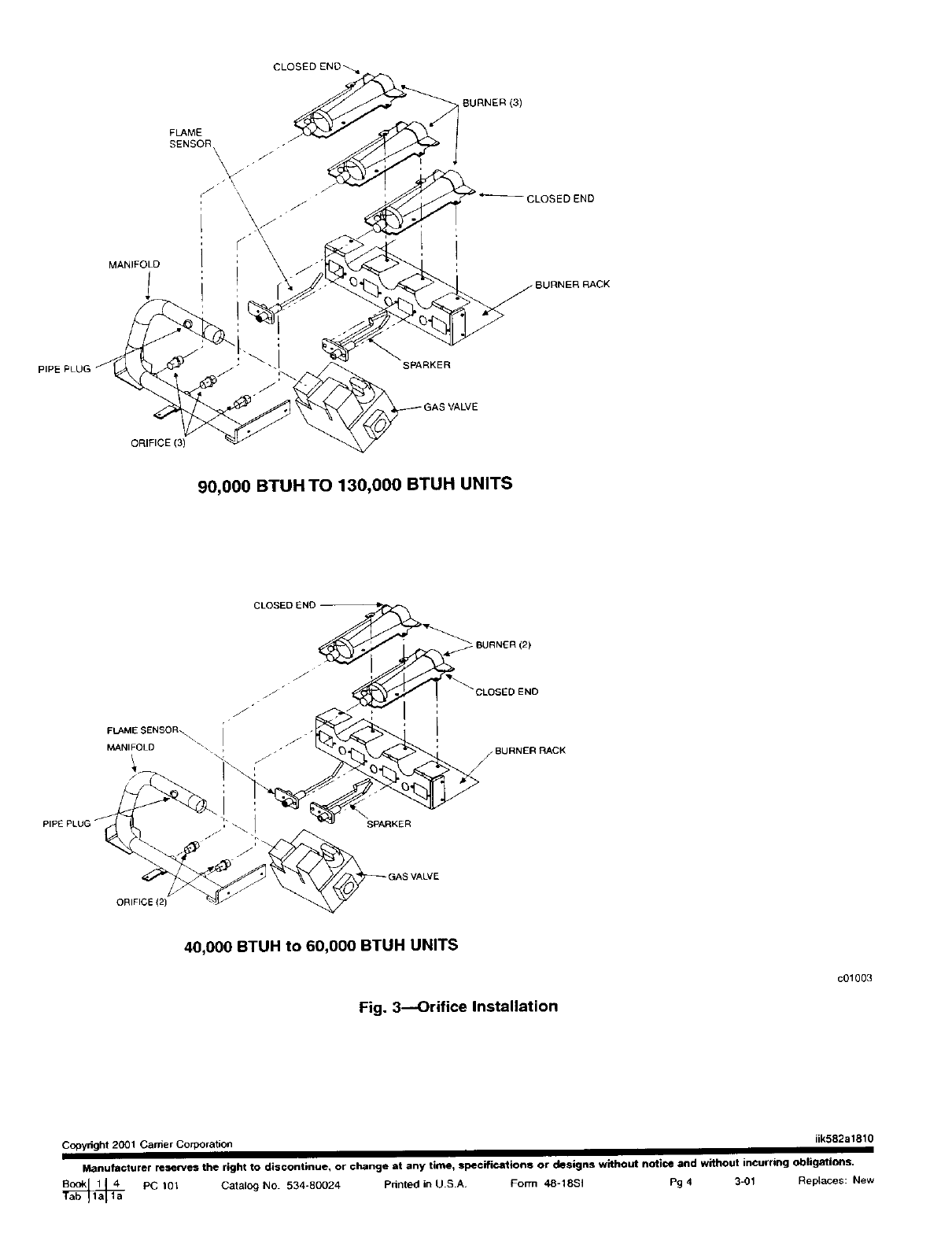
12. Remove the LP orifices from the manifold using a 9/16 in.
wrench and install the correct natural gas orifices in the
manifold. (See Table 2 to determine correct natural gas
orifice size based on input. See Fig. 3 for orifice installa-
tion.) 25.
H/GH ALTITUDE INSTALLATIONS ONLy: Orifice
sizes in this kit are applicable to standard altitude only
(0-2000R). Orifice sizes for high altitude must be field
supplied and are available through your local distributor. 26.
13. Reinstall the manifold/gas valve assembly into the burner
assembly using the four screws saved from Step I I.
14. Reconnect the blue wires to the rollout switch. 27.
15. Reconnect the gray wire removed in Step 7 to terminal 1 (M I I
on the gas valve. Reconnect the brown wire removed in step
7 to terminal 2 (C2) on the gas valve.
Reca)nnect orange spanker cable and the yellow t/ame sensor
wires at the ignition control.
Slide burner rack assembly into basepan. Align burner rack
with screws on sheet metal partition and slide assembly back
tight to the partition. Replace the screw attaching the burner
rack to the basepan, removed in Step 9.
Reconnect the brown wire from the burner assembly and the
_een wire from the induced-draft motor to the sheet metal
partition with screw saved from Step 6.
Remove the l/8-in, pipe plug on the gas manifold (see Fig. 3.)
and connect a pressure manometer.
Reconnect electrical power, and then gas supply to the unit.
Fire unit and verify proper ignition. Verify that the pressure
manometer reads 3.5-in. wg (+/- 0.3-in,) If the pressure is
outside of this range, adjust the gas valve setting by removing
the slotted brass fitting and mining the nylon adjustment
screw. Replace the brass fitting.
Turn off unit, remove pressure manometer and replace the
l/8-in, pipe fitting on the gas manifold. Use a suitable pipe
sealant to prevent leakage of combustible gas.
Attach warning label (P/N 48GS500598) to visible side of gas
valve. If there is already a warning label for LP on the valve,
either peel it off or cover it with the new label.
Find the LP conversion label near the unit rating plate on the
exterior of the unit. Apply the natural gas conversion label
(P/N 48GS500597) on top of the LP label, completely
covering the old label.
Write information on the natural gas conversion responsibility
label (P/N 4gGS500599). Find the old LP conversion respon-
sibility label inside the service access panel. Attach the new
label next to (not covering) the old LP label.
Restart unit and leak check all gas connections including the
main service connection, gas valve, gas spuds, and manifold
pipe plug.
After all leaks are eliminated, replace service panel
CLOSE
PIPE
ELBOW
PRESSURE 1/8"
SWITCH 2"
NIPPLE ELBOW
_2 1/2"
NIPPLE
Fig. 1--LP Pressure Switch (On Some Models)
Firing Tube
a99310
NOx Baffle
Fig. 2--Low NOx Baffle Installation (California Installations Only)
cO0151
FLAME
SENSOR
_URNER (3)
CLOSED END
MANIFOLD
-BURNER RACK
PIPE PLUG SPARKER
ORIFICE (3)
90,000 BTUH TO 130,000 BTUH UNITS
CLOSED E
FLAME SENSOR\ - j
PIPE PLUG jSPARKER
ORIFICE {2)
VALVE
40,000 BTUH to 60,000 BTUH UNITS
Fig. 3---Orifice Installation
c01003
Copyright 2001 Carr;er Corporation iik582a1810
ManufaGturer reserves the right to discontinue, or change at any time, specgieations or designs without notice and without incurring obligations.
PC 101 Catalo9 No 534-80024 Pnnted in U.S.A. F(_rrn 48-18SI P9 43-01 Replaces: New
