CARRIER Air Handler (indoor Blower&evap) Manual L0210322
User Manual: CARRIER CARRIER Air Handler (indoor blower&evap) Manual CARRIER Air Handler (indoor blower&evap) Owner's Manual, CARRIER Air Handler (indoor blower&evap) installation guides
Open the PDF directly: View PDF ![]() .
.
Page Count: 2
Installation Instructions
Downflow Base Kit KFACB
NOTE: Read the entire instruction manual before starting the installation.
This symbol _ indicates a change since the last issue.
SAFETY CONSIDERATIONS
Improperinstallation, adjustment,alteration, service, maintenance,oruse cancause explosion, fire,elec_cal shock orother conditions whichmay
cause personal injury or property damage, Consult a qualified installer,service agency, or your distributor orbranch for informationor assistance.
Thequalified installeror agency must use factory-authorizedkits or accessories when modifying this product. Refer to the individualInstallation
Instructionspackaged withthe kits or accessories.
Follow all safety codes. Wearsafety glasses and work gloves. Use quenching cloth for brazing operations.Havefire extinguisher available. Read
these instructions thoroughly and follow all warnings or cautions attached to unit. Consult localbuildingcodes and NationalElectrical Code (NEC)
for special installation requirements.
Recognizesafety information.This is the safety alert symbol _. When you see this symbol on the unitor in instructions or manuals, be alert
to the potential for personalinjury.
Understandthe signal words--DANGER, WARNING, and CAUTION. These words are used with the safety-alert symbol. DANGERidentifies
the most serious hazards whichwill resultin severe personal injuryor death. WARNING signifies hazards whichcould resultin personal injury
or death. CAUTION is used to identify unsafe practices, which would result in minor personal injury or product and property damage.
z_ WARNING: Before beginning any installations or modifications, be sure the main electrical disconnect switch is in the
OFF position. Tag the disconnect switch with a suitable warning label. Electrical shock can cause personal injury or death.
INTRODUCTION
This instructioncovers the installation of downflow base kits on model FA, FB, FC, FH, FK, 40FKA, FX. FV, and PF fan coils. (See Table1.)
Thedevice is designedto provideameansof eliminating open passage through buildingstrocture(per UL and NFPA90B). and provides a 1-in.
clearancebetweenplenumandinitial penetrationofsmlcture.
DESCRIPTION AND USAGE
The downflow base kit is required in downflow installations of fan coils. The kit maintains 1-in. minimum clearance between unit discharge
plenum, ductwork, and combustible materials and also provides a gap-free seal with the floor.
Before installing the downflow base, convert the fun-coil unit for downflow installation by positioning unit with filter section at top and rotating
coil 180°. See dowuflow bracket kit Installation Instructions for details.
INSTALLATION
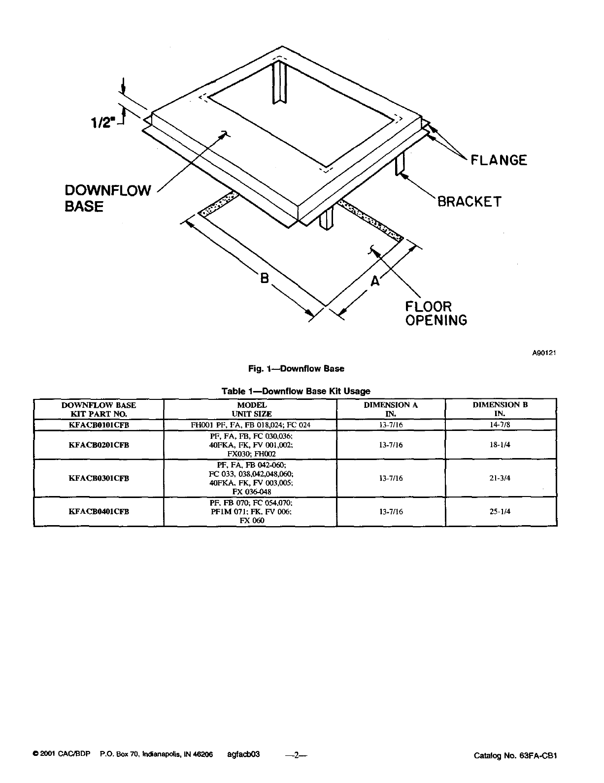
1. Cut ahole in floor large enough for clearance of downflow base brackets. See Fig. 1 and Table 1to determine clearance dimensions.
2. Set downflow base on floor with brackets inserted into hole.
3. Fasten base firmly to floor with screws through base flanges.
4. Set unit on downflow base in_g unit discharge duct flange through hole in base.
5. Connect ductwork to unit discharge duct flange.
Form: AG-FACB-03 Cancels: AG-FACB-02 Pdnted in U.S.A. 2-01 Catalog No. 63FA-CB1
112'
DOWNFLOW
BASE
FLANGE
'BRACKET
\
FLOOR
OPENING
Fig. 1--Downflow Base
Table 1--Downflow Base Kit Usage
DOWNFLOW BASE MODEL DIMENSION A DIMENSION B
KIT PART NO. UNIT SIZE IN. IN.
KFACB0101CFB FI-1001 PF, FA, FB 018,024; FC 024 13-7/16 14-7/8
PF, FA, FB, FC 030,036;
KFACB0201CFB 40FKA, FI,LFV 001,002; 13-7/16 18-1/4
FX030; FH002
PF, FA, FB 0424)60;
KFACB0301CFB FC 033, 038,042,048,060; 13-7/16 21-3/4
40FKA, FK, FV 003,005;
FX 0364)48
PF, FB 070; FC 034,070;
KFACB0401CFB PF1M 071; FK, FV 006; 13-7/16 25-1/4
FX060
A90121
0 2001 CAC/BDP P.O. Box 70, Indianapolis, IN 46206 agfacb03 --2-- Catalog No. 63FA-CB1
