CARRIER Evaporator Coils Manual L0211037
User Manual: CARRIER CARRIER Evaporator Coils Manual CARRIER Evaporator Coils Owner's Manual, CARRIER Evaporator Coils installation guides
Open the PDF directly: View PDF ![]() .
.
Page Count: 8
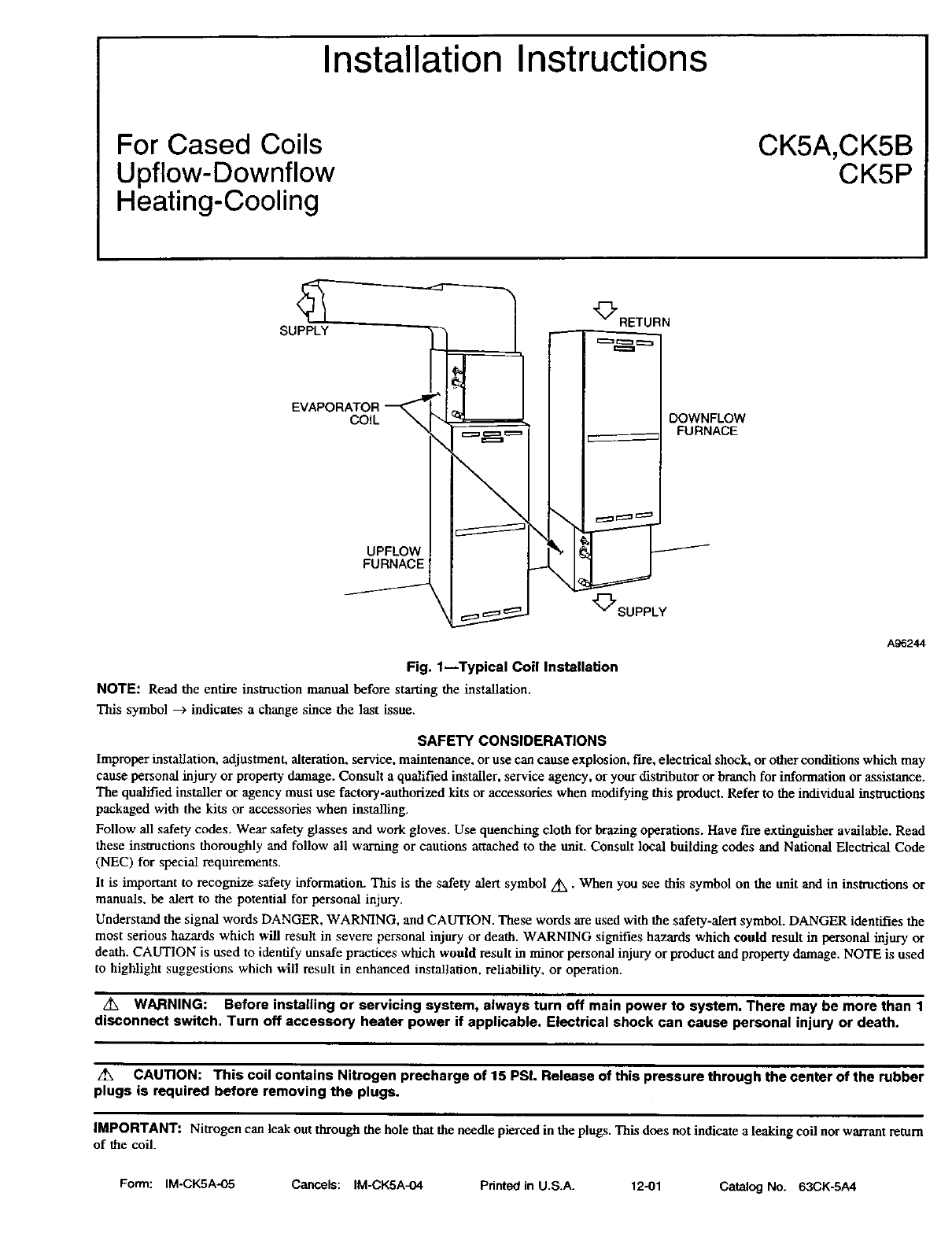
Installation Instructions
For Cased Coils
Upflow-Downflow
Heating-Cooling
CK5A,CK5B
CK5P
SUPPLY
EVAPORATOR_ -'_41
COIL_
UPFLOW
FURNACE
/
_RETURN
_SUPPLY
DOWNFLOW
FURNACE
/
Fig. 1--Typical Coil Installation
NOTE: Read the entire instruction manual before starting the installation.
This symbol --_ indicates a change since the last issue.
A_2_
SAFETY CONSIDERATIONS
Improper installation, adjustment, alteration, service, maintenance, or use can cause explosion, fire, electrical shock, or other conditions which may
cause personal injury or property damage. Consult a qualified installer, service agency, or your distributor or branch for information or assistance.
The qualified installer or agency must use factory-authorized kits or accessories when modifying this product. Refer to the individual instructions
packaged with the kits or accessories when installing.
Follow all safety codes. Wear safety glasses and work gloves. Use quenching cloth for brazing operations. Have fire extinguisher available. Read
these instructions thoroughly and follow all warning or cautions attached to the unit. Consult local building codes and National Electrical Code
(NEC) for special requirements.
It is important to recognize safety information. This is the safety alert symbol A,, • When you see this symbol on the unit and in instructions or
manuals, be alert to the potential for personal injury.
Understand the signal words DANGER, WARNING, and CAUTION. These words are used with the safety-alert symbol. DANGER identifies the
most serious hazards which will result in severe personal injury or death. WARNING signifies hazards which could result in personal injury or
death. CAUTION is used to identify unsafe practices which would result in minor personal injury or product and property damage. NOTE is used
to highlight suggestions which will result in enhanced installation, reliability, or operation.
WARNING: Before installing or servicing system, always turn off main power to system. There may be more than 1
disconnect switch. Turn off accessory heater power if applicable. Electrical shock can cause personal injury or death.
Z_x CAUTION: This coil contains Nitrogen precharge of 15 PSI. Release of this pressure through the center of the rubber
plugs is required before removing the plugs.
IMPORTANT: Nitrogen can leak out through the hole that the needle pierced in the plugs. This does not indicate a leaking coil nor warrant return
of the coil.
Form: IM-CK5A-05 Cancels: IM-CK5A-04 Pdnted in U.S.A. 12-01 Catalog No. 63CK-5A4
Table 1---CK5A/CK5B/CK5P Dimensions
MODEL NUMBER
*CK_A,B,P)XA018014
*CKS(A,B,P)XA024014
*CKS(A,BJ')XA030014
*CK5(A,B,P)XT036017
CKS(A,B,P)XW024017
CK5(A,B,P)XW030017
*CKS(A,B,PiXA036017
CKS(A,B,P)XE042017
*CKE(A,B,P)XT04202 I
*CKS(A,B,P)XT048021
CKS(A,B..P)XW036021
*CKS(A,B.PlXA042021
*CKS(A,B,P)XA048021
*C KS(A,B,P)XT060024
_CKS(A,B_P)XW048024
*CKS(A,B,PlXA060024
CKS(A,B,P)XX060024
TONNAGE
1_1/2
2
2-1_
3
2
2-1/2
3
3-1/2
3-1/2
4
3
3-1/2
4
5
4
5
5
METERING DEVICE
CK5A/B CK5P
Piston NUMBER TXV NUMBER
52 EA36YDI24
59 EA36YDI24
67 EA36YDI34
70 EA36YD144
59 EA36YDI24
67 EA36YDI34
70 EA36YDI44
78 EA36YDI44
78 EA36YDI44
84 EA36YDI54
70 EA36YDI44
78 EA36YDI44
84 EA36YDI54
90 EA36YDI54
84 EA36YDI54
90 EA36YDI54
90 EA36YDI54
FLUSH FIT
TO FURNACE
WIDTH (IN.)
14-3/16
14-3/16
14-3/16
17-1/2-
17-1/2
17-1/2
17-1/2
1%1/2
21
21
21
21
21
24-1/2
24-1/2
24-1/2
24-1/2
SHELF WIDTH
(SEE FIG. 3,
DIM A)
12-7/8
16-3/16
1%5/8
23-1/8
FITS NEXT SMALLER FURNACE
Equal Overhang Offset
with
Overhang Transition Left
X -- __
-- X X
-- X X
-- X X
-- X X
X -- __
X -- __
-- X X
-- X X
-- X X
X-- --
-- X X
-- X X
-- X X
INTRODUCTION
Use this instruction manual to install indoor coils on upflow or downflow furnaces. (See Fig. 1.) Do not install coil in horizontal position. Model
CK5A is enclosed in a painted casing while CK5B is available in an embossed casing; both of these coils come with pistons and both may be used
with R-22 systems or Puron®. The CKAP coil is enclosed in a painted casing, however, it has a Puron TXV so it is only compatible with Puron
systems.
INSTALLATION
PROCEDURE 1--INSPECT EQUIPMENT
File claim with shipper if equipment is damaged.
PROCEDURE 2---SELECT INSTALLATION PROCEDURE
NOTE: Installing coils rotated 90 degrees from the front of the furnace, in upflow or downflow applicadous, can cause water blow-off or coil
freeze-up due to the concentration of air on one slab of the ceil or lack of air to a slab in the coil. It is recommended that on this type of application,
a field-supplied adapter be placed between the coil and furnace to allow air to distribute properly between all slabs of the coil.
For cased coils in upflow applications, follow A. See Table I for dimensions and overhang options. Note instructions for placement of ceil casing
on fitrnace.
For cased coils in downflow applications, follow B.
For uncased coils in upflow applications, follow C.
PROCEDURE 3_INSTALLATION OF FURNACE COILS
A. Upflow Cased Coil Installation
1. Set coil in place on upflow furnace discharge air opening. (See Fig. 1.)
2. When coil front width matches furnace front width, die ceil can be placed direcdy on furnace.
NOTE: When model T036, T042, T048, or T060 is applied to same width furnace, remove block-off plates at casing base by removing 2 screws
per plate from side of casing. (See Fig. 8.)
3. Ensure coil is level for proper condensate drainage. Do not tip coil toward condensate drain. Coil enclosure need not be fastened or screwed
to furnace.
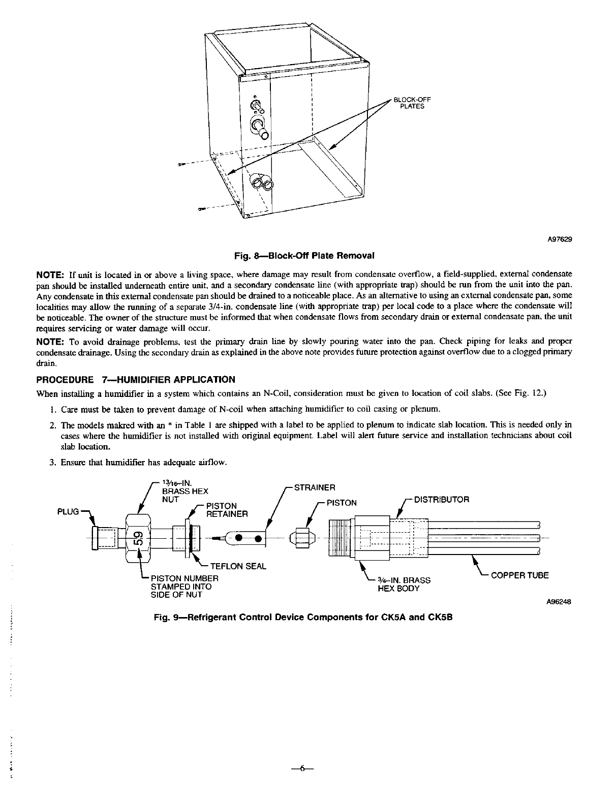
4. Following are instructions for alternative ways of overhanging coil on furnace: (See Fig. 7A, B, C.)
T MODEL (6TH DIGIT) COILS APPLIED CENTERED OVER NARROW FURNACE
1. There is no transition required for this application.
2. Remove coil from packaging and place on top of furnace with 1-5/8 in. overhang on both sides. (See Fig. 7A.)
3. Continue with normal installation practices. (See Procedure 4.)
A, W, OR X MODEL (6TH DIGIT) COIL APPLIED CENTERED OVER NARROW FURNACE WITH 2-1/4-1N. MINIMUM TRANSITION
1. Prepare transition, following recommended transition drawing. (See Fig. 5.) Fabricate a 2-1/4-in. tall (minimum) transition.
2. Place transition on top of gas furnace. (See Fig. 7B.) Secure with sheet metal screws. Place cell on top of transition. Make sure coil rests
evenly on top of transition and gas furnace.
3. Secure ceil to transition using sheet metal screws.
--2
I
193/16 "
__ /_i'_ __ F__EELDuSMuPPLIED
I
COIL
SUPPORT
[\\
3" MIN. _/
FURNACE _ "B" I
TABLE 1
_'-FURNACE
A01482
Fig. 2iTransition Required for Overhang
Except for "T" Coils (See Fig. 7)
A01_3
Fig. 3---Correct Orientation of Coil Suppo_ on Furnace
CAUTION
AIR CONDITIONING COIL BEHIND THIS
PANEL.DO NOT DRILL OR CUT PANEL
UNTILCOIL LOCATION HAS BEEN
VERIFIED BY REMOVING ACCESS
COVER.
A96359
Fig. 4---Plenum Caution Label
4. Continue with normal installation practices. (See Procedure4.)
NOTE: If cod (cased or uncased) is not being instaned in the standard orientation (front of coil matching front of furnace) then coil must be raised
2-I/4 in. above furnace.
A, W, OR X MODEL (6TH DIGIT) COIL APPLIED DIRECTLY ON TOP AND OFFSET TO THE LEFT ON NARROW FURNACE
1. Notch support rail on underside of coil cabinet to provide clearances for gas furnace flange. This rail is not visible from front of coil. To
locate position of notch, place coil directly on top of gas furnace with overhanging portion entirely on left side as in Fig. 7C. Mark location
of gas inmace flange on coil casing. Remove coil from top of furnace. Using tin snips, make a notch in rail large enough to allow clearance
for gas flow furnace flange.
2. Place coil on top of gas furnace. Make sure coil is shifted completely to left side, and notch is sufficient so coil rests on top of furnace
cabinet.
3. Prepare and install block-off plate. (See Fig. 7C.) Using field-supplied sheet metal, cut a block-off plate to be attached to bottom left side
of coil casing. This plate prevents air leakage from overhanging portion of coil. Attach plate using sheet metal screws.
4. Continue with normal installation practices. (See Procedure 4.)
B. Downflow Cased Coil Installation
1. Place N-coil on supply duct opening.
2. When coil width matches furnace width, furnace can be placed directly on the cased coil.
NOTI:: In' downflow installation with a 4-way multipoise furnace, break off perforated duct flanges on furnace. (See Furnace Installation
Instructions.)
3. Coils that underhang (narrower than furnace) must have a 2-l/4-in. long (minimum) field-fabricated Iransition between furnace and N-coil
casing.
4. Coils that overhang (wider than furnace) do not require a a'ansition in downflow application. However, a field-supplied furnace shelf should
be constructed to fit furnace to coil opening.
5. Place furnace on top of N-coil casing, or field-supplied furnace shelf.
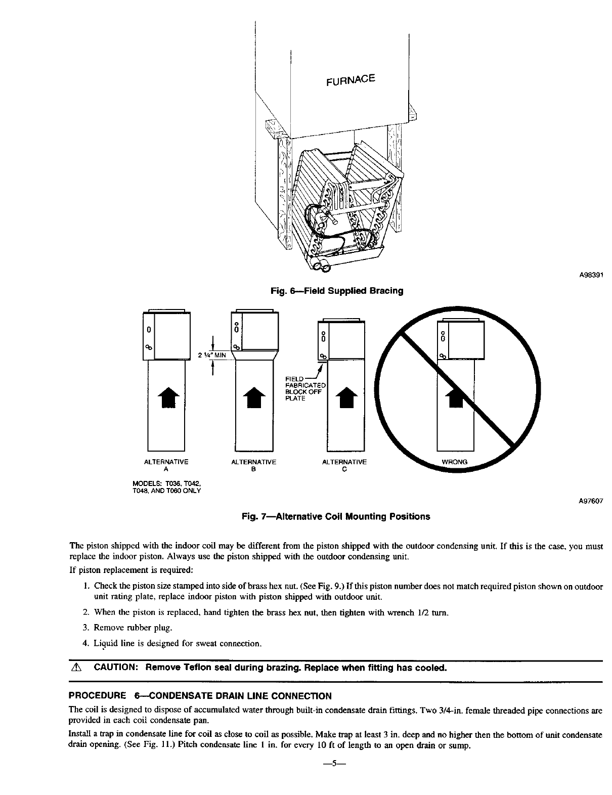
NOTE: When removing a coil from its casing in the downflow position, support the coil enclosure with field supplied bracing. (See Fig. 6.)
I3I
COIL CASINO WIDTH
B
REAR BRACKET
19 I_-
(OUTSIDE)
3/4_
FLANGES
SHOWN)
NOTE: WELD (3) PLACES
IN (41 CORNERS
I
(INSIDE OPENING)
FURNACE OUTLET
A
12-3/4
16-U16
19-9116
Dimensions (In.)
Fig, 5_Recommended Transition
A97232
"I
17-1/2
21
24-1/2
C. Upflow Uncased Coil Installation
Only the coils marked with an asterisk (*) on Table 1 can be used as an uncased application. In these models the coil can be removed from the
casing and installed as an uncased coil without need to field-fabricate a coil enclosure to prevent air bypass.
1. Field fabricate coil support shelf using dimensions given in Fig. 3. The coil support shelf is required to complete the uncased installation.
2. Locate and install the coil support shelf above furnace duct flanges, the coil support shelf is designed to accommodate upflow furnace
opening flanges.
3. Set coil in place.
4. Place plenum enclosure on furnace.
5. Insulate plenum enclosure.
6. Affix caution label to the right side of plenum enclosure. (See Fig. 4.) The caution label is stapled to the Installation Instructions.
7. Continue with normal installation practices. (See Procedure 4.)
PROCEDURE 4---CONNECT REFRIGERANT PIPING
Use accessory tubing package or field-supplied tubing of refrigerant grade. Suction tube must be insulated. Do not use damaged, dirty, or
contaminated tubing because it may plug refrigerant flow-control device. ALWAYS evacuate the coil and field-supplied tubing before opening
outdoor unit service valves.
PROCEDURE 5--CONNECT REFRIGERANT LIQUID AND SUCTION LINES
For matched and mismatched systems, use line sizes recommended in outdoor unit Installation Instructions.
The coil can be connected to outdoor units using accessory tubing packages or field-supplied tubing of refrigerant grade. Always evacuate tubing
and reclaim refrigerant when making connections or flaring tubing. Leak check connections before insulating entire suction line.
SUCTION LINE
Suction line is designed for field sweat connection. Line is plugged to keep out moisture and dirt. Remove these plugs only when ready to make
connection.
LIQUID LINE
CAUTION: To avoid damage to the refrigerant control device while brazing, wrap tubing or fittings with aheat-sinking
material such as a wet cloth.
A. The following section applies to only CK5A and CKSB coils:
SYSTEM REFRIGERANT CONTROL
z_x CAUTION: If unit is to be installed on system with a thermostatic expansion valve, removal of indoor coil piston is
required.
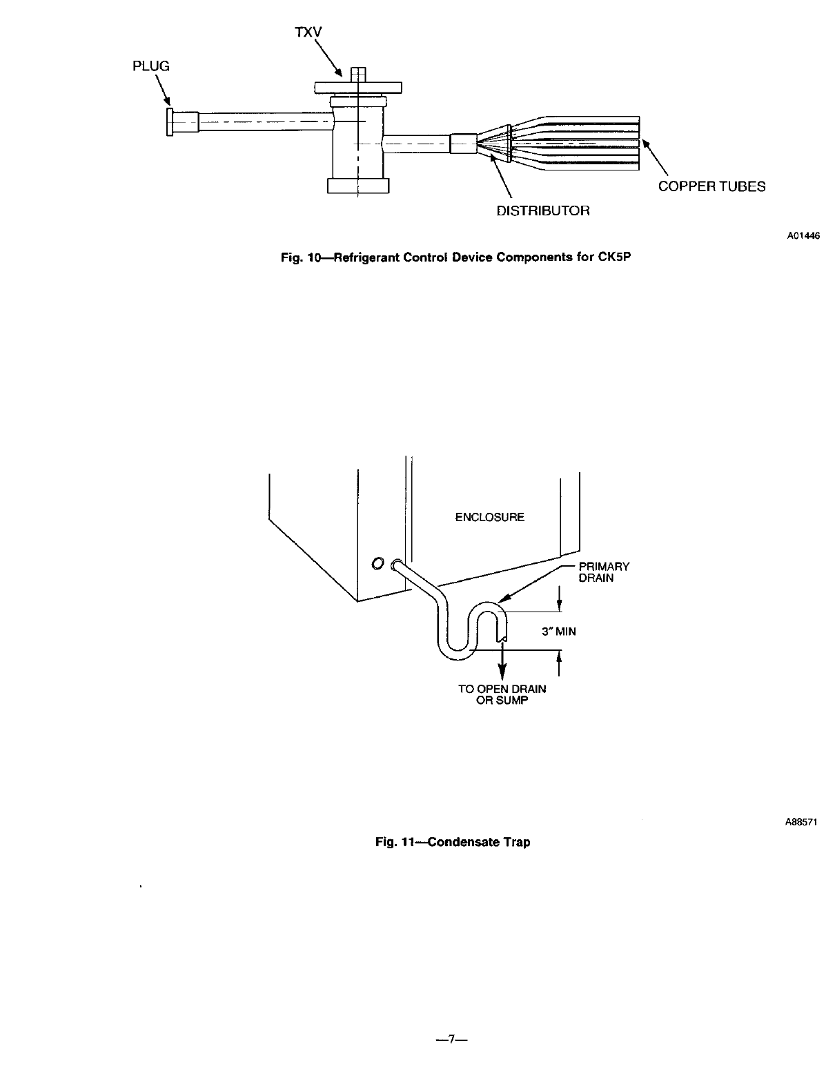
A refrigerant control device (bypass type piston) is factory supplied with coil. (See Table 1.) The piston has arefrigerant metering hole through
it, and is field replaceable.
\
\
FURNACE
m
2 1/4" MIN
f
1
Fig. 6--Field Supplied Bracing
o
o
FIE_ J
FABRICATED
BLOCK OFF
PLATE
m i m
ALTERNATIVE ALTERNATIVE ALTERNATIVE
A B C
MODELS: T036, T042,
T048, AND TO60 ONLY
Fig. 7--Alternative Coil Mounting Positions
WRONG
Ag83gt
A97607
The piston shipped with the indoor coil may be different from the piston shipped with the outdoor condensing unit. If this is the case, you must
replace the indoor piston. Always use the piston shipped with the outdoor condensing unit.
If piston replacement is required:
1. Check the piston size stamped into side of brass hex nut. (See Fig. 9.) If this piston number does not match required piston shown on outdoor
unit rating plate, replace indoor piston with piston shipped with outdoor unit.
2. When the piston is replaced, hand tighten the brass hex nut, then tighten with wrench 1/2 turn.
3. Remove rubber plug.
4. Li,qnid line is designed for sweat connection.
/f_ CAUTION: Remove Teflon seal during brazing. Replace when fitting has cooled.
PROCEDURE 6--CONDENSATE DRAIN UNE CONNECTION
The coil is designed to dispose of accumulated water through built-in condensate drain fittings. Two 3/4-in. female threaded pipe connections are
provided in each coil condensate pan.
Install a trap in condensate line for coil as close to coil as possible. Make trap at least 3 in. deep and no higher then the bottom of unit condensate
drain opening. (See Fig. 11.) Pitch condensate line 1 in. for every 10 ft of length to an open drain or sump.
m5m
PLATES
A97629
Fig. 8---Block-Off Plate Removal
NOTE: If unit is located in or above a riving space, where damage may result from condensate overflow, afield-supplied, external condensate
pan should be installed underneath entire unit, and a secondary condensate line (with appropriate trap) should be run from the unit into the pan.
Any condensate in this external condensate pan should be drained to a noticeable place. As an alternative to using an external condensate pan, some
localities may allow the atoning of a separate 3/4-in. condensate line (with appropriate trap) per local code to a place where the condensate will
be noticeable. The owner of the structure must be informed that when condensate flows from secondary drain or external condensate pan, the unit
requires servicing or water damage will occur.
NOTE: To avoid drainage problems, test the primary drain line by slowly pouring water into the pan. Check piping for leaks and proper
condensate drainage. Using the secondary drain as explained in the above note provides future protection against overflow due to a clogged primary
drain.
PROCEDURE 7--HUMIDIFIER APPLICATION
When installing a humidifier in a system which contains an N-Coil, consideration must be given to location of coil slabs. (See Fig. 12.)
I. Care must be taken to prevent damage of N-coil when attaching humidifier to coil casing or plenum•
2. The models makred with an * in Table 1 are shipped with a labet to be applied to plenum to indicate slab location• This is needed only in
cases where the humidifier is not installed with original equipment. Label will alert future service and installation technicians about coil
slab location.
3. Ensure that humidifier has adequate airflow.
PLUG_
13/16--IN•
_'- BRASS HEX /-- STRAINER
!NUT /PISTON ,-- DISTRIBUTOR
'J-- PISTON / /'-- ,/
• COPPER TUBE
STAMPED INTO HEX BODY
SIDE OF NUT A96248
Fig. 9---Refrigerant Control Device Components for CK5A and CK5B
i,
PLUG
\D-
TXV
DISTRIBUTOR
Fig. 10_Refrigerant Control Device Components for CK5P
A01446
ENCLOSURE
DRAIN
3" MIN
f
TO OPEN DRAIN
OR SUMP
Fig. 11--Condensate Trap
A88571
--7--
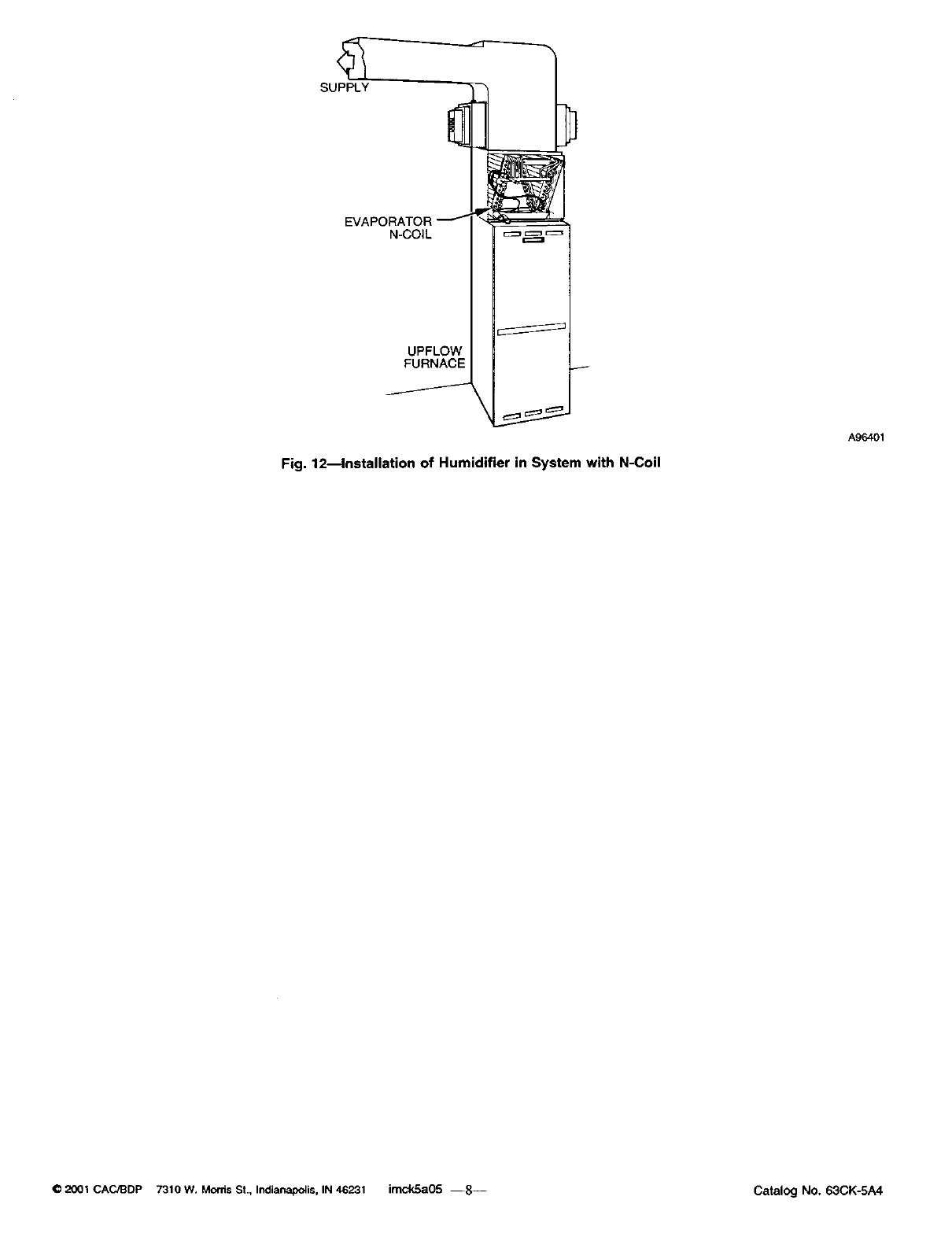
Fig. 12_lnstallation of Humidifier in System with N-Coil
A9_01
O2001 CAC/BDP 7310 w. Morris St., Indianapolis, IN 46231 imckSa05 --8-- Catalog NO. 63CK-SA4
