CARRIER Evaporator Coils Manual L0211039
User Manual: CARRIER CARRIER Evaporator Coils Manual CARRIER Evaporator Coils Owner's Manual, CARRIER Evaporator Coils installation guides
Open the PDF directly: View PDF ![]() .
.
Page Count: 4
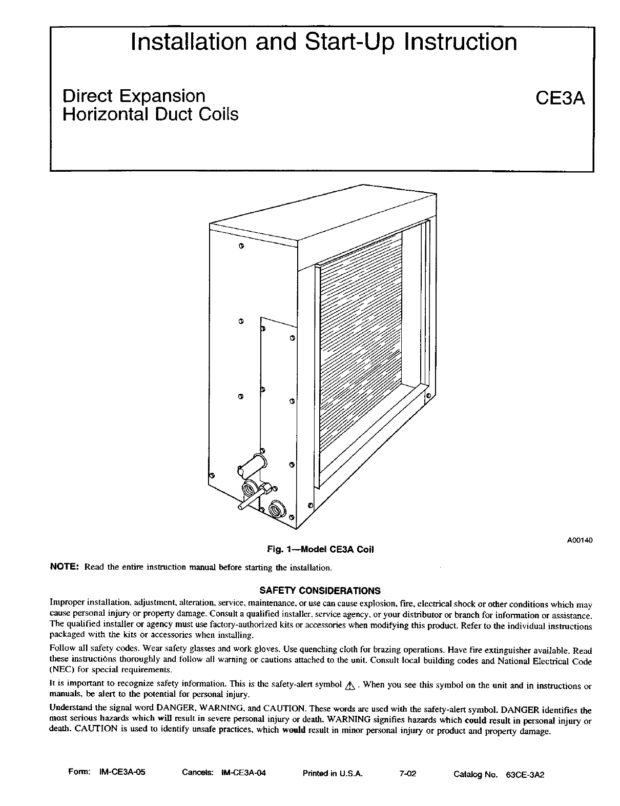
Installation and Start-Up Instruction
Direct Expansion
Horizontal Duct Coils CE3A
/
Fig. 1---Model CE3A Coil
NOTE: Read the entire instruction manual before starting the installation.
A_I_
SAFETY CONSIDERATIONS
Improper installation, adjustment, alteration, service, maintenance, or use can cause explosion, fire, electrical shock or other conditions which may
cause personal injury or property damage. Consult a qualified installer, service agency, or your distributor or branch for information or assistance.
The qualified installer or agency must use factory-authorized kits or accessories when modifying this product. Refer to the individual instructions
packaged with the kits or accessories when installing.
Follow all safety codes. Wear safety glasses and work gloves. Use quenching cloth for brazing operations. Have fire extinguisher available. Read
these instructions thoroughly and follow all warning or cautions attached to the unit. Consult local building codes and National Electrical Code
(NEC) for special requirements.
It is important to recognize safety information. This is the safety-alert symbol z_ - When you see this symbol on the unit and in instructions or
manuals, be alert to the potential for personal injury.
Understand the signal word DANGER, WARNING, and CAUTION. These words are used with the safety-alert symbol. DANGER identifies the
most serious hazards which will result in severe personal injury or death. WARNING signifies hazards which could result in personal injury or
death. CAUTION is used to identify unsafe practices, which would result in minor personal injury or product and property damage.
Form: IM-CE3A-05 Cancels: IM-CE3A-04 Pdnted in U.S.A. 7-02 Catalog No. 63CE-3A2
WARNING: Before installing or servicing system, always turn off main power to system. There may be more than one
disconnect switch. Turn off accessory heater power, if applicable. Electrical shock can cause personal injury or death.
CAUTION: This coil contains Nitrogen precharge of 15PSI. Release of this pressure through the center of the rubber
plugs is required before removing the plugs.
IMPORTANT: Nitrogen can leak out through the hole that the needle pierced in the plugs. This does not indicate leaking coil nor warrant return
of coil.
INSTALLATION
Use these instructions to install Model CE3A duct coil in horizontal position, (See Fig. 1.) Model CE3A duct coil is designed and tested to conform
to recommendations and standards established by Air Conditioning and Refrigeration Institute (ARI) Standard 210. It is easily adaptable to most
types of existing forced-air heating systems, or can be installed in an independent air-cooling system.
PROCEDURE 1--CHECK EXISTING DUCTWORK
Inspect the previously installed air distribution system for heating, to determine its suitability for cooling. Existing heating ductwork may have to
be modified and insulated to provide better air distribution for cooling.
PROCEDURE 2--INSULATE AND VAPORPROOF DUCT
Externally insulated ductwork must have an adequate vapor seal for summer operation. This is particularly important where the duct is exposed
to high humidity conditions in attics, vented crawl spaces, unconditioned basements and utility rooms. The vapor seal prevents condensation in
the insulating material and subsequent loss of insulating value. Properly installed heating supply ducts should already have adequate insulation
against excessive heat loss. This same insulation should, therefore, be satisfactory in the summer for protection against heat gain. However,
depending on the specific installation, it may be desirable to add to the insulation.
PROCEDURE 3--INSTALL COIL IN SUPPLY AIR DUCT
1. When the connecting air supply duct is smaller than the coil inlet opening, construct transition piece so that vertical and horizontal
dimensions of transition piece do not increase more than 30° angle. If connecting outlet duct is smaller than outlet opening of coil, limit
transition to maximum of 45° angle.
2. Provide at least 3ft of straight duetwork preceding coil inlet.
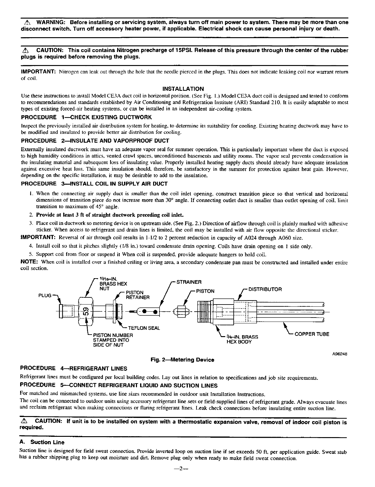
3. Place coil in ductwork so metering device is on upstream side. (See Fig. 2.) Direction of airflow through coil is plainly marked with adhesive
sticker. When access to refrigerant and drain lines is limited, the coil may be installed with air flow opposite the directional sticker.
IMPORTANT: Reversal of air through coil results in 1-1/2 to 2 percent reduction in capacity of A024 through A060 size.
4. Install coil so that it pitches slightly (1/8 in.) toward condensate drain opening. Coils have drain opening on 1 side only.
5. Support coil from floor or suspend it When coil is suspended, provide adequate hangers to hold coil.
NOTE: When coil is installed over a finished ceiling or living area, a secondary condensate pan must be constructed and installed under entire
coil section.
/,- l_he-IN.
BRASS HEX
NUT PISTON
PLUG _RETAINER
"- TEFLON SEAL
_-"PISTON NUMBER
STAMPED INTO
SIDE OF NUT
3/4-1N. BRASS
HEX BODY
_f
d
_-- COPPERTUBE
A_2_
Fig. 2--Metering Device
PROCEDURE 4--REFRIGERANT LINES
Refrigerant lines must be configured per local building codes. Lay out lines in relation to specifications and job site requirements.
PROCEDURE 5--CONNECT REFRIGERANT LIQUID AND SUCTION LINES
For matched and mismatched systems, use line sizes recommended in outdoor unit Installation Instructions.
The coil can be connected to outdoor units using accessory refrigerant line sets or field-supplied lines of refrigerant grade. Always evacuate lines
and reclaim refrigerant when making connections or flaring refrigerant lines. Leak check connections before insulating entire suction line.
CAUTION: If unit is to be installed on system with a thermostatic expansion valve, removal of indoor coil piston is
required.
A. Suction Line
Suction line is designed for field sweat connection. Provide inverted loop on suction line if set exceeds 50 ft, per application guide. Sweat stub
has a rubber shipping plug to keep out moisture and dirt. Remove plug only when ready to make field sweat connection.
--2--
CAUTION: To avoid damage while brazing, wrap tubing or fitting with a heat-sinking material, such a wet cloth.
B. Liquid Line
Liquid line is designed for sweat connection. During installation these steps should be followed:
1. Replace piston if required. Check piston size stamped into side of brass hex nut. (gee Fig. 2.) If piston number does not match required
piston shown on outdoor unit rating plate, replace indoor piston with piston shipped with outdoor unit.
2. When piston is replaced, finger tighten plus 1/4 turn.
CAUTION: Remove Teflon seal during brazing. Replace when fitting has cooled.
3. Liquid stub has a rubber shipping plug to keep out moisture and dirt. Remove plug only when ready to make field sweat connection.
Table 1--Refrigerant Metering Device
MODEL NUMBER TONNAGE METERING DEVICE
PISTON NUMBER
CE3AXA024000 2 59
CE3AXA030000 2-1/2 67
CE3AXA036000 370
CE3AXA042000 3-1/2 78
CE3AXA048000 4 84
CE3AXA0600_ 5 90
PROCEDURE 6_CONNECT CONDENSATE LINES
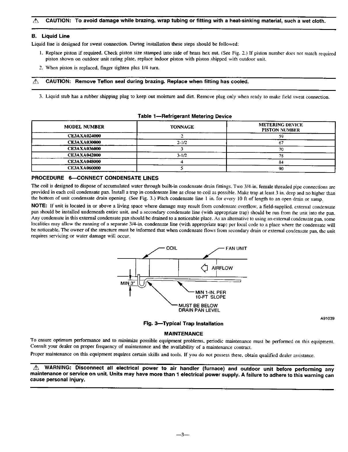
The coil is designed to dispose of accumulated water through built-in condensate drain fittings. Two 3/4-in. female threaded pipe connections are
provided in each coil condensate pan. Install a trap in condensate line as close to coil as possible. Make trap at least 3 in. deep and no higher than
the bottom of unit condensate drain opening. (See Fig. 3.) Pitch condensate line 1 in. for every 10 ft of length to an open drain or sump:
NOTE: If unit is located in or above a living space where damage may result from condensate overflow, a field-supplied, external condensate
pan should be installed underneath entire unit, and a secondary condensate line (with appropriate trap) should be run from the unit into the pan.
Any condensate in this external condensate pan should be drained to a noticeable place. As an alternative to using an external condensate pan, some
localities may allow the running of a separate 3/4-in. condensate line (with appropriate trap) per local code to a place where the condensate will
be noticeable. The owner of the structure must be informed that when condensate flows from secondary drain or external condensate pan, the unit
requires servicing or water damage will occur.
f COIL f FAN UNIT
<_ AIRFLOW
i
MIN _
MUST BE BELOW
DRAIN PAN LEVEL
A91039
Fig. 3_Typical Trap Installation
MAINTENANCE
To ensure optimum performance and to minimize possible equipment problems, periodic maintenance must be performed on this equipment.
Consult your dealer on proper frequency of maintenance and the availability of a maintenance contract.
Proper maintenance on this equipment requires certain skills and tools. If you do not possess these, obtain qualified dealer assistance.
/_ WARNING: Disconnect all electrical power to air handler (furnace) and outdoor unit before performing any
maintenance or service on unit. Units may have more than 1 electrical power supply. A failure to adhere to this warning can
cause personal injury.
m3__
Minimum maintenance should be performed on this equipment as follows:
1. Check and clean or replace air filter each month, or as required.
2. Check cooling coil, drain pan and condensate drain at start of each cooling season for cleanliness. Clean as needed.
NOTE: Because of possible damage to equipment, or personal injury, maintenance should be performed by qualified persons only.
WARNING: As with any mechanical equipment, personal injury can result from sharp metal edges, etc.; therefore, be
careful when removing parts.
A. Air Filter
An air filter is not provided ,x_an inte_ai part of this cooling coil. However, a field-supplied filter must be used upstream of the coil and must
be inspected frequently. When filter becomes clogged with dust or lint, it should be replaced (disposable type) or cleaned (cleanable type). Inspect
filter at least once each month, and replace or clean at least twice a year (more often if necessary).
NOTE: Do not operate coil without a filter in place in return-air duct. Always replace filter with same size and type filter.
_. WARNING: Before installing or servicing fan coil, always turn off all power to the unit. There may be more than 1
disconnect switch. Turn off accessory heater power if applicable. Electrical shock can cause personal injury or death.
B. Condensate Pan and Drain
Check drain pan and condensate drain at the same time cooling coil is checked. Clean drain pan and condensate drain thoroughly. Flush pan and
drain tube with clear water. If drain tube or trap is restricted, clean with high-pressure water. If this does not work, try a plumber's snake or similar
probe device. (See Fig. 3.)
C. Cleaning Coil
To gain access to coil, it may he necessary to cut a window in ductwork.
After cutting out section of ductwork and cleaning coil, cover opening with new, evenly cut piece of sheet metal and fasten in place with sheet
metal screws.
Coil is easily cleaned when dry. Therefore, check and clean coil before each cooling season. Inspect coil periodically during cooling season. If
coil is coated with dirt or lint, clean with a vacuum using soft brush attachment. BE CAREFUL NOT TO BEND COIL FINS. If coil is coated
with oil or grease, disconnect and remove coil from ductwork. Then, clean coil with mild detergent and water solution. Rinse with clear water.
D. Replacing or Cleaning Metering Device
The piston of the metering device shipped with coil is used for most applications. However, for reliable, full capacity operation, use piston shipped
with the outdoor unit in the indoor coil, if the piston in the indoor coil is different.
I. Pump down outdoor unit. Shut off service valves at condensing unit.
/_ WARNING: Be sure all electrical power to equipment is turned off. A failure to adhere to this warning can cause
personal injury.
2. Recover remaining refrigerant from tubing and coil through gage port on suction service valve.
3. Where required, remove front panel from coil casing.
4. Disconnect refrigerant liquid tube from metering device.
5. Using knife, pry off piston retainer (flare end of metering device).
6. Using small wire, pull out piston from body of metering device. (See Fig. 2.)
7. When cleaning piston, be careful not to scratch or enlarge opening, as this will affect operation.
8. Install new (or replace cleaned) piston in metering device body. There is no front or back to piston.
9. Install new piston retainer (because of probable damage done in initial removal).
10. Reconnect and tighten refrigerant tube.
NOTE: To avoid deforming metering body, causing piston to lodge in partially open or closed position, use a backup wrench and do not
overtighten.
1I. Pressurize tubing and coil, then check for leaks.
12. Purge or evacuate tubing and coil as necessary.
t:12002 CACt_DP 7310 W. Morris St.. Indianapolis, IN 46231 imce3a05 _Book/Tab: 1/3d,2/4d Catalog No. 63CE-3A2
