CARRIER Evaporator Coils Manual L0211040
User Manual: CARRIER CARRIER Evaporator Coils Manual CARRIER Evaporator Coils Owner's Manual, CARRIER Evaporator Coils installation guides
Open the PDF directly: View PDF ![]() .
.
Page Count: 8
Installation Instructions
Upflow--Downflow CC5A Uncased Coil
HeatingmCooling CD5A, CD5P Cased Coil
CC5A
CD5A/CD5P
U_ _"RETURN
s__)
EVAPORATOR
COIL _ • DOWNFLOW
FURNACE
UPFLOW IRI!/
_L__ _[_SUPPLY
A_2_
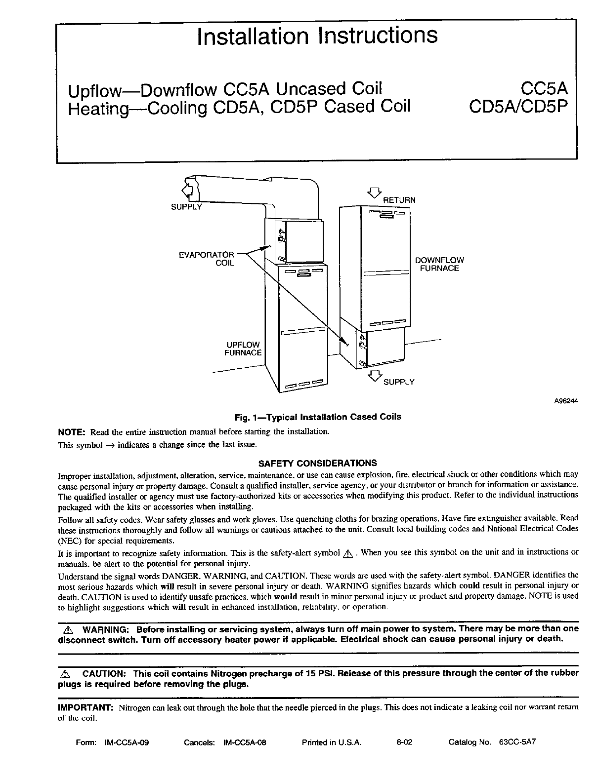
Fig. 1--Typical Installation Cased Coils
NOTE: Read the entire instruction manual before starfng the installation.
This symbol --) indicates a change since the last issue.
SAFETY CONSIDERATIONS
Improper installation, adjustment, alteration, service, maintenance, or use can cause explosion, t-_-e,electrical shock or other conditions which may
cause personal injury or property damage. Consult a qualified installer, service agency, or your distributor or branch for information or assistance.
The qualified installer or agency must use factory-authorized kits or accessories when modifying this product. Refer to the individual instructions
packaged with the kits or accessories when installing.
Follow all safety codes. Wear safety glasses and work gloves. Use quenching cloths for brazing operations. Have fire extinguisher available. Read
these instructions thoroughly and follow all warnings or cautions attached to the unit. Consult local building codes and National Electrical Codes
(NEC) for special requirements.
It is important to recognize safety information. This is the safety-alert symbol z_ • When you see this symbol on the unit and in instructions or
manuals, be alert to the potential for personal injury.
Understand the signal words DANGER, WARNING. and CAUTION. These words are used with the safety-alert symbol. DANGER identifies the
most serious hazards which will result in severe personal injury or death. WARNING signifies hazards which could result in personal injury or
death. CAUTION is used to identify unsafe practices, which would result in minor personal injury or product and property damage. NOTE is used
to highlight suggestions which will result in enhanced installation, reliability, or operation.
z_ WARNING: Before installing or servicing system, always turn off main power to system. There may be more than one
disconnect switch. Turn off accessory heater power if applicable. Electrical shock can cause personal injury or death.
Z_ CAUTION: This coil contains Nitrogen prscharge of 15 PSI. Release of this pressure through the center of the rubber
plugs is required before removing the plugs.
IMPORTANT: Nitrogen can leak out through the hole that the needle pierced in the plugs. This does not indicate a leaking coil nor warrant return
of the coil.
Form: IM-CC5A-09 Cancels: IM-CC5A-08 Pdnted in U.S.A. 8-02 Catalog No. 63CC-5A7
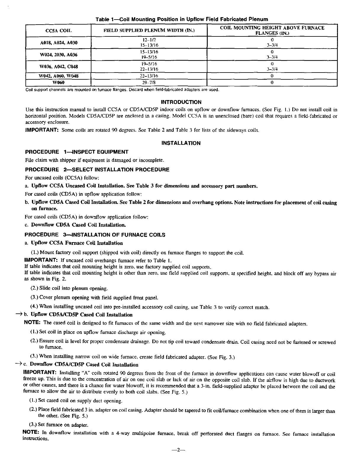
Table1_oil MountingPositioninUpflowFieldFabricatedPlenum
CCSA COIL FIELD SUPPLIED PLENUM WIDTH (IN./ COIL MOUNTING HEIGHT ABOVE FURNACE
FLANGES (IN.)
12-1/2 0
A018, A024, A030 15-13116 3-3/4
15-13/16 0
W024, 2030, A036 19-5/16 3-3/4
19-5/16 0
W036, A042, C048 2_13/16 3-3/4
W042, A060. W048 22-13/16 0
W060 29_/8 0
Coil supportchannelsare mountedon furnace flanges. DiSCardwhen field-fabncated adapters are used.
INTRODUCTION
Use this instruction manual to install CC5A or CD5A/CD5P indoor coils on upflow or downflow furnaces. (See Fig. 1.) Do net install coil in
horizontal position. Models CD5MCD5P are enclosed in a casing. Model CC5A is an unenclosed (bare) coil that requires a field-fabricated or
accessory enclosure.
IMPORTANT: Some coils are rotated 90 degrees. See Table 2 and Table 3 for lists of the sideways coils.
INSTALLATION
PROCEDURE 1--INSPECT EQUIPMENT
File claim with shipper ff equipment is damaged or incomplete.
PROCEDURE 2--SELECT INSTALLATION PROCEDURE
For uncased coils (CC5A) follow:
a. Upflow CC5A Uncased Coil Installation. See Table 3 for dimensions and accessory part numbers.
For cased coils (CD5A) in upflow application follow:
b. Upflow CD5A Cased Coil Installation. See Table 2 for dimensions and overhang options. Note instructions for placement of coil easing
on furnace.
For cased coils (CDSA) in downfiow application follow:
c. Dowrdlow CD5A Cased Coil Installation.
PROCEDURE 3---INSTALLATION OF FURNACE COILS
a. Upflow CC5A Furuace Coil Installation
(1.) Mount factory coil support (shipped with coil) directly on furnace flanges to support the coil.
IMPORTANT: If uncased coil overhangs furnace refer to Table 1.
If table indicates that coil mounting height is zero, use factory supplied coil supports.
If table indicates that coil mounting height is other than zero, use field supplied coil supports, at specified height, and block off any bypass air
as shown in Fig. 2.
(2.) Slide coil into plenum opening.
(3.) Cover plenum opening with field supplied front panel.
(4.) When installing uncased coil into pro-installed accessory coil casing, use Table 3 to verify correct match.
-"> b. Upflow CDSAJCD5P Cased Coil Installation
NOTE: The cased coil is designed to fit furnaces of the same width and the next narrower size with no field fabricated adapters.
(1.) Set coil in place on upfiow furnace discharge air opening.
(2.) Ensure coil is level for proper condensate drainage. Do not tip coil toward condensate drain. Coil casing need not be fastened or screwed
to furnace.
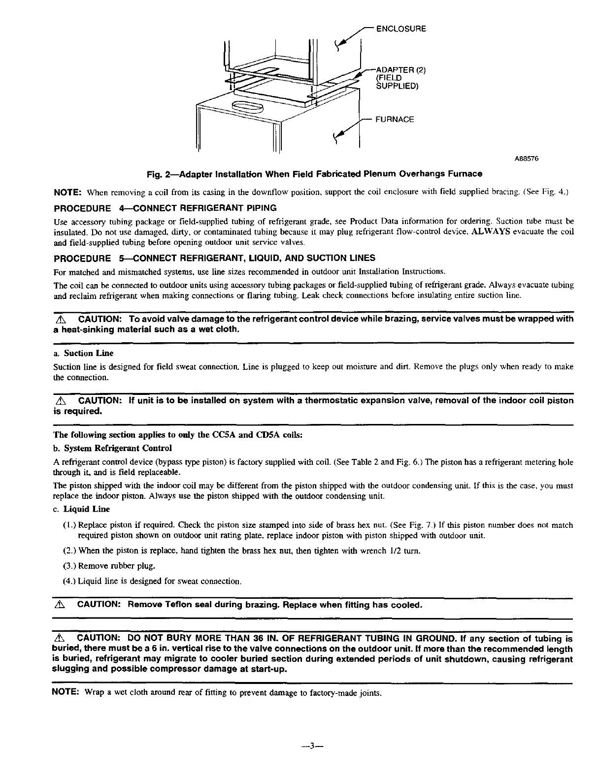
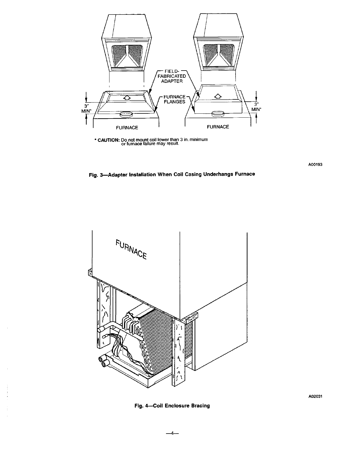
(3.) When installing narrow coil on wide furnace, create field fabricated adapter. (See Fig. 3.)
---> c. Downflow CD5A/CD5P Cased Coil Installation
IMPORTANT: Installing "A" coils rotated 90 degrees from the front of the furnace in downflow applications can cause water blowoff or coil
freeze up. This is due to the concentration of air on one coil slab or lack of air on the opposite coil slab. If the airflow is high due to ductwork
or other causes, and there is a chance for water blowoff, it is recommended that a 3-in. field-supplied adapter be placed between the coil and the
furnace to allow the air to distribute evenly to both coil slabs. (See Fig. 5,)
(1.) Set cased coil on supply duct opening.
(2.) Place field fabricated 3 in. adapter on coil casing. Adapter should be tapered to fit coil/furnace combination when one of them is larger than
the other. (See Fig. 5.)
(3.) Set furnace on adapter.
NOTE: In downflow installation with a4-way multipoise furnace, break off perforated duct flanges on furnace. See furnace installation
instructions.
2--
12)
(FIELD
SUPPLIED)
FURNACE
A88576
Fig. 2--Adapter Installation When Field Fabricated Plenum Overhangs Furnace
NOTE: When removing a coil from its casing in the downflow position, support the coil enclosure with field supplied bracing. (See Fig. 4.)
PROCEDURE 4_CONNECT REFRIGERANT PIPING
Use accessory tubing package or field-supplied tubing of refrigerant grade, see Product Data information for ordering. Suction tube must be
insulated. Do not use damaged, dirty, or contaminated tubing because it may plug refrigerant flow-control device. ALWAYS evacuate the coil
and field-supplied tubing before opening outdoor unit service valves.
PROCEDURE 5--CONNECT REFRIGERANT, LIQUID, AND SUCTION LINES
For matched and mismatched systems, use line sizes recommended in outdoor unit Installation Instructions.
The coil can be connected to outdoor units using accessory tubing packages or field-supplied tubing of refrigerant grade. Always evacuate tubing
and reclaim refrigerant when making connections or flaring tubing. Leak check connections before insulating entire suction line.
Z_X CAUTION: To avoid valve damage to the refrigerant control device while brazing, service valves must be wrapped with
a heat-sinking material such as a wet cloth.
a. Suction Line
Suction line is designed for field sweat comaection. Line is plugged to keep out moisture and dirt. Remove the plugs only when ready to make
the connection.
A_, CAUTION: If unit is to be installed on system with athermostatic expansion valve, removal of the indoor coil piston
is required.
The following section applies to only the CC5A and CD5A coils:
b, System Refrigerant Control
A refrigerant control device (bypass type piston) is factory supplied with coil. (See Table 2 and Fig. 6.) The piston has a refrigerant metering hole
through it, and is field replaceable.
The piston shipped with the indoor coil may be different from the piston shipped with the outdoor condensing unit. If this is the case, you must
replace the indoor piston. Always use the piston shipped with the outdoor condensing unit.
c. Liquid Line
(1.) Replace piston if required. Check the piston size stamped into side of brass hex nut. (See Fig. 73 If this piston number does not match
required piston shown on outdoor unit rating plate, replace indoor piston with piston shipped with outdoor unit.
(2.) When the piston is replace, hand tighten the brass hex nut, then tighten with wrench 1/2 turn.
(3.) Remove rubber plug.
(4.) Liquid line is designed for sweat connection.
CAUTION: Remove Teflon seal during brazing. Replace when fitting has cooled.
z_ CAUTION: DO NOT BURY MORE THAN 36 IN. OF REFRIGERANT TUBING IN GROUND. If any section of tubing is
buried, there must be a 6 in. vertical rise to the valve connections on the outdoor unit. If more than the recommended length
is buried, refrigerant may migrate to cooler buried section during extended periods of unit shutdown, causing refrigerant
slugging and possible compressor damage at start-up.
NOTE: Wrap a wet cloth around rear of fitting to prevent damage to factory-made joints.
--3--
i
MIN"
FURNACE
* CAUTION: Do not mount coil lower than 3 in. minimum
or furnace failure may result,
Fig. 3_Adapter Instaliation When Coil Casing Underhangs Furnace
A00193
Fig. 4--Coil Enclosure Bracing
A02031
MODEL NUMBER
CDSAXA018014
CDSAXA024014
CD5AXA030014
CDSAXW024017
CD5AXW030017
CDSAXA036017
CDSAXW036021
CDSAXA042021
CD5AXA048021
CD5AXC048021
*CDSAXW042024
*CD5AXW048024
*CD5AXA060024
*CD5AXW060031
*CDSPXX060024
*Sideways Coils
f
DOWNFLOW
FURNACE WITH
ADAPTER WHEN
REQUIRED
/
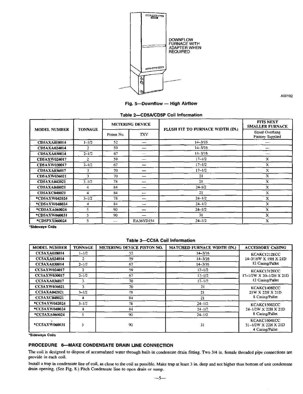
Fig. 5--Downflow -- High Airflow
Table 2----CD5A/CD5P Coil Information
METERING DEVICE
TONNAGE FLUSH NT TO
Pis_n No TXV
I-1/2
2
2-1/2
2
2-112
3
3
3 1/2
4
4
3-1/2
4
5
5
5
52
59
67
59
67
70
70
78
84
84
78
84
90
90
-- EA36YDI54
FURNACE WIDTH (IN,)
14-3/16
14-3/16
14-3/16
17-1/2
17-1/2
17-1/2
21
21
24-1/2
21
24-1!2
24-1/2
24-1/2
31
24-1/2
A00192
FITS NEXT
SMALLER FURNACE
Equal Ove_g
Fac_ Supplied
X
X
X
X
X
X
X
X
X
X
X
X
Table 3_CC5A Coil Information
MODEL NUMBER TONNAGE METERING DEVICE PISTON NO. MATCHED FURNACE WIDTH (IN.) ACCESSORY CASING
CCSAXA018014 1-1/2 52 14-3116 KCAKC 1212ECC
CCSAXA024014 2 59 14-3/16 14-3/16W X 19H X 21D
CCSAXA030014 2-1/2 67 14-3/16 12 Ca.sing/Pallet
CC$AXW024017 2 59 17-1/2 KCAKCI312ECC
CCSAXW030017 2-1/2 67 17-1/2 17-1/2W X 20-1!2H X 21D
CCSAXA036017 370 17-1/2 12 Caging/Pallet
CCSAXW036021 3 70 21 KCAKC 1408ECC
CU5AXA042021 3-1/2 78 21 21W X 22H X 21D
CUSAXC048021 4 84 21 8 Casing/Pallet
*CCSAXW042024 3-1_ 78 24-1/2 KCAKC 1508ECC
*CCSAXW048024 4 84 24-1/2 24-I_W X 22H X 21D
*CCSAXA060024 5 90 24-1/2 8 Ca._ing/Pallet
,KCAKC 1604ECC
*CCSAXW060031 5 q0 31 31-1/2W X 22H X 21D
4 C_ing/Pallet
*Sideways Coils
PROCEDURE 6--MAKE CONDENSATE DRAIN LINE CONNECTION
The coil is designed to dispose of accumulated water through built-in condensate drain fitting. Two 3/4 in. female threaded pipe connections are
provide in each coil.
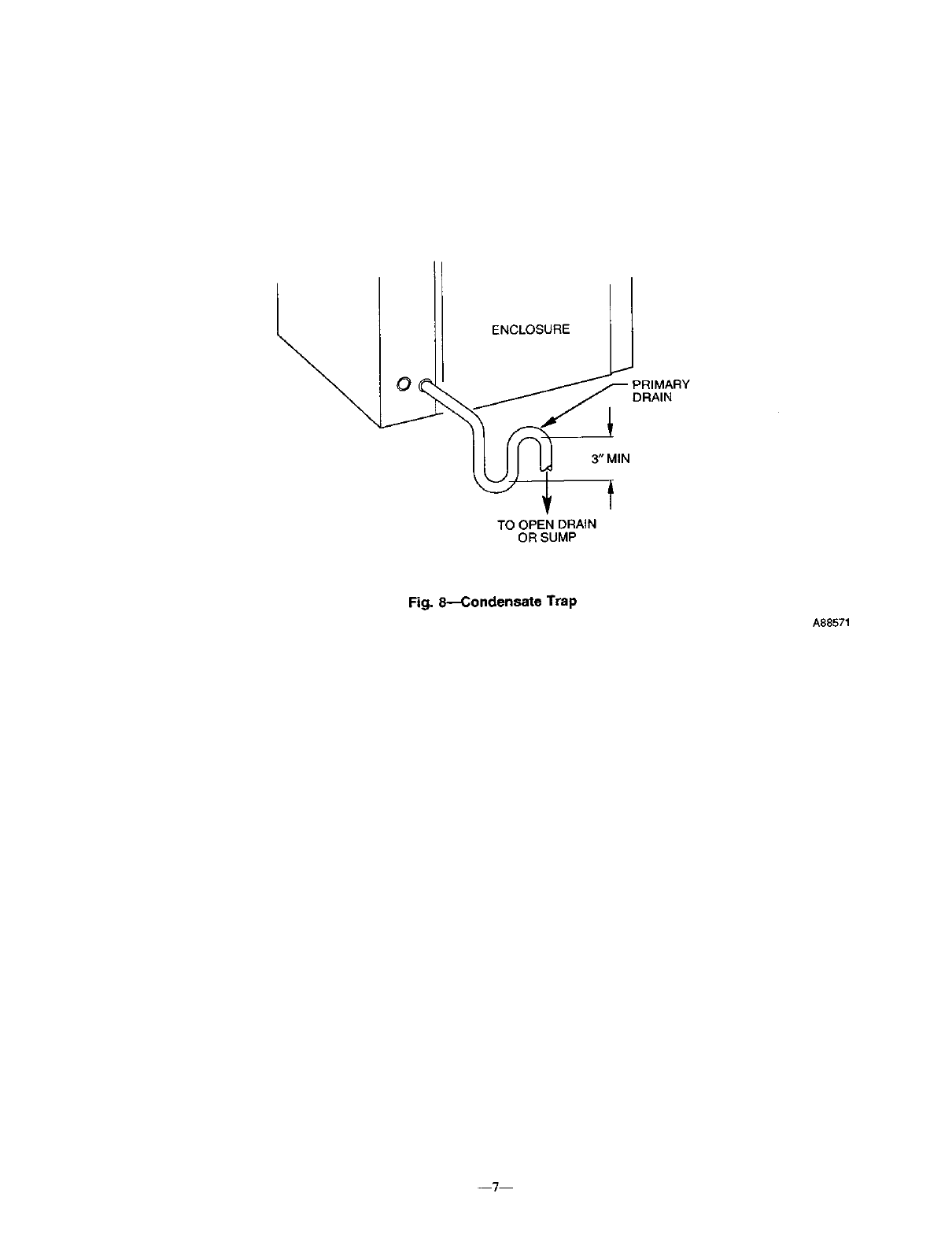
Install a trap in condensate line of coil, as close to die coil as possible. Make trap at least 3 in. deep and not higher than bottom of unit condensate
drain opening. (See Fig. 8.) Pitch Condensate line to open drain or sump.
--5 m
PLUG
13/16-1N.
'-BRASS HEX /-- STRAINER
/NUT /p,_,T,-_,, s-- DISTRIBUTOR
j-- PISTON /jr- io _l,_ ,[
\
STAMPED INTO HEX BODY
SIDE OF NUT
--+
COPPERTUBE
A96248
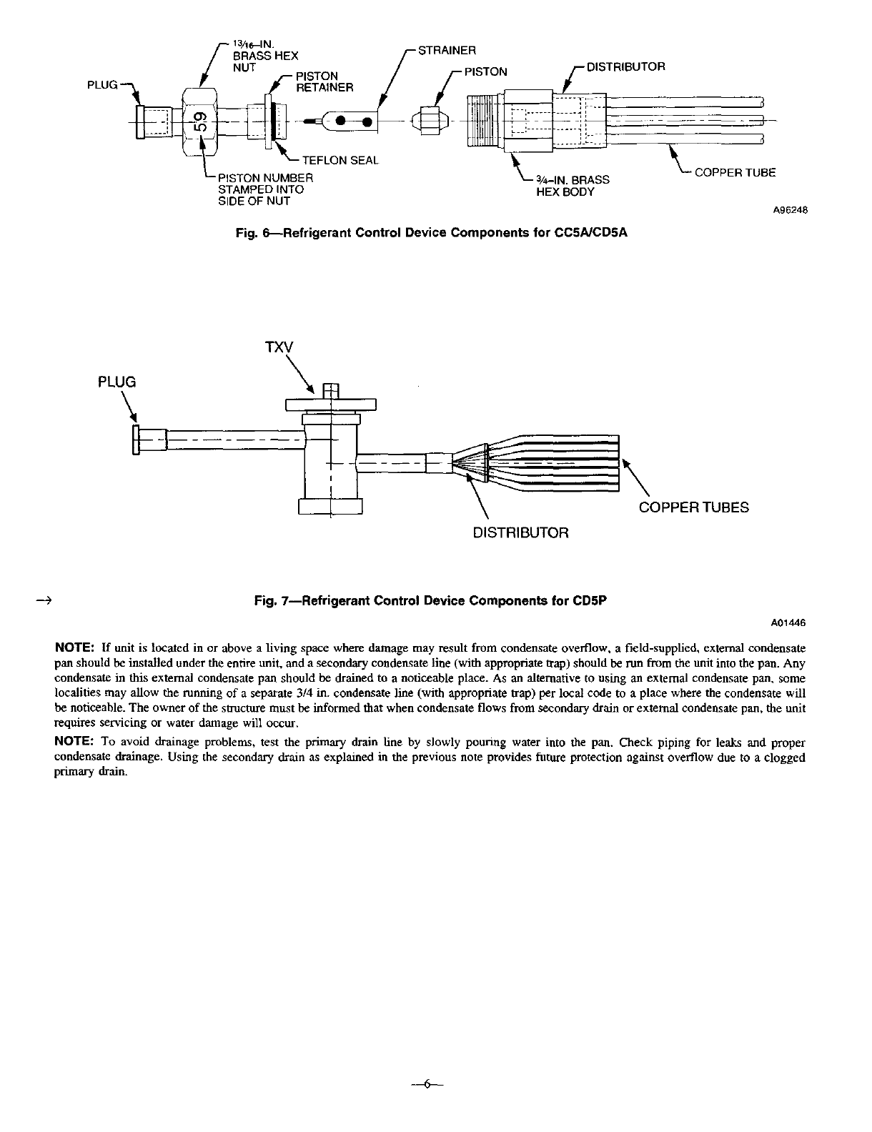
Fig. 6_Refrigerant Control Device Components for CC5A/CDSA
PLUG
\B
TXV
I
_-- - -- _COPPER TUBES
DISTRIBUTOR
-..) Fig. 7--Refrigerant Control Device Components for CD5P
A01446
NOTE: If unit is located in or above a living space where damage may result from condensate overflow, a field-supplied, external condensate
pan should be installed under the entire unit, and a secondary condertsate line (with appropriate trap) should be rtm from the unit into the pan. Any
condensate in this external condensate pan should be drained to a noticeable place. As an alternative to using an external condensate pan, some
localities may allow the running of a separate 3/4 in. condensate line (with appropriate trap) per local code to a place where the condensate will
be noticeable. The owner of the structure must be informed that when condensate flows from secondary drain or external condensate pan, the unit
requires servicing or water damage will occur.
NOTE: To avoid drainage problems, test the primary drain line by slowly pouring water into the pan. Check piping for leaks and proper
condensate drainage. Using the secondary drain as explained in the previous note provides future protection against overflow due to a clogged
primary drain.
-Jo--
ENCLOSURE
DRAIN
3" MIN
t
TO OPEN DRAIN
OR SUMP
Fig. 8--Condensate Trap
A88571
--?--

O2002 CAC/BDP 7310 w+ Mords St., IndianapOlis, IN 46231 imccSa09 --8-- Catalog No. 63CC-5A7
