CARRIER Controls And HVAC Accessories Manual L0410523
User Manual: CARRIER CARRIER Controls and HVAC Accessories Manual CARRIER Controls and HVAC Accessories Owner's Manual, CARRIER Controls and HVAC Accessories installation guides
Open the PDF directly: View PDF ![]() .
.
Page Count: 8
System Pilot
Owner's Manual
Part Number 33PILOT-01
CONTENTS
Page
SAFETY CONSIDERATIONS ...................... l
GENERAL ........................................ l
OPERATION .................................... 1-7
Power-Up Display ................................ 1
OAT Display ...................................... 2
User Interface .................................... 2
Timeout Feature .................................. 3
Program Mode ................................... 3
•ATTACH
•CTLR-ID
• ALARM HIST
• TIME/DATE
• CONFIG TABLES
• SCHEDULE
• DETACH
Modifying Set Points ............................. 6
Occupancy Override ............................. 6
Alternate Maintenance Table ..................... 6
Bus Scan ......................................... 7
Holiday Configuration Table ...................... 7
external device that does not have a custom Default screen, the
System Pilot reads that device's first status table and displays it
as the Default screen.
DEFAULT DEVICE DESIGNATION -- If the System Pi-
lot is connected to a local bus of a VVT® zone controller
(Comm2), the default device is the local zone controller. If the
System Pilot is on the Canier communication bus, the default
device is user-selectable from file HLOTCON Table screen.
If the System Pilot is not connected to a local or Carrier bus
device and no default device has been configured, file default
device is the System Pilot itself. The default device can also be
a device that has been designated as file relnote attach device
(from the REMOTE Table). A remote attach device is a desig-
nated Carrier network device to which the System Pilot will
write space temperatme, compute an operating mode for. and
monitor and modify set points.
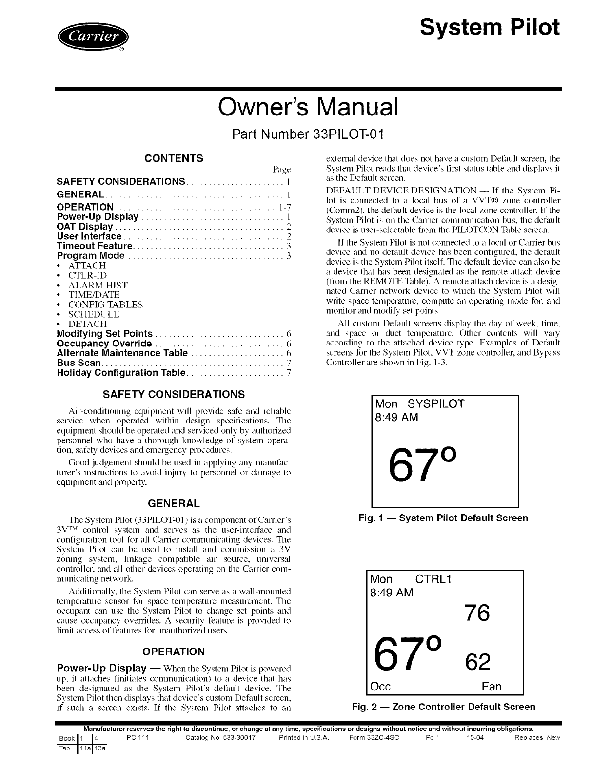
All custom Default screens display the day of week, time,
trod space or duct temperature. Other contents will valy
according to the attached device type. Examples of Default
screens for the System Pilot, VVT zone controller, and Bypass
Controller are shown in Fig. 1-3.
SAFETY CONSIDERATIONS
Air-conditioning equipment will provide safe and reliable
service when operated within design specifications. The
equipment should be operated and serviced only by authorized
personnel who have a thorough knowledge of system opera-
tion, safety devices and emergency procedures.
Good judgement should be used in applying any manufac-
turer's instructions to avoid injury to personnel or damage to
equipment and property.
GENERAL
The System Pilot (33PILOT-01 ) is a component of Camer's
3V TM control system and serves as the user-interface and
configuration tool for all Carrier communicating devices. The
System Pilot can be used to install and commission a 3V
zoning system, linkage compatible air source, univers_d
controller, and all other devices operating on the Carrier com-
municating network.
Additiomdly, the System Pilot can serve as a w_dl-mounted
temperature sensor for space temperature measurement. The
occupant can use the System Pilot to change set points and
cause occupancy ovemdes. A security feature is provided to
limit access of features for unauthorized users.
OPERATION
Power-Up Display -- When the System Pilot is powered
up, it attaches (initiates communication) to a device that has
been designated as the System Pilot's default device. The
System Pilot then displays that device's custom Default screen,
if such a screen exists. If the System Pilot attaches to an
Mon SYSPILOT
8:49 AM
67 °
Fig. 1 -- System Pilot Default Screen
Mon CTRL1
8:49 AM 76
7 62
Occ Fan
Fig. 2-- Zone Controller Default Screen
Manufacturer reserves the right to discontinue, or change at any time, specifications or designs without notice and without incurring obligations.
Book 1 ]4 PC 111 Catalog No. 533-30017 Printed in US.A. Form 33ZC-4SO Pg 1 10-04 Replaces: New
I
Tab 11a 13a
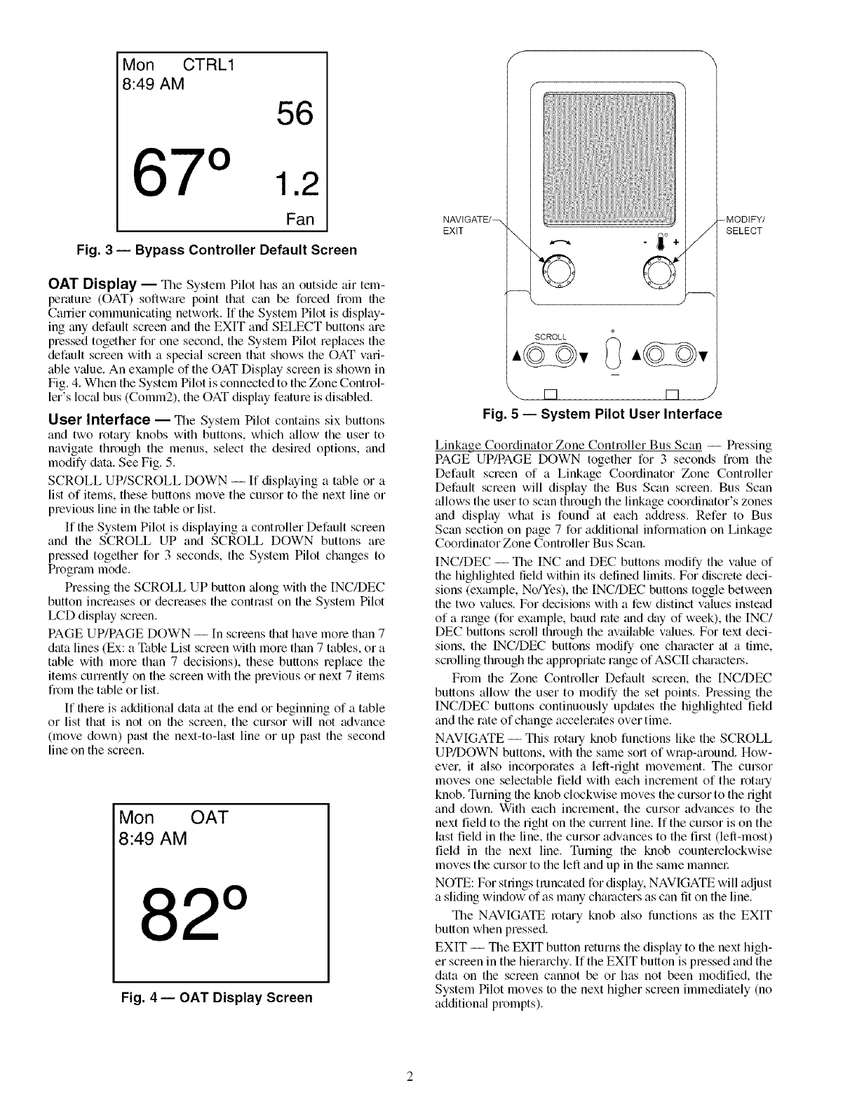
Mon CTRL1
8:49 AM
56
71.2
Fan
Fig. 3 -- Bypass Controller Default Screen
OAT Display -- The System Pilot has an outside air tem-
peratme (OAT) software point that can be forced from file
Carrier communicating netwoN. If the System Pilot is display-
ing any default screen and the EXIT and SELECT buttons are
pressed together for one second, the System Pilot replaces the
default screen with a special screen that shows the OAT vari-
able v_flue. An example of the OAT Display screen is shown in
Fig. 4. When the System Pilot is connected to the Zone Control-
let's lucid bus (Comm2), the OAT display feature is disabled.
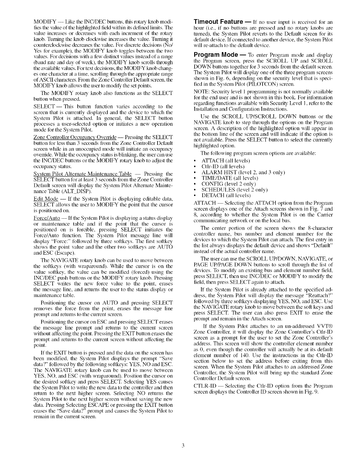
User Interface -- _nle System Pilot contains six buttons
and two rotary knobs with buttons, which allow the user to
navigate through the menus, select the desired options, and
modify data. See Fig. 5.
SCROLL UP/SCROLL DOWN -- If displaying a table or a
list of items, these buttons move the cursor to the next line or
previous line in the table or list.
If the System Pilot is displaying a controller Default screen
and the SCROLL UP and SCROLL DOWN buttons are
pressed together for 3 seconds, the System Pilot changes to
Prograln mode.
Pressing the SCROLL UP button _dong with the INC/DEC
button increases or decreases the contrast on the System Pilot
LCD display screen.
PAGE UP/PAGE DOWN --In screens that have more than 7
data lines (Ex: a Table List screen with more than 7 tables, or a
table with more than 7 decisions), these buttons replace the
items currently on the screen with the previous or next 7 items
from the table or list.
If there is additional data at the end or beginning of a table
or list that is not on file screen, the cursor will not advance
(move down) past the next-to-last line or up past the second
line on the screen.
Mon OAT
8:49 AM
82°
Fig. 4 -- OAT Display Screen
S
NAVtGATE/_
EXiT \
[] rq
Fig. 5 -- System Pilot User Interface
--MODIFY/
SELECT
Linkage Coordinator Zone Controller Bus Scan -- Pressing
PAGE UP/PAGE DOWN together for 3 seconds from the
Default screen of a Linkage Coordinator Zone Controller
Default screen will display the Bus Scan screen. Bus Scan
allows the user to scan through the linkage coordinator's zones
and display what is found at each addi'ess. Refer to Bus
Scan section on page 7 for additional information on Linkage
Coordinator Zone Controller Bus Scan.
INC/DEC -- The INC and DEC buttons modify the v_flue of
the highlighted field within its defined limits. For disclete deci-
sions (example, No/Yes), the INC/DEC buttons toggle between
the two values. For decisions with a few distinct values instead
of a range (for example, baud rote and &ty of week), the INC/
DEC buttons scroll through the available v_dues. For text deci-
sions, the INC/DEC buttons modify one chm'acter at a time,
scrolling through the appropriate range of ASCII chmactel_.
From the Zone Controller Default screen, the [NC/DEC
buttons allow the user to modify the set points. Pressing the
INC/DEC buttons continuously updates the highlighted field
and the rate of change accelerates over time.
NAVIGATE -- This rotary knob functions like the SCROLL
UP/DOWN buttons, with the same sort of wrap-around. How-
ever. it also incorporates a left-right movement. The cm_or
moves one selectable field with each increment of the rottuy
knob. Turning file knob clockwise moves the cursor to the right
and down. With each increment, the cursor advances to the
next field to the right on the current line. If the cm:sor is on the
last field in the line, the cursor advances to the first (left-most)
field in the next line. Turning the knob counterclockwise
moves the cursor to the left and up in file same mannel:
NOTE: For strings truncated for display. NAVIGATE will adjust
a sliding window of as many characters as can fit on the line.
The NAVIGATE rotmy knob also functions as the EXIT
button when pressed.
EXIT -- Tile EXIT button returns the display to file next high-
er screen in the hierarchy. If the EXIT button is pressed and the
data on the screen cannot be or has not been modified, the
System Pilot moves to file next higher screen immediately (no
additiomfl prompts).
MODIFY-- LikefileINC/DECbuttons,thisrotguTknobmodi-
liesfilevalueoffilehighlightedfieldwitNnitsdefinedlimits.The
v:-flueincreasesordecleaseswiflleachinclementoffilerotary
knob.Turningtheknobclockwiseincreasesthev:-flue.Turningit
counterclockwisedecreasesfilevalue.Fordiscretedecisions(No/
Yesforexample),fileMODIFYknobtogglesbetweenthetwo
values.Fordecisionswithafewdistinctv:-fluesinsteadofarange
(baudroteand&tyofweek),theMODIFYknobscrolls[hrough
the available values. For text decisions, the MODIFY knob chang-
es one character :_ita time, scrolling through the appropriate range
of ASCII chamctel.s. From the Zone Controller Default screen, the
MODIFY knob allows the user to modify the set points.
The MODIFY rota qknob also functions as the SELECT
button when pressed.
SELECT--This button function varies according to the
screen that is currently displayed and file device to which the
System Pilot is attached. In general, the SELECT button
processes a user-selected option or initiates a new operation
mode for the System Pilot.
Zone Controller Occupancy Override -- Pressing the SELECT
button for less than 3 seconds from the Zone Controller Default
screen while in an unoccupied mode will initiate an occupancy
override. While file occupancy status is blinking, the user can use
the INC/DEC buttons or the MODIFY rotmy knob to adjust the
occupancy status.
System Pilot Alternate Maintenance Table -- Pressing the
SELECT button for at least 3 seconds from the Zone Controller
Default screen will display the System Pilot Alternate Mainte-
nance Table (ALT_DISP).
Edit Mode -- If the System Pilot is displaying editable &tta,
SELECT allows the user to MODIFY the point that the cursor
is positioned on.
Force/Auto --If the System Pilot is displaying a status display
or maintenance table and if the point that the cm.sor is
positioned on is forcible, pressing SELECT initiates the
Force/Auto function. The System Pilot message line will
display "Force:" followed by three soilkeys. The first soilkey
shows the point value and the other two soilkeys are AUTO
and ESC (Escape).
The NAVIGATE rotary knob can be used to move between
the soilkeys (with wrapmound). While the cursor is on the
value soilkey, the v:-due can be modified (forced) using the
INC/DEC push buttons or the MODIFY rotary knob. Pressing
SELECT writes the new force value to the point, erases
the message line, and returns the user to file status display or
maintenance table.
Positioning the cursor on AUTO and pressing SELECT
removes file force from the point, erases the message line
prompt and returns to the current screen.
Positioning the cursor on ESC and pressing SELECT erases
the message line prompt and returns to the current screen
wifllout affecting the point. Pressing the EXIT button erases the
prompt and returns to the current screen without affecting the
point.
If the EXIT button is pressed and the &tta on the screen has
been modified, file System Pilot displays the prompt "Save
data?" followed by the following soilkeys: YES, NO and ESC.
The NAVIGATE rotary knob can be used to move between
YES, NO, and ESC (with wraparound). Position the cursor on
the desired softkey and press SELECT. Selecting YES causes
the System Pilot to write the new data to the controller and then
return to the next higher screen. Selecting NO returns the
System Pilot to the next higher screen without saving the new
data. Pressing Selecting ESCAPE or pressing the EXIT button
erases the "Save data'?" prompt and causes the System Pilot to
remain in the cunent screen.
Timeout Feature -- If no user input is ]eceived for an
hour (i.e., if no buttons are pressed and no rotary knobs are
turned), the System Pilot reverts to the Default screen for its
default device. If connected to another device, the System Pilot
will re-attach to the default device.
Program Mode -- To enter Program mode and display
the Program screen, press the SCROLL UP and SCROLL
DOWN buttons together for 3 seconds from the default screen.
The System Pilot will display one of the three program screens
shown in Fig. 6, depending on the security level that is speci-
fied in the System Pilot (HLOTCON) screen.
NOTE: Security level 1 programming is not normally available
for the end user and is not shown in this book. For information
regarding functions available with Security Level 1, refer to the
Installation and Configuration Instructions.
Use the SCROLL UP/SCROLL DOWN buttons or the
NAVIGATE knob to step through the options on the Program
screen. A description of the highlighted option will appear in
the bottom line of the screen and will indicate if the option is
not available. Press file SELECT button to select the currently
highlighted option.
The following program screen options are avaikible:
• ATTACH (all levels)
• Ctlr-ID (all levels)
• ALARM HIST (level 2, and 3 only)
• TIME/DATE (all levels)
• CONFIG (level 2 only)
• SCHEDULES (level 2 only)
• DETACH (all levels)
ATTACH -- Selecting the ATTACH option from the Program
screen displays one of the Attach screens shown in Fig. 7 and
8, according to whether the System Pilot is on the Carrier
communicating network or on the local bus.
The center portion of the screen shows the 8-character
controller name, bus number grad element number for the
devices to which the System Pilot can attach. The first entry in
file list always displays the default device and shows "Default"
instead of the actual controller name.
The user can use the SCROLL UP/DOWN, NAVIGATE, or
PAGE UP/PAGE DOWN buttons to scroll through the list of
devices. To modify an existing bus and element number field,
press SELECT. then use INC/DEC or MODIFY to modify the
field, then press SELECT again to attach.
If the System Pilot is already attached to the specified ad-
diess, the System Pilot will display the message "Reattach?"
followed by three softkeys dispktying YES, NO, and ESC. Use
file NAVIGATE rotary knob to move between the soil keys and
press SELECT. The user can also press EXIT to erase the
prompt and remain in the Attach screen.
If the System Pilot attaches to an un-addressed VVT®
Zone Controllek it will display the Zone Controller's Cth-ID
screen as a prompt for the user to set the Zone Controller's
address. This screen will show the controller element number
as 0, even though the controller will actu:-dly be at its default
element number of 140. Use the instructions in the CtI>ID
section below to set the address before exiting from this
screen. When the System Pilot attaches to an addressed Zone
Controllek the System Pilot will bring up the stan&lrd Zone
Controller Default screen.
CTLR-ID- Selecting the Ctlr-ID option from file Program
screen displays the Controller ID screen shown in Fig. 9.
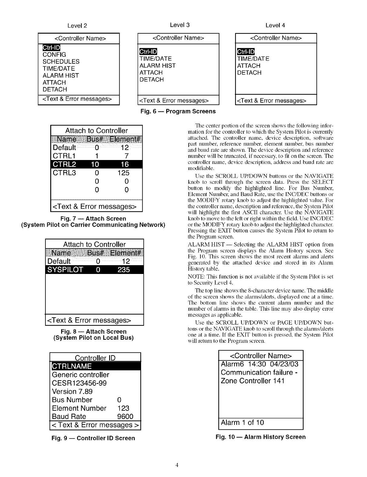
Level 2 Level 3 Level 4
<Controller Name>
CONFIG
SCHEDULES
TIM E/DAT E
ALARM HIST
ATTACH
DETACH
<Text & Error messages>
<Controller Name>
TIME/DATE
ALARM HIST
ATTACH
DETACH
<Text & Error messages>
Fig. 6 -- Program Screens
<Controller Name>
TIME/DATE
ATTAC H
DETACH
<Text & Error messages>
Attach to Controller
Default 0 12
CTRL1 1 7
CTRL3 0
0
0
125
0
0
<Text & Error messages>
Fig. 7 -- Attach Screen
(System Pilot on Carrier Communicating Network)
Attach to Controller
Default 0 12
<Text & Error messages>
Fig. 8 -- Attach Screen
(System Pilot on Local Bus)
Controller ID
The center portion of the screen shows the following infor-
mation for the controller to which the System Pilot is currently
attached. Tile controller name, device description, software
pall number, reference number, element number, bus number
and baud rate ale shown. The device description and reference
number will be truncated, if necessary, to fit on the screen. The
controller name, device description, address and baud rate are
modifiable.
Use the SCROLL UP/DOWN buttons or the NAVIGATE
knob to scroll through the screen data. Press the SELECT
button to modify the highlighted line. For Bus Number.
Element Numbek and Baud Rate, use the [NC/DEC buttons or
the MODIFY rotm-yknob to adjust the highlighted value. For
the controller nmne, description and reference, the System Pilot
will highlight the first ASCII charactel: Use the NAVIGATE
knob to move to the left or right within the field. Use INC/DEC
or the MODIFY rotaqknob to adjust the highlighted chamctel:
Pressing the EXIT button causes the System Pilot to return to
the Program screen.
ALARM HIST -- Selecting the ALARM HIST option from
the Program screen displays the Alarm History screen. See
Fig. 10. This screen shows the most recent alarms and alerts
generated by the attached device and stored in its Alarm
History table.
NOTE: This function is not available if the System Pilot is set
to Security Level 4.
The top line shows the 8-character device name. The middle
of the screen shows the alarms/alerts, displayed one at a time.
The bottom line shows the currant alarm number and the
number of ahums in the table. This line may also display enor
messages as applicable.
Use the SCROLL UP/DOWN or PAGE UP/DOWN but-
tons or the NAVIGATE knob to scroll through the alarms/alerts
one at a time. If the EXIT button is pressed, the System Pilot
will return to the Program screen.
Generic controller
CESR123456-99
Version 7.89
Bus Number 0
Element Number 123
Baud Rate 9600
< Text & Error messages >
Fig. 9 -- Controller ID Screen
<Controller Name>
Alarm6 14:30 04/23/03
Communication failure -
Zone Controller 141
Alarm 1 of 10
Fig. 10 -- Alarm History Screen
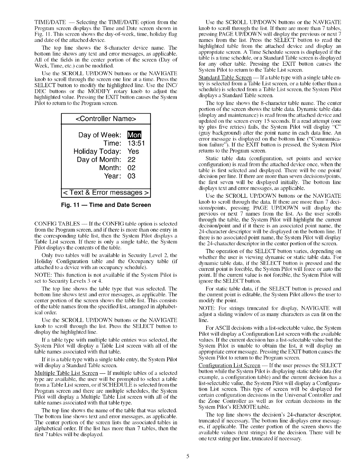
TIME/DATE -- Selecting the TIME/DATE option fiom the
Program screen displays the Time and Date screen shown in
Fig. 11. This screen shows the day-of-week, time, holiday flag
and date of the attached device.
The top line shows the 8-character device name. The
bottom line shows any text and error messages, as applicable.
All of the fields in the center portion of the screen (Day of
Week, Time, etc.) can be modified.
Use the SCROLL UP/DOWN buttons or the NAVIGATE
knob to scroll through the screen one line at a time. Press the
SELECT button to modify the highlighted line. Use the INC/
DEC buttons or the MODIFY rotary knob to adjust the
highlighted value. Pressing the EXIT button causes the System
Pilot to return to the Program screen.
<Controller Name>
Day of Week:
Time: 13:51
Holiday Today: Yes
Day of Month: 22
Month: 02
Year: 03
< Text & Error messages >
Fig. 11 -- Time and Date Screen
CONFIG TABLES -- If the CONFIG table option is selected
from the Program screen, and if there is mole than one entry in
the corresponding table list, then the System Pilot displays a
Table List screen. If there is only a single table, the System
Pilot displays the contents of the table.
Only two tables will be available in Security Level 2, the
Holiday Configuration table and the Occupancy table (if
attached to a device with an occupancy schedule).
NOTE: This function is not available if the System Pilot is
set to Security Levels 3 or 4.
The top line shows the table type that was selected. The
bottom line shows text and error messages, as applicable. The
center portion of the screen shows the table list. This consists
of the table nalnes from the specified list, arranged in alphabet-
ical ordel:
Use the SCROLL UP/DOWN buttons or the NAVIGATE
knob to scroll through the list. Press the SELECT button to
display the highlighted line.
If a table type with multiple table entries was selected, the
System Pilot will display a Table List screen with all of the
table names associated with that table.
If it is a table type with a single table ent U, the System Pilot
will display a Stan&_rd Table screen.
Multiple Table List Screen -- If multiple tables of a selected
type _ue available, the user will be prompted to select a table
from a Table List screen, or if SCHEDULE is selected from the
Program screen and there me multiple schedules, the System
Pilot will display a Multiple Table List scleen with all of the
table names associated with that table type.
The top line shows the name of the table that was selected.
The bottom line shows text and error messages, as applicable.
The center portion of the scleen lists the associated tables in
alphabetical ordel: If the list has more than 7 tables, then the
first 7 tables will be displayed.
Use the SCROLL UP/DOWN buttons or the NAVIGATE
knob to scroll through the list. If there are mole than 7 tables,
pressing PAGE UP/DOWN will display the previous or next 7
names from the list. Press the SELECT button to read the
highlighted table from the attached device and display an
appropriate scleen. A Time Schedule screen is displayed if the
table is a time schedule, or a Standm'd Table screen is displayed
for any other table. Pressing the EXIT button causes the
System Pilot to return to the Table List screen.
Standard Table Screen -- If a table type with a single table en-
try is selected from a Table List screen, or a table (other than a
schedule) is selected from a Table List screen, the System Pilot
displays a Stan&_rd Table screen.
The top line shows the 8-character table nmne. The center
portion of the screen shows the table data. Dynamic table data
(display and maintenance) is read from the attached device and
up&tted on the screen evely 15 seconds. If a read attempt (one
try plus five retries) fails, the System Pilot will display "C"
(gray background) after the point name in each data line. An
error message is displayed on the bottom line ("Communica-
tion failure"). If the EXIT button is pressed, the System Pilot
returns to the Program screen.
Static table &tta (configuration, set points and service
configuration) is read from the attached device once, when the
table is first selected and displayed. Thele will be one point/
decision per line. If thele are more than seven decisions/points,
the first seven will be displayed initially. The bottom line
displays text and error messages, as applicable.
Use the SCROLL UP/DOWN buttons or the NAVIGATE
knob to scroll through the data. If thele are more than 7 deci-
sions/points, pressing PAGE UP/DOWN will display the
previous or next 7 names from the list. As the user scrolls
through the table, the System Pilot will highlight the current
decision/point and if it there is an associated point name, the
24-character descriptor will be displayed on the bottom line. If
there is no associated point name, the System Pilot will display
the 24-character descriptor in the center portion of the screen.
The operation of the SELECT button varies, depending on
whether the user is viewing dynmnic or static table data. For
dynmnic table data, if the SELECT button is pressed and the
cunent point is forcible, the System Pilot will force or auto the
point. If the current value is not forcible, the System Pilot will
ignore the SELECT button.
For static table data, if the SELECT button is pressed and
the cunent point is editable, the System Pilot allows the user to
modify the point.
NOTE: For strings truncated for display. NAVIGATE will
adjust a sliding window of as many characters as can fit on the
line.
For ASCII decisions with a list-selectable v_flue, the System
Pilot will display a Configuration List screen with the available
values. If the current decision has a list-selectable value but the
System Pilot is unable to obtain the list, it will display an
appropriate error message. Pressing the EXIT button causes the
System Pilot to return to the Progrmn screen.
Configuration List Screen -- If the user presses the SELECT
button while the System Pilot is displaying static table data (for
example, a configuration table) and the current decision has a
list-selectable value, the System Pilot will display a Configura-
tion List screen. This type of screen will be displayed for
certain configuration decisions in the Universal Controller and
the Zone Controller as well as for certain decisions in the
System Pilot's REMOTE table.
The top line shows the decision's 24-character descriptor.
truncated if necessmy. The bottom line displays error messag-
es, if applicable. The center portion of the screen shows the
available values (text strings) for the decision. There will be
one text string per line, truncated if necessary.
UsetheSCROLLUP/DOWNbuttonsortheNAVIGATE
knobtoscrollthroughfilelist.If therearemorethan7 text
stringsinthelist,pressingPAGEUP/DOWNwilldispkiythe
previousornext7 textstingsfromthelist.If theSELECT
buttonispressed,fileSystemPilotwillreturntotheStandard
Tablescreenandwill showtheselectedtextstringasthe
currentdecisionvalue.TheSystemPilotwill displaythe
decisionvalueastext;howevel:it storesthevalueinthetable
accordingtothedecision'sdatatypeandlimits.Pressingthe
EXITbuttonwill causetheSystemPilotto returnto the
StandardTablescreenwithoutupdatingthecurrentdecision.
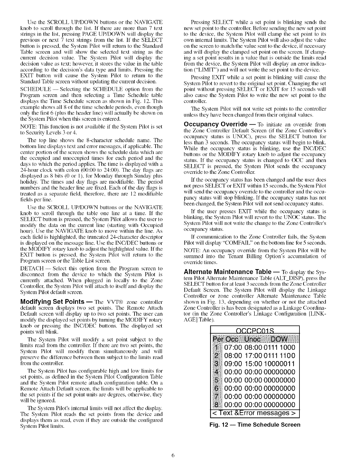
SCHEDULE-SelectingtheSCHEDULEoptionfiomthe
Programscreenandthenselectinga TimeScheduletable
displaystheTimeSchedulescreenasshowninFig.12.This
exampleshowsall8offiletimescheduleperiods,eventhough
onlythefirst6(plustheheaderline)willactuallybeshownon
theSystemPilotwhenthisscreenisentered.
NOTE:Thisfunctionisnotavailableif theSystemPilotisset
toSecurityLevels3or4.
Thetoplineshowsthe8-characterschedulename.The
bottomlinedisplaystextandenormessages,if applicable.The
centerportionofthescreenshowstheschedule&ttawhichare
theoccupiedandunoccupiedtimesforeachperiodandthe
daystowhichtheperiodapplies.Thetimeisdisplayedwitha
24-hourclockwithcolon(00:00to24:00).Thedayflagsm'e
displayedas8bits(0or1),forMondaythroughSundayplus
holiday.Thetimesanddayflagsaremodifiable.Theperiod
numbersandtheheaderlinem'efixed.Eachofthedayflagsis
treatedasaseparatefield,therefore,thereare12modifiable
fieldsperline.
UsetheSCROLLUP/DOWNbuttonsortheNAVIGATE
knobto scrollthroughfiletableonelineata time.If the
SELECTbuttonispressed,theSystemPilotallowstheuserto
modifythedataonthecurrentline(startingwithOccupied
hour).UsetheNAVIGATEknobtomovewithinfileline.As
eachfieldishighlighted,thetruncated24-chm'acterdescriptor
isdisplayedonthemessageline.UsetheINC/DECbuttonsor
theMODIFYrotaryknobtoadjustthehighlightedvalue.Ifthe
EXITbuttonispressed,theSystemPilotwill returnto the
ProgramscreenortheTableListscreen.
DETACH-SelectthisoptionfromtheProgramscreento
disconnectfromthedeviceto whichtheSystemPilotis
currentlyattached.Whenpluggedin locallyto fileZone
Controllel:theSystemPilotwillattachtoitselfanddisplaythe
SystemPilotdefaultscreen.
Modifying Set Points--The VVT® zone controller
default screen displays two set points. Tile Remote Attach
Default screen will display up to two set points. The user can
modify the displayed set points by turning file MODIFY rotary
knob or pressing the INC/DEC buttons. The dispkiyed set
points will blink.
The System Pilot will modify a set point subject to the
limits read from the controllel: If there are two set points, the
System Pilot will modify them simultaneously and will
preserve file difference between them subject to the limits read
from the controllec
The System Pilot has configurable high and low limits for
set points, as defined in the System Pilot Configuration Table
and the System Pilot remote attach configuration table. On a
Remote Attach Default screen, the limits will be applicable to
the set points if the set point units are degrees, otherwise, they
will be ignored.
The System Pilot's internal limits will not affect the display.
The System Pilot reads file set points from the device and
dispkiys them as read, even if they me outside the configured
System Pilot limits.
Pressing SELECT while a set point is blinking sends the
new set point to the controllel: Before sending the new set point
to the device, the System Pilot will clamp the set point to its
own internal limits. The System Pilot will also adjust the value
on file screen to match the value sent to the device, if necessmy
and will dispkiy the clmnped set point on the screen. If clamp-
ing a set point results in a value that is outside the limits read
from the device, the System Pilot will display an error indica-
tion ("LIMIT") and will not write the set point to the device.
Pressing EXIT while a set point is blinking will cause the
System Pilot to revert to the original set point. Changing the set
point without pressing SELECT or EXIT for 15 seconds will
also cause the System Pilot to write the new set point to the
controllel:
The System Pilot will not write set points to the controller
unless they have been changed from their original values.
Occupancy Override- To initiate an override from
the Zone Controller Default Screen (if the Zone Controller's
occupancy status is UNOC), press the SELECT button for
less than 3 seconds. The occupancy status will begin to blink.
While file occupancy status is blinking, use file INC/DEC
buttons or the MODIFY rotary knob to adjust the occupancy
status. If file occupancy status is changed to OCC and then
SELECT is pressed, the System Pilot sends file occupancy
override to the Zone Controllec
If the occupancy status has been changed and the user does
not press SELECT or EXIT within 15 seconds, the System Pilot
will send file occupancy ovenide to the controller and the occu-
pancy status will stop blinking. If the occupancy status has not
been changed, file System Pilot will not send occupancy status.
If the user presses EXIT while the occupancy status is
blinking, the System Pilot will revert to the UNOC status. The
System Pilot will not write the change to the Zone Controller's
occupancy status.
If communication to the Zone Controller fails, the System
Pilot will display "COMFAIU' on tile bottom line for 5 seconds.
NOTE: An occupancy override from the System Pilot will be
summed into the Tenant Billing Option's accumukition of
override times.
Alternate Maintenance Table -- To display the Sys-
teln Pilot Alternate Maintenance Table (ALT_DISP), press the
SELECT button for at least 3 seconds from the Zone Controller
Default Screen. The System Pilot will display the Linkage
Controller or zone controller Alternate Maintenance Table
shown in Fig. 13, depending on whether or not the attached
Zone Controller is has been designated as a Linkage Coordina-
tor (in the Zone Controller's Linkage Configuration [LINK-
AGEI Table
OCCPCOIR
< Text &Error messages >
Fig. 12 -- Time Schedule Screen
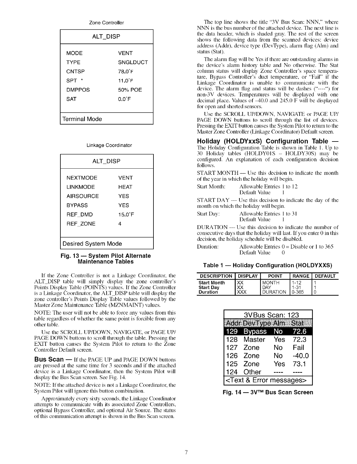
Zone Controller
ALT_DISP
MODE VENT
TYPE SNGLDUCT
CNTSP 78.0°F
SPT * 11.0°F
DMPPOS 50% POE
SAT 0.0°F
Terminal Mode
Linkage Coordinator
ALT DISP
NEXTMODE VENT
LINKMODE HEAT
AIRSOURCE YES
BYPASS YES
REFDMD 15.0_F
REF ZONE 4
Desired System Mode
Fig. 13- System Pilot Alternate
Maintenance Tables
If the Zone Controller is not a Linkage Coordinator. the
ALT_DISP table will simply display the zone controller's
Points Display Table (POINTS) values. If the Zone Controller
is a Linkage Coordinator, the ALT_DISP table will display the
zone controller's Points Display Table values followed by the
Master Zone Maintenance Table (MZNMAINT) values.
NOTE: The user will not be able to force _my values from this
table regardless of whether the same point is forcible from any
other table.
Use file SCROLL UP/DOWN, NAVIGATE, or PAGE UP/
PAGE DOWN buttons to scroll through file table. Pressing the
EXIT button causes the System Pilot to return to the Zone
Controller Default screen.
Bus Scan -- If the PAGE UP and PAGE DOWN buttons
are pressed at the same time for 3 seconds and if the attached
device is a Linkage Coordinator, then the System Pilot will
display the Bus Scan screen. See Fig. 14.
NOTE: If the attached device is not a Linkage Coordinator. the
System Pilot will ignore this button combination.
Approximately every sixty seconds, the Linkage Coordinator
attempts to communicate wifll its associated Zone Controllel.s,
option_fl Bypass Controller. and optional Air Source. The status
of this communication attempt is shown in the Bus Scan screen.
The top line shows the title "3V Bus Scan: NNN," where
NNN is the bus number of the attached device. The next line is
file &tta header, which is shaded gray. The rest of the screen
shows the following data from the scanned devices: device
address (Addr), device type (DevType), almm flag (Aim) and
status (Stat).
The alarm flag will be Yes if there me outstanding aimms in
the device's almm history table and No otherwise. The Stat
column status will display Zone Controller's space tempera-
ture, Bypass Controller's duct temperature, or "Fail" if the
Linkage Coordinator is unable to communicate with the
device. The _flarm flag and status will be dashes ("----") for
non-3V devices. Temperatures will be displayed with one
decimal place. Values of _40.0 and 245.0 F will be displayed
for open and sholled sensors.
Use the SCROLL UP/DOWN, NAVIGATE or PAGE UP/
PAGE DOWN buttons to scroll through the list of devices.
Pressing the EXIT button causes the System Pilot to return to the
Master Zone Controller (Linkage Coordinator) Default screen.
Holiday (HOLDYxxS) Configuration Table --
The Holiday Configuration Table is shown in Table I. Up to
30 Holiday rabies (HOLDY01S - HOLDY30S) may be
configured. An exphmation of each configuration decision
follows.
START MONTH -- Use this decision to indicate the month
of the year in which the holiday will begin.
Start Month: Allowable Entries 1 to 12
Default Value 1
START DAY -- Use this decision to indicate the day of the
month on which the holiday will begin.
Start Day: Allowable Entries 1 to 31
Default Value 1
DURATION -- Use this decision to indicate the number of
consecutive &tys that the holiday will last. If you enter 0 in this
decision, the holiday schedule will be disabled.
Duration: Allowable Entries 0 = Disable or 1 to 365
Default Value 0
Table 1 -- Holiday Configuration (HOLDYXXS)
DESCRIPTION DISPLAY POINT RANGE DEFAULT
Start Month XX MONTH 1-12 1
Start Day XX DAY 1-31 1
Duration XXX DURATION 0-365 O
3VBus Scan: 123
128 Master Yes 72.3
127 Zone No Fail
126 Zone No -40.0
125 Zone Yes 73.1
124 Other
<Text & Error messages>
Fig. 14 -- 3V TM Bus Scan Screen

Copyright 2004 Carrier Corporation
Manufacturer reserves the right to discontinue, or change at any time, specifications or designs without notice and without incurring obligations.
Book 11la 143a PC 111 Catalog No 533-30017 Printed in U.SA Form 33ZC-4SO Pg 8 10-04 Replaces: New
Tab
