CARRIER Humidifier Manual L0411155
User Manual: CARRIER CARRIER Humidifier Manual CARRIER Humidifier Owner's Manual, CARRIER Humidifier installation guides
Open the PDF directly: View PDF ![]() .
.
Page Count: 2
INSTALLATION INSTRUCTIONS FOR
SMALL AND LARGE BYPASS HUMIDIFIERS
READ COMPLETE SAFETY INSTRUCTIONS AND INSTALLATION iNFORMATION BEFORE STARTING.
product must be instal{ed by a qua}ified heating and air conditioning contractor Failure to do so could result in serious
injury from eieetrica_ shock This product must be installed in compliance with all _oca_,state, and federal codes,
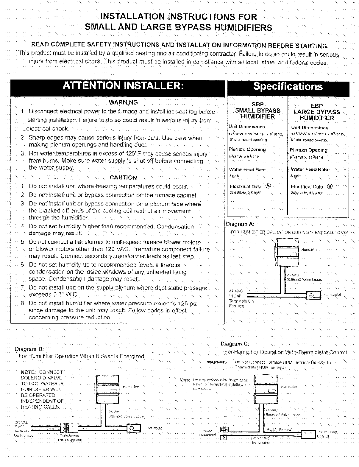
WARNING SBP
Drsconnect electncal aower to the furnace and _nstal_ lock-out tag before SMALL BYPASS
HUMIDIFIER
Si_r4rtg rlsfaJlat/o[] Fa]lut-e to do So goula r@su[[ [fl Serious _iqjuf _ from
_ectrl©_l SrlocK Urt]t Dtme/_ions
2 Sharp edges Iq_'_ cause serlou_ injur_ froR3 cutg US_ Care whet s- _,_ _,,.,,Jo_,._._
_flaKJtlg pt_f3um Ope[ltf)_s afx1 R_flt3f_rlg duct Plenum Opening
"10_ W_t@r _mDera_utes IR excess o_ 12_F ma_ Cause serious/tltUry _se_w t91,2-H
from Durnfl Make sure water suppFy _s shut off before c _nnectmg
tfl_ W_ter SUDDW _¢ater Feed Rat_
CAUTION __l,_
_O rlot Iftst_]l und WhiTe ffee, z/_g f_;TlpeTB_ures CQU]_ OCCUR Electr_al Da_
2 _O not {llsta][ U[1}t or bypass Collr_ectto_ OR the [umac_ Ca_]rfeL z4vs_ DSA_
_O no[ []3s_l tJI3_[ QF Dyp_ss CtOI3I_ec_IOR oR _ _lel_um T_Ce WD_f_
the blaIl_ed Of_ _r)f.tS Of tll_ COO_lr _ COH rest[ 3[ _]r Rqov_ftl_nl
4 L)o not Set num_lty nigher T_an recommended Conuensauon
o_m_ge may Fe_LI_I
5 Do not connect a transformer to multi4-)eed fuinace blower motors
3r D_ower f£otors other than 120 VAC Premature comuonent fa ure
may result Cort£ect secondar_ transformer leads as last Sled
6DO ROt Set [1ur131olt t_D to recomme;_ded leveIs _f there is
condensabon on the inside w}ndows of art. unr_ea[eo i]v_nq
_DaCe Condensation damage ma_ result
Z [)O r3o[ _I]S[_l_ Uf}ll OR IRe supply p_nurrl wf_ero Duct static pressure
exceeds 0 3" WC
8 3o not instal[ hum J;fie; wnere wale_ txessure exceeas 125 os}
_mce aamage to _ne unit r_a_ _osu_t FOllOW codes in effect
2ORC_FnI_ _ressUfe [_OLJC[[On
LBP
LARGE BYPASS
HUMIDIFIER
U_t Dime_sbn_
Pleltum Oper_l_lg
Wa_er Feed Rate
Electrical Data
_4v._ot4z _ 5 AM_
Diagram A:
_Of4 HUM}D_F[E£_ O p L]_.T[O N D JR[NO ")(}=At JALL' CINtY
UM ¸ ,, ,m- _ _,
_rq_ nyq O
Diagram B:
_or HIJITTrd}f_Pr floe_abon £_!he
NOTE CONNLC
SOLLNO]L) _4ttLV L
) He] _%'ATLR !F
HUMiD;F_FR V'V
_E OPERATED
NDLPLNDEN l _
_E;_TfNG CA[ _ S
R_f_ ¸ r. _4, H._
Diagram C.
Fol H_m]d tier (" _erabon Wltll [ h_rm_d _[at Centre/
_4_f{N]NG DU Nt_t C,_n_r=rH a_ HUM T_-q-_na D __-:_ T_
.rF _ a. HeN pr¢_r_
.u ,.r
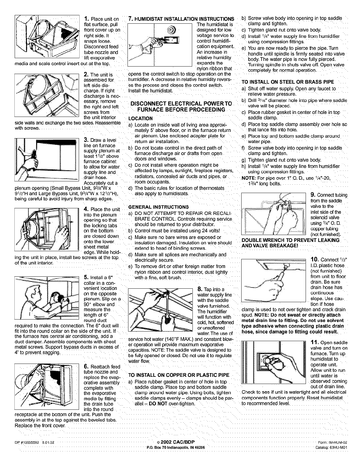
"_ t. Place unit on
fro13t cover UD 0_
r_gnt sioe_ it
sn_ps teose_
Disconnect feed
t_tDe nOZZle anc
i_ eva Dor_t_ve
media and scale control insert out at the top.
2. The unit is
assembled fo_
left side dis-
charge• if right
olscna_e is rle_
essary, _n love
lne r_ghl and left
screws from
the unit in_n_
sKle wal_ ano ox_ lan_ the _ _12_s. Reassemble
w_ Screv,_.
3. Draw a leve{
ne o13 furnace
SUpply plenum at
least 11/2_ above
furnace cabinet
to aIIow for water
suppt_ ne ano
oraln Rose
Accurately CUt a
plenum opening (Small Bypass un_ 9: 8_W x
9V2'H and Large Bypass Unit 93/4"W :_ 121/2_H
being careful to avoid injury from sEarp eoges.
4. Ptace the unit
r3fD ire Plenum
opening so g3a[
i]3e lOCKing Ia_3s
On [Re Dotv_nq
a_ CIoseo _'Jown
onto the tower
sheet metal
e_ge. While hold-
ing the _ng iR pl_ce, ns[all [we screws at [rle lop
of the unit interio_
i _ • Coll_r _Ra CUR-
ve nleni IOCa_On
On [Re ODDOSI_
Plenum. Siio on a
90 _ elbow and
me_sure ire
_ength of 6"
roun£J OUC_
required to make the conneet_n The 6" duet wil
fit into the round collar on the side of the unit. If
the furnace has central air condit_ning, ad_ a
duct dampe_ Assemble cot Rconen_s With sReel
metal screws. Support bypass ducts in excess of
4" to prevent sagging
6. Reattachfeec
tube noz.zIe and
re£ ace ire evap-
orative assem[ •
comoleie w_[n
[Re ev_ DOT_tlve
media by fitting
the drain tube
r3[o ire rOHRO
receptacle at the bottom of the unit. Push the
assembly in _ ire to_ _atns[ ire Develeo taps.
Re_ ace the front cove_
7. HUMIDISTAT INSTALLATION INSTRUCTIONS
The humidistat is
_esEgned _ low
voltage se_vl_ 113
_ntrol n{ _idifi-
3_lon eo ull_3'lenl.
An _nc_ase Ill
_el_lVe numlolIy
ex_aPA_ slhe
n_on r_bbon that
opens IRe _ntrol SWIICn io SIOO ooersiion On ire
_um_di_e_ A decrease in relative humidity revers-
es ine Drl_SS 8130 Closes ire ex)nirot _I[CF
nstall the humi_istat.
DISCONNECT ELECTRICAL POWER TO
FURNACE BEFORE PROCEEDING
LOCATIOh
al Locate oq inside wall of I_ving area aporox_-
mate r 5' above floor or in the furnac_ returr
air plenum Use enclosed adapter Plate for
return air ins_31tatlor
3 Do not locate control in the c rec_oathof
fHrnace discharge air or _ra_ts frop-t o_eri
leers _n(] wlnoows.
cDo not install where o_eraiion re{grit De
affected bv =amos. sur ight, fireplace registers
rBGl_[ors, concealeo a_r Gucts _n_ D{oes or
rcon_ occuoan_s.
DI Screw valve body into opening in top saddle
clamD nag _ghten.
C) Tighten gtend nut onto valve bod_
0 Install /4" wa_er supply tine from humidlt_er
using compression fl_ngs
eYou are now ready to pierce the pipe. Turn
handle unto{ spindle is firmly seated into valve
body_ The water pipe is now fully pieced.
T=_rning spindle in shu_s valve off. Open valve
completely for normal operation¸
TO INSTALL ON STEEL OR BRASS PIPE
a Sh_toffwatersuppl_Openanyfaueotto
r elleve wa[er p_essLt_.
D_ Drill 3//6" diameter hole into pipe where sa_dte
valve will be placed.
c Ptace rubber gasket in center of hote in top
s_dle ci_mp.
d Ptaee top saddle clamp assembly ove_ hole so
_hat lance fits inb3 hole¸
ePtace too and bottom saddle clamp around
water p_pe
Screw valve body inlo opening in top saddle
clamp and tighten.
g) Tighten gtend nut onto valve bng_
_s_a_ /4 ¸wa[er supply tine from humiditier
using compression _ngs.
NOTE: For pipe over 1° O. D., use//4"-20,
-3/#, long bc_ts.
_] The basic rules for location of -hermostats
a_so _ppty to n umlolsl _ts.
GENERAL INSTRUCTIONS
aDO NOT ATTEMPT TO REPAIR OR RECALl-
BRATE CONTROL. Controls rem_mng serwce
s_30u_(3be re_u_ne(_ E]our ¢JISlrIDU[O_
3 Control must be installed using 24 volts!
3Make sure no bare w]_s are e×ooseG or
9, Connect _b}ng
frcm the saddle
vane te the
inlet side of the
soler_d va;ve
using _/4"O. El
copper tubing
(not thrnished).
_sulat_oR o_mageo. _nsu_aiion on wife snoul_
extend to head of binding screws.
oMake s_re all sol=ces are mechan_cally ano
e_ectrlcz , secure.
eTo re_l'_ove dirt or other foreign m_|ter from
nylon rtDDOn anO COREO} in[enor, oust tg_3tJy
_ith a ftee soft brusl
8. _o n_o 8
water SU_ line
wlin ire sa_le
valve furnishe_
The humidifier
will function wit_
COl_ nOl s_el_d
cr unsoftened
water The use o_
serwce hot water 1140_F MAX ano constsn[ O_OW-
e_ o_[io_ wl}l orovl(]e maximum evaDo_ailve
capa_fles. NOTE: The saddle valve is des_neo Io
3e f_ y opened or dosed. Do not use it to regu_ale
w_e£ l_ow
_-O INSTALL ON COPPER OR PLASTIC PIPE
a Place rubber gasket in center of hole in too
saddle c_am_ Place to_ _Ra DOI_om sao(31e
_lamD arouno water biDe. Uslng D01_S, tighten
_add]e c_am_s evenly - Ci_mps SROUIG De D_r-
allel - DO NOT over-tign_en.
DOUBLE WRENCH TO PREVENT LEAKING
AND VALVE BREAKAGE!
10. Connec{ 112"
LD. plastic hose
(not furnished)
from unit to floor
drain• Be s=_re
drain hose has
continuOUS
siope. Use cau-
tion if hose
clamo _s useG _ no_ over _ghten and crack d_ain
scud. NOTE: Do not sweat or directly attach
metal drain line to fitting, DO not use solvent
type adhesive when connecting plastic drain
hose. since damage to fitting could result.
i __ 11. Open saddte
valve and turn on
furnace. Turn up
humidtetat to
operate unit.
AJlow unit to run
until water is
observed coming
out of drain tine.
CheCk to see if unit is watertight and all electrical
comconent_ func_ior pmperl_ Reset humidislat
to _commenoeo {eve_.
DP _0005592 5 01 02 © 2002 CAC/BDP Form M-HUM-02
F_(& BOX 70 I_iar=a_l_S N462_ Cala_o_ _3HU-M0_
