CARRIER Package Units(both Units Combined) Manual L0501602
User Manual: CARRIER CARRIER Package Units(both units combined) Manual CARRIER Package Units(both units combined) Owner's Manual, CARRIER Package Units(both units combined) installation guides
Open the PDF directly: View PDF ![]() .
.
Page Count: 52

AQUASNAP ®
30RB060-390
Air-Cooled Chillers
60 Hz
Installation Instructions
CONTENTS
Page
SAFETY CONSIDERATIONS ...................... 1
INTRODUCTION ............................... 1-23
INSTALLATION ............................... 24-52
Storage ......................................... 24
Step 1 -- Rig and Place the Unit ................. 24
• PLACING UNIT
• MOUNTING UNIT
• RIGGING UNIT
Step 2 -- Remove Compressor Rack Holddown
Bolts ............................................ 24
Step 3 -- Cooler Fluid and Drain Piping
Connections .................................. 27
• FREEZE PROTECTION
• UNITS WITH HYDRONIC PUMP PACKAGE
• UNITS WITHOUT HYDRONIC PUMP PACKAGE
• FOR ALLUNITS
Step 4-- Fill the Chilled Water Loop ............ 31
• WATER SYSTEM CLEANING
• WATER TREATMENT
• SYSTEM PRESSURIZATION
• FILLING THE SYSTEM
• SET WATER FLOW RATE
• PUMP MODIFICATION/TRIMMING
• PREPARATION FOR YEAR-ROUND
OPERATION
• FREEZE PROTECTION
• PREPARATION FOR WINTER SHUTDOWN
Step 5 -- Make Electrical Connections .......... 41
• POWER SUPPLY
• POWER WIRING
•CONTROL POWER
• FIELD CONTROL OPTION WIRING
• DUAL CHILLER LEAVING WATER SENSOR
• CARRIER COMFORT NETWORK COMMUNICA-
TION BUS WIRING
• NON-CCN COMMUNICATION WIRING
Step 6 -- Install Accessories .................... 52
• NAVIGATOR TM DISPLAY
• REMOTE ENHANCED DISPLAY
• LOW AMBIENT OPERATION
• MINIMUM LOAD ACCESSORY
• UNITSECURITY/PROTECTION ACCESSORIES
• COMMUNICATION ACCESSORIES
• SERVICE OPTIONS
Step 7-- Refrigerant Circuit ..................... 52
• LEAK TESTING
• DEHYDRATION
• REFRIGERANT CHARGE
SAFETY CONSIDERATIONS
Installing, starting up, and servicing air-conditioning
equipment can be hazardous due to system pressures, electrical
components, and equipment location.
Only trained, qualified installel.s and service mechanics
should install, stCut up, and service this equipment.
Untrained personnel can perform basic maintenance func-
tions such as cleaning coils. All other operations should be
performed by trained service personnel.
When working on the equipment, observe precautions in the
literature and on tags, stickers, and labels attached to the
equipment.
• Follow all safety codes.
• Keep quenching cloth and fire extinguisher nearby when
brazing.
• Wear safety glasses and work gloves.
• Use care in handling, rigging, and setting bulky
equipment.
ELECTRIC SHOCK HAZARD
Open all remote disconnects before servicing
this equipment.
IMPORTANT: This equipment generates, uses, and can
radiate radio frequency energy and if not installed and
used in accordance with these instructions may cause
radio interference. It has been tested and found to comply
with the limits of a Class A computing device as defined
by FCC (Federtfl Communications Commission, U.S.A.)
regulations, Subpart J of P_ut 15, which are designed to
provide reasonable protection against such interference
when operated in a commerci_fl environment.
This system uses R-410A, which has higher pressures than
R-22 and other refrigerants. No other refrigerant may be
used in this system. Gage set, hoses, and recovery systems
must be designed to handle R-410A refrigerant. If unsure
about equipment, consult the equipment manufacturel:
INTRODUCTION
These instructions cover installation of 30RB060-390 air-
cooled liquid chillers with electronic controls and units with
factoq-installed options (FIOPs). See Fig. 1.
Manufacturer reserves the right to discontinue, or change at any time, specifications or designs without notice and without incurring obligations.
PC 903 Catalog No, 533-00061 Printed in U.S,A, Form 30RB-1SI Pg 1 12-04 Replaces: New

30RB - Air-Cooled AquaSnap Chiller
Design Series
Nominal Sizes*
060 110 170 275
070 120 190 300
080 130 2t0 315
090 150 225 330
100 160 250 345
360
390
Voltage
1 = 575-3-60
2 = 380-3-60
5 = 208/230-3-60
6 = 460-3-60
3ORB
TA 21oo
Condenser Coil and Sound Options
--Aluminum Fin/Copper Tube (Standard)
0 - Copper Fin/Copper Tube
1 - Aluminum Precoat Fin/Copper Tube
2 - Aluminum E-coat Fin/Copper Tube
3 - Copper E-coat Fin/Copper Tube
6 - Aluminum Fin/Copper Tube, Low Sound Enclosure
7 - Copper Fin/Copper Tube ,Low Sound Enclosure
8 - Aluminum Pre-coated Fin/Copper Tube, Low Sound Enclosur_
9 - Aluminum E-coat Fin/Copper Tube, Low Sound Enclosure
B- Copper E-coat Fin/Copper Tube, Low Sound Enclosure
LEGEND
EMM -- Energy Management Module
GFI-CO -- Ground Fault Interrupting Convenience Outlet
LON -- Local Operating Network
*Refer to Table 1 on page 3 for modular unit combinations.
Quality Assurance
Certified to ISO 9001:2000
SecuritylPackaging Option
L- Coil Face Shipping Protection
0 - Skid
1 - Skid, Top Crate and Bag
3 - Coil Face Shipping Protection, Condenser Coil Trim Panels
4 - Skid, Condenser Coil Trim Panels
5 - Skid, Top Crate and Bag, Condenser Coil Trim Panels
7 - Coil Face Shipping Protection, Condenser Coil Trim Panels, Upper
and Lower Grilles
8 - Skid, Condenser Coil Trim Panels, Upper and Lower Grilles
9 - Skid, Top Crate and Bag, Condenser Coil Trim Panels, Upper
and Lower Grilles
C- Coil Face Shipping Protection, Condenser Coil Trim Panels, Upper and
Lower Grilles, Hail Guards
D- Skid, Condenser Coil Trim Panels, Upper Grilles and Lower Grilles,
Hail Guards
F- Skid, Top Crate and Bag, Condenser Coil Trim Panels, Upper and
Lower Grilles, Hail Guards
Cont rols/Communication Option
- - None
0 - EMM
t-Remote Service Port, GFI-CO
2 - EMM, Remote Service Port, GFI-CO
7 - BACnet Translator
8 - BACnet Translator, EMM
9 - BACnet Translator, Remote Service Port, GFI-CO
B- BACnet Translator, EMM, Remote Service Port, GFI-CO
H - LON Translator
J - LON Translator, EMM
K- LON Translator, Remote Service Port, GFI-CO
L - LON Translator, EMM, Remote Service Port, GFI-CO
Electrical Option
- - Single Power Connection, No Terminal Block
3 - Dual Power Connection, NoTerminal Block
7 - Single Power Connection, Non-Fused Disconnect
C - Dual Power Connection, Non-Fused Disconnect
Refrigeration Circuit Option
-- No Suction Line Insulation
0 - Suction Insulation
1 - Suction Service Valves
2- Head Pressure Control Operation
3 - Suction Insulation, Suction Service Valves
4 - Suction Insulation, Head Pressure Control Operation
5 - Suction Service Valves, Head Pressure Control Operation
6 - Suction Insulation, Service Valves, Head Pressure Control Operation
7- Minimum Load Control
8 - Suction Insulation, Minimum Load Operation
9 - Suction Service Valves, Minimum Load Control
B- Head Pressure Control Operation, Minimum Load Control
C - Suction Insulation, Suction Service Valves, Minimum Load Control
D- Suction Insulation, Head Pressure Control Operation, Minimum Load Control
F - Suction Service Valves, Head Pressure Control Operation, Minimum Load Control
G - Suction Insulation, Suction Service Valves, Head Pressure Control Operation,
Minimum Load Control
Cooler Option
- - Integral Cooler
0 - Integral Cooler, Cooler Heater
1 - Remote Cooler
9 - Integral Cooler, Brine
B- Integral Cooler, Cooler Heater, Brine
C - Remote Cooler, Brine
M- Integral Cooler, Non-Removable Core Filter Drier
N - Integral Cooler, Cooler Heater, Non-Removable Core Filter Drier
P- Remote Cooler, Non-Removable Core Filter Drier
Hydronics Option
-- No Pump Installed
0- Single Pump, 3 HP
1 - Single Pump, 5 HP
2 - Single Pump, 7.5 HP
3 - Single Pump, 10 HP
4 - Single Pump, 15 HP
6 - Dual Pump, 3 HP
7 - Dual Pump, 5 HP
8 - Dual Pump, 7.5 HP, Low Head
9 - Dual Pump, 7.5 HP, High Head
B- Dual Pump, 10 HP
C - Dual Pump,15 HP
Fig. 1 -- AquaSnap® Chiller Model Number Designation

NOTE: Unit sizes 315-390 are moduku units that me shipped
in sep_u'ate sections as modules A or B as noted in position 8 of
the unit model nomenclature. Installation dilections specific to
these units are noted in these instructions. For modules 315A,
315B, 330A, 330B, 345A, 345B, and 360B, follow all general
instructions as noted for unit sizes 30RB 160-170. For modules,
360A, 390A, and 390B follow instructions for 30RBI90. See
Table 1 for a listing of unit sizes and moduku" combinations.
NOTE: The nameplate for modular units contains only the first
two digits in the model numbel: For example, 315A and 315B
name plates read 31A and 3lB.
Table 1 -- Modular Combinations
MODULE UNITS MODULE A MODULE B
30RBA315 30RBA160 30RBA160
30RBA330 30RBA170 30RBA160
30RBA345 30RBA170 30RBA170
30RBA360 30RBA190 30RBA170
30RBA390 30RBA190 30RBA190
NOTE: An "A" in the model number indicates the design series.
Inspect the unit upon mriv_fl for damage. If damage is
found, file a claim right away with the shipping company.
When considering location for the unit, be sure to consult
National Electrical Code (NEC, U.S.A.) and local code
requirements. Allow sufficient space for airflow, wiring,
piping, and service. See Fig. 2-13. Be sure surface beneath the
unit is level, and is capable of supporiing the operating weight
of the unit. See Fig. 14 and Tables 2A-3B for unit mounting
and operating weights.
NOTE: To facilitate refrigerant vent piping all units have
fusible plugs with 1/4 in. SAE (Society of Automotive
Engineel_) times if required by local codes.

4_
NOTES:
1.
2.
3.
4.
Unit must have clearances as follows:
Top -- Do not restrict.
Sides and End -- 6" from solid surface.
All pumps have drains located at the bottom of volute
for draining.
Temperature relief devices are located on suction line,
liquid line and filter drier of each circuit and have 1/4"
flare connection.
Units without a pump package have the same leaving
water connection, Y and Z dimensions (entering
water) and Pump Discharge X dimensions as units
with a pump package.
5. Dimensions are in mm [inches].
'SERVICZ AREA 121921480] FROW EACH SIRE OF THE UNIT
-- 14478[51RI
COOLER rU8E
i G[RVICE AREA
F
POE
L
28102
[1106]
PUMP PACKAGE
WATER
4' VIOTAULIC 86093
(SEE NOTE _) 133895]
37G01
[14RO]
DETAIL A
RIGGING HOLE
RIGGING HOLE
114R6]
4500
I17r]
OETAIL A
SCALE 1:2
AIR rLOW
i" - ..... b
: ; L:
2463
(9701
215518
184 8ST
ONTROLIPOWER
_ALL VOLTAGES BOX
7!8 _KNOCKOUT TO 8[
FUSED FOR LOCATING
FIELO POWER WIRING
t90 R0
[r4Gt
-33650
[13,25]
4045
[_59}
45G63
11798)
WEIGHT MAX WEIGHT WEIGHT MAX WEIGHT CENTER OF GRAV]rY PUMP SUCTION (PS) PU_P GIGCHARGE (PD)
OUIAL CU/AL PUWP CUICU CU/C_/_ME CGx CG
,6,,R '_"9 '_", -- ,...,0,, .. ,,_u_l±!25±!95JRs±!2s_!2s±!R5
3ORB-eGo 3872 4705 4354 5187 llG4 1038 6756 309.9 3531 3RLR 3759 447.0
1756 2134 }e7E 2353 [_582] [408G) [266] I12Rl [139] [IS.O] [I_83 [IrR]
4077 4911 4560 5393 1165 1013 GERG 3099 3531 38t0 3759 4470
3ORB,OTO 1849 2558 5068 2446 [_R861 13RG81 [2661 [122} II3,R] [ISOi [1483 [ITG]
45669
[17.98]
Fig. 2 -- 30RB060, 070 Air-Cooled Chiller Dimensions

L_
NOTES:
1.
2.
3,
4.
Unit must have clearances as follows:
Top -- Do not restrict.
Sides and End -- 6' from solid surface.
All pumps have drains located at the bot-
tom of volute for draining.
Temperature relief devices are located on
suction line, liquid line and filter drier of
each circuit and have 1/4"flare connection.
Units without a pump package have the
same leaving water connection, Y and Z
dimensions (entering water) and Pump
Discharge X dimensions as units with a
pump package.
Dimensions are in mm [inches].
14478 157D1
SERVICE AREA 121RD[4803 FROM EACH SIDE or THE UNIT
m
q
296.46
111.673
TT
1'"iDA'
R'
{66.6AI 110 90]
PiPiNG ENTRANCE AREA
114 _ NTP
PUMP
2281.37 LEAVIRG WATER
IGR,GD] 4" VICTAULIC
COOLER DRAIN
314" NPT
PDr
NO PUMP PACRAGE
_ENTERING WATER
4" VICTAULIC
(SEE ROTE 4)
/sSEE DETAIL A
38D 88
115231
5_8.92
[R0433
45663
[17.98]
ERTERING WATER
A" VICTAULIC _
982 UNIT MOUNTING
158261
2393.08
194221
RIGGING HOLE
____ ¢3800
{100]
DETAIL A _'_ l_oD_ _ t
SCALE_1:3Z I .... I "-_¢zzzIDTt
200.00 _ MOUNTIRG HOLE
[7.87]
AIR FLOW
r II ; I
, , ,- •
SCROLLIRG MAROUEEDIsPLAY_ _ _ i
FIELD CONTROL WIRING_ rl rl
rAN _L[CTRICALBOX
(Z30V O_t_
I : (}
[34.OR}
[9701 [13.25]
015518 _ 1015
[818501 [1 5931
UNIT ROURTING
--POWER BOX 230V
CORTROLIPOWERBOX
380V,NROV,575V
--718" NNOCNOUT TO B_
USED FOR LOCATING
FIELD POWER WIRING
19000
_[ {7.48]
CENTER OF GRAVITY PUMP SUCTION (PS) DISCRARGE (PRI
Fig. 3 -- 30RB080 Air-Cooled Chiller Dimensions

NOTES:
1.
2.
3.
4.
Unit must have clearances as follows:
Top-- Do not restrict.
Sides and End -- 6" from solid surface.
All pumps have drains located at the bottom of
volute for draining.
Temperature relief devices are located on suction
line, liquid line and filter drier of each circuit and
have 1/4" flare connection.
Units without a pump package have the same
leaving water connection, Y and Z dimensions
(entering wafer) and Pump Discharge X dimen-
sions as units with a pump package.
Dimensions are in mm [inches].
CENTER or GRAVITY
'SERVICE AREA 1R19.2148 OI FRON EACH SERE or THE UNIT
I
:. . , COOLER IlGE . . :..
IOlT,IR
[40 OG]
PU_P PACKAG
2_8137 LEAVING WATER
[89821 4 _ VICTAULIC
CG x-,
CG r
PSz J
IRSD,O7 _ R37,55
[64,R51 [36.911
PIPING ENTRANCE AREA
J
ENTERING WATER
4" VICTAULIC
Rr69RO
,oD.oDtL--
UNIT HOORTING
292.20 99R,44
IHSO] 219516 [39.071
[SG.aR]
SSBr,O8
[1412R]
SCROLLING MAROUEE--
DISPLAY
FIELD CONTROL WIRINE
PACKAGE T--
ENTERING WATER
4" VICTAULIC 86400
(SEE NOTE 4) [3402}
DETAIL i
DETAIL B RIGGING HOLE
SCAL [ :DOl
_O0.OO __ AS.O;
[7,87]
AIR FLOW
nn FI 1
_'_ rAN {L[C_ICkt _OX
"-I lI
[84,891
UNit w0u_r[ N6
POWER BOX 23UV
CONTROLIPOWER BOX
38RV,46OV,D75V
?18 _ KNOCKOUT TO BE
USED FOR LOCATING
FIELD POWER WIRING
_90.00
IT,_S]
-- 3SK,SO
[13,25I
_39¸89
Fig. 4 -- 30RB090, 100 Air-Cooled Chiller Dimensions

SERVICE AREA 1BI9 B148 O) FROW EACH SIDE or THE UNIT
NOTES:
1. Unit must have clearances as follows:
Top -- Do not restrict.
Sides and End -- 6' from solid surface.
2. All pumps have drains located at the bottom of
volute for draining.
3. Temperature relief devices are located on suction
line, liquid line and filter drier of each circuit and
have 1/4"flare connection.
4. Units without a pump package have the same
leaving water connection, Y and Z dimensions
(entering water) and Pump Discharge X dimen-
sions as units with a pump package.
5. Dimensions are in mm [inches].
--4
•COOLER TUBE
SERVICE AREA
POz PS z
408.89
[IR.tO]
6" VICTAULIC
m ?rBR.3O UNIT MOUNTING
[10BOB]
?728.56
Iior.4?]
3587.08
SCROLLING MAROUEE,
OISPLAY
FIELO CONTROL WIRING
ENTERING WATER
6" VICTAULIC 1
(SEE UOTE 4)
860,81
133.89]
39188
115,431
RIGGING HOLE
r638.00
11.50]
L_ 4500
[1,rTl
2B.2[.871
[7.871 WOUNTING ffOLE
OEIAIL
SCALE 3:16
AIR FLOW
, R RII i
r_l_ [t_CrelCAt BOX
", I.........
:[:-_
i
i
i
i
i
i
[9701
B156. BO
[818941
UNIT MOIINT] NG
POWER BOX ?3OV
FCONTROLIPOWER BOX
380V,46OV,B75V
IRO_OO
17,481
_r/8" KNOCNOUT ro BE
USED FOR LOCATING
FIELD POWER WIRIRG
SS6.Bo
I1B.BBI
CERTER OF GRAVITY PURR SUCTION (PS) PUNP DISCHARGE
Fig. 5 -- 30RB110 Air-Cooled Chiller Dimensions

S[RVIC[ AREA 1Rt9 ?I48 O] r_O_ EACH SIDE OF TH[ UNIT
_" CGx .,
[4930] 196303] [42631
PIPING ENTRANCE ARRA
NOTES:
1. Unit must have clearances as fellows:
Top -- Do net restrict.
Sides and End -- 6" from solid surface.
2. All pumps have drains located at the bottom of volute for draining.
3. Temperature relief devices are located on suction line, liquid line and filter
drier of each circuit and have 1/4" flare connection.
4. Units without a pump package have the same leaving water connection, Y
and Z dimensions (entering water) and Pump Discharge X dimensions as
units with a pump package.
5. Dimensions are in mm [inches].
RIGGING HOLE
¢_380D
(l. RO]
{7871 MOUNTING HOLE
DETAIL g
SCALE 3:)6
AIR FLOW
Do
??RIS7 LEAVING WATER
189823 G" VIOTAULIC
COOLER
3/4 _ NPT
PDI
40889
[1610]
PSx
CENTER OR GRAVITY
[45 G3}
PACKAGE
ENTERING WATER
G_ VICIAULIO
(SEE NOTE 4}
SCROLLING MARQUEE-
DISPLAY
FIRLD CONTROL WIRING-
F-
86400
[34016]
3989
{1573
n
[970t
?t 5G 30
[84 89]
UNIT MOUfCTING
n rl /_POWER BOX R3OV
CORTROL IOOYCER BOX
SROV, 4ROV, 57Rv
7/8" KNOCKOUTTO BE
USRD FOR LOGATIICG
SFIELD OO_ER _]I{ING
[7_81
-- 33650
{13 RSl
Fig. 6 -- 30RB120 Air-Cooled Chiller Dimensions

P28157
[89 GP]
PUMP
LEAVIN6 WATER
6" VICTAULIG
COOLER
314" NPT PO
f
lORD-IS#
)ORB,19D
40889 = 1981.95 198169
[lG1O] 19802] PACKAGE [EDOP]
UNIT MOUNTINO ENTERING WAFER UNIT MOONTI_O
6" VICFAULIC
WEIGHT WAX WEIGHI WEIGHT MAX WEIGHT CENTER OR ORAVITY PUMP S_CTIOW (P9) PUMP DISCHARGE (PD)
CU/AL E#/AL PUMP CU/CU CU/CU PUMP #Gx CGp
,_,,9 ,_,_R ,,,,D ,,,,D .,.,D,_ ....D,, ±!RsJ95 JPs JRs Js
7611 8S93 8635 95S8 P212 983 18082 2819 609 13666 3912i2337
3479 3898 )917 4335 189.451 138901 (7121 [HIS [94] (SS.G] 11941i[9.21
8594 D808 9529 ID773 2392 983 IGODE SGl 9972 6045 4916i2911
3GO4 4449 432D 4887 194171 138701 17121 [iS#] [117] 123G1 [i6.GiitR.I]
478168
[988.291
68
os)
DETAIL
40809
El#lOS
NOTES:
1. Unit must have clearances as follows:
Top -- Do not restrict.
Sides and End -- 6' from solid surface.
2. All pumps have drains located at the bottom of volute for draining•
3. Temperature relief devices are located on suction line, liquid line and filter drier of each cir-
cuit and have 1/4" flare connection.
4. Units without a pump package have the same leaving water connection, Y and Z dimensions
(entering water) and Pump Discharge X dimensions as units with a pump package.
5. Dimensions are in mm [inches].
L=
20000
[EBE]
VIEW A=A
SCALE IS:f60
_7,/_F. 240POWER 60X 2SOV (CKT B)
POWER BOX 580V,460V,SlSV {CKT A,G)
RIGGING HOLE
DO _SBO#
))) 019iIS) [1DO]
)7/8 ° KNOCKOUTTO DE
1500
ED FOR LOOAIIN6 )O0 60
....... FIELD POWER WIRING 41177)
(OUALANO SINGLE POINT) [S9i)_'I 200.00 _29D[871
AIR FLOW
fl
17871
DETAIL
SCALE 29:160
n n n n
l EAN ELECTRICAL BOX
(FEB)
ALL VOLTAGES
°--
HOUNTING HOLE
--POWER BOX DSOV O_LY
GKE A
-7/8 _ _NOC_OOT TO BE
USED FOR LOCAT]NO
FIELD POWER WIRING
(DUAL PO)_F 2SOV ONLYI
_19# O0
[Y40]
33690
(ISZS]
Fig. 7 -- 30RB130, 150 Air-Cooled Chiller Dimensions

-- "" _ 7/8" KNOCKOUTTO BEFIELD POWERWIRING_
/V I [W- A- AUsE°FORLOCATINO
,_(DUAL AND SINGLE POINT)_
_,_E_o_8_ _R_aCTSrO_'-T_'T---X_--....._ ..........................
l
_ 198054 - _ 88008 _1
[ 9 ] 3 501 CG -- -- POWER BOX ZSOV (CKE
,18841¢ I I I r---='-IL IF-----_ 888V,4GOV,STDV(CKTA,88
__ .mU fl ...... t-II I" _ _l ......... ; [7871 [IS 751 SEE 8ETAIL
( SERVICE_REA U lilT" _ U II lift I_ l
o °n'-muS'oohaVe o, e , c,C°ara°cesas,oows: " "H® II
2. All pumps have drains located at the lOOOO
bottom of volute for draining. 1' ," ,: 13941 _RR 187]
3. Temperature relief devices are located { _ UNTIN6HOLE
148383 I_D6 33
on suction line, liquid line and filter
drier of each circuit and have 1/4"_ flare
connection.
4. Units without a pump package have
the same leaving water connection, Y
and Z dimensions (entering water) and
Pump Discharge X dimensions as
units with a pump package.
5. Dimensions are in mm [inches].
76881 |_: 199325
[30,301 _ 15842] (57¸341 IT84T)
3R1833 PIPING ENTRANCE AREA
2R8tGT LEAVING WATER
_898RI G" VICTAULI8
COOLER
314" NPTI
P8r
30RB-1GO
315A/B,3308 _380
30R8"170 9991
130A,345AIB,360[ 4538
SCROLLING MAROURE
DISPLAY_
FIELD CONEROL WIRING_
OOLER VENT 1/4" NPT
PRy /
_ _31 28 _'-P UMP PACKAGE
.... _ ENTERING WATER
IRG 86] G" VICTAULIC
(TBU)
AT) FLOW
n fl
rAW ELECTRIDALIrEB)BOX
--. I....°_*°_I]
: : //
NO PUWP PACKAGE
[_TERING WATER
_ G_ VICTAULIC 8G_f O0
(SEE NOTE 4) [3_ 073
PD JIG 431 208143 [l 5TO) (84 894]
[81.eD] (UNIT MOUNTING
40889 2388 O0 2769 30 '- POWER 80x ,30v 0NLY {CKrk)_"
fIG IO) 194,01G] 1189.03] liB tOT T/8 _ KNOCKOUT TO 8[ _
uHir k!O_NEING UNIT kiO_NTING USED FOR LOCATING
PS_ 41G4 06 FIELD POWER WIRING
[IG3 84] (OUAL POINT D30V ONLY)
WEIGHT _Ax WEIGHT WEIGHT MAX WEIGHT) CENTER OF GRAVITY PUHP SUCTION (PS) PUMP DISCHARGE (P8}
CU/A£ ZUIALPUMP CUYCU CU/CU PUNP) CG, CG
'bY' 8 'b"g 'b/k) 'bY' 9 M. liNCH) HM LinCH} _XRu _DD _!88 ±DDX _YRU _!85
9GDG 10900 108GR )DlOG 3055 994 18084 381 2972 )68392 48164 281.14
_944 4927 R49) IIEOGG) [3913] (71R] [IDOl 111T])[3481 (IGG] 1918
TIRES II197 12441 3114 978 18084 381 2972 )8839R 4216( )3114
5098 5079 5843 1122598 [NOSE (TlD] [IDO] 111,T))[3488 [IGG] 1911
1E38241
i9ooo
17481
33680
(13DUE
?4636
[9 TOT
Fig. 8- 30RB160, 170, 315A/B, 330A/B, 345A/B, 360B Air-Cooled Chiller Dimensions

BOO OO
228137
(89821
408,89
I16101
41724
1_6.431
t
40889
{1610)
NOTES:
1. Unit must have clearances as follows:
Top -- Do not restrict.
Sides and End -- 6" from solid surface.
2. All pumps have drains located at the bottom of volute for draining.
3. Temperature relief devices are located on suction line, liquid line and filter drier
of each circuit and have 1/4" flare connection.
4. Dimensions are in mm [inches].
718" _NOCKOUT TO BE
USED FOR LOCATING
FIELD
(DUAL AND DINGLE POIRT)
SCROLLIRG MARO_EE_
DISPLAY
FIELD CONTROL WIRING-
__
93193
13669)
DETAIL 8
40DUO
[1575]
39.89 _ 2156 30
II Ul[ [84 891
U_IT I_3UNTIN6
PORTER OOX ZUOV ONLY (C((TA)
710_KXOCKOIJTlO BE
USED gOR LOCATING
FIELD POWER WIRING
(DUAL POII(T 230V ONLY)
VIEW A-A
IS.U4) _ 20000
1787)
AIR FLOW_
n n n I_
-336 50
[13 251
-24636
[9.70I
Fig. 9 -- 30RB190, 360A, 390A/B Air-Cooled Chiller Dimensions

SRRV[GRARRA ]GI9214GOI _ROMEAC_R[OR O_ THR U_[T
I R016,S4
'I17939]
INNNN m
93095
[SgRSRI
_30v O_LW
CKT C
w
_ov cet ek,,??%,: c_,c..,
o,L,,_E,so_s
---_r =
75939
[DG.RDI
ml_m_
L_ 1885 G2
IT4 RGl}
[78 Dr)
G
[4947] [1RDB6] I)05921
1/4 _ NPT
LEAVING
R _ VICTARLIC
COOLER DRAIN -
_I_ _ NPT
2RBISI
[8982]
4G889
IIRIO]
,, • L 43786 • , 43_8R J
[17 R4] 117 24]
15TS 30 2794 R5 1981 65
[6R,02I 1110 D1 I176 DR]
uNIr t4ODNTING UNIr MOUNT_t_G UNit _ODNFING
!2806 54
134858 _ I1]O 491
IR5 ORI
SORB-RIO
30RB-2_5
_EIGHT _RIGHT CRNFER or GRAVIrY
CD/AL CD/CU CDx CG y
I_/_ l_/kg MM IINCHI MM II}_CHI
13019 1446R 3528 91F
_S 6562 [13G 90] [SR 10I
15352 14799 3588 906
6056 6F13 [}41 26] [35671
F16908
I28225t
NOTES:
1. Unit must have clearances as follows:
Top -- Do net restrict,
Sides and End -- 6' from solid surface.
2. Temperature relief devices are located on suction line, liquid line and
filter drier of each circuit and have V4" flare connection.
3. Dimensions are in mm [inches].
08
OR}
SCROLLING HAROGRE-
DISPLAY
FIELD OO_TROL W[R]NG-
86400
ID_OZl
L_
39.89
[1571
40889
[161Dt
VIEW-A-A_
FIG" KNOC_OUr FO BE eO_
FIELD POWER WIRING
380V,lROV,DFGV DDAL g SINGLE POII_I
PEG2 RSOV DUAL POINT
5BOY,460V, 575V
ROOOO
[787]
400.00 --
I1D 7SI
SEE DETAIL _
AIR FLOW
BOX I ,{Z
PRO 24000
_ 2OODD
1_,871
RIGGING HOLE
¢'SG,OO
ISO]
DETAIL
139411GO00_ SCALRR_,RI,8711:4
n
_ 21so.30___1
184 G9]
U_IT R_OUI_TING
MOUNTING HOLE
,'--POWERBOX
ZSOV ONLY (GET A)
Fig. 10 -- 3ORB210, 225 Air-Cooled Chiller Dimensions

',.,J
[- ..... _7
A A
SERVICE AREA IRlgR[4BoI FROM EACH SIRE OE THE UNIT
RDgs,?3
[lODOD]
.I
RRDIST
1898R1
NOTES:
I, Unit must have clearances as follows:
Top -- De net restrict,
Sides and End -- 6' from solid surface.
2. Temperature relief devices are located on suction line, liquid line and
filter drier of each circuit and have 1/4" flare connection.
3. Dimensions are in mm [inches].
VIEW k " __T
SCALE 1:_6
AIL B
"°°°
[9.451
EI8" _NOCKOUT TO BE_/_O_O_O0 OR _ ?00 DO
USED FOR LOCATING [1575] I78741
gIELD POWER WIRING
PZDI RSDV DUAL POINT
380V,46OV,5?RV DUAL & SINOLE POINT
PZB2 ALL VOLTAGES DUAL POINT
RIGGING HOLE
_38 O0
DETAIL B _,_f--¢ [150]
SCALE R:16
%0000
IS 94] RRD [G7]
I_(OUNTINGHOLE
[?B?]
RCROLLIND MAROUEE--
DISPLAY
FIELD CONYROL WIRING-
F
864,O0
134OR]
398_
11.5T1
40889
It6.[Ot
__l ALL VOLTAGES
L'_-- 215630
[8489}
UNIT MOU_TING
CENTER OF GRAVITY
Fig. 11 -- 30RB250 Air-Cooled Chiller Dimensions

T_
I3?D788 PIPING ENTRANCE AREA
[1DTOD)
_TA
_I 80000
131 501
CGx
42Rt79
[16661]
1
J
R?8137
[DD8R)
40889
[lGlo]
CERTER OF GRAVITY
NO PUMP PACAKGE
WATER G" VICTAULIC
358200
11410D]
UNIT MOUNTING
955708
[37GRG)
4327 38
1170371
3D8R.DO
I1410Dl
UNIT MOUNTING
NOTES:
1. Unit must have clearances as follows:
Top -- Do not restrict•
Sides and End -- 6" from solid surface.
2. Temperature relief devices are located on suction line, liquid line and
filter drier of each circuit and have 1/4"flare connection•
3. Dimensions are in mm [inches],
VIEW A -A
SCALE R:IGO
SEE DETAIL B
POWERELECTI_ICAL _
T/8" t(ROCKOUT TO BE_ _'_ 400 ooL_ ?DDOO
USED FOR LOCATING [15 7Sl {T871
FIELD POWER WIRING
DE(l] R30V DUAL POINT
SDOV.4GOV.S75V DUAL S SIXGLE POINT
PED2 ALL VOLTAGES D(IALPOINT
RIDDIXG HOLE
DE'AIL8 /_ _;380D
'DALE,:,0
Ioooo 7
[SD4]
WOUN f ING HOLE
SCROLLING WAROUEE--
DISPLAY
FIELD CONTROL WIRIR(
8G4.O0
[340R]
3) 89
[1513
408Dg
(lGlO)
AIR FLOW
R156.30 _]
[84891
t(NIT MOUNTING
Fig. 12 -- 30RB275 Air-Cooled Chiller Dimensions
L_
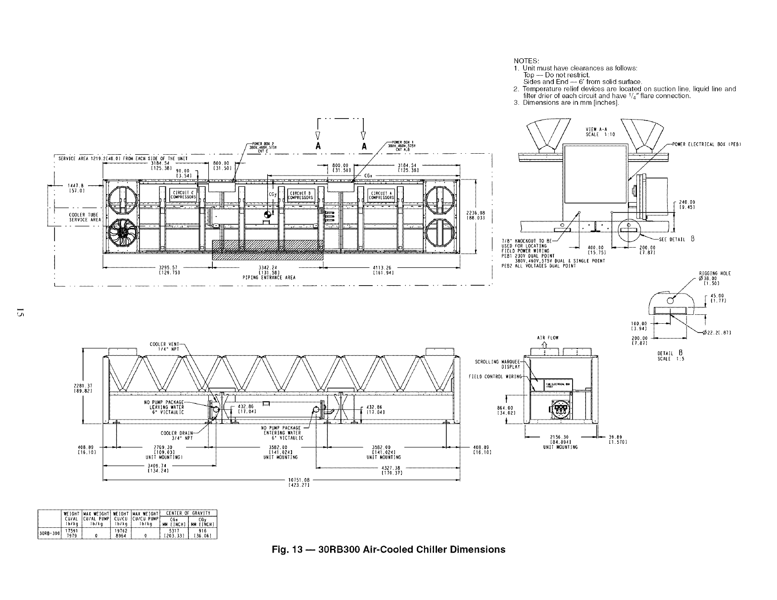
NOTES:
1. Unit must have clearances as follows:
Top -- Do not restrict.
Sides and End -- 6" from solid surface.
2. Temperature relief devices are located on suction line, liquid line and
filter drier of each circuit and have 1/4" flare connection.
3. Dimensions are in mm [inches]•
r
?
Po_ Box z_Ee Box i
_;0,4;o_..... A A ..............
KY,_,B
SERVICE A_EA 1219 R[48 O) FRO_I EACff SIDE OF TXE UNIT /
l" 318151 --
[I75.381 9000 _ 80000 3181 51
[31 501 [125 381
/
............ !3.:2l_..! .......... ,¢...............:...........................a
-- 14478
[Br.o)
.[ COOLER TUBE
SERVICE AREA
L_
I _ _//'/4
- 329557 )
[_20 ?Sl
I
CG)
M
V//////'////_
3312 24
[131 88)
PIPING ENTRANCE AREA
_///////////_ ,,[
•'1 ,, 111326
II6t 04]
7V,E, A-A
SCALE I:I0
24000
19451
228137
180821
40889
I16.I0)
COOLERVENT
NO PUNP PACRAGE
LEAVtR8 WATER
_ COOLER DBAIN_,
3/4 _ NPT
7760 30 ,,
I10003]
UNIT MOURT]NGi
3400¸74
[134¸741
ONIT MOORTING UNIT MOUNTING
-1377,38
{17o3r)
10751,08
[423211
7/8" _MOOWOUT
USE8 FOR LOCArlNG 20000
FIELD POWER WIRING (15751 17871
PEBI ?30V DUAL POiNI
380V•IOOV,S75V DUAL _ SINGLE POINT
PE82 ALL VOLTAGESDUAL POINT
ELECTRICAL BOX (PEB)
AIR FLOW
(i 11 i )
SCROLLING kiAROUE E_
DISPLAY "_
FIEL8 CONTROL WIRING '_X_
V--
86t 00
134.071
?15630 _L 39 89
[81.8941 [I 5701
40889 UNIT MOUNTING
(16.I01
RIGGING HOLE
_ ¢38 O0
1150]
I"o° [1771
I00.00_
13941 2221871
?00.00
[787]
DETAIL
SCALE 1:5
CENTER or GRAVITY
Fig. 13 -- 30RB300 Air-Cooled Chiller Dimensions

UNIT
30RB
O6O
070
O8O
O9O
100
110
120
130
150
UNIT
30RB
160
170
UNIT
30RB
190
210
225
250
275
3OO
Units Without Pumps -- English
MOUNTING WEIGHT (Ib)
No Pump AI/Cu*
ABCD Total
806 856 1138 1072 3872
829 878 1219 1151 4077
913 895 1251 1276 4335
1095 1328 1778 1466 5667
1109 1362 1884 1535 5890
1211 1368 1891 1674 6144
1535 1550 2125 2104 7315
1544 1665 2315 2147 7671
1798 1762 2477 2527 8564
MOUNTING WEIGHT (Ib) No Pump AI/Cu*
A B C D E F Total
996 2055 1041 1423 2795 1345 9655
1033 2086 1045 1427 2912 1487 9990
MOUNTING WEIGHT (Ib) No Pump AI/Cu*
IA B C D E F G H Total
1031 1298 1393 1038 1419 1911 1844 1467 11,402
841 1676 1984 853 1311 2872 2324 1157 13,018
871 1709 1989 855 1313 2877 2452 1283 13,351
1070 2119 1979 850 1307 2863 3019 1544 14,752
627 2086 2631 1292 1866 3634 2984 1080 16,199
899 2418 2617 1284 1859 3621 3455 1435 17,590
UNIT
,_uiID
O60
O70
O80
090
100
110
120
130
150
UNIT
30RB
180
170
UNIT
30RB
190
210
225
250
275
30O
MOUNTING WEIGHT (Ib)
No Pump C_Cut
A B C D Total
929 980 1255 1190 4354
951 1002 1337 1269 4560
1036 1018 1369 1393 4817
1278 1515 1952 1646 6391
1291 1550 2058 1715 6614
1395 1555 2066 1853 6868
1751 1766 2331 2311 8159
1789 1913 2549 2384 8635
2045 2008 2713 2763 9528
MOUNTING WEIGHT (Ib) No Pump Cu/Cut
A B C D E F Total
1142 2364 1203 1582 3089 1481 10,861
1180 2394 1207 1586 3207 1623 11,196
MOUNTING WEIGHT (Ib) No Pump Cu/Cut
A B C D E F G H Total
1194 1506 1601 1200 1578 2106 2039 1625 12,849
943 1917 2255 978 1427 3126 2564 1255 14,465
973 1950 2260 981 1429 3131 2693 1381 14,798
1232 2425 2249 976 1423 3117 3316 1704 16,441
732 2371 3018 1501 2059 4011 3262 1175 18,129
1064 2766 3005 1494 2053 3998 3790 1591 19,761
LEGEND
AI 1 Aluminum
Cu 1 Copper
*Condenser Coil: Aluminum Fins/Copper Tubing.
tCondenser Coil: Copper Fins/Copper Tubing.
UNIT
ounD
060
O7O
080
09O
100
110
120
130
150
UNIT
30RB
160
170
UNIT
30RB
190
210
225
250
275
30O
UNIT
_u_D
060
070
080
09O
100
110
120
130
150
UNIT
30RB
180
170
UNIT
30RB
190
210
225
250
275
30O
Units Without Pumps -- Sl
MOUNTING WEIGHT (kg)
No Pump AI/Cu*
A B CDTo_l
366 388 516 486 1756
376 398 553 522 1849
414 406 568 579 1966
497 602 806 665 2571
503 618 855 696 2672
549 621 858 759 2787
696 703 964 955 3318
700 755 1050 974 3480
815 799 1124 1146 3885
MOUNTING WEIGHT(kg) No Pump AI/Cu*
A B C D E F Total
452 932 472 645 1268 610 4379
469 946 474 647 1321 675 4531
MOUNTING WEIGHT (kg)No Pump AVCu*
A B C D E F G H Total
468 589 632 471 644 867 836 666 5172
381 760 900 387 595 1303 1054 525 5905
395 775 902 388 596 1305 1112 582 6056
485 961 898 386 593 1299 1369 700 6691
284 946 1193 586 846 1648 1354 490 7348
408 1097 1187 583 843 1642 1567 651 7979
MOUNTING WEIGHT (kg)
No Pump CWCut
A B CDTo_l
421 444 569 540 1975
432 455 607 576 2068
470 462 621 632 2185
580 687 885 747 2899
586 703 934 778 3000
633 705 937 840 3115
794 801 1057 1048 3701
811 868 1156 1081 3917
928 911 1230 1253 4322
MOUNTING WEIGHT(kg) No Pump Cu/Cut
A B C D E F Total
518 1072 546 717 1401 672 4927
535 1086 548 719 1455 736 5078
MOUNTING WEIGHT(kg) No Pump Cu/Cut
A B C D E F G H Total
542 683 726 544 716 955 925 737 5828
428 870 1023 444 647 1418 1163 569 6561
442 885 1025 445 648 1420 1222 627 6712
559 1100 1020 443 645 1414 1504 773 7457
332 1075 1369 681 934 1819 1479 533 8223
483 1255 1363 678 931 1814 1719 722 8964
30RB060-150
cooler
NOTE: Corner weights are calculated at mount-
ing locations. Refer to Fig. 2-13 (certified draw-
ings) for mounting locations.
30RB160-170, 315A, 315B, 330A, 330B,
345A, 345B, 360B
c B A
cooler
D
D
30RB190-300, 360A, 390A, 390B
cooler
D C
Compressors
F G
Fig. 14 -- Unit Weights
16

Single Pump Units -- English Single Pump Units -- SI
UNIT
ourtD
O60
O7O
O80
090
100
110
120
130
150
UNIT
30RB
160
170
UNIT
30RB
190
MOUNTING WEIGHT (Ib)
Single Pump AI/Cu*
A B C D Total
1022 1070 1174 1121 4387
1044 1093 1256 1200 4593
1123 1102 1292 1318 4835
1289 1551 1817 1510 6167
1302 1586 1923 1579 6390
1455 1575 1899 1755 6684
1732 1805 2204 2115 7855
1737 1923 2391 2160 8210
2045 2042 2563 2567 9216
MOUNTING WEIGHT (Ib) Single Pump AI/Ou*
A B C D E F Total
1126 2452 1041 1423 3025 1241 10,308
1169 2477 1045 1427 3148 1378 10,643
MOUNTING WEIGHT (Ib) Single Pump AI/Ou*
A B C D E F G H Total
1031 1420 1798 1038 1419 2085 1796 1467 12,055
UNIT
ourtD
O60
O7O
080
090
100
110
120
130
150
UNIT
30RB
160
170
UNIT
30RB
190
MOUNTING WEIGHT (kg)
Single Pump AI/Cu*
A B C D Total
463 486 533 508 1990
473 496 570 544 2083
510 500 586 598 2193
585 704 824 685 2797
591 719 872 716 2898
660 714 861 796 3032
785 819 1000 959 3563
788 872 1084 980 3724
928 926 1162 1164 4180
MOUNTING WEIGHT (kg) Single Pump AI/Cu*
A B C D E F Total
511 1112 472 645 1372 563 4676
530 1124 474 647 1428 625 4828
MOUNTING WEIGHT (kg) Single Pump AI/Cu*
A B C D E F G H Total
468 644 816 471 644 946 815 666 5468
UNIT
OUND
060
07O
060
090
100
110
12O
130
150
UNIT
30RB
160
170
UNIT
30RB
190
MOUNTING WEIGHT (Ib)
Single Pump Cu/Cut
A B C D Total
1145 1194 1292 1239 4,869
1167 1216 1374 1318 5,075
1247 1225 1410 1435 5,317
1473 1738 1992 1688 6,891
1485 1773 2098 1758 7,114
1640 1761 2075 1933 7,408
1947 2021 2410 2321 8,699
1982 2171 2625 2397 9,175
2292 2288 2799 2803 10,181
MOUNTING WEIGHT (Ib) Single Pump Cu/Out
A B C D E F Total
1313 2788 1207 1586 3440 1516 11,849
1270 2763 1203 1582 3317 1380 11,514
MOUNTING WEIGHT (Ib) Single Pump Cu/Cut
A B C D E F G H Total
1194 1629 2005 1200 1578 2281 1991 1625 13,502
LEGEND
AI -- Aluminum
Cu -- Copper
*Condenser Coil: Aluminum Fins/Copper Tubing.
tCondenser Coil: Copper Fins/Copper Tubing.
UNIT
O60
O70
080
090
100
110
120
130
150
UNIT
30RB
160
170
UNIT
30RB
190
MOUNTING WEIGHT (kg)
Single Pump Cu/Cut
ABCD Total
519 542 586 562 2209
529 552 623 598 2302
566 556 640 651 2412
668 788 904 766 3126
674 804 952 797 3227
744 799 941 877 3360
883 917 1093 1053 3946
899 985 1191 1087 4162
1039 1038 1269 1271 4618
MOUNTING WEIGHT (kg) Single Pump Cu/Cut
A B C D E F Total
576 1253 546 717 1505 626 5223
595 1264 548 719 1560 688 5375
MOUNTING WEIGHT (kg) Single Pump Cu/Cut
A B C D E F G H Total
542 739 909 544 716 1035 903 737 6124
Dual Pump Units -- English Dual Pump Units -- SI
UNIT
ourtD
06O
07O
060
090
100
110
12O
13O
15O
UNIT
30RB
16O
170
UNIT
30RB
190
MOUNTING WEIGHT (Ib)
Dual Pump APCu*
A B C D Total
1155 1202 1197 1150 4705
1177 1225 1279 1229 4911
1302 1276 1327 1353 5258
1453 1740 1851 1546 6590
1466 1775 1957 1616 6813
1631 1719 1908 1810 7067
1869 1987 2258 2124 8238
1872 2107 2443 2171 8593
2267 2297 2639 2605 9808
MOUNTING WEIGHT (Ib) Dual Pump AI/Cu*
A B C D E F Total
1270 2854 1045 1427 3339 1301 11,235
1221 2834 1041 1423 3211 1169 10,900
MOUNTING WEIGHT (Ib) Dual Pump AI/Cu*
10A1 14B8 21198 10D8 14_9 22_0 17G5 14H7 1_,°16_
UNIT
ourtD
O60
O70
080
090
100
110
120
130
150
UNIT
30RB
160
170
UNIT
30RB
190
MOUNTING WEIGHT (kg)
Dual Pump AI/Cu*
ABCDTotal
524 545 543 522 2134
534 556 580 558 2228
590 579 602 614 2385
659 789 840 701 2989
665 805 887 733 3090
740 780 865 821 3206
848 901 1024 963 3737
849 956 1108 985 3898
1028 1042 1197 1181 4449
MOUNTING WEIGHT (kg) Dual Pump AI/Ou*
A B C D E F Total
554 1286 472 645 1456 530 4944
576 1294 474 647 1515 590 5096
MOUNTING WEIGHT (kg) Dual Pump AI/Cu*
A B C D E F G H Total
468 680 997 471 644 1002 810 666 5737
UNIT
OUND
060
07O
060
090
100
110
120
130
150
UNIT
30RB
160
170
UNIT
30RB
190
MOUNTING WEIGHT (Ib)
Dual Pump Cu/Cut
ABCDTotal
1278 1326 1315 1268 5,187
1300 1348 1397 1347 5,393
1425 1399 1445 1471 5,740
1638 1926 2027 1724 7,314
1650 1961 2132 1794 7,537
1815 1904 2084 1987 7,791
2084 2203 2464 2331 9,082
2118 2355 2678 2408 9,558
2513 2544 2875 2841 10,773
MOUNTING WEIGHT (Ib) Dual Pump Cu/Cut
A B C D E F Total
1413 3164 1207 1586 3631 1439 12,441
1366 3144 1203 1582 3504 1307 12,106
MOUNTING WEIGHT (Ib) Dual Pump Cu/Cut
A B C D E F G H Total
1194 1709 2402 1200 1578 2409 1977 1625 14,094
LEGEND
AI -- Aluminum
Cu -- Copper
*Condenser Coil: Aluminum Fins/Copper Tubing.
tCondenser Coil: Copper Fins/Copper Tubing.
UNIT
O60
O70
O80
090
100
110
120
130
150
UNIT
30RB
160
170
UNIT
30RB
190
MOUNTING WEIGHT (kg)
Dual Pump Cu/Cut
ABCDTotal
580 601 597 575 2353
590 612 634 611 2446
646 635 655 667 2604
743 873 919 782 3318
748 890 967 814 3419
824 864 945 901 3534
945 999 1118 1057 4120
961 1068 1215 1092 4335
1140 1154 1304 1289 4887
MOUNTING WEIGHT (kg) Dual Pump Cu/Cut
A B C D E F Total
619 1426 546 717 1589 593 5491
641 1435 548 719 1647 653 5643
MOUNTING WEIGHT (kg) Dual Pump Cu/Cut
A B C D E F G H Total
542 775 1089 544 716 1093 897 737 6393
Fig. 14-- Unit Weights (cont)
]7

Table 2A -- Physical Data, 30RB060-300 -- English
UNIT 30RB
OPERATING WEIGHT (Ib)*
AI-Cu Condenser Coil
Cu-Cu Condenser Coil
REFRIGERANT TYPE
Refrigerant Charge (Ib)
Ckt A]Ckt B/Ckt C
COMPRESSORS
Quantity
Speed (rpm)
(Qty) Compressor Nominal
Capacity (ton) Ckt A
(Qty) Compressor Nominal
Capacity (ton) Ckt B
(Qty) Compressor Nominal
Capacity (ton) Ckt C
Oil Charge (Pt, Ckt A/Ckt B/Ckt C)
No. Capacity Steps
Standard
Optional (Maximum)
Minimum Capacity Step (%)
Standard
Optional
Capacity (%)
Ckt A
CktB
Ckt C
COOLER
Weight (empty, Ib)
Net Fluid Volume (gal)
Maximum Refrigerant Pressure (psig)
Maximum Fluid Side Pressure
Without Pumps (psig)
Maximum Fluid Side Pressure
With Pumps (psig)
FLUID CONNECTIONS (in.)
Inlet and Outlet, Victaulic
Drain (NPT)
CONDENSER FANS
Standard Low Noise Type
Fan Speed (rpm) Standard/Low Noise
No. Blades...Diameter (in.)
No. Fans (Ckt A/Ckt B/Ckt C)
Total Airflow (cfm)
CONDENSER COILS
No. Coils (Ckt A/Ckt B/Ckt C)
Total Face Area (sq ft)
No. Rows (Ckt A or B or C)
Max Working Refrigerant Pressure (psig)
HYDRONIC MODULE (Optional)
Pump
CHASSIS DIMENSIONS (if-in.)
Length
Width
Height
I 060 070 080 090 100 110 120 130 150
4705 4911 5258 6590 6813 7067 8238 8593 9,808
5187 5393 5740 7314 7537 7791 9082 9558 10,773
R-410A, EXV Controlled System
395/4o5/-1112/4o5/-1685/685/-I96/76/-- 198/96/_196/106/--I 96/133/--1133/106/--I 133/133/--
3I3I4I4 5 I6I6
(2) 20
(1) 20
N/A
26.2/13.1/--
33
22
67
33
N/A
715
28.2
445
300
150
(2) 25
(1) 20
N/A
26.2/13.1/--
3
4
29
19
71
29
N/A
715
28.2
445
300
150
4
3/4
4
3/4
1140 1140
9...30 9...30
3/1/-- 3/1/--
49,600 49,600
(2) 20
(2) 20
N/A
26.2/26.2/--
4
5
25
16
5O
5O
N/A
(2) 25
(2) 20
N/A
26.2/26.2/--
22
14
Scroll, Hermetic
I 4 I 5 I
3500
(2) 25 (2) 25
(2) 25 (3) 20
N/A N/A
26.2/26.2/-- 26.2/39.4/--
4 5
5 6
25 18
18 12
50 45
50 55
N/A N/A
56
44
N_
Direct Expansion, Shell and _be _pe
856 856 856 970 970
31.3 31.3 31.3 45.8 45.8
445 445 445 445 445
300 300 300 300 300
150 150 150 150 150
444 66
_4 _4 _ _
Shrouded Axial _pe, _rtical Discharge
1140 1140 1140 1140 I
9,,,30 9.-30 9...30 9...30 I
2/2/-- 3/3/-- 3/3/-- 3/3/--
49,600 74,400 74,400 74,400
_4-in. OD, Plate Fin, Enhanced Copper _bing
94 141 141 141 164
333 33
656 656 656 656 656
Pump(s) with pressure_emperature taps and combination valve.
Single or Dual, 1800 or 3600 rpm
(2) 25
(3) 25
N/A
26.2/39.4/--
5
6
2O
14
4O
6O
N/A
(3) 25 (3) 25
(3) 20 (3) 25
N/A N/A
39.4/39.4/-- 39.4/39.4/--
6 6
7 7
15 17
10 12
56 50
44 50
N/A N/A
3/1/-- 3/1/--
94 94
3 3
656 656
970 1518
45.8 73.5
445 445
300 300
150 150
6 6
3& _4
1140 I 1140 I 1140
9...30 9...30 9...30
3/4/-- 4/4/-- 4/4/--
86,800 99,200 99,200
I 4/4/-- I 4/4/--
188 188
3 3
656 656
7-11 I11-10 I15-9
7-42%2
7-67/16
LEGEND
AI -- Aluminum
Cu -- Copper
EXV -- Electronic Expansion Valve
N/A -- Not Applicable
*Operating weight includes 2 pumps on Models 30RB060-190. No pumps are available on models larger than 30RB190.
18

Table 2A -- Physical Data, 30RB060-300 -- English (cont)
UNIT 30RB
OPERATING WEIGHT (Ib)*
AI-Cu Condenser Coil
Cu-Cu Condenser Coil
REFRIGERANT TYPE
Refrigerant Charge (Ib)
Ckt A]Ckt B/Ckt C
COMPRESSORS
Quantity
Speed (rpm)
(Qty) Compressor Nominal
Capacity (ton) Ckt A
(Qty) Compressor
Capacity (ton) Ckt B
(Qty) Compressor
Capacity (ton) Ckt C
Oil Charge (Pt, Ckt A/Ckt B/Ckt C)
No. Capacity Steps
Standard
Optional (Maximum)
Minimum Capacity Step (%)
Standard
Optional
Capacity (%)
Ckt A
CktB
Ckt C
COOLER
Weight (empty, Ib)
Net Fluid Volume (gal)
Maximum Refrigerant Pressure (psig)
Maximum Fluid Side Pressure
Without Pumps (psig)
Maximum Fluid Side Pressure
With Pumps (psig)
FLUID CONNECTIONS (in,)
Inlet and Outlet, Victaulic
Drain (NPT)
CONDENSER FANS
Standard Low Noise Type
Fan Speed (rpm) Standard/Low Noise
No. Blades,..Diameter (in.)
No. Fans (Ckt A/Ckt B/Ckt C)
Total Airflow (cfm)
CONDENSER COILS
No. Coils (Ckt A/Ckt B/Ckt C)
Total Face Area (sq ft)
No. Rows (Ckt A or B or C)
Max Working Refrigerant Pressure (psig)
HYDRONIC MODULE (Optional)
Pump
CHASSIS DIMENSIONS (ft-in.)
Length
Width
Height
LEGEND
AI -- Aluminum
Cu -- Copper
EXV -- Electronic Expansion Valve
N/A -- Not Applicable
160 170 190 210 225 250 275 300
10,900 11,235 12,647 13,018 13,351 14,752 16,199 17,590
12,106 12,441 14,094 14,465 14,798 16,441 18,129 19,761
R-410A, EXV Controlled System
162/106/-I162/133/-I162/162/-1133/106/1331133/133/1331133/133/1621162/162/1331162/162/162
(4) 25
(3) 20
N/A
52.5/39.4/--
7
8
13
8
62
38
N/A
Scroll, Hermetic
I7I8I9 315009 I10 I11 I 12
(4) 25
(4) 25
N/A
52.5/52.5/--
8
9
13
9
50
50
N/A
(3) 25 (4) 25
(3) 25 (4) 25
(4) 25 (3) 25
39.4/39.4/52.5 52.5/52.5/39.4
10 11
11 12
10 9
7 7
30 36
30 36
40 28
(3) 25 (3) 25
(3) 20 (3) 25
(3) 25 (3) 25
39.4/39.4/39.4 39.4/39.4/39.4
9 9
10 10
10 11
6 8
36 33
28 33
36 33
Direct Expansion, Shell and Tube Type
2382
86.6
445
300
150
666
3/4 3/4 3/4
Shrouded Axial Type, Vertical Discharge
I 1140 1140 1140
9..,30 9...30 9,,,30
4/4/4 4/4/4 4/4/6
(4) 25
(3) 25
N/A
52.5/39.4/--
7
8
14
10
57
43
N/A
(4) 25
(4) 25
(4) 25
52.5/52.5/52.5
12
13
33
33
33
1518 1518 1518 2382 2382 2382 2382
73.5 73.5 73.5 86.6 86.6 86.6 86.6
445 445 445 445 445 445 445
300 300 300 300 300 300 300
150 150 150 150 150 150 150
6 6 6 6 6
3/4 3/4 3/4 3/4 3/4
1140 1140 1140 1140 1140
9...30 9...30 9...30 9...30 9...30
6/4/-- 6/4/-- 6/6/-- 6/6/4 6/6/6
124,000 124,000 148,800 148,800 148,800 173,600 198,400 223,200
3/4-in. OD, Plate Fin, Enhanced Copper Tubing
6/4/-- 6/4/-- 6/6/-- 4/4/4 4/4/4 4/4/6 6/6/4 6/6/6
235 235 282 282 282 328 375 422
3 3 3 3 3 3 3 3
656 656 656 656 656 656 656 656
Pump(s) with pressure/temperature taps
and combination valve.
Single or Dual, 1800 or 3600 rpm Not available
19-8 I 23-7 I 27-6 I 31-5 I 35-4
7-425/32
7-67/16
*Operating weight includes 2 pumps on Models 30RB060-190. No pumps are available on models larger than 30RB190.
19
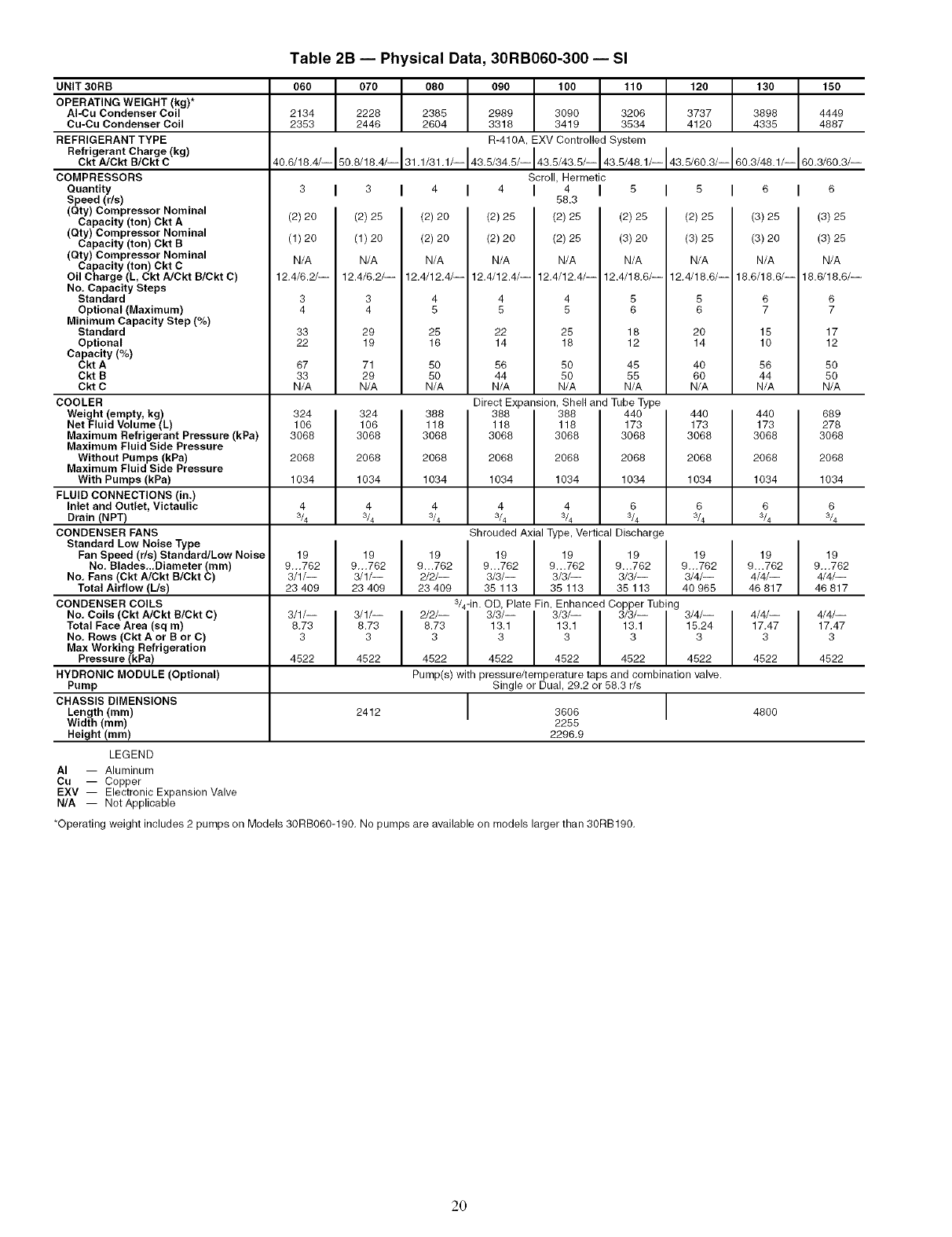
Table 2B -- Physical Data, 30RB060-300 -- Sl
UNIT 30RB
OPERATING WEIGHT (kg)*
AI-Cu Condenser Coil
Cu-Cu Condenser Coil
REFRIGERANT TYPE
Refrigerant Charge (kg)
Ckt A/Ckt B/Ckt C
COMPRESSORS
Quantity
Speed (r/s)
(Qty) Compressor Nominal
Capacity (ton) Ckt A
(Qty) Compressor Nominal
Capacity (ton) Ckt B
(Qty) Compressor Nominal
Capacity (ton) Ckt C
Oil Charge (L Ckt NCkt B/Ckt C)
No, Capacity Steps
Standard
Optional (Maximum)
Minimum Capacity Step (%)
Standard
Optional
Capacity (%)
Ckt A
CktB
Ckt C
COOLER
Weight (empty, kg)
Net Fluid Volume (L)
Maximum Refrigerant Pressure (kPa)
Maximum Fluid Side Pressure
Without Pumps (kPa)
Maximum Fluid Side Pressure
With Pumps (kPa)
FLUID CONNECTIONS (in.)
Inlet and Outlet, Victaulic
Drain (NPT)
CONDENSER FANS
Standard Low Noise Type
Fan Speed (r/s) Standard/Low Noise
No. Blades_.Diameter (ram)
No. Fans (Ckt A]Ckt B/Ckt C)
Total Airflow (L/s)
CONDENSER COILS
No. Coils (Ckt A/Ckt B/Ckt C)
Total Face Area (sq m)
No, Rows (Ckt A or B or C)
Max Working Refrigeration
Pressure (kPa)
HYDRONIC MODULE (Optional)
Pump
CHASSIS DIMENSIONS
Length (ram)
Width (mm)
Height (mm)
LEGEND
AI -- Aluminum
Cu -- Copper
060 070 080 090 100 110 120 130 150
2134 2228 2385 2989 3090 3206 3737 3898 4449
2353 2446 2604 3318 3419 3534 4120 4335 4887
R-41OA, EXV Controlled System
40,6/18,4/-1808/184/-131,1/31,1/-143,8/348/-143,8/43,8/-1438/48,1/-143,8/803/-1803/481/-180,3/803/-
Scroll, Hermetic
I 3 I 4 I 4 I 4 I 8 I
58.3
(2) 25 (2) 20 (2) 25 (2) 25 (2) 25
(1) 20 (2) 20 (2) 20 (2) 25 (3) 20
N/A N/A N/A N/A N/A
12.4/6,2/-- 12,4/12.4/-- 12.4/12.4/-- 12,4/12.4/-- 12.4/18,6/--
3444 5
45 556
29 25 22 25 18
19 16 14 18 12
71 50 56 50 45
29 50 44 50 55
N/A N/A N/A N/A N/A
3
(2) 20
(1)20
N/A
12.4/6.2/--
3
4
33
22
67
33
N/A
324 324 388
106 106 118
3068 3068 3068
2068 2068 2068
1034 1034 1034
444
3/4 _4 _4
Direct Expansion, ShellandTubeType
388
118
3068
2068
1034
4 4 6
_4 3& 3&
Shrouded Axial Type, Vertical Discharge
I 9 19 19
9...762 9...762 9...762
3/3/-- 3/3/-- 3/3/--
35 113 35 113 35 113
I
19 19 I 19
9...762 9...762 I 9...762
3/1/-- 3/1/-- 2/2/--
23 409 23 409 23 409
3/1/--
8.73
3
3/1/--
8.73
3
4522 I
8 I 6
(2) 25 (3) 25
(3) 25 (3) 20
N/A N/A
12,4/18.6/-- 18.6/18._--
5 6
6 7
20 15
14 10
40 56
60 44
N/A N/A
440 440
173 173
3068 3068
2068 2068
1034 1034
6 6
3/4 3&
388 440
118 173
3068 3068
2068 2068
1034 1034
19 19
9,.,762 9...762
3/4/-- 4/4/--
40 965 46 817
4/4/--
17.47
3
EXV -- Electronic Expansion Valve
N/A -- Not Applicable
3/4-in. OD, Plate Fin, Enhanced Copper Tubing
2/2/-- I 3/3/-- 3/3/-- 3/3/-- 3/4/--
8.73 I 13.1 13.1 13.1 15.24
33333
4522 4522 4522 4522 4522
Pump(s) with pressure/temperature taps and combination valve.
Single or Dual, 29.2 or 58.3 r/s
I 3808 I
2255
2296,9
4522
2412 4800
4522
*Operating weight includes 2 pumps on Models 30RB060-190, No pumps are available on models larger than 30RB190,
I 6
(3) 25
(3) 25
N/A
18._18.6/--
6
7
17
12
50
50
N/A
689
278
3068
2068
1034
6
3/4
19
9...762
4/4/--
46 817
4/4/--
17.47
3
4522
20

Table 2B -- Physical Data, 30RB060-300 -- SI (cont)
UNIT 30RB
OPERATING WEIGHT (kg)*
AI-Cu Condenser Coil
Cu-Cu Condenser Coil
REFRIGERANT TYPE
Refrigerant Charge (kg)
Ckt A/Ckt B/Ckt C
COMPRESSORS
Quantity
Speed (r/s)
(Qty) Compressor Nominal
Capacity (ton) Ckt A
(Qty) Compressor Nominal
Capacity (ton) Ckt B
(Qty) Compressor Nominal
Capacity (ton) Ckt C
Oil Charge (L, Ckt A/Ckt B/Ckt C)
No. Capacity Steps
Standard
Optional (Maximum)
Minimum Capacity Step (%)
Standard
Optional
Capacity (%)
Ckt A
Ckt B
Ckt C
COOLER
Weight (empty, kg)
Net Fluid Volume (L)
I160 170 190 210 225 250 275 300
4944 5097 5737 5905 6056 6691 7348 7979
5491 5643 6393 6561 6712 7457 8223 8964
R-41OA, EXV Controlled System
73.5/48.1/--173.5/60.3/- 173.5/73.5/- 160.3/48.1/60.3160.3/60.3/60.3160.3/60.3/73.5173.5/73.5/60.3173.5/73.5/73.5
(4) 25
(3) 25
N/A
24.8/18.6/--
Scroll, Hermetic
7 I 8 I 9&8.3 9
(3) 25
(3) 20
(3) 25
18.6/18.6/18.6
(4) 25
(4) 25
N/A
24.8/24.8/--
8
9
13
9
50
50
N/A
9
10
10
6
(3) 25
(3) 25
(3) 25
18,6/18.6/18,6
9
10
I lO I11 I 12
(3) 25
(3) 25
(4) 25
18.6/18.6/24.8
10
11
10
7
(4) 25
(3) 20
N/A
24.8/18.6/--
7
8
13
8
62
38
N/A
57 38 33 30
43 28 33 30
N/A 36 33 40
Direct Expansion, Shell and Tube Type
689 689 689 1080 1080 1080 1080 1080
278 278 278 327 327 327 327 327
Maximum Refrigerant Pressure (psig) 3068 3068 3068 3068 3068 3068 3068 3068
Maximum Fluid Side Pressure
Without Pumps (psig) 2068 2068 2068 2068 2068 2068 2068 2068
Maximum Fluid Side Pressure
With Pumps (psig) 1034 1034 1034 1034 1034 1034 1034 1034
FLUID CONNECTIONS (in.)
Inlet and Outlet, Victaulic 6 6 6 6 6 6 6 6
Drain (NPT) 3/4 3/4 3/4 3/4 3/4 3/4 3/4 3/4
CONDENSER FANS Shrouded Axial Type, Vertical Discharge
Standard Low Noise Type I
Fan Speed iris) Standard/Low Noise 19 I19 19 19 19 19 19 19
No, Blades.,.Diameter (mm) 9...762 9...762 9...762 9...762 9...762 9...762 9...762 9..,762
No, Fans (Ckt NCkt B/Ckt C) 6/4/-- 6/4/-- 6/6/-- 4/4/4 4/4/4 4/4/6 6/6/4 6/6/6
Total Airflow (L/s) 56 521 58 521 70 226 70 226 70 226 81 930 93 634 105 339
CONDENSER COILS 3/4-in. OD, Plate Fin, Enhanced Copper Tubing
No. Coils (Ckt A/Ckt B/Ckt C) 6/4/= I6/4/= 6/6/-- 4/4/414/4/4 4/4/6 6/6/4 6/6/6
Total Face Area (sq m) 21,83 21.83 26,2 26.2 26,2 30.47 34.84 39.21
No, Rows (Ckt A or B or C) 3 3 3 3 3 3 3 3
Max Working Refrigeration Pressure (kPa) 4522 4522 4522 4522 4522 4522 4522 4522
HYDRONIC MODULE (Optional) Pump(s) with pressure/temperature taps Not available
and combination valve.
Pump Single or Dual, 29,2 or 58,3 r/s Not available
CH S ,SO,OEN ,ONSI I I I I
Length (mm) 5994 5994 7188 7188 7188 8382 9576 10 770
Width (ram) 255
Height (mm) 2296.9
LEGEND
AI -- Aluminum
Cu -- Copper
EXV -- Electronic Expansion Valve
N/A -- Net Applicable
*Operating weight includes 2 pumps on Models 30RB060-190. No pumps are available on models larger than 30RB190.
(4) 25 (4) 25
(4) 25 (4) 25
(3) 25 (4) 25
24.8/24.8/18.6 24.8/24.8/24.8
11 12
12 13
9 8
7 6
36 33
36 33
28 33
2!

Table 3A -- Physical Data -- 30RB315-390- English
315
10,900/10,900
12,106/12,106
4
162/106
162/106
14
UNIT 30RB
OPERATING WEIGHT (Module A/Module B, Ib)*
Cu-AI Condenser Coil
Cu-Cu Condenser Coil
REFRIGERANT TYPE
Circuits Qty
Refrigerant Charge
Module A Ckt A/Ckt B (Ib)
Module B Ckt A/Ckt B (Ib)
COMPRESSORS
Total Quantity
Speed (rpm)
Module A, (Qty) Compressor Nominal
Capacity (ton) Ckt A
Module A, (Qty) Compressor Nominal
Capacity (ton) Ckt B
Module B, (Qty) Compressor Nominal
Capacity (ton) Ckt A
Module B, (Qty) Compressor Nominal
Capacity (ton) Ckt B
Module A Oil Charge (Pt, Ckt A/Ckt B)
Module B Oil Charge (Pt, Ckt A/Ckt B)
No. Capacity Steps
Standard
Optional (Maximum)
Minimum Capacity Step (%)
Standard
Optional
Capacity (%)
Module A, Ckt A
Module A, Ckt B
Module B, Ckt A
Module B, Ckt B
COOLER
Module A Weight (empty, Ib)
Module B Weight (empty, Ib)
Net Fluid Volume (gal) Module A/Module B
Maximum Refrigerant Pressure (psig)
Maximum Fluid Side Pressure (psig)
FLUID CONNECTIONS (in.)
Inlet and Outlet, Victaulic
Drain (NPT)
CONDENSER FANS
Standard Low Noise Type
Fan Speed (rpm) Standard/Low Noise
Module A No. Blades._Diameter (in.) Ckt A/Ckt B
Module B No. Blades...Diameter (in.) Ckt A/Ckt B
Total No. Fans
Module A No. Fans (Ckt A/Ckt B)
Module B No. Fans (Ckt A/Ckt B)
Total Airflow (cfm)
CONDENSER COILS
Module A No. Coils (Ckt A/Ckt B)
Module B No. Coils (Ckt A/Ckt B)
Total Face Area (sq ft)
No. Rows (Ckt A or B, any module)
Max Working Refrigerant Pressure (psig)
LEGEND
AI -- Aluminum
Cu -- Copper
EXV -- Electronic Expansion Valve
(4) 25
(3) 20
(4) 25
(3) 20
52.5/39.4
52.5/39.4
14
16
31
19
31
19
330 345 360
11,235/10,900 11,235/11,235 12,647/11,235
12,441/12,106 12,441/12,441 14,094/12,441
R-410A, EXV Controlled System
4I4 4
162/133 I162/133 162/162
162/106 162/133 162/133
Scroll, Hermetic
14 I 14 I 15
3500
(4) 25
(3) 25
(4) 25
(3) 20
52.5/39.4
52.5/39.4
14
16
(4) 25 (4) 25
(3) 25 (4) 25
(4) 25 (4) 25
(3) 25 (3) 25
52.5/39.4 52.5/52.5
52.5/39.4 52.5/39.4
14 15
16 17
7 7
6 5
29 27
21 27
29 27
21 20
390
12,647/12,657
14,094/14,094
4
162/162
162/162
I16
(4) 25
(4) 25
(4) 25
(4) 25
52.5/52.5
52.5/52.5
30
22
30
18
Direct Expansion, ShellandTubeType
1518 I 1518 1518
1518 I1518 1518
73.5/73.5 73.5/73.5
445 445
300 300
16
18
25
25
25
25
*No pumps are available for models 30RB315-390.
1518 1518
1518 1518
73.5/73.5 73.5/73.5 73.5/73.5
445 445 445
300 300 300
6 6
3/4 I I 3/46I6I6
3& 3/4 3/4
Shrouded Axial Type, Vertical Discharge
1140 1140 1140
9_.30/9...30 9_.30/9_.30 9_.30/9_.30
9...30/9...30 9...30/9_.30 9...30/9_.30
20 20 22
6/4 6/4 6/6
6/4 6/4 6/4
248,000 248,000 272,800
3&-in. OD, Plate Fin, Enhanced Copper Tubing
6/4 I 6/4 6/6
6/4 I6/4 6/4
470 470 517
3 3 3
656 656 656
1140
9_.30_._30
9...30_...30
20
6_
6_
248,000
6/4
6/4
470
3
656
1140
9._30/9_.30
9...30/9...30
24
6/6
6/6
297,600
6/6
6/6
564
3
656
22

Table 3B -- Physical Data -- 30RB315-390 -- Sl
I 315 390
4944/4944 5737/5737
5491/5491 6393/6393
4 4
73,5/48,1 73,5/73.5
73.5/48.1 73.5/73.5
14
UNIT 30RB
OPERATING WEIGHT (Module A/Module B, kg)*
Cu-AI Condenser Coil
Cu-Cu Condenser Coil
REFRIGERANT TYPE
Circuits Qty
Refrigerant Charge
Module A Ckt A/Ckt B (kg)
Module B Ckt A/Ckt B (kg)
COMPRESSORS
Total Quantity
Speed (r/s)
Module A, (Qty) Compressor Nominal
Capacity (ton) Ckt A
Module A, (Qty) Compressor Nominal
Capacity (ton) Ckt B
Module B, (Qty) Compressor Nominal
Capacity (ton) Ckt A
Module B, (Qty) Compressor Nominal
Capacity (ton) Ckt B
Module A Oil Charge (L, CktA/CktB)
Module B Oil Charge (L, CktA/CktB)
No. Capacity Steps
Standard
Optional (Maximum)
Minimum Capacaity Step (%)
Standard
Optional
Capacity (%)
Module A, Ckt A
Module A, Ckt B
Module B, Ckt A
Module B, Ckt B
COOLER
Module A Weight (empty, kg)
Module B Weight (empty, kg)
Net Fluid Volume (L) Module A/Module B
Maximum Refrigerant Pressure (kPa)
Maximum Fluid Side Pressure (kPa)
FLUID CONNECTIONS (in.)
Inlet and Outlet, Victaulic
Drain (NPT)
CONDENSER FANS
Standard Low Noise Type
Fan Speed (r/s) Standard/Low Noise
Module A No. Blades...Diameter (mm.) Ckt A/Ckt B
Module B No. Blades...Diameter (mm.) Ckt A/Ckt B
Total No. Fans
Module A No. Fans (Ckt A/Ckt B)
Module B No. Fans (Ckt A/Ckt B)
Total Airflow (L/s)
CONDENSER COILS
Module A No. Coils (Ckt A/Ckt B)
Module B No. Coils (Ckt A/Ckt B)
Total Face Area (sq m)
NO. Rows (Ckt A or B, any module)
Max Working Refrigerant Pressure (kPa)
LEGEND
AI -- Aluminum
Cu -- Copper
EXV -- Electronic Expansion Valve
(4) 25
(3) 20
(4) 25
(3) 20
52.5/39.4
52.5/39.4
14
16
31
19
31
19
330 345 360
5096/4944 5096/5096 5737/5096
5643/5491 5643/5643 6393/5643
R-410A, EXV Controlled System
4 I 4 4
735/60.3 173.5/60.3 735/735
73.5/48.1 73.5/60.3 73.5/60.3
Scroll, Hermetic
14 I 14 I 15
58.3
(4) 25
(3) 25
(4) 25
(3) 20
52.5/39.4
52.5/39.4
(4) 25
(3) 25 (4) 25
(4) 25
(4) 25
(3) 25
52.5/52.5
52.5/39.4
I 16
(4) 25
(3) 25
52.5/39.4
52.5/39.4
14 14 15
16 16 17
677
465
30 29 27
22 21 27
30 29 27
18 21 20
Direct Expansion, Shell and Tube Type
689 I 689 689
689 I 689 689
278/278 278/278 278/278
3068 3068 3068
2068 2068 2068
666
3/4 3/4 3/4
Shrouded Axial Type, Vertical Discharge
19 19 19
9...762/9...762 9...762/9_ .762 9_.762/9_.762
9._762/9...762 9...762/9_ .762 9._762/9_.762
20 20 22
6/4 6/4 6/6
6/4 6/4 6/4
117 042 117 042 128 747
3/4-in. OD, Plate Fin, Enhanced Copper Tubing
6/4 I 6/4 6/6
6/4 I6/4 6/4
43.66 43.66 48.03
333
4522 4522 4522
(4) 25
(4) 25
(4) 25
(4) 25
52.5/52.5
52.5/52.5
16
18
*No pumps are available for models 30RB315-390.
25
25
25
25
689 689
689 689
278_78 278/278
3068 3068
2068 2068
6 6
3/4 3/4
19
9_.762_._762
9...762__.762
20
6_
6_
117 042
6_
6_
43.66
3
4522
19
9_.762/9...762
9...762/9._762
24
6/6
6/6
140 452
6/6
6/6
52.4
3
4522
23
INSTALLATION
Storage -- If tile unit is to be stored for a period of time
before installation or stall-up, be sure to protect the machine
from construction dirt and moisture. Keep protective shipping
covers in place until machine is ready for inst;fllation.
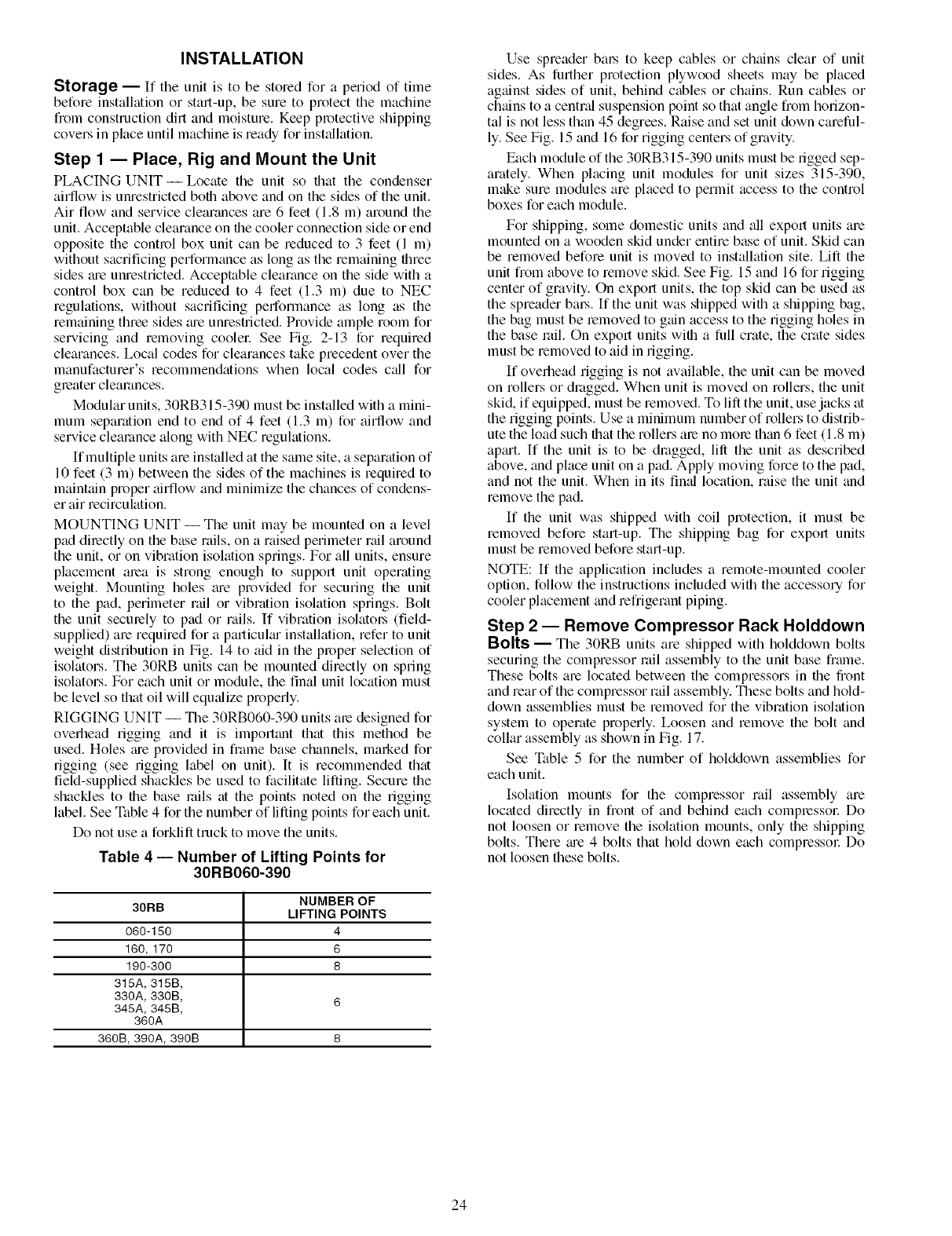
Step 1 -- Place, Rig and Mount the Unit
PLACING UNIT--Locate the unit so that the condenser
airflow is unrestricted both above and on the sides of the unit.
Air flow and service clearances are 6 feet (1.8 m) around the
unit. Acceptable clealance on the cooler connection side or end
opposite the control box unit can be reduced to 3 feet (1 m)
without sacrificing performance as long as the remaining three
sides tue unrestricted. Acceptable clearance on the side with a
control box can be reduced to 4 feet (1.3 m) due to NEC
regulations, without sacrificing performance as long as the
remaining three sides tue unrestricted. Provide ample room for
servicing and removing coolel: See Fig. 2-13 for required
clearances. Local codes for clearances take precedent over the
manufacturer's recommendations when local codes c_dl for
greater clearances.
Modular units, 30RB315-390 must be installed with a mini-
mum separation end to end of 4 feet (1.3 m) for aiNow and
service clearance along with NEC regulations.
If multiple units are installed at the same site, a separation of
10 feet (3 m) between the sides of the machines is required to
maintain proper airflow and minimize the chances of condens-
er air recirculation.
MOUNTING UNIT -- The unit may be mounted on a level
pad directly on the base rails, on a raised perimeter nfil around
the unit, or on vibration isokition springs. For all units, ensure
placement area is strong enough to support unit operating
weight. Mounting holes tu'e provided for securing the unit
to the pad, perimeter rail or vibration isolation springs. Bolt
the unit securely to pad or rails. If vibration isolatol_ (field-
supplied) are required for a particulm installation, refer to unit
weight distribution in Fig. 14 to aid in the proper selection of
isolators. The 30RB units can be mounted directly on spring
isolators. For each unit or module, the final unit location must
be level so that oil will equ_dize properly.
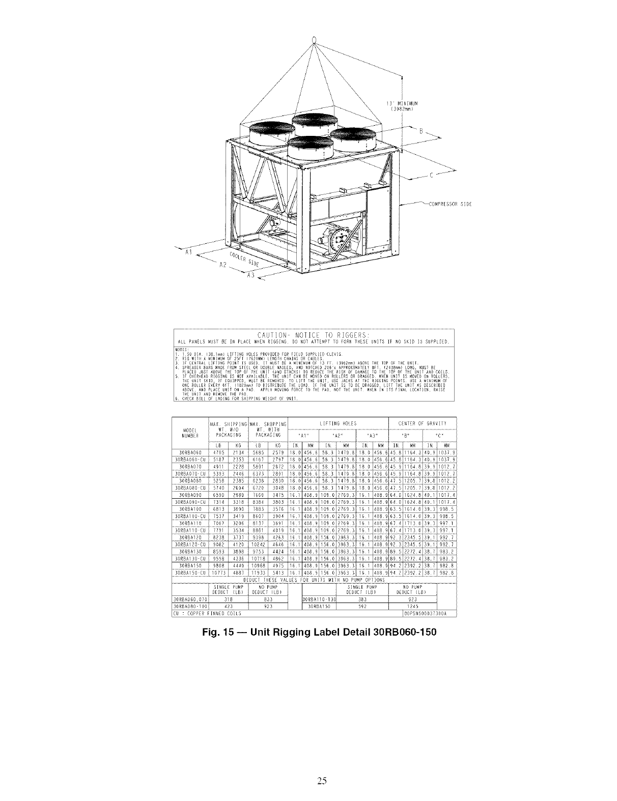
RIGGING UNIT -- The 30RB060-390 units are designed for
ovefllead rigging and it is importtmt that this method be
used. Holes tue provided in frame base channels, marked for
rigging (see rigging label on unit). It is recommended that
fiekl-supplied shackles be used to facilitate lifting. Secure the
shackles to the base mils at the points noted on the rigging
label. See Table 4 for the number of lifting points for each unit.
Do not use a forklift truck to move the units.
Table 4 -- Number of Lifting Points for
30RB060-390
NUMBER OF
30RB LIFTING POINTS
060-150 4
160,170 6
190-300 8
315A, 315B,
330A, 330B, 6
345A, 345B,
360A
360B, 390A, 390B 8
Use spreader bm_ to keep cables or chains clear of unit
sides. As further protection plywood sheets may be placed
against sides of unit, behind cables or chains. Run cables or
chtfins to a central suspension point so that angle from horizon-
tal is not less than 45 degrees. Raise and set unit down careful-
ly. See Fig. 15 and 16 for rigging centers of gravity.
Each module of the 30RB315-390 units must be rigged sep-
arately. When placing unit modules for unit sizes 315-390,
m_e sure modules are placed to permit access to the control
boxes for each module.
For shipping, some domestic units and all export units are
mounted on a wooden skid under entire base of unit. Skid can
be removed before unit is moved to installation site. Lift the
unit from above to remove skid. See Fig. 15 and 16 for rigging
center of gravity. On export units, the top skid can be used as
the spreader bm_. If the unit was shipped with a shipping bag,
the bag must be lemoved to gtfin access to the rigging holes in
the base rail. On export units with a full crate, the crate sides
must be removed to aid in rigging.
If overhead rigging is not available, the unit can be moved
on rollers or dmggedi When unit is moved on rollers, the unit
skid, if equipped, must be removed. To lift the unit, use jacks at
the rigging points. Use a minimum number of rollers to distrib-
ute the load such that the rollers are no mole than 6 feet (1.8 m)
aptut. If the unit is to be dragged, lift the unit as described
above, and place unit on a pad. Apply moving force to the pad,
and not the unit. When in its fired location, raise the unit and
remove the pad.
If the unit was shipped with coil protection, it must be
removed before start-up. The shipping bag for export units
must be removed before start-up.
NOTE: If the application includes a remote-mounted cooler
option, follow the instructions included with the accessoly for
cooler placement and refrigerant piping.
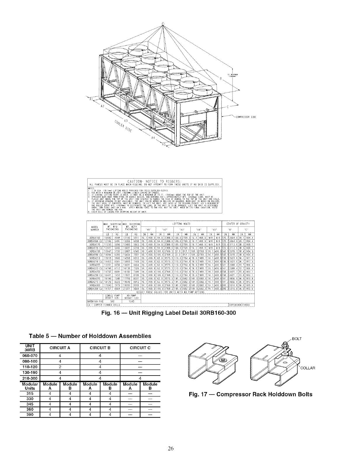
Step 2 -- Remove Compressor Rack Holddown
Bolts -- The 30RB units are shipped with holddown bolts
securing the compressor rail assembly to the unit base frmne.
These bolts are located between the compressors in the front
and rear of the compressor rail assembly. These bolts and hold-
down assemblies must be removed for the vibration isolation
system to operate properly. Loosen and remove the bolt and
collar assembly as shown in Fig. 17.
See Table 5 for the number of holddown assemblies for
each unit.
Isolation mounts for the compressor rail assembly are
located directly in front of and behind each compressol: Do
not loosen or remove the isolation mounts, only the shipping
bolts. There tue 4 bolts that hold down each compressol: Do
not loosen these bolts.
24
!3" MINIMUN
(3982mm)
S:D6
MAX SIIIPPING _AX SHIPPING LIFTING HOLES C_NIER OF GRAVIIY
MODEL WT WIT_
NUMOER PACKAGING
30RBA050 4705 2134 5505 2579 100 455¸6 503 1479¸0 100 1455¸6 450 1164¸3!40¸9 1037¸9
SGRSAO58 C_ 5/07 2353 5!57 2797 /0 0 456 6 58 S 14790 180 14566 450 11543!489 1037 9
3090A018C0 5393 2446 6313 2891 18 0 456 4 08 3 1479 8 :812 7
.... o4s66
30ROA080CO 5[40 9504 5T90 3048 10 O 4556 58 3 14798
30RBA080 6590 2989 7660 0475 151 400£ 1090 27593
30ROAOG CU 7314 3310 0304 3003 16/ 4000 /090 27693 151 4009 540 16248140110174
30RBAI80 5013 3090 7883 5676 15 / 4009 !050 27593 151 4009 535 151401383 9985
39o 4o
320£ #13!
30113AllOCU 7/91 3534 0861 4019 16 1 400 £ 109 0 27593 161 400 9 674 3/13 01393 9921
0_#_ 373 L4_& !_Z 408 I 15 408 2}92 5
30RBAI20 C8 9002 4120 10242 4646 101 4009 1550 S9553 151 4009 923 23455}381 9927
30RBAISO 8595 3090 8753 4424 16/ 400£ /560 39653 161 4009 885 227241387 9852
30RBA!38 C_ 9558 4335 10710 4062 :6/ 4002 !560 39533 151 4009 095 297241307 9032
DEDUCT IHESE VALUES FOR UNITS WITH NO PUMP OP/]ONS
2U : COPPER FINNED CO:LS IOOPSNSOOO37308A
Fig. 15- Unit Rigging Label Detail 30RB060-150
25
CAUTION- NOTICE TO RIGGERS:
L!FTI_G HOLES C[NT[R OF GRAVITY
_A4
....iTI- _ .....
_CT THESE VALU_:SFOR UNitS W[IH NO P_MP O?TIONS
Fig. 16- Unit Rigging Label Detail 30RB160-300
Table 5 -- Number of Holddown Assemblies
UNIT
3ORB
060-070
080-100
110-120
130-190
210-300
Modular
Units
315
330
345
360
390
CIRCUIT A
4
4
2
4
4
Module Module
A B
4 4
4 4
4 4
4 4
4 4
CIRCUIT B
4
4
4
4
4
Module Module
A B
4 4
4 4
4 4
4 4
4 4
CIRCUIT C
4
Module Module
A B
_IOLLAR
Fig. 17 -- Compressor Rack Holddown Bolts
26

Step 3 -- Cooler Fluid and Drain Piping Con-
nections -- The 30RB units are supplied with a factory-
installed flow switch in the leaving water (fluid) piping. Flow
switch wiring is factory installed.
To facilitate servicing it is recommended additional field-
supplied air vents be installed to facilitate servicing. Ix_cate air
vents at the highest possible point of the chilled water system.
In addition to field-supplied air vents, facilitate servicing in ad-
dition to flow bfdancing by instfflling field-supplied shut-off
valves, thermometers, clean-out tees, plessure and temperature
taps in the inlet and outlet piping. Locate valves in return and
supply cooler water lines as close to the chiller as possible.
In sound sensitive applications, consider the installation of
piping vibration isolators.
FREEZE PROTECTION- Upon completion of the field
piping installation, freeze protection must be considered.
Freeze protection for the cooler is av;dlable fi_m the factory
wifll a freeze protection option for the unit. Freeze protection
for the pump (hydronic) package is standard on fdl units with
the optionfd hydronic package (30RB060-190 units). Externfd
piping freeze protection also must be considered. Since power
is sometimes lost for extended periods during winter storms,
fieeze protection provided by heater tapes will be effective
only if a back-up power supply can be assured for the unit's
control circuit, heater and cooler pump. If not protected with
an antifreeze solution, draining the cooler and outdoor piping
is recommended if the system will not be used during freezing
weather conditions.
NOTE: See page 39 for a more detailed overview of freeze
protection.
IMPORTANT: Glycol anti-freeze solutions are highly
recommended since heater tapes provide no protection
in the event of a power failure
UNITS WITH HYDRONIC PUMP PACKAGE -- The
30RB060-190 units can be equipped with a factory-installed
hy&'onic pump package consisting of a suction guide/strainer.
pump, combination vfdve, internal piping and wiring con-
nected at the factory.
The combination vfdve performs the following functions:
•Drip-tight shut-off valve
• Spring closure design with a non-slam check valve
•Flow-throttling valve
When facing the cooler side of unit, the inlet (return) water
connection is on the right. The outlet (supply) water connection
is on the left. The inlet is connected to the suction guide/
strainer of the pump via a Victaulic-type connection. The cool-
er supply has water-side Victaulic-type connections (follow
connection directions as provided by the coupling manufactur-
er). Provide proper support for the piping. If compressor and
cooler grilles have been added, holes must be cut in the grilles
for field piping and insulation.
The suction guide/strainer is shipped from the factory with a
run-in screen. This screen is a temporary device used during
the stfut-up/clean-up process of file chilled water circuit to
prevent construction debris from damaging the pump or
internal tubes of coolel: After all debris has been removed or a
maximum of 24 running hours the temporary screen must
be removed. See the Start-Up, Controls, Operation and
Troubleshooting guide for further information.
The suction guide/strainer is shipped from the factory with
a ran-in screen. This temponuy screen must be removed
after all debris has been removed or a maximum of 24 run-
ning hours. Failure to remove the temporary screen may
result in dmnage to the pump or cooler
NOTE: It is required that a 20 mesh field-supplied strainer be
installed in the inlet piping to the cooler on open loop systems.
A 3/4 in. Nt_ fitting is installed in the inlet piping of the
pump for connection to an expansion tank. Install the tank in
accordance with the manufacturer's instructions.
Figures 18 and 19 illustrate typical single and dual pump
packages.
Three drain connections me provided and me located fit
leaving water (supply) end of cooler, pump volute, and the
suction guide. See Fig. 2-13 for connection location. Insulate
the drain piping (in the same manner as the chilled water pip-
ing) for at least 1ft (305 mm) from the coolel:
UNITS WITHOUT HYDRONIC PUMP PACKAGE --When
facing the cooler side of the unit, the inlet (return) water con-
nection is on the right. It is required that a field-supplied strain-
er with a minimum size of 20 mesh be installed ahead of the
cooler inlet to prevent debris fi_m &imaging internal tubes of
the coolel: The outlet (supply) water connection is on the left.
The cooler has water-side victaulic-type connections (follow
connection directions as provided by the coupling manufactur-
er). Provide proper support for the piping. If compressor and
cooler grilles have been added, holes must be cut in the grilles
for field piping and insulation. See Fig. 20 for a typical piping
diagrmn of a 30RB unit without a hy&onic pump package.
A drain connection is located fit the leaving water (supply)
end of coolel: See Fig. 2-13 for connection location. Insulate
the drain piping (in the same manner as the chilled water
piping) for fit least 12 in. (305 mm) from the unit.
FOR ALL UNITS
Dual Chiller Leaving Water Sensor -- If the Dual Chiller
fdgorithm is used, and the machines are installed in pandlel, a
dual chilled water sensor must be instfdled for each module.
For 30RB315-390, a factory-supplied thermistor and well are
shipped in the control box of each module. Install the well in
the common leaving water headel: See Fig. 21.
See page 41 for more dufd chiller leaving water sensor
information.
Minimum Loop Volume -- The preferred minimum loop vol-
ume is dependent on the type of application. In order to obt_in
leaving water temperature stability for comfort cooling appli-
cations, a minimum of 3 gallons per ton (3.25 liters per kW) is
required on all unit sizes. For process cooling applications,
applications where high stability is critical, or operation at
alnbient temperatures below 32 F (0 ° C) is expected, the loop
volume should be increased to 6 to 10 gfdlons per ton (6.46 to
10.76 liters per kW) of cooling.
In order to achieve this volume, it may be necessary to add a
water storage tank to the water loop. If a storage tank is added
to the system, it should be properly vented so that the tank can
be completely filled and fdl air eliminated. Failure to do so
could cause lack of pump stability and poor system operation.
Any storage tank that is placed in the water loop should
have internal baffles to allow thorough mixing of the fluid. See
Fig. 22.
System Piping -- Proper system design and installation proce-
dures should be followed closely. The system must be
constructed with pressure tight components and thoroughly
tested for instfdlation leaks. Factory-supplied hydronic systems
me available with single or dual (for back-up) pumps. The
factory-installed system includes all of the components above
the line in Fig. 18 and 19.
Installation of water systems should follow sound engineer-
ing practice as well as applicable local and industry standards.
Improperly designed or instfdled systems may cause unsatis-
factory operation and/or system failure. Consult a water
treatment specialist or appropriate literature for information
regarding filtration, water treatment, and control devices.
Figure 18 shows a typicfd instfdlation with components that
might be installed with the hydronic package of the 30RB unit.
27
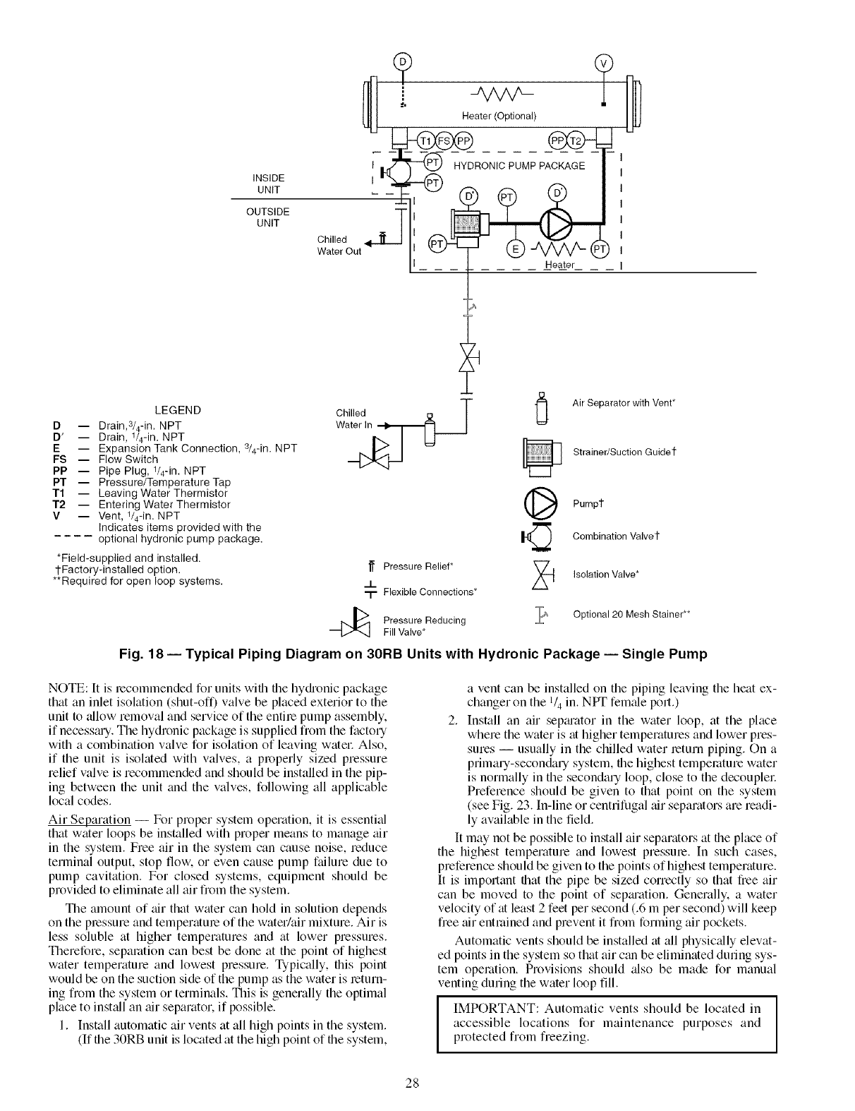
INSIDE
UNIT
OUTSIDE
UNIT
"
[ ........ Heater ....
LEGEND
D -- Drain,3/4-in. NPT
D' -- Drain, 1/4-in. NPT
E -- Expansion Tank Connection, s/4-in. NPT
FS -- Flow Switch
PP -- Pipe Plug, 1/4-in. NPT
PT -- Pressure/Temperature Tap
T1 -- Leaving Water Thermistor
T2 -- Entering Water Thermistor
V -- Vent, 1/4-in. NPT
Indicates items provided with the
.... optional hydronic pump package.
*Field-supplied and installed.
1-Factory-installed option.
**Required for open loop systems.
1_ Pressure Relief*
_!_
-I- Flexible Connections*
Pressure Reducing
Fill Valve*
Air Separator with Vent*
Strainer/Suction Guide'l"
Pump1
Combination Valve t
z_ Isolation Valve*
?_ Optional 20 Mesh Stainer**
Fig. 18 -- Typical Piping Diagram on 30RB Units with Hydronic Package -- Single Pump
NOTE: [t is recommended for units with file hy&onic package
that an inlet isolation (shut-off) valve be placed exterior to the
unit to _fllow removal and service of the entire pump assembly.
if necessmy. The hydronic package is supplied from the factory
with a combination valve for isolation of leaving watel: Also,
if the unit is isolated with valves, a properly sized pressure
relief valve is recommended and should be installed in the pip-
ing between the unit and the valves, following all applicable
local codes.
Air Separation -- For proper system operation, it is essential
that water loops be installed with proper means to manage air
in the system. Free air in the system can cause noise, reduce
terminal output, stop flow. or even cause pump failure due to
pump cavitation. For closed systems, equipment should be
provided to eliminate all air fiom the system.
The amount of tfir that water can hold in solution depends
on the pressure and temperature of the water/air mixture. Air is
less soluble at higher temperatures and at lower pressures.
Therefore, separation can best be done at the point of highest
water temperature and lowest pressure. Typically, fills point
would be on the suction side of the pump as the water is return-
ing from the system or terminals. This is generally the optimal
place to inst_fll an air separator, if possible.
1. Install automatic air vents at all high points in the system.
(If the 30RB unit is located at the high point of the system,
a vent can be installed on the piping leaving the heat ex-
changer on the 1/4 in. NPT female port.)
2. Install an air sepm'ator in the water loop, at the place
where the water is at higher temperatures and lower pres-
sures -- usually in the chilled water return piping. On a
primary-secon&lry system, the highest temperature water
is normally in the secondary loop, close to the decouplec
Preference should be given to that point on the system
(see Fig. 23. In-line or centrifugal air separators are readi-
ly available in the field.
It may not be possible to install air separators at the place of
the highest temperature and lowest pressure. In such cases,
preference should be given to the points of highest temperature.
It is impommt flint the pipe be sized correctly so that free air
can be moved to the point of sep_uation. Generally. a water
velocity of at least 2 feet per second (.6 m per second) will keep
free air entrained and prevent it fiom forming air pockets.
Automatic vents should be installed at all physic_dly elevat-
ed points in the system so that air c_m be eliminated dunng sys-
tem operation. Provisions should _flso be made for manual
venting during the water loop till,
IMPORTANT: Automatic vents should be located in
accessible locations for maintenance purposes and
protected from freezing.
28

INSIDE
UNIT
OUTSIDE
UNIT
I
I
I
Chilled j
Water Out
Heater(Optional)
HYDRONIC PUMP PACKAGE
- -i
IHeater
I
J
I
I
I
I
I
I
I
I
I
J
LEGEND
D -- Drain,3/4-in. NPT
D' -- Drain, 1/4-in. NPT
E -- Expansion Tank Connection, 3/4-in. NPT
FS -- Flow Switch
PP -- Pipe Plug, 1/4-in. NPT
PT -- Pressure/Temperature Tap
T1 -- Leaving Water Thermistor
T2 -- Entering Water Thermistor
V -- Vent, 1/4-in. NPT
*Field-supplied and installed.
tFactory-installed option,
**Required for open loop systems.
Chilled _ TAir Separator with Vent*
Strainer/Suction Guide 1-
E_ Reverse Flow Check
Valve/Service Valve t
Service Valvet
Pumps
Pressure Relief* _ Combination Valvet
J_
-r Flexible Connections* Z_ Isolation Valve*
Pressure Reducing
Fill Valve* _ Optional 20 Mesh Stainer**
Fig. 19- Typical Piping Diagram on 30RB Units with Hydronic Package- Dual Pumps
LEGEND
D-- Drain, 3/4-in. NPT
FS -- Flow Switch
PP -- Pipe Plug, 1/4-in. NPT
T1 -- Leaving Water Thermistor
T2 -- Entering Water Thermistor
V -- Vent, 1/4-in. NPT
Heater(Optional)
Chilled Water
Out ChilledlnWater _l
Fig. 20 -- Typical Piping Diagram on 30RB Units without Hydronic Package
29

I
I
I
Ir-
I€
II
L _-
v
D
D
m -H-
©©©
Master Chiller
-H
©©©
©©©
Slave Chiller
--H
©©©
Control
Box
Pump and Check Valve
or Isolation Valve
I
I
I ! Control
Box
d
Pump and Check Valve
or Isolation Valve
Dual Chiller
LWT Sensors
and Wells
LEGEND
LWT -- Leaving Water (fluid) Temperature
+ Field Wiring
*_ Field Communication Wiring
NOTE: This isa simplified piping diagram -- not all hydronic specialties are shown.
Fig. 21 -- Dual Chiller Thermister Location
Tank Installation
BAD GOOD
BAD GOOD
Fig. 22 -- Tank Baffling
30

il L
Decoupler _
Distribution Pump
Expansion
Tank(s)
Air Separator
with Vent
N1
NOTE: Expansion tanks for 30RB hydronic kits must be installed for chillers piped in parallel in the primary water loop.
Fig. 23 -- Typical Air Separator and Expansion Tank Location on Primary-Secondary Systems
Step 4 -- Fill the Chilled Water Loop
IMPORTANT: Before starting unit, be sure all of tile
air has been purged from the system.
The chilled water pump (if equipped) is rated for 150 psig
(1034 kPa) duty. Tile maximum cooler fluidside plessure is
300 psig (2068 kPa). Check the pressure rating for all of the
chilled water devices installed. Do not exceed file lowest pies-
sure rated device.
WATER SYSTEM CLEANING-- Proper water system
cleaning is of vital importance. Excessive particulates in the
water system can cause excessive pump senti wear. reduce or
stop flow, and cause damage of other components.
1. Install a temporary bypass around the chiller to avoid
circulating dirty water and particulates into the pump
package and chiller during the flush. Use a temporary
circulating pump during the cleaning process. Also, be
sure that there is capability to fully drain the system after
cleaning. See Fig. 24.
2. Be sure to use a cleaning agent that is compatible with
all system materials. Be especi_dly ctueful if the system
contains any galvanized or aluminum components. Both
detergent-dispersant and alkaline-dispersant cleaning
agents me available.
3. It is lecommended to fill the system through a water
metel: This provides a reference point for the future for
loop volume readings, and it also establishes the correct
quantity of cleaner needed in order to reach the required
concentration.
4. Use a feeder/transfer pump to mix the solution and fill the
system. Circulate the cleaning system for the length of
time recommended by the cleaning agent manufacturel:
a. After cleaning, &'ain the cleaning fluid and flush the
system with fresh watel:
b. A slight mnount of cleaning residue in the system can
help keep the desired, slightly alkaline, water pH of 8
to 9. Avoid a pH greater than 10, since this will
adversely affect pump seal components.
c. A side stream filter is recommended (see Fig. 25 dur-
ing the cleaning process. Filter side flow rate should
be enough to tilter the entire water volume evely 3 to
4 hom.s. Change filters as often as necessary during
the cleaning process.
d. Remove temponuy bypass when cleaning is complete.
A suction guide with an internal strainer is standm'd on all
30RB units with factory-installed hy&'onic packages. This
strainer allows removed of particulates from the chilled
water loop. Using the combination v_dve and the field-installed
isolation valve at the inlet, the strainer can be isolated from the
chilled water loop to be cleaned.
The Carrier Conl/brtLink TM controls provided have a built-
in feature to remind building owners or operators to clean the
strainer at a pre-set time interval. Properly inst_flled, cleaned
and maintained systems will rarely need the strainer cleaned
after the initial fill. This time interval is user-configumble.
Ideally, the chilled water loop will be cleaned before the unit
is connected. If the run-in screen is left in the suction guide/
strainer, it is recommended that the Sela_ice Maintenance be set
to alert the operator within 24 hours of start-up to be sure that
the run-in screen in the suction guide/strainer is not removed at
start-up.
NOTE: The suction guide/strainer must be removed after the
first 24 hours of operation.
To set the time for the parameter, go to Time ClocWMCFG/
W.FIL in the Scrolling Marquee or the handheld Navigatol :r_"
display. Values for this item m'e input in days.
SYSTEM
1POT FEEDER AND
DILUTED I TRANSFER PUMP
CLEANING
• - K::/1-4,,
TEMPORARY I /30RB UNIT
PUMP l /
_TE_MPORAR Y
1_ BYPASS
TO DRAIN
Fig. 24 -- Typical Set Up for Cleaning Process
SYSTEM ]
/r1POTFEEDERAND
I--'J_ / DILUTED LTRANSFER PUMP
SIDE [--I V |CLEANING
STREAMI I 4X / AGENT _ I
FILTER U ] [ --J X
T,. TEMPORARY ', /30RB UNIT
PUMP _ /
TO DRAIN
Fig. 25 -- Cleaning Using a Side Stream Filter
31

WATER TREATMENT -- Fill the fluid loop with water (or
brine) and a corrosion-resistant inhibitor suitable for the water
of the mea. Consult the local water treatment specialist for
characteristics of system water and a recommended inhibitor
for the cooler fluid loop.
SYSTEM PRESSURIZATION- A proper initial cold fill
pressure must be established before filling of the unit. The
initial cold fill pressure is the pressure applied at the filling
point to fill a system to its highest point, plus a minimum
pressure at the top of the system (4 psig minimum [27.6 kPa])
to operate air vents and positively pressurize the system. The
expansion tank is veUimportant to system pressurization. The
expansion tank serves several purposes:
1. Provide NPSHR (Net Positive Suction Head Requimd)
for the pump to operate satisfactorily.
2. Set system pressure.
3. Accommodate expansion/contraction of water due to
temperature changes.
4. Acts as a pressure reference for the pump.
The expansion tank pressure must be set BEFORE the
system is filled. Follow the manufactumr's mcommen&_tion
for instructions on setting the pressure in the expansion tank.
NPSHR information is provided on the Pump Curves in
Fig. 26-33 for units with factou-installed hydronic kits. See
Table 6 for pump impeller sizes.
Once the system is pressurized, the pressure at the connec-
tion point of the expansion tank to water piping will not change
unless the water loop volume changes (either due to addition/
subtraction of water or temperatum expansion/contraction).
The pressure at this point remains the same regardless of
whether or not the pump is running.
Since the expansion tank acts as a reference point for the
pump, them cannot be two reference points (two expansion
tanks) in a system, unless manifolded togetheL Where two or
mom 30RB chillers with the hydionic option am installed in
pm'allel, them should not be more than one expansion tank in
the system, unless manifolded together as seen in Fig. 23. It is
permissible to install the expansion tank(s) in a portion of the
return water line that is common to all pumps, providing that
the tank is properly sized for combined system volume.
If the application involves two or mom chillers in a primm-y
seconcktUsystem, a common place for mounting the expan-
sion tank is in the chilled water return line, just befom the
decoupler See Fig. 23 for placement of expansion tank in
primau-seconda Usystems.
If a diaphragm expansion tank is utilized (a flexible
diaphragm physically separates the water/air interface) it is not
recommended to have any air in the water loop. See the section
on air separation on page 28 for instructions on providing air
separation equipment.
FILLING THE SYSTEM- The initial fill of the chilled
water system must accomplish throe goals:
1. The entire piping system must be filled with water
2. The pmssum at the top of the system must be high enough
to vent air from the system (usually 4 psig [27.6 kPal is
adequate for most vents).
3. The pressure at all points in the system must be high
enough to prevent flashing in the piping or cavitation in
the pump.
The pressure created by an operating pump affects system
pressure at all points except one -- the connection of the
expansion tank to the system. This is the only location in the
system whem pump operation will not give erroneous pressure
indications during the fill. Themfom, the best location to install
the fill connection is close to the expansion tank. An air vent
should be installed close by to help eliminate air that enters
during the fill procedure.
When filling the system, ensum the following:
1. Remove temporary bypass piping and cleaning/flushing
equipment.
2. Check to make sure all drain plugs am installed.
Normally, a closed system needs to be filled only once. The
actual filling process is a fairly simple procedum. All air should
be purged or vented from the system. Thorough venting at high
points and circulation at room temperatum for several hours is
highly recommended.
NOTE: Ix_cal codes concerning backflow devices and other
protection of the city water system should be consulted and
followed to prevent contamination of the public water supply.
This is critical when anti-fieeze is used in the system.
Table 6 -- Pump Impeller Sizes
UNIT PUMP SINGLE PUMP
30RB Hp Option Code* Rpm Impeller Dia.(in.)
3 0 1750 6.5
5 1 1750 7.3
060
070 7.5 2 1750 8.15
10 3 3450 5.4
5 1 1750 7.3
080 7.5 2 1750 8.15
090
100 10 3 3450 5.4
15 4 3450 6.1
5 1 1750 7.3
110 7.5 2 1750 8.15
120
130 10 3 3450 5.4
15 4 3450 6.1
5 1 1750 6.5
150
160 7.5 2 3450 4.6
170 10 3 3450 5.0
190 15 4 3450 5.5
Pump Curve
I
I
I
II
I
I
II
II
I
I
II
II
III
IV
IV
IV
DUAL PUMP
Option Code* Rpm Impeller Dia. (in.)
6 1750 6.5
71750 7.3
8 1750 8.15
9 3450 5.25
B 3450 5.9
7 1750 7.3
8 1750 8.15
B 3450 5.4
C 3450 6.1
7 1750 7.3
8 1750 8.15
B 3450 5.4
C 3450 6.1
8 3450 4.6
B 3450 5.0
C 3450 5.5
Pump Curve
V
V
V
Vl
Vl
V
V
VII
VII
V
V
VII
VII
VIII
VIII
VIII
*Option Code refers to the Hydronics Option (position 11) in the model number. See Fig. 1 for
option identification.
NOTE: Pump Selections are chiller size dependent. For example, dual pump "C" on a 30RB170
chiller is not the same as dual pump "C" on a 30RB130 chiller.
32

Head (m) ft i
I
I
(18.3) 60
(14.8) 48
(11.0) 36
(7.3) 24
N '
(3.7) 12 P
S
(o.o) o
iii
iii
i i
75QRRMi,
i
160
80 240 320 400 gpm
(us)
O.OO 5.05 10.09 15.14 20.19 25.24 I/s
Hew Rate
NOTE: Refer to Fig. 1 option identification. Refer to the Pump Impeller Sizes table on page 32 for more information.
Fig. 26 -- Pump Curve I for Hydronic Package Single Pump (Fresh Water)
Head (m) ft
(45.7)
(36.6) 120
(27.4) 90
(18.3) 60
(9.1) 30
(O.O) O
0
0.00
i i
i
139
ii i
i i
345O RPM
100 200 300 400 500 gpm(us)
6.31 12.62 18.93 25.24 31.54 I/s
Flow Rate
NOTE: Refer to Fig. 1 option identification. Refer to the Pump Impeller Sizes table on page 32 for more information.
Fig. 27 -- Pump Curve II for Hydronic Package Single Pump (Fresh Water)
33

48
,'_ 175_) RPM
Head (m) ft
(18.3) 60
(14.6) 48
(11.0) 36
(7.3) 24
(3.7) 12
il
I 35:
I I, 6Z
73
i
S NPSHr ....... ,
r I
(00) 0 ' :..... , i i i i i i i i i
0 160 320 480 640 800 gpm(us)
0.00 10.09 20.19 30.28 40.38 50.47 I/s
Flow Rate
NOTE: Refer to Fig. 1 option identification. Refer to the Pump Impeller Sizes table on page 32 for more information.
Fig. 28 -- Pump Curve III for Hydronic Package Single Pump (Fresh Water)
Head (m) ft
(45.7) 150
(36.6) 120
(27.4) 90
(18.3) 60
(9.1) 30
(o.o) o200
0.00 12.62
i
i
i
i
' '3
, _ :345
400 600 800 1000 gpm(us)
25.24 37.85 50.47 63.09 I/s
Flow Rate
NOTE: Refer to Fig, 1 option identification. Refer to the Pump Impeller Sizes table on page 32 for more information.
Fig. 29 -- Pump Curve IV for Hydronic Package Single Pump (Fresh Water)
34

Head (m) ft
(18.3) 60
(14.6) 48
(11.0) 36
(7.3) 24
I
(3.7) 12
(o.o) o
0.00
• J7.-5 hp
\53
3hD
2 nD
80 160 240 320 400 gpm(us)
5.05 10.09 15.14 20.19 25.24 I/s
Flow Rate
NOTE: Refer to Fig. 1 option identification. Refer to the Pump Impeller Sizes table on page 32 for more information.
Fig. 30 -- Pump Curve V for Hydronic Package Dual Pump (Fresh Water)
Head (m) ft
(45.7) 150
(36.6) 120
(27.4) 90
(18.3) 60
(9.1) 30
(o.o) o
0.00
NOTE: Refer to Fig. option identification. Refer to the Pump Impeller Sizes table on page 32 for more information.
Fig. 31 -- Pump Curve Vl for Hydronic Package Dual Pump (Fresh Water)
35

Head (m) ft
(45.7) 150
(36.6) 120
(27.4) 90
(18.3) 60
(9.1) 30
(0.o) o0 1O0
0.00 6.31
i i
i i i
i
i
i
i
i i
i i
i i i
i
:345J) RRM
200 300 400 500 gpm(us)
12.62 18.93 25.24 31.54 I/s
Flow Rate
NOTE: Refer to Fig. 1 option identification. Refer to the Pump Impeller Sizes table on page 32 for more information.
Fig. 32 -- Pump Curve VII for Hydronic Package Dual Pump (Fresh Water)
Head(m) ft
(45.7) 150
(36._ t£O
(27.4) 90
(18.3)
(9.1) 30
I T
i
i
i i
i i
i i
i
i 42
i J
L J
I /
I i
I I
i I
I
I
i
i
L
I I I
I , I
4 I I
r 345ORPM
i i
i i
i
i i
i i
i i
4i
(o.o) o 200 400 600 800 1000 gpm
(us)
0.00 12.62 25.24 37.85 50.47 63.09 I/s
Flow Rate
NOTE: Refer to Fig. 1 option identification. Refer to the Pump Impeller Sizes table on page 32 for more information.
Fig. 33 -- Pump Curve VIII for Hydronic Package Dual Pump (Fresh Water)
36

SET WATER FLOW RATE -- Once the system is cleaned,
pressurized, and filled, the flow rate through the chiller
needs to be established. On units with the hydronic package,
this can be accomplished by using the balancing valve.
Follow the manufacturer's recommendations for setting the
balancing valve. Local codes may prohibit restricting the
amount of water using the balancing valve for a given motor
horsepowel: In this case, use the method listed in the Pump
Modification/Trimming section. See Table 7 for the type of
Combination Valve in 30RB units with the optional
hydronic package.
Table 7 -- Combination Valve Details
30RB UNIT SINGLE/DUAL PUMP
060-130 FTV-4 in.
150-190 FTV-6 in.
NOTE: CtuTier recommends a differential pressure gage when
measuring pressures across the pumps or balancing valves.
This provides for greater accuracy and reduces error build-up
that often occurs when subtracting pressures made by different
gages.
A rough estimate of water flow can also be obtained from
the pressure gages across the 30RB heat exchangel:
Figure 34-36 shows the relationship between gpm and heat
exchanger pressure drop. It should be noted that these curves
are for fresh water and "clean" heat exchangers; they do not
apply to heat exchangers with fouling. To read the chart,
subtract the readings of the two pressure gages on the hydronic
kit. This number is the pressure drop across the heat exchangel:
Adjust the factory-installed balancing valve or external balanc-
ing valve (in units without hydronic package) until the correct
pressure drop is obtained for the required gpm.
PUMP MODIFICATION/TRIMMING -- Since the pumps
are constant speed, the only way to obtain greater flow with a
given pump/impeller is to decrease system head. This will
allow the pump to "ride" its curve to the fight, resulting in
increased flow. If greater flow is necessary, consider opening
the combination valve. Also, verify that the strainer is clean,
and that no unnecessmy system resistance is present, such as
partially closed isolation valves.
Once the combination valve is set, note the stem position. If
later service work requires the valve to be closed, it will be easier
to m-b_dance the system, if the origimd b_flance point is known.
Increasing system resistance by closing the balancing v_dve
will force the pump to "ride" its curve to the left, resulting in
less flow. Although this does reduce power consumption
slightly, it may not be the desirable method of reducing the
flow. especially if a large reduction is needed.
The other method for reducing flow on a constant speed
pump is impeller trimming. The impellers in the pumps provid-
ed in the 30RB hydronic kit can be easily removed for this
purpose. Refer to the vendor literature packet supplied with the
hy&'onic package information on Senti Replacement in the
Service Section, and follow instructions for impeller removal
and trimming. See Fig. 37-44 for pump envelope curve infor-
mation. Trimming should only be done by a qualified machine
shop that has experience in this operation. Contact your local
C_urier representative for a recommended machine shop.
After trimming, the impeller MUST be balanced. Failure to
balance trimmed impellers can result in excessive vibra-
tion, noise, and premature bearing failure.
Impeller trimming has the added benefit of maximum bhp
(brake horsepower) savings, which can recover the cost
incurred by performing the impeller trimming.
30RB060-130
060, 071 /080, 09 I, 100 J/"
//
/11( 120, 130
///"/
0 100 200 300 400 500 600 700
GPM
6.3 12.6 18.9 25.2 31.5 37.8 4A.2
Us
Fig. 34 -- 30RB060-130
Cooler Pressure Drop Curves
30RB210-300
/
/
/
/
/./
0 100 300 500 700 goo 1100 1300
GPM
63 189 315 442 568 694 82
u_
Fig. 35 -- 30RB210-300
Cooler Pressure Drop Curve
1500
946
30RB150-190 and 30RB315A, B; 330A, B; 345A, B; 360A,B; 390A, B
/
/
J
J
J
0 200 400 600 800 1000
GPM
12.6 25.2 37.8 50.5 63.1
Us
Fig. 36 -- 30RB150-190 and 30RB315A, B; 345A, B;
360A, B; 390A,B Cooler Pressure Drop Curve
37

110(_3m)
90_27m)
6O (18m)
50 _16m)
_40 d2m)
30 _gm)
2O _6m)
10 (3m)
2 "\-,
5O 100 160 2OO 260 _00 36O
GPM
NOTE: Refer to Fig. 1 for pump envelope curve option identification.
Fig. 37 -- 30RB060, 070 --
Single Pump Envelope Curves
140 (42m) 4
120 (_m)
90 (27m)
I 70 (21m)
4o/12,n) ""-"_-_. _. \
20 (6m) _= \
0 5o 100 150 2oo 25o 300 35o 4oo 45o 5oo
GPM
NOTE: Refer to Fig. 1 for pump envelope curve option identification,
Fig. 38 -- 30RB080, 090, 100 --
Single Pump Envelope Curves
14o(4_m)
mo(_)
g?oo (_m)
_(27m)
1o (_)
o
o
NOTE: Refer to Fig. 1 for pump envelope curve option identification.
Fig. 39- 30RBl10, 120, 130-
Single Pump Envelope Curves
110(33m) 4
eo 124m/ "_=
7o(21m)
1
,o,_, -__. \ \ \
o
0 1(30 200 3_O 4(30 50(} 600 700 800
GPM
NOTE: Refer to Fig, 1 for pump envelope curve option identification.
Fig. 40-- 30RB160, 170, 190-
Single Pump Envelope Curves
lS0(4_m)
_40(42_)
120(Se_)
m0 (_0m)
_0(27m)
=7o (21m)
20(6r_)
° o
B_
\
7_
150 2O0 250 300
GPM
NOTE: Refer to Fig. 1 for pump envelope curve option identification.
Fig. 41 -- 30RB060, 070 --
Dual Pump Envelope Curves
_so(4sm)
C
o
0 50 100 150 200 250 300 350 400 450 500
GPM
NOTE: Refer to Fig. 1 for pump envelope curve option identification.
Fig. 42 -- 30RB080, 090, 100 --
Dual Pump Envelope Curves
lS0(4Sm)
C"**'-
_10(33"n) B%'
oo,,oo, ._____..._.
4D (12m)
0
0 50 100 150 200 250 3o0 350 4o0 450 5(30
GPM
NOTE: Refer to Fig. 1 for pump envelope curve option identification.
Fig. 43 -- 30RB110, 120, 130 --
Dual Pump Envelope Curves
_1o{33m) O "
100(30m) _
913(27m) _-
i _"°" \ \'\
_o,o., \.. \ \
o
0 100 200 300 400 500 600 700 800 900
GPM
NOTE: Refer to Fig. 1 for pump envelope curve option identification.
Fig. 44-- 30RB160, 170, 190-
Single Pump Envelope Curves
.38

PREPARATION FOR YEAR ROUND OPERATION --If
the unit is in operation yem-round, add sufficient suitable
inhibited antifreeze solution such as propylene or ethylene
glycol to chilled water to prevent freezing under low-alnbient
operating conditions. Consult local water treatment specialist
on chm'acteristics of water and recommended inhibitor
I IMPORTANT: Glycol anti-freeze solutions are highly
recommended since heater tapes provide no protection
in the event of a power failure.
If the unit is equipped with Motormaster@ control, field-
fabricated and field-installed wind baffles me required if the
wind velocity is anticipated to be greater than 5 mph (8 km/h).
Two different baffles are required, one for the control box end
and one for the opposite control box end. Wind baffles should
be constructed with minimum 18-gage galvanized sheet metal
or other suitable corrosion-resistance material with cross
breaks for strength. Use field-supplied screws to attach baffles
to the comer posts of the machine. Be sure to hem or turn a
flange on all edges to eliminate sharp edges on the baffles.
To avoid possibility of electrical shock, open all discon-
nects be fore installing or servicing this accessory.
To avoid dmnage to the refrigerant coils and electrical com-
ponents, use extreme care when &illing screw holes and
screwing in fasteners.
Mount the smaller height baffle on the control box end. It is
recommended that the upper notches be used for mounting the
baffles. This reduces the risk of dalnaging the coil while drill-
ing a mounting hole. Ix)osen the upper corner post bolts and
slide the baffle under the bolt and washel: Tighten the bolt.
Drill holes in the bottom of the flange of the baffle and mount
with two screws to secure the bottom of the baffle to the corner
post. Repeat the process for the opposite side. See Fig. 45.
FREEZE PROTECTION- The 30RB units are provided
with a flow switch to protect agtfinst freezing situations that
occur fiom no water flow. While the flow switch is helpful in
preventing freezing during no-flow situations, it does not pro-
tect the chiller in case of power failure during sub-freezing
ambient temperatures, or in other cases where water tempera-
ture falls below the freezing maN. Appropriate concentrations
of inhibited propylene or ethylene glycol or other suitable
inhibited antifreeze solution should be considered for chiller
protection where alnbient temperatures me expected to fall
below 32 F (0 ° C). Consult local water treatment specialist on
chmacteristics of the system water and add a recommended
inhibitor to the chilled watel: The Carrier wmranty does not
cover damage due to freezing.
1. If the pump will be subjected to freezing temperatures,
steps must be t_,en to prevent freeze dmnage. If the pump
will not be used during this time, it is recommended to
drain the pump and hydronic package and these compo-
nents me back-flushed with inhibited glycol. Otherwise, a
glycol-water solution should be considered as the heat
transfer fluid. Drains are located on the pump(s) and
suction guide/strainer for units with hydronic kits. Units
without hy&'onic kits have a drain mounted on the bottom
of the heat exchanger nero the leaving water connection of
the heat exchangel:
NOTE: Do not use automobile anti-fieeze, or any other fluid
that is not approved for heat exchanger duty. Only use appro-
priately inhibited glycols, concentrated to provide adequate
protection for the temperature considered.
2. Use an electric tape heater for the external piping, if unit
will be exposed to freezing temperatures.
3. Ensure that power is available to the chiller at _dl times,
even during the off-season, so that the pump and cooler
heaters have power. Also make sure that the piping tape
heaters have powec
4. On units with pump packages, a heater is supplied with
the hydronic package that will protect this section from
freezing in outdoor-air temperatures down to -20 F
(-29 C), except in the case of a power failure. The Carrier
warranty does not cover &_mage due to fieezing.
5. Cooler heaters that will protect components down to
-20 F (-28.9 C) can be ordered as a factoq-installed
option. Again, it should be noted that these heaters will
not protect the cooler from freezing in the event of a
power failure. The Carrier warranty does not cover
damage due to freezing.
PREPARATION FOR WINTER SHUTDOWN -- If the unit
is not operational during the winter months, at the end of cool-
ing season:
Failure to remove power before &'aining heater equipped
coolel_ and hydronic packages can result in heater tape and
insulation &+mage.
1. ff the unit has optional heater tapes on the cooler and the
cooler will not be drained, do not shut off power discon-
nect during off-season shutdown. If the unit has optional
heater tapes on the cooler and the cooler will be drained,
open the circuit breaker for the heater tapes, CB-HT or
shut off power during off-season shutdown.
2. Draining the fluid from the system is highly recommend-
edi If the unit is equipped with a hydronic package, there
me additional drains in the pump housing and strainer
that must be opened to allow for all of the water to drain.
3. Replace the drain plug and add 2 gallons (7.6 liters) of a
suitable corrosion-inhibited anti-freeze solution such as
propylene glycol to the cooler to prevent freezing of any
remaining water in system. Antifreeze can be added
through the vent on top of coolel: If the unit has a hydron-
ic pump package, the pump must also be treated in the
same manneE
4.
5.
Open one of the thermistor connections to allow tdr to
escape the vessel and the anti-freeze to entel:
At the beginning of the next cooling season, be sure that
there is refrigerant pressure on each circuit before
refilling cooler, add recommended inhibitor, and reset the
CB-HT (circuit breaker heater) (if opened) or restore
powec
39

Cross break these faces.
Hem these 3 edges both top
and bottom.
\
See Detail A
y
1880 [74.0] , ,
X
180 [7.0]
305 [12.0]
POSITION BAFFLE HEIGHT (X)
Control/Power End 635 [25.0]
Opposite Control Power End 1040 [41.0]
Material: 18 ga. Corrosion Resistant Sheet Metal.
Dimensions are in mm [inches].
_-18 [0.75]
...........................................21
FAlange_-)s..................................
Detail
Typical Both
Fig. 45 -- Field-Fabricated and Field-Installed Wind Baffles
[1.25]
[0.88]
4O

Step 5 -- Make Electrical Connections
_ [ ELECTRIC SHOCK HAZARD
Open all remote disconnects before servicing
this equipment.
POWER SUPPLY--The electrical characteristics of the
available power supply must agree with the unit nameplate
rating. Supply voltage must be within the limits shown.
Some units have options for multiple power connections.
See Tables 8-12 for electrical requirements and Fig. 46 for
electrical connection information.
IIMPORTANT: Operating unit on improper supply
voltage or with excessive phase imbalance constitutes
abuse and may adversely affect Carrier warranty.
POWER WIRING--All power wiring must comply with
applicable local and national codes. Install field-supplied
branch circuit filsed disconnect per NEC of a type that can be
locked OFF or OPEN. Disconnect must be within sight and
readily accessible fi_)m the unit in compliance with NEC
Article 440-14. In the power box, 7/8 in. holes are provided for
power entry. The holes will need to be enlarged to accept the
appropriate conduit. NEC also requiles all conduits from a
conditioned space to the power box(es) be seared to prevent
airflow and moisture into the control box.
Duplex units require at least two separate power supplies, at
least one for each module, depending on the power supply
option ordered. See Fig. 46.
Genertfl Wiring Notes:
1. The control circuit does NOT requile a sep_uate power
source. A step-down transformer from the main three-
phase power supply obttfins control circuit powec Be sure
that the appropriate connection tap is connected on all
transformel_ for the supply voltage. Up to two termimfl
blocks are provided for field-wired control devices.
2. Cooler and pump heaters (if factory installed) are wired
in the control circuit so they are operable as long as the
main power supply to the unit is ON. A factory-installed
and set overload device protects them.
NOTE: The field-supplied disconnect should never be off
except when unit is being serviced or is to be down for a pro-
longed period, in which case the cooler should be diained.
3. Power entry depends on the size and power entry option
ordered.
4. Maximum field wire sizes allowed by lugs on terminal
block/non-fnsed disconnect _ue listed in Tables 8 and 9.
5. Termimds for field power supply are suitable for copper
conductors. Insulation must be rated 75 C minimum.
IIMPORTANT: To ensure power to the heaters, make
sure power to the unit is always on (except during ser-
vice or a prolonged shutdown).
Proper rotation of condenser fgm(s) and pump(s) MUST be
verified before pumps or compressors are started. Consult
the Controls, Start-Up and Operation guide provided with
30RB060-390 units for correct procedme. Improper pump
rotation can canse permanent dmnage to pump impeller
and housing. If pump(s) have been removed for trimming,
verify wiring is leconnected in the original mannel:
CONTROL POWER -- Control power is obtained from the
main power supply and does NOT require a sep_uate source. A
toggle switch (marked SW2 on the unit label diagram and by
the switch) allows the control circuit to be manu_dly
disconnected when necessaq. Cooler and pump heaters (if
installed) me in an inoperable state when this switch is in the
Off position.
IMPORTANT: For 208-v systems, the connection tap
for all transformers must be changed. The factory
default setting is for 230-v. Failure to connect to the
proper tap may result in unreliable operation.
FIELD CONTROL OPTION WIRING --Install field control
wiring options. See Fig. 46. Some options, such as 4 to 20 mA
Demand Limit that lequiles the Energy Management Module,
may require that accessories be installed filet if not factory
installed for termimd connections.
DUAL CHILLER LEAVING WATER SENSOR -- If the Dual
Chiller _dgorithm is used and the machines are installed in
parallel, an additional chilled water sensor must be inst_dled for
each chiller. For 30RB315-390 units, a factory-supplied ther-
mistor and well are shipped in the control box of each. Install
the well in the common leaving water headel: See Fig 21. DO
NOT lelocate the chiller's leaving water thermistors. They
must remain in place for the unit to operate properly.
The thermistor well is a I/4 in. NPT fitting for securing the
well in the piping. The piping must be drilled and tapped for
the well. Select a location that will allow for removal of the
thermistor without any restrictions. See Fig. 47.
Once the well is inserted, install the thermistors. Insert the
thermistor into the well until the o-ring reaches the well body.
Use the nut on the thermistor to secure the thermistor in place.
Once the thermistor is in place, it is recommended that a
thermistor wire loop be made and secured with a wire tie to the
chilled water pipe. This will aid in thermistor retention in the
well. See Fig. 48.
For 30RB315-390 units, as well as all units using the dual
chiller _dgorithm, a Career Comfort Network (CCN) bus must
be connected between the two modules. See the Carrier
Comfort Network Communication Bus Wiring for additional
information.
41

Table 8 -- 30RB Electrical Data -- Single Point Units
UNIT 30RB
060
070
080
000
100
110
120
130
150
150
170
19O
210
225
250
275
30O
UNIT VOLTAGE
Supplied
V-Hz (3 Ph) MIn Max
208/230-60 187 253
460-60 414 506
575-60 518 633
380-00 342 418
208/230-60 187 253
460-60 414 506
575-60 518 033
380-60 342 418
208/230-60 187 253
400-60 414 506
575-60 518 033
380-00 342 418
208/230-60 187 253
460-60 414 506
575-60 518 033
380-00 342 418
208/230-60 187 253
400-60 414 500
575-60 518 033
380-00 342 418
208/230-60 187 253
400-00 414 506
575-60 518 633
380-00 342 418
208/230-60 187 253
400-60 414 500
575-60 518 033
380-60 342 418
208/230-60 187 253
400-00 414 506
575-60 518 633
380-00 342 418
208/230-60 187 253
460-60 414 506
575-60 518 033
380-00 342 418
208/230-60 187 253
400-60 414 506
575-60 518 033
380-00 342 418
208/230-60 187 253
460-60 414 506
575-60 518 033
380-00 342 418
208/230-60 187 253
400-60 414 500
575-60 518 033
380-00 342 418
208/230-60 187 253
400-60 414 506
575-60 518 033
380-00 342 418
208/230-60 187 253
460-60 414 506
575-60 518 033
380-00 342 418
208/230-60 187 253
400-60 414 500
575-60 518 033
380-00 342 418
208/230-60 187 253
400-60 414 506
575-60 518 033
380-00 342 418
208/230-60 187 253
400-60 414 500
575-60 518 033
380-60 342 418
NO HYDRONIC PACKAGE 3 HP PUM_ 1750 RPM
MCA MOCP ICF Rec Fuse MCA MOCP ICF Rec Fuse
XL XL XL Size XL XL XL Size
291.5 350 682.8 350 302.4 350 693.6 350
127.9 150 302.0 150 132.8 150 306.9 150
102.4 125 244.7 110 106.4 125 248.6 125
150.9 175 362.9 175 156.9 175 368.8 175
334.7 400 777.0 400 345.6 400 787.8 400
147.9 175 355.9 175 152.8 175 360.8 175
119.8 150 287.4 150 123.7 150 291.3 150
175.5 200 428.8 200 181.4 225 434.7 200
366.5 400 757.8 400 ....
160.6 175 334.7 175 ....
128.6 150 270.9 150 ....
189.3 225 401.3 200 ....
433.6 500 875.9 500 ....
191.4 225 399.4 225 ....
154.6 175 322.2 175 ....
226.9 250 480.3 250 ....
472.0 500 914.3 500 ....
209.2 250 417.2 225 ....
170.0 200 337.6 200 ....
248.7 250 502.1 250 ....
508.6 600 950.9 600 ....
224.1 250 432.1 250 ....
180.8 200 348.4 200 ....
265.3 300 518.7 300 ....
590.1 600 1032.3 600 ....
261.6 300 469.6 300 ....
212.5 225 380.2 225 ....
311.1 350 564.5 350 ....
626.7 700 1068.9 700 ....
276.5 300 484.5 300 ....
223.3 250 391.0 250 ....
327.7 350 581.1 350 ....
684.3 700 1126.5 700 ....
303.2 350 511.2 350 ....
246.4 250 414.1 250 ....
360.4 400 613.8 400 ....
744.8 800 1187.0 800 ....
328.9 350 536.9 350 ....
265.9 300 433.5 300 ....
390.1 400 643.5 400 ....
802.4 1000 1244.6 1000 ....
355.6 400 563.6 400 ....
289.0 300 456.6 300 ....
422.8 450 676.2 450 ....
920.5 1000 1362.7 1000 ....
408.0 450 616.0 450 ....
331.5 350 499.1 350 ....
485.2 500 738.5 500 ....
4_9 _o 0_.9 _o Z Z Z Z
342.3 350 509.9 350 ....
501.8 600 755.1 600 ....
4_.0 _o 0_7.6 _o -- -- -- --
365.4 400 533.0 400 ....
534.5 600 787.8 600 ....
5_0 _0 7%.0 _0 Z Z Z Z
408.0 450 575.6 450 ....
596.8 600 850.2 600 ....
5_4 _0 7E.4 _0 Z Z Z Z
450.5 500 618.1 500 ....
659.2 700 912.6 700 ....
8_8 _o 5_.8 _o Z Z Z Z
493.0 500 660.7 500 ....
721.6 800 975.0 800 ....
5HP PUMR 1750 RPM
MCA MOCP ICF Rec Fuse
XL XL XL Size
309.2 350 700.5 350
135.9 150 310.0 150
108.8 125 251.1 125
160.6 175 372.6 175
352.4 400 794.7 400
155.9 175 363.9 175
126.2 150 293.8 150
185.2 225 438.5 200
384.2 450 775.5 450
168.6 200 342.7 200
135.0 150 277.3 150
199.0 225 411.0 225
451.3 500 893.6 500
199.4 225 407.4 225
161.0 175 328.6 175
236.6 250 490.0 250
489.7 500 932.0 500
217.2 250 425.2 250
176.4 200 344.0 200
258.4 300 511.8 300
526.3 600 968.6 600
232.1 250 440.1 250
187.2 200 354.8 200
275.0 300 528.4 300
607.8 700 1050.0 700
269.6 300 477.6 300
218.9 250 386.6 250
320.8 350 574.2 350
644.4 700 1086.6 700
284.5 300 492.5 300
229.7 250 397.4 250
337.4 350 590.8 350
702.0 800 1144.2 800
311.2 350 519.2 350
252.8 300 420.5 300
370.1 400 623.5 400
762.5 800 1204.7 800
336.9 350 544.9 350
272.3 300 439.9 300
399.8 400 653.2 400
820.1 1000 1262.3 1000
363.6 400 571.6 400
295.4 300 463.0 300
432.5 450 685.9 450
938.2 1000 1380.4 1000
416.0 450 624.0 450
337.9 350 505.5 350
494.9 500 748.2 500
LEGEND
ICF -- Instantaneous Current Flow MOCP -- Maximum Overcurrent Protection
MCA -- Minimum Circuit Amps XL -- Across-the-Line Start
NOTES:
1. Units are suitable for use on electrical systems where voltage supplied to the unit
terminals is not below or above the listed minimum and maximum limits. Maximum
allowable phase imbalance is: voltage, 2%; amps 10%.
2. All units/modules have single point primary power connection. (Each unit/module
requires its own power supply.) Main power must be supplied from a field-supplied
disconnect.
3. Cooler heater is wired into the control circuit so it is always operable as long as the
power supply disconnect is on, even if any safety device is open.
4. For MCA that is less than or equal to 380 amps, 3 conductors are required.
For MCA between 381-760 amps, 6 conductors are required.
For MCA between 761-1140 amps, 9 conductors are required.
For MCA between 1141 -1520 amps, 12 conductors are required.
Calculation o1 conductors required is based on 75 C copper wire.
5. Wiring for main field supply must be rated 75 C minimum. Use copper for all units.
a. Incoming wire size range for the terminal block is #4 AWG to 500 kcmN.
b. Incoming wire size range of non-fused disconnect with MCA up to 599.9 amps is
3/0 to 500 kcmil.
c. Incoming wire size range of non-fused disconnect with MCA from 600 to
799.9 amps is 1/0 to 500 kcmil.
d. Incoming wire size range of non-fused disconnect with MCA from 800 to
1199.9 amps is 250 kcmil to 500 kcmil.
6. Hydronic pump packages are not available as a factory-installed option for units
30RB210-390.
7. Power draw includes both crankcase heaters and cooler heaters (where used). Each
compressor has a crankcase heater which draws 56 watts of power. Units ordered with
the cooler heater option have 1 (060-150) or 2 (160-300) cooler heaters, 825 watts
each.
208/230
46O
575 v only
42

Table 8 -- 30RB Electrical Data -- Single Point Units (cont)
UNIT 30RB
A
315
B
A
330
B
A
345
360
390
B
A
B
A
B
UNIT VOLTAGE
Supplied
V-Hz (3 Ph) MIn Max
20_230-60 187 253
460-60 414 506
575-60 518 633
380-60 342 418
20_230-60 187 253
460-60 414 506
575-60 518 633
380-60 342 418
20_230-60 187 253
460-60 414 506
575-60 518 633
380-60 342 418
20_230-60 187 253
460-60 414 506
575-60 518 633
380-60 342 418
20_230-60 187 253
460-60 414 506
575-60 518 633
380-60 342 418
20_230-60 187 253
460-60 414 506
575-60 518 633
380-60 342 418
20_230-60 187 253
460-60 414 506
575-60 518 633
380-60 342 418
20_230-60 187 253
460-60 414 506
575-60 518 633
380-60 342 418
20_230-60 187 253
460-60 414 506
575-60 518 633
380-60 342 418
20_230-60 187 253
460-60 414 506
575-60 518 633
380-60 342 418
NO HYDRONIC PACKAGE 3 HP PUMR 1750 RPM
MCA MOCP ICF Rec Fuse MCA MOCP ICF Rec Fuse
XL XL XL Size XL XL XL Size
744.8 800 1187.0 800 ....
328.9 350 536.9 350 ....
265.9 300 433.5 300 ....
390.1 400 643.5 400 ....
744.8 800 1187.0 800 ....
328.9 350 536.9 350 ....
265.9 300 433.5 300 ....
390.1 400 643.5 400 ....
802.4 1000 1244.6 1000 ....
355.6 400 563.6 400 ....
289.0 300 456.6 300 ....
422.8 450 676.2 450 ....
744.8 800 1187.0 800 ....
328.9 350 536.9 350 ....
265.9 300 433.5 300 ....
390.1 400 643.5 400 ....
802.4 1000 1244.6 1000 ....
355.6 400 563.6 400 ....
289.0 300 456.6 300 ....
422.8 450 676.2 450 ....
802.4 1000 1244.6 1000 ....
355.6 400 563.6 400 ....
289.0 300 456.6 300 ....
422.8 450 676.2 450 ....
920.5 1000 1362.7 1000 ....
408.0 450 616.0 450 ....
331.5 350 499.1 350 ....
485.2 500 738.5 500 ....
802.4 1000 1244.6 1000 ....
355.6 400 563.6 400 ....
289.0 300 456.6 300 ....
422.8 450 676.2 450 ....
920.5 1000 1362.7 1000 ....
408.0 450 616.0 450 ....
331.5 350 499.1 350 ....
485.2 500 738.5 500 ....
920.5 1000 1362.7 1000 ....
408.0 450 616.0 450 ....
331.5 350 499.1 350 ....
485.2 500 738.5 500 ....
5HP PUMP, 1750 RPM
MCA MOCP ICF Rec Fuse
XL XL XL Size
LEGEND
ICF -- Instantaneous Current Flow MOCP -- Maximum Overcurrent Protection
MCA -- Minimum Circuit Amps XL -- Across-the-Line Start
NOTES:
1. Units are suitable for use on electrical systems where voltage supplied to the unit
terminals is not below or above the listed minimum and maximum limits. Maximum
allowable phase imbalance is: voltage, 2%; amps 10%.
2. AN unitdmodules have single point primary power connection. (Each unit/module
requires its own power supply.) Main power must be supplied from a field-supplied
disconnect.
3. Cooler heater is wired into the control circuit so it is always operable as long as the
power supply disconnect is on, even if any safety device is open.
4. For MCA that is less than or equal to 380 amps, 3 conductors are required.
For MCA between 381-760 amps, 6 conductors are required.
For MCA between 761-1140 amps, 9 conductors are required.
For MCA between 1141-1520 amps, 12 conductors are required.
Calculation of conductors required is based on 75 C copper wire.
5. Wiring for main field supply must be rated 75 C minimum. Use copper for all units.
a. Incoming wire size range for the terminal block is #4 AWG to 500 kcmN.
b. Incoming wire size range of non-fused disconnect with MCA up to 599.9 amps is
3/0 to 500 kcmN.
c. Incoming wire size range of non-fused disconnect with MCA from 600 to
799.9 amps is 1/0 to 500 kcmiL
d. Incoming wire size range of non-fused disconnect with MCA from 800 to
1199.9 amps is 250 kcmil to 500 kcmN.
6. Hydronic pump packages are not available as a factory=installed option for units
30RB210-390.
7. Power draw includes both crankcase heaters and cooler heaters (where used). Each
compressor has a crankcase heater which draws 56 watts of power. Units ordered with
the cooler heater option have 1 (060-150) or 2 (160-300) cooler heaters, 825 watts
each.
208/230
46O
575 v only
43

Table 8 -- 30RB Electrical Data -- Single Point Units (cont)
UNIT 30RB
060
070
080
000
100
110
120
130
150
100
170
190
UNIT VOLTAGE 7.5 HP PUMP, 1750/3450 RPM 10 HP PUMP, 3450 RPM 15 HP PUMP, 3450 RPM
Supplied MCA MOCP ICF Rec Fuse MCA MOCP ICF Rec Fuse MCA MOCP ICF Rec Fuse
V-Hz (3 Ph) MIn Max XL XL XL Size XL XL XL Size XL XL XL Size
208/230-60 187 253 317.2 350 708.5 350 325.1 400 716.4 350 ....
460-60 414 506 139.5 150 313.6 150 143.1 175 317.2 175 ....
575-60 518 633 111.7 125 254.0 125 114.6 125 256.9 125 ....
380-60 342 418 165.0 200 376.9 175 169.3 200 381.3 200 ....
208/230-60 187 253 360.4 450 802.7 400 368.3 450 810.6 400 ....
460-60 414 506 159.5 200 367.5 175 163.1 200 371.1 175 ....
575-60 518 633 129.0 150 296.7 150 131.9 150 299.6 150 ....
380-60 342 418 189.5 225 442.8 225 193.9 225 447.2 225 ....
208/230-60 187 253 392.2 450 783.5 450 400.1 450 791.4 450 416.3 450 807.6 450
460-60 414 506 172.2 200 346.3 200 175.8 200 349.9 200 183.1 200 357.2 200
575-60 518 633 137.9 150 280.2 150 140.8 150 283.1 150 146.6 150 288.9 150
380-60 342 418 203.4 225 415.3 225 207.7 225 419.7 225 216.6 250 428.5 250
208/230-60 187 253 459.3 500 901.6 500 467.2 500 909.5 500 483.4 500 925.7 500
460-60 414 506 203.0 225 411.0 225 206.6 225 414.6 225 213.9 250 421.9 225
575-60 518 633 163.9 175 331.5 175 166.8 200 334.4 200 172.6 200 340.2 200
380-60 342 418 241.0 250 494.3 250 245.3 250 498.7 250 254.2 300 507.5 300
208/230-60 187 253 497.7 500 940.0 500 505.6 600 947.9 600 521.8 600 964.1 600
460-60 414 506 220.8 250 428.8 250 224.4 250 432.4 250 231.7 250 439.7 250
575-60 518 633 179.3 200 346.9 200 182.2 200 349.8 200 188.0 200 355.6 200
380-60 342 418 262.8 300 516.1 300 267.1 300 520.5 300 276.0 300 529.3 300
208/230-60 187 253 534.3 600 976.6 600 542.2 600 984.5 600 558.4 600 1000.7 600
460-60 414 506 235.7 250 443.7 250 239.3 250 447.3 250 246.6 250 454.6 250
575-60 518 633 190.1 200 357.7 200 193.0 225 360.6 225 198.8 225 366.4 225
380-60 342 418 279.4 300 532.7 300 283.7 300 537.1 300 292.6 300 545.9 300
208/230-60 187 253 615.7 700 1058.0 700 623.7 700 1065.9 700 639.8 700 1082.1 700
460-60 414 506 273.2 300 481.2 300 276.8 300 484.8 300 284.1 300 492.1 300
575-60 518 633 221.8 250 389.5 250 224.7 250 392.4 250 230.5 250 398.2 250
380-60 342 418 325.2 350 578.5 350 329.5 350 582.9 350 338.4 350 591.7 350
208/230-60 187 253 652.3 700 1094.6 700 660.3 700 1102.5 700 676.4 700 1118.7 700
460-60 414 506 288.1 300 496.1 300 291.7 300 499.7 300 299.0 300 507.0 300
575-60 518 633 232.6 250 400.3 250 235.5 250 403.2 250 241.3 250 409.0 250
380-60 342 418 341.8 350 595.1 350 346.1 350 599.5 350 355.0 400 608.3 400
208/230-60 187 253 709.9 800 1152.2 800 717.9 800 1160.1 800 734.0 800 1176.3 800
460-60 414 506 314.8 350 522.8 350 318.4 350 526.4 350 325.7 350 533.7 350
575-60 518 633 255.7 300 423.4 300 258.6 300 426.3 300 264.4 300 432.1 300
380-60 342 418 374.5 400 627.8 400 378.8 400 632.2 400 387.7 400 641.0 400
208/230-60 187 253 770.4 800 1212.7 800 778.4 800 1220.6 800 794.5 800 1236.8 800
460-60 414 506 340.5 350 548.5 350 344.1 350 552.1 350 351.4 400 559.4 400
575-60 518 633 275.2 300 442.8 300 278.0 300 445.7 300 283.9 300 451.5 300
380-60 342 418 404.1 450 657.5 450 408.5 450 661.9 450 417.3 450 670.7 450
208/230-60 187 253 828.0 1000 1270.3 1000 836.0 1000 1278.2 1000 852.1 1000 1294.4 1000
460-60 414 506 367.2 400 575.2 400 370.8 400 578.8 400 378.1 400 586.1 400
575-60 518 633 298.3 300 465.9 300 301.1 350 468.8 350 307.0 350 474.6 350
380-60 342 418 436.8 450 690.2 450 441.2 450 694.6 450 450.0 500 703.4 500
208/230-60 187 253 946.1 1000 1388.4 1000 954.1 1000 1396.3 1000 970.2 1000 1412.5 1000
460-60 414 506 419.6 450 627.6 450 423.2 450 631.2 450 430.5 450 638.5 450
575-60 518 633 340.8 350 508.4 350 343.7 350 511.3 350 349.5 350 517.1 350
380-60 342 418 499.2 500 752.5 500 503.6 600 756.9 600 512.4 600 765.7 600
LEGEND
ICF -- Instantaneous Current Flow MOCP -- Maximum Overcurrent Protection
MCA -- Minimum Circuit Amps XL -- Across-the-Line Start
NOTES:
1. Units are suitable for use on electrical systems where voltage supplied to the unit
terminals is not bek)w or above the listed minimum and maximum limits. Maximum
alk)wable phase imbalance is: voltage, 2%; amps 10%.
2. All units/modules have single point primary power connection. (Each unit/module
requires its own power supply.) Main power must be supplied from a field-supplied
disconnect.
3. Cooler heater is wired into the control circuit so it is always operable as long as the
power supply disconnect is on, even if any safety device is open.
4. For MCA that is less than or equal to 380 amps, 3 conductors are required.
For MCA between 381-760 amps, 6 conductors are required.
For MCA between 761-1140 amps, 9 conductors are required.
For MCA between 1141 -1520 amps, 12 conductors are required.
Calculation o1 conductors required is based on 75 C copper wire.
5. Wiring for main field supply must be rated 75 C minimum. Use copper for all units.
a. Incoming wire size range for the terminal block is #4 AWG to 500 kcmN.
b. Incoming wire size range of non-fused disconnect with MCA up to 599.9 amps is
3/0 to 500 kcmil.
c. Incoming wire size range of non-fused disconnect with MCA from 600 to
799.9 amps is 1/0 to 500 kcmil.
d. Incoming wire size range of non-fused disconnect with MCA from 800 to
1199.9 amps is 250 kcmil to 500 kcmil.
6. Hydronic pump packages are not available as a factory-installed option for units
30RB210-390.
7. Power draw includes both crankcase heaters and cooler heaters (where used). Each
compressor has a crankcase heater which draws 56 watts o1 power. Units ordered with
the cooler heater option have 1 (060-150) or 2 (160-300) cooler heaters, 825 watts
each.
208/230
46O
575 v only
44

Table 9 -- 30RB Electrical Data -- Dual Point Units
UNIT VOLTAGE NO HYDRONIC PACKAGE 3 HP PUMP, 1750 RPM
UNIT 30RB Supplied Rec Fuse
V-Hz (3 Ph) _ _ MCA MOCP ICF Size
208/230-60 187 253 168.8/141.5 225/200 560.0/532.8 200/175
460-60 414 506 73.6/ 62.5 100/ 90 247.7/236.6 90/ 80
050 575-60 518 633 59.0/ 50.0 80/ 70 201.2/192.3 70/ 60
380-60 342 418 86.4/ 74.1 110/110 298.4/286.1 100/ 90
208/230-60 187 253 212.0/141.5 300/200 579.2/607.8 250/175
070 460-60 414 506 93.6/ 62.5 125/ 90 256.6/281.6 110/ 80
575-60 518 633 76.3/ 50.0 110/ 70 208.9/227.3 90/ 60
380-60 342 418 110.9/ 74.1 150/110 309.3/341.1 125/ 90
208/230-60 187 253 216.5/168.8 250/225 607.8/560.0 250/200
460-60 414 506 95.2/ 73.6 125/100 269.3/247.7 110/ 90
080 575-60 518 633 76.2/ 59.0 100/ 80 218.5/201.2 90/ 70
380-60 342 418 112.5/ 86.4 150/110 324.5/298.4 125/100
208/230-60 187 253 283.6/168.8 350/225 725.9/635.0 350/200
460-60 414 506 126.0/ 73.6 150/100 334.0/292.7 150/ 90
090 575-60 518 633 102.2/ 59.0 125/ 80 269.8/236.2 125/ 70
380-60 342 418 150.1/ 86.4 175/110 403.5/353.4 175/100
208/230-60 187 253 283.6/212.0 350/300 725.9/654.2 350/250
100 460-60 414 506 126.0/ 93.6 150/125 334.0/301.6 150/110
575-60 518 633 102.2/ 76.3 125/110 269.8/243.9 125/ 90
380-60 342 418 150.1/110.9 175/150 403.5/364.3 175/125
208/230-60 187 253 283.6/243.8 350/300 725.9/710.0 350/300
110 460-60 414 506 126.0/106.3 150/125 334.0/325.4 150/125
575-60 518 633 102.2/ 85.2 125/110 269.8/262.4 125/100
380-60 342 418 150.1/124.8 175/150 403.5/391.8 175/150
208/230-60 187 253 259.7/342.0 350/400 702.0/784.2 300/400
120 460-60 414 506 115.2/151.4 150/175 323.2/359.4 150/175
575-60 518 633 93.6/123.1 125/150 261.2/290.8 110/150
380-60 342 418 137.1/179.8 175/225 390.4/433.2 150/200
208/230-60 187 253 401.7/243.8 450/300 843.9/710.0 450/300
460-60 414 506 178.4/106.3 200/125 386.4/325.4 200/125
130 575-60 518 633 144.7/ 85.2 175/110 312.4/262.4 175/100
380-60 342 418 212.5/124.8 250/150 465.9/391.8 225/150
208/230-60 187 253 401.7/306.2 450/400 843.9/748.4 450/350
150 460-60 414 506 178.4/135.2 200/175 386.4/343.2 200/150
575-60 518 633 144.7/110.2 175/125 312.4/277.8 175/125
380-60 342 418 212.5/160.2 250/200 465.9/413.6 225/175
208/230-60 187 253 519.8/243.8 600/300 962.0/710.0 600/300
150 460-60 414 506 230.8/106.3 250/125 438.8/325.4 250/125
575-60 518 633 187.3/ 85.2 200/110 354.9/262.4 200/100
380-60 342 418 274.9/124.8 300/150 528.3/391.8 300/150
208/230-60 187 253 519.8/306.2 600/400 962.0/748.4 600/350
460-60 414 506 230.8/135.2 250/175 438.8/343.2 250/150
170 575-60 518 633 187.3/110.2 200/125 354.9/277.8 200/125
380-60 342 418 274.9/160.2 300/200 528.3/413.6 300/175
208/230-60 187 253 543.7/400.4 600/450 985.9/842.6 600/450
190 460-60 414 506 241.6/176.8 250/200 449.6/384.8 250/200
575-60 518 633 195.9/144.1 225/175 363.5/311.7 225/175
380-60 342 418 288.0/209.5 300/250 541.3/462.9 300/225
208/230-60 187 253 626.7/353.9 700/400 1068.9/796.2 700/400
210 460-60 414 506 276.5/156.8 300/175 484.5/364.8 300/175
575-60 518 633 223.3/127.5 250/150 391.0/295.1 250/150
380-60 342 418 327.7/186.4 350/225 581.1/439.7 350/200
208/230-60 187 253 684.3/353.9 700/400 1126.5/796.2 700/400
460-60 414 506 303.2/156.8 350/175 511.2/364.8 350/175
225 575-60 518 633 246.4/127.5 250/150 414.1/295.1 250/150
380-60 342 418 360.4/186.4 400/225 613.8/439.7 400/200
208/230-60 187 253 684.3/472.0 700/500 1126.5/914.3 700/500
250 460-60 414 506 303.2/209.2 350/250 511.2/417.2 350/225
575-60 518 633 246.4/170.0 250/200 414.1/337.6 250/200
380-60 342 418 360.4/248.7 400/250 613.8/502.1 400/250
208/230-60 187 253 920.5/353.9 1000/400 1362.7/796.2 1000/400
275 460-60 414 506 408.0/156.8 450/175 616.0/364.8 450/175
575-60 518 633 331.5/127.5 350/150 499.1/295.1 350/150
380-60 342 418 485.2/186.4 500/225 738.5/439.7 500/200
208/230-60 187 253 920.5/472.0 1000/500 1362.7/914.3 1000/500
300 460-60 414 506 408.0/209.2 450/250 616.0/417.2 450/225
575-60 518 633 331.5/170.0 350/200 499.1/337.6 350/200
380-60 342 418 485.2/248.7 500/250 738.5/502.1 500/250
5 HP PUMP, 1750 RPM
Rec Fuse Rec Fuse
MCA MOCP ICF Size MCA MOCP ICF Size
179.6/141.5 250/200 570.8/532.8 200/175 186.4/141.5 250/200 577.7/532.8 225/175
78.5/ 62.5 110/ 90 252.6/236.6 90/ 80 81.6/ 62.5 110/ 90 255.7/236.6 90/ 80
62.9/ 50.0 80/ 70 205.1/192.3 70 /60 65.4/ 50.0 90/ 70 207.6/192.3 80/ 60
92.3/ 74.1 125/110 304.3/286.1 110/ 90 96.1/ 74.1 125/110 308.1/286.1 110/ 90
222.8/141.5 300/200 590.0/607.8 250/175 229.6/141.5 300/200 596.9/607.8 300/175
98.5/ 62.5 125/ 90 261.5/281.6 110/ 80 101.6/ 62.5 125/ 90 264.6/281.6 125/ 80
80.2/ 50.0 110/ 70 212.8/227.3 90/ 60 82.7/ 50.0 110/ 70 215.3/227.3 100/ 60
116.9/ 74.1 150/110 315.2/341.1 150/ 90 120.6/ 74.1 150/110 319.0/341.1 150/ 90
.... 234.2/168.8 300/225 625.5/560.0 300/200
.... 103.2/ 73.6 125/100 277.3/247.7 125/ 90
.... 82.6/ 59.0 100/ 80 224.9/201.2 90/ 70
.... 122.2/ 86.4 150/110 334.2/298.4 150/100
.... 301.3/168.8 350/225 743.6/635.0 350/200
.... 134.0/ 73.6 175/100 342.0/292.7 150/ 90
.... 108.6/ 59.0 125/ 80 276.2/236.2 125/ 70
.... 159.8/ 86.4 200/110 413.2/353.4 175/100
.... 301.3/212.0 350/300 743.6/654.2 350/250
.... 134.0/ 93.6 175/125 342.0/301.6 150/110
.... 108.6/ 76.3 125/110 276.2/243.9 125/ 90
.... 159.8/110.9 200/150 413.2/364.3 175/125
.... 301.3/243.8 350/300 743.6/710.0 350/300
.... 134.0/106.3 175/125 342.0/325.4 150/125
.... 108.6/ 85.2 125/110 276.2/262.4 125/100
.... 159.8/124.8 200/150 413.2/391.8 175/150
.... 277.4/342.0 350/400 719.7/784.2 350/400
.... 123.2/151.4 150/175 331.2/359.4 150/175
.... 100.0/123.1 125/150 267.6/290.8 110/150
.... 146.8/179.8 175/225 400.1/433.2 175/200
.... 419.4/243.8 500/300 861.6/710.0 450/300
.... 186.4/106.3 225/125 394.4/325.4 200/125
.... 151.1/ 85.2 175/110 318.8/262.4 175/100
.... 222.2/124.8 250/150 475.6/391.8 250/150
.... 419.4/306.2 500/400 861.6/748.4 450/350
.... 186.4/135.2 225/175 394.4/343.2 200/150
.... 151.1/110.2 175/125 318.8/277.8 175/125
.... 222.2/160.2 250/200 475.6/413.6 250/175
.... 537.5/243.8 600/300 979.7/710.0 600/300
.... 238.8/106.3 250/125 446.8/325.4 250/125
.... 193.7/ 85.2 225/110 361.3/262.4 225/100
.... 284.6/124.8 300/150 538.0/391.8 300/150
.... 537.5/306.2 600/400 979.7/748.4 600/350
.... 238.8/135.2 250/175 446.8/343.2 250/150
.... 193.7/110.2 225/125 361.3/277.8 225/125
.... 284.6/160.2 300/200 538.0/413.6 300/175
.... 561.4/400.4 600/450 1003.6/842.6 600/450
.... 249.6/176.8 250/200 457.6/384.8 250/200
.... 202.3/144.1 225/175 369.9/311.7 225/175
.... 297.7/209.5 300/250 551.0/462.9 300/225
LEGEND
ICF -- Instantaneous Current Flow MOCP -- Maximum Overcurrent Protection
(Cktl/Ckt2) (Cktl/Ckt2)
MCA -- Minimum Circuit Amps XL -- Across-the-Line ,Start
(Ckt 1/Ckt2)
NOTES:
1. Units are suitable for use on electrical syslems where voltage supplied to the unit
terminals is not below or above the listed minimum and maximum limits. Maximum
aNowable phase imbalance is: voltage, 2%; amps 10%.
2. All units/modules have single point primary power connection. (Each ung/module
requires its own power supply.) Main power must be supplied from a field-supplied
disconnect.
3. Cooler heater is wired into the control circuit so it is always operable as long as the
power supply disconnect is on, even if any safety device is open.
4. For MCA that is less than or equal to 380 amps, 3 conductors are required.
For MCA between 381-760 amps, 6 conductors are required.
For MCA between 761-1140 amps, 9 conductors are required.
For MCA between 1141-1520 amps, 12 conductors are required.
Calculation of conductors required is based on 75 C copper wire.
5. Wiring for main field supply must be rated 75 C minimum. Use copper for all units.
a. Incoming wire size range for the terminal block is #4 AWG to 500 kcmN.
b. Incoming wire size range of non-fused disconnect with MCA up to 599.9 amps is
3/0 to 500 kcmN.
c. Incoming wire size range of non-fused disconnect with MCA from 600 to
799.9 amps is 1/0 to 500 kcmiL
d. Incoming wire size range of non-fused disconnect with MCA from 800 to
1199.9 amps is 250 kcmN to 500 kcmN.
6. Hydronic pump packages are not available as a factory-installed option for units
30RB210-390.
7. Power draw includes both crankcase heaters and cooler heaters (where used). Each
compressor has a crankcase heater which draws 56 watts of power. Units ordered with
the cooler heater option have 1 (060-150) or 2 (160-300) cooler heaters, 825 watts
each.
208/230
46O
575 v only
45

Table 9 -- 30RB Electrical Data -- Dual Point Units (cont)
UNIT 30RB
A
315
B
A
330
B
A
345
B
A
350
B
A
300
B
UNIT VOLTAGE NO HYDRONIC PACKAGE
Supplied Rec Rec
V-Hz (3 Ph) _MCA MOCP ICF Fuse MCA MOCP ICF Fuse MCA
...... i ...._ Size Size
208/230=60 187 253 519.8/243.8 600/300 962.0/710.0 600/300 .....
460-60 414 506 230.8/106.3 250/125 438.8/325.4 250/125 .....
575-60 518 633 187.3/ 85.2 200/110 354.9/262.4 200/100 .....
380-60 342 418 274.9/124.8 300/150 528.3/391.8 300/150 .....
208/230-60 187 253 519.8/243.8 600/300 962.0/710.0 600/300 .....
460-60 414 506 230.8/106.3 250/125 438.8/325.4 250/125 .....
575-60 518 633 187.3/ 85.2 200/110 354.9/262.4 200/100 .....
380-60 342 418 274.9/124.8 300/150 528.3/391.8 300/150 .....
208/230=60 187 253 519.8/306.2 600/400 902.0/748.4 600/350 .....
460-60 414 506 230.8/135.2 250/175 438.8/343.2 250/150 .....
575-60 518 633 187.3/110.2 200/125 354.9/277.8 200/125 .....
380-60 342 418 274.9/160.2 300/200 528.3/413.6 300/175 .....
208/230-60 187 253 519.8/243.8 600/300 962.0/710.0 600/300 .....
460-60 414 506 230.8/106.3 250/125 438.8/325.4 250/125 .....
575-60 518 633 187.3/ 85.2 200/110 354.9/262.4 200/100 .....
380-60 342 418 274.9/124.8 300/150 528.3/391.8 300/150 .....
208/230=60 187 253 519.8/306.2 600/400 962.0/748.4 600/350 .....
460-60 414 506 230.8/135.2 250/175 438.8/343.2 250/150 .....
575-60 518 633 187.3/110.2 200/125 354.9/277.8 200/125 .....
380-60 342 418 274.9/160.2 300/200 528.3/413.6 300/175 .....
208/230-60 187 253 519.8/306.2 600/400 962.0/748.4 600/350 .....
460-60 414 506 230.8/135.2 250/175 438.8/343.2 250/150 .....
575-60 518 633 187.3/110.2 200/125 354.9/277.8 200/125 .....
380-60 342 418 274.9/160.2 300/200 528.3/413.6 300/175 .....
208/230-60 187 253 543.7/400.4 600/450 985.9/842.6 600/450 .....
460-60 414 506 241.0/176.8 250/200 449.6/384.8 250/200 .....
575-60 518 633 195.9/144.1 225/175 363.5/311.7 225/175 .....
380-60 342 418 288.0/209.5 300/250 541.3/462.9 300/225 .....
208/230=60 187 253 543.7/400.4 600/450 985.9/842.6 600/450 .....
460-60 414 506 241.0/176.8 250/200 449.6/384.8 250/200 .....
575-60 518 633 195.9/144.1 225/175 363.5/311.7 225/175 .....
380-60 342 418 288.0/209.5 300/250 541.3/462.9 300/225 .....
5 HP PUMP, 1750 RPM
MOCP ICF
3 HP PUMP, 1750 RPM
Rec
Fuse
Size
LEGEND
ICF -- Instantaneous Current Flow MOCP -- Maximum Overcurrent Protection
(Cktl/Ckt2) (Cktl/Ckt2)
MCA -- Minimum Circuit Amps XL -- Across-the-Line Start
(Cktl/Ckt2)
NOTES:
1. Ungs are suitable for use oil electrical systems where voltage supplied to the unit
terminals is not bek)w or above the listed minimum and maximum limits. Maximum
allowable phase imbalance is: voltage, 2%; amps 10%.
2. All units/modules have single point primary power connection. (Each unit/module
requires its own power supply.) Main power must be supplied from a field-supplied
disconnect.
3. Cooler heater is wired into the control circuit so it is always operable as long as the
power supply disconnect is on, even if any safety device is opera
4. For MCA that is less than or equal to 380 amps, 3 conductors are required.
For MCA between 381-760 amps, 6 conductors are required.
For MCA between 761-1140 amps, 9 conductors are required.
For MCA between 1141 -1520 amps, 12 conductors are required.
Calculation of conductors required is based on 75 C copper wire.
5. Wiring for main field supply must be rated 75 C minimum. Use copper for all units.
a. Incoming wire size range for the terminal block is #4 AWG to 500 kcmiL
b. Incoming wire size range of non-fused disconnect with MCA up to 599.9 amps is
3/0 to 500 kcmiL
c. Incoming wire size range of non-fused disconnect with MCA from 600 to
799.9 amps is 1/0 to 500 kcmil.
d. Incoming wire size range of non-fused disconnect with MCA from 800 to
1199.9 amps is 250 kcmil k) 500 kcmiL
6. Hydronic pump packages are not available as a factorydnstaNed option 1or units
30RB210=390.
7. Power draw includes both crankcase heaters and cooler heaters (where used). Each
compressor has a crankcase heater which draws 56 watts o1 power. Units ordered with
the cooler heater option have 1 (060-150) or 2 (160-300) cooler heaters, 825 watts
each.
208/230
46O
575 v only
46

Table 9 -- 30RB Electrical Data -- Dual Point Units (cont)
UNIT VOLTAGE 7.5 HP PUMP, 1750/3450 RPM 10 HP PUMP, 3450 RPM 15 HP PUMP, 3450 RPM
UNIT 30RB Supplied Rec Fuse Rec Fuse Rec Fuse
V-Hz (3 Ph) _ _ MCA MOCP ICF Size MCA MOCP ICF Size MCA MOCP ICF Size
208/230-60 187 253 194.4/141.5 250/200 585.7/532.8 225/175 202.4/141.5 250/200 593.6/532.8 225/175 ....
460=60 414 506 85.2/ 62.5 110/ 90 259.3/236.6 100/ 80 88.8/ 62.5 110/ 90 262.9/236.6 100/ 80 ....
060 575-60 518 633 68.2/ 50.0 90/ 70 210.5/192.3 80/ 60 71.1/ 50.0 90/ 70 213.4/192.3 80/ 60 ....
380=80 342 418 100.4/ 74.1 125/110 312.4/286.1 125/ 90 104.8/ 74.1 125/110 316.8/286.1 125/ 90 ....
208/230-60 187 253 237.6/141.5 300/200 604.9/607.8 300/175 245.6/141.5 300/200 612.8/807.8 300/175 ....
070 480-60 414 506 105.2/ 62.5 125/ 90 268.2/281.6 125/ 80 108.8/ 62.5 150/ 90 271.8/281.6 125/ 80 ....
575-60 518 633 85.6/ 50.0 110/ 70 218.2/'227.3 100/ 60 88.4/ 50.0 110/ 70 221.1/227.3 100/ 60 ....
380-60 342 418 125.0/ 74.1 150/110 323.3/341.1 150/ 90 129.3/ 74.1 175/110 327.7/341.1 150/ 90 ....
208/230-60 187 253 242.2/168.8 300/225 633.5/560.0 300/200 250.1/168.8 300/225 641.4/560.0 300/200 266.3/168.8 300/225 657.6/560.0 300/200
460=60 414 506 106.8/ 73.6 125/100 280.9/247.7 125/ 90 110.4/ 73.6 125/100 284.5/247.7 125/ 90 117.7/ 73.6 150/100 291.8/247.7 150/ 90
060 575-60 518 633 85.5/ 59.0 110/ 80 227.8/'201.2 100/ 70 88.4/ 59.0 110/ 80 230.7/201.2 100/ 70 94.2/ 59.0 110/ 80 236.5/201.2 110/ 70
380=60 342 418 126.6/ 86.4 150/110 338.5/298.4 150/100 130.9/ 86.4 150/110 342.9/298.4 150/100 139.8/ 86.4 175/110 351.7/298.4 150/100
208/230-60 187 253 309.3/168.8 400/225 751.6/635.0 350/200 317.2/168.8 400/225 759.5/635.0 350/200 333.4/168.8 400/225 775.7/635.0 400/200
460-60 414 506 137.6/ 73.6 175/100 345.6/'292.7 150/ 90 141.2/ 73.6 175/100 349.2/292.7 175/ 90 148.5/ 73.6 175/100 356.5/292.7 175/ 90
090 575-60 518 633 111.5/ 59.0 125/ 80 279.1/236.2 125/ 70 114.4/ 59.0 125/ 80 282.0/236.2 125/ 70 120.2/ 59.0 150/ 80 287.8/236.2 150/ 70
380=60 342 418 164.2/ 86.4 200/110 417.5/353.4 200/100 168.5/ 86.4 200/110 421.9/353.4 200/100 177.4/ 86.4 225/110 430.7/353.4 200/100
208/230-60 187 253 309.3/212.0 400/300 751.6/654.2 350/250 317.2/212.0 400/300 759.5/654.2 350/250 333.4/212.0 400/300 775.7/654.2 400/250
100 460-60 414 506 137.6/ 93.6 175/125 345.6/301.6 150/110 141.2/ 93.6 175/125 349.2/301.6 175/110 148.5/ 93.6 175/125 356.5/301.6 175/110
575-60 518 633 111.5/ 76.3 125/110 279.1/243.9 125/ 90 114.4/ 76.3 125/110 282.0/243.9 125/ 90 120.2/ 76.3 150/110 287.8/243.9 150/ 90
380=60 342 418 164.2/110.9 200/150 417.5/364.3 200/125 168.5/110.9 200/150 421.9/364.3 200/125 177.4/110.9 225/150 430.7/364.3 200/125
208/230-6g 187 253 309.3/243.8 400/300 751.6/710.0 350/300 317.2/243.8 400/300 759.5/710.0 350/300 333.4/243.8 400/300 775.7/710.0 400/300
110 460=60 414 506 137.6/106.3 175/125 345.6/325.4 150/125 141.2/106.3 175/125 349.2/325.4 175/125 148.5/106.3 175/125 356.5/325.4 175/125
575-60 518 633 111.5/ 85.2 125/110 279.1/262.4 125/100 114.4/ 85.2 125/110 282.0/262.4 125/100 120.2/ 85.2 150/110 287.8/262.4 150/100
380=60 342 418 164.2/124.8 200/150 417.5/391.8 200/150 168.5/124.8 200/150 421.9/391.8 200/150 177.4/124.8 225/150 430.7/391.8 200/150
208/230-60 187 253 285.4/342.0 350/400 727.7/784.2 350/400 293.3/342.0 350/400 735.6/784.2 350/400 309.5/342.0 400/400 751.8/784.2 350/400
120 460-60 414 506 126.8/151.4 150/175 334.8/359.4 150/175 130.4/151.4 150/175 338.4/359.4 150/175 137.7/151.4 175/175 345.7/359.4 150/175
575-60 518 633 102.8/123.1 125/150 270.5/290.8 125/150 105.7/123.1 125/150 273.4/290.8 125/150 111.6/123.1 125/150 279.2/290.8 125/150
380-60 342 418 151.1/179.8 200/225 404.4/433.2 175/200 155.5/179.8 200/225 408.8/433.2 175/200 164.3/179.8 200/225 417.6/433.2 200/200
208/230-60 187 253 427.3/243.8 500/300 869.6/710.0 500/300 435.3/243.8 500/300 877.5/710.0 500/300 451.4/243.8 500/300 893.7/710.0 500/300
460=60 414 506 190.0/106.3 225/125 398.0/325.4 225/125 193.6/106.3 225/125 401.6/325.4 225/125 200.9/106.3 225/125 408.9/325.4 225/125
130 575-60 518 633 154.0/ 85.2 175/110 321.7/262.4 175/100 156.9/ 85.2 175/110 324.6/262.4 175/100 162.7/ 85.2 175/110 330.4/262.4 175/100
380=60 342 418 226.6/124.8 250/150 479.9/391.8 250/150 230.9/124.8 250/150 484.3/391.8 250/150 239.8/124.8 250/150 493.1/391.8 250/150
208/230-60 187 253 427.3/306.2 500/400 869.6/748.4 500/350 435.3/306.2 500/400 877.5/748.4 500/350 451.4/306.2 500/400 893.7/748.4 500/350
150 460-60 414 506 190.0/135.2 225/175 398.0/343.2 225/150 193.6/135.2 225/175 401.6/343.2 225/150 200.9/135.2 225/175 408.9/343.2 225/150
575-60 518 633 154.0/110.2 175/125 321.7/277.8 175/125 156.9/110.2 175/125 324.6/277.8 175/125 162.7/110.2 175/125 330.4/277.8 175/125
380=60 342 418 226.6/160.2 250/200 479.9/413.6 250/175 230.9/160.2 250/200 484.3/413.6 250/175 239.8/160.2 250/200 493.1/413.6 250/175
208/230-60 187 253 545.4/243.8 600/300 987.7/710.0 600/300 553.4/243.8 600/300 995.6/710.0 600/300 569.5/243.8 600/300 1011.8/710.0 600/300
160 460=60 414 506 242.4/106.3 250/125 450.4/325.4 250/125 246.0/106.3 250/125 454.0/325.4 250/125 253.3/106.3 300/125 461.3/325.4 300/125
575-60 518 633 196.6/ 85.2 225/110 364.2/'262.4 225/100 199.4/ 85.2 225/110 367.1/262.4 225/100 205.3/ 85.2 225/110 372.9/262.4 225/100
380=60 342 418 288.9/124.8 300/150 542.3/391.8 300/150 293.3/124.8 300/150 546.7/391.8 300/150 302.1/124.8 350/150 555.5/391.8 350/150
208/230-60 187 253 545.4/306.2 600/400 987.7/748.4 600/350 553.4/306.2 600/400 995.6/748.4 600/350 569.5/306.2 600/400 1011.8/748.4 600/350
460-60 414 506 242.4/135.2 250/175 450.4/343.2 250/150 246.0/135.2 250/175 454.0/343.2 250/150 253.3/135.2 300/175 461.3/343.2 300/150
170 575-60 518 633 196.6/110.2 225/125 364.2/277.8 225/125 199.4/110.2 225/125 367.1/277.8 225/125 205.3/110.2 225/125 372.9/277.8 225/125
380=60 342 418 288.9/160.2 300/200 542.3/413.6 300/175 293.3/160.2 300/200 546.7/413.6 300/175 302.1/160.2 350/200 555.5/413.6 350/175
208/230-60 187 253 569.3/400.4 600/450 1011.6/842.6 600/450 577.3/400.4 600/450 1019.5/842.6 600/450 593.4/400.4 600/450 1035.7/842.6 600/450
100 460-60 414 506 253.2/176.8 300/200 461.2/384.8 300/200 256.8/176.8 300/200 464.8/384.8 300/200 264.1/176.8 300/200 472.1/384.8 300/200
575-60 518 633 205.2/144.1 225/175 372.8/311.7 225/175 208.1/144.1 225/175 375.7/311.7 225/175 213.9/144.1 225/175 381.5/311.7 225/175
380-60 342 418 302.0/209.5 350/250 555.3/462.9 350/225 306.4/209.5 350/250 559.7/462.9 350/225 315.2/209.5 350/250 568.5/462.9 350/225
LEGEND
ICF -- Instantaneous Current Flow MOCP -- Maximum Overcurrent Protection
(Cktl/Ckt2) (Cktl/Ckt2)
MCA -- Minimum Circuit Amps XL -- AcR)ss-the-Line Start
(Cktl/Ckt2)
NOTES:
1. Units are suitable for use on electrical systems where voltage supplied to the unit
terminals is not below or above the listed minimum and maxinum limits. Maximum
aNowable phase imbalance is: voltage, 2%; amps 10%.
2. All units/modules have single point primary power connection. (Each unit/module
requires its own power supply.) Main power must be supplied from a field-supplied
disconnect.
3. Cooler heater is wired into the control circuit so it is always operable as long as the
power supply disconnect is on, even if any safety device is open.
4. For MCA that is less than or equal to 380 amps, 3 conductors are required.
For MCA between 381-760 amps, 6 conductors are required.
For MCA between 761-1140 amps, 9 conductors are required.
For MCA between 1141-1520 amps, 12 conductors are required.
Calculation of conductors required is based on 75 C copper wire.
5. Wiring for main field supply must be rated 75 C minimum. Use copper for all units.
a. Incoming wire size range for the terminal block is #4 AWG to 500 kcmil.
b. Incoming wire size range of non-fused disconnect with MCA up to 599.9 amps is
3/0 to 500 kcmil.
c. Incoming wire size range of non-fused disconnect with MCA from 600 to
799.9 amps is 1/0 to 500 kcmiL
d. Incoming wire size range of non-fused disconnect with MCA from 800 to
1199.9 amps is 250 kcmil to 500 kcmil.
6. Hydronic pump packages are not available as a factorydnstalled option for units
30RB210-390.
7. Power draw includes both crankcase heaters and cooler heaters (where used). Each
compressor has a crankcase heater which draws 56 watts of power. Units ordered with
the cooler heater option have 1 (060-150) or 2 (160-300) cooler heaters, 825 watts
each.
208/230
46O
575 v only
47

UNIT
30RB
Table 10- Condenser Fan Electrical Data
Circuit A Quantity FLA (each) Circuit C Quantity FLA (each)
3 11.9 -- --
3 5,4 -- --
060, 070 3 4.3 -- --
3 6,5 -- --
2 11.9 -- --
2 5.4 -- --
080 2 4.3 -- --
2 6.5 -- --
3 11.9 -- --
3 5.4 -- --
090, 100, 110 3 4.3 -- --
3 6,5 -- --
3 11.9 -- --
3 5.4 -- --
120 3 4.3 -- --
3 6.5 -- --
4 11.9 -- --
4 5.4 -- --
130, 150 4 4.3 -- --
4 6.5 -- --
160,170, 6 11.9 -- --
315A, 315B, 330A, 6 5.4 -- --
330B, 345A, 345B, 6 4.3 -- --
360B 6 6.5 -- --
6 11.9 -- --
190, 360A, 390A, 6 5.4 -- --
390B 6 4.3 -- --
6 6.5 -- --
4 11.9 4 11.9
4 5.4 4 5.4
210, 225 4 4.3 4 4.3
4 6.5 4 6.5
4 11,9 6 11.9
4 5,4 6 5.4
250 4 4,3 6 4.3
4 6.5 6 6.5
6 11.9 4 11.9
6 5.4 4 5.4
275 6 4.3 4 4.3
6 6.5 4 6.5
6 11.9 6 11.9
6 5.4 6 5.4
300 6 4.3 6 4.3
6 6.5 6 6.5
LEGEND
FLA -- Full Load Arnps
Table 11 iPump Electrical Data
PUMP HP UNIT VOLTAGE HYDRONIC SYSTEM (SINGLE/DUAL) USED ON 30RB SIZES*
V-Hz (3 Ph) FLA (each)
208/230-60 10.8
3 460-60 4.9
575-60 3.9 060,070
380-60 5.9
208/230-60 17.7
5 460-60 8.0 060-190
575-60 6.4
380-60 9.7
208/230-60 25.7
7.5 460-60 11.6
575-60 9.3 060-190
380-60 14.0
208/230-60 33.6
10 460-60 15.2 060-190
575-60 12.2
380-60 18.4
208/230-60 49.8
15 460-60 22.5 080-190
575-60 18.0
380-60 27.2
*Hydronic pump packages are not available as a factory-installed option for units 30RB210-390.
UNIT VOLTAGE
V-Hz (3 Ph)
20_230-60
460-60
575-60
380-60
20_230-60
460-60
575-60
380-60
20_230-60
460-60
575-60
380-60
20_230-60
460-60
575-60
380-60
20_230-60
460-60
575-60
380-60
20_230-60
460-60
575-60
380-60
20_230-60
460-60
575-60
380-60
20_230-60
460-60
575-60
380-60
20_230-60
460-60
575-60
380-60
20_230-60
460-60
575-60
380-60
20_230-80
460-60
575-60
380-60
STANDARD CONDENSER FANS
Circuit B Quantity FLA (each)
1 11.9
1 5.4
1 4.3
1 6.8
2 11,9
2 5.4
2 4.3
2 6.8
3 11,9
3 5.4
3 4.3
3 6.8
4 11.9
4 5.4
4 4.3
4 6.5
4 11.9
4 5.4
4 4.3
4 6.5
4 11.9
4 5.4
4 4.3
4 6.5
6 11,9
6 5.4
6 4.3
6 6.5
4 11.9
4 5.4
4 4.3
4 6.5
4 11.9
4 5.4
4 4.3
4 6.5
6 11,9
6 5.4
6 4.3
6 6.5
6 11,9
6 5.4
6 4,3
6 6.5
48

UNIT
30RB
060
070
080
000
100
110
120
130
150
160, 315A, 315B, 330B
170, 330A, 345A, 345B, 360B
190, 300A, 390A, 390B
210
225
280
275
30O
LEGEND
LRA -- Locked Rotor Amps
RLA -- Rated Load Amps
Table 12 -- Compressor Electrical Data
UNIT VOLTAGE
V-Hz (3 Ph)
20_230-60
460-60
575-60
380=60
20_230-60
460=60
575-60
380=60
20_230=60
460=60
575-60
380=60
20_230-60
460=60
575-60
380=60
20_230=60
460=60
575-60
380-60
20_230=60
460-60
575-60
380=60
20_230=60
460=60
575-60
380-60
20_230=60
460-60
575-00
380=60
20_230=60
460=60
575-60
380=60
20_230=60
460=60
575-60
380=60
20_230-60
460=60
575-60
380=60
20_230=60
460=60
575-60
380=60
20_230=60
460=60
575-60
380=60
20_230=60
460=60
575-60
380=60
20_230-60
460=60
575-60
380=60
20_230=60
460=60
575-60
380=60
20_230-60
460=60
575-60
380=60
A1
RLA LRA
75.0 485
32.7 215
26.2 175
38.4 260
94.2 560
41.6 260
33.9 210
49.3 315
75.0 485
32.7 215
26.2 175
38.4 260
94.2 560
41.6 260
33.9 210
49.3 315
94.2 560
41.6 260
33.9 210
49.3 315
91.7 616
44.2 270
34.0 210
49.3 315
94.2 500
41.6 260
33.9 210
49.3 315
94.2 560
41.6 260
33.9 210
49.3 315
94.2 500
41.6 260
33.9 210
49.3 315
94.2 560
41.6 260
33.9 210
49.3 315
94.2 560
41.6 260
33.9 210
49.3 315
94.2 560
41.6 260
33.9 210
49.3 315
94.2 560
41.6 260
33.9 210
49.3 315
94.2 560
41.6 260
33.9 210
49.3 315
94.2 560
41.6 260
33.9 210
49.3 315
94.2 560
41.6 260
33.9 210
49.3 315
94.2 560
41.6 260
33.9 210
49.3 315
COMPRESSOR COMPRESSOR COMPRESSOR
A2 A3 A4 B1 B2 B3 B4 Cl C2 C3 C4
RLA LRA RLA LRA RLA LRA RLA LRA RLA LRA RLA LRA RLA LRA RLA LRA RLA LRA RLA LRA RLA LRA
75.0 485 75.0 485
32.7 215 32.7 215
20.2 175 26.2 175
38.4 260 38.4 260
94.2 560 75.0 485
41.0 260 32.7 215
33.9 210 26.2 175
49.3 315 38.4 200
75.0 485 75.0 485 75.0 485
32.7 215 32.7 215 32.7 215
20.2 175 26.2 175 26.2 175
38.4 260 38.4 260 38.4 260
94.2 560 75.0 485 75.0 485
41.0 260 32.7 215 32.7 215
33.9 210 26.2 175 26.2 175
49.3 315 38.4 260 38.4 260
94.2 560 94.2 560 94.2 560
41.0 260 41.6 200 41.6 260
33.9 210 33.9 210 33.9 210
49.3 315 49.3 315 49.3 315
91.7 616 75.0 485 75.0 485 75.0 485
44.2 270 32.7 215 32.7 215 32.7 215
34.0 210 26.2 175 26.2 175 26.2 175
49.3 315 38.4 260 38.4 260 38.4 260
94.2 560 94.2 560 94.2 560 94.2 560
41.0 260 41.6 260 41.6 260 41.6 260
33.9 210 33.9 210 33.9 210 33.9 210
49.3 315 49.3 315 49.3 315 49.3 315
94.2 560 94.2 560 -- - -- 75.0 485 75.0 485 75.0 485
41.6 260 41.6 200 -- - -- 32.7 215 32.7 215 32.7 215
33.9 210 33.9 210 -- - -- 26.2 175 26.2 175 26.2 175
49.3 315 49.3 315 -- - -- 38.4 260 38.4 260 38.4 260
94.2 560 94.2 560 -- - -- 94.2 560 94.2 560 94.2 560
41.0 260 41.6 200 41.6 260 41.6 200 41.6 260
33.9 210 33.9 210 33.9 210 33.9 210 33.9 210
49.3 315 49.3 315 49.3 315 49.3 315 49.3 315
94.2 560 94.2 560 94.2 560 75.0 485 75.0 485 75.0 485
41.0 260 41.6 200 41.0 260 32.7 215 32.7 215 32.7 215
33.9 210 33.9 210 33.9 210 26.2 175 26.2 175 26.2 175
49.3 315 49.3 315 49.3 315 38.4 260 38.4 260 38.4 260
94.2 560 94.2 560 94.2 560 94.2 560 94.2 560 94.2 560
41.0 260 41.6 200 41.0 260 41.6 260 41.6 260 41.6 260
33.9 210 33.9 210 33.9 210 33.9 210 33.9 210 33.9 210
49.3 315 49.3 315 49.3 315 49.3 315 49.3 315 49.3 315
94.2 560 94.2 560 94.2 560 94.2 560 94.2 560 94.2 560 94.2 560
41.6 260 41.6 200 41.0 260 41.6 200 41.6 200 41.6 260 41.6 200
33.9 210 33.9 210 33.9 210 33.9 210 33.9 210 33.9 210 33.9 210
49.3 315 49.3 315 49.3 315 49.3 315 49.3 315 49.3 315 49.3 315
94.2 560 94.2 560 75.0 485 75.0 485 75.0 485 -- - -- 94.2 560 94.2 560 94.2 500
41.0 260 41.6 200 32.7 215 32.7 215 32.7 215 -- - -- 41.6 260 41.6 260 41.6 260
33.9 210 33.9 210 -- - -- 26.2 175 20.2 175 20.2 175 -- - -- 33.9 210 33.9 210 33.9 210
49.3 315 49.3 315 -- - -- 38.4 200 38.4 260 38.4 260 -- - -- 49.3 315 49.3 315 49.3 315
94.2 560 94.2 560 -- - -- 94.2 500 94.2 560 94.2 560 -- - -- 94.2 560 94.2 560 94.2 500
41.0 260 41.6 200 -- - -- 41.6 200 41.6 260 41.6 260 -- - -- 41.6 260 41.6 260 41.0 260
33.9 210 33.9 210 -- - -- 33.9 210 33.9 210 33.9 210 -- - -- 33.9 210 33.9 210 33.9 210
49.3 315 49.3 315 -- - -- 49.3 315 49.3 315 49.3 315 -- - -- 49.3 315 49.3 315 49.3 315
94.2 560 94.2 560 -- - -- 94.2 560 94.2 560 94.2 560 -- - -- 94.2 560 94.2 560 94.2 500 94.2 560
41.0 260 41.6 200 -- - -- 41.6 260 41.6 260 41.6 260 -- - -- 41.6 260 41.6 200 41.6 260 41.6 200
33.9 210 33.9 210 33.9 210 33.9 210 33.9 210 -- - -- 33.9 210 33.9 210 33.9 210 33.9 210
49.3 315 49.3 315 49.3 315 49.3 315 49.3 315 -- - -- 49.3 315 49.3 315 49.3 315 49.3 315
94.2 560 94.2 560 94.2 560 94.2 560 94.2 560 94.2 560 94.2 560 94.2 560 94.2 560 94.2 500
41.6 260 41.6 200 41.0 260 41.6 200 41.6 200 41.6 260 41.6 200 41.6 260 41.0 260 41.6 260
33.9 210 33.9 210 33.9 210 33.9 210 33.9 210 33.9 210 33.9 210 33.9 210 33.9 210 33.9 210
49.3 315 49.3 315 49.3 315 49.3 315 49.3 315 49.3 315 49.3 315 49.3 315 49.3 315 49.3 315
94.2 560 94.2 560 94.2 560 94.2 560 94.2 560 94.2 560 94.2 560 94.2 560 94.2 560 94.2 500 94.2 560
41.6 260 41.6 200 41.0 260 41.6 260 41.6 260 41.6 260 41.6 200 41.6 260 41.6 260 41.6 260 41.6 260
33.9 210 33.9 210 33.9 210 33.9 210 33.9 210 33.9 210 33.9 210 33.9 210 33.9 210 33.9 210 33.g 210
49.3 315 49.3 315 49.3 315 49.3 315 49.3 315 49.3 315 49.3 315 49.3 315 49.3 315 49.3 315 49.3 315
49
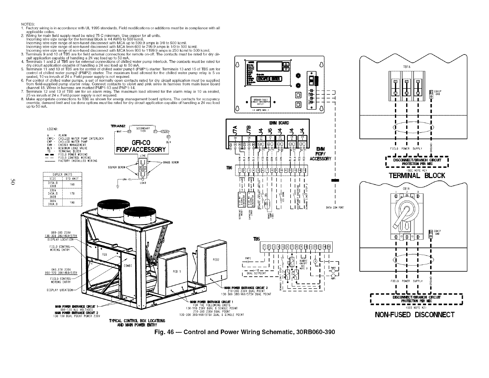
L//
0
NOTES:
1. Factory wiring is in accordance with UL 1995 standards. Field modifications or additions must be in compliance with all
applicable codes.
2. Wiring for main field supply must be rated 75 C minimum. Use copper for all units.
Incoming wire size range for the terminal block is #4 AWG to 500 kcml.
Incoming wire size range of non-fused disconnect with MCA up to 599.9 amps is 3/0 to 500 kcmiL
Incoming wire size range of non-fused disconnect with MCA from 600 to 799.9 amps is 1/0 to 509 kcmiL
Incoming wire size range of non-fused disconnect with MCA from 800 to 1199.9 amps is 250 kcmil to 500 kcml.
3. Terminals 9 and 10 of TB5 are for field external connections for remote on-orb The contacts must be rated for dry cir-
cuit application capable of handling a 24 vac load up to 50 mA.
4. Terminals 1 and 2 of TB5 are for external connections of chilled water pump interlock. The contacts must be rated tot
dry circuit application capable of handling a 24 vac load up to 50 mA.
5. Terminals 11 and 13 of TB5 are tor control of chilled water pump 1 (PMP 1) starter. Terminals 13 and 15 of TB5 are tor
control of chilled water pump2 (PMP2) starter. The maximum load allowed for the chilled water pump relay is 5 va
sealed, 10 va inrush at 24 v. Field power supply is not required.
6. For control of chilled water pumps, a set of normally open contacts rated for dry circuit application must be supplied
f_m tield-supplied pump starter relay. Connect contacts to violet and pink wires in harness from main base Lx)ard
channel 18. Wires in harness are marked PMPl-13 and PNPl-14.
7. Terminals 12 and 13 of TB5 are tor an alarm relay. The maximum load allowed for the alarm relay is 10 va sealed,
25 va inrush at 24 v. Field power supply is not required.
8. Make appropriate connections to TB6 as shown for energy management board options. The contacts for occupancy
override, demand limit and ice done options must be rated for dry circuit application capable of handling a 24 vac load
up to 50 mA.
LEGEND:
A - ALARM
CWPI- CHILLED WATER PIMP INTERLOC_
CWP -CHILLED WATER PUMP
EM_ - E_ERGT MANAGEMENT
HLV -MINIMUM LOAD VALVE
Tt - TERMINAL BLOCK
i i FIELD POWERW[R[RO
I I HELD COITROL WIRING
-- FACTORY I_DTALLZD WIRIRO
DUPLEX UMITD
SIRE S_D URIT
315A,D
330B
i 33RA i i
i3RSA,D i _70 i
i _RRB i i
_DRA I i
i 390A,D I 90 i
0 []
........... [] (
I
-7
i
I
I
I
I
_)ATA CO_ PORT
080-300 _3OV
]3O-DOO 380146RISTRV
DISPLAY LOCATION_
FIELD CONTROL
_IRING RRTRY_
060,070 230V
ORO-IRO 38R/_ROiD/SV
FIELD CONTROL _
WIRING E_TRY
RRO-IRD ALL VOLTAGES
M_N I_ B_E CI_ 2
ISO-190 DUAL POINT POWER 230V
RIO-30ORDOV DUAL POINT
IDO-SOR38014601575VDUAL POINT
FOR THE ROLLOW]RGUR[TS
130-I_0R30V DUAL _ SINGLEPOINT
_IO-DOODDDV DUAL POINT
13R-300310/460157RV_UAL_ SINGLEPOINT
TYPICAL CONTROLBOX LOCATIONS
AND MAI_ PO_R I_'RY
Fig. 46 -- Control and Power Wiring Schematic, 30RB060-390
TtilA
I I I I
I I I I
I I I I
I I I I
III
FIELD POWRR SUPPLY
liJ._..li. J[..
I_oll_n_l _e_ _I_ ii
(SEE_OTE_£]
TERMINAL BLOCK
CD]R
1 2 3
I I I I
III I
I I I I
III
FIELD)POWER SIPPL_"
I I I I
I" .... I. iI.. I...a ......
DISCQ_Mzc'r/BRANCH CIRCUII" I
IP_I_'ION Pt_ H_ j
<SEENOTE 121
NON-FUSED DISCONNECT

in. /1/4-18 NPT
REMOVAL
Fig. 47 -- Dual Leaving Water Thermistor Well
INSERT THERMISTOR UNTIL
O-RING MEETS THE
THERMISTOR WELL BODY.
WIRE TIE_
\\
LOOP
THERMISTOR WIRE
AND SECURE
TO CHILLED WATER PIPE
Fig. 48 -- Dual Leaving Water Thermistor
CARRIER COMFORT NETWORK COMMUNICATION
BUS WIRING --The communication bus wiring is a shielded,
3 conductor cable with &'ain wile and is field supplied and
installed in the field.
The system elements abe connected to the communication
bus in a daisy chain tuTangement. The positive pin of each
system element communication connector must be wired to the
positive pins of the system elements on either side of it. This is
also required for the negative and signal ground pins of
each system element. Wiring connections for CCN should be
made at TB (terminal block) 3. Consult the CCN Contractor's
Manual for further information. See Fig. 49.
NOTE: Conductors and drain wire must be 20 AWG
(American Wire Gage) minimum stranded, tinned coppel:
Individual conductors must be insulated with PVC, PVC/
nylon, vinyl, Teflon, or polyethylene. An aluminum/polyester
100% foil shield and an outer jacket of PVC, PVC/nylon,
chrome vinyl, or Teflon with a minimum operating tempera-
ture range of _4 F (-20 C) to 140 F (60 C) is required. Refer to
Table 13 for a list of manufacturers that produce CCN Bus
Wiring that meets these lequirements.
Table 13- CON Communication Bus Wiring
MANUFACTURER
Alpha
American
Belden
Columbia
Manhatten
Quabik
PART NUMBER
Regular Wiring Plenum Wiring
1895
A21451 A48301
8205 884421
D6451
M13402 M64430
6130
It is important when connecting to a CCN communication
bus that a color coding scheme be used for the entire network
to simplify the installation. It is recommended that red be used
for the signal positive, black for the signal negative, and white
for the signal ground. Use a similm scheme for cables contgfin-
ing different colored wiles. At each system element, the shields
of its communication bus cables must be tied togethel: If the
communication bus is entirely within one building, the result-
ing continuous shield must be connected to a ground at one
point only. If the communication bus cable exits from one
building and enters anothel: the shields must be connected to
grounds at the lightning suppressor in each building where the
cable enters or exits the building (one point per building only).
To connect the unit to the network:
1. Turn off power to the control box.
2. Cut the CCN wire and strip the ends of the red (+), white
(ground), and black (-) conductors. Substitute appropri-
ate colors for different colored cables.
3. Connect the red wile to (4-) terminal on TB3 of the plug,
the white wile to COM termimd, and the black wire to the
(-) terminal.
4. The RJI 4 CCN connector on TB3 can also be used, but is
only intended for temporary connection (for example, a
laptop computer running Service Tool).
IMPORTANT: A shorted CCN bus cable will prevent
some routines fiom running and may prevent the unit
fiom stalling. If abnormal conditions occur, disconnect
the machine fiom the CCN Network. If conditions
return to normal, check the CCN connector and cable.
Run new cable if necessary. A short in one section of
the bus can cause problems with all system elements
on the bus.
NON-CCN COMMUNICATION WIRING -- The 30RB units
offer severed non-CCN translators. Refer to the separate instal-
lation instructions for additiomd wMng steps.
51
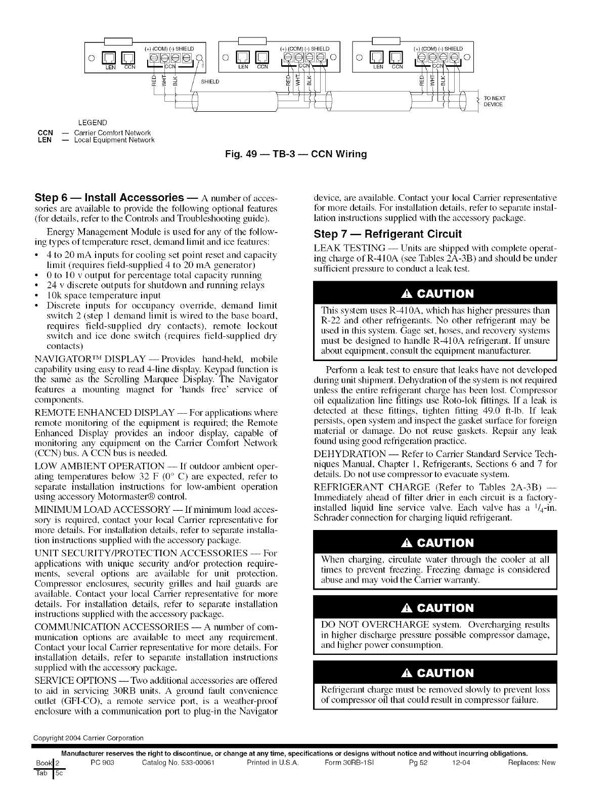
o12][]
LEN CCN
LEGEND
CCN -- Carrier Comfort Network
LEN -- Local Equipment Network
Fig. 49 -- TB-3 -- CCN Wiring
TO NEXT
DEVICE
Step 6 -- Install Accessories -- Anumber of acces-
sories are available to provide the following optional feaures
(for details, refer to the Controls and Troubleshooting guide).
Energy Management Module is used for any of the follow-
ing types of temperature reset, demand limit and ice features:
• 4 to 20 mA inputs for cooling set point reset and capacity
limit (requires field-supplied 4 to 20 mA generator)
• 0 to 10 v output for percentage total capacity running
• 24 v discrete outputs for shutdown and running relays
• 10k space temperature input
• Discrete inputs for occupancy override, demand limit
switch 2 (step 1 demand limit is wired to the base board,
requires field-supplied dry contacts), remote lockout
switch and ice done switch (requires field-supplied dry
contacts)
NAVIGATOR TM DISPLAY -- Provides hand-held, mobile
capability using easy to read 4-line display. Keypad function is
the same as the Scrolling Marquee Display. The Navigator
features a mounting magnet for 'hands free' service of
components.
REMOTE ENHANCED DISPLAY -- For applications where
remote monitoring of the equipment is required; the Remote
Enhanced Display provides an indoor display, capable of
monitoring any equipment on the Carrier Comfort Network
(CCN) bus. A CCN bus is needed.
LOW AMBIENT OPERATION -- If outdoor ambient oper-
ating temperatures below 32 F COo C) are expected, refer to
separate installation instructions for low-mnbient operation
using accessory Motorlnaster_) control.
MINIMUM LOAD ACCESSORY -- If minimum load acces-
sory is required, contact your local Canier representative for
more details. For installation details, refer to separate installa-
tion instructions supplied with the accessory package.
UNIT SECURITY/PROTECTION ACCESSORIES -- For
applications with unique security and/or protection require-
ments, several options are available for unit protection.
Compressor enclosures, security grilles and hail guards ae
available. Contact your local Carrier representative for more
details. For installation details, refer to separate installation
instructions supplied with the accessory package.
COMMUNICATION ACCESSORIES -- A number of com-
munication options are available to meet any requirement.
Contact your local Canier representative for more dettfils. For
installation details, refer to separate installation instructions
supplied with the accessory package.
SERVICE OPTIONS --Two additional accessories tue offered
to aid in servicing 30RB units. A ground fault convenience
outlet (GFI-CO), a remote service port, is a weather-proof
enclosure with a communication port to plug-in the Navigator
device, are available. Contact your local Carier representative
for mole details. For inst_dlation det_dls,refer to sepmate instal-
lation instructions supplied with the accessory package.
Step 7 -- Refrigerant Circuit
LEAK TESTING -- Units are shipped with complete operat-
ing charge of R-410A (see Tables 2A-3B) and should be under
sufficient pressure to conduct a leak test.
This system uses R-410A, which has higher pressures than
R-22 and other refiigemnts. No other refrigerant may be
used in this system. Gage set, hoses, and recovely systems
must be designed to handle R-410A refrigerant. If unsure
about equipment, consult the equipment manufacturec
Perfomt a leak test to ensure that leaks have not developed
during unit shipment. Dehydi'ation of the system is not required
unless the entire refrigerant charge has been lost. Compressor
oil equalization line fittings use Roto-lok fittings. If a let& is
detected at these fittings, tighten fitting 49.0 ft-lb. If leak
persists, open system and inspect the gasket surface for foreign
material or damage. Do not leuse gaskets. Repair any leak
found using good lefrigemtion practice.
DEHYDRATION -- Refer to Carrier Stan&ud Service Tech-
niques Manual, Chapter 1, Refrigerants, Sections 6 and 7 for
detgfils. Do not use compressor to evacuate system.
REFRIGERANT CHARGE (Refer to Tables 2A-3B) --
Immediately ahead of filter diier in each circuit is a factory-
installed liquid line service valve. Each valve has a l/4-in.
Schmder connection for charging liquid refrigerant.
When charging, circulate water through the cooler at all
times to prevent freezing. Freezing &image is considered
abuse and may void the Carrier waranty.
DO NOT OVERCHARGE system. Overcharging results
in higher discharge pressure possible compressor damage,
and higher power consumption.
Refrigerant charge must be removed slowly to prevent loss
of compressor oil that could result in compressor failure.
Copyright 2004 Carrier Corporation
Manufacturer reserves the right to discontinue, or change at any time, specifications or designs without notice and without incurring obligations.
PC 903 Catalog No. 533-00061 Printed in U.S.A. Form 30RB-1 SI Pg 52 12-04 Replaces: New
