CARRIER Furnace/Heater, Gas Manual L0503146
User Manual: CARRIER CARRIER Furnace/Heater, Gas Manual CARRIER Furnace/Heater, Gas Owner's Manual, CARRIER Furnace/Heater, Gas installation guides
Open the PDF directly: View PDF ![]() .
.
Page Count: 52
58NXA
DeMuxe 4-Way NuRipoise Fixed-Capacity
Direct Vent Condensing Gas Furnace
\isit _ v_w carrier.corn
tnstammation, Start-Up, and Operating
Sizes 040o140, Series 170
NEATUNG & COOUNG
A93040
NOTE: Read the entire instruction nmnua] before starting the
installation.
This symbol -->indicates a change since the tast issue,
TABLE OF CONTENTS
SAFETY CONSIDERATIONS 2
INTRODL CTION 4
CODES AND STANDARDS 4
ELECTROSTATI( DISCHARGE (ESD) PRECAUTIONS .... 5
APPLICATIONS ...................................... 6
General ............................................. 6
Lpflow Applications ............................... 6
Downflow Applications ............................. 8
Horizontal Lek (Supply-Air Discharge)
Applications ........................................ 10
Horizontal Right (Supply-Air Discharge)
Applications .................................... 11
LOCATION ......................................... ! 3
General ......................................... 13
Furnace Location Relative to Cooling
Equipment ...................................... ] 4
Hazardous Locations .............................. 14
INSTALLATION ........................................ 14
Leveling Legs (If"Desired) ............................ 14
Installation in Upfiow and Downflow
Applications ....................................... 15
Installation in Horizontal Applications .................. 16
Air Ducts ........................................ ] 7
General Requirements ............................ 17
Ductwork Acoustical Treatment ................... 17
Supply Ai* ( onnections ......................... 17
Return Air Connections .......................... 17
Filter Arrangement ................................ 1S
Bottom Closure Panel ............................ 19
Gas Piping ....................................... ] 9
Electrical Connections ............................ 20
115 v Wiring ................................. 20
24 v Wiring .................................. 22
Accessories ........................................................................ 22
Direct Venting ...................................... 22
Removal of Existing Furnaces t)om Common
Vent Systems .................................... 22
Combustion-Air and Vent Piping .................... 22
Vent Extension Pipe ............................ 27
Concentric Vent and Combustion-Air
Termination Kit Installation .............................................. 29
Multiventing and Vent Terminations .................. 33
Condensate Drain .................................. 34
General ....................................... 34
Application ....................................... 34
Condensation Drain Protection ..................... 35
START-UP, ADJL STMENTS AND SAFETY (HECK ........... 35
General ........................................... 35
Prime Condensate Trap With Water .................... 36
Purge Gas Lines ................................... 37
Sequence of Operation ............................. 37
Heating Mode ................................. 37
Cooling Mode ................................ 40
Thermidistat Mode ............................. 40
Continuous Blower Mode ........................ 41
Heat Pump Mode .............................. 41
Component Test ............................... 41
Adjustments ........................................ 42
Set Gas Input Rate ............................. 42
Set Temperature Rise ............................ 48
Adjust Blowe* Off Delay (Heat Mode) ................ 49
Set Thermostat Heat Anticipator .................... 49
(hock Safe w Controls ............................... 49
Check Primmy Limit Control ...................... 49
Check Pressure Switch .......................... 49
( hecklist .......................................... 50
Manufacturer reserves the right to discontinue, or change at any time, specifications or designs without notice and without incurring obligations.
PC 101 Catalog No. 535-80157 Printed in U.S.A. Form 58MXA-18SI Pg 1 2-05 Replaces: 58MXA-17SI
AIRFLOW
4>
_ HORIZONTAL ]
LEFT
AIRFLOW hAIRFLOW
©
AIRFLOW
A93041
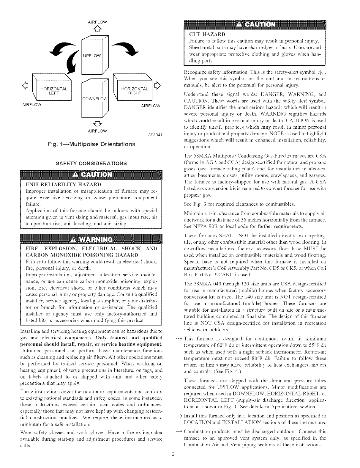
Fig. 1--MuRipoise Orientations
SAFETY CONSIDERATIONS
/NIT RELIABILITY HAZARD
Improper installation or misapplication of ihmace may re-
quire excessive servicing or cause premature component
failure
Application of this lhrnace should be indoors with special
attention given to vent sizing and material, gas input ratQ air
temperature rise, unit leveling, and unit sizing
FIRE, EXPLOSION, ELECTRICAL SHOCK AND
(ARBON MONOXIDE POISONING HAZARD
Failure to follow this warning could result in electrical shock,
fire_ personal ir!inry_ or death.
Improper installation, adjustment, alteration, service, mainteo
nance, or use can cause carbon monoxide poisoning, exploo
sion, fire, electrical shock, or other conditions which may
cause personal injury or property damage. Consuh a qualified
installer, service agency, local gas supplier, or your distribuo
tot or branch ibr information or assistance. The qualified
installer or agency must use only [hctoryoauthorized and
listed kits or accessories when modi_)ing this prodact.
Installing and servicing heating equipment can be hazardous due to
gas arid electrical components. Only trained and qualified
personnel s][muld install, repair, or service heating equipment.
Untrained personnel can perform basic maintenance f_anctions
such as cleaning and replacing air filters All other operations must
be performed by trained service personnel. When working on
heating equipment, observe precautions in literature, on tags, and
on labels attached to or shipped with unit and other safety
precautions that may apply
These instructions cover the minimmn requirements arid conform
to existing national standards and safety codes. In some instances,
these instructions exceed certain local codes and ordinances,
especially those that *nay not have kept up with changing resideno
tial construction practices. We require these instl-t,ctions as a
minimum fbr a saf_ installation.
Wear safety glasses and work gloves. Have a fire extinguisher
available during startoup and adjustment procedures and service
calls.
--€
-->
--€
(IT HAZARD
Failure to %11ow this caution *nay result in personal Jr!jury.
Sheet metal parts may have sharp edges or bun's Use care arid
wear appropriate protective clothing and gloves when hano
dling parts.
Recognize sa_kty infornlation. This is the safety-alert symbol Z_ "
When yon see this symbol on the unit and in instructions or
manuals, be alert to the potential ibr personal injury.
Understand these signal words: DANGER, WARNING, and
CAUTION. These words are used with the safctyoalert symbol.
DANGER identifies the most serious hazards which will result in
severe personal injm7 or death. WARNING signifies hazards
which could result in personal injury or death. CAUTION is used
to identii}" unsafe practices which may result in minor personal
injuw or product and property damage. NOTE is used to highlight
suggestions which will result in enhanced installation, reliability,
or operation.
The 58MXA Multipoise Condensing Gas-Fired Furnaces are CSA
(fbm_erly AGA and CGA) design-certified for natural and propane
gases (see fimaace rating plate) and _br installation in alcoves,
attics, basements, closets, utility rooms, crawlspaces, and garages.
The ihmace is factoryoshipped ibr use with natural gas. A CSA
listed gas conversion kit is required to convert Ihmace for use with
propane gas.
See Fig. 3 for required clearances to combustibles.
Maintain a l-in. clearance fi'om combustible materials to supply air
ductwork for a distance of 36 inches horizontally fiom the fhmace.
See NFPA 90B or local code ibr further requirements.
These ftunaces SHALL NOT be installed directly on carpeting,
tile, or any other combustible material other than wood flooring. In
downflow installations, factory accesso_' floor base MUST be
used when installed on combustible materials and wood flooring.
Special base is not required when this _iulaace is installed on
manufacturer's (?oil Assembly Part No. CD5 or CK5, or when (Toil
Box Part No. KCAKC is used.
The 58MXA 040 through 120 size units are (SA design-certified
for use in manufactured (mobile) homes when ihctory accessou
conversion kit is used The 140 size unit is NOT design-certified
for use in manufactured (mobile) homes. These thrnaces are
suitable for installation in a structure built on site or a manufac-
tured building completed at final site. The design of this thmace
line is NOT CSA design-certified for installation in recreation
vehicles or outdoors.
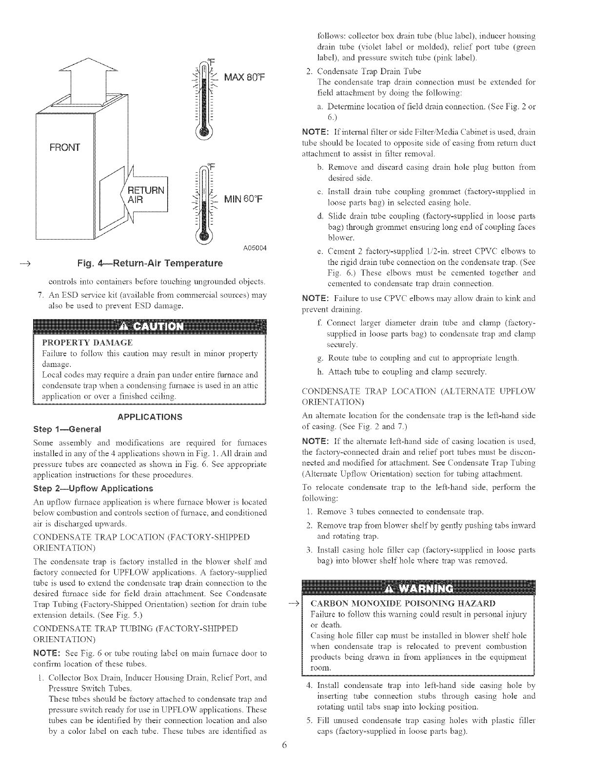
This fl*rnace is designed %r continuous return=air n_ininmm
temperature of 60_T db or intermittent operation down to 55°F db
such as when used with a night setback thermometer Return-air
temperature must not exceed 80°F db Failure to follow d_ese
remm air limits may affect reliability of heat exchangers, motors
and controls. (See Fig 4.)
These ihrnaces are shipped with the drain and pressure robes
connected for UPFLOW applications. Minor modifications are
required when used in DOWNFLOW, HORIZONTAL RIGHT, or
HORIZONTAL LEFT (supply=air discharge direction) applica-
tions as shown in Fig. 1. See details in Applications section.
Install this fku_ace only in a location and position as specified in
LO(ATION and INSTALLATION sections of these instructions.
Combustion products must be discharged outdoors. Connect this
fm'nace to an approved vent system only, as specified in the
(ombustion Air and Vent piping sections of these instructions
14 9'
TYP
26
26 £"
SIDE INLET
_ +_ .................. _
11"_ _ 23 :_"TYP
SIDE iNLET
26 %i6" TYP
CONDENSATE DRAIN
TRAP LOC,RHON
(DOWNFLOW &
HORIZONTAL LEFT)
_%-- /:-IN D{A
ACCESSORY
POWER ENTRY
CONDENSATE
DRAIN TRAP
LOCATION
(AJTERNATE
UPFLOW)
17 M_"
©
AIRFLOW
_A_
TLET
DRAIN LOC#<T_O N
(UPFLO_M)
30 /z"
FOR HORIZONTAL
HANGING
THERMOSTAT ENTRY
80 [10M iNLEt
39 %'
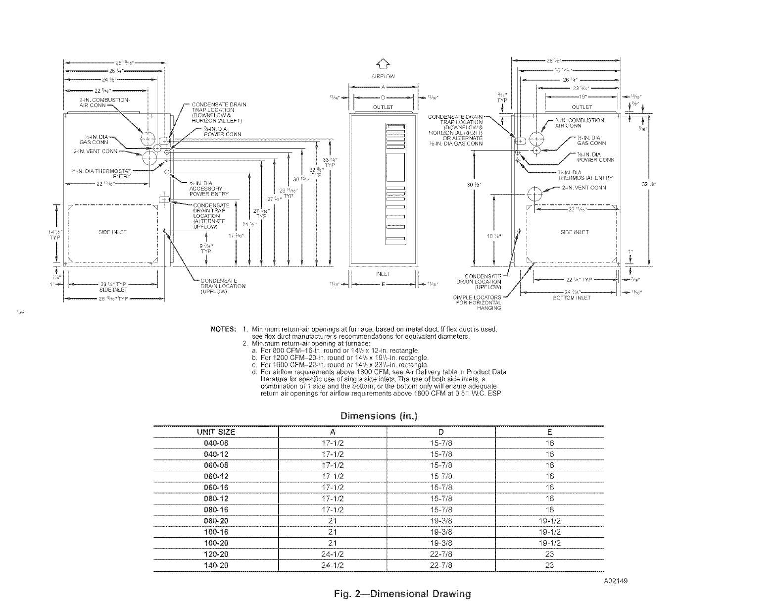
NOTES: 1. Minimum return-air openings at furnace, based on metal duct, F flex duct is used,
see flex duct manufacturers recommendations for equivalent diameters
2 Minimum return-air opening at furnace:
a For 800 CFM-16qn round or t4/: x 124n, rectangle
b, For 1200 CFM-20qn, round or 14/, x 19/:din rectangle,
c, For 1600 CFM-224n, round or 14/: x 23/Mm rectangle
d For airflow requirements above 1800 CFM, see Air Delivery table in Product Data
literature for specific use of single side inlets, Tbe use of both side inlets, a
combination of 1 side and the bottom, or the bottom only will ensure adequate
return air openings for airflow requirements above 1800 CFM at 05 WC ESP
UNIT S_ZE
040-08
040-12
080-08
060-12
060-10
080-12
080-16
080-20
100-16
100-20
120-20
140-20
Dimensions (in.)
A
17-I/2
17-I/2
17-I/2
17-1/2
17-1/2
17-1/2
17-1/2
21
21
21
24-1/2
24-1/2
D
15-7/8
15-7/8
15-7/8
15-7/8
15-7/8
15-7/8
15-7/8
19-3/8
19-3/8
19-3/8
22-7/8
22-7/8
E
16
16
16
16
16
16
16
19-1/2
19-1/2
19-1/2
23
23
A02149
Fig. 2--Dimensional Drawing
--> Never test %r gas leaks with an open flame. [se a commercially
available soap solution made specifically fbr detection of leaks to
check all connections as specified in the GAS PIPING section of
these instructions
--> Always install the Nmace to operate within the t_omace's intended
rise range with a duct system which has an external static pressure
within the allowable range as specified in the SET TEMPERA=
TURE RISE section of these instructions.
--> When a fi/rnace is installed so that supply ducts carry air circulated
by the Nmace to areas outside the space containing the furnace,
the return air shall also be handled by ducts sealed to the Nrnace
casing and tem?inating outside the space containing the Nrnace.
--> A gas-fired Nrnace for installation in a residential garage must be
installed as specified in the Hazardous Locations section of these
insm_ctions,
---> The t:urnace is not to be used for tempma W heating of buildings o1"
strt/ctures under construction unless the furnace installation and
operation complies with the first (AUTION in the LO(ATION
section of these instructions.
This thmace must be installed with a direct-vent (combustion air
and flue gas) system and a factory accessory tei_nination kit. In a
direct-vent system, all air for combustion is taken directly from the
outdoor atmosphere and flue gases are discharged to the outside
atmosphere. See Nmace and factory accesso_ vent-air intake
termination kit instructions for proper installation.
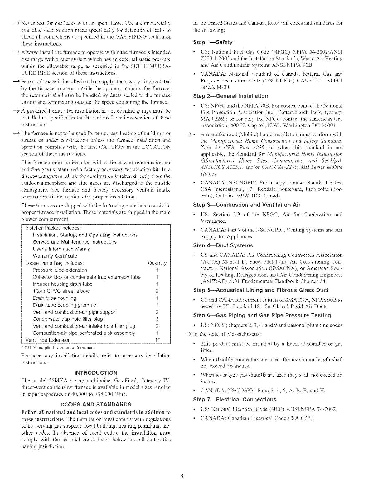
These fimaaces are shipped with the following materials to assist in
proper furnace installation. These materials are shipped in the main
blower compartment.
Installer Packet includes:
Installation, Startup, and Operating instructions
Service and Maintenance instructions
User's Information Manual
Warranty Certificate
Loose Parts Bag includes: Quantity
Pressure tube extension 1
Collector Box or condensate trap extension tube 1
inducer housing drain tube 1
l/2qn CPVC street elbow 2
Drain tube coupling 1
Drain tube coupling grommet 1
Vent and combustion-air pipe support 2
Condensate trap hole filler plug 3
Vent and combustion-air intake hole filler plug 2
Combustion-air pipe perforated disk assembly 1
Vent Pipe Extension 1"
ONLY supplied with some furnaces.
For accessory installation details, refer to accessory installation
instl_._ctions.
_NTRODUCTmON
The model 58MXA 4=way multipoise, Gas=Fired, Category IV,
direct-vent condensing fitrnace is available in model sizes ranging
in input capacities of 40,000 to 138,000 Bmh
CODES AND STANDARDS
FMIow all nationM and locM codes and standards in addition to
these instructions° The installation must comply with regulations
of the serving gas supplier, local building, heating, plurnhing, and
other codes. In absence of local codes, the installation must
comply with die national codes listed below and all authorities
having jurisdiction.
In the United States and Canada, %llow all codes and standards %r
the fbllowing:
Step l--Safety
• US: National Fuel Gas (7ode (NFGC) NFPA 54-2002/ANSI
Z223.1-2002 and the Installation Standards, Warm Air Heating
and Air Conditioning Systems ANSI NFPA 90B
• (ANADA: National Standard of Canada, Natural Gas and
Propane Installation (ode (NSCNGPIC) CANiCGA -B149,1
=and2 M=00
Step 2--General Installation
• US: NFGC and the NFPA 90B. For copies, contact the National
Fire Protection Association Inc, Battewmarch Park, Quincy,
MA 02269; or for only the NFG( contact the American Gas
Association, 400 N. (apitol, N.W., Washington DC 20001
--> * A manufhctured (Mobile) home installation must confbrm with
the Manzt_bctured _12)me Construction and 5"qfi._0' Standard,
Tide 24 (_FR, Part 3280, or when this standard is not
applicable, the Standard fbr :l,Ian@mtzcred Home in.stgd/ation
(._Iclmt/actHred D))me Sites, ('omm_¢nitie.s, and Set-L_.s),
A_ifZ,.VCS' A225. I, an_or (it_\-_ (WA-Z240, MN Serie,s Mofile
• (ANADA: NSCNGPI(L For a copy_ contact Standard Sales,
CSA International, 178 Rexdale Boulevard, Etobicoke (Tot=
onto), Ontario, MPW 1R3, Canada.
Step a--Combustion and Ventilation Air
• US: Section 53 of the NFG(, Air for (ombnstion and
Ventilation
• CANADA: Part 7 of the NSCNGPIC, Venting Systems and Air
Supply for Appliances
Step 4--Duct Systems
• US and CANADA: Air (onditioning (ontractors Association
(ACCA) Manual D, Sheet Metal and Ai* Conditioning Con=
tractors National Association (SMACNA), or American Soci-
ety of Heating, Refrigeration, and Air Conditioning Engineers
(ASHRAE) 200I Fundamentals Handbook Chapter 34
Step g--Acoustical Lining and Fibrous Glass Duct
• Ers and CANADA: cmTent edition of' SMACNA, NFPA 90B as
tested by EL Standard 18! for Class I Rigid Air Ducts
Step g--Gas Piping and Gas Pipe Pressure Testing
• US: NFGC chapters 2, 3, 4_ and 9 and national plumbing codes
--> In the state of Massachusetts:
* This product must be installed by a licensed plun_her or gas
fitter
* When flexible connectors are used, the maximum length shall
not exceed 36 inches
* When lever type gas shutoff?4 are used they shall not exceed 36
inches
*CANADA: NSCNGPI( Parts 3, 4, 5, A, B, E, and H.
Step 7--Electrical Connections
* US: National Electrical Code (NEC) ANSIiNFPA 70=2002
* (ANADA: Canadian Electrical Code CSA (22 1
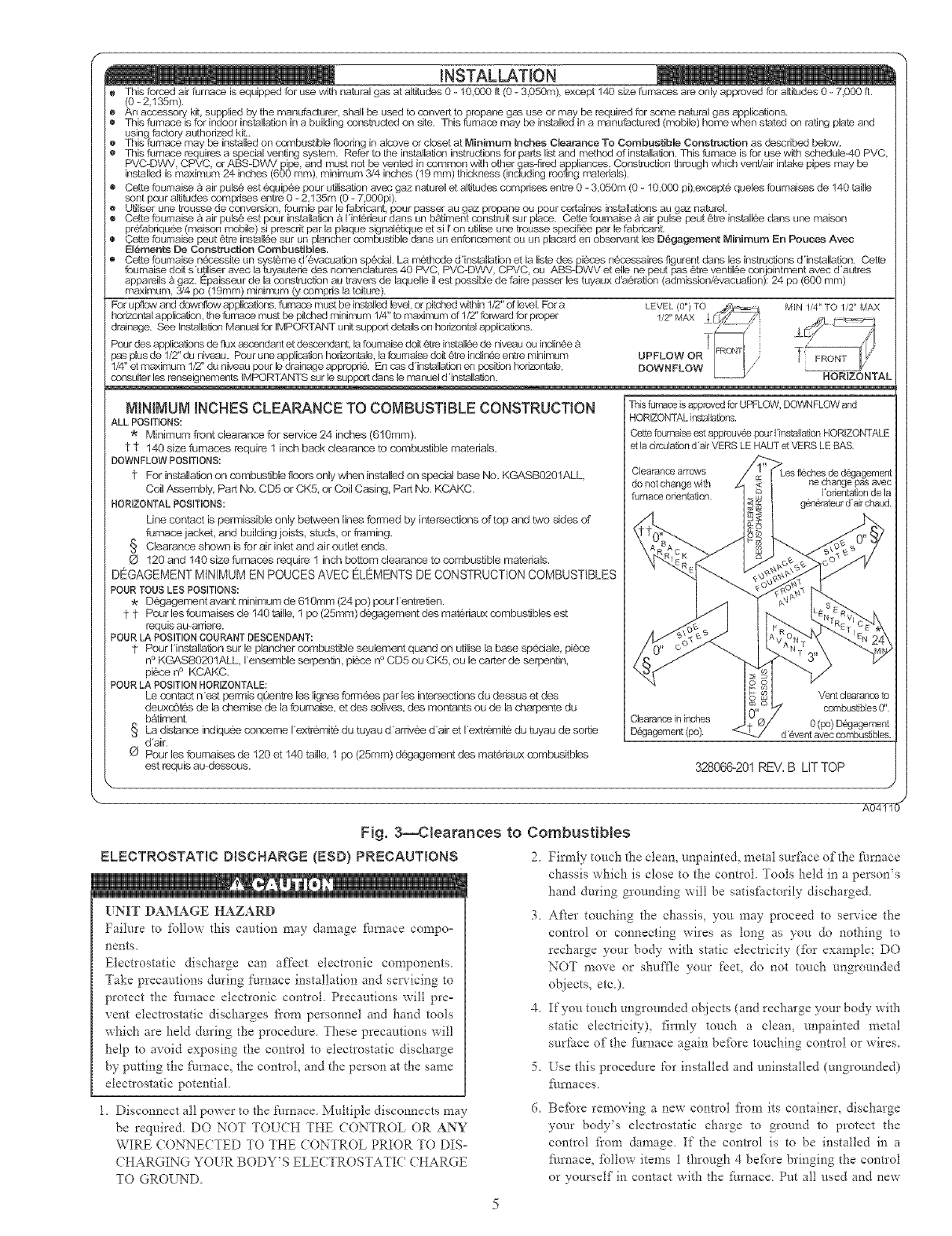
This forced air furnace is equipped for use with natural gas at altitudes 0 -10,000 ft (0 -3,050m), except 14,0 size furnaces are only approved for altitudes 0 -7,000 ft.
(0 -2 135m).
An accessory kit supplied by the manufacturer, shall be used to convert to propane gas use or may be required for some natural gas applications.
This furnace is for indoor installation in a building cy,_nstructed on site. This furnace may be installed in a manufactured (mobile) home when stated on rating plate and
using factory authorized kit..
This furnace may be installed on combustible floedng in alcove or closet at Minimum inches Clearance To Combustible Construction as described below.
This fumace requires a special venting system. Refer to the installation instructions for parts list and method of installation. This fumace is for use with schedula40 PVC,
PVC-DWV CPVC or ABS-DWV pipe and must not be vented in common with other gas-fired appliances. Construction through whiclq vent/air intake pipes may be
installed is maximum 24 inches (600 nlm), minimum 3/4 inches (19 mm) thickness (including roofing n_qteriala).
Cette foumaise _ air pula_ est d,quip_e pour utillaation avec gaz naturel et altitudes comprises entre 0 -3,050m (0 -10,000 pi),except6 queles fournaises de 140 taille
sont pour altitudes comprises entre 0 - 2,135m (0 - 7,000pi).
Utiliser une trausse de conversion fournie par le fabricant, pour passer au gaz propane ou pour certaines installations au gaz natarel.
Cette foumaise A air pula6 est pour installation & Hnt6rlaur dans un bAtiment construit sur place. Cette foumalae & air pulse paut 6tre installd, e dens une maison
pr6fabriqu6e (malaon mobile) si prescrit par la plaque signal6tique et si I_on utilise une trousse speclfi6e par la fabrlaant.
Cette foumaise peut 6tre installd, e sur un plancher combustible dens un enfoncement ou un placard en observant les D_gagement Minimum En Pouces Avec
Elements De Construction Combustibles.
Cette fournalae n@cessite un systeme d'6vacuation sp6cial. La n_thede d'installation et la Ilata des pieces nd,cessaires flgurent dens les instructions d'installation. Cette
fournaise doit s'utiliser avec la tayautede des nomenclatures 40 PVC, PVC-DWV, CPVC ou ABS-DWV et ella ne peut pas 6tre ventil_e conjolatment avec d'autres
appareila & gaz. Epaisseur de la construction au travers de laquelle il est possible de faire passer les tuyaux d'a6ration (admlaslan/6vacuation); 24 po (600 mm)
maximum, 3/4 po (19mm) minimum (y compris la toiture).
For upflc_w and cDwnflow applications, furnace must be installed level, or pitched within 1/2" of level. For a M IN 1/4" TO 1/2" MAX
horizontal application, the furnace must be pitahed minimum 1/4" to maximum of 1/Z' forward for propar
drainage. See Installation Manual for IMPORTANT unit support details on horizontal applications.
Pour des applications de flux ascendant et descendant, la fournalae doit (}tre installg_e de niveau ou laclla6e _ T
pas plas de 1/Z' du niveau. Pour une application hodzontale, la fournaise deit (}tre inclin6e entra n-tinimum UPFLOW OR
1/4" et maximum 1/2" du niveau pour le drainage approprid,. En cas d'installatlan en position horizontak_, DOWNFLOW
consulter les renseignementa JMPORTANTS sur le support dens le manuel d'ind_allation. HORIZONTAL
NININUN INCHES CLEARANCE TO COMBUSTIBLE CONSTRUCTION
ALL POSITIONS:
Minimum front clearance for sep,zice 24 inches (610ram).
1 1" 140 size furnaces require 1 inch back clearance to combustible materials.
DOWNFLOW POSITIONS:
1" For installa/Jon on cornbustible floors only when installed on special base No. KGASB0201ALL
Coil Assembly, Part No. CD5 or CKS, or Coil Casing, Part No. KCAKC.
HORIZONTAL POSITIONS:
Line contact is permissible only between lines formed by intersections of top and two sides of
furnace jacket, and building joists, studs, or framing.
§ Clearance shown is for air inlet and air outlet ends.
O 120 and 140 size furnaces require 1 inch bottom clearance to combustible materials.
DEGAGEMENT MINIMUM EN POUCES AVEC ELEMENTS DE CONSTRUCTION COMBUSTIBLES
POUR TOtJS LES POSITIONS:
Degagement avant minimum de 610mm (24 po) pour I'entrelien.
1" 1" Pourles foumaises de 140taille, 1 po(25mm)degagement des mat6riaux combustiblesest
requis au_arriere.
POUR LA POSITION COURANT DESCENDANT:
1" Pour Hnstallalion sur le plancher combustible seulement quand on utilise la base spedale, piece
n ° KGASB0201ALL I'ensernble serpaniin, pi6ce n° CD5 ou CKS, ou le carter de serpentin,
piece n ° KCAKC.
POUR LA POSITION HORIZONTALE:
Le contact n'est permis qOen_-e les lignes formees par les intersectioes du dessus et des
deuxc6tgs de la d:_emise de la foumaise, et des solives, des montanta ou de la d:rarpente du
batirnent
§ La distance indiquee concerne I'extr@mite du tuyau d'arfivee d'air et I'extrernit6 du tuyau de sortie
d'air.
O Pour les fournaises de 120 et 140 taille, 1 po (25mm) degagement des materiaux combusitbles
est requis au dessous.
This furnace is approved for UPFLOW, DOW_q FLOW and
HORIZONTAL ins'talla_ns.
Cette fournaise est approuv@e paur Hns[allation HORIZONTALE
et la drculatlan d'air VERS LE HAUT et VERS LE BAS.
Cl_aranoa at-raws
do not change with ne cl]ange pas avec
furnace orlantation, I'otientation de la
g6n6rateur d'ak chaud.
Vent clearance to
combustibles 0".
Clearance in inches 0 (1::o)Dg%Jagement
D_gagement (po). d'@vent avec combustibles.
328066-201 REV. B LIT TOP
Fig. 3--Clearances to Combustibles
ELECTROSTAT{C DISCHARGE {ESD} PRECAUT{ONS 2 Firmly [ouch the clean, unpaiute& metal surface of the _.m_ace
UNIT DAMAGE HAZARD
Failure to follow this caution may damage furnace compo=
nents,
Electrostatic discharge can affect electronic components
Take precautions during [_urnace installation and servicing to
protect the f_m_ace electronic control. Precautions will pre=
vent electrostatic discharges fi'om personnel and hand tools
which are held during the procedure. These precautions will
help to avoid exposing the control to electrostatic discharge
by putting the furnace, the control, and the person at the same
electrostatic potential.
l, Disconuect all power to the [_urnace Multiple disconnects may
be required DO NOT TOUCH THE CONTROL OR ANY
WIRE CONNECTED TO THE CONTROL PRIOR TO DIS=
CHARGING YOUR BODY' S ELE(TROSTATIC ( HARGE
TO GROUND
4_
5_
d.
chassis which is close to the control Tools held in a person's
haud during grounding will be satisfactorily discharged.
After touching the chassis, you may proceed to service the
control or connecting wires as tong as you do nothing to
recharge your body with static electricity (for example; DO
NOT move or shuffle your feet, do not touch ungrouuded
objects, etc)
If you touch uugrounded ohjects (and recharge your body with
static electricity), firmly touch a clean, uupainted metal
surface of the f_,_mace again befbre touching control or wires.
Use this procedure for installed and uninstalled (ungrounded)
_/fnaces
Betbre removing a new control flora its container, discharge
your body's electrostatic charge to grouud to protect d'*e
control f?om damage If [!_e control is to be installed iu a
f_,u_ace, follow items 1 through 4 bef_._re bringing the control
or yourself in contact with the furnace Put all used and new
FRONT
MAX 80°F
M[N 60°F
-->
A05004
Fig, 4_Retum-Air Temperature
controls into containers be%re touching ungrounded objects
7. An ESD service kit (available fiom commercial sources) may
also be used to prevent ESD damage.
PROPERTY DAMAGE
Failure to follow this caution may result in minor property
damage.
Local codes may require a drain pan under entire filmace and
condensate trap when a condensing furnace is used in an attic
application or over a finished ceiling.
APPLICATIONS
Step l--General
Some assembly and modifications are required %r furnaces
installed in any of the 4 applications shown in Fig. 1. All &ain and
pressure robes are connected as shown in Fig 6 See appropriate
application instla/ctions fbr d-lese procedures
Step 2--Upf[ow Applications
An upflow furnace application is where t_mnace blowei is located
below combustion and controls section of f_./rnace, and conditioned
air is discharged upwards.
CONDENSATE TRAP LOCATION (FACTORY-SHIPPED
ORIENTATION)
The condensate tlap is flactol-y installed in the blower shelf and
fhctory connected for UPFLOW applications A factoo-supplied
tube is used to extend the condensate trap drain connection to the
desired t'urnace side for field drain attachment. See (ondensate
Trap Tubing (Factory=Shipped Orientation) section fbr drain tube
extension details. (See Fig. 5.)
CONDENSATE TRAP TUBING (FACTORY-SHIPPED
ORIENTATION)
NOTE: See Fig. 6 or robe routing label on main fi/mace door to
confirm location of these tubes.
1. Collector Box Drain, Inducer Housing Drain, Relief Port, and
Pressure Switch Tubes.
These robes should be factory attached to condensate trap and
pressure switch ready for use in UPFLOW applications. These
robes can be identified by their connection location and also
by a color label on each robe. These robes are identified as
-->
%llows: collector box &ain robe (blue label), inducer hmMng
&ain robe (violet label or molded), relief port robe (green
label), and pressure switch robe (pink label)
2, Condensate Trap Drain Tube
The condensate trap drain connection must be extended for
field attachment by doing the fbllowing:
a. Detem_ine location of field drain connection. (See Fig. 2or
6.)
NOTE: If internal filter or side Filter/Media (abinet is used, &ain
robe should be located to opposite side of casing fiom return duct
attachment to assist in filter removal.
b. Remove and discard casing drain hole plug button Ii"om
desired side.
c. Install &ain robe coupling grommet (factow-supplied in
loose parts bag) in selected casing hole.
d. Slide &ain robe coupling (fbctory=supplied in loose parts
bag) through grommet ensuring tong end of coupling fitces
blower.
e. Cement 2 factory=supplied 1/2-in. street CPVC elbows to
the rigid drain tube connection on the condensate trap. (See
Fig. 5.) These elbows must be cemented together and
cemented to condensate trap drain connection
NOTE: Failure to use CPV( elbows may allow &ain to kink and
prevent draining.
£ Connect larger diameter drain tube and clamp (factory-
supplied in loose parts bag) to condensate trap and clamp
securely.
g. Route robe to coupling and cut to appropriate length.
h. Attach robe to coupling and clamp securely.
CONDENSATE TRAP LO(ATION (ALTERNATE LPFLOW
ORIENTATION)
An alternate tocation fbr d-le condensate t_ap is the left=hand side
of casing. (See Fig 2 and 7)
NOTE: If the alternate left°hand side of casing location is used.
the fimtolT°connected &ain and relief port tubes must be discon-
nected and modified for attachment. See Condensate Trap Tubing
(Alternate Upflow Orientation) section for tubing attachment.
To relocate condensate tlap to the left-hand side, perfbm_ the
following:
1. Remove 3 tubes connected to condensate trap.
2. Remove trap ti"om blower shelf by gently pushing tabs inward
and rotating trap.
3. Install casing hole filler cap (factory=supplied in loose parts
bag) into blower shelf hole where trap was removed.
N
CARBON MONOXIDE POISONING HAZARD
Failure to £dlow this warning could result in personal inju W
or death.
Casing hole filler cap must be installed in blower shelf hole
when condensate trap is relocated to prevent combustion
products being drawn in ti'om appliances in the equipment
1"OO111.
4. Install condensate trap into teftohand side casing hole by
inserting robe connection stubs through casing hole and
rotating until tabs snap into locking position.
5. Fill unused condensate trap casing holes with plastic filler
caps (fi_ctory=supplied in loose parts bag)
r--- BLOWER SHELF _ FURNACE
/X DOOR /_ CONDENSATE
Jf r-- CONDENSATE \/TRAP
/ / TRAP (INSIDE) X/FURNACE
X]s'w
FIELD2 '4 1 '2
/_ \ DRAIN
X---ALTERNATE DRAIN \ CONN
TUBE LOCATION \
CONDENSATE TRAP _ SIDE VIEW FRONT VIEW
DRAIN TUBE LOCATION DOWNFLOW AND ALTERNATE
UPFLOW APPLICATIONS EXTERNAL UPFLOW APPLICATIONS
FURNACE
OOR ! FURNACE
IDE
DRAIN
CONN
END VIEW FRONT VIEW
HORIZONTAL
APPLICATIONS
7
(OPTIONAL) /
._111/2 /
GUIDES
(WHEN USED)
FRONT VIEW
71/8
7/8Z :
SIDE VIEW
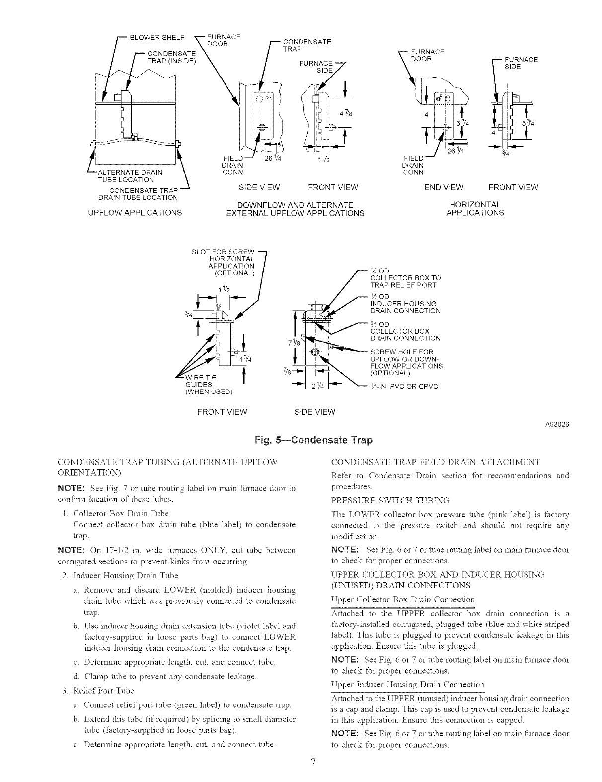
Fig. 5--Condensate Trap
/40D
COLLECTOR BOX TO
TRAP RELIEF PORT
%OD
INDUCER HOUSING
DRAIN CONNECTION
/80D
COLLECTOR BOX
DRAIN CONNECTION
SCREW HOLE FOR
UPFLOW OR DOWN-
FLOW APPLICATIONS
(OPTIONAL)
V2-1N PVC OR CPVC
CONDENSATE TRAP TUBING (ALTERNATE UPFLOW
ORIENTATION)
NOTE: See Fig 7 or robe routing label on nmin I_urnace door to
confim_ location of these tubes
1, (ollector Box Drain Tube
(onnect collector box &ain robe (blue label) to condensate
trap,
NOTE: On 17=1/2 in wide k'urnaces ONLY, cut tube between
corrugated sections to prevent kinks from occurring,
2, Inducer Housing Drain Tube
a, Remove and discard LOWER (molded) inducer housing
drain tube which was previously connected to condensate
trap,
b, Use inducer housing &ain extension tube (violet label and
factory-supplied in loose parts bag) to connect LOWER
inducer housing drain connection to the condensate trap,
c Detem_ine appropriate length, cut, and connect robe,
d, (lamp robe to prevent any condensate leakage,
3, Relief Port Tube
a (onnect relief port tube (green label) to condensate trap,
b, Extend this robe (if required) by splicing to snmll diameter
robe (factory=supplied in loose parts bag),
c Detem_ine appropriate length, cut, and connect robe,
A93026
CONDENSATE TRAP FIELD DRAIN ATTACHMENT
Refer to Condensate Drain section for recommendations and
procedures,
PRESSURE SWITCH TL BING
The LOWER collector box pressure robe (pink label) is facto U
connected to the pressure switch and should not require any
modification,
NOTE: See Fig. 6 or 7 or robe routing label on main Nrnace door
to check for proper connections,
UPPER (OLLECTOR BOX AND INDU(ER HOUSING
(L NUSED) DRAIN CONNECTIONS
Erpper Collector Box Drain Connection
Attached to the UPPER collector box drain connection is a
factow-installed corrugated, plugged tube (blue and white striped
1abel), This tube is plugged to prevent condensate teakage in this
application Ensure this robe is plugged,
NOTE: See Fig 6 or 7 or robe routing label on nmin f_ulmce door
to check for proper connections
Upper Inducer Housing Drain Connection
Attached to the [?PPER (unused) inducer housing &ain connection
is a cap and clamp, This cap is used to prevent condensate leakage
in this application, Ensure this connection is capped,
NOTE: See Fig, 6 or 7 or robe routing label on nmin fi/rnace door
to check for proper connections,
PLUG
COLLECTOR
DRAIN TUBE (BLUE
& WHITE STRIPED)
COLLECTOR
TUBE (PINK)
COLLECTOR BOX "-_
TUBE (GREEN)
INDUCER
(MOLDED) DRAIN
TUBE (BEHIND
COLLECTOR BOX
DRAIN TUBE)
DRAIN TUBE (BLUE)
FACTORY-SUPPLIED
DRAIN TUBE
COUPLING (LEFT
DRAIN OPTION)
PLUG
CAP
COLLECTOR BOX
DRAIN TUBE (BLUE
& WHITE STRIPED)
COLLECTOR BOX
TUBE (PINK)
COLLECTOR BOX --
TUBE (GREEN)
COLLECTOR BOX --
DRAIN TUBE (BLUE)
CONDENSATE _
TRAP EL
INDUCER J
HOUSING
DRAIN TUBE
(VIOLET)
©
O O
FIELD-INSTALLED
FACTORY-SUPPLIED
DRAIN TUBE
FIELD-INSTALLED
FACTORY-SUPPLIED
_i2-1N CPVC STREET
ELBOWS (2) FOR
LEFT DRAIN OPTION
FIELD-INSTALLED
FACTORY-SUPPLIED
DRAIN TUBE
COUPLING (RIGHT
DRAIN OPTION)
A94163
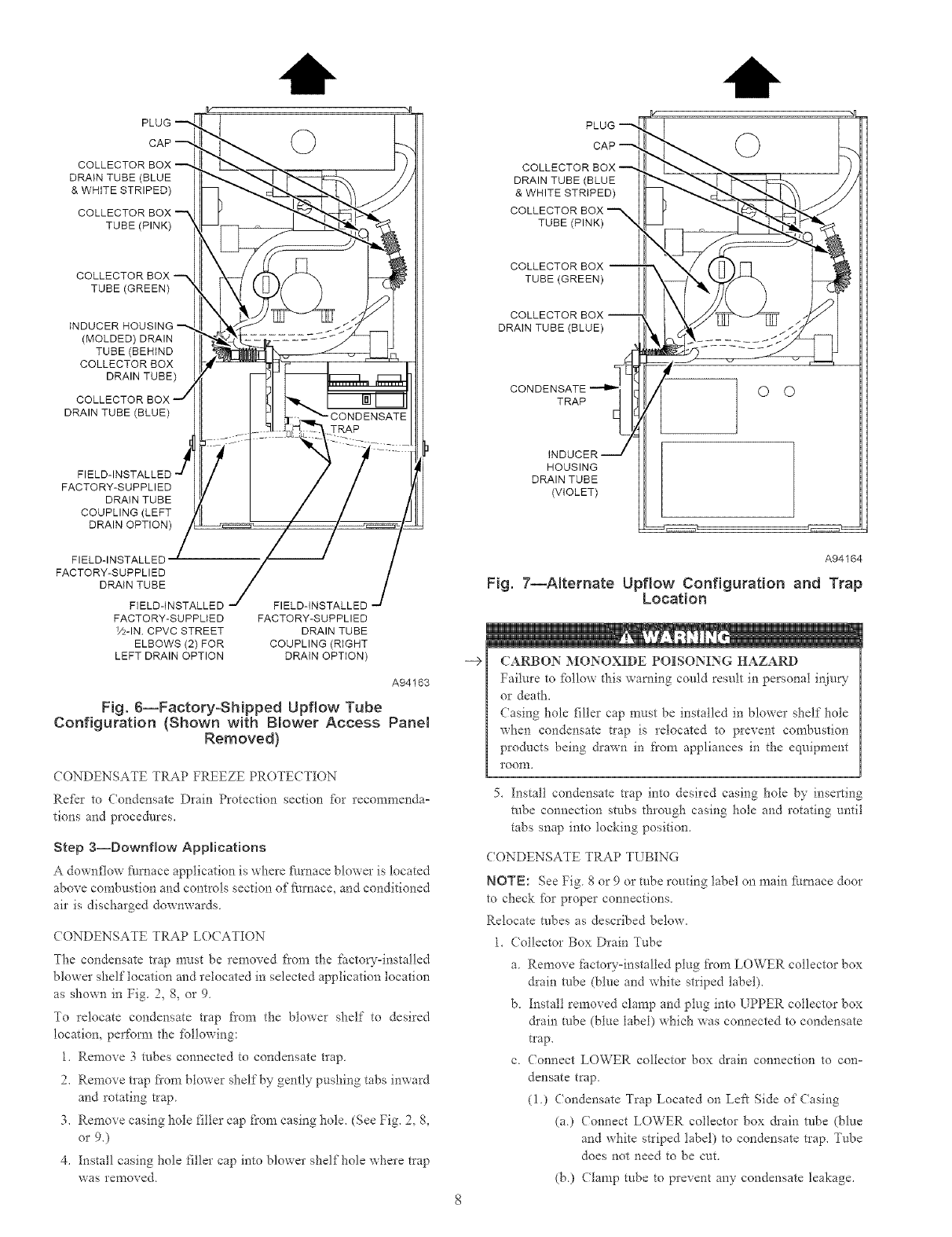
Fig. 6--Factory-Shipped Upflow Tube
Configuration (Shown w{th BNower Access Panel
Removed}
CONDENSATE TRAP FREEZE PROTECTION
Ref?r to Condensate Drain Protection section %r recommenda°
lions and procedures.
Step 3--Downfiow Applications
A downflow _/mace application is where :_trnace blower is located
above congbustion and controls section of fi_rnace, and conditioned
air is discharged downwards
( ONDENSATE TRAP LO(ATION
The condensate tlap mttst be removed from the factow-installed
blower shelf location and relocated in selected application location
as shown in Fig. 2, 8, or 9
To relocate condensate trap from the blower shelf to desired
location, perform the following:
1. Remove 3 robes connected to condensate trap
2. Remove tlap fiom blower shelf by gently pushing tabs inward
and rotating trap
3. Remove casing hole filler cap from casing hole. (See Fig. 2, 8,
or 9.)
4. [nstall casing hole filler cap into blower shelf hole where trap
was removed
-->
A94164
Fig. 7--ARernate Upflow Configuration and Trap
Location
CARBON MONOXIDE POISONING HAZARD
Failm'e to follow this warning could result in personal inju W
or death,
Casing hole filler cap must be installed in blower shelf hole
when condensate trap is relocated to prevent combustion
products being drawn in from appliances in the equipment
roonl.
5. [nstall condensate trap into desired casing hole by inserting
robe connection stubs through casing hole and rotating until
tabs snap into locking position,
CONDENSATE TRAP TUBING
NOTE: See Fig 8 or 9 or tube routing label on main f:umace door
to check for proper connections,
Relocate robes as described below,
1. Collector Box Drain Tube
a. Remove factory=installed plug from LOWER collector box
drain robe (blue and white striped label),
b. Install removed clamp and plug into UPPER collector box
&ain robe (blue label) which was connected to condensate
t_ap.
c (onnect LOWER collector box drain connection to con=
densate trap.
(i) (ondensate Trap Located on Left Side of (asing
(a) (onnect LOWER collector box &ain robe (blue
and white striped 1abel) to condensate trap. Tube
does not need to be cut.
(b) Clamp tube to prevent any condensate leakage.
COLLECTOR BOX -'_
DRAIN TUBE (BLUE)
TUBE (GREEN)
EXTENSION TUBE
COLLECTOR BOX
TUBE (PINK)
DRAIN TUBE (BLUE
& WHITE STRIPED)
COLLECTOR BOX
EXTENSION TUBE
TRAP ©
iNDUCER HOUSING
DRAIN TUBE (VIOLET) /
A94165
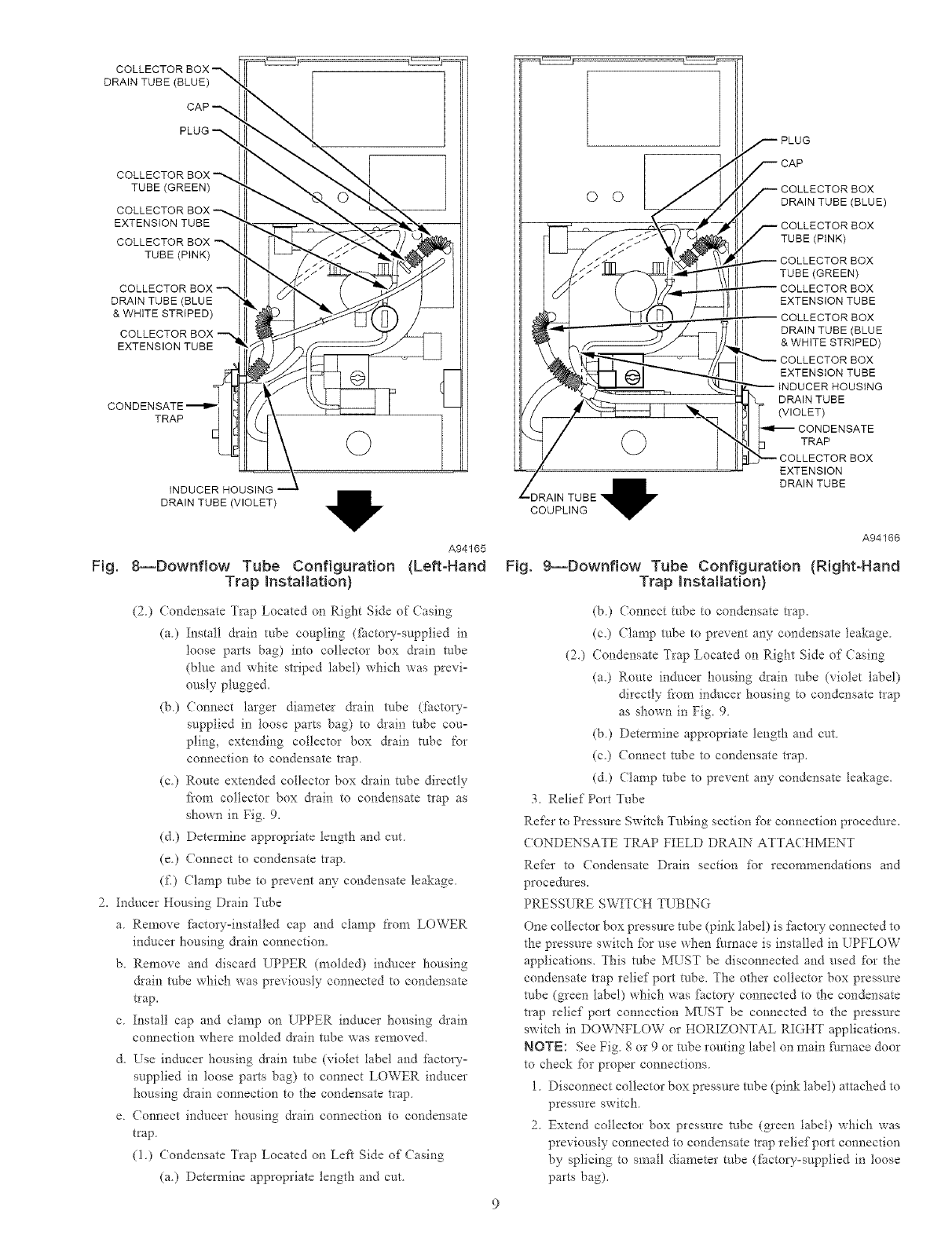
Fig. 8--Downflow Tube Configuration (Left-Hand
Trap Instatlat{on)
(2) Condensate Trap Located on Right Side of (asing
(a) Install drain tube coupling d5ctow-supplied in
loose parts bag) into collector box drain robe
(blue and white striped label) which was previo
ously plugged.
(b) Connect larger diameter &ain robe (gmtoryo
supplied in loose parts bag) to &ain tube couo
piing, extending collector box drain robe for
connection to condensate trap
(c.) Route extended collector box &ain tube directly
from collector box &ain to condensate trap as
shown in Fig. 9.
(d) Determine appropriate length and cut
(e) (onnect to condensate trap
(f.) Clamp robe to prevent any condensate leakage.
2. Inducer Housing Drain Tube
a. Remove fi_ctoL-y-installed cap and clamp from LOWER
inducer housing drain connection.
b. Remove and discard UPPER (molded) inducer housing
&ain robe which was previously connected to condensate
t_ap,
c Install cap and clamp on UPPER inducer housing &ain
connection where molded &ain robe was removed.
d. Use inducer housing &ain robe (violet label and factory°
supplied in loose parts bag) to connect LOWER inducer
housing &ain connection to the condensate trap.
e. Connect inducer housing drain connection to condensate
trap.
(1.) Condensate Trap Located on Left Side of Casing
(a.) Detemline appropriate length and cut.
O O
©
,DRAIN TUBE _1_
COUPLING
Fig.
_PLUG
_CAP
_---COLLECTOR BOX
DRAIN TUBE(BLUE)
_ COLLECTOR BOX
TUBE (PINK)
COLLECTOR BOX
TUBE (GREEN)
COLLECTOR BOX
EXTENSION TUBE
COLLECTOR BOX
DRAIN TUBE (BLUE
& WHITE STRIPED)
_- COLLECTOR BOX
EXTENSION TUBE
INDUCER HOUSING
; RAIN TUBE
(VIOLET)
CONDENSATE
TRAP
b F'_'-COLLECTOR BOX
EXTENSION
DRAIN TUBE
A94166
g--Downflow Tube Configuration (Right-Hand
Trap Installation)
(b.) Connect tube to condensate trap,
(c,) Clamp robe to prevent any condensate leakage
(20 (ondensate Trap Located on Right Side of Casing
(a.) Route inducer housing drain tube (violet label)
directly from inducer housing to condensate trap
as shown in Fig. 9.
(b) Determine appropriate length and cut
(c.) Connect robe to condensate trap.
(d) (lamp robe to prevent any condensate leakage.
3. Relief Port Tube
Re_r to Pressure Switch Tubing section _br connection procedure.
CONDENSATE TRAP FIELD DRAIN ATTA(HMENT
Refkr to Condensate Drain section for recommendations and
procedures.
PRESSURE SWITCH TUBING
One collector box pressure tube (pink label) is factory connected to
the pressure switch _br use when furnace is installed in UPFLOW
applications. This robe MUST be disconnected and used for the
condensate trap relief port robe. The other collector box pressure
robe (green label) which was i:i_ctory connected to the condensate
trap relief port connection MUST be connected to the pressure
switch in DOVvL\TLOW or HORIZONTAL RIGHT applications.
NOTE: See Fig. 8 or 9 or robe routing label on main fi/mace door
to check for proper connections.
1. Disconnect collector box pressure robe (pink label) attached to
pressure switch.
2. Extend collector box pressure robe (green label) which was
previously connected to condensate trap relief port connection
by splicing to small diameter robe d;actou-supptied in loose
parts bag).
PLUG
AUXILIARY 'U" BOX COLLECTOR BOX
DRAIN TUBE
(BLUE AND WHITE STRIPED)
O
o
CONDENSATE
TRAP COLLECTOR BOX
TUBE (GREEN)
BOX EXTENSION
DRAtNTUBE
COLLECTOR BOX
EXTENSION TUBE
HOUSING
DRAIN TUBE (VIOLET)
BOX
DRAIN TUBE (BLUE)
DRAIN TUBE COUPLING
COLLECTOR BOX TUBE (PINK)
RELOCATE TUBE BETWEEN BLOWER SHELF AND INDUCER HOUSING FOR
040,060, AND 080 HEATING INPUT FURNACES
A00215
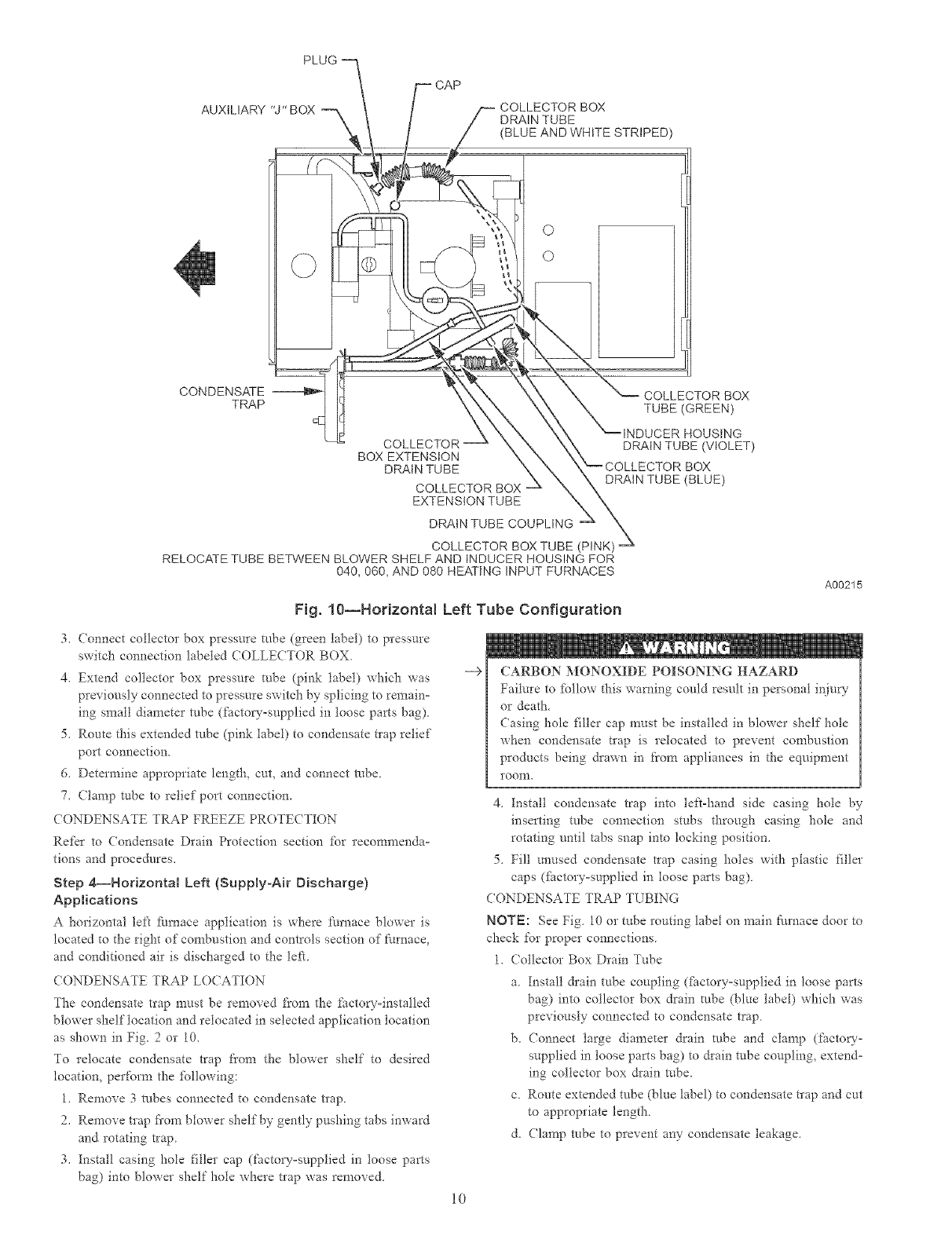
Fig. 10--Horizontal Left Tube Configuration
3. (onnect collector box pressure robe (green label) to pressure
switch connection labeled COLLECTOR BOX
4. Extend collector box pressure tube (pink label) which was
previously connected to pressure switch by splicing to remain°
lug small diameter robe (factoQ'-supplied in loose parts bag).
5. Route this extended robe (pink label) to condensate t_ap relief
port connection.
6. Determine appropriate length, cut, and connect robe.
7. Clamp robe to relief port connection.
CONDENSATE TRAP FREEZE PROTECTION
Refkr to Condensate Drain Protection section for recommenda°
tions and procedures.
Step 4--Horizontal Left {Supply-Ak Discharge)
Applications
A horizontal lef[ _mlace application is where furnace blower is
located to the right of combustion and controls section of furnace,
and conditioned air is discharged to the le_L
( ONDENSATE TRAP LO(ATION
The condensate tlap must be removed from the factor-installed
blower shelf location and relocated in selected application location
as shown in Fig. 2or 10.
To relocate condensate trap from the blower shelf to desired
location, perfom_ the fbllowing:
1. Remove 3 robes connected to condensate trap
2. Remove trap fi'om blower shelf by gently pushing tabs inward
and rotating trap
3. Instal! casing hole tiller cap (factory-supplied in loose parts
bag) into blower shelf hole where trap was removed.
-->
10
CARBON MONOXIDE POISONING HAZARD
Failure to follow this warning could result in personal injury
or death.
Casing hole filler cap must be installed in blower shelf hole
when condensate trap is relocated to prevent combustion
products being drawn in from appliances in the equipment
roonl.
4. [nstall condensate trap into left-hand side casing hole by
inserting robe connection stubs through casing hole and
rotating until tabs snap into locking position.
5. Fill unused condensate trap casing holes with plastic filler
caps di_ctory-supplied in loose parts bag).
CONDEXSATE TRAP TUBING
NOTI::: See Fig. 10 or tube routing label on main furnace door to
check for proper connections.
1. Collector Box Drain Tube
a. Install &ain tube coupling (_itctory-supplied in loose parts
bag) into collector box drain robe (blue label) which was
previously connected to condensate trap
b. Connect large diameter drain robe and clamp (factory-
supplied in loose parts bag) to drain robe coupling, extend-
ing collector box &ain robe.
c. Route extended tube (blue label) to condensate trap and cut
to appropriate length.
d. Clamp robe to prevent any condensate leakage.
2. InducerHousingDrainTube
a RemoveanddiscardLOWER(molded)inducerhousing
draintubewhichwaspreviouslyconnectedtocondensate
trap.
b.Useinducerhousing&ainextensiontube(violetlabeland
fhctoD--suppliedinloosepartsbag)toconnectLOWER
inducerhousing&ainconnectiontothecondensatetrap
c.Determineappropriatelength,cut,andconnectrobe.
d.(lamprobetopreventanycondensateleakage.
3.ReliefPortTube
a.Extendcollectorboxrobe(greenlabel)whichwasprevi=
ouslyconnectedtothecondensatetrapbysplicingtosmall
diameterrobe(fhctory=suppliedinloosepartsbag).
b.Routeextendedcollectorboxpressurerobetoreliefport
connectiononthecondensatetrap.
c.Determineappropriatelength,cut,andconnectrobe.
d.Clamprobetopreventanycondensateleakage.
CONDENSATETRAPFIELDDRAINATTACHMENTS
Referto CondensateDrainsectionfbr recommendationsand
procedures.
PRESSURESWIT(HTUBING
TheLOWERcollectorboxpressuretube(pinklabel)isfhctory
connectedtothepressure switch for use when Ihrnace is installed
in UPFLOW applications. This robe MUST be disconnected,
extended, rerouted, and then reconnected to the pressure switch in
HORIZONTAL LEFT applications.
NOTE: See Fig. 10 or tube routing label on main Nrnace door to
check for proper connections.
Modif}" robe as described below.
1. Disconnect collector box pressure tube (pink label) attached to
pressure switch.
2. Use smaller diameter tube (factov-supplied in loose parts
bag) to extend robe disconnected in item 1.
3. Route extended robe:
a. Behind inducer housing,
b. Between blowe* shelf" and inducer housing.
c. Behind inducer motor bracket.
d. Between inducer motor and pressure switch.
4. Detem_ine appropriate length, cut, and reconnect robe to
pressure switch connection labeled COLLECTOR BOX.
CONDENSATE TRAP FREEZE PROTECTION
Refer to Condensate Drain Protection section for recommenda°
tions and procedures.
CONSTRU(T A WORKING PLATFORM
Construct working platfbrm where all required Ihrnace clearances
are met, (See Fig. 3 and 11.)
[TNIT MAY NOT OPERATE
Failure to %llow this caution may result in intem_ittent unit
operation.
The condensate trap MUST be installed below furnace See
Fig 5 ibr dimensions. The drain connection to condensate
trap must also be properly sloped to an open &ain.
NOTE: Combustion-air and vent pipes are restricted to a mini°
mum length of 5 it. (See Table 7.)
--€
11
NOTE: A 12-in mininmm of_ket pipe section is recommended
with short (5 to 8 It) vent systems. This recommendation is to
reduce excessive condensate droplets fiom exiting the vent pipe,
(See Fig 11 or 34)
Step 5--Horizontal Right {Supply-Air Discharge)
Applications
A horizontal right furnace application is where furnace blowei is
located to the left of combustion and contlols section of ihmace,
and conditioned air is discharged to the right.
PROPERTY DAMAGE
Failure to ibllow this caution may result in minor property
damage
Local codes may require a drain pan under entire Ihrnace and
condensate trap when a condensing fhrnace is used in attic
application or over a finished ceiling.
NOTE: In Canada, installations shall be in accordance with
cun'ent NS(NGPI( Installation Codes and/or local codes
NOTE: The junction box (J-Box) MUST be relocated to opposite
side of furnace casing. (See Fig. 12.) See Electrical Connection
section for J-Box relocation.
CONDENSATE TRAP LOCATION
The condensate trap must be removed fi'om the fi_ctory°installed
blower shelf location and relocated in selected application location
as shown in Fig. 2 or 12,
To relocate condensate trap fiom the blowei shelf to desired
location, perfbnn the following:
1 Remove 3 tubes connected to condensate nap.
2. Remove trap from blower shetfby gently pushing tabs inward
and rotating trap.
3. Install casing hole filler cap (ihctory=supplied in loose parts
bag) into blower shelf hole where trap was removed.
CARBON MONOXIDE POISONING HAZARD
Failure to follow this warning coutd result in personal inju W
or death.
Casing hole filler cap must be installed in blower shelf" hole
when condensate trap is relocated to prevent combustion
products being drawn in from appliances in the equipment
roonl.
4. Install condensate trap into left=hand side casing hole by
inserting tube connection stubs through casing hole and
rotating until tabs snap into locking position.
5 Fill unused condensate tlap casing holes with plastic filler
caps (Pactory=supplied in loose parts bag).
CONDENSATE TRAP TUBING
NOTE: See Fig. 12 or robe routing label on main Ihrnace door to
check for proper connections
1 Collector Box Drain Tube
a Remove factory-installed plug from LOWER collector box
drain robe (blue and white striped label).
b Install removed clamp and plug into UPPER collector box
drain tube (blue label) which was previously connected to
condensate trap.
c Connect LOWER collector box drain tube (blue and white
striped label) to condensate trap Tube does not need to be
cut,
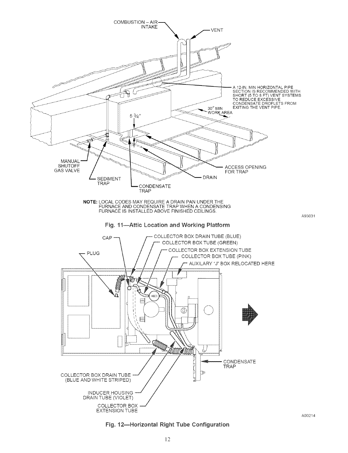
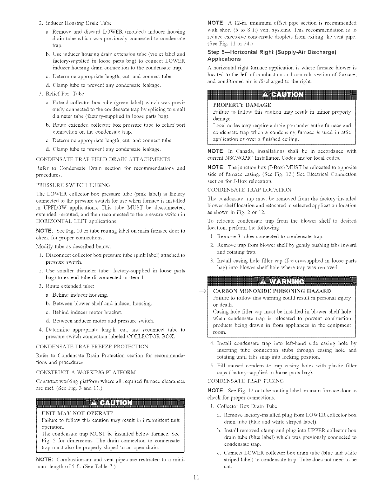
COMBUSTIONINTAKE
VENT
12-1N. MIN HORIZONTAL PIPE
SECTION iS RECOMMENDED WITH
SHORT (5 TO 8 FT) VENT SYSTEMS
TO REDUCE EXCESSIVE
CONDENSATE DROPLETS FROM
EXITING THE VENT PIPE.
SHUTOFF
GAS VALVE ACCESS OPENING
FOR TRAP
SEDIMENT
TRAP CONDENSATE
TRAP
DRAIN
NOTE: LOCAL CODES MAY REQUIRE A DRAIN PAN UNDER THE
FURNACE AND CONDENSATE TRAP WHEN A CONDENSING
FURNACE IS INSTALLED ABOVE FINISHED CEILINGS.
Fig. 11--Attic Location and Working Platform
BOX DRAIN TUBE (BLUE)
COLLECTOR BOX TUBE (GREEN)
BOX EXTENSION TUBE
COLLECTOR BOX TUBE (PINK)
RELOCATED HERE
A93031
COLLECTOR BOX DRAIN TUBE
(BLUE AND WHFE STRIPED)
CONDENSATE
TRAP
INDUCER
DRAINTUBE(VIOLET)
COLLECTOR BOX i'/
EXTENSION TUBE
Fig. 12--Horizonta{ Right Tube Configuration
A00214
12
d. (lamp robe to prevent any condensate leakage.
2. Inducer Housing Drain Tube
a Remove fhctoryoinstalled cap and clamp from LOWER
inducer housing drain connection.
b. Remove and discard UPPER (molded) inducer housing
drain robe which was previously connected to condensate
trap.
c. Install cap and clamp on UPPER inducer housing &ain
connection where molded &ain robe was removed.
d. Use inducer housing &ain extension tube (violet label and
factory-supplied in loose parts bag) to connect LOWER
inducer housing &ain connection to condensate trap.
e. Detem_ine appropriate length, cuL and connect robe to
condensate trap.
f\ Clamp tube to prevent any condensate leakage.
3. Relief Port Tube
Refer to Pressure Switch Tubing section for connection
procedure.
(ONDENSATE TRAP FIELD DRAIN ATTA(HMENT
Refer to Condensate Drain section %r recommendations and
procedures
PRESSURE SWITCH TUBING
One collector box pressure tube (pink label) is f'_ctory connected to
the pressnre switch fbr use when furnace is installed in UPFLOW
applications This tube MUST be disconnected and used for the
condensate trap relief port robe. The other collector box pressnre
robe (green label) which was fSctory connected to the condensate
trap relief port connection MUST be connected to the pressure
switch in DOWNFLOW or HORIZONTAL RIGHT applications
NOTE: See Fig. 12 or tube routing label on main filrnace door to
check for proper connections Relocate tubes as described below
1. Disconnect collector box pressure tube (pink label) attached to
pressure switch.
2. Extend collector box pressure tube (green label) which was
previously connected to condensate trap relief porq_connection
by splicing to small diameter robe (factov-supptied in loose
parts bag).
3. Route extended collector box pressure robe behind inducer
motor bracket then between inducer motor and pressure
switch,
4. Connect collector box pressm'e tube (green label) to pressure
switch connection labeled COLLE(TOR BOX.
5. Use remaining smaller diameter tube (gtctoryosupplied in
loose parts bag) to extend collector box pressure robe (pink
label) which was previously connected to pressure switch.
d. Route this extended robe (pink label) to condensate trap relief
port connection.
7. Detem_ine appropriate length, cut, and connect robe.
8. Clamp robe to relief port connection.
(ONDENSATE TRAP FREEZE PROTECTION
Re[kr to (ondensate Drain Protection section %r recommendao
tions and procedt/res.
(ONSTRUCT A WORKING PLATFORM
Construct working platfbm_ where all required furnace clearances
are met. (See Fig 3 and 11)
13
UPFLOW OR DOWNFLOW
V2" MAX
HORIZONTAL
A02146
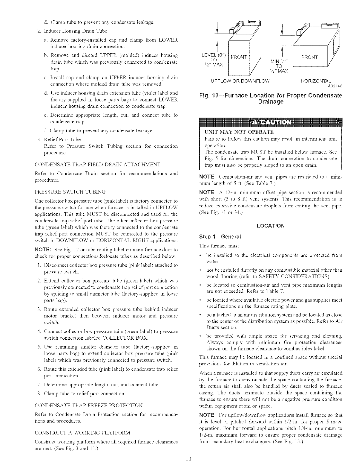
Fig. 13--Furnace Location for Proper Condensate
Drainage
UNIT MAY NOT OPERATE
Failure to [bllow this caution may result in intem_ittent unit
operation.
The condensate trap MUST be installed below furnace See
Fig. 5 for dimensions. The drain connection to condensate
trap must also be properly sloped to an open drain.
NOTE: (ombustionoair and vent pipes are restricted to a mini-
mun_ length of 5 ft. (See Table 7.)
NOTE: A 12oin. mininmm of_;et pipe section is recommended
with short (5 to 8 ft) vent systems. This recomn_endation is to
reduce excessive condensate droplets fi'om exiting the vent pipe.
(See Fig. 11 or 34.)
LOCATION
Step t--General
This furnace must
* be installed so the electrical components are protected from
water
not be installed directly on any combustible material other than
wood flooring (refer to SAFETY CONSIDERATIONS).
* be located so combustion-air and vent pipe n_aximum lengths
are not exceeded. Re[_r to Table 7.
* be located where available electric power and gas supplies meet
specifications on the furnace rating plate.
* be attached to an air distribution system and be located as close
to the center of the distribution system as possible. Re['cr to Air
Ducts section.
* be provided with ample space fbr servicing and cleaning.
Always comply with nainimun_ fire protection clearances
shown on the furnace clearance-toocombustibles label.
This fi_rnace may be located in a confined space without special
provisions fbr dilution or ventilation air.
When a fm'nace is installed so that supply/lucts caro- air circulated
by d_e ftm_ace to areas outside the space containing the f'umace.
the return air shall also be handled by ducts sealed to filrnace
casing. The &lcts terminate outside the space containing the
ft_rnace to ensure there will not be a negative pressure condition
within equipment room or space.
NOTE: For upflowidownflow applications install furnace so that
it is level or pitched [brward within 1i2oin. for proper furnace
operation. For horizontal applications pitch 1/4-in. minimtml to
1i2oin. maxinmnl forward to ensure proper condensate &ainage
from secondary heat exchangers. (See Fig. 13.)
---5
---5
BACK
A93043
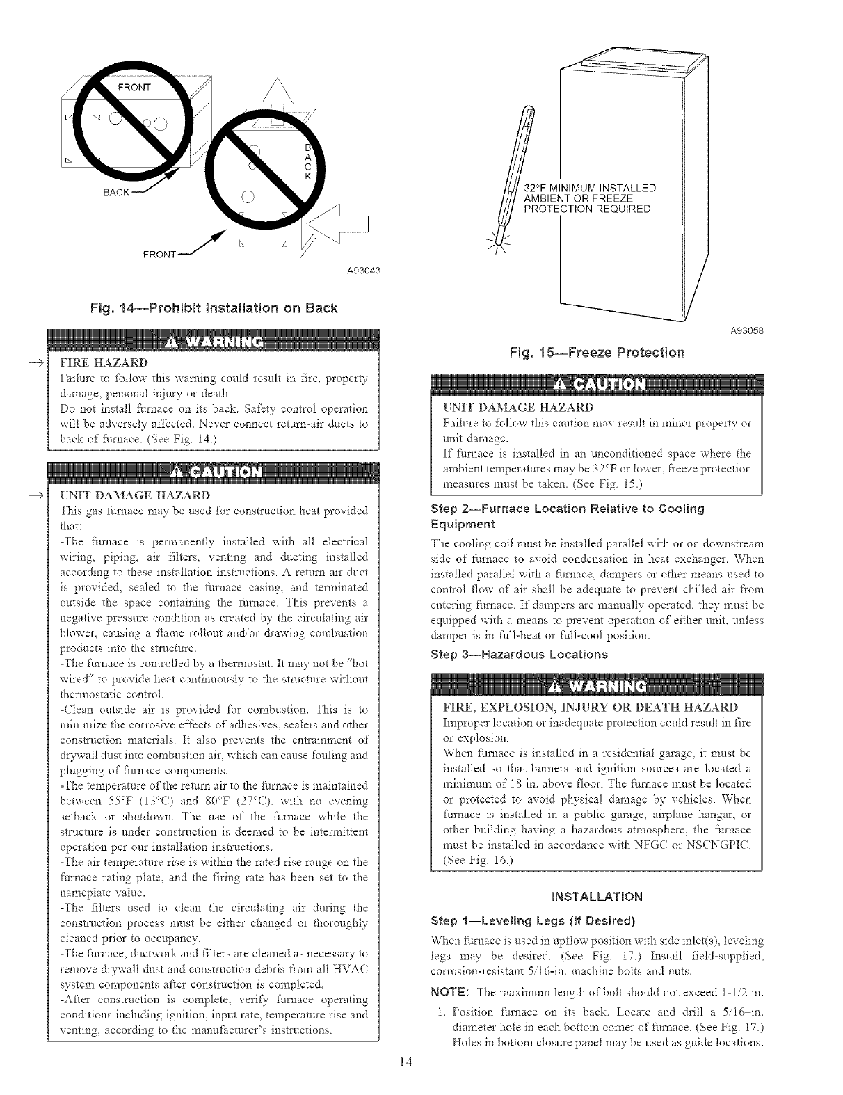
Fig. 14--Prohibit Installation on Back
FIRE HAZARD
Failure to %llow this warning could result in fire, property
damage, personal injury or death.
Do not install furnace on its back. Safety control operation
will be adversely affected. Never connect return=air ducts to
back of Nmace. (See Fig. 140
[TNIT DAMAGE HAZARD
This gas fire, ace may be used fbr construction heat provided
that:
-The ftm_ace is permanently installed with all electrical
wiring, piping, air filters, venting and ducting installed
according to these installation instructions. A retnrn air duct
is provided, sealed to the furnace casing, and terminated
outside the space containing the fkmlace. This prevents a
negative pressure condition as created by the circulating air
blower, causing a flame rollout and/or &awing combustion
products into the stl_acture.
-The furnace is controlled by a thermostat. It may not be "hot
wired" to provide heat continuously to the strt/cture without
thermostatic control.
-(lean outside air is provided for combustion. This is to
minimize the corrosive effects of adhesives, sealers and other
construction materials. It also prevents the entrainment of
dwwall dust into cornbusfion air, which can cause %uling and
plugging of Nmace components.
-The temperature of the return air to the fhmace is maintained
between 55cT (13c>() and 80°F (27_>(), with no evening
setback or shutdown. The use of the Nmace while the
stl_acture is under construction is deemed to be intermittent
operation per our installation instructions.
-The air temperature rise is within the rated rise range on the
furnace rating plate, and the firing rate has been set to the
nameplate value.
-The filters used to clean the circulating air during the
construction process nmst be either changed or thoroughly
cleaned prior to occupancy.
-The Nmace, ductwork and filters are cleaned as necessary to
remove &ywall dust and construction debris t)om all HVAC
system components after construction is completed.
-After construction is complete, verify Nmace operating
conditions including ignition, input rate, temperature rise and
venting, according to the manufi_cmrer's instluctions.
A93058
Fig. 15--Freeze Protection
M
[NIT DAMAGE HAZARD
Failure to £bllow this caution may result in minor property or
unit damage.
If Nrnace is installed in an unconditioned space where the
arnbient temperatures may be 3UT or lower, fi'eeze protection
measures must be taken. (See Fig. 15.)
Step 2--Furnace Location Relative to Cooting
Equipment
)"he cooling coil must be installed parallel with or oll downstream
side of t:urnace to avoid condensation in heat exchanger. When
installed parallel with a fi/mace, dampers or other means used to
control flow of air shall be adequate to prevent chilled air from
entering t:urnace. If dampers are manually operated, they must be
equipped with a means to prevent operation of either unit, unless
damper is in fgll=heat or full-cool position.
Step a--Hazardous Locations
14
FIRE, EXPLOSION, IN J[ RY OR DEATH HAZARD
Improper location or inadequate protection could result in fire
or explosion
When fhmace is installed in a residential garage, it must be
installed so that burners and ignition sources are located a
mininmn_ of 18 in. above floor. The fi/mace must be located
or protected to avoid physical damage by vehicles. When
ft_rnace is installed in a public garage, airplane hangar, or
other building having a hazardous atmosphere, the t'umace
must be installed in accordance with NFGC or NS(NGPIC.
(See Fig. 16.)
mNSTALLATION
Step l--Leveling Legs {ff Desired)
When f_/rnace is nsed in upftow position with side inlet(s), leveling
legs may be desired. (See Fig. I7.) Install field-supplied,
corrosion-resistant 5/16°in machine bolts and nuts.
NOTE: The maximum length of bolt should not exceed 1-1/2 in.
1. Position furnace on its back. Locate and drill a 5/16 in.
diameter hole in each bottom corner of furnace. (See Fig. 17.)
Holes in bottom closure panel may be used as guide locations.
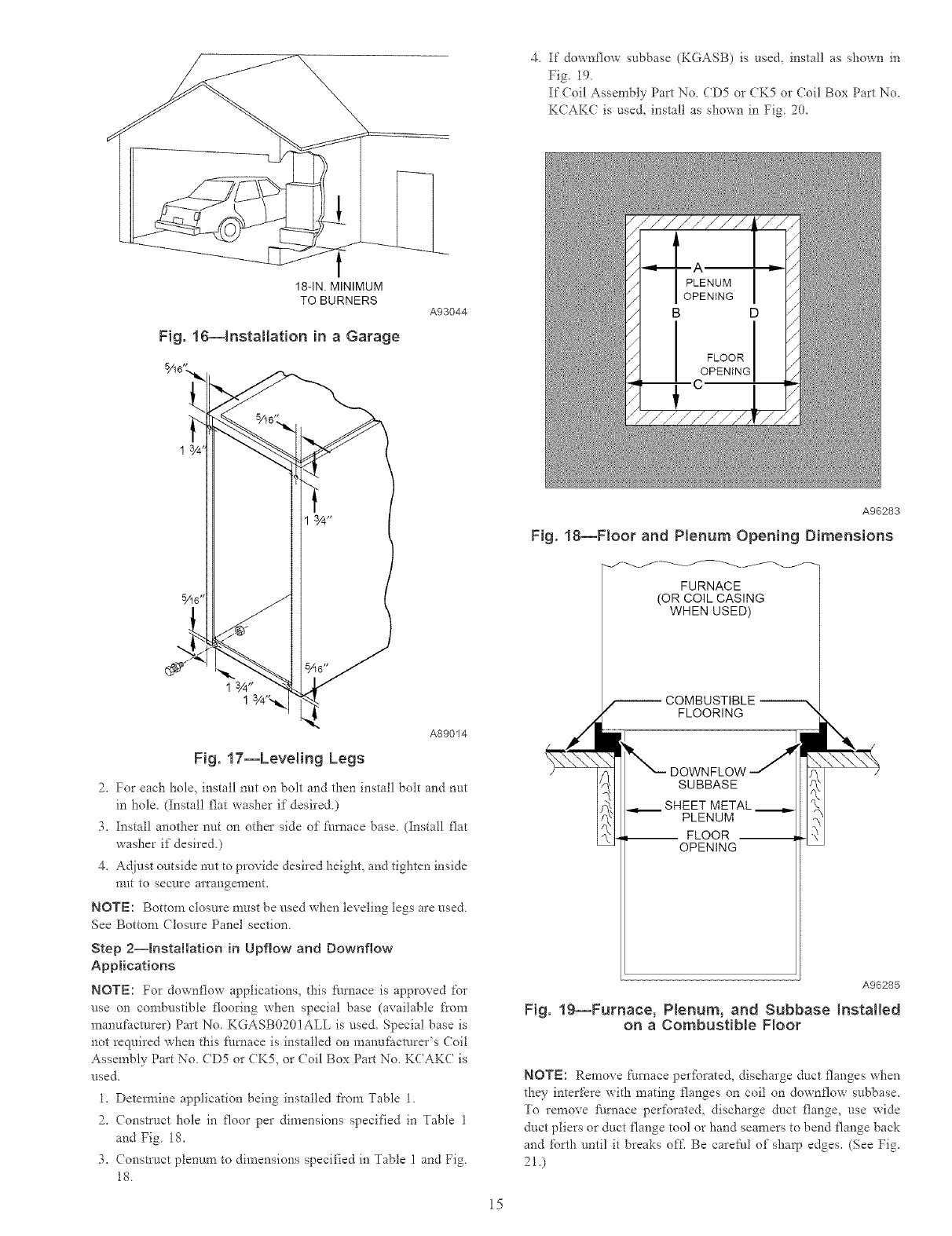
4 If downflow subbase (KGASB) is use& install as shown in
Fig. 19
If (?oil Assembly Part No, (D5 or CK5 or (?oil Box Part No,
K(AK( is use& install as shown in Fig 20_
18-IN. MINIMUM
TO BURNERS
Fig. 16--Installation in a Garage
A93044
A89014
Fig. 17--Leveling Legs
2_ For each hole. install nut on bolt and then install bolt and nut
in hole_ (Install flat washer if desired.)
3_ Install another nut on other side of fi/rnace base. (Install flat
washer if desired.)
4. Adjust outside nut to provide desired height, and tighten inside
nut to secure arrangement.
NOTE: Bottom closure must be used when leveling legs are used.
See Bottom Closure Panel section.
Step 2--Installation in Upflow and Downflow
Applications
NOTE: For downt'tow applications_ this fllmace is approved for
use on combustible flooring when special base (available from
manu_acmrer) Part No. KGASB0201ALL is used. Special base is
not required when this :[ilmace is installed on manu_hcmrer's (?oil
Assembly Part No. CD5 or CK5, or (?oil Box Part No. KCAKC is
used.
1. Detemaine application being installed t'rom Table 1.
2. Construct hole in floor per dimensions specified in Table 1
and Fig. 18.
3. (onstruct plenum to dimensions specified in Table 1 and Fig.
18.
15
A96283
Fig. 18--Floor and Plenum Opening Dimensions
FURNACE
(OR COIL CASING
WHEN USED)
COMBUSTIBLE
FLOORING "_
DOWNFLOW
SUBBASE
SHEET METAL
PLENUM
-- FLOOR --
OPENING
A96285
Fig. 1g--Furnace, Plenum, and Subbase Installed
on a Combustib{e Floor
NOTE: Remove furnace per_brated, discharge duct flanges when
they inter['_re with mating flanges on coil on downflow subbase.
To remove fl/mace perforate& discharge duct flange, use wide
duct pliers or duct flange tool or hand seamers to bend flange back
and forth until it breaks off. Be carefl/t of sharp edges. (See Fig.
21)
FURNACE
CASBNG
WIDTH
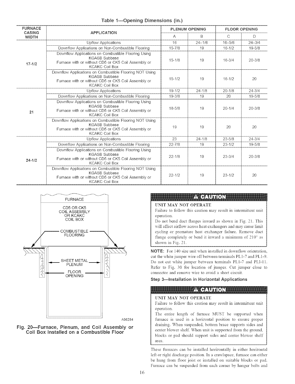
Table 1--OpeNng Dimensions (in.)
APPLICATION FLOOR OPENING
D
24-3/4
19-5/8
PLENUM OPENING
A B
16 24-1/8
15-7/8 19
15-1/8 19
15-1/2 19
19-1/2 24-1/8
19-3/8 19
18-5/8 19
19 19
23 24-1/8
22-7/8 19
22-1/8 19
22-1/2 19
C
Upflow Applications 16-5/8
Downflow Applications on Non-Combustible Flooring 16-1/2
Downflow Applications on Combustible Flooring Using
KGASB Subbase 16-3/4 20-3/8
17-112 Furnace with or without CD5 or CK5 Coil Assembly or
KCAKC Coil Box
Downflow Applications on Combustible Flooring NOT Using
KGASB Subbase
Furnace with or without CD5 or CK5 Coil Assembly or 16-1/2 20
KCAKC Coil Box
Upflow Applications 20-1/8 24-3/4
Downflow AppIications on Non-Combustible Flooring 20 1%5/8
Downflow Applications on Combustible Flooring Using
KGASB Subbase 20-1/4 20-3/8
21 Furnace with or without CD5 or CK5 Coil Assembly or
KCAKC Coil Box
Downflow Applications on Combustible Flooring NOT Using
KGASB Subbase
Furnace with or without CD5 or CK5 Coil Assembly or 20 20
KCAKC Coil Box
Upflow Applications 23-5/8 24-3/4
Downflow Applications on Non-Combustible Flooring 23-1/2 1%5/8
Downflow Applications on Combustible Flooring Using
KGASB Subbase 23-3/4 20-3/8
24-112 Furnace with or without CD5 or CK5 Coil Assembly or
KCAKC Coil Box
Downflow Applications on Combustible Flooring NOT Using
KGASB Subbase
Furnace with or without CD5 or CK5 Coil Assembly or 23-1/2 20
KCAKC Coil Box
FURNACE
CD5 OR CK5
COIL ASSEMBLY
OR KCAKC
COIL BOX
/_ COMBUSTIBLE
FLOORING "k
SHEET METAL ._,.
PLENUM
__ FLOOR __
OPENING
A96284
Fig. 20--Furnace, Plenum, and Coil AssemNy or
Coil Box Installed on a Combustib{e Floor
16
[TNIT MAY NOT OPERATE
Failure to %ltow this caution may result in intem_ittent unit
operation.
Do not bend duct flanges inward as shown in Fig 2! This
will affect airflow across heat exchangers and may cause limit
cycling or premature heat exchanger _itilure, Remove duct
flange completely or bend it inward a minimum of 2!0 ° as
shown in Fig, 21
NOTE: For 140 size unit when installed in downflow orientation,
cut the white jumper wire offbetween terminals PL]-7 and PLI=9.
Do not cut white jumper between tem_inals PLI=7 and PLI-11.
Refer to Fig. 30 _br location of jumper (ut jumper close to
connector and remove wire to avoid a short circuit
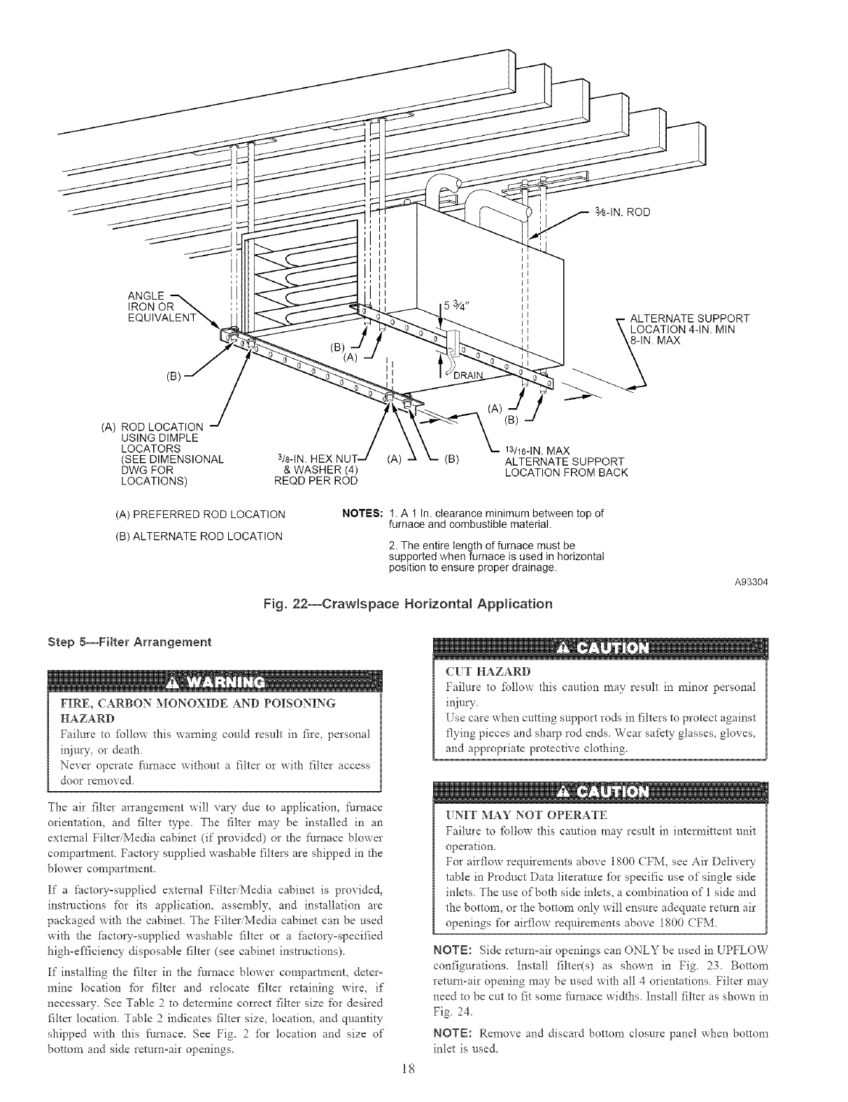
Step a--installation in Horizontal Applications
UNIT MAY NOT OPERATE
Failure to _bltow this caution may result in intem_ittent unit
operation.
The entire length of _i/rnace MUST be supported when
furnace is used in a horizontal position to ensure proper
draining. When suspended, bottom brace supports sides and
center blower shelf When unit is supported fi'om the ground,
blocks or pad should support sides and center blower shelf
area.
These fmnaces can be installed horizontally in either horizontal
te_ or right discharge position. In a crawlspace, t'm'nace can either
be hung from floor joist or installed on suitable blocks or pad.
Furnace can be suspended flora each corner by hanger bolts and
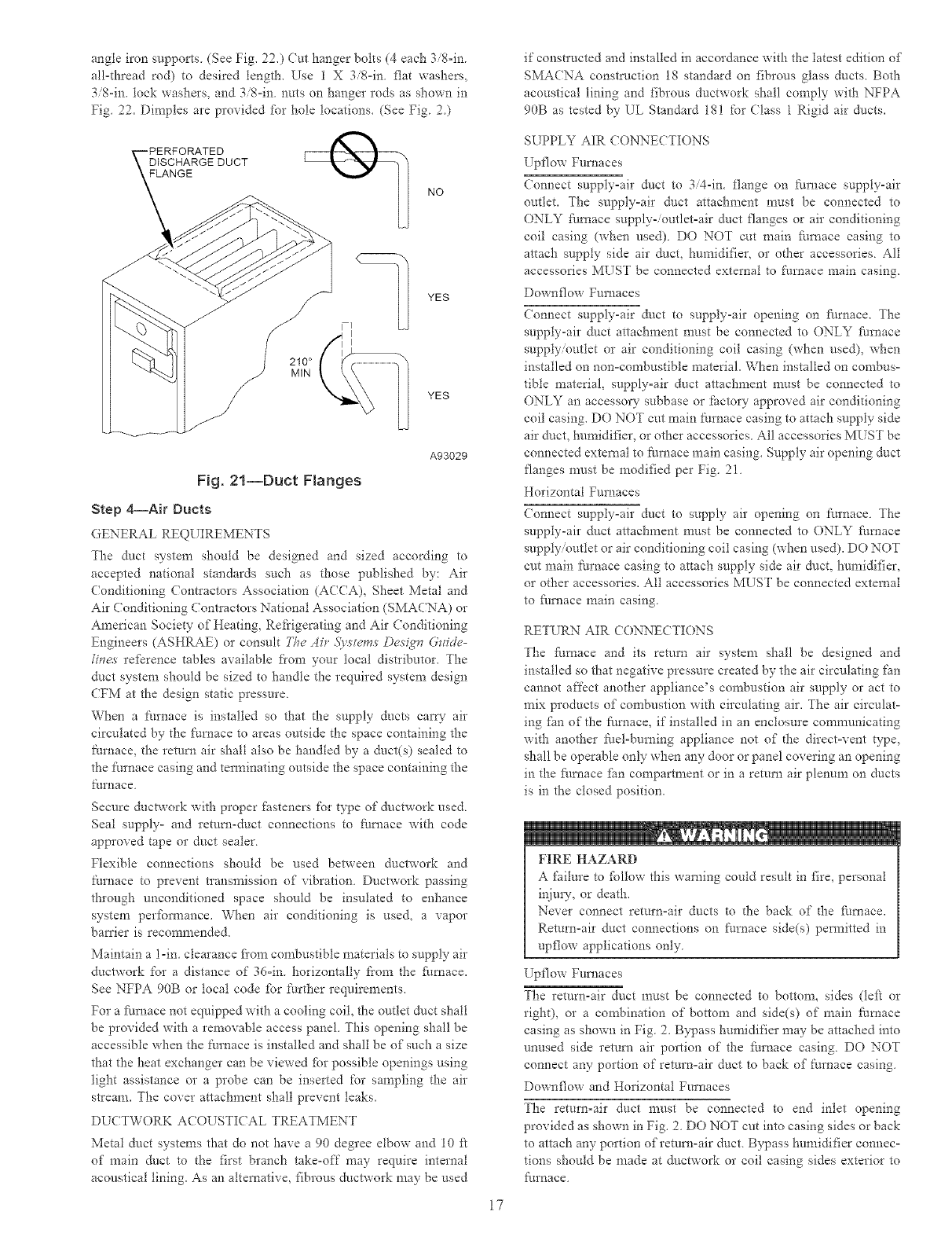
angle iron s_/pports (See Fig. 22.) Cut hanger bolts (4 each 3/8=in.
all=thread rod) to desired tength. Use 1 X 3/8=in flat washers,
3/8-in. tock washers, and 3/8=in nuts on hanger rods as shown in
Fig 22. Dimples are provided fbr hole locations. (See Fig 2)
if constructed and installed in accordance with the latest edition of
SMAENA construction 18 standard on fibrous glass ducts. Both
acoustical lining and fibrous ductwork shall comply with NFPA
90B as tested by EL Standard 18! for (?lass 1 Rigid air ducts.
DISCHARGE DUCT
FLANGE
210°
MIN
NO
YES
YES
A93029
Fig. 21--Duct Flanges
Step 4--Air Duets
GENERAL REQUIREMENTS
The duct system should be designed and sized according to
accepted national standards such as those published by: Air
Conditioning Contractors Association (ACCA), Sheet Metal and
Air Conditioning ContIactors National Association (SMACNA) or
American Society of Heating, Refrigerating and Air Conditioning
Engineers (ASHRAE) or consult Fhe Air 51v,ste_sDesiglv G_ide-
trees rel:_rence rabies available fiom your local distributor. The
duct system should be sized to handle the required system design
CFM at the design static pressure.
When a furnace is installed so that the supply ducts catty- air
circulated by the t:urnace to areas outside the space containing the
Nrnace, the return air shall also be handled by a duct(s) sealed to
the furnace casing and tem_inating outside the space containing the
furp, ace
Secure ductwork with proper fasteners for type of ductwork used.
Seal supply- and return-duct connections to furnace with code
approved tape or duct sealer.
Flexible connections should be used between ductwork and
furnace to prevent tlansmission of vibration. Ductwork passing
through unconditioned space should be insulated to enhance
system performance. When air conditioning is used, a vapor
battier is recommended.
Maintain a l-in. clearance fi'om combustible materials to supply air
ductwork for a distance of 36=in. horizontally fiom the furnace.
See NFPA 90B or local code fbr further requirements.
For a fhmace not equipped with a cooling coil, the outlet duct shall
be provided with a removable access panel. This opening shall be
accessible when the t:urnace is installed and shall be of such a size
that the heat exchanger can be viewed fbr possible openings using
light assistance or a probe can be inserted for sampling the air
stream. The cover attachment shall prevent leaks.
DUCTWORK ACOUSTIE AL TREATMENT
Metal duct systems that do not have a 90 degree elbow and 10 ft
of main duct to the first branch take-off may require internal
acoustical lining. As an aheraative, fibrous ductwmk may be used
SUPPLY AIR CONNECTIONS
Upflow Furnaces
Connect supply=air duct to 3/4-in. flange on furnace supply-air
outlet. The supply=air duct attachment must be connected to
ONLY fhmace supply-/outlet=air duct flanges or air conditioning
coil casing (when used) DO NOT cut main fhmace casing to
attach supply side air duct, humidifier, or other accessories All
accessories MUST be connected external to furnace main casing.
Downflow Furnaces
(onnect supply-air duct to supply-air opening on fllrnace. The
supply-air duct attachment must be connected to ONLY fhrnace
supply/outlet or air conditioning coil casing (when used), when
installed on non=combustible material. When installed on combus-
tible material, supply=air duct attachment must be connected to
ONLY an accessory subbase or Pactory approved air conditioning
coil casing. D() NOT cut main furnace casing to attach supply side
air duct, humidifier, or other accessories. All accessories MUST be
connected external to furnace main casing. Supply air opening duct
flanges must be modified per Fig. 21.
Horizontal Furnaces
Connect supply=air duct to supply air opening on furnace. The
supply-air duct attachment must be connected to ONLY fhmace
supply/outlet or air conditioning coil casing {when used). DO NOT
cut main furnace casing to attach supply side air duct, humidifier,
or other accessories. All accessories MUST be connected external
to fhrnace main casing.
RETURN AIR CONNECTIONS
The furnace and its return air system shall be designed and
installed so that negative pressure created by the air circulating fan
cannot affect another appliance's combustion air supply or act to
mix products of combustion with circulating air. The air circulat-
ing fhn of the furnace, if installed in an enclosure communicating
with another filel=buming appliance not of the direct=vent type,
shall be operable only when any door or panel covering an opening
in the fhmace fhn compartment or in a return air plenum on ducts
is in the closed position.
FIRE HAZARD
A failure to _bltow this warning could result in fire, personal
injury, or death.
Never connect return=air ducts to d_e back of the _hmace.
Return=air duct connections on furnace side{s) peimitted in
upflow applications only
Upflow Furnaces
The return-air duct mttst be connected to bottom, sides (le_:_ or
right), or a congbination of bottom and side(s) of main furnace
casing as shown in Fig. 2. Bypass humidifier may be attached into
unused side return air portion of the furnace casing DO NOT
connect any portion of return=air duct to back of furnace casing
Downflow and Horizontal Furnaces
The return=air duct must be connected to end inlet opening
provided as shown in Fig. 2. DO NOT cut into casing sides or back
to attach any portion of return-air duct. Bypass humidifier connec-
tions should be made at ductwork or coil casing sides exterior to
furnace
17
ANGLE
IRON OR
EQUIVALENT
3/8-1N.ROD
ALTERNATE SUPPORT
LOCATION 4-IN. MIN
8-IN. MAX
(B)
(A) ROD LOCATION
USING DIMPLE
LOCATORS
(SEE DIMENSIONAL
DWG FOR
LOCATIONS)
3/8-1N.HEX
& WASHER (4)
REQD PER ROD
(B) ALTERNATE SUPPORT
LOCATION FROM BACK
(A) PREFERRED ROD LOCATION
(B) ALTERNATE ROD LOCATION
NOTES: 1. A 1 In. clearance minimum between top of
furnace and combustible material.
2. The entire length of furnace must be
supported when furnace is used in horizontal
position to ensure proper drainage.
Fig. 22--Crawlspace Horizonta{ ApNication
A93304
Step 5--Filter Arrangement
FIRE, CARBON MONOXIDE AND POISONING
HAZARD
Failure to %llow this warning co_dd result in fire_ personal
injur?% or death
Never operate fi/rnace without a filter or with filter access
door removed.
The air filter an'angement will va N" due to application, furnace
orientation, and filter type. The filter may be installed in an
external Filter/Media cabinet (if provided) or the t'umace blower
compartment. Facto_ supplied washable filters are shipped in the
blower compartment.
If a factoryosupplied external Filter Media cabinet is provided,
instructions for its application, assembly, and installation are
packaged with the cabinet. The Filter/Media cabinet can be used
with the fitctoryosupplied washable filter or a factor'-specified
highoefficiency disposable filter (see cabinet instructions)
If installing the filter in the t_urnace blower compartment, deter-
mine location %r filter and relocate filter retaining wire, if
necessary. See Table 2 to determine correct filter size for desired
filter location. Table 2indicates filter size, location, and quantity
shipped with this filrnace. See Fig. 2 %r location and size of
bottom and side returnoair openings.
18
(IT HAZARD
Failure to %llow this caution may result in minor personal
ir!iury
Use care when cutting support rods in filters to protect against
flying pieces and sharp rod ends. Wear safety glasses, gloves,
and appropriate protective clothing.
[TNIT MAY NOT OPERATE
Failure to fc4tow this caution may result in intem_ittent unit
operation.
For airflow requirements above 1800 CFM, see Air Deliver-
table in Prodnct Data literature %r specific use of single side
inlets The use of both side inlets, a combination of 1 side and
the bottom, or the bottom only will ensure adequate return air
openings for airflow requirements above 1800 CFM.
NOTE: Side remrnoair openings can ONLY be used in UPFLOW
configurations. Install filter(s) as shown in Fig 23 Bottom
return-air opening may be used with all 4 orientations. Filter may
need to be cut to fit some furnace widths. Install filter as shown in
Fig. 24.
NOTE: Remove and discard bottom closure panel when bottom
inlet is used.
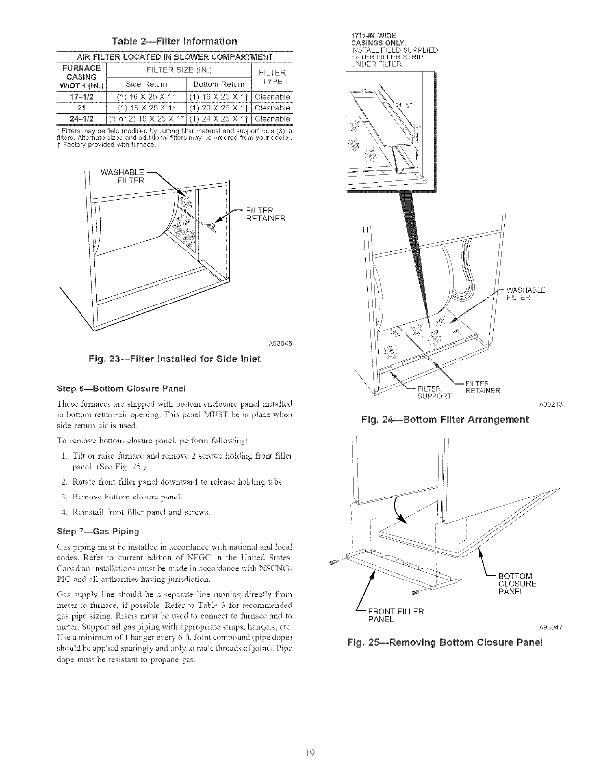
Table 2--FHter Information
AmR FBLTER LOCATED }N BLOWER COMPARTMENT
FURNACE FILTER SIZE (IN.) FILTER
CASBNG
WIDTH {IN.) Side Return Bottom Return TYPE
17=112 (1) 16 X 25X 11. (1) 16 X 25 X 11- CleanaNe
21 (1) 16X25X 1" (1) 20X25X 11- Cleanabte
24=112 (1 or 2) 16X25X1* (1) 24X25X 11- Cleanabie
* Filters may be field modified by cutting filter matedal and support rods (3) in
filters Alternate sizes and additional filters may be ordered from your dealer
? Factory-provided with furnace.
17_-IN.WIDE
CASINGS ONLY:
INSTALL FELD-SUPPLIED
FILTER FILLER STRIP
UNDER FILTER.
FILTER
RETAINER
\
Fig. 23--FiRer Installed for Side INet
A93045
Step 6--Bottom Closure PaneJ
These f_tmaces are shipped with bottom enclosure panel installed
in bottom return=air opening This panel MUST be in place when
side return air is used,
To remove bottom closure panel, perfbm_ _bllowing:
l, Tilt or raise tin'hate and remove 2 screws holding flont filler
panel, (See Fig 25,)
2, Rotate front filler pane1 downward to release holding tabs
3, Remove bottom closure pane1
4, Reinstall fi'ont _lle* panel and screws,
Step 7--Gas Piping
Gas piping must be installed in accordance with national and local
codes. Refer to cmTent edition of NFG( iu the United States.
(anadian iustallations must be made iu accordance with NSCNG=
PIC and all authorities having jurisdiction.
Gas supply line should be a separate line rurming directly t'rom
meter to furnace, if possible. RefEr to Table 3 _br recommended
gas pipe sizing Risers must be used to cormect to _i/rnace aud to
meter. Support all gas piping with appropriate straps, hangers, etc
Use a minimum of I hanger ever?" 6 t't. Joint con_pound (pipe dope)
should be applied sparingly and only to male threads of joints. Pipe
dope must be resistant to propane gas.
=WASHABLE
FILTER
SUPPORT
FILTER
RETAINER
Fig. 24_Bottom FHter Arrangement
A00213
}
BOTTOM
CLOSURE
PANEL
FRONT FILLER
PANEL
A93047
Fig. 2g--Removing Bottom Closure Panel
19
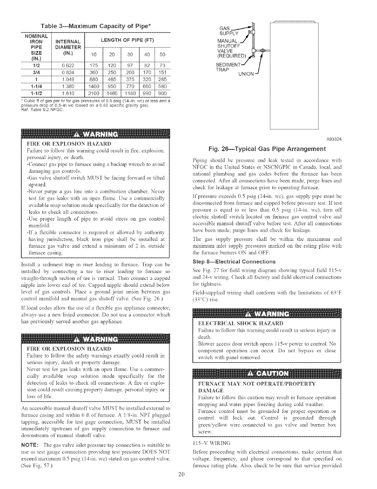
TaNe 3--Maximum Capacity of Pipe*
NOMINAL
IRON
PIPE
SmZE
ON.)
I/2
3/4
I
1-1/4
1-1t2
iNTERNAL
DIAMETER
(IN.)
0.622
0.824
1.049
1.380
1.610
LENGTH OF PIPE (FT}
10 20 30 40 50
175 120 97 82 73
360 250 200 170 151
680 465 375 320 285
1400 950 770 660 580
2100 1460 1180 990 900
* Cubic ft of gas per hr for gas pressures of 0.5 psig (14-in wc) or less and a
pressure drop of 0.5-in wc (based on a 060 specific gravity gas).
Ref: Table 9.2 NFGC.
FIRE OR EXPLOSION HAZARD
Failm'e to %llow this wa*ning could result in fire, explosion,
personal inju W, or death
-(onnect gas pipe to 5n'nace using a backup wrench to avoid
damaging gas controls.
-Gas valve shutoff switch MUST be fhcing fbrward or tilted
upward.
-Never pu*ge a gas line into a combustion chamber. Never
test for gas leaks with an open flame. Use a commercially
available soap solution made specifically for the detection of
leaks to check all connections.
-Use proper length of pipe to avoid stress on gas control
manifbld.
-If a /'lexible connector is required or allowed by attthori w
having jurisdiction, black iron pipe shall be installed at
fimaace gas valve and extend a mininmm of 2 in outside
furnace casing.
Install a sediment trap in riser leading to fl/mace. Trap can be
installed by connecting a tee to riser leading to t\u'nace so
straight-through section of tee is vertical Then connect a capped
nipple into lower end of tee. (apped nipple should extend below
level of gas controls. Place a ground joint union between gas
control manifold and manual gas shutoff valve. (See Fig 26.)
If local codes allow the use of a flexible gas appliance connector,
always use a new listed connector. Do not use a connector which
has previously served another gas appliance.
FIRE OR EXPLOSION HAZARD
Failure to f\fllow the safkty warnings exactly could result in
serious injury, death or property damage
Never test for gas leaks with an open flame. Use a commer-
cially available soap solution made specifically for the
detection of leaks to check all connections A fire or explo°
sion could result causing property damage, personal ir!iury or
toss of life
An accessible manual shutoff valve MUST be installed external to
fl/mace casing and within 6 ft of filmace. A li8°in. NPT plugged
tapping, accessible for test gage connection, MLST be installed
immediately upstream of gas supply connection to furnace and
downstIeam of manual shutoff valve
NOTE: The gas valve inlet pressure tap connection is suitable to
use as test gauge connection providing test pressure DOES NOT
exceed maximum 0.5 psig (14-in. wc) stated on gas control valve
(See Fig. 57)
GAS
SUPPLY
MANUAL _/ II
f
A93324
Fig. 26--Typical Gas Pipe Arrangement
Piping should be pressure and leak tested in accordance with
NFG( in the United States or NSCNGPI( in Canada. local, and
national plumbing and gas codes be_;ore the t'urnace has been
connected. After all connections have been made. purge lines and
check for leakage at furnace prior to operating t:urnace.
If pressure exceeds 0.5 psig (14=in. wc), gas supply pipe must be
disconnected from ftlrnace and capped be_bre pressure test If test
pressure is equal to or less than 0.5 psig (14=in. wc), turn off
electIic shutoff switch located on _hrnace gas control valve and
accessible manual shutoff valve before test After all connections
have been made, purge lines and check fbr leakage.
The gas supply pressure shall be within the maximum and
minimum inlet supply pressures marked on the rating plate with
the fl/rnace burners ON and OFF.
Step 8--Electrical Connections
See Fig 27 for field wiring diagram showing typical field 115-v
and 24-v wiring (hock all fhctoo" and field electrical connections
for tightness
Field=supplied wiring shall conform with the limitations of 63_T
(33°(7) rise.
ELECTRICAL SHOCK HAZARD
Failure to follow this warning could result in serious injury or
death
Blower access door switch opens 115-v power to control. No
component operation can occur Do not bypass or close
switch with panel removed
2O
FURNACE MAY NOT OPERATE/PROPERTY
DAMAGE
Failure to %llow this caution may result in fhraace operation
stopping and water pipes freezing during cold weather.
Furnace control must be grounded for proper operation or
control will lock out. (ontrol is grounded through
green yellow wire connected to gas valve and burner box
SCrew,
115 V WIRING
Be_bre proceeding with electrical connections, make certain that
voltage, fi'equency, and phase con'espond to that specified on
furnace rating plate. Also, check to be sure that service provided
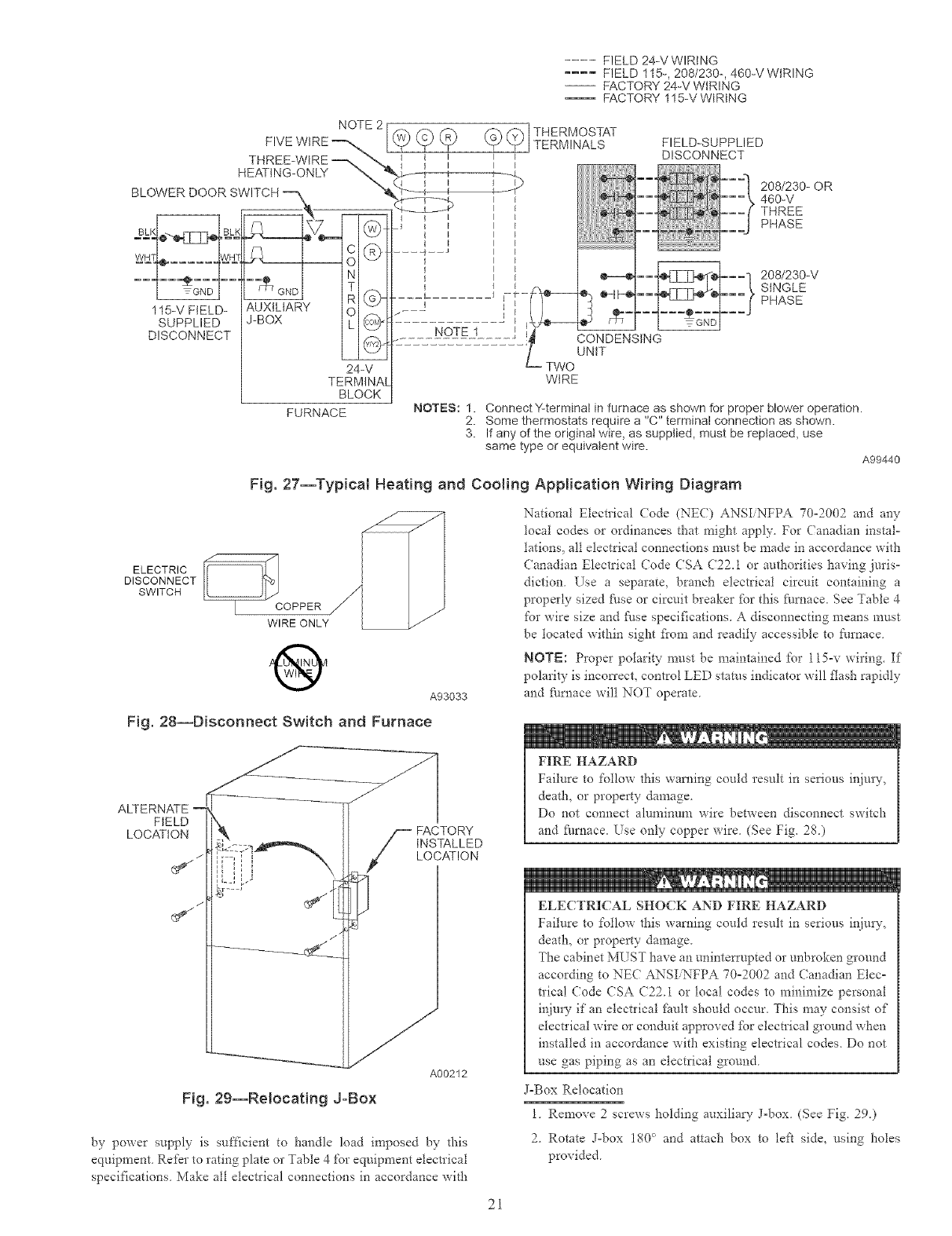
.... FIELD 24-V WIRtNG
.... FIELD 115-, 208/230-, 460-V WtRING
-- FACTORY 24-V WIRING
-- FACTORY 115-VWtRtNG
NOTE 2 I
FIVEW RE-- I
THREE-WIRE _
HEATING-ONLY _
7¿ :
q
115-V FIELD- AUXILIARY O F.
SUPPLIED J-BOX h_
DISCONNECT @
24-V
TERMINAL
BLOCK
FURNACE NOTES: 1. Connect Y-terminal in furnace as shown for proper blower operation.
2. Some thermostats require a "C" terminal connection as shown.
3. If any of the original wire, as suppled, must be replaced, use
same type or equivalent wire. A99440
Fig. 27--Typical Heating and Cooling Application Wiring Diagram
ELECTRIC _C
DISCONNECT
SWITCH
OPPER
WIRE ONLY
®A93033
National Electlical (:ode (NEC) ANSIiNFPA 70-2002 and any
local codes or ordinances that might apply For Canadian instal-
tations, all electrical connections must be made in accordance with
Canadian Electrical (?ode CSA (722,1 or authorities having juris-
diction, Use a separate, branch electrical circuit containing a
properly sized _ase or circuit breaker _br this fl/mace, See Table 4
for wire size and t:ime specifications. A disconnecting means must
be located within sight fiom and readily accessible to Nrnace,
NOTE: Proper polarity must be maintained for 115-v wiring. If
polarity is incon'ect, control LED stares indicator will flash rapidly
and _arnace will NOT operate,
Fig. 28--Disconnect Switch and Furnace
ALTERNATE --
FIELD
LOCATION
_J
S ACTORY
INSTALLED
LOCATION
Y
A00212
Fig. 29--Relocating J-Box
by power supply is sufficient to handle load imposed by this
equipment Refer to rating plate or Table 4 for equipment electrical
specifications Make all electrical connections in accordance with
FIRE HAZARD
Failure to fd!ow this warning could result in serious inju U,
death, or property damage
Do not connect alun_inun_ wire between disconnect switch
and _i/rnace, Use only copper wire (See Fig, 28)
ELECTRICAL SHOCK AND FIRE HAZARD
Failure to follow this warning could result in serious inju W,
death, or property damage,
The cabinet MUST have an unintetTupted or unbroken ground
according to NEC ANSI NFPA 70-2002 and ( anadian Elec-
trical (ode (SA (22i or local codes to minimize personal
injm'y if an electrical limit should occur, This may consist of
electrical wire or condtdt approved _Pr electrical ground when
installed in accordance with existing electrical codes Do not
use gas piping as an electrical ground
J-Box Relocation
1, Remove 2 screws holding auxiliaQ" J-box (See Fig. 29,)
2Rotate J-box 180 ° and attach box to left side, using holes
provided
2i
ELECTRICAL SHOCK AND FIRE HAZARD
Failure to billow this warning could result in serious injury,
death, or property damage.
If manual disconnect switch is to be mounted on furnace,
select a location where a drill or ihstener will not contact
electrical or gas components
24 V WIRING
(onnect 24-v thermostat leads to 24ov terminal block on t:urnace
control. For proper cooling operation, Y wire from thermostat
MUST be connected Go YY2 tem_inal on fhmace control, as
shown in Fig. 27 The 24=v terminal block is marked l\_r easy
connection of field wiring. (See Fig 30) The 24ov circuit contains
a 3-amp, automotive-type fuse located on flul_ace control. (See
Fig. 31.) Any electrical shorts of 24-v wiring during installation,
service, or n_aintenance may cause t:use to blow If fuse replace°
ment is required, use only a ihse of identical size (3 amp) and type
The control will flash code 24 when fuse needs replacement.
NOTE: Use AWG No. 18 color-coded copper them_ostat wire
ibr lengths up to 100 it. For wire lengths over 100 if, use AWG No.
15 wire.
AC( ESSORIES
1. Electronic Air (leaner (EAC)
Two quick-connect terminals marked EAC-1 and EACo2 are
provided for EAC connection. (See Fig 3 I.) These terminals
are energized with 115-v (i 0oamp rnaxinmm) during blower
motor operation.
UNIT MAY NOT OPERATE
Failure to follow this caution may result in intermittent
operation or performance satisfa_ction
DO NOT connect _hmace contlol HUM terminal to HUM
(humidifier) terminal on ThermidistaV M, Zone Cormoller or
similar device. See Thermidistat TM, Zone Controller, them_oo
star, or controller manufacturer's insm_ctions ibr proper
connection
2. Humidifier (HUM)
A quick-connect terminal (HI_M) and screw terminal ((o\*
24V) are provided for 24-v humidifier connection (See Fig
30) HUM tem_inal is energized with 24-v (0 5=amp maxi=
mum) when gas valve is energized
NOTE: A field-supplied, ll5ov controlled relay connected to
EA( tem_inals may be added if humidifier operation is desired
during all blower operation.
Step 9--Direct Venting
The 58MXA furnaces require a dedicated (one 58MXA furnace
only) directovent system In a direct-vent system, all air for
combustion is taken directly fi'om outdoor atmosphere, and all flue
gases are discharged to outdoor atmosphere. The venting system
shall be installed in accordance to these instructions
REMOVAL OF EXISTING FURNACES FROM (OMMON
VENT SYSTEMS
When an existing Categow I fire, ace is removed or replaced, the
original venting system may no longer be sized to properly vent
the remaining attached appliances. An improperly sized Categow
I venting system could cause the ibm_afion of condensate in the
fl/mace and vent, leakage of condensate and combustion products,
and spillage of combustion products into the living space, etc.
22
1
(ARBON MONOXIDE POISONING HAZARD
Failure to fbllow the steps outlined below %r each appliance
connected to the venting system being placed into operation
could result in cmbon monoxide poisoning or death
The following steps shall be fbllowed for each appliance
connected to the venting system being placed into operation,
while all other appliances connected to the venting system are
not in operation:
1. Seal any unused openings in venting system.
2. Inspect the venting system ibr proper size and horizontal
pitch, as required in the National Fuel Gas (;ode, ANSI
Z223.1=2002NFPA 54°2002 or the CSA B149.1. Natu=
ral Gas and Propane Installation (ode and these instruco
tions. Determine that there is no blockage or restlicfion,
leakage, con'osion and other deficiencies, which could
cause an unsafe condition.
3. As far as practical, close all building doors and windows
and all doors between the space in which the applio
ance(s) connected to the venting system are located and
other spaces of the building.
4. (?lose fireplace dampers.
5. Turn on clothes dD'ers and any appliance not connected
to the venting system. Turn on any exhaust fans, such as
range hoods and bathroom exhausts, so they are operato
ing at maximum speed. Do not operate a summer
exhaust fan.
6. Fol!ow the lighting instructions. Place the appliance
being inspected into operation. Adjust the them?ostat so
appliance is operating continuously.
7. Test for spillage from draft hood equipped appliances at
the &ak hood relief opening aker 5 minutes of main
burner operation. Use the flame of a match or candle.
8. If improper venting is observed during any of the above
tests, the venting system must be cotxected in accordance
with the National Fuel Gas (ode. ANSI Z223.1o
2002 NFPA 54-2002 and/or CSA B149.1. Natural Gas
and Propane Installation (;odes.
9. After it has been determined that each appliance con°
nected to the venting system properly vents when tested
as outlined above, return doors, windows, exhaust ihns,
fireplace dampers and any other gas-fired burning applio
ance to their previous conditions of use.
Vent system or vent connectors may need to be resized. For any
other appliances when resizing vent systems or vent connectors,
system or connector mnst be sized to approach n_ininmm size as
determined using appropriate table ibtmd in the NFGC or NSCo
NGPIC.
COMBUSTION°AIR AND VENT PIPING
General
(ombustion-air and vent pipe, fittings, primers, and solvents must
conform to American National Standards Institute (ANSI) stan-
dards and American Society fbr Testing and Materials (ASTM)
standards. See Table 6 for approved materials for use in the USA.
In Canada constrnct all cornbustionoair and vent pipes fbr this
furnace of CSA or UL( listed scheduleo40 PVC, PV(oDWV or
ABS-DWV pipe and pipe cement. SDR pipe is NOT approved in
Canada.
See Table 7for maximum pipe lengths and Fig. 36, 37, 38, 39, and
40 ibr exterior piping an'angements
NOTE: Furnace cornbustionoair and vent pipe connections are
sized for 2-in pipe Any pipe size change should be made outside
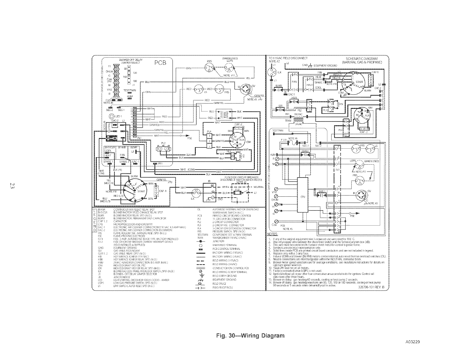
CAP 2
PL4
FS£
(cc_).
1 BIA'_R CON INLOLS [AN SEIEC RE[,£ S_sE}
B!i_,CI R BLOWERMOTORSPEEDCHANGERE[,_<SPDT
E BLWR BLOWERMOTORRE[,_< SFS__N0 i
G BIWM BIOWER_40_OR PERMANEN_Sr'Ll_CA_V_CI_OR
NE C/_' 1 2 CA_V_CI_OR!_r_ MICROPROCESSOR AND CIRCUITRY
EAC I _[ EC_RONIC AIR CI EAN_r_CONN_C_I( N_ I _ ',AC / (//:_,_ MAX i
rAC2 _[ EC_RONIC AIR CI EANERCONNECTION _COMMON_
[ _ [I A_,,_EROll OL£ S',__ b_NUAI RES_[ S_ _NC }
[ S_ [I A_,,_EPROVING E[EC_RODE
FU 1 [USE¸ 3 AMP AU_O_,_)_I','E BIA_E _'_E [ACTORy INStAllE_
FU 2 [USE OR CIRCUI_BREAKERCURREN_ IN_ERRUP_0 P,'IC_
GND _QUIP,_EN_ GROUND
GV GAS '_I_,'E REDUN_AN_
G'¢R 1 2 GAS '_1_, E RE[,_ DPS_ _N O }
I ql HO_ SUR[AC_IGNITER_115 ',AC_
I _IR HO_ SURFACEIGNITERREI,_ SPS__N O }
HUM 24',AC HU_,,II_I[IERCONNECqON {05 AMP [_V_ i
IDR INDUC_O D_V_[_ [V_)_OR RE[,_< SPS__N O _
IIK BLOWER ACCESS _N E[ IN_ER[OCK S',_I_CH SPS_ _N O }
tl BLOWER O[ [ DE[,_d ;UMPERSE[ EC_OR
_ I I(H 8_,,IIIN( DIOSE[OR SA(S (}OD_S A_, BER
L(rS I OW (AS PRESS_RESWICH S_S N 0
LS I1_,1 SW[(]H ik( 0 EES8 S_S (N C '
01 AUO RESEIN E_NAI ',,0 Oq O',ER[OAD
_EM_ERATURESWITCH_NC }
PCB PRIN_8 CIRCUI_BOARD CONtROl
P[1 /1 CIRCUI_PCBCONNECTOR
P[2 2 CIRCUI_CONNECTOR
Pb_ :_ CIRCUI_IDr,,,lEXTENSIONCONNECX)R
PRS PRESSURES',_Ci L SPS__N 0
_S_,_',_IN COMPONEN_ _ES_& PAaN_ERMINAI
;HNCqON
0 UN_4ARKE_r ER_,,IINAI
m PCBCONtROl _ERMINAI
[AC_ORY'A_RING_115'_C_
Em [IEL_ WIRING_I 1pd_C_
CONDUCX)R ON CONtROl PCB
__ HEL_'/q_ING SCRE'_ _ERMINAI
_ [IEL_D_R_HGROUND
_- EQUIPMEN_GROUND
_ _ PLUGRECEP_C[ E
[O 115VAC fIELD DISCCqNECT SCHEMATIC DIAGRAM
#2 _2 (NATURAL GAS & PROPANE)
LGNO_ £QU 'MLN1 GRO JND
_aOTES:
i arly o_th_ ong n _ equ pr_ nt wire is repac_:d use vqre r 1_d for 105 C
tJs_ onN copp{_zw re L_4w_n the, d s{x)nn_-ctsv_itch _nd _he_rn _cv urlct on box {J8)
3 ]-is VqR,n_lst be connected to urn _c_ sh_-_4t=_¢ for mt_roi to prov_ hm_
, Synt_os ree_ectr{dreprus{t_tonon[y
Solid inr_s ins&*PCB ire prnted circuit bord conductors _nd re not [nciuded n [egerld
Replace only !'_th in/p use
71 IrldUC_:r(IDV? lnd bio/'_tr (BL\_@')motors corlt in [t_vrrl [ auto res/4 thern_ i ow_ro d s/'_it/:h_s (OL)
11 F ctory corlne{:[ed "_hen LGPS is riot used
12 Iqn_tion _ockoL__1[ Occur _@erfour consecutive urlsuccessf u[ tr_4[s for igrlition Corl_ro__q!i
_[_o res_ 4"t_ _hree hours¸
326795101 REV B
Fig. 30--Wiring Diagram
A03229
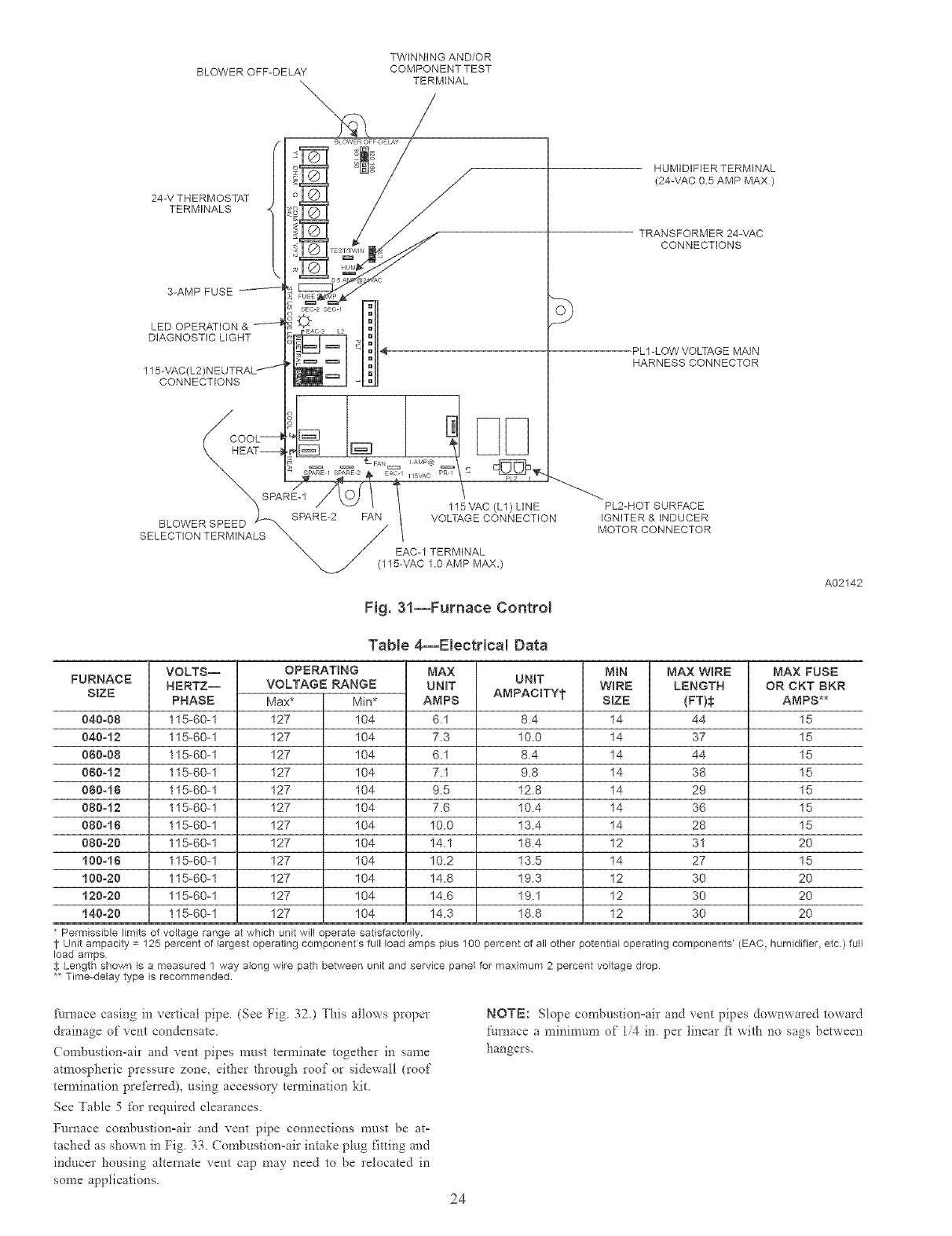
TWINNING AND/OR
BLOWER OFF-DELAY COMPONENT TEST
TERMINAL
24-V THERMOSTAT
TERMINALS
3-AMP FUSE
LED OPERATION &
DIAGNOSTIC LIGHT
115-VAC(L2)
CONNECTIONS
HUMIDIFIER TERMINAL
(24-VAC 05 AMP MAX)
TRANSFORMER 24-VAC
CONNECTIONS
PL1-LOW VOLTAGE MAIN
HARNESS CONNECTOR
Fig. 31--Furnace Control
A02142
FURNACE
SIZE
040-08
040-12
080-08
060-12
080-16
080-t2
080-16
080-20
100-16
100-20
120-20
140-20
VOLTS--
HERTZ--
PHASE
115-60-1
115-60-1
115-60-1
115-60-1
115-60-1
115-60-1
115-60-1
115-60-1
115-60-1
115-60-1
115-60-1
115-60-1
TaNe 4--Electrical Data
OPERATING
VOLTAGE RANGE
Max* Min*
127 104
127 104
127 104
127 104
127 104
127 104
127 104
127 104
127 104
127 104
127 104
127 104
MAX UNIT
UNIT
AMPS AMPACBTYt
6.1 8.4
7.3 10.0
6.1 8.4
7.1 9.8
9.5 12.8
7.6 10.4
10.0 13.4
14.1 18.4
10.2 13.5
14.8 19.3
14.6 19.1
14.3 18.8
NIN
WiRE
SIZE
14
14
14
14
14
14
14
12
14
12
12
12
MAX WiRE
LENGTH
(FT)_;
44
37
44
38
29
36
28
31
27
30
30
30
Permissible limits of voltage range at which unit will operate satisfactorily.
MAX FUSE
OR CKT BKR
AMPS**
15
15
15
15
15
15
15
20
15
20
20
20
i- Unit ampacity = 125 percent of largest operating component's full load amps plus 100 percent of all other potential operating components' (EAC, humidifier, etc ) full
load amps
$ Length shown is a measured 1 way along wire path between unit and service panel for maximum 2 percent voltage drop
** Time-delay type is recommended
_lrnace casing in vertical pipe. (See Fig 320 This allows proper
drainage of vent condensate
Combustionoair and vent pipes must terminate together in same
atmospheric pressure zone, either through roof or sidewall (roof
termination preferred), using accessoI 7 termination kit.
See Table 5 tbr required clearances.
Furnace combustion-air and xent pipe connections must be at-
tached as shown in Fig. 33. Combustion-air intake plug fitdng and
inducer housing alternate _ent cap may need to be relocated in
some applications.
NOTE: Slope combustionoair and xent pipes down\\ared toward
furnace a minimum of 14 in per linear ft with no sags between
hangers.
24
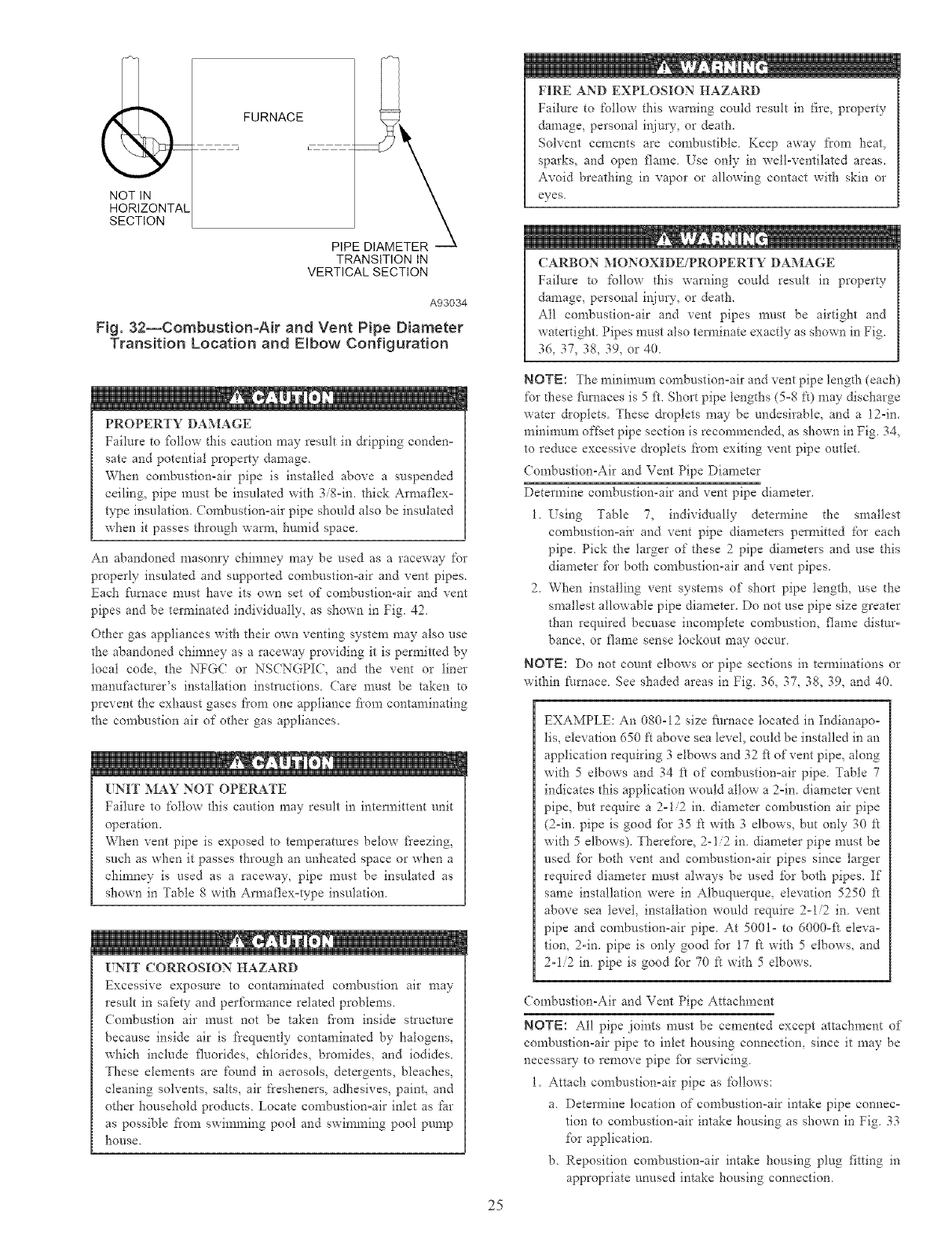
(
NOT IN
HORIZONTAL
SECTION
FURNACE
TRANSITION IN
VERTICAL SECTION
A93034
Fig. 32--CombustionoAir and Vent Pipe Diameter
Transition Location and Elbow Configuration
FIRE AND EXPLOSION HAZARD
Failure to follow this warning could result in fire, property
damage, personal injury, or death.
Solvent cements are combustible. Keep away h'om heat,
sparks, and open flame. Use only in well-ventilated areas.
Avoid breathing in vapor or allowing contact with skin or
eyes.
CARBON MONOXIDE/PROPERTY DAMAGE
Failure to follow this warning could result in property
damage, personal injury, or death.
All combustion-air and vent pipes must be airtight and
watertight Pipes must also tem_inate exactly as shown in Fig.
36, 37, 38, 39, or 40.
PROPERTY DAMAGE
Failure to %llow this caution may result in dripping condeno
sate and potential property damage.
When combustion-air pipe is installed above a suspended
ceiling, pipe must be insulated with 3/8oin. thick Armaflexo
type insulation. ( ombustionoair pipe should also be insulated
when it passes through wam_, humid space
An abandoned masonry chimney may be used as a raceway %r
properly insulated and supported combustionoair and vent pipes.
Eacia fhrnace must have its own set of combustion-air and vent
pipes and be terminated individually, as shown in Fig. 42.
Other gas appliances with their own venting system may also use
the abandoned chimney as a raceway providing it is permitted by
local code, the NFGC or NSCNGPIC, and the vent or liner
manufacturer's installation instn/ctions (?are must be taken to
prevent the exhaust gases ti'om one appliance fiom contaminating
the combustion air of other gas appliances.
UNIT MAY NOT OPERATE
Failure to follow this caution may result in intem_ittent unit
operation.
When vent pipe is exposed to temperatures below fi'eezing,
such as when it passes through an unheated space or when a
chimney is used as a raceway, pipe must be insulated as
shown in Table 8 with Armaflexotype insulation
UNIT CORROSION HAZARD
Excessive exposure to contaminated comhustion air may
result in sa_bty and perfbrrnance related problems.
Combustion air must not be taken fiom inside structure
because inside air is frequently contaminated by halogens,
which include fluorides, chlorides, bromides, and iodides.
These elements are found in aerosols, detergents, bleaches,
cleaning solvents, salts, air fi'esheners, adhesives, paint, and
other household products. Locate combustionoair inlet as _r
as possible fi'om swimming pool and swimming pool pump
hol.lSe,
NOTE: The minimum combustionoair and vent pipe length (each)
for d-_ese hlmaces is 5 ft. Short pipe lengths (5°8 ft) may discharge
water droplets These &oplets may be undesirable, and a 12-in.
minimum off'set pipe section is recommended, as shown in Fig. 34,
to reduce excessive droplets f_'om exiting vent pipe outlet.
Combustion-Air and Vent Pipe Diameter
Determine combustion-air and vent pipe diameter.
1. Using Table 7, individually determine the smallest
combustionoair and vent pipe diameters permitted for each
pipe. Pick the larger of these 2pipe diameters and use this
diameter for both combustionoair and vent pipes.
2. When installing vent systems of short pipe length, use the
smallest allowable pipe diameter. Do not use pipe size greater
than required becuase incomplete combustion, flame distur-
bance, or flame sense lockout may occur.
NOTE: Do not count elbows or pipe sections in terminations or
within h_mace. See shaded areas in Fig. 36, 37, 38, 39, and 40.
EXAMPLE: An 080-12 size _hrnace located in Indianapo-
lis, elevation 650 ft above sea level, could be installed in an
application requiring 3 elbows and 32 ft of vent pipe, along
with 5 elbows and 34 ft of cornhustionoair pipe Table 7
indicates this application wo_dd allow a 2oin. diameter vent
pipe, but require a 2ol/2 in diameter combustion air pipe
(2oin. pipe is good fbr 35 ft with 3 elbows, but only 30 ft
with 5 elbows). Therelbre, 2-1/2 in diameter pipe must be
used for both vent and combustion-air pipes since larger
required diameter must always be used for both pipes. If
same installation were in Albuquerque, elevation 5250 _
above sea level, installation would require 2ol/2 in. vent
pipe and combustion-air pipe. At 5001o to 6000o_t eleva-
tion, 2-in. pipe is only good for 17 R with 5 elbows, and
2-1/2 in. pipe is good fbr 70 R with 5 elbows.
(ombustion-Air and Vent Pipe Attachment
NOTE: All pipe joints must be cemented except attachment of
combustion-air pipe to inlet housing connection, since it may be
necessary to remove pipe _br servicing.
1. Attach combustion=air pipe as follows:
a. Determine location of combustion-air intake pipe connec-
tion to combustion-air intake housing as shown in Fig. 33
for application.
b. Reposition combustionoair intake housing plug fitting in
appropriate unused intake housing connection.
25
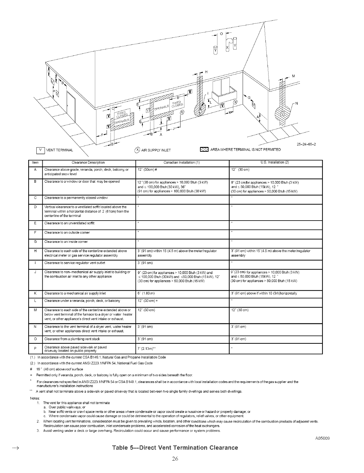
i_>
VENTTERMINAL (_) AIR SUPPLY iNLET AREA WHERE TERMINAL IS NOT PERMITED
Item Clearance Description
A Clearance above grade, veranda, porch, deck, balcony, or
anticipated snow level
B Clearance to a window or door that may be opened
C Clearance to a permanently closed window
D Ver ficaI clearance to a ventilated soffit located above the
terminal within a horizontal distance of 2 (61bm) from the
centedine of the terminal
E Clearance to an unventilated soffit
F Clearance 1oan outside corner
G Clearance to an inside corner
H Clearance to each side of the centedine extended above
electrical meter or gas service regulator assembly
I Clearance to service regulator vent outlet
J Clearance to non-mechanical air supply inlet to building or
the combustion air inlet to any other appliance
K Clearance to a mechanical air supply inlet
L Clearance under a veranda, porch, deck, or balcony
M Clearance to each side of the centeriine extended above or
below vent terminal of the furnace to a dryer or water heater
vent, or other appliance's direct vent intake or exhaust
N Clearance to the vent terminal of a dryer vent. water heater
vent, or other appliances direct vent intake or exhaust
O Clearance from a plumbing vent stack
p Clearance above paved sidewalk or paved
driveway located on public property
(I) In accordance with the current CSA B149 1. Natural Gas and Pro
Canadian Installation (1)
12" (30cm) #
12 "(30 cm) for appliances > 10,OO0Btuh (3 kW)
and < 100,000 Btuh(30 kW), 36"
(91 cm) for appliances > 100.000 Btuh (30 kW)
3" (91 cm) within 15 (4:5 m) above the meter/regulator
assembly
3" (91 cm)
9" (23 cm)_r appliances > 10,000 Btuh (3 kW) and
< 100,000 Btuh (30kW) and <50.000 Btuh (15 kW), 12"
(30 cm) for appliances > 50,000 Btuh (15 kW)
6" (I 83m)
12" (30 cm) +
12" (30 cm)
3" (91 cm)
3" (91 cm)
T(2 13m)**
,ane Installafion Code
US Installation (2)
12" (30 cm)
9" (23 cmyor appliances > 10,000 Btuh (3 kW)
and < 50,000 Btuh (15kW), 12 "
(30 cm) for appJiances > 50,000 Btuh (15 kW)
3' (91 cm) within 15"(45 m) above the meter/regulator
assembly
9"(23 cm) for appliances > 10,000 Btuh (3 kW)
and < 50.000 Btuh (15kW), 12 "
(30 cm) for appliances > 50,000 Btuh (15 kW)
3' (91 cm) above ifvwthin 10 (3rh)horizontally
12" (30 cm)
3' (91 cm)
3' (91 cm)
(2) In accordance with the current ANSI Z223 1/NFPA 54, Nafional Fuel Gas Code
# 18" (46cm)aboveroofsurface
+ Permitted only if veranda, porch, deck, or balcony is fully open on a minimum of two sides beneath the floor
For clearances not specified in ANSI Z223.1/N FPA 54or CSA B 149 1, clearances shall be in accordance with local instailafion codes and the requirements of the gas supplier and the
manufacturer's installation instructions
** A vent shall not terminate above a sidewalk or paved driveway that is located between two single family dwellings and serves both dwellings
Notes:
1 The vent for this appliance shall not terminate
a. Over public walkways; or
b Near soffit vents or crawl space vents or other areas where condensate or vapor could create a nusaince or hazard or property damage; or
c. Where condensate vapor could cause damage or could be detrimental to the operation of regulators, relief valves, or other equipment.
2 When locating vent terminations, consideration must be given to prevailing winds, location, and other conditions which may cause recirculafion of the combustion products of adjacent vents
Recirculation can cause poor combustion, inlet condensate problems, and accelerated corrosion of the heat exchangers
3 Avoid venting under a deck or large overhang Recircula0on could occur and cause performance or system problems
A05009
Table 5--Direct Vent Termination Clearance
26
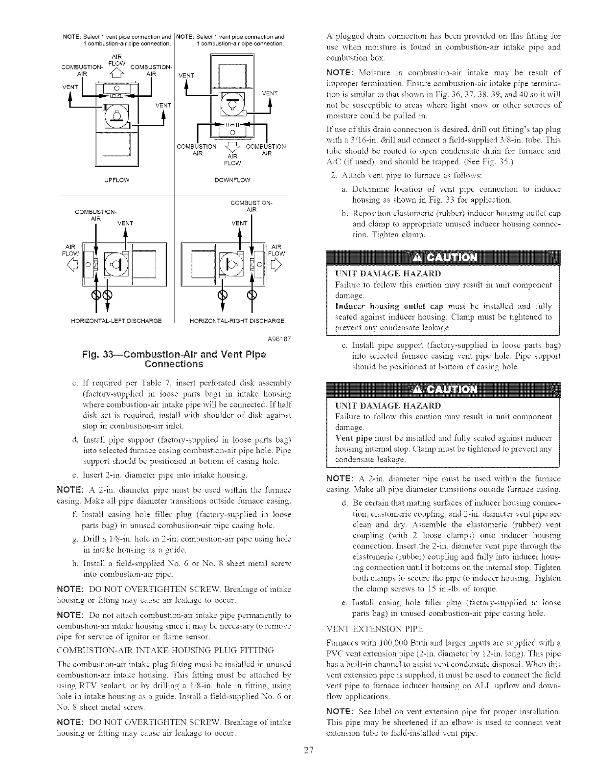
NOTE: Select 1 vent pipe connection and
1 combustion-air pipe connection.
AIR
COMBUSTION-AIR _ COMBUSTION-AIR
UPFLOW
COMBUSTION-
AIR VENT
HORIZONTAL-LEFT DISCHARGE
NOTE: Select 1 vent pipe connection and
1 combustion-air pipe connection.
COMBUSTION- _ COMBUSTION-
AIR AIR
AIR
FLOW
DOWNFLOW
COMBUSTION-
AiR
VENT
HORIZONTAL-RIGHT DISCHARGE
A96187
Fig. 33--Combustion-Air and Vent Pipe
Connections
c. If required per Table 7, insert per%rated disk assembly
(factow_supplied in loose parts bag) in intake housing
where combustion-air intake pipe wilt be connected If half
disk set is require& install with shoulder of disk against
stop in combustionoair inlet
d. Install pipe support (fi_ctoryosupplied in loose parts bag)
into selected fi/mace casing combustion-air pipe hole. Pipe
support should be positioned at bottom of casing hole.
e. Insert 2-in. diameter pipe into intake housing.
NOTE: A 2oin. diameter pipe rmtst be used within the Nmace
casing. Make all pipe diameter transitions outside I:mnace casing.
_ Instal! casing hole tiller plug ([i_ctow-supplied in loose
parts bag) in unused congbustionoair pipe casing hole.
g. Drill a 1/8-in. hole in 2-in. combustion-air pipe using hole
in intake housing as a guide.
h. Install a fieldosupplied No. 6 or No. g sheet metal screw
into combustionoair pipe.
NOTE: DO NOT OVERTIGHTEN SCREW. Breakage of intake
housing or fitting may cause air leakage to occur.
NOTE: Do not attach combustion-air intake pipe permanently to
combustionoair intake housing since it may be necessary- to remove
pipe for service of ignitor or flame sensor.
COMBUSTIONoAIR INTAKE HOUSING PLUG FITTING
The combustion-air intake plug fitting must be installed in unused
combustion-air intake housing. This fitting must be attached by
using RTV sealant, or by &illing a l/g-in, hole in fitting, using
hole in intake housing as a guide. Install a _ield-supplied No. 6 or
No. 8 sheet metal screw.
NOTE: DO NOT OVERTIGHTEN SCREW. Breakage of intake
housing or fitting may cause air leakage to occur
27
A plugged drain connection has been provided on this fitting for
use _hen moisture is found in combustion-air intake pipe and
combustion box.
NOTE: Moisture in cornbustionoair intake may be result of
improper termination. Ensure combustion-air intake pipe termina-
tion is similar to that shown in Fig. 36, 37, 38, 39, and 40 so it will
not be susceptible to areas where light snow or other sources of
moisture could be pulled in.
If use of this drain connection is desire& drill out fitting's tap plug
with a 3/16-in. &ill and connect a field-supplied 3/8-in. tube. This
robe should be routed to open condensate drain for ft_rnace and
AiC (if used), and should be trapped. (See Fig. 35.)
2. Attach vent pipe to ft_rnace as follows:
a. Determine location of vent pipe connection to inducer
housing as shown in Fig. 33 for application.
b. Reposition elastomeric (robber) inducer housing outlet cap
and clamp to appropriate unused inducer housing connec_
don. Tighten clamp.
INIT DAMAGE HAZARD
Failure to follow this caution may result in unit component
damage
Inducer housing outle_ cap must be installed and fktlly
seated against inducer housing. (lamp must be tightened to
prevent any condensate leakage.
c Install pipe support (_i_ctoryosupplied in loose parts bag)
into selected ftmaace casing vent pipe hole. Pipe support
should be positioned at bottom of casing hole
_:l 0-_ '_
INleT DAMAGE HAZARD
Failure to %llow this caution may result in unit component
damage
Vent pipe must be installed and fi/lly seated against inducer
housing internal stop. Clamp must be tightened to prevent any
condensate leakage.
NOTE: A 2-in. diameter pipe must be used within the furnace
casing. Make all pipe diameter transitions outside [:tmaace casing.
d Be certain that mating surfaces of inducer housing connec-
tion, elastomeric coupling, and 2oin diameter vent pipe are
clean and dw Assemble the elastomeric (l_./bber) vent
coupling (with 2loose clamps) onto inducer housing
connection Insert the 2oin diameter vent pipe through the
elastomeric (rubber) coupling and _ally into inducer hous-
ing connection until it bottoms on the internal stop Tighten
both clamps to secure the pipe to inducer housing Tighten
the clamp screws to 15 in olb. of torque.
e Install casing hole filler plug di_ctoryosupplied in loose
parts bag) in unused combustion-air pipe casing hole.
VENT EXTENSION PIPE
Furnaces with 100,000 Btuh and larger inputs are supplied with a
PVC vent extension pipe (2oin. diameter by 12oin long). This pipe
has a built-in channel to assist vent condensate disposal When this
vent extension pipe is supplied, it must be used to connect the field
vent pipe to _arnace inducer housing on ALL upflow and down-
flow applications
NOTE: See label on vent extension pipe *;or proper installation.
This pipe may be shortened if an elbow is used to connect vent
extension robe to fieldoinstalled vent pipe.
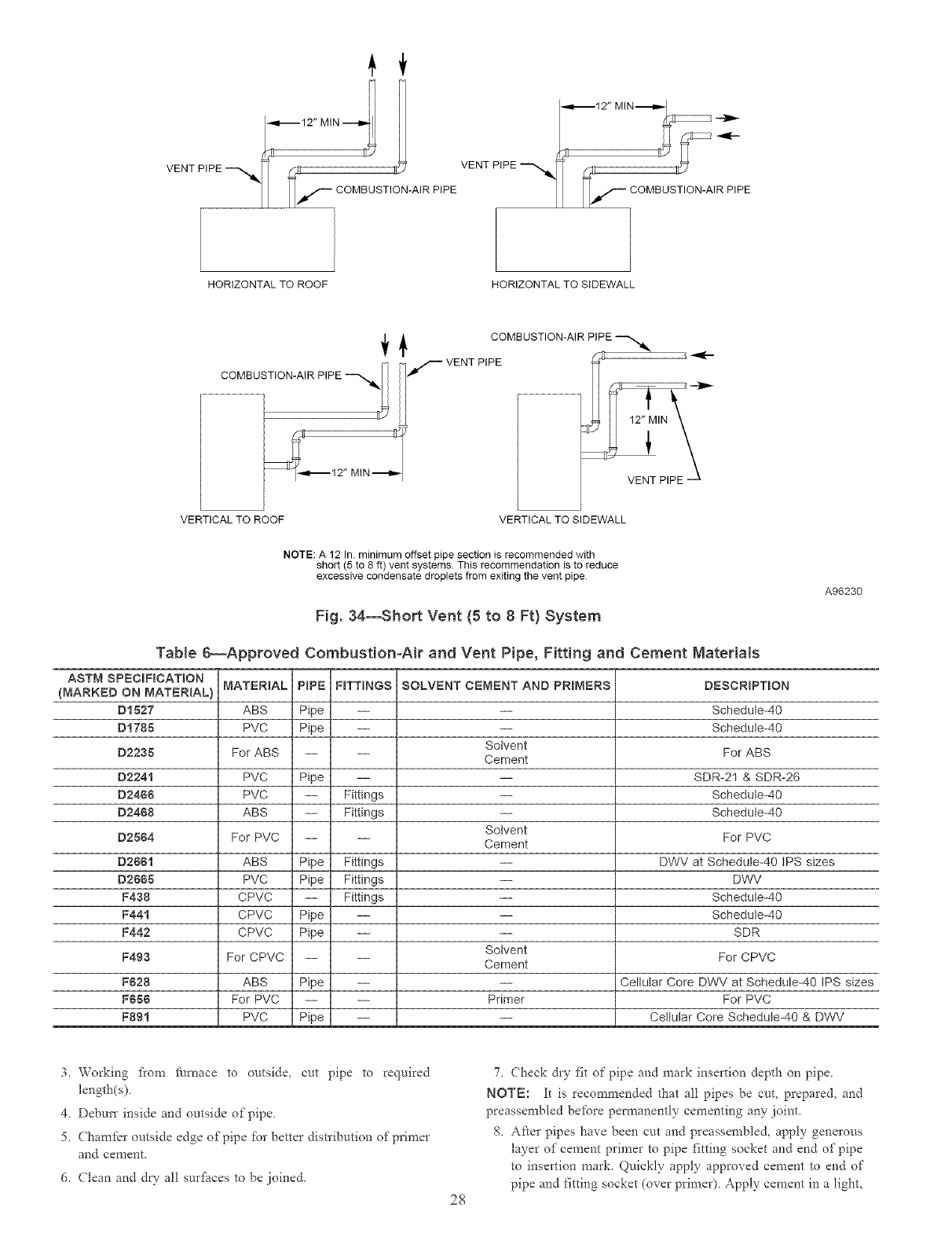
HORIZONTAL TO ROOF
--,,I.-- 12" MIN---,,-- I
I 4
VENTP,PE--
l_lt/'-- CO MBUSTION-AIR PIPE
HORIZONTALTO SIDEWALL
COMBUSTION-AIR PIPE --""_"I
MIN ,_m,,-
COMBUSTION-AIR PiPE
/-- VENT PiPE
VERTICAL TO ROOF VERTICAL TO SIDEWALL
NOTE: A 12 In. minimum offset pipe section is recommended with
short (5 to 8 ft) vent systems. This recommendation is to reduce
excessive condensate droplets from exiting the vent pipe
Fig. 34--Short Vent {5 to 8 Ft) System
A96230
TaNe 6--Approved Combustion-Air and Vent Pipe,Fitting and Cement Materials
ASTM SPECIFICATION
(MARKED ON MATER_AL)
D1527
D1785
D2235
D2241
D2488
D2488
D2564
D2661
D2885
MATERIAL PiPE FITTINGS
ABS Pipe --
PVC Pipe --
For ABS -- --
PVC Pipe --
PVC -- Fittings
ABS -- Fittings
For PVC -- --
ABS Pipe Fittings
PVC Pipe Fittings
SOLVENT CEMENT AND PRBMERS
Solvent
Cement
Sotvent
Cement
DESCRIPTBON
Schedule-40
Schedule-40
For ABS
SDR-21 & SDR-26
Schedule-40
Schedule-40
For PVC
DWV at Schedule-40 tPS sizes
DWV
F438
F441
F442
F493
F628
F856
F891
CPVC -- Fittings
CPVC Pipe --
CPVC Pipe --
For CPVC -- --
ABS Pipe --
For PVC -- --
PVC Pipe --
Solvent
Cement
Primer
Schedule-40
Schedule-40
SDR
For CPVC
Cellular Core DWV at Schedule-40 IPS sizes
For PVC
Ceitular Core Schedule-40 & DWV
3_ Working fiom ft_rnace to outside, cut pipe to required
length(s)_
4. Deburr inside and outside of pipe
5. (hamlet outside edge of pipe for better distribution of primer
and cement
6. (lean and d_ all sur_i_ces to be joined.
28
7. (beck &y fit of pipe and mark insertion depth on pipe
NOTE: It is recommended that all pipes be cut, prepared, and
preassembled be_bre pem_anently cementing any joint.
8. ARer pipes have been cut and preassembled, apply generous
layer of cement primer to pipe fitting socket and end of pipe
to insertion mark. Quickly apply approved cement to end of
pipe and fitting socket (over primer). Apply cement in a light,
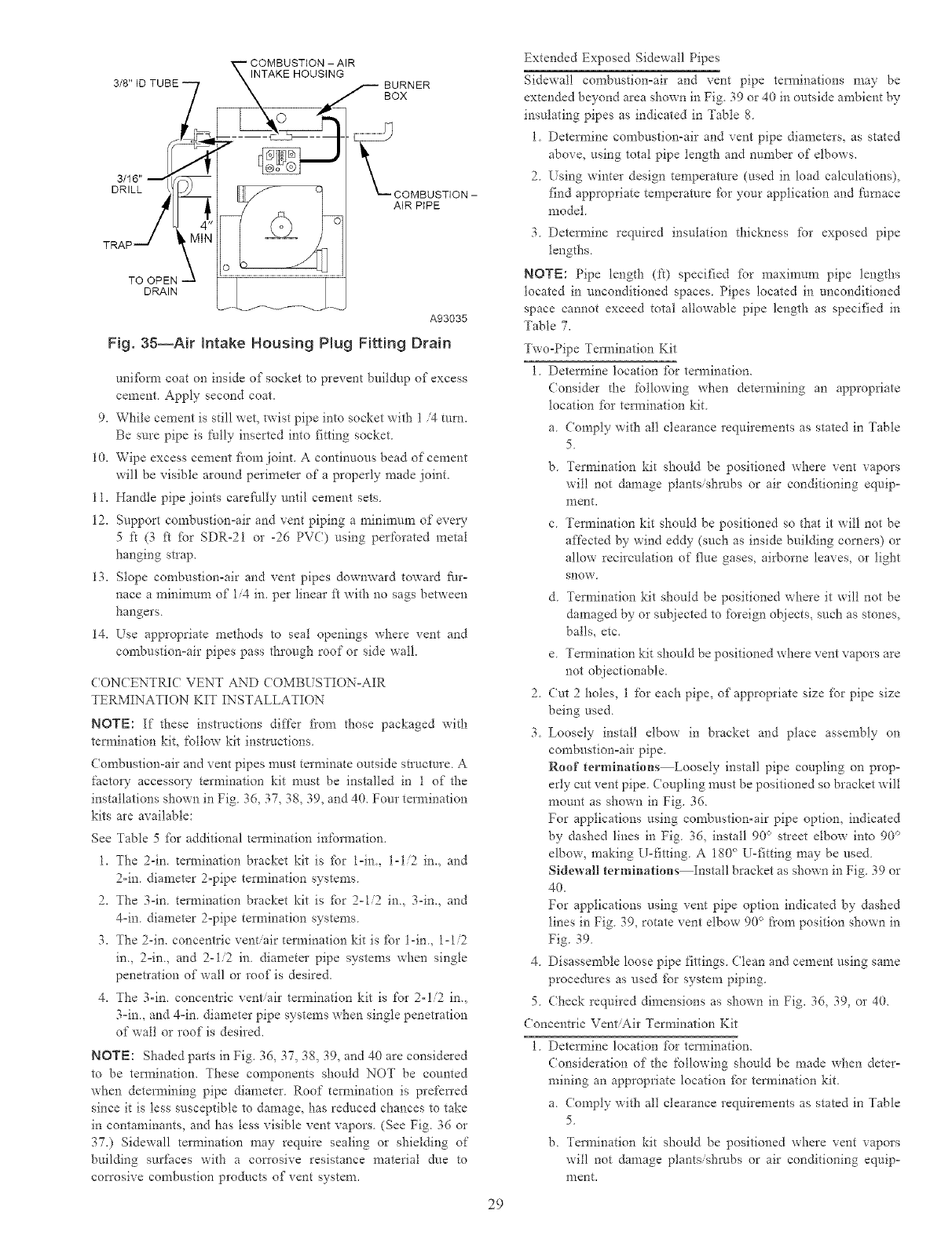
COMBUSTION - AIR
INTAKE HOUSING
BURNER
BOX
DRILL
TO OPEN
DRAIN
L_COMBUSTION -
AIR PIPE
A93035
Fig. 35--Air intake Housing Plug Fitting Drain
unifbrm coat on inside of socket to prevent buildup of excess
cement Apply second coat.
9. While cement is still wet, twist pipe into socket with 1/4 turn.
Be s-are pipe is/_ully inserted into fitting socket
10. Wipe excess cement fi'om joint. A continuous bead of cement
will be visible around perimeter of a properly made joint.
11. Handle pipe joints careNlly until cement sets.
12. Support combustion-air and vent piping a minimum of eve_
5 fi (3 ft for SDR-21 or -26 PVC) using perforated metal
hanging stlap.
13. Slope combustion-air and vent pipes downward toward Nr-
nace a n_inimum of 1/4 in. per linear ft with no sags between
hangers.
14. Use appropriate methods to seal openings where vent and
combustion-air pipes pass through roof or side wall.
(ONCENTRIC VENT AND (OMBUSTION-AIR
TERMINATION KIT INSTALLATION
NOTE: If these instructions differ fi'om those packaged with
termination kit, follow kit instructions
Combustion-air and vent pipes must terminate outside structure A
factory accessory termination kit must be installed in 1 of the
installations shown in Fig 36, 37, 38, 39, and 40. Four termination
kits are available:
See Table 5 fPr additional termination inf'ormation.
1. The 2-in. [ermination bracket kit is fbr 1-in, 1-1/2 in. and
2-in. diameter 2-pipe termination systems.
2. The 3-in. termination bracket kit is fbr 2ol/2 in., 3-in., and
4-in. diameter 2-pipe termination systems.
3. The 2-in. concentric vent/air termination kit is for l-in. 1-1/2
in., 2-in., and 2-1/2 in. diameter pipe systems when single
penetration of wall or roof is desired.
4. The 3-in. concenkic vent/air tei_nination kit is for 2-1/2 in.,
3-in. and 4-in. diameter pipe systems when single penet*ation
of wall or roof is desired.
NOTE: Shaded parts in Fig. 36, 37, 38, 39, and 40 are considered
to be tem_ination. These components should NOT be counted
when determining pipe diameter Roof termination is prefen'ed
since it is less susceptible to damage, has reduced chances to take
in contaminants, and has tess visible vent vapors (See Fig. 36 or
37.) Sidewall termination may require sealing or shielding of
building surfaces with a con'osive resistance material due to
corrosive combustion products of vent system.
29
Extended Exposed Sidewall Pipes
Sidewall congbustion°air and vent pipe tem_inations may be
extended beyond area shown in Fig 39 or 40 in outside ambient by
insulating pipes as indicated in Table 8
1 Determine combustion-air and vent pipe diameters, as stated
above, using total pipe length and number of elbows.
2 [sing winter design temperatme (used in load calculations),
find appropriate temperature for your application and furaace
model
3 Detem_ine required insulation thickness for exposed pipe
lengths
NOTE: Pipe length (k) specified _br maximum pipe lengths
tocated in unconditioned spaces Pipes located in unconditioned
space cannot exceed total allowable pipe length as specified in
Table 7.
Two-Pipe Tem_ination Kit
1 Determine location _br tem_ination.
(onside* the following when determining an appropriate
location _br tem_ination kit
a Compty with all clearance requirements as stated in Table
5
b Termination kit should be positioned where vent vapors
wil! not damage plants/shrubs or air conditioning equip-
ment.
c. Teimination kit should be positioned so that it will not be
affected by wind eddy (such as inside building corners) or
allow recirculation of flue gases, airborne leaves, or light
snow
d Tem_ination kit should be positioned where it will not be
damaged by or subjected to foreign objects_ such as stones,
balls, etc.
e. Teimination kit should be positioned where vent vapors are
not objectionable.
2. Cut 2holes, 1 for each pipe, of appropriate size for pipe size
being used.
3. Loosely install elbow in bracket and place assembly on
combustion=air pipe.
Roof terminations Loosely install pipe coupling on prop-
erly cut vent pipe. Coupling must be positioned so bracket will
mount as shown in Fig. 36.
For applications using comhustion-air pipe option, indicated
by dashed lines in Fig. 36, install 90 ° street elbow into 90 °
elbow, making U-fitting. A 180 _>U-fitting may be used.
Sidewall terminations Install bracket as shown in Fig. 39 or
40.
For applications using vent pipe option indicated by dashed
lines in Fig. 39, rotate vent elbow 90 _ from position shown in
Fig. 39.
4. Disassemble loose pipe fittings. Clean and cement using same
procedures as used fPr system piping.
5. (heck required dimensions as shown in Fig. 36, 39, or 40.
Concentric Vent/Air Termination Kit
1. Determine location fbr termination.
(onsideration of the following should be made when deter-
mining an appropriate location fbr tem_ination kit.
a. Comply with all clearance requirements as stated in Table
5.
b. Tem_ination kit should be positioned where vent vapors
will not damage ptantsishrnbs or air conditioning equip-
nlent,
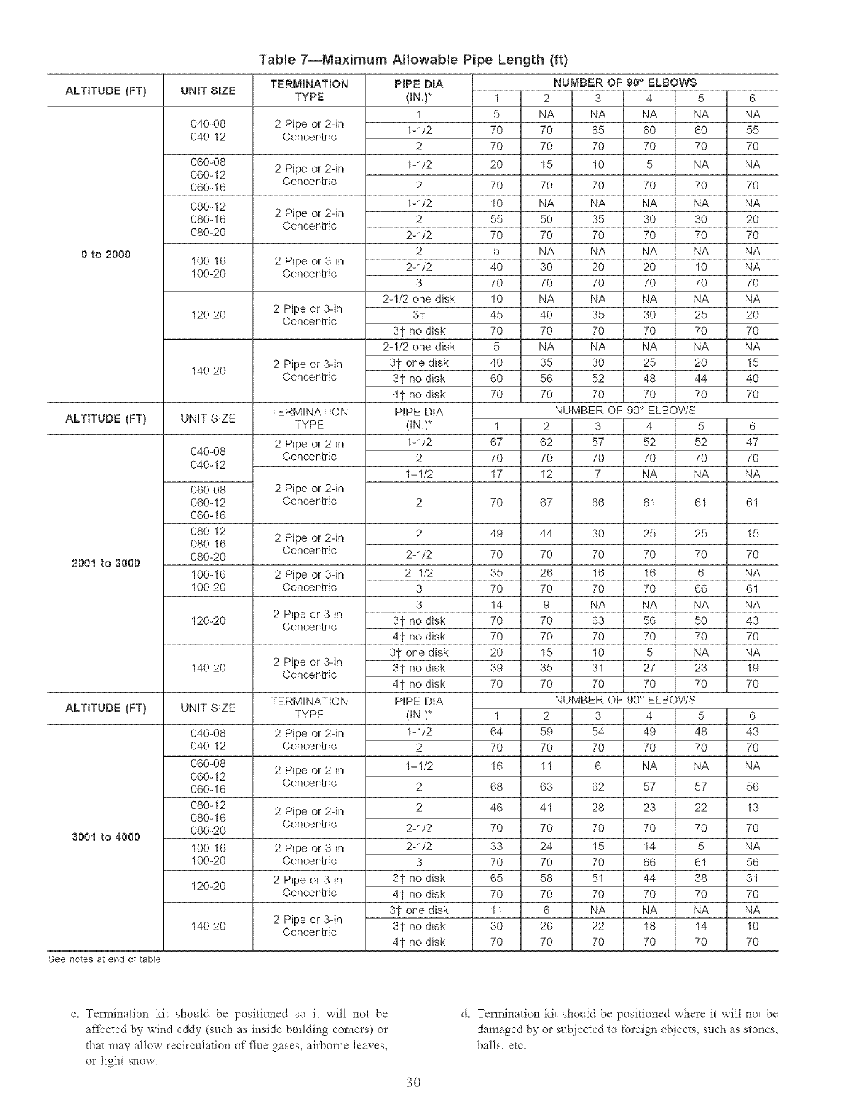
ALTITUDE (FT)
0 to 2000
ALTITUDE (FT)
2001 to 3000
ALTITUDE (FT)
3001 to 4000
See notes at end of tame
Tab{e 7--Maximum Allowable Pipe Length (ft)
UNIT SBZE
040-08
040-12
060-08
060-12
060-16
080-12
080-16
080-20
100-16
100-20
120-20
140-20
UNIT SIZE
040-08
040-12
060-08
060-12
060-16
080-12
080-16
080-20
100-16
100-20
120-20
140-20
UNIT SIZE
040-08
040-12
060-08
060-12
060-16
080-12
080-16
080-20
100-16
100-20
120-20
140-20
TERMINATION
TYPE
2 Pipe or 2-in
Concentric
2 Pipe or 2-in
Concentric
2 Pipe or 2-in
Concentric
2 Pipe or 3-in
Concentric
2 Pipe or 3-in.
Concentric
2 Pipe or 3-in.
Concentric
TERMINATION
TYPE
2 Pipe or 2-in
Concentric
2 Pipe or 2-in
Concentric
2 Pipe or 2-in
Concentric
2 Pipe or 3-in
Concentric
2 Pipe or 3-in.
Concentric
2 Pipe or 3-in.
Concentric
TERMINATION
TYPE
2 Pipe or 2-in
Concentric
2 Pipe or 2-in
Concentric
2 Pipe or 2-in
Concentric
2 Pipe or 3-in
Concentric
2 Pipe or 3-in.
Concentric
2 Pipe or 3-in.
Concentric
PIPE OmA
{IN,)*
1
1-1/2
2
1-1/2
2
1-1/2
2
2-1/2
2
2-1/2
3
2-1/2 one disk
31
3t no disk
2-1/2 one disk
3t one disk
3? no disk
41-no disk
PIPE DIA
(IN.)*
1-1/2
2
1-1/2
2-1/2
2-1/2
3
3
3? no disk
41-no disk
3? one disk
3? no disk
4? no disk
PIPE DtA
(IN.)*
1-1/2
2
1-1/2
2
2-1/2
2-1/2
3
3? no disk
41-no disk
3? one disk
3? no disk
4t no disk
NUMBER OF 90 ° ELBOWS
1 2 3 4 5 6
5 NA NA NA NA NA
70 70 65 60 60 55
70 70 70 70 70 70
20 15 10 5 NA NA
70 70 70 70 70 70
10 NA NA NA NA NA
55 50 35 30 30 20
70 70 70 70 70 70
5 NA NA NA NA NA
40 30 20 20 10 NA
70 70 70 70 70 70
10 NA NA NA NA NA
45 40 35 30 25 20
70 70 70 70 70 70
5 NA NA NA NA NA
40 35 30 25 20 15
60 56 52 48 44 40
70 70 70 70 70 70
NUMBER OF 90 ° ELBOWS
1 2 3 4 5 6
67 62 57 52 52 47
70 70 70 70 70 70
17 12 7 NA NA NA
70 67 66 61 61 61
40
7O
35
7O
14
7O
7O
2O
30
7O
44
7O
26
7O
9
7O
7O
15
35
7O
1 2
64 59
70 70
16 11
68 63
46 41
70 70
33 24
70 70
65 58
70 70
11 6
30 26
70 70
30
70
16
70
NA
63
70
10
31
70
NUMBER
3
54
70
6
62
25 25 15
70 70 70
16 6 NA
70 66 61
NA NA NA
56 50 43
70 70 70
5 NA NA
27 23 19
70 70 70
OF 90 ° ELBOWS
4 5 6
49 48 43
70 70 70
NA NA NA
57 57 56
28 23 22 13
70 70 70 70
15 14 5 NA
70 66 61 56
51 44 38 31
70 70 70 70
NA NA NA NA
22 18 14 10
70 70 70 70
c, Tem_ination kit should be positioned so it will not be
a_:_cted by wind eddy (such as inside building comers) or
that may allow recirculation of flue gases, airborne leaves,
or light snow,
3O
d, Tem_ination kit should be positioned where it will not be
damaged by or subjected to foreign objects, such as stones,
balls, etc,
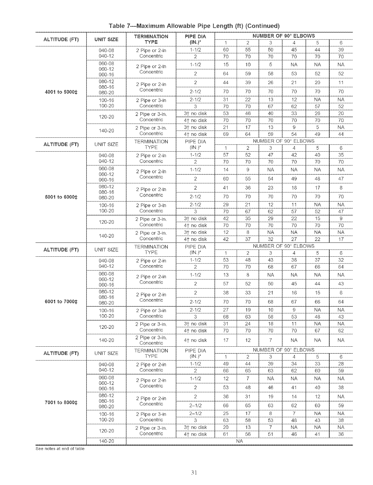
ALTITUDE (FT)
4001 to 5000_
ALTITUDE (FT)
5001 to 6000_
ALTITUDE (FT)
8001 to 7000_
ALTITUDE (FT)
7001 to 8000_
See notes at end of table
Table 7--Maximum AHowable Pipe Length (ft) (Continued)
UNIT SiZE
040-08
040-12
060-08
060-12
060-16
080-12
080-16
080-20
100-16
100-20
120-20
140-20
UNIT SiZE
040-08
040-12
060-08
060-12
060-16
080-12
080-16
080-20
100-16
100-20
120-20
140-20
UNIT SiZE
040-08
040-12
060-08
060-12
060-16
080-12
080-16
080-20
100-16
100-20
120-20
140-20
UNIT SiZE
040-08
040-12
060-08
060-12
060-16
080-12
080-16
080-20
100-16
100-20
120-20
140-20
TERMINATION
TYPE
2 Pipe or 2-in
Concentric
2 Pipe or 2-in
Concentric
2 Pipe or 2-in
Concentric
2 Pipe or 3-in
Concentric
2 Pipe or 3-in.
Concentric
2 Pipe or 3dn.
Concentric
TERMINATION
TYPE
2 Pipe or 2-in
Concentric
2 Pipe or 2-in
Concentric
2 Pipe or 2-in
Concentric
2 Pipe or 3-in
Concentric
2 Pipe or 3-in.
Concentric
2 Pipe or 3dn.
Concentric
TERMiNATiON
TYPE
2 Pipe or 2-in
Concentric
2 Pipe or 2-in
Concentric
2 Pipe or 2-in
Concentric
2 Pipe or 3-in
Concentric
2 Pipe or 3dn.
Concentric
2 Pipe or 3dn.
Concentric
TERMINATION
TYPE
2 Pipe or 2-in
Concentric
2 Pipe or 2-in
Concentric
2 Pipe or 2-in
Concentric
2 Pipe or 3-in
Concentric
2 Pipe or 3-in.
Concentric
PIPE DmA
(IN,)*
1-1/2
2
1-1/2
2
2
2-1/2
2-1/2
3
3t no disk
41 no disk
3t no disk
4t no disk
PIPE DtA
dN.)*
1-1/2
2
1-1/2
2
2
2-1/2
2-1/2
3
3t no disk
41 no disk
3t no disk
4t no disk
PIPE DtA
dN.)*
1-1/2
2
1-1/2
2
2
2-1/2
2-1/2
3
3t no disk
4t no disk
4t no disk
PIPE DIA
(IN.)*
1-1/2
2
1-1/2
2
2
2-1/2
2-1/2
3
3t no disk
4t no disk
NUMBER OF g0 ° ELBOWS
1 2 3 4 5
60 55 50 45 44
70 70 70 70 70
15 10 5 NA NA
64 59 58 53 52
44 39 26 21 20
70 70 70 70 70
31 22 13 12 NA
70 70 67 62 57
53 46 40 33 26
70 70 70 70 70
21 17 13 9 5
69 64 59 54 49
NUMBER OF 90 ° ELBOWS
1 2 3 4 5
57 52 47 42 40
70 70 70 70 70
14 9 NA NA NA
60 55 54 49 48
41 36 23 18 17
70 70 70 70 70
29 21 12 11 NA
70 67 62 57 52
42 35 29 22 15
70 70 70 70 70
12 8 NA NA NA
42 37 32 27 22
NUMBER OF 90 ° ELBOWS
1 2 3 4 5
53 48 43 38 37
70 70 68 67 66
13 8 NA NA NA
57 52 50 45 44
38 33 21 16 15
70 70 68 67 66
27 19 10 9 NA
68 63 58 53 48
31 24 18 11 NA
70 70 70 70 67
17 12 7 NA NA
NUMBER OF 90 ° ELBOWS
1 2 3 4 5
49 44 39 34 33
66 65 63 62 60
12 7 NA NA NA
53 48 46 41 40
36 31 19 14 12
66 65 63 62 60
25 17 8 7 NA
63 58 53 48 43
20 13 7 NA NA
61 56 51 46 41
NA
6
39
7O
NA
52
11
7O
NA
52
2O
7O
NA
44
6
35
7O
NA
47
8
7O
NA
47
g
7O
NA
17
6
32
64
NA
43
6
64
NA
43
NA
62
NA
6
28
59
NA
38
NA
59
NA
38
NA
36
31
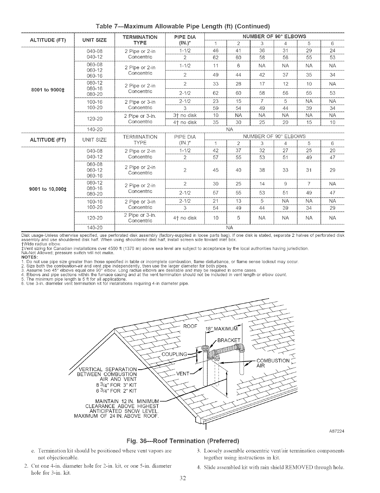
TaNe7--Maximum Allowable Pipe Length (ft) (Continued)
ALTITUDE (FT}
800t to 9000@
ALTITUDE (FT)
9001 to I0,000_
UNiT SBZE
040-08
040-I2
060-08
060-12
060-16
080-I2
080-16
080-20
100-16
100-20
120-20
140-20
UNIT SIZE
040-08
040-12
060-08
060-12
060-16
080-12
080-16
080-20
100-16
100-20
120-20
140-20
TERMINATBON
TYPE
2 Pipe or 2-in
Concentric
2 Pipe or 2-in
Concentric
2 Pipe or 2-in
Concentric
2 Pipe or 3-in
Concentric
2 Pipe or 3-in.
Concentric
TERMINATION
TYPE
2 Pipe or 2-in
Concentric
2 Pipe or 2-in
Concentric
2 Pipe or 2-in
Concentric
2 Pipe or 3-in
Concentric
2 Pipe or 3-in.
Concentric
PIPE DmA NUMBER OF 90 ° ELBOWS
(IN.)* 1 2 3 4 5 6
1-1/2 46 41 36 31 29 24
2 62 60 58 56 55 53
1-1/2 11 6 NA NA NA NA
2 49 44 42 37 35 34
2 33 28 17 12 10 NA
2-1/2 62 60 58 56 55 53
2-1/2 23 15 7 5 NA NA
3 59 54 49 44 39 34
31- no disk 10 NA NA NA NA NA
41- no disk 35 30 25 20 15 10
NA
PiPE DtA NUMBER OF 90 ° ELBOWS
(IN.)* 1 2 3 4 5
1-1/2 42 37 32 27 25
2 57 55 53 51 49
6
2O
47
45 40 38 33 31 29
2 30 25 14 9 7 NA
2-1/2 57 55 53 51 49 47
2-1/2 21 13 5 NA NA NA
3 54 49 44 39 34 29
4t no disk 10 5 NA NA NA NA
NA
Disk usage-Unless otherwise specified, use perforated disk assembly (factory-supplied in loose parts bag). If one disk is stated, separate 2 halves of perforated disk
assembly and use shouldered disk half When using shouldered disk half, install screen side toward iNet box.
tWide radius elbow
SVent sizing for Canadian installations over 4500 ft (1370 m) above sea level are subject to acceptance by the local authorities having judsdiction.
NA-Not Allowed; pressure switch will not make.
NOTES:
1 Do not use pipe size greater than those specified in table or incomplete combustion, flame disturbance, or flame sense lockout may occur
2 Size both the combustion-air and vent pipe independently, then use the larger diameter for both pipes
3 Assume two 45 ° elbows equal one 90 ° elbow Long radius elbows are desirable and may be required in some cases
4 Elbows and pipe sections within the furnace casing and at the vent termination should not be included in vent length or elbow count.
5 The minimum pipe length is 5 ft for all applications
6 Use 3-in. diameter vent termination kit for instNlations requiring 4-in diameter pipe.
AIR AND VENT
8 314" FOR 3" KIT
6 314" FOR 2" KIT
MAINTAIN 12 IN.
CLEARANCE ABOVE HIGHEST
ANTICIPATED SNOW LEVEL.
MAXIMUM OF 24 IN. ABOVE ROOF.
A87224
Fig. 36--Roof Termination (Preferred)
e, Termination kit should be positioned where vent vapors are 3, Loosely assemble concentric vent air termination components
not objectionable together using instructions in kit
2, Cut one 4-in, diameter hole for 2-in, kit, or one 5-in, diameter 4, Slide assembled kit with rain shield REMOVED through hole,
hole for 3-in, kit, 32
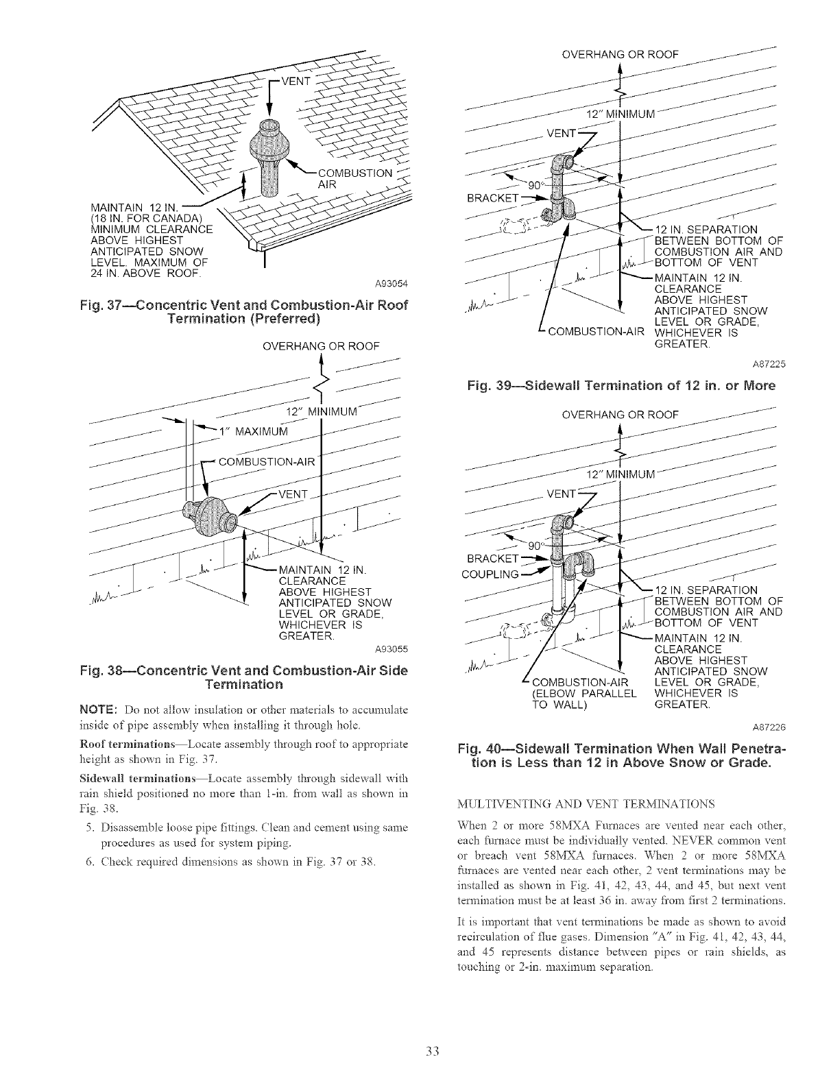
Fig. 37--Concentric Vent and Combustion=Air Roof
Termination (Preferred}
12 IN.
CLEARANCE
ABOVE HIGHEST
ANTICIPATED SNOW
LEVEL OR GRADE,
WHICHEVER IS
GREATER.
A93055
Fig. 38--Concentric Vent and Combustion-Air Side
Termination
NOTE: Do not allow insulation or other materials to accumulate
inside of pipe assembly when installing it through hole
Roof ternfi.adons Locate assembly through roof to appropriate
height as shown in Fig. 37,
Sidewall terminations Locate assembly through sidewall with
rain shield positioned no more than l=in fi'om wall as shown in
Fig 38,
5, Disassemble loose pipe fittings. Clean and cement using same
procedures as used for system piping.
6, Check required dimensions as shown in Fig 37 or 38,
IN. SEPARATION
BOTTOM OF
COMBUSTION AIR AND
OF VENT
12 IN.
CLEARANCE
ABOVE HIGHEST
ANTICIPATED SNOW
LEVEL OR GRADE,
COMBUSTION-AIR WHICHEVER IS
GREATER.
A87225
Fig. 39--Sidewall Termination of 12 in. or More
OVERHANG OR ROOF /_,-----_/"
VENT-""* / /_
_ 90 °
BRACKET
COUPLING
/" I It l_-->< ! x-12 iN.SEPARATION
/" _ _d _ [-/_/BETWEEN BOTTOM OF
_a_/l_--- I .COMBUSTIONAIR AND
J_ ,,7__r_/_" . 1_71BOTTOM OF VENT
/_?- 77 J,_ /f""'--'MAINTAIN 12 IN.
•/ /_ _/ cLEARANCE
_k!g ---¢-'- _/ _ _ABOVE HIGHEST
-" _ '--ANTICIPATED SNOW
"-COMBUSTION-AIR LEVEL OR GRADE,
(ELBOW PARALLEL WHICHEVER IS
TO WALL) GREATER.
A87226
Fig. 40--Sidewall Termination When Wall Penetra-
tion is Less than 12 in Above Snow or Grade.
MULTIVENTING AND VENT TERMINATIONS
When 2 or more 58MXA Furnaces are vented near each other,
each f_lrnace must be individually vented. NEVER common vent
or breach vent 58MXA furnaces. When 2 or more 58MXA
furnaces are vented near each other, 2 vent tem_inations may be
installed as shown in Fig. 41, 42, 43, 44, and 45, but next vent
termination must be at least 36 in. away fi'om first 2terminations.
It is important that vent terminations be made as shown to avoid
recirculation of flue gases. Dimension "A" in Fig. 41, 42, 43, 44,
and 45 represents distance between pipes or rain shields, as
touching or 2=in. maximum separation.
33
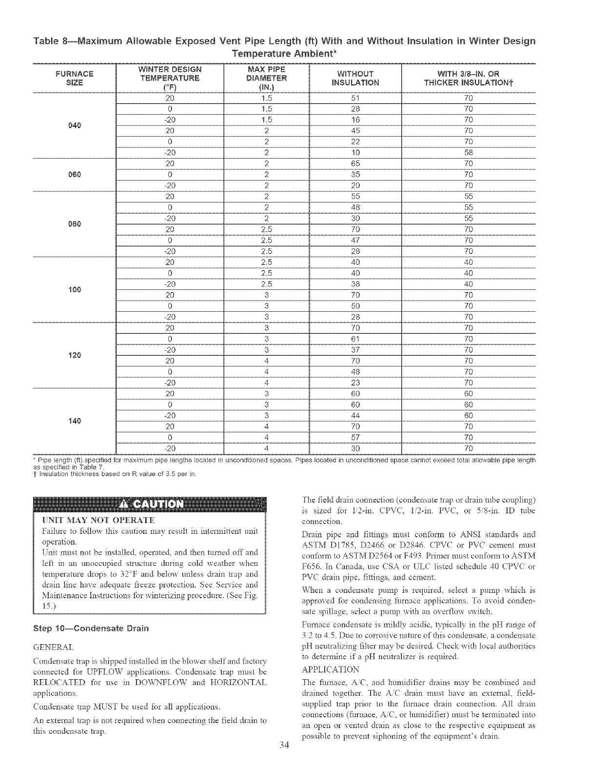
TaNe 8--Maximum AItowaNe Exposed Vent Pipe Length (ft) With and Without Insulation in Winter Design
Temperature Ambient*
WINTER DESIGN MAX PIPE
FURNACE W_THOUT W_TH 3/8-1N. OR
TEMPERATURE DIAMETER
SRZE (OF) (BN.) INSULATION THICKER INSULATIONt
20 1.5 51 70
0 1.5 28 70
-20 1.5 16 70
040 20 2 45 70
0 2 22 70
-20 2 10 58
20 2 65 70
060 0 2 35 70
-20 2 20 70
20 2 55 55
0 2 48 55
-20 2 30 55
080 20 2.5 70 70
0 2.5 47 70
-20 2.5 28 70
20 2.5 40 40
0 2.5 40 40
-20 2.5 38 40
100 20 3 70 70
0 3 50 70
-20 3 28 70
20 3 70 70
0 3 61 70
-20 3 37 70
120 20 4 70 70
0 4 48 70
-20 4 23 70
20 3 60 60
0 3 60 60
-20 3 44 60
140 20 4 70 70
0 4 57 70
-20 4 30 70
* Pipe length (if) specified _r maximum pipe lengths located unconditioned
as specified in Table 7.
tInsulation thickness based on R vNue of 35 per in
spaces. Pipes located in unconditioned space cannot exceed total allowable pipe length
[?NIT MAY NOT OPERATE
Failure to follow this caution may result in intermittent unit
operation
Unit must not be installed, operated, and then mined off and
left in an unoccupied structure during cold weather when
temperature drops to 32cT and below unless &ain trap and
drain line have adequate t'reeze protection. See Service and
Maintenance Instructions for winterizing procedure (See Fig
15.)
Step 10--Condensate Drain
GENERAL
( ondensate trap is shipped installed in the blower shelf and factow
connected for UPFLOW applications (ondensate trap must be
RELOCATED for use in DOWNFLOW and HORIZONTAL
applications.
(ondensate trap MUST be used for all applications.
An external trap isnot required when connecting the field drain to
this condensate trap.
34
The field drain connection (condensate trap or drain robe coupling)
is sized for ti2=in. CPV(, li2-in PV(, or 5/g-in. ID robe
connection.
Drain pipe and fittings must confbm_ to ANSI standards and
ASTM D1785, D2466 or D2846. CPVC or PVC cement must
confc_rm to ASTM D2564 or F493. Primer must conform to ASTM
F656. In Canada, use CSA or ULC listed schedule 40 (PVC or
PVC drain pipe, fittings, and cement.
When a condensate pump is required, select a pump which is
approved fbr condensing Nmace applications. To avoid conden=
sate spillage, select a pump with an overflow switch.
Furnace condensate is mildly acidic, typically in the pH range of
3.2 to 4.5. Due to corrosive nature of this condensate, a condensate
pH neutralizing filter may be desired. Check with local authorities
to determine if a pH neutralizer is required.
APPLICATION
The furnace, A/C, and humidifier drains may be combined and
drained together. The AiC &ain must have an external, field=
supplied trap prior to the _ilrnace &ain connection. All &ain
connections (t:urnace, Ai(, or humidifier) must be temlinated into
an open or vented drain as close to the respective equipment as
possible to prevent siphoning of the equipment's drain.
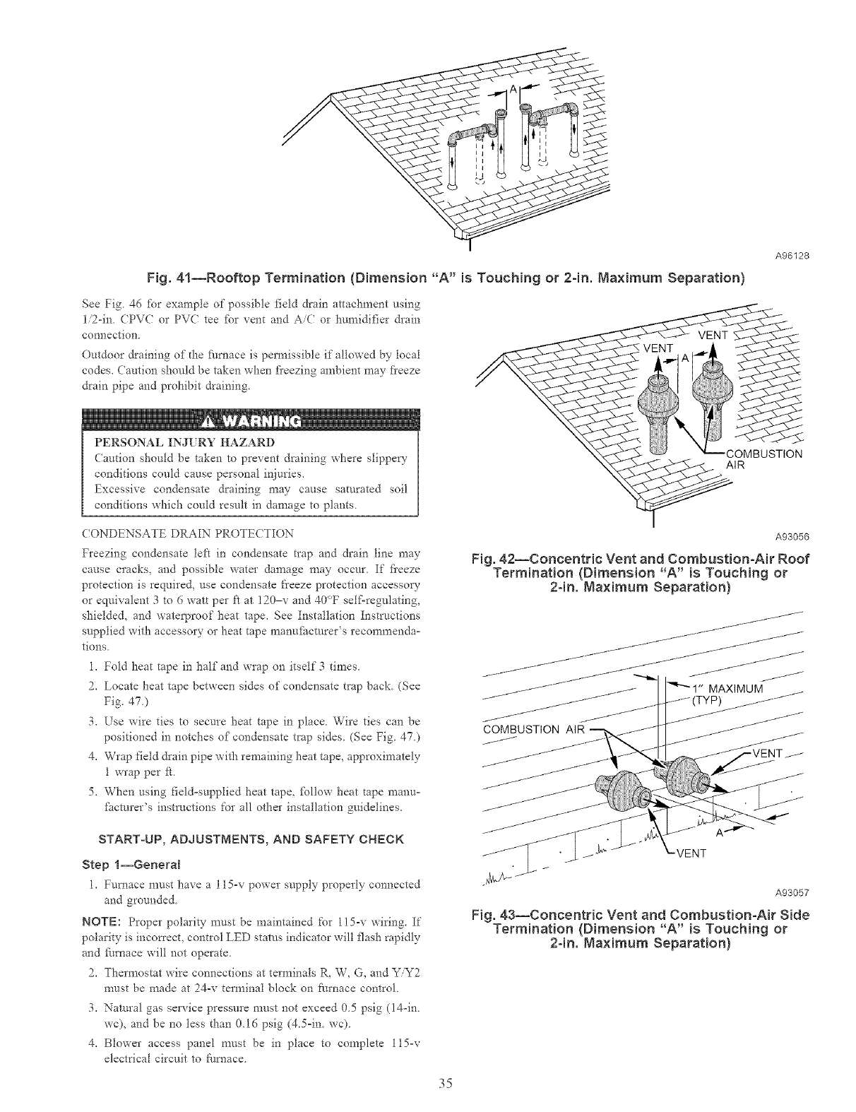
A96128
Fig. 41--Rooftop Termination (Dimension "A" is Touching or 2=in. Maximum Separation)
See Fig 46 %r example of possible t_eld drain attachment using
1/2-in CPV( or PVC tee fbr vent and Ai( or humidifier &ain
connection.
Outdoor draining of the ii/mace is permissible if allowed by local
codes. Caution should be taken when fi'eezing ambient may fieeze
drain pipe and prohibit draining.
PERSONAL INJ[ R¥ HAZARD
Caution should be taken to prevent draining where slippeQ'
conditions could cause personal injuries.
Excessive condensate draining may cause saturated soil
conditions which conld result in damage to plants
COMBUSTION
AIR
(ONDENSATE DRAIN PROTE(TION
Freezing condensate left in condensate trap and drain line may
cause cracks, and possible water damage may occur. If fieeze
protection is required, use condensate freeze protection accesso_
or equivalent 3 to 6 watt per ft at 120 v and 40°F self-regulating,
shielded, and waterproof heat tape. See Installation Instructions
supplied with accessory or heat tape manuihcmrer's recomrnenda°
tions.
1. Fold heat tape in half and wrap on itself 3 times.
2. Locate heat tape between sides of condensate trap back. (See
Fig. 47.)
3. Use wire ties to secure heat tape in place. Wire ties can be
positioned in notches of condensate trap sides. (See Fig. 47.)
4. Wrap field &ain pipe with remaining heat tape, approximately
1 wrap per k.
5. When using field=supplied heat tape, _bllow heat tape manu=
_hcmrer's instructions for all other installation guidelines.
A93056
Fig. 42--Concentric Vent and Combustion-Air Roof
Termination (Dimension "A" is Touching or
2-in. Maximum Separation)
START-UP, ADJUSTMENTS, AND SAFETY CHECK
Step l--General
l. Furnace m_/st have a 115-v power supply properly connected
and gronnded
NOTE: Proper polarity must be maintained for l15-v wiring. If
polarity is incmTect, control LED status indicator will flash rapidly
and furnace will not operate.
2. Thermostat wire connections at terminals R, W, G, and Y/Y2
must be made at 24-v terminal block on t:urnace control.
3. Natural gas service pressure must not exceed 0.5 psig (14=in.
wc), and be no tess than 0.16 psig (4.5=in. wc).
4. Blower access panel must be in place to complete l15-v
electrical circuit to filrnace.
VENT
A93057
Fig. 43--Concentric Vent and Combustion-Air Side
Termination (Dimension "A" is Touching or
2-in. Maximum Separation)
35
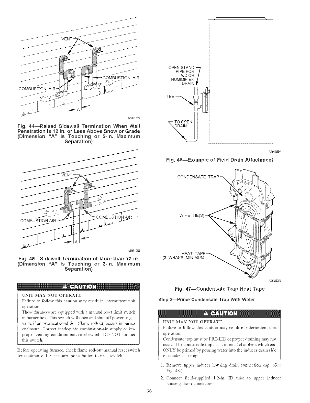
_/// _1t/_
COMBUSTION
J
JAIR
A96129
Fig. 44_Raised SidewNl Termination When Wail
Penetration is 12 in. or Less Above Snow or Grade
(Dimension "A" is Touching or 2=in. Maximum
Separation}
/
J
OPEN STAND -'7
PIPE FOR /
A/COR/
HUMIDIFIER d
DRAIN
TEE U_
A94054
Fig. 46--Example of Field Drain Attachment
CONDENSATE
COMBUSTION AIR
A96130
Fig. 45--Sidewall Termination of More than 12 in.
(Dimension "A" is Touching or 2-in. Maximum
Separation}
UNIT MAY NOT OPERATE
Failure to follow this caution may result in intermittent unit
operation
These furnaces are equipped with a manual reset limit switch
in burner box. This switch wil! open and shut offpower to gas
valve if an overheat condition (flame rollout) occurs in burner
enclosure. Correct inadequate combustion=air supply or ira=
proper venting condition and reset switch. DO NOT jumper
this switch_
Befbre operating fumacQ check flanre roll=out manual reset switch
for continuity_ If necessaD', press button to reset sx_itch
WIRE TIEq
HEAT
(3 WRAPS MINIMUM)
36
A93036
Fig. 47--Condensate Trap Heat Tape
Step 2--Prime Condensate Trap With Water
UNIT MAY NOT OPERATE
Failure to _bltow this caution may result in intem_ittent unit
operatiom
Condensate trap must be PRIMED or proper draining may not
occur The condensate trap has 2internal chambers which can
ONLY be primed by pouring water into the inducer drain side
of condensate trap_
1_ Remove upper inducer housing &ain connection caD (See
Fig. 48.)
Z (onnect fiel&supplied 1i2=in_ ID robe to upper inducer
housing &ain connection.
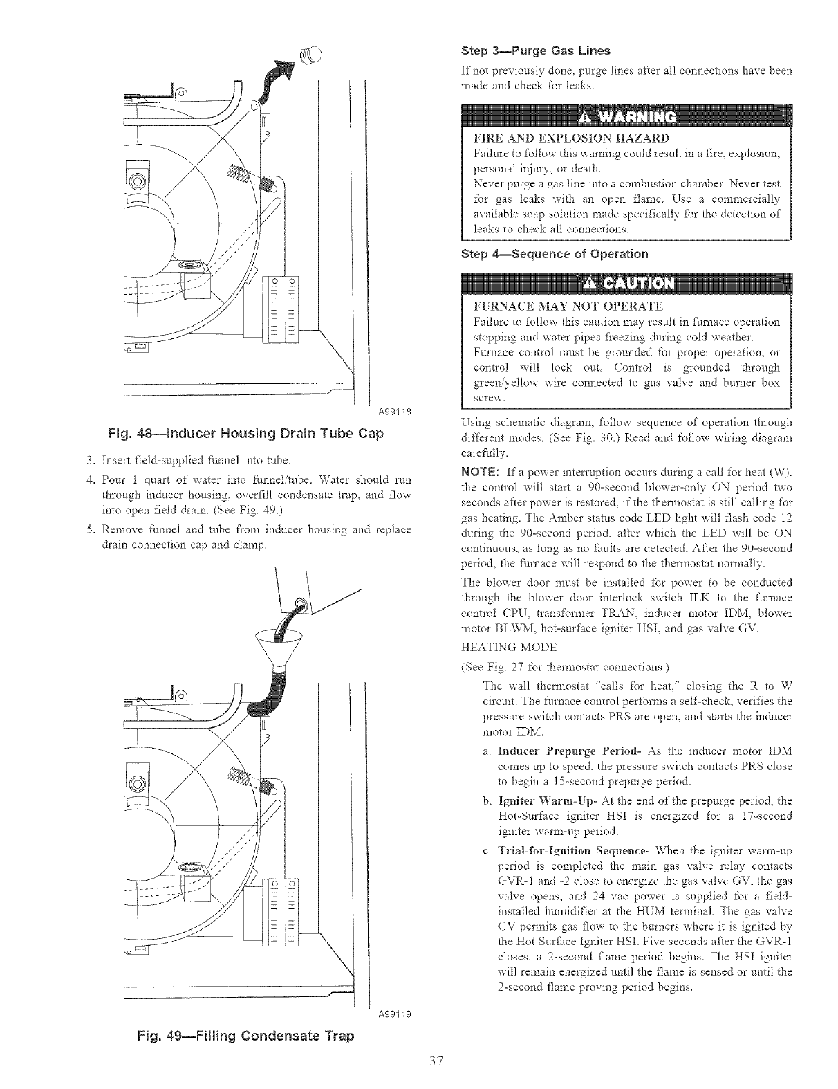
A99118
Fig. 48--Inducer Housing Drain Tube Cap
3. Insert field=supplied flmnel into tube.
4. Pour 1 quart of water into funnel/robe. Water sho_fld run
through inducer housing, overfill condensate trap, and flow
into open field drain. (See Fig 49.)
5. Remove flmnel and robe from inducer housing and replace
&ain connection cap and clamp.
A99119
Fig. 49--Filling Condensate Trap
37
Step 3--Purge Gas Lines
If not previously done, purge lines after all connections have been
made and check tbr leaks.
iiiii_, 1,_: iiiiiil,.
FIRE AND EXPLOSION HAZARD
Failure to follow this warning could result in a fire, explosion,
personal it!ire'y, or death.
Never purge a gas line into a combustion chamber. Never test
_br gas leaks with an open flame Use a commercially
available soap solution made specifically _br the detection of
leaks to check all connections.
Step 4--Sequence of Operation
F! RNACE MAY NOT OPERATE
Failure to _bllow this caution may result in flu'nace operation
stopping and water pipes fi'eezing during cold weather
Furnace control must be grounded _br proper operation, or
control will lock out Control is grounded d_rough
green yellow wire connected to gas valve and burner box
screw.
Using schematic diagram, follow sequence of operation through
di_:_krent modes. (See Fig. 30.) Read and follow wiring diagram
carefully.
NOTE: Ifa power interruption occurs during a call [br heat (W),
the control will start a 90=second blower=only ON period two
seconds after power is restored, if the thermostat is still calling _br
gas heating. The Amber status code LED light will flash code 12
during the 90=second period, after which the LED will be ON
continuous, as tong as no faults are detected After the 90=second
period, the fl/mace will respond to the thermostat normally.
The blower door must be installed _br power to be conducted
through the blower door interlock switch ILK to the furnace
contloi CPU, transformer TRAN, inducer motor IDM, blower
motor BLWM, hot=surfitce igniter HSI, and gas valve GV.
HEATING MODE
(See Fig. 27 for thermostat connections.)
The wall thermostat "calls for heat," closing the R to W
circuit. The furnace control performs a self=check, verifies the
pressure switch contacts PRS are open, and starts the inducer
motor IDM.
a. Inducer Prepurge Period= As the inducer motor IDM
comes up to speed, the pressure switch contacts PRS close
to begin a 15-second prepurge period.
b. Igniter '_¥arm-[ p- At the end of the prepurge period, the
Hot-Surface igniter HSI is energized for a 17=second
igniter warm-up period.
c. Trial-Nr-Ignition Sequence- When the igniter warm-up
period is completed the main gas valve relay contacts
GVR-I and -2 close to energize the gas valve GV, the gas
valve opens, and 24 vac power is supplied for a field-
installed humidifier at the HUM terminal. The gas valve
GV permits gas flow to the burners where it is ignited by
the Hot Surfhce Igniter HSI. Five seconds after the GVR=I
closes, a 2-second flame period begins. The HSI igniter
will remain energized until the flame is sensed or until the
2-second flame proving period begins.
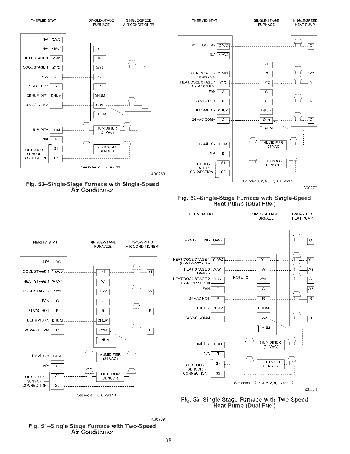
THERMIDISTAT SINGLE-STAGE SINGLE-SPEED THERMIDISTAT SINGLE-STAGE SiNGLE-SPEED
FURNACE AIR CONDITIONER FURNACE HEAT PUMP
N_A
NIA
HEAT STAGE 1
COOL STAGE 1 [_
FAN _-
24 VAC HOT [_
DEHGM}D}FY
24 VAC COMM
HUMIDIFY
N/A [_
OUTDOORF_
c&E"&OT,%Q[2_
HUM
z_ E HUMIDIFIER
(24 VAC)
OUTDOOR
SENSOR
See notes 2, 5, 7, and 10
A00268
Fig. 50-Single-Stage Furnace with Single-Speed
Air Conditioner
RVS COOLING
N/A
HEAT STAGE 2
(FURNACE)
HEAT/COOL STAGE 1
(COMPRESSOR)
FAN [_
24 VAC HOT [_
DEHUMIDIFY [_
24 VAC COMM [_
HUMIDIFY
N/A
C_
[_ HUM
_[2_ OUTDOOR
OUTDOOR SENSOR
SENSOR
CONNECTION _ _ __ i
See notes 1, 2, 4, 6, 7, 9, 10 and 12
A00270
Fig. 52-Single-Stage Furnace with Single-Speed
Heat Pump (Dua! Fuel)
THERM;D;STAT SINGLE-STAGE TWO-SPEED
FURNACE HEATPUMP
THERMIDISTAT SINGLE-STAGE TWO-SPEED
FURNACE AIR CONDITIONER
N_
COOLSTAGEI_
dEATSTAGEI_
COOLSTAGE2_
FAN_
24 MAC HOT
DEHUMIDIFY
24 VAC COMM [_
HUMIDIFY [_
N/A
O0TDOO*_
_HUMI'"-
J_'WJ HUMIDIFIER
(24 VAC }
L
LSENSOR
See notes 2, 5, 8, and 10
A00269
Fig. 51-Single Stage Furnace with Two-Speed
Air Conditioner
3g
RVS COOLING
HEA(rc/COOFLSTAG LEc1)_ ............... _ ............ _ _
H EAIFSuTAGcEE: [_ _ l _]_
........
FAN_ .............._ []
_,MACHOT_......... _ 2_
DEHOM'D'FY
_4MACCOMM_ ....... \ ...... []
HUMIDIFIER
HUMIDIFY _ (24 VAC)
N/A
CONNECT'ON
See notes 1, 2, 3, 4, 6, 8, 9,10 and 12
A00271
Fig. 53-Single-Stage Furnace with Two-Speed
Heat Pump (Dual Fuel)
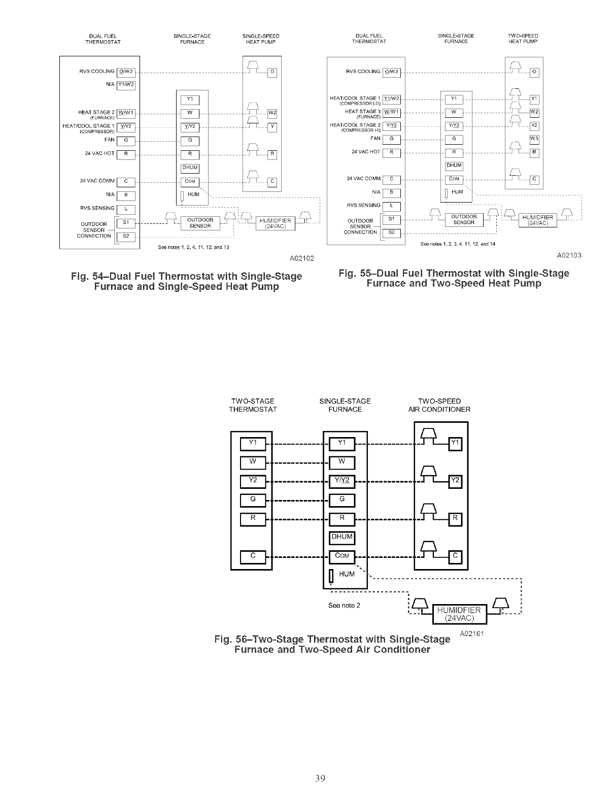
DUAL FUEL SINGLE-STAGE SINGLE-SPEED DUAL FUEL SINGLE-STAGE TWO-SPEED
THERMOSTAT FURNACE HEAT PUMP THERMOSTAT FURNACE HEAT PUMP
RVS COOLING
NfA [_
HEATSTAGE2
(FURNACE) [_
HEAT/COOLSTAGE1
(COMPRESSOR)_
FAN[_
24 VAC HOT[_
24 VAC COMM [_
N/A [_
RVS SENSING [_
DONNECT,ON
] I]_____[_
See netes1, 2, 4 ,11,12, and13
A02102
Fig. 54-Dua{ Fuel Thermostat with Single-Stage
Furnace and Single-Speed Heat Pump
RVS COOLING
HEAT/COOL STAGE 1
(COMPRESSOR LO)
HEAT/COOL STAGE 2
(COMPRESSOR HI)
FAN
24 VAC HOT [_
24 VAC COMM [_
RVS SENSING [_
OUTDOOR _[_
co_c°,_o_[_
'] F []
i iii ¸¸
See notes 1, 2, 3, 4 11,12, and 14
A02103
Fig. 55-Dua{ Fuel Thermostat with Single-Stage
Furnace and Two-Speed Heat Pump
TWO-STAGE SINGLE-STAGE TWO-SPEED
THERMOSTAT FURNACE AIR CONDITIONER
ED -pq
mI1 HUM
See note 2 ', HUMIDFIER _..
(24VAC)
A02161
Fig. 56-Two-Stage Thermostat with Single-Stage
Furnace and Two-Speed Air Conditioner
39
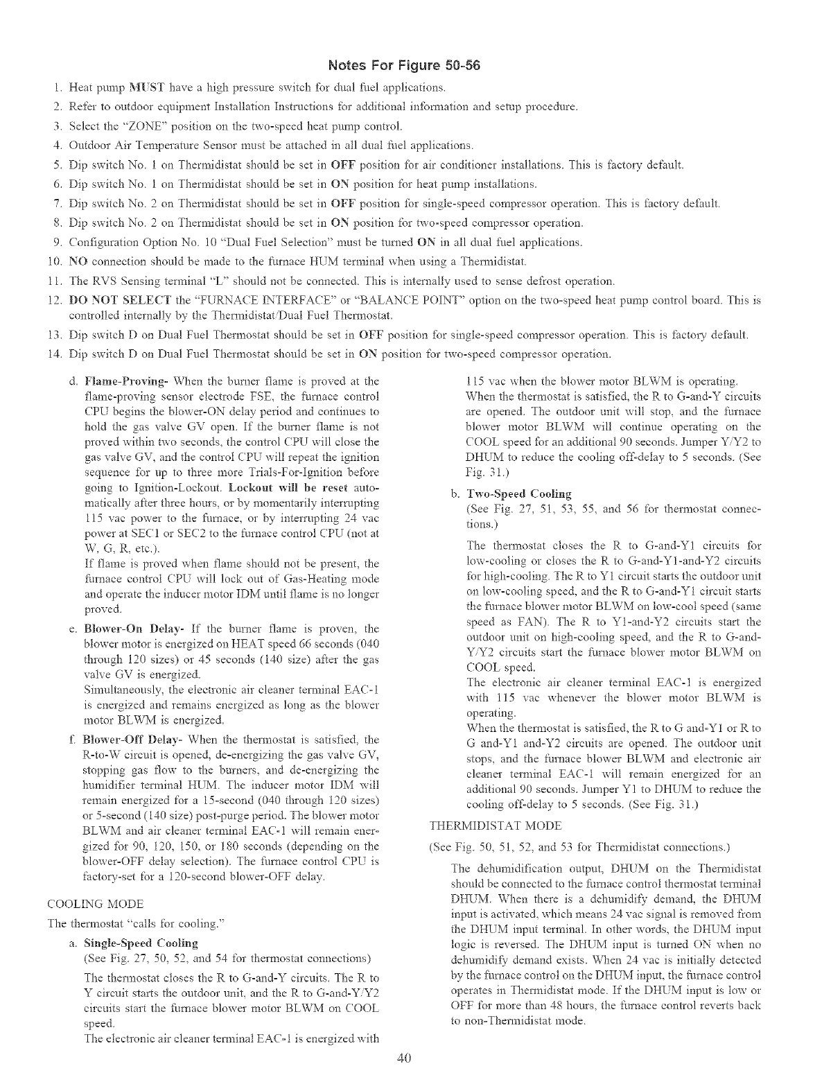
Notes For Figure 50°56
1. Heat pump M_ST have a high pressm'e switch l\_r dual f_lel applications.
2. Refer to outdoor equipment Installation Instructions _br additional in*bm_ation and setup procedure.
3. Select the "ZONE" position on the two=speed heat pump control.
4. Outdoor Air Temperature Sensor must be attached in all dual fuel applications
5. Dip switch No 1 on Thermidistat should be set in OFF position _br air conditioner installations This is _ctory dePault.
6. Dip switch No 1 on Thermidistat should be set in ON position for heat pump installations.
7. Dip switch No 2 on Thenr_idistat should be set in OFF position t:br single-speed compressor operation. This is _cto W default
8. Dip switch No 2 on Thermidistat should be set in ON position for two-speed compressor operation.
9. (or*figuration Option No 10 "Dual Fuel Selection" must be mined ON in all daal _hel applications.
10. NO connection should be made to the furnace HI_M terminal when using a Thermidistat
11. The RVS Sensing terminal "L" should not be connected This is internally used m sense def_'ost operation
12. DO NOT SELECT the "FUPC\'A( E INTERFACE" or "BALAN(E POINT" option on the two=speed heat pump control board. This is
controlled internally by the ThermidistatiDual Fuel Them_ostat.
13. Dip switch D on Dual Fuel Thermostat shoutd be set in OFF position tbr single-speed compressor operation This is i:actoW default.
14. Dip switch D on Dual Fuel Thermostat shoutd be set in ON position for two-speed compressor operation.
d. Flame-Proving- When the burner flame is proved at the
flame-proving sensor electrode FSE, fl-_efhmace control
CPU begins the blower=ON delay period and continues to
hold the gas valve GV open. If the burner flame is not
proved within two seconds, the control CPU will ctose the
gas valve GV, and the control CPU will repeat the ignition
sequence _br up to three more Trials=For-Ignition before
going to Ignition=Lockout. Lockout will be reset auto-
matically af'te, three hou*s, or by momentarily interrupting
115 vac power to tl_e _k/rnace, or by interrupting 24 vac
powe* at SEC 1 or SEC2 to the fro'hate control CPU (not at
W, G, R, etc.).
If flame is proved when flame should not be present, the
furnace control CP[ will lock out of Gas-Heating mode
and operate the in&cer motor IDM until flame is no tonger
proved.
e. Blower-On Delay- If the burner flame is proven, the
blower motor is energized on HEAT speed 66 seconds (040
through 120 sizes) or 45 seconds (140 size) aker the gas
valve GV is energized.
Simultaneously, the electronic air cleaner tem_inai EAC-1
is energized and remains energized as long as the blower
motor BLWM is energized.
E Blower-Off Delay- When the the*mostat is satisfied, the
R=to-W circuit is opened, de=energizing the gas valve GV,
stopping gas 13ow to the burners, and de-energizing the
humidifier terminal HUM The inducer motor IDM will
remain energized for a 15=second (040 through 120 sizes)
or 5=second (I40 size) post=purge pe*iod. The blower motor
BLWM and air cleaner terminal EAC-I will remain ener-
gized fbr 90, 120, 150, or 180 seconds (depending on the
blower-OFF delay selection). The finlaace colmol CP[ is
factow-set for a 120-second blower-OFF delay.
( OOLING MODE
The them_ostat "calls for cooling."
a, Single-Speed Cooling
(See Fig. 27, 50, 52, and 54 for thermostat connections)
The d'*ermostat closes the R to G-and=Y circuits. The R to
Y circuit starts the outdoor unit, and the R to G-and-Y/Y2
circuits start the furnace blower motor BLWM on (OOL
speed.
The etect*onic air cleaner tem_inal EAC= 1is energized with
115 vac when the blower motor BLWM is operating.
When the thermostat is satisfied, the R to G=and-Y circuits
are opened. The outdoor unit will stop, and the furnace
blower motor BLWM wi!l continue operating on the
COOL speed fbr an additional 90 seconds. Jumper Y/Y2 to
DHUM to reduce the cooling off-delay to 5 seconds (See
Fig. 3!)
b, Two-Speed (ooling
(See Fig. 27, 51, 53, 55, and 56 for thermostat connec-
tions.)
The thermostat closes the R to G-and-Y1 circuits fbr
low-cooling or closes the R to G-and-Yl-and-Y2 circuits
_br high-cooling The Rto YI circuit starts the outdoor unit
on low-cooling speed, and the R to G-and-Y1 el*cult starts
the furnace blower motor BLWM on low-coot speed (same
speed as FAN) The Rto Yl-and-Y2 circuits start the
outdoor unit on high-cooling speed, and the R to G-and-
Y/Y2 circuits start the fi/rnace blower motor BLWM on
COOL speed.
The electronic air cleaner terminal EAC-1 is energized
with 115 vac whenever the blower motor BLWM is
operating.
When the thermostat is satisfied, the R to G and-Y1 or R to
G and-Y1 and-Y2 circuits a*e opened. The outdoor unit
stops, and the furnace blower BLWM and electronic air
cleaner te*minal EAC-1 will remain energized for an
additional 90 seconds. Jumper Y1 to DHUM to reduce the
cooling off'delay to 5 seconds (See Fig. 3i)
THERMIDISTAT MODE
(See Fig. 50, 51, 52, and 53 fbr Them_idistat connections.)
The dehumidification output, DHI_M on the Them_idistat
should be connected to the furnace control thermostat terminal
DHUM. When there is a dehumidify demand, the DHI_M
input is activated, which means 24 vac signal is removed ['rom
the DHUM input terminal. In other words, the DHUM input
logic is reversed. The DHUM input is turned ON when no
dehumidif) demand exists. When 24 vac is initially detected
by the fine, ace control on the DHUM input, the flmaace control
operates in Themaidistat mode. If the DHUM input is tow or
OFF for more than 48 hours, the [:umace control reverts back
to non=Thermidistat mode.
40
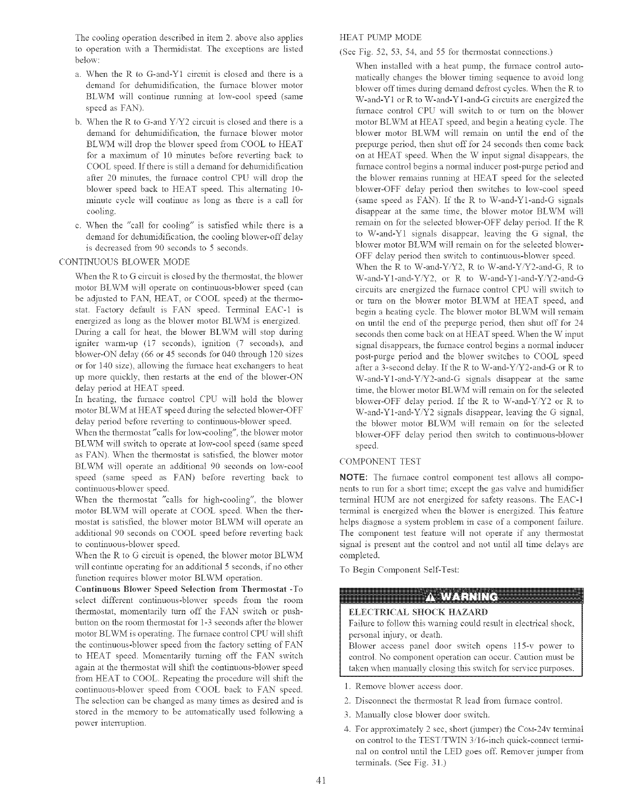
The cooling operation described in item 2above also applies
to operation with a Tl"_ermidistat The exceptions are listed
below:
a. When the R to G-and-Y1 circuit is closed and there is a
demand fbr dehumidification, the furnace blower motor
BLWM will continue running at low-cool speed (same
speed as FAN).
b. When the R to G-and Y/Y2 circuit is closed and there is a
demand for dehumidification, the furnace blower motor
BLWM will drop the blower speed flora COOL to HEAT
fbr a maximum of i0 minutes before reverting back to
(OOL speed. If there is still a demand h_r dehumidification
after 20 minutes, the furnace control CPI_ will drop tl-_e
blower speed back to HEAT speed. This alternating 10-
minute cycle will continue as tong as there is a call for
cooling.
c. When the "call for cooling" is satisfied while there is a
demand for dehumidification, the cooling blower-off delay
is decreased fi'om 90 seconds to 5 seconds,
CONTIN/OUS BLOWER MODE
When the R to G circuit is closed by the thermostat, the blower
motor BLWM will operate on continuous-blower speed (can
be adjusted to FAN, HEAT, or COOL speed) at the tl",ermo-
star. Factory- default is FAN" speed. Tem_inal EAC-1 is
energized as long as the blower motor BLWM is energized
During a call fbr heat, the blower BLWM will stop during
igniter warn>up (17 seconds), ignition (7 seconds), and
blower-ON delay (66 or 45 seconds for 040 through 120 sizes
or fbr 140 size), allowing the fiu'nace heat exchangers to heat
up more quickly, then restarts at the end of the blower-ON
delay period at HEAT speed.
In heating, the filmace control CPU will hold the blower
motor BLWM at HEAT speed during the selected blower-OFF
delay period before reverting to continuous-blower speed.
When the thermostat "calls h_r tow-cooling", the blower motor
BLWM will switch to operate at tow-cool speed (same speed
as FAN) When the them_ostat is satisfied, the blower motor
BLWM will operate an additional 90 seconds on lmv-coot
speed (same speed as FAN) befbre reve*ting back to
continuous-blower speed
When the thermostat "calls for high-cooling", the blowe*
motor BLWM will operate at COOL speed. When the the*-
mostat is satisfied, the blower motor BLWM will operate an
additional 90 seconds on (OOL speed before reverting back
to continuous-blower speed
When the Rto G circuit is opened, the blower motor BLWM
will continue operating for an additional 5 seconds, if'no other
fhnction requires blower motor BLWM operation
Continuous Blower Speed Selection from Thermostat -To
select different continuous-blower speeds from the room
thermostat, momentarily trim off the FAN' switch or push-
button on the room thermostat for 1-3 seconds are*"the blower
motor BLWM is operating. The fhmace control CPU will shift
the continuous=blower speed fi'om the fi_ctoW setting of FAN
to HEAT speed. Momentarily turning off the FAN" switch
again at the thermostat will shik the continuous-blower speed
fi'om HEAT to COOL. Repeating the procedure will shift the
continuous-blower speed fi'om COOL back to FAN" speed.
The selection can be changed as many times as desired and is
stored in the memoD" to be automatically used following a
power inten'uption.
41
HEAT PUMP MODE
(See Fig. 52, 53, 54, and 55 %r them_ostat connections)
When installed with a heat pump, the furnace control auto-
matically changes the blower timing sequence to avoid long
blower ofttimes during demand defrost cycles When the R to
W-and-Y 1 or R to W-and-Y l-and-G circuits are energized the
fhmace control (PU will switch to or mrn on the blower
motor BLWM at HEAT speed, and begin a heating cycle The
blower motor BLWM wilt remain on until the end of the
prepurge period, then shut off for 24 seconds _hen come back
on at HEAT speed When tl_e W input signal disappears, the
fimaace control begins a normal inducer post-purge period and
the blower remains rmming at HEAT speed fPr the selected
blower-OFF delay period then switches to low-cool speed
(same speed as FAN) If the R to W-and-Yl-and-G signals
disappear at tl-_e same time, the blower motor BLWM will
remain on fbr the selected blower-OFF delay period. If the R
to W-and-Y1 signals disappear, leaving the G signal, the
blower motor BLWM will remain on for the selected blower-
OFF delay period then switch to continuous-blower speed.
When the R to W-and-Y/Y2, R to W-and-Y Y2-and-G, R to
W-and-Yl-and-YY2, or R to W-and-Yl-and-YiY2-and-G
circuits are energized the hm_ace control (PU will switch to
or mm on the blower motor BLWM at HEAT speed, and
begin a heating cycle The blower motor BLWM will remain
on until the end of the prepurge period, then shut off for 24
seconds then come back on at HEAT speed. When the W input
signal disappears, the fi/mace contIol begins a normal inducer
post-purge period and the blower switches to COOL speed
after a 3-second delay. If the R to W-and-YiY2-and-G or R to
W-and-Yl-and-YY2-and-G signals disappear at the same
time, the blower motor BLWM will remain on fbr the selected
blower-OFF delay period. If the R to W-and-YY2 or R to
W-and-Yl-and-Y Y2 signals disappear, leaving the G signal,
the blower motor BLWM will remain on for the selected
blower-OFF delay period then switch to continuous-blower
speed.
COMPONENT TEST
NOTE: The furnace contlol component test allows all compo-
nents to run fbr a short time; except the gas valve and humidifier
terminal HUM are not energized fbr safety reasons. The EA(-I
terminal is energized when the blower is energized. This fkature
helps diagnose a system problem in case of a component fitilure.
The component test feature will not operate if any thermostat
signal is present ant the control and not until all time delays are
completed.
To Begin Component Self=Test:
ELECTRICAL SHOCK HAZARD
Failure to fbllow this warning could result in electrical shock,
personal i_.imy,or death.
Blower access panel door switch opens l15-v power to
control. No component operation can occur. Caution must be
taken when manually closing this switch fPr service purposes.
1. Remove blower access door.
2. Disconnect the thermostat R lead f?om furnace control.
3. Manually close blower door switch.
4. For approximately 2sec, short (lumper) the Cox_-24v tem_inal
on contlol to the TEST/TWIN 3/16-inch quick-connect termi-
nal on control until the LED goes oftl Remover jumper from
terminals. (See Fig. 3!.)
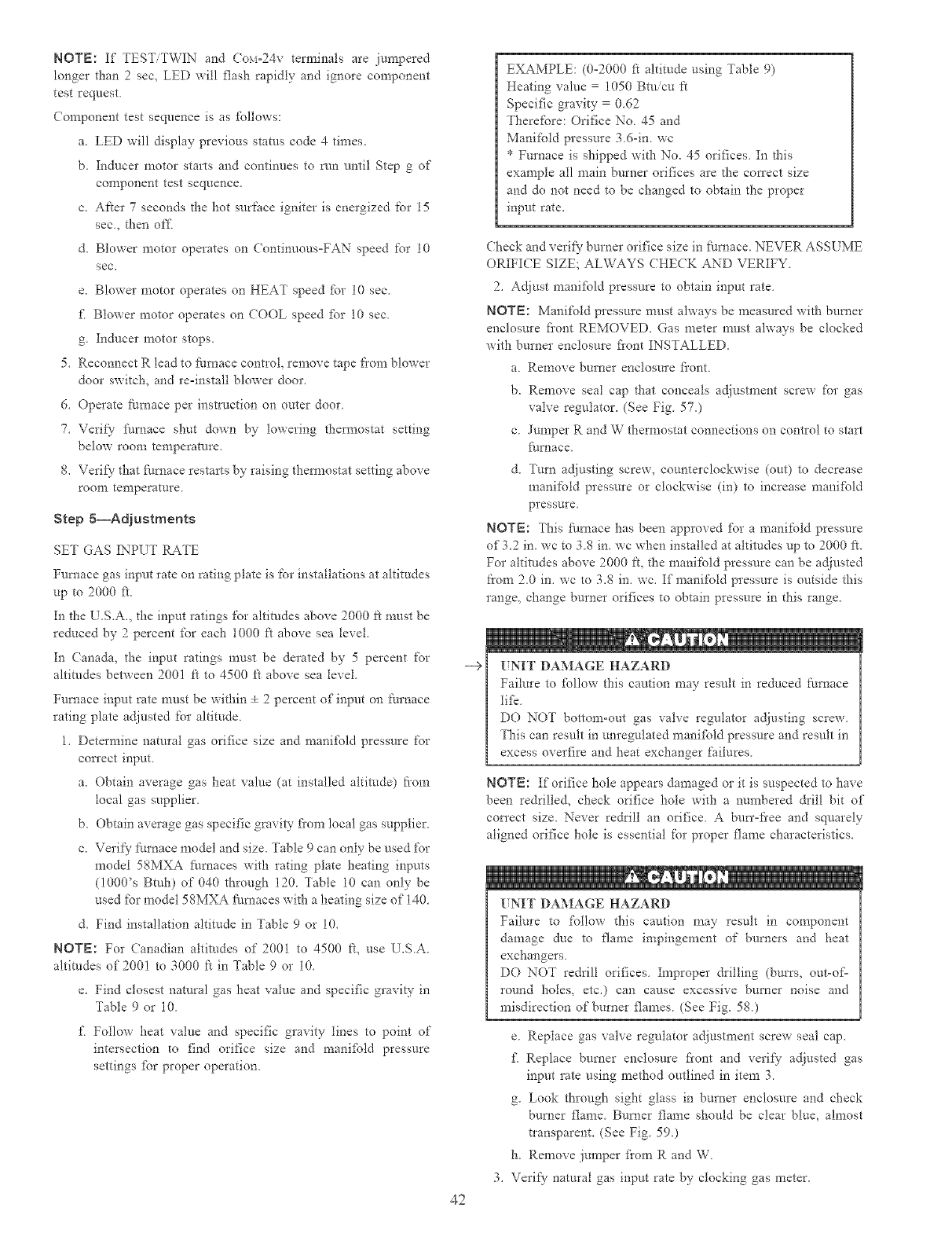
NOTE:If TEST/TWINandCOM-24Vterminalsarejm_apered
longerthan2sec, LED will flash rapidly and ignore component
test request
Component test sequence is as ibllows:
a. LED will display previous stares code 4 times.
b. Inducer motor starts and continues to run until Step g of
component test sequence.
c. After 7 seconds the hot surface igniter is energized for 15
see., then of£
d. Blower motor operates on (ontinuous=FAN speed for 10
see.
e. Blower motor operates on HEAT speed £_r 10 sec.
£ Blower motor operates on COOL speed _br 10 sec.
g. Inducer motor stops.
5. Reconnect R lead to furnace contlol, remove tape fiom blower
door switch, and re=install blower door.
6. Operate furnace per instruction on outer door.
7. Verii}" ihmace shut down by lowering thermostat setting
below room temperature.
8. Verify7 that filrnace restarts by raising them_ostat setting above
roonl temperature
Step 5--Adjustments
SET GAS INPUT RATE
Furnace gas input rate on rating plate is %r installations at altitudes
up to 2000 ft.
In the U.S.A., the input ratings for altitudes above 2000 ft must be
reduced by 2 percent fbr each 1000 ft above sea level.
In Canada, the input ratings must be derated by 5 percent for
altitudes between 2001 ft to 4500 ft above sea level.
Furnace input rate must be within ÷ 2 percent of input on [_urnace
rating plate adjusted for altitude
1. Determine natural gas orifice size and manifPld pressure for
correct input
a. Obtain average gas heat value (at installed altitude) fi'om
local gas supplier.
b. Obtain average gas specific gravity fiom local gas supplier
c. Verii}' f_m'nace model and size. Table 9 can only be used for
model 5gMXA fhmaces with rating plate heating inputs
(1000's Btuh) of 040 through 120. Table 10 can only be
used fbr model 58MXA fhmaces with a heating size of 140.
d. Find installation altitude in Table 9 or 10.
NOTE: For Canadian altitudes of 2001 to 4500 It, use L.SA
altitudes of 200! to 3000 ft in Table 9 or 10.
e. Find closest natural gas heat value and specific gravity in
Table 9 or 10.
£ Follow heat value and specific gravity lines to point of
intersection to find orifice size and manifbld pressure
settings fbr proper operation.
--€
42
EXAMPLE: (0-2000 fi altitude using Table 9)
Heating value 1050 Btuicu ft
Specific gravity 0.62
TherefPre: Orifice No 45 and
Manifold pressure 3 6-in. wc
* Furnace is shipped with No. 45 orifices In this
example all main burner orifices are the cmTect size
and do not need to be changed to obtain the proper
input rate.
Check and verify7 burner orifice size in fEmace. NEVER ASSL ME
ORIFI(E SIZE; ALWAYS CHECK AND VERIFY
2. Adjust mani_bld pressure to obtain input rate
NOTE: Manifold pressure must always be measured with burner
enclosure fiont REMOVED Gas meter must always be clocked
with burner enclosure flout INSTALLED.
a Remove burner enclosure fi'ont
b. Remove seal cap that conceals adjustment screw for gas
valve regulator. (See Fig. 57.)
c Jumper R and W thermostat connections on control to start
_/rnace,
d. Turn adjusting screw, cmmterclockwise (out) to decrease
manifold pressure or clockwise (in) to increase manifbld
pressure
NOTE: This furnace has been approved for a manifold pressure
of 3.2 in. wc to 3.S in. wc when installed at altitudes up to 2000 ft.
For altitudes above 2000 It, the manifold pressure can be adjusted
from 2.0 in. wc to 3.S in. we. If manifold pressure is outside this
range, change burner orifices to obtain pressure in this range.
UNIT DAMAGE HAZARD
Failm'e to fbllow this caution may result in reduced furnace
1ilk
DO NOT bottom-out gas valve regulator adjusting screw
This can result in unregulated manifold pressure and result in
excess overfire and heat exchanger failures.
NOTE: If orifice hole appears damaged or it is suspected to have
been redrilled, check orifice hole with a mm_bered &ill bit of
con'ect size. Never re&i!l art orifice A bun'-flee and squarely
aligned orifice hole is essential for proper flame characteristics.
._ . ® u
UNIT DAMAGE HAZARD
Failure to %tlow this caution may result in component
damage due to flame impingement of burners and heat
exchangers.
DO NOT re&ill orifices. Improper &illing (burrs, out-o_=
round holes, etc.) can cause excessive burner noise and
misdirection of burner flames. (See Fig. 58.)
e. Replace gas valve regulator adjustment screw seal cap.
£ Replace burner enclosure fiont and verify adjusted gas
input rate using method outlined in item 3
g. Look through sight glass in bmner enclosure and check
burner flame Burner flame should be clear blue, almost
tlanspareat. (See Fig 590
h. Remove jumper fiom R and W
Verify natural gas input rate by clocking gas meter.
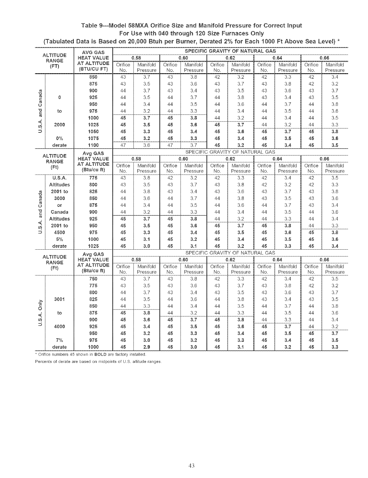
Table 9--Model 58MXA Orifice Size and Manifold Pressure for Correct Input
For Use with 040 through 120 Size Furnaces Only
(Tabulated Data is Based on 20,000 Btuh per Burner, Derated 2% for Each 1000 Ft Above Sea Level) *
ALTITUDE
RANGE
(FT)
"13 0
(3
to
r_
2000
0%
derate
ALTITUDE
RANGE
(Ft)
U.S.A.
Altitudes
200i to
=_ 3000
_3 or
Canada
r_ Altitudes
2001 to
D 4500
5%
derate
ALTITUDE
RANGE
(Ft)
>, 300t
O
<.. to
m
D 4000
7%
derate
AVG GAS
HEAT VALUE
AT ALTITUDE
(BTUiCU FT)
850
875
900
925
950
075
i000
i025
i050
i075
II00
Avg GAS
HEAT VALUE
AT ALTITUDE
(Btuicu ft)
775
800
825
850
875
000
925
950
075
i000
i025
Avg GAS
HEAT VALUE
AT ALTITUDE
(Btuicu ft)
750
775
800
825
850
875
900
025
050
075
i000
0.58
"_rifice Manifold
No. Pressure
43 3.7
43 3.5
44 3.7
44 3.5
44 3.4
44 3.2
45 3.7
45 3.5
45 3.3
45 3.2
47 3.6
0.58
Orifice Manifold
No. Pressure
43 3.8
43 3.5
44 3.8
44 3.6
44 3.4
44 3.2
45 3.7
45 3.5
45 3.3
45 3.1
45 3.0
0.58
Orifice Manifold
No. Pressure
43 3.7
43 3.5
44 3.7
44 3.5
44 3.3
45 3.8
45 3.6
45 3.4
45 3.2
45 3.0
45 2.9
SPECIFIC GRAVITY OF NATURAL GAS
0.50
Orifice Manifold
No. Pressure
43 3.8
43 3.6
43 3.4
44 3.7
44 3.5
44 3.3
45 3.8
45 3.6
45 3.4
45 3.3
47 3.7
0.52 0.54 0.65
Orifice Manifold Orifice Manifold Orifice Manifold
No. Pressure No. Pressure No. Pressure
42 3.2 42 3.3 42 3.4
43 3.7 43 3.8 42 3.2
43 3.5 43 3.6 43 3.7
44 3.8 43 3.4 43 3.5
44 3.6 44 3.7 44 3.8
44 3.4 44 3.5 44 3.6
44 3.2 44 3.4 44 3.5
45 3.7 44 3.2 44 3.3
45 3.5 45 3.7 45 3.8
45 3.4 45 3.5 45 3.5
45 3.2 45 3.4 45 3.5
SPECIFIC GRAVITY OF NATURAL GAS
0.50 0.52 0.54 0.65
Orifice Manifold Orifice Manifold Orifice Manifold Orifice Manifold
No. Pressure No. Pressure No. Pressure No. Pressure
42 3.2 42 3.3 42 3.4 42 3.5
43 3.7 43 3.8 42 3.2 42 3.3
43 3.4 43 3.6 43 3.7 43 3.8
44 3.7 44 3.8 43 3.5 43 3.6
44 3.5 44 3.6 44 3.7 43 3.4
44 3.3 44 3.4 44 3.5 44 3.6
45 3.8 44 3.2 44 3.3 44 3.4
45 3.6 45 3.7 45 3.8 44 3.3
45 3.4 45 3.5 45 3.6 45 3.8
45 3.2 45 3.4 45 3.5 45 3.5
45 3.t 45 3.2 45 3.3 45 3.4
SPECIFIC GRAVITY OF NATURAL GAS
0.50
Orifice Manifold
No. Pressure
43 3.8
43 3.6
43 3.4
44 3.6
44 3.4
44 3.2
45 3.7
45 3.5
45 3.3
45 3.2
45 3.0
0.52 0.54 0.55
Orifice Manifotd Orifice Manifotd Orifice Manifotd
No. Pressure No. Pressure No. Pressure
42 3.3 42 3.4 42 3.5
43 3.7 43 3.8 42 3.2
43 3.5 43 3.6 43 3.7
44 3.8 43 3.4 43 3.5
44 3.5 44 3.7 44 3.8
44 3.3 44 3.5 44 3.6
45 3.8 44 3.3 44 3.4
45 3.6 45 3.7 44 3.2
45 3.4 45 3.5 45 3.7
45 3.3 45 3.4 45 3.5
45 3.1 45 3.2 45 3.3
* Orifice numbers 45 shown in BOLD are factory installed
Percents of derate are based on midpoints of U.S. altitude ranges
43
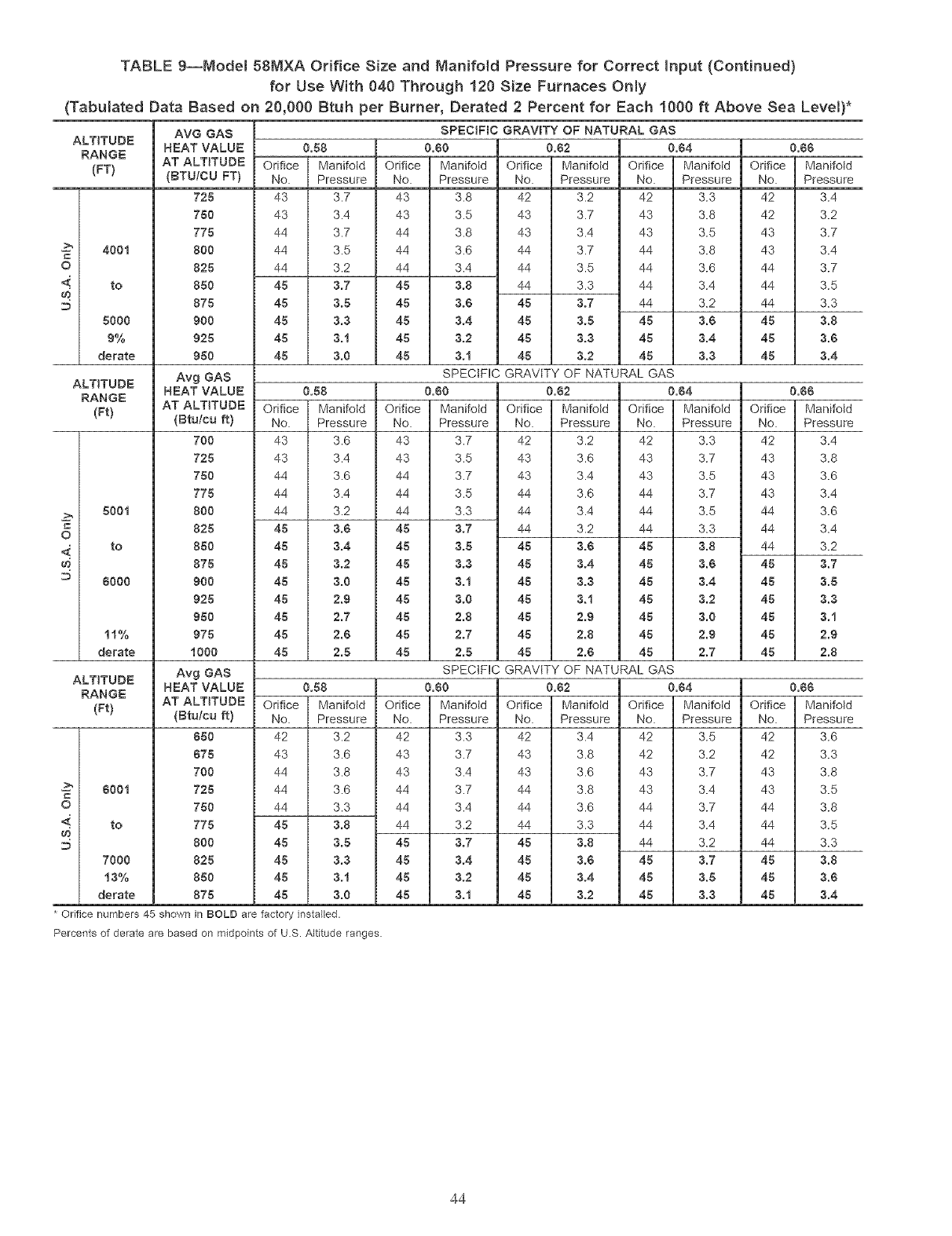
o
4
o
4
=_
o
4.
TABLE 9--Model 58MXA Orifice Size and Manifold Pressure for Correct Input (Continued)
for Use W{th 040 Through 120 Size Furnaces Only
(Tabulated Data Based on 20,000 Btuh per Burner, Derated 2 Percent for Each 1000 ft Above Sea Levem)*
ALTITUDE
RANGE
(FT)
4001
to
5000
0%
derate
ALTITUDE
RANGE
(Ft)
500t
to
8000
11%
derate
ALTITUDE
RANGE
(Ft)
600t
to
7000
13%
derate
AVG GAS
HEAT VALUE
AT ALTITUDE
(BTU/CU FT)
725
750
775
800
825
850
875
900
925
950
Avg GAS
HEAT VALUE
AT ALTITUDE
(Btuteu ft)
700
725
750
775
800
825
850
875
900
925
950
975
1000
Avg GAS
HEAT VALUE
AT ALTITUDE
(Etuteu ft)
050
075
700
725
750
775
800
825
850
875
SPECIFIC GRAVITY OF NATURAL GAg
0.58 0.60 0.62
Orifice Manifotd Orifice Manifotd Orifice Manifold
No. Pressure No. Pressure No. Pressure
43 3.7 43 3.8 42 3.2
43 3.4 43 3.5 43 3.7
44 3.7 44 3.8 43 3.4
44 3.5 44 3.6 44 3.7
44 3.2 44 3.4 44 3.5
45 3.7 45 3.8 44 3.3
45 3.5 45 3.0 45 3.7
45 3.3 45 3.4 45 3.5
45 3.1 45 3.2 45 3.3
45 3.0 45 3.t 45 3.2
0.58
Orifice Manifotd
No. Pressure
43 3.6
43 3.4
44 3.6
44 3.4
44 3.2
45 3.6
45 3.4
45 3.2
45 3.0
45 2.9
45 2.7
45 2.0
45 2.5
0.64 0.66
Orifice Manifold Orifice Manifold
No. Pressure No. Pressure
42 3.3 42 3.4
43 3.8 42 3.2
43 3.5 43 3.7
44 3.8 43 3.4
44 3.6 44 3.7
44 3.4 44 3.5
44 3.2 44 3.3
48 3.0 45 3.8
45 3.4 48 3.0
45 3.3 45 3.4
SPECIFIC GRAVITY OF NATURAL GAS
0.58
Orifice Manifold
No. Pressure
42 3.2
43 3.6
44 3.8
44 3.6
44 3.3
45 3.8
45 3.5
45 3.3
45 3.1
45 3.0
0.60 0.62
Orifice Manifold Orifice Manifold
No. Pressure No. Pressure
43 3.7 42 3.2
43 3.5 43 3.6
44 3.7 43 3.4
44 3.5 44 3.6
44 3.3 44 3.4
45 3.7 44 3.2
45 3.5 45 3.0
45 3.3 45 3.4
45 3.t 45 3.3
45 3.0 45 3.t
45 2.8 45 2.9
45 2.7 48 2.8
45 2.5 45 2.0
0.84 0.66
Orifice Manifold Orifice Manifold
No. Pressure No. Pressure
42 3.3 42 3.4
43 3.7 43 3.8
43 3.5 43 3.6
44 3.7 43 3.4
44 3.5 44 3.6
44 3.3 44 3.4
45 3.8 44 3.2
45 3.0 45 3.7
45 3.4 45 3.5
45 3.2 45 3.3
45 3.0 45 3.1
45 2,9 45 2.9
45 2,7 45 2.8
SPECIFIC GRAVITY OF NATURAL GAS
0.00 0.62
Orifice Manifold Orifice Manifold
No. Pressure No. Pressure
42 3.3 42 3.4
43 3.7 43 3.8
43 3.4 43 3.6
44 3.7 44 3.8
44 3.4 44 3.6
44 3.2 44 3.3
45 3.7 45 3.8
45 3.4 45 3.6
45 3.2 45 3.4
45 3.t 45 3.2
0.64 0.66
Orifice Manifold Orifice Manifold
No. Pressure No. Pressure
42 3.5 42 3.6
42 3.2 42 3.3
43 3.7 43 3.8
43 3.4 43 3.5
44 3.7 44 3.8
44 3.4 44 3.5
44 3.2 44 3.3
45 3.7 45 3.8
45 3.5 45 3.0
45 3.3 45 3.4
Orifice numbers 45 shown in BOLD are factory installed.
Percents of derate are based on midpoints of U.S. Altitude ranges.
44
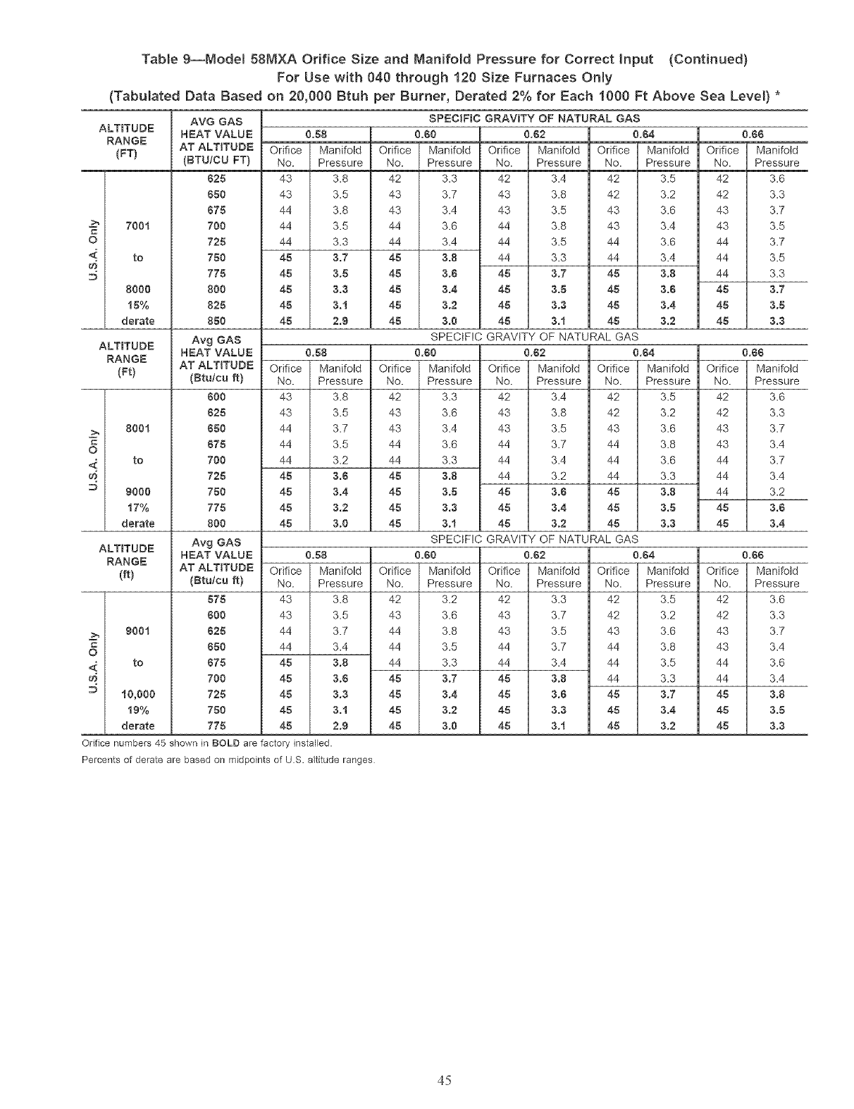
Table 9--Model 58MXA Orifice Size and Manifold Pressure for Correct Input (Continued)
For Use with 040 through 120 Size Furnaces Only
(Tabulated Data Based on 20,000 Btuh per Burner, Derated 2% for Each 1000 Ft Above Sea Level) *
ALTITUDE
RANGE
(FT)
700t
O
_ to
8000
15%
derate
ALTITUDE
RANGE
(Ft)
800t
C
o
_ to
D 9000
t7%
derate
ALTITUDE
RANGE
(ft)
900t
C
o
<.. to
D 10,000
t9%
derate
AVG GAS
HEAT VALUE
AT ALTITUDE
(BTUiCU FT)
825
650
875
7O0
725
750
775
8O0
825
850
Avg GAS
HEAT VALUE
AT ALTITUDE
(Btu/cu ft)
800
625
850
675
700
725
750
775
800
Avg GAS
HEAT VALUE
AT ALTITUDE
(Btu/cu ft)
575
600
625
650
675
700
725
750
775
0.58
Orifice Manifold
No. Pressure
43 3.8
43 3.5
44 3.8
44 3.5
44 3.3
45 3.7
45 3.5
45 3.3
45 3.1
45 2.9
0.58
Orifice Manifold
No. Pressure
43 3.8
43 3.5
44 3.7
44 3.5
44 3.2
45 3.6
45 3.4
45 3.2
45 3.0
0.58
Orifice Manifold
No. Pressure
43 3.8
43 3.5
44 3.7
44 3.4
45 3.8
45 3.6
45 3.3
45 3.1
45 2.9
SPECIFIC GRAVITY OF NATURAL GAS
0.60
Orifice Manifold
No. Pressure
42 3.3
43 3.7
43 3.4
44 3.6
44 3.4
45 3.8
45 3.8
45 3.4
45 3.2
45 3.0
0.62 0.64 0.66
Orifice Manifold Orifice Manifold Orifice Manifold
No. Pressure No. Pressure No. Pressure
42 3.4 42 3.5 42 3.6
43 3.8 42 3.2 42 3.3
43 3.5 43 3.6 43 3.7
44 3.8 43 3.4 43 3.5
44 3.5 44 3.6 44 3.7
44 3.3 44 3.4 44 3.5
45 3.7 45 3.8 44 3.3
45 3.5 45 3.5 45 3.7
45 3.3 45 3.4 45 3.5
45 3.1 45 3.2 45 3.3
SPECIFIC GRAVITY OF NATURAL GAS
0.50
Orifice Manifold
No. Pressure
42 3.3
43 3.6
43 3.4
44 3.6
44 3.3
45 3.8
45 3.5
45 3.3
45 3.1
0.62 0.64 0.65
Orifice Manifold Orifice Manifold Orifice Manifold
No. Pressure No. Pressure No. Pressure
42 3.4 42 3.5 42 3.6
43 3.8 42 3.2 42 3.3
43 3.5 43 3.6 43 3.7
44 3.7 44 3.8 43 3.4
44 3.4 44 3.6 44 3.7
44 3.2 44 3.3 44 3.4
45 3.5 45 3.8 44 3.2
45 3.4 45 3.5 45 3.5
45 3.2 45 3.3 45 3.4
SPECIFIC GRAVITY OF NATURAL GAS
0.50
Orifice Manifold
No. Pressure
42 3.2
43 3.6
44 3.8
44 3.5
44 3.3
45 3.7
45 3.4
45 3.2
45 3.0
0.62 0.64 0.55
Orifice Manifold Orifice Manifold Orifice Manifold
No. Pressure No. Pressure No. Pressure
42 3.3 42 3.5 42 3.6
43 3.7 42 3.2 42 3.3
43 3.5 43 3.6 43 3.7
44 3.7 44 3.8 43 3.4
44 3.4 44 3.5 44 3.6
45 3.8 44 3.3 44 3.4
45 3.5 45 3.7 45 3.8
45 3.3 45 3.4 45 3.5
45 3.t 45 3.2 45 3.3
Orifice numbers 45 shown in BOLD are factory installed.
Percents of derate are based on midpoints of U.S. altitude ranges
45
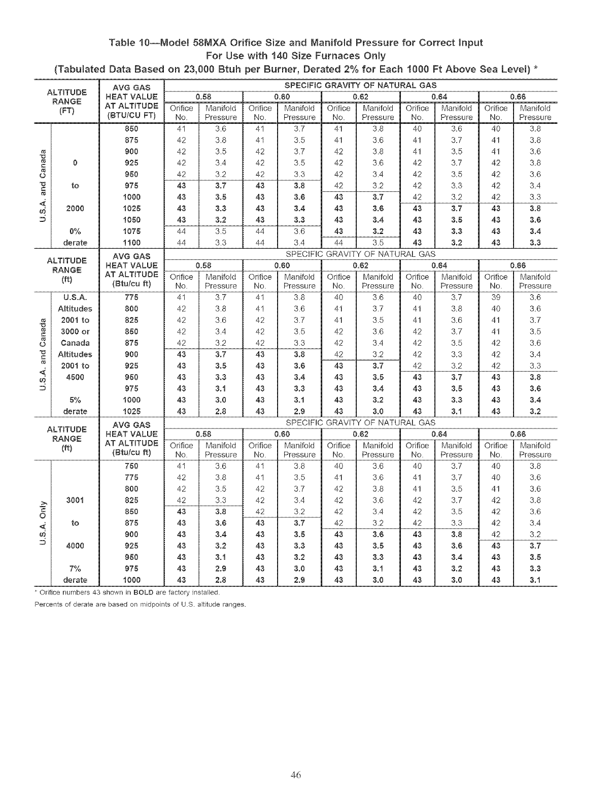
Table10--Model58tVlXAOrificeSizeand Manifold Pressure for Correct Input
For Use with 140 Size Furnaces Only
(Tabulated Data Based on 23,000 Btuh pet Burner, Detated 2"/. for Each 1000 Ft Above Sea Level) *
L)
==
8
==
C
o
ALTITUDE
RANGE
(FT)
to
2000
0%
derate
ALTITUDE
RANGE
(ft)
U.S.A.
Altitudes
2001 to
3000 or
Canada
Altitudes
2001 to
4500
5%
derate
ALTITUDE
RANGE
(ft)
300t
to
4000
7%
derate
AVG GAS
HEAT VALUE
AT ALTITUDE
(BTUiCU FT)
850
875
9O0
925
950
975
iO00
i025
i050
i075
iiO0
AVG GAS
HEAT VALUE
AT ALTITUDE
(Btutcu _)
775
800
825
850
875
900
925
950
975
iO00
i025
AVG GAS
HEAT VALUE
AT ALTITUDE
(Btulca_)
750
775
8O0
825
850
875
9O0
925
950
975
iO00
0.58
Orifice Manifold
No. Pressure
41 3.6
42 3.8
42 3.5
42 3.4
42 3.2
43 3.7
43 3.5
43 3.3
43 3.2
44 3.5
44 3.3
0.58
Orifice Manifold
No. Pressure
41 3.7
42 3.8
42 3.6
42 3.4
42 3.2
43 3.7
43 3.5
43 3.3
43 3.i
43 3.0
43 2.8
SPECIFIC GRAVITY OF NATURAL GAS
0.50 0.82
Orifice Manifold Orifice Manifold
No. Pressure No. Pressure
41 3.7 41 3.8
41 3.5 41 3.6
42 3.7 42 3.8
42 3.5 42 3.6
42 3.3 42 3.4
43 3.8 42 3.2
43 3.5 43 3.7
43 3.4 43 3.5
43 3.3 43 3.4
44 3.5 43 3.2
44 3.4 44 3.5
0.64 0.65
Orifice Mani_Id Orifice Manifold
No. Pressure No. Pressure
40 3.6 40 3.8
41 3.7 41 3.8
41 3.5 41 3.6
42 3.7 42 3.8
42 3.5 42 3.6
42 3.3 42 3.4
42 3.2 42 3.3
43 3.7 43 3.8
43 3.5 43 3.5
43 3.3 43 3.4
43 3.2 43 3.3
SPECIFIC GRAVtTY OF NATURAL GAS
0.50 0.52
Orifice Manifotd Orifice Manifold
No. Pressure No. Pressure
41 3.8 40 3.6
41 3.6 41 3.7
42 3.7 41 3.5
42 3.5 42 3.6
42 3.3 42 3.4
43 3,8 42 3.2
43 3.5 43 3.7
43 3.4 43 3.5
43 3.3 43 3.4
43 3.1 43 3.2
43 2.9 43 3.0
0.54 0.65
Orifice Manifold Orifice Manifold
No. Pressure No. Pressure
40 3.7 39 3.6
41 3.8 40 3.6
41 3.6 41 3.7
42 3.7 41 3.5
42 3.5 42 3.6
42 3.3 42 3.4
42 3.2 42 3.3
43 3.7 43 3.8
43 3.5 43 3.5
43 3.3 43 3.4
43 3.1 43 3.2
SPECIFIC GRAVtTY OF NATURAL GAS
0.58 0.50 0.52
Orifice Manifold Orifice Manifotd Orifice Manifotd
No. Pressure No. Pressure No. Pressure
41 3.6 41 3.8 40 3.6
42 3.8 41 3.5 41 3.6
42 3.5 42 3.7 42 3.8
42 3.3 42 3.4 42 3.6
43 3.8 42 3.2 42 3.4
43 3.5 43 3.7 42 3.2
43 3.4 43 3.5 43 3.5
43 3.2 43 3.3 43 3.5
43 3.t 43 3.2 43 3.3
43 2.9 43 3.0 43 3.1
43 2.8 43 2.9 43 3.0
0.64 0.55
Orifice Mani_Id Orifice Mani_Id
No. Pressure No. Pressure
40 3.7 40 3.8
41 3.7 40 3.6
41 3.5 41 3.6
42 3.7 42 3.8
42 3.5 42 3.6
42 3.3 42 3.4
43 3.8 42 3.2
43 3.5 45 3.7
43 3.4 43 3.5
43 3.2 43 3.3
43 3.0 43 3.1
Orifice numbers 43 shown in BOLD are factory installed.
Percents of derate are based on midpoints of U.S. altitude ranges.
4d
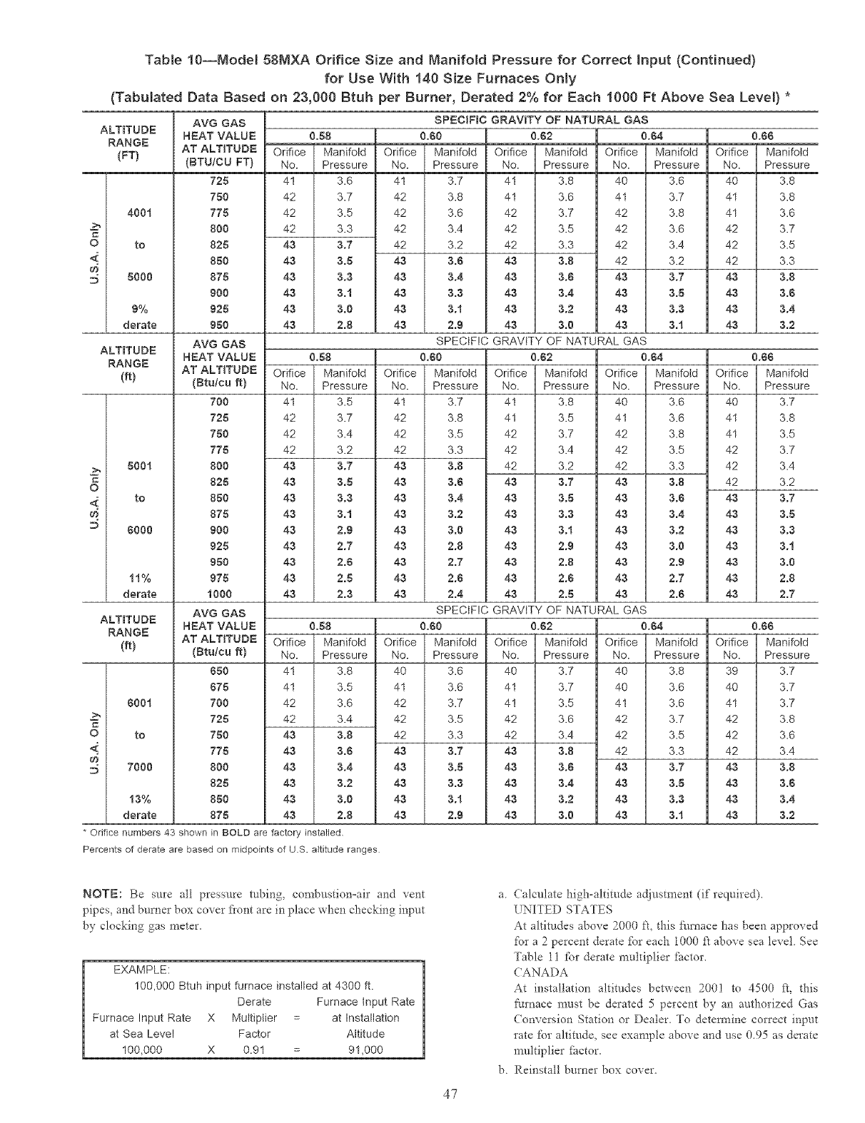
Table 10--Model 58M×A Orifice Size and NaNfold Pressure for Correct input (Continued)
for Use With 140 Size Furnaces Only
(Tabulated Data Based on 23,000 Btuh per Burner, Derated 2"/. for Each 1000 Ft Above Sea Level) *
ALTITUDE
RANGE
(FT)
4001
C
o to
d}
:5 5000
9%
derate
ALTITUDE
RANGE
(ft)
500t
C
o
to
D$000
11%
derate
ALTITUDE
RANGE
(ft)
6001
C
o to
d} 7000
13%
derate
AVG GAS
HEAT VALUE
AT ALTITUDE
(BTU/CU FT)
725
750
775
800
825
850
875
900
925
950
AVG GAS
HEAT VALUE
AT ALTITUDE
(Btu/cu ft)
700
725
750
775
800
825
850
875
900
925
950
975
1000
AVG GAS
HEAT VALUE
AT ALTITUDE
(Btu/cu ft)
850
675
700
725
750
775
800
825
850
875
0.58
'_rifice Manifold
No. Pressure
41 3.6
42 3.7
42 3.5
42 3.3
43 3,7
43 3.5
43 3.3
43 3.1
43 3.0
43 2.8
0.58
Orifice Manifold
No. Pressure
41 3.5
42 3.7
42 3.4
42 3.2
43 3,7
43 3.5
43 3,3
43 3.1
43 2.9
43 2.7
43 2.6
43 2.8
43 2.3
0.58
Orifice Manifold
No. Pressure
4I 3.8
41 3.5
42 3.6
42 3.4
43 3.8
43 3.6
43 3.4
43 3.2
43 3.0
43 2.8
SPECIFIC GRAVITY OF NATURAL GAS
0.00
Orifice Manifold
No. Pressure
41 3.7
42 3.8
42 3.6
42 3.4
42 3.2
43 3.6
43 3.4
43 3.3
43 3.1
43 2.9
0.62 0.64 0.66
Orifice Manifold Orifice Manifold Orifice Manifold
No. Pressure No. Pressure No. Pressure
4I 3.8 40 3.6 40 3.8
41 3.6 41 3.7 41 3.8
42 3.7 42 3.8 41 3.6
42 3.5 42 3.6 42 3.7
42 3.3 42 3.4 42 3.5
43 3,8 42 3.2 42 3.3
43 3.$ 43 3.7 43 3.8
43 3.4 43 3.5 43 3.6
43 3.2 43 3.3 43 3.4
43 3.0 43 3.t 43 3.2
SPECIFIC GRAVITY OF NATURAL GAS
0.60 0.62 0.64 0.66
Orifice Manifold Orifice Manifold Orifice Manifold Orifice Manifold
No. Pressure No. Pressure No. Pressure No. Pressure
41 3.7 41 3.8 40 3.6 40 3.7
42 3.8 41 3.5 41 3.6 41 3.8
42 3.5 42 3.7 42 3.8 41 3.5
42 3.3 42 3.4 42 3.5 42 3.7
43 3,8 42 3.2 42 3.3 42 3.4
43 3.0 43 3,7 43 3,8 42 3.2
43 3.4 43 3.5 43 3.8 43 3.7
43 3.2 43 3.3 43 3.4 43 3.5
43 3.0 43 3.t 43 3.2 43 3.3
43 2.8 43 2.9 43 3.0 43 3.t
43 2.7 43 2.8 43 2.9 43 3.0
43 2.6 43 2.6 43 2.7 43 2.8
43 2.4 43 2.5 43 2.0 43 2.7
SPECIFIC GRAVITY OF NATURAL GAS
0.60
Orifice Manifold
No. Pressure
40 3.6
41 3.6
42 3.7
42 3.5
42 3.3
43 3.7
43 3.5
43 3.3
43 3.t
43 2.9
0.62 0.64 0.66
Orifice Manifold Orifice Manifold Orifice Manifold
No. Pressure No. Pressure No. Pressure
40 3.7 40 3.8 39 3.7
41 3.7 40 3.6 40 3.7
41 3.5 41 3.6 41 3.7
42 3.6 42 3.7 42 3.8
42 3.4 42 3.5 42 3.6
43 3.8 42 3.3 42 3.4
43 3.6 43 3.7 43 3.8
43 3.4 43 3.5 43 3.6
43 3.2 43 3.3 43 3.4
43 3.0 43 3.t 43 3.2
* Orifice numbers 43 shown in BOLD are factory installed
Percents of derate are based on midpoints of U.S. altitude ranges
NOTE: Be sure all pressure robing, con_bustion-air and vent
pipes, and burner box cover flont are in place when checking input
by clocking gas meter.
EXAMPLE:
100,000 Btuh input furnace installed at 4300 ft.
Derate Furnace input Rate
Furnace Input Rate X Multiplier at Installation
at Sea Level Factor Altitude
100,000 X 0.91 91,000
47
a. Calcnlate high-altitude adjustment (if required).
UNITED STATES
At altitudes above 2000 fk this _hmace has been approved
for a 2percent derate for each 1000 f_ above sea level See
Table 11 for derate multiplier _ctor.
CANADA
At installation altitudes between 2001 to 4500 ft, this
furnace must be derated 5 percent by an authorized Gas
Conversion Station or Dealer. To determine correct input
rate for altimdQ see example above and use 0.95 as derate
multiplier _hctor.
b. Reinstall burner box cover.
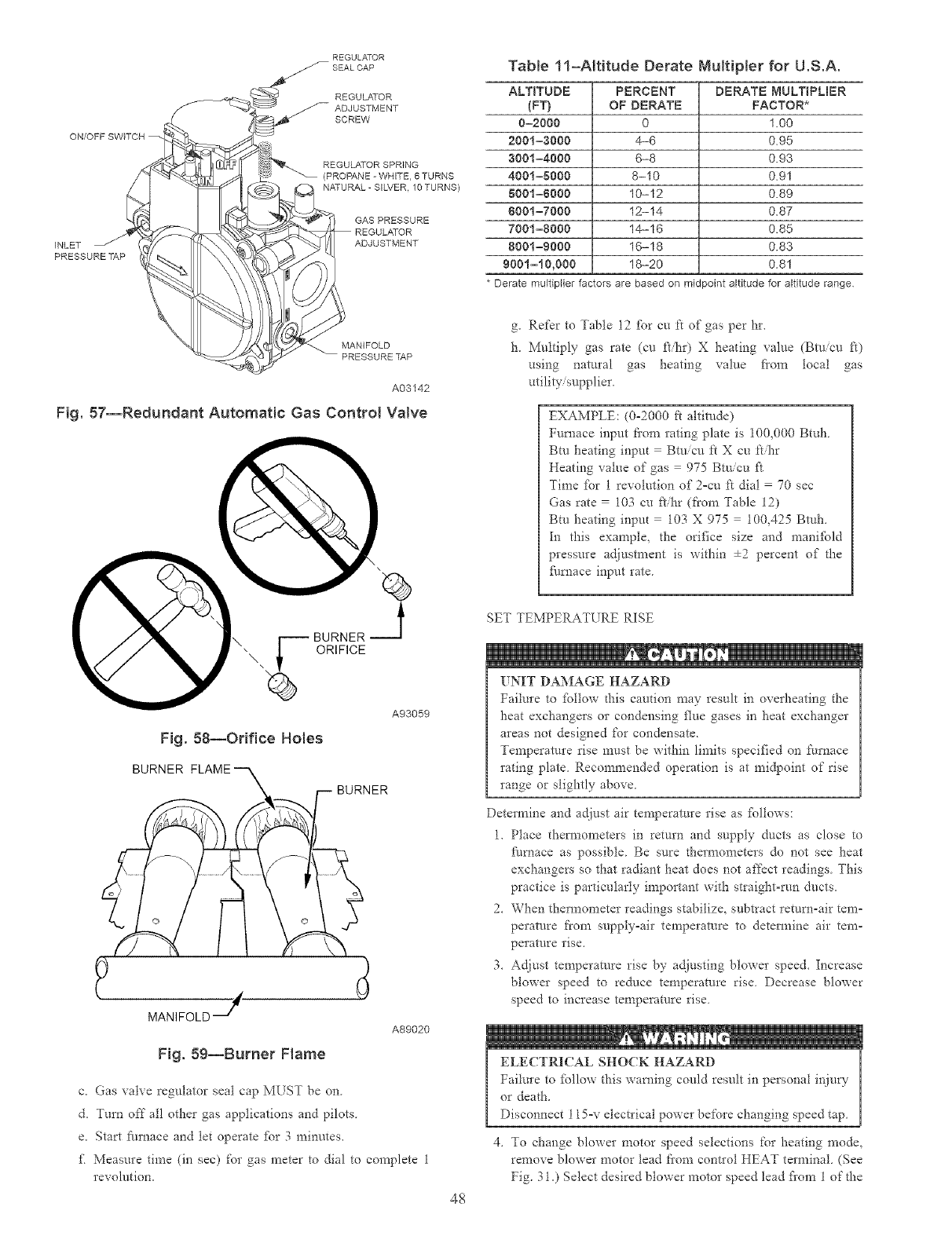
REGULATOR Tab{e 11-ARRude Derate MuRipler for U.S.A.
ON/OFF SWITCH
INLET
PRESSURE TAP
REGULATOR
ADJUSTMENT
SCREW
REGULATOR SPRING
(PROPANE - WHITE 6 TURNS
NATURAL -SILVER, 10 TURNS)
GAS PRESSURE
REGULATOR
ADJUSTMENT
ALTITUDE PERCENT
(FT} OF DERATE
0=2000 0
2001=3000 4-6
3001 =4000 6-8
4001=8000 8-10
8001=6000 10-12
6001=7000 12-14
7001=8000 14-16
8001=9000 16-18
9001=t0,000 18-20
* Derate multiplier factors are based on midpoint altitude
BERATE MULTIPUER
FACTOR*
1.00
0.95
0.93
0.91
0.89
0.87
0.85
0.83
0.81
for altitude range
MANIFOLD
PRESSURE TAP
A03142
Fig. 87--Redundant Automatic Gas Control Valve
\
--BURNER J
ORIFICE
Fig. 88--Orifice Holes
BURNER FLAME J_
f_ FBURNER
MANIFOLD J
Fig. 59--Burner Flame
A93059
A89020
c. Gas valve regulator seal cap MIST be on
d. Turn off all other gas applications and pilots
e. Start fi/rnace and let operate _br 3 minutes.
£ Measure time (in sec) for gas meter to dial to complete 1
revolution,
g. Refer to Table 12 %r cu ft of gas per hr.
h. Multiply gas rate (cu fl&r) X heating value (Bmicu ft)
using natural gas heating value fiom local gas
utility/supplier.
EXAMPLE: (0=2000 ft altitude)
Furnace input t)om rating plate is 100,000 Btuh.
Bm heating input Bmicu ft X cu fthr
Heating value of gas 975 Btuicu _l
Time _br 1 revolution of 2=cu ft dial 70 sec
Gas rate 103 cu ft&r (from Table 12)
Btu heating input 103 X 975 100,425 Bmh.
In this example, the orifice size and manifbld
pressure adjustment is within ÷2 percent of the
_;arnace input rate
48
SET TEMPERATURE RISE
UNIT DAMAGE HAZARD
Failure to fbllow d_is caudon may result in overheating the
heat exchangers or condensing flue gases in heat exchanger
areas not designed for condensate.
Temperature rise must be within limits specified on t:urnace
rating plate. Recommended operation is at mi@oint of rise
range or slightly above.
Determine and adjust air temperature rise as _bllows:
1. Place them_ometers in return and supply ducts as close to
f_ultace as possible Be sure thermometers do not see heat
exchangers so that radiant heat does not affect readings This
practice is particularly important with straight=run ducts.
2. When thermometer readings stabilize, subtract return-air tem-
perature from supply=air temperature to detemaine air tem-
perature rise.
3. Adjust temperature rise by adjusting blower speed. Increase
blower speed to reduce temperature rise. Decrease blower
speed to increase temperature rise.
ELECTRICAL SHOCK HAZARD
Failm'e to _Bllow this warning could result in personal in3u W
or death.
Disconnect 115=v electrical power before changing speed tap.
4. To change blower motor speed selections for heating mode,
remove blower motor lead fiom control HEAT terminal. (See
Fig. 31.) Select desired blower motor speed lead fi'om 1 of the
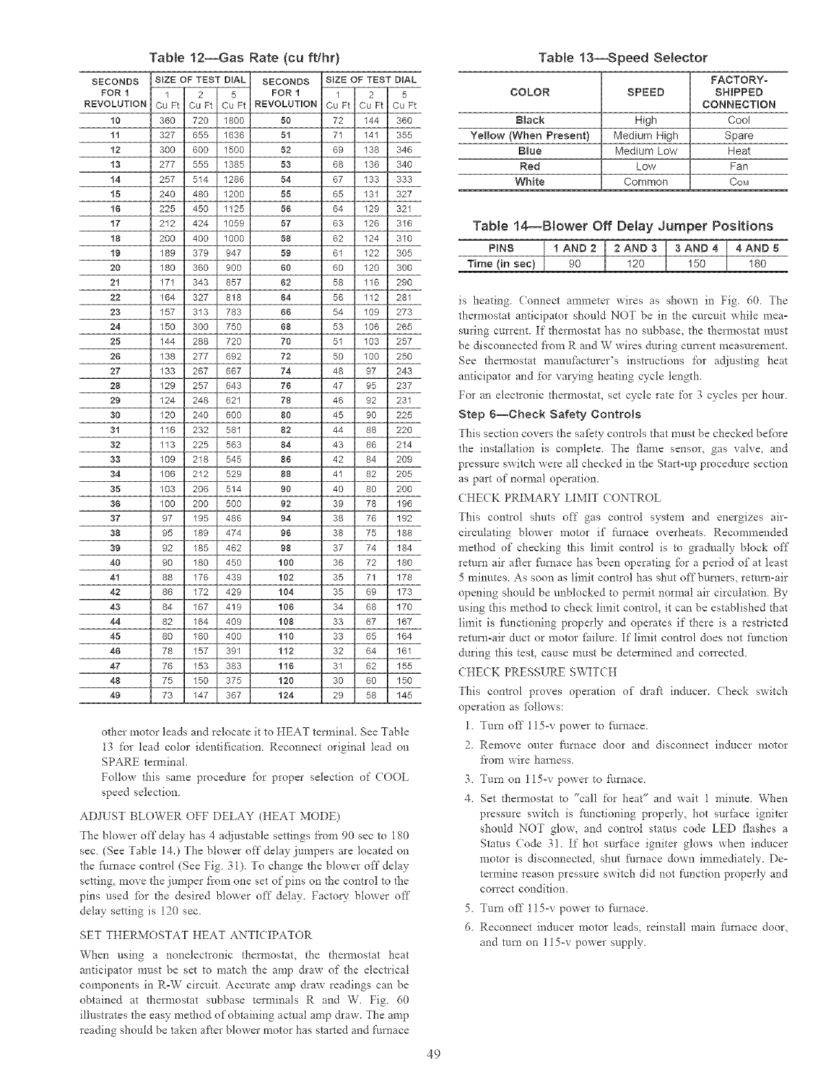
Table 12--Gas Rate (cu ft/hr}
SECONDS SIZE OF TEST DIAL SECONDS SIZE OF TEST DIAL
FOR 1 1 2 5 FOR 1 1 2 5
REVOLUTION Cu Ft Cu Ft Cu Ft REVOLUTION Cu Ft Cu Ft Cu Ft
10 360 720 1800 50 72 144 360
11 327 655 1636 51 71 141 355
12 300 600 1500 52 69 138 346
13 277 555 1385 53 68 136 340
14 257 514 1286 54 67 133 333
15 240 480 1200 55 65 131 327
16 225 450 1125 56 64 129 321
17 212 424 1059 57 63 126 316
18 200 400 1000 58 62 124 310
19 189 379 947 59 61 122 305
20 180 360 900 60 60 120 300
21 171 343 857 62 58 116 290
22 164 327 818 64 56 112 281
23 157 313 783 66 54 109 273
24 150 300 750 68 53 106 265
25 144 288 720 70 51 103 257
26 138 277 692 72 50 100 250
27 133 267 667 74 48 97 243
28 129 257 643 76 47 95 237
29 124 248 621 78 46 92 231
30 120 240 600 80 45 90 225
31 116 232 581 82 44 88 220
32 113 225 563 84 43 86 214
33 109 218 545 86 42 84 209
34 106 212 529 88 41 82 205
35 103 206 514 80 40 80 200
38 100 200 500 82 39 78 196
37 97 195 486 84 38 76 192
88 95 189 474 96 38 75 188
36 92 185 462 98 37 74 184
40 90 180 450 108 36 72 180
41 88 176 439 102 35 71 178
42 86 172 429 104 35 69 173
43 84 167 419 106 34 68 170
44 82 164 409 108 33 67 167
45 80 160 400 110 33 65 164
48 78 157 391 112 32 64 161
47 76 153 383 116 31 62 155
48 75 150 375 120 30 60 150
49 73 147 367 124 29 58 145
other motor leads and relocate it to HEAT tem_inaL See Table
13 for lead color identification. Reconnect original lead on
SPARE tem_inal.
Follow this same procedure fbr proper selection of COOL
speed selection.
ADJUST BLOWER OFF DELAY (HEAT MODE)
The blower off delay has 4 adjustable settings tkem 90 sec to 180
sec (See Table 14.) The blower off delay jumpers are located on
the ft/mace control (See Fig 31). To change the blower off delay
setdng, move the jumper fi'om one set of pins on the control to the
pins used [br the desired blower off delay. Factory blower off
delay setting is 120 sec.
SET THERMOSTAT HEAT ANTICIPATOR
When using a nonelectronic them_ostat, the them_ostat heat
anticipator must be set to match the amp &aw of the electrical
components in R-W circuit. Accurate amp draw readings can be
obtained at them_ostat subbase terminals R and W. Fig 60
illustrates the easy method of obtaining actual amp &aw. The amp
reading should be taken after blower motor has started and furnace
Table 13--Speed Selector
FACTORY-
COLOR SPEED SH_PPED
CONNECTION
B_ack High Cool
Yellow (When Present} Medium High Spare
B_ue Medium Low Heat
Red Low Fan
White Common COM
Table 14_Biower Off Delay Jumper Positions
PINS ,AND2 12AND3 I 3AND4 [ 4AND5
Time (in sec) 90 120 150 180
is heating. (onnect ammeter wires as shown in Fig. 60 The
thermostat anticipator should NOT be in the curcuit while mea=
suring current. If them_ostat has no subbase, the thermostat must
be disconnected flora R and W wires during CUITent measurement.
See them_ostat manufi_cturer's instrnctions t'or adjusting heat
anticipator and for yawing heating cycle length.
For an electronic thermostat_ set cycle rate for 3 cycles per hour.
Step 6--Check Safety Controls
This section covers the safety controls that must be checked befbre
the installation is complete. The flame sensor, gas valve, and
pressure switch were all checked in the Start-up procedure section
as part of normal operation.
CHE(K PRIMARY LIMIT CONTROL
This control shuts off gas control system and energizes alp
circulating blower motor if furnace overheats. Recommended
method of checking this limit control is to gradually block off
return air after ftlmace has been operating fc_r a period of at least
5 minutes. As soon as limit control has shut offbumers, return=air
opening should be unblocked to pem_it normal air circulation. By
using this method to check limit control, it can be established that
limit is functioning properly and operates if there is a restricted
return=air duct or motor _hilure. If limit control does not function
during this test, cause must be determined and corrected.
CHECK PRESSURE SWITCH
This control proves operation of draft inducer. Check switch
operation as fbllows:
1. Turn off l15=v power to fi/mace.
2. Remove outer _arnace door and disconnect inducer motor
fi'om wire harness.
3. Turn on 115=v power to furnace.
4. Set d-_ennostat to "call for heat" and wait 1 minute. When
pressure switch is ftmctioning properly, hot surface igniter
should NOT glow, and control status code LED flashes a
Status Code 31. If hot surface igniter glows when inducer
motor is disconnected, shut ft/mace down immediately. De-
termine reason pressure switch did not flmction properly and
correct condition.
5. Tufa off l15=v power to fi/mace.
(5. Reconnect inducer motor leads, reinstall main furnace door,
and tara on 115=v power supply.
49
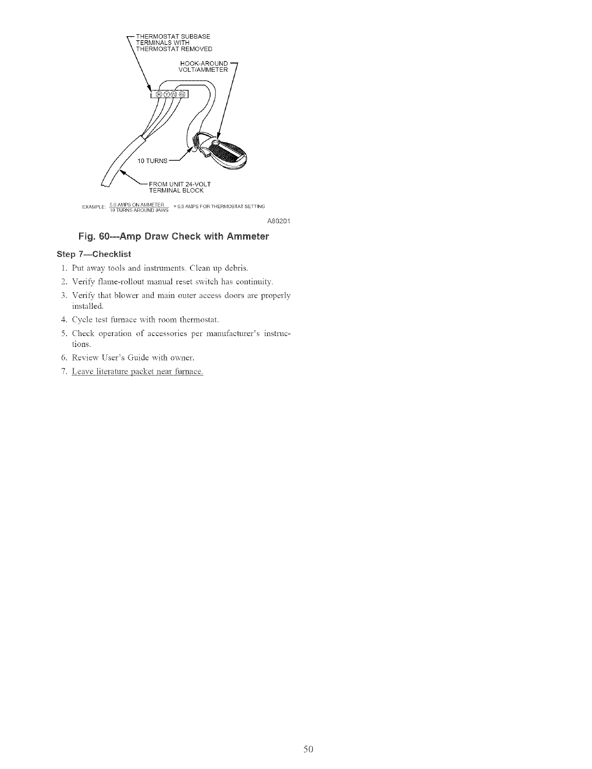
TERMINALS WiTH
THERMOSTAT REMOVED
FROM UNIT 24-VOLT
TERMINAL BLOCK
EXAMPLE 5 0 AMPS ON AMMETER = 0 5 AMPS FOR THERMOSTAT SETTING
l0 TURNS AROUND JAWS
A80201
Fig. 60--Amp Draw Check wRh Ammeter
Step 7--Checklist
l, Pot away tools and instruments Clean up debris
2, Verify flame=roliout manual reset s_itch has continuity
3, Ve*it}- that blower and main outer access doors are properly
installed.
4. (ycle test furnace x_ith room thermostat.
5. (heck operation of accessories per manui:acturer's inst,/c=
tions,
6. Review Users Guide _ith owner.
7. Leave literature packet near fhrnace.
5O
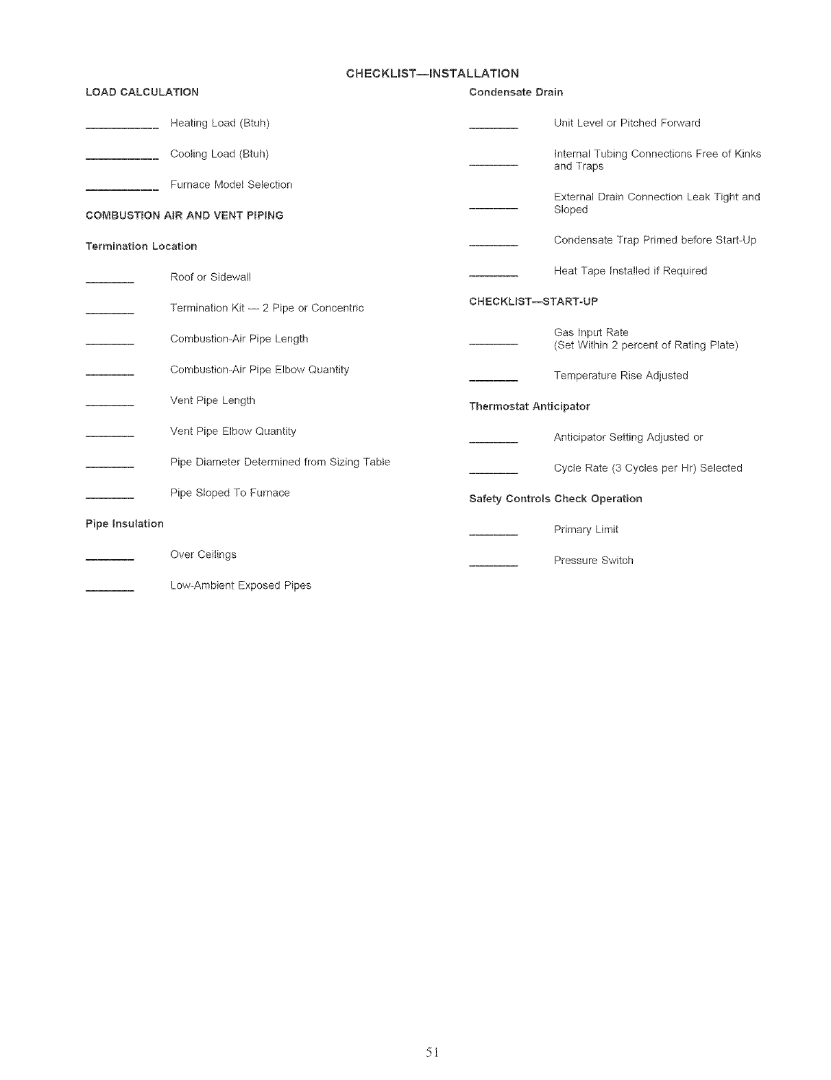
LOAD CALCULATION
CH ECKMST--INSTALLATION
Condensate Drain
Heating Load (Btuh)
Cooling Load (Btuh)
Furnace ModeJ Selection
COMBUSTION AiR AND VENT PIPING
Termination Location
Roof or Sidewall
Termination Kit -- 2 Pipe or Concentric
Combustion-Air Pipe Length
Combustion-Air Pipe Elbow Quantity
Vent Pipe Length
Vent Pipe Elbow Quantity
Pipe Diameter Determined from Sizing Table
Pipe Sloped To Furnace
Pipe insulation
Over CeiJings
Unit Level or Pitched Forward
internal Tubing Connections Free of Kinks
and Traps
External Drain Connection Leak Tight and
Sloped
Condensate Trap Primed before Start-Up
Heat Tape installed if Required
CHECKLIST--START-UP
Gas input Rate
(Set Within 2 percent of Rating Plate)
Temperature Rise Adjusted
Thermostat Anticipator
Anticipator Setting Adjusted or
Cycle Rate (3 Cycles per Hr) Selected
Safety Controls Cheek Operation
Primary Limit
Pressure Switch
Low-Ambient Exposed Pipes
5i

Copyright 2005 CARRIER Corp., 7310 W. Morris St • Indianapolis, IN 46231 58mxa18si
Manufacturer reserves the right to discontinue, or change at any time, specifications or designs without notice and without incurring obligations,
B°°kLL_. PC 101 Catalog No 535-80157 Pd_ted in U.S.A. Form 58MXA-18SI Pg 52 2-05 Replaces: 58MXA-17SI
Tab 16al 8a
