CARRIER Furnace/Heater, Gas Manual L0503421
User Manual: CARRIER CARRIER Furnace/Heater, Gas Manual CARRIER Furnace/Heater, Gas Owner's Manual, CARRIER Furnace/Heater, Gas installation guides
Open the PDF directly: View PDF ![]() .
.
Page Count: 32
Installation Instructions
Gas Conversion Kit Natural-to-Propane for
All Condensing Furnaces, 2-Stage 80%
Variable Speed, 2-Stage Non-Condensing
and Fixed Capacity 80% Furnaces
KGANP3001ALL
NOTE: Read the entire instlq./ction manual before starting the installation
This symbol --> indicates a change since the tast issue,
SAFETY CONSIDERATIONS
Installing and servicing heating equipment can be hazardous dne to gas and electrical components Only trained and qualified personnel shontd
install, repair, or service heating equipment.
Untrained personnel can perform basic maintenance Jimctions such as cleaning and replacing air filters. Trained service personnel must pertbm_
all other operations When working on heating equipmenk observe precautions in the literature, on tags, and on labels attached to or shipped with
the unit, and other sa_ty precautions that may apply.
Follow all safety codes. In the United States, follow all safety codes including the National Fuel Gas (?ode (NFGC) NFPA No. 54°2002 ANSI
Z223. I°2002. In Canada, refer to the National Standard of Canada, Natural Gas and Propane Installation (?odes (NSCNGPIC), CANiCGA-B 149. I
and 2-M00.
Wear safety glasses and work gloves. Have a fire extinguisher available during Start°up, Adjustment steps, and service calls.
Recognize sa_?ty in_brrnation. This is the safety-alert symbol z_ " When you see this symbol on the Nmace and in instructions or manuals, be
alert to the potential for personal inju W
Understand the signal words DANGER, WARNING, (AUTION, and NOTE The words DANGER, WARNING, and CAL TION are used with
the safety-alert symbol DANGER identities the most serious hazards, which will result in severe personal injury or death. WARNING signifies
hazards, which could result in personal ir!iury or death. CAUTION is used to identify unsafe practices, which may result in minor personal injury,
or product and property damage. NOTE is used to highlight suggestions, which will result in enhanced installation, reliability, or operation.
Z_ WARNmNG: FIRE, EXPLOS{ON, ELECTRICAL SHOCK, AND CARBON MONOXIDE POISONmNG HAZARD
This conversion kit shall be installed by a qualified service agency in accordance with the manufacturer's instructions and all applicable
codes and requirements of the authority having jurisdiction. If the information in these instructions is not followed exactly, a fire,
explosion, or production of carbon monoxide may result causing property damage, personal injury, or loss of life. The qualified service
agency is responsible for the proper installation of this furnace with this kit The installation is not proper and complete until the
operation of the converted appliance is checked as specified in the manufacturer's instructions supplied with the kit.
Z_ AVERTISSEMENT: LE FEU, L'EXPLOSION, CHOC ELECTRIQUE ,ET MONOXYDE DE CARBONEi EMPOISONNER
Cette trousse de conversion ne doit 6tre installee que par le representant d'un organisme qualifie et conformement aux instructions
du fabricant eta tousles codes et exigences pertinents de I'autorite competente. Les instructions du present guide doivent 6tre suivies
afin de reduire au minimum au risque d'incendie ou d'explosion de dommange materiels, de blessure ou de mort. L'organisme qualifie
responsable de !'installation adequate de cette trousse. L'insta!lation n'est pas adequate ni complete tant que le bon fonctionnement
de I'appereil converti n'a pas et6 verfi6 se!on les instructions du fabricant fornies avec la trousse.
BNTRODUCTION
--> This instruction covers the installation of gas conversion kit Part No. KGANP3001 ALL to convert the following I:urnaces fi'om natural gas usage
to propane gas nsage. See appropriate section for your l'umace type
* Section 1= (Page 3) Models 58STA, 58STX, 58DLA, 58DLX, 310AAV, 310JAV, 311AAV, 311JAV, PGSMAA, PGSJAA, 58CTA, 58CTX,
58CVA, 58CVX, 312AAV, 312JAV, 315AAV, 315JAV 33.3°inch high, Indnced°( ombustion, Hot-Surti_ce Ignition, Single Stage, 2-Stage and
Variable Speed Non=Condensing 4°Way Mulfipoise Furnaces with 42,000 through 154,000 Bmh gas input rates.
Form: AG-GANP-31 Cancels: AG-GANP-30 Printed in U.S.A. 5-04 Catalog No. 63GA-NP11
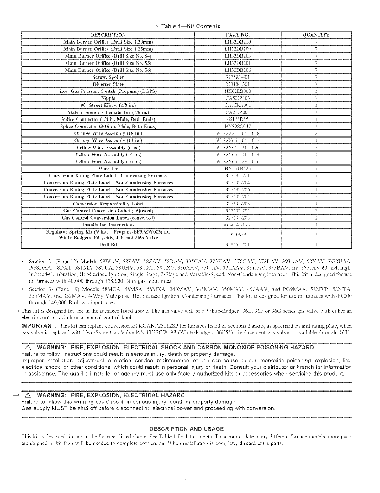
Tablel--Kit Contents
DESCRIPTION
Main Burner Orifice (Drill Size 1.30ram)
Main Burner Orifice (Drill Size 1.25mru)
Main Burner Orifice (Drill Size No. 54)
Main Burner Orifice (Drill Size No. 55)
Main Burner Orifice (Drill Size No. 56)
Screw, Spoiler
Diverter Plate
Low Gas Pressure Switch (Propane) (LGPS)
Nipple
90° Street Elbm_ (1/8 in.)
Male x Female x Female Tee (1/8 in.)
Spike Connector (1/4 in. Male, Both Ends)
Spike Connector (3/16 in. Male, Both Ends)
Orange Wire Assembly (I8 in.)
Orange Wire Assembly (12 ill.)
Yellow Wire Assembly (6 in.)
Yellow Wire Assembly (14 ill.)
Yellow Wire Assembly (16 ill.)
Wire Tie
Conversion Rating Plate Label--Condensing Furnaces
Conversion Rating Plate Label--Nun-(ondensing Furnaces
Conversion Rating Plate Label--Nun-Condensing Furnaces
Conversion Rating Plate Labd--Nun-(ondensing Furnaces
Conversion Responsibility Label
Gas Control Conversion Label (adjusted)
Gas Control Conversion Label (converted)
Installation Instructions
Regulator Spring Kit ('_'_hite--Propane-EF39ZW023) Nr
White-Rodgers 36(, 36E, 36F and 36G Valve
Drill Bit
PART NO. Q[ ANTITY
LH32DB210 7
LH32DB209 7
LH32DB203 7
LH32DB201 7
LH32DB206 7
327593-401 7
323184-301 1
HK02LB008 1
(A52JZI03 1
CA 15P-_001 1
(A21JZ001 1
66175D55 1
HY89S(047 1
W182X23- -04- -018 2
W182X66- -04- -012 1
W182Y6(> -11- -006 1
W182Y66- -11- -014 1
W182Y66- -23- -016 1
HY76TB125 1
327697-201 1
327697-204 1
327697-206 1
327697-204 1
327697-205 1
327697-202 1
327697-203 1
AG-GANP-31 1
92-0659 2
328456-401 1
Section 2= (Page 12) Models 58WAV, 58PAV, 58ZAV, 58RAV, 395CAV, 383KAV, 376(AV, 373LAV, 393AAV, 58YAV, PGSUAA,
PGSDAA, 58DXT. 58TMA. 58TUA. 58UHV. 58UXT, 58UXV. 330AAV, ._ 0JAV. 33 IAAV, 3._1JAV, 333BAV, and 3_3JA'v 40=Inch high,
Induced-Combustion, Hot=Surface Ignition, Single Stage, 2-Stage and Variable-Speed, Non-Condensing Furnaces This kit is designed fur use
in _hmaces _itl", 40,000 through 154,000 Btuh gas input rates.
Section 3- (Page 19) Models 58MCA, 58MSA, 58MXA, 340MAV, 345MAV, 350MAV, 490AAV, arid PG9MAA, 58MVP, 58MTA,
355MAV, and 352MAV, 4-Way Multipoise, Hot Surface Ignition, ( ondensing Furnaces This kit is designed _br use in furnaces xxith 40,000
through 140,000 Bmh gas input rates.
--> This kit is designed fur use in the fi_rnaces listed abo\e. The gas valve will be a White-Rodgers 36E, ._6F or _6G series _as valve with either an
electric control switch or a manual contlol knob.
iMPORTANT: This kit can replace conversion kit KGANP25012SP fur _i/rnaces listed in Sections 2and 3, as specified on unit rating plate, when
gas xalve is replaced with Two-Stage Gas Valxe PN EF33(WI98 (White=Rodgers 36E55) Replacement gas xalxe is a_ailable through RCD.
Z_ WARNmNG: FIRE, EXPLOSION, ELECTRICAL SHOCK AND CARBON MONOXIDE POISONING HAZARD
Failure to follow instructions could result in serious injury, death or property damage.
Improper installation, adjustment, alteration, service, maintenance, or use can cause carbon monoxide poisoning, explosion, fire,
electrical shock, or other conditions, which could result in personal injury or death. Consult your distributor or branch for information
or assistance. The qualified installer or agency must use only factory-authorized kits or accessories when servicing this product.
--> Z_ WARNING: FIRE, EXPLOSION, ELECTRICAL HAZARD
Failure to follow this warning could result in serious injury, death or property damage.
Gas supply MUST be shut off before disconnecting electrical power and proceeding with conversion.
DESCRIPTION AND USAGE
This kit is designed %r use in the [:umaces listed above. See Table 1%r kit contents. To accommodate many different furnace models, more parts
are shipped in kit than will be needed to complete conxersion. When installation is complete, discard extra parts
2
INSTALLATION
SECTION1-INDUCED-COMB[STION,HOT-S[RFACE IGNITION, SINGLE-STAGE, TWO-STAGE AND VARIABLE-SPEED,
33.3-IN(H HIGH, NON-(ONDENSING F! RNACES
SINGLE STAGE MODELS 2-STAGE MODELS VARIABLE SPEED MODELS
58STA 310AAV PGSMAA 5SCTA 312AAV 58(VA 315AAV
58DLA 311AAV PG8JAA 58CTX 312JAV 58(VX 315JAV
58STX 310JAV
58DLX 311JAV
PROCEDURE I--INSTALL MAiN BURNER ORIFICES AND gUNNER SPOILER SCREWS
NOTE: See Fig. 2 for component location in UPFLOW orientation. Reorient component arrangement when fl/mace is installed in other positions,
-5 z:_ CAUTION: UNIT DAMAGE HAZARD
Failure to follow this caution may result in excessive burner noise and misdirection of burner flames, This may result in flame
impingement of the burners and the heat exchangers, causing failures.
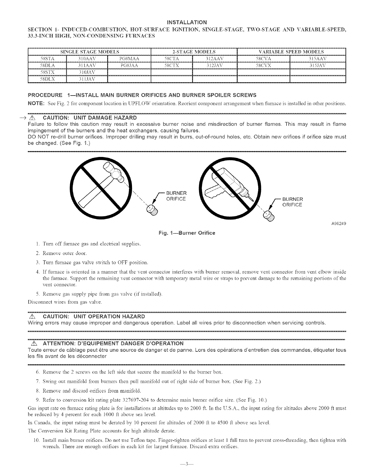
DO NOT re-drill burner orifices, Improper drilling may result in burrs, out-oforound holes, etc, Obtain new orifices if orifice size must
be changed. (See Fig. 1.)
\_-- BURNER
\ORIFICE
1. Trim off fllrnace gas and electrical supplies.
2. Remove onter door.
3 Turn furnace gas valve switch to OFF position.
Fig, l--Burner Orifice
BURNER
ORIFICE
A96249
4. If furnace is oriented in a manner that the vent connector inter_)res with burner removal, remove vent connector fiom vent elbow inside
the furnace Support the remaining vent connector with temporary metal wire or stIaps to prevent damage to the remaining portions of the
vent connector.
5. Remove gas supply pipe fi'om gas valve (if installed)
Disconnect wires fl'om gas valve
z_ CAUTION: UNIT OPERATION HAZARD
Wiring errors may cause improper and dangerous operation. Label all wires prior to disconnection when servicing controls.
Z_ ATTENTION: D'EQUmPEMENT DANGER D'OPERATION
Toute erreur de cg_blage peut 6tre une source de danger et de panne, Lots des operations d'entretien des commandes, etiqueter tous
les ills avant de les deconnecter
6. Remove the 2 screws on the left side that secure the manifbld to the burner box.
7 Swing out manifbld fi'om burners then pull manifPld out of right side of burner box (See Fig. 20
g. Remove and discard orifices /1"ore manifbld.
9. Refer to conversion kit rating plate 327697-204 to determine main burner orifice size. (See Fig. 10.)
Gas input rate on fl/mace rating plate is %r installations at altimdes up to 2000 ft. In the U.S.A, the input rating for altitudes above 2000 ft n-rest
be reduced by 4 percent for each 1000 J.'t above sea level.
In (anada, d-_einput rating must be derated by 10 percent for altitudes of 2000 ft to 4500 fi above sea level.
The Conversion Kit Rating Plate accounts %r high altitude derate.
10. Install main burner orifices. Do not use Teflon tape. Fingerodghten orifices at least 1 £_all turn to prevent cross=threading, then tighten with
wrench. There are enough orifices in each kit for largest furnace. Discard extra orifices.
3
INDUCER MOTOR
ASSEMB_
PRESSURE
SWITCH
FLUE
COLLECTOR
BOX
GAS VALVE
MANUAL RESET
LIMIT SWITCHES
HOT SURFACE
iGNITER
MAiN LIMIT SWITCH
(BEHIND GAS VALVE
DRAFT
SAFEGUARD
SWITCH
-- GAS MANIFOLD
GAS BURNER
FLAME SENSOR
BLOWER DOOR
SAFETY SWITCH
BLOWER AND
MOTOR
RATING PLATE
NOT SHOWN
(LOCATED ON
BLOWER DOOR) A03059
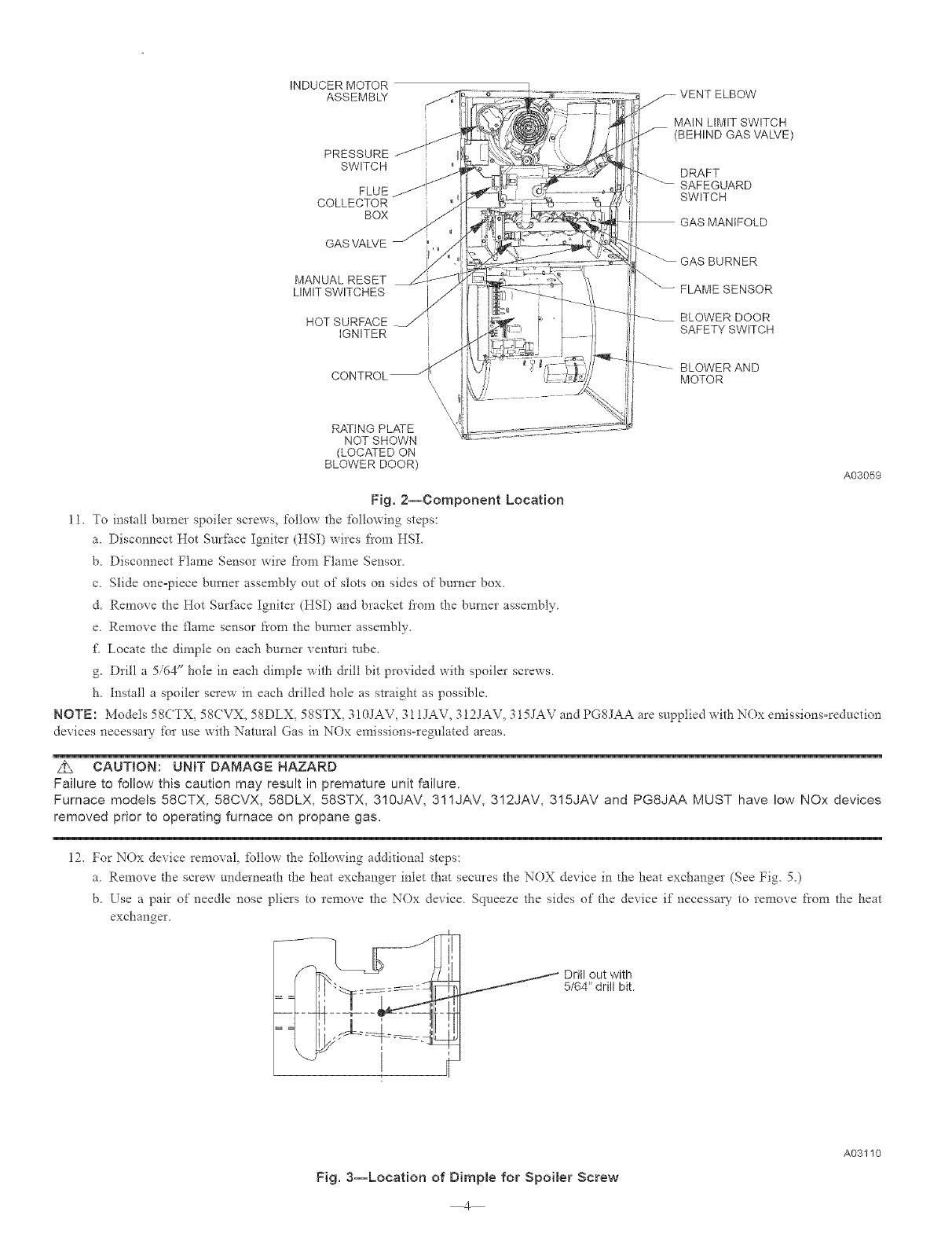
Fig. 2--Component Location
11. To install burner spoiler screw% %llow the %llowing steps:
a Disconnect Hot Surface Igniter (HSI) wires from HSI.
b. Disconnect Flame Sensor wire fi'om Flame Sensor.
c. Slide oneopiece burner assembly out of slots on sides of burner box.
d. Remove the Hot Sur[_ce Igniter (HSI) and bracket flora the burner assembly.
e. Remove the flame sensor from the burner assembly.
£ Locate the dimple on each burner venttlri robe.
g. Drill a 5/64" hole in each dimple with &ill bit provided with spoiler screws.
h. Install a spoiler screw in each &illed hole as straight as possible.
NOTE: Models 58CTX, 58CVX, 58DLX, 58STX, 310JAV, 311JAV, 312JAV, 315JAV and PGSJAA are supplied with NOx emissionsoreduction
devices necessm 7 for use with Natural Gas in NOx emissions=regulated areas.
Z_ CAUTION: UNiT DAMAGE HAZARD
Failure to follow this caution may result in premature unit failure.
Furnace models 58CTX, 58CVX, 58DLX, 58STX, 310JAV, 311JAV, 312JAV, 315JAV and PG8JAA MUST have low NOx devices
removed prior to operating furnace on propane gas.
12. For NOx device removal, %llow the %llowing additional steps:
a Remove the screw underneath the heat exchanger inlet that secures the NOX device in the heat exchanger (See Fig 5.)
b. Use a pair of needle nose pliers to remove the NOx device Squeeze the sides of the device if necessary to remove from the heat
exchanger
_ Drill out with
5/64" drill bit.
Fig, 3--Location of Dimple for Spoiler Screw
4
A03110
BURNER
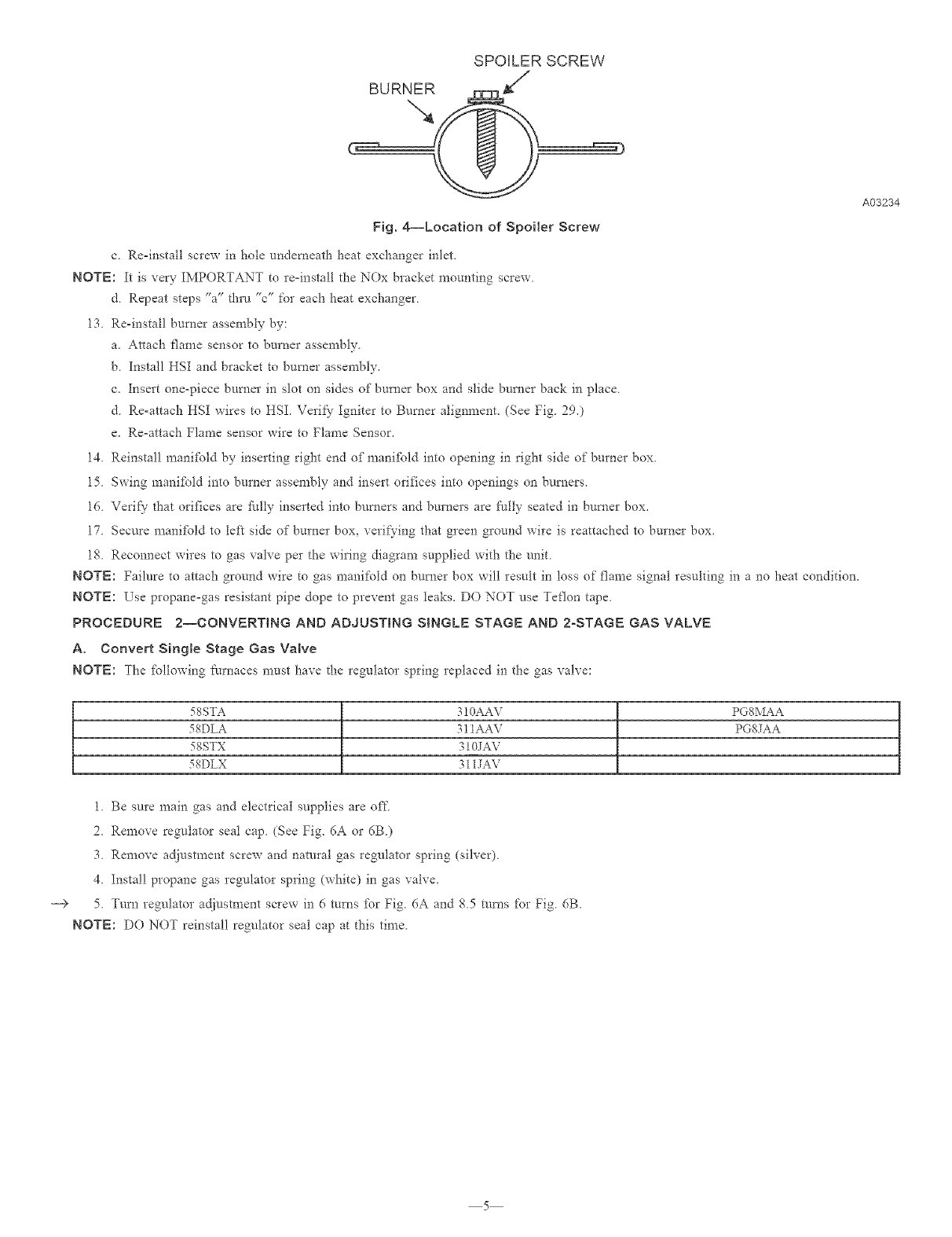
SPOILER SCREW
Fig. 4--Location of Spoiler Screw
c. Re=install screw in hole underneath heat exchanger inlet
NOTE: It is very IMPORTANT to re=install the NOx bracket mounting screw
d Repeat steps %" thrn "c" for each heat exchanger
13 Re-install burner assembly by:
a. Attach flame sensor to burner assembly.
b. Install HSI and bracket to burner assembly.
c. Insert one-piece burner in slot on sides of burner box and slide burner back in place.
d. Re-attach HSI wires to HSI. Verify Igniter to Burner alignment. (See Fig. 290
e. Re=attach Flame sensor wire to Flame Sensor.
14. Reinstall manifbld by inserting right end of manifbld into opening in right side of burner box.
15. Swing manifbld into burner assembly and insert orifices into openings on burners.
16. Verif}- that orifices are Nlly inserted into burners and burners are Nlly seated in burner box.
17. Secure manifbld to left side of burner box, verifying that green ground wire is reattached to burner box.
18. Reconnect wires to gas valve per the wiring diagram supplied with the unit.
NOTE: Failure to attach ground wire to gas manifold on burner box wilt result in loss of flame signal resulting in a no heat condition.
NOTE: Use propane=gas resistant pipe dope to prevent gas leaks. DO NOT use Teflon tape.
PROCEDURE 2--CONVERTING AND ADJUSTING SINGLE STAGE AND 2-STAGE GAS VALVE
A, Convert Single Stage Gas Valve
NOTE: 7he ibllowing Ihrnaces must have the regulator spring replaced in the gas valve:
58STA 310AAV PG8MAA
58DLA 311AAV PG8JAA
58STX 310JAV
58DLX 311JAV
1 Be sure main gas and electrical supplies are off
2Remove regulator seal cap (See Fig. 6A or 6B)
3 Remove adjustment screw and natural gas regulator spring (sih'er)
4 Install propane gas regulator spring (white) in gas valve.
5 Turn regulator adjustment screw in 6 turns for Fig. 6A and 85 rams for Fig 6B.
NOTE: DO NOT reinstall regulator seal cap at this time
A03234
5
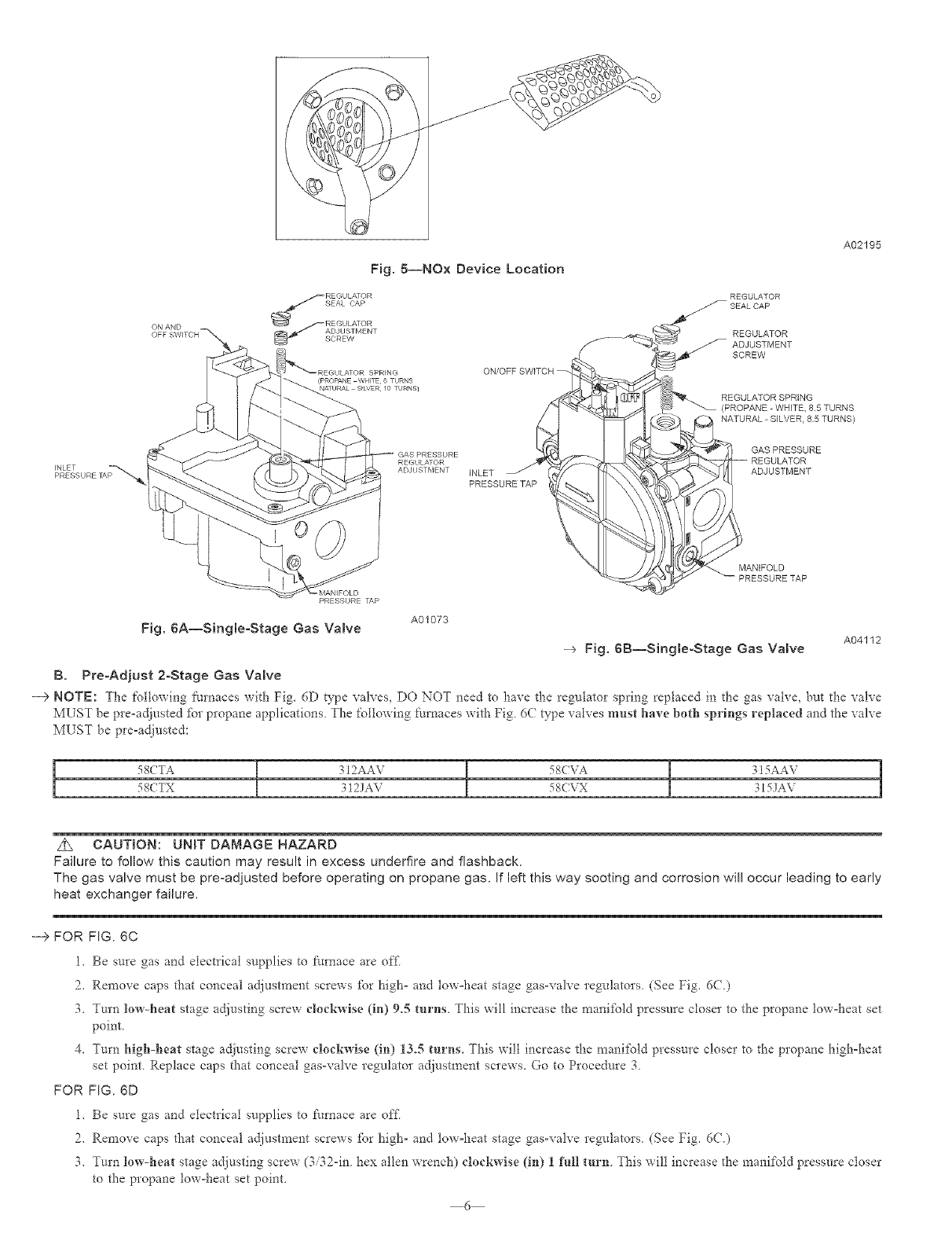
Fig.5--NOxDeviceLocation
(PROPANE WHITE, 6 TURNS
NAqURAL SILVER /0 TURNS}
INLET
PRESSURE TAP
A02195
REGULATOR
_SEALCAP
REGULATOR
ADJUSTMENT
SCREW
REGULATOR SPRING
(PROPANE WHETE, 85 TURNS
NATURAL - SILVER, 85 TURNS)
GAS PRESSURE
ADJUSTMENT
MANIFOLD
PRESSURE TAP
Fig. 6A--Sing[eoStage Gas Valve A01073
--> Fig, 6B--Sing[eoStage Gas Valve A04112
B. PreoAdjust 2oStage Gas Valve
---> NOTE: The %llowing [_urnaces with Fig. 6D type valves, DO NOT need to have the regulator spring replaced in the gas valve, but the valve
MUST be pre-adjusted _br propane applications The following furnaces with Fig 6(} type valves must have both springs replaced and the valve
M_ST be pre-adjusted:
!
!
Z_ CAUTION: UNBT DAMAGE HAZARD
Failure to follow this caution may result in excess underfire and flashback.
The gas valve must be pre-adjusted before operating on propane gas. If left this way sooting and corrosion will occur leading to early
heat exchanger failure,
--> FOR FIG. 6C
1. Be sure gas and electrical supplies to furnace are off
2. Remove caps that conceal adjustment screws for high- and tow-heat stage gas-valve regulators (See Fig. 6C)
3. Tm'n low-heat stage adjusting screw clockwise (in) 9.5 turns. This will increase the mani_bld pressure closer to the propane low-heat set
point.
4. Turn Mgh-heat stage adjusting screw clockwise (in) 13.5 turns. This will increase the mani[bld pressure closer to the propane high-heat
set point. Replace caps that conceal gas-valve regulator adjusm_ent screws. Go to Procedure 3.
FOR FIG. 6D
1. Be sure gas and electrical supplies to _:urnace are of_:
2. Remove caps that conceal adjustment screws for high- and tow-heat stage gas-valve regulators. (See Fig. d(L)
3. Turn low-heat stage adL}usting screw (3/32-in. hex allen wrench) clockwise (in) 1 Nil turn. This will increase the manifold pressure closer
to the propane low-heat set point.
6
ON/OFF SWITCH
INLET
PRESSURE TAP
f_]_ _ PLASTIC ADJUST SCREW
HIGH STAGE GAS
PRESSURE REGULATOR
(PROPANE-WHITE, 135 TURNS
NATURAL-SILVER 12 TURNS)
GAS PRESSURE
REGULATORADJUSTMENT
(PROPANE-WHITE 95 TURNS
NATURA_SILVER,95 TURNS)
MANIFOLD
PRESSURE TAP
A04048
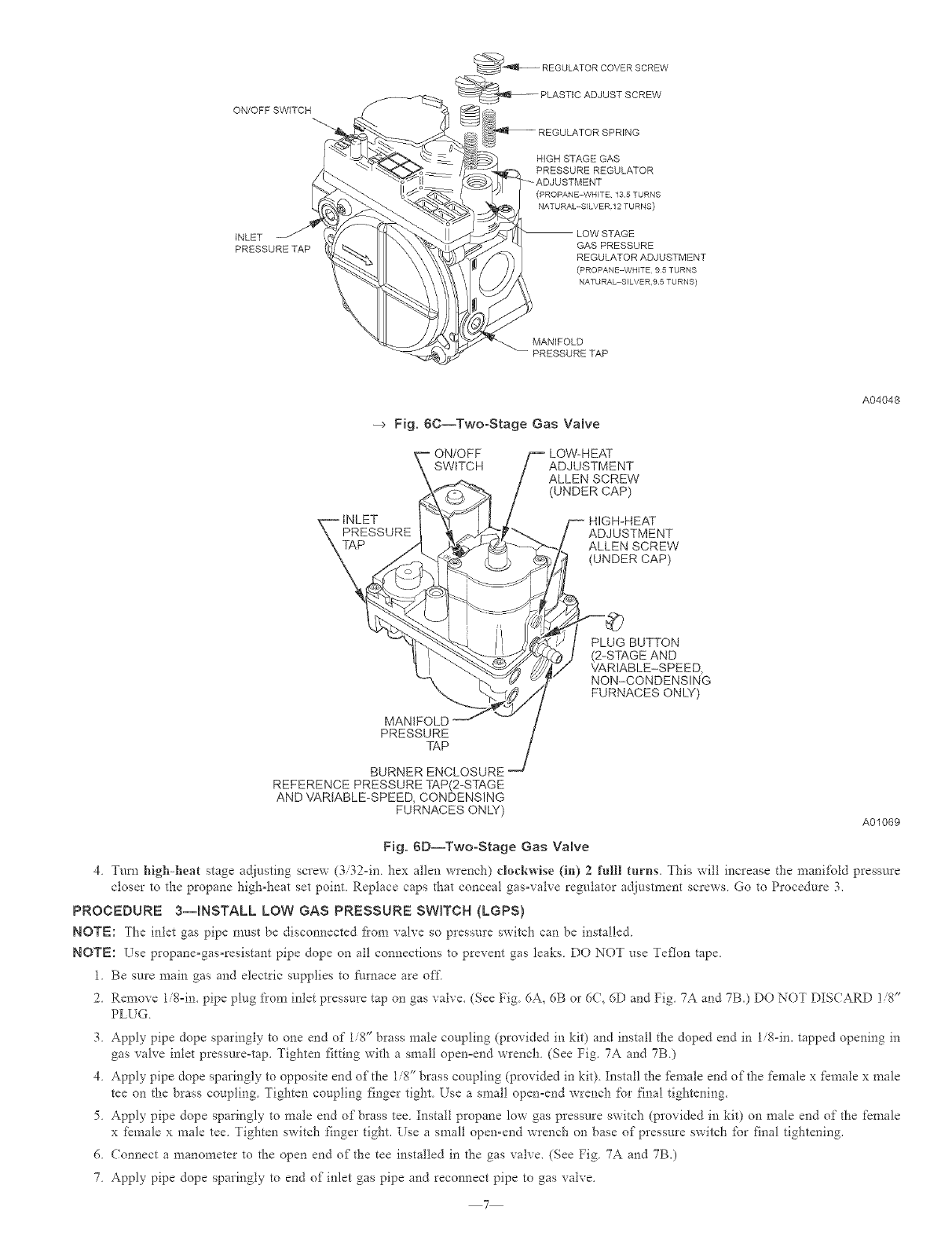
--> Fig, 8C--TwooStage Gas Valve
ON/OFF
SWITCH ADJUSTMENT
ALLEN SCREW
(UNDER CAP)
_pE tNLET
SSURE
MANIFOLD t
PRESSURE /
TAP /
BURNER ENCLOSURE
REFERENCE PRESSURE TAP(2-STAGE
AND VARIABLE-SPEED, CONDENSING
FURNACES ONLY)
HIGH-HEAT
ADJUSTMENT
ALLEN SCREW
(UNDER CAP)
VARIABLE-SPEED,
NON-CONDENSING
FURNACES ONLY)
A01069
Fig. 8D--TwooStage Gas Valve
4 Turn high-heat stage adfllsting screw (3/32-in hex allen wrench) clockwise (in) 2 fulll turns. This will increase the mani%ld pressure
closer to the propane high-heat set point. Replace caps that conceal gas-valve regulator adjustment screws Go to Procedure 3.
PROCEDURE 3--INSTALL LOW GAS PRESSURE SWITCH {LGPS)
NOTE: The inlet gas pipe must be disconnected fi'om valve so pressure switch can be installed
NOTE: Use propane-gas-resistant pipe dope on all connections to prevent gas leaks. DO NOT use Teflon tape.
1. Be sure main gas and electric supplies to fllmace are oft
2. Remove 1i%im pipe plug fi'om inlet pressure tap on gas valve. (See Fig. 6A_ 6B or 6C, 6D and Fig. ?A and ?B.) DO NOT DISCARD i/8"
PLUG.
3. Apply pipe dope sparingly to one end of 1/8" brass male coupling (provided in kit) and install the doped end in 1/8-in. tapped opening in
gas valve inlet pressure-tap. Tighten fitting with a small open-end wrench. (See Fig. 7A and 7B.)
4. Apply pipe dope sparingly to opposite end of the 1/8" brass coupling (provided in kit). Install the fkmale end of the fen?ale x female x male
tee on the brass coupling. Tighten coupling finger tight. Use a small open-end wrench for final tightening.
5. Apply pipe dope sparingly to male end of brass tee. Install propane low gas pressure switch (provided in kit) on male end of the female
x fen?ale x male tee. Tighten switch finger tight. Use a small open-end wrench on base of pressure switch for final tightening.
6. Connect a manometer to the open end of the tee installed in the gas valve. (See Fig. 7A and 7B.)
7. Apply pipe dope sparingly to end of inlet gas pipe and reconnect pipe to gas valve.
7
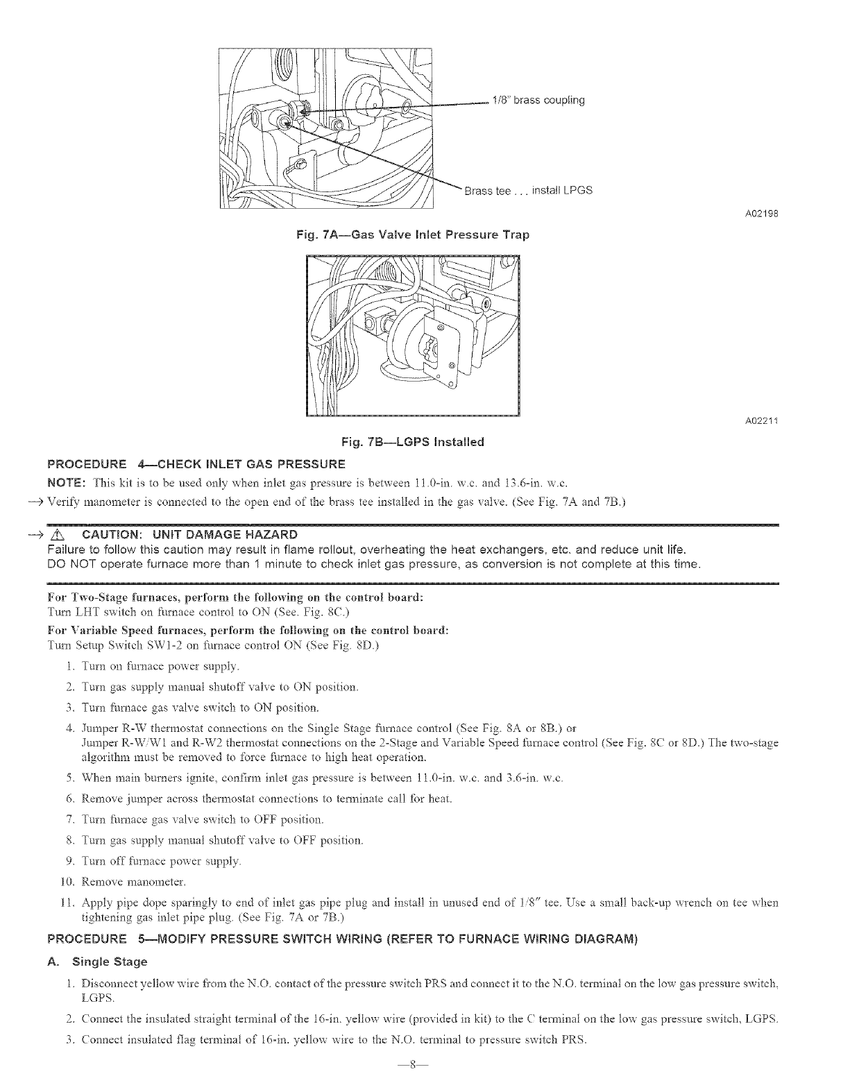
1/8" brass coupling
"_ Brass tee.., install LPGS
Fig. 7A--Gas Valve inlet Pressure Trap
A02198
A02211
Fig. 7B--LGPS Installed
PROCEDURE 4--CHECK iNLET GAS PRESSURE
NOTE: This kit is to be used only when inlet gas pressure is between II 0=in we. and 13.6=in. we.
--->Verify manometer is connected to the open end of the brass tee installed in the gas valve. (See Fig. 7A and 7B.)
--> z_ CAUTION: UNiT DAMAGE HAZARD
Failure to follow this caution may result in flame rol!out, overheating the heat exchangers, etc, and reduce unit life.
DO NOT operate furnace more than 1 minute to check inlet gas pressure, as conversion is not complete at this time,
For Two-Stage furnaces, perform the following on the control board:
Turn LHT switch on _:arnace control to ON (See. Fig. 8()
For Variable Speed furnaces, perform the following on the control board:
Tm_l Setup Switch SWI-2 on £hmace control ON (See Fig 8D.)
1. Turn on _:urnace power supply
2. Turn gas supply manual shutoff valve to ON position
3. Turn furnace gas valve switch to ON position
4. Jumpe* R-W thermostat connections on the Single Stage furnace control (See Fig 8A or 8B.) or
Jumper R-W/W1 and R-W2 thermostat connections on the 2-Stage and Variable Speed furnace contlol (See Fig. 8(7 or 8D.) The two=stage
algorithm must be removed to force _;amace to high heat operation.
5. When main burners ignite, confirm inlet gas pressure is between 11.0=in. we. and 36=in w.c
6. Remove jumper across thermostat connections to tem_inate call for heat.
7. Turn _hmace gas valve switch to OFF position.
8. Turn gas supply manual shutoff valve to OFF position.
9. Turn off furnace power supply.
10. Remove manometer.
11. Apply pipe dope sparingly to end of inlet gas pipe plug and install in unused end of 1/8" tee Use a small back-up wrench on tee when
tightening gas inlet pipe plug (See Fig. 7A or 7B)
PROCEDURE g--MODIFY PRESSURE SWITCH WIRING (REFER TO FURNACE WIRING DIAGRAM)
A. Singme Stage
1. Disconnect yellow wire fi'om the N.O. contact of the pressure switch PRS and connect it to the N.O. tem_iual on the low gas pressure switch,
LGPS
2. (onnect the insulated straight tem_inal of the 16-in yellow wire (provided in kit) to the ( tem_inai on the low gas pressure switch, LGPS
3. (onnect insulated f]ag terminal of 16-in. yellow wire to the N.O. terminal to pressure switch PRS.
8
4.Routeyellowwiresalongwireharness.Securewithwiretieprovidedinkit.GotoProcedure6.
B. 2-Stage and Variable Speed
1. Disconnect yellow wire from the N.O. contact of the tow-heat pressure switch LPS and connect it to the N.O. terminal on the low gas
pressure switch, LGPS.
2. Connect insulated stlaight terminal of 16=in. yellow wire (provided in kit) to ( terminal on low gas pressure switch LGPS.
3. Connect insulated flag terminal of 16=in. yellow wire to N.O. terminal to low pressure switch LPS.
4. Route yellow wires along wire harness. Secure with wire tie provided in kit. Go to Procedure 6.
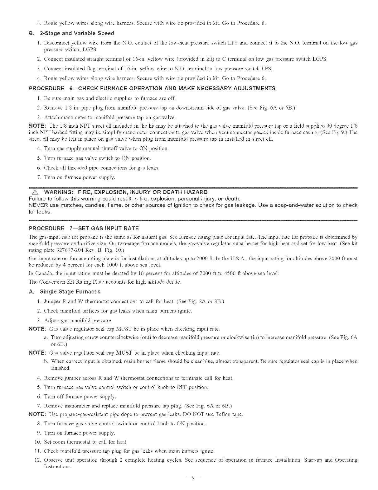
PROCEDURE g--CHECK FURNACE OPERATmON AND MAKE NECESSARY ADJUSTMENTS
1 Be sure main gas and electric supplies to furnace are off
2 Remove 1/8=in. pipe plug t'rom manii;old pressure tap on downstream side of gas valve (See Fig. 6A or 6B)
3 Attach manometer to manifold pressure tap on gas valve
NOTE: The 1/8 inch NPT stleet ell included in the kit may be attached to the gas valve manifold pressure tap or a field supplied 90 degree 1/8
inch NPT barbed fitting may be simplify7 manometer connection to gas valve when vent connector passes inside furnace casing (See Fig 9.) The
street ell may be left in place on gas vah'e when plug fiom manifold pressure tap in installed in street ell.
4. Turn gas supply manual shutoff valve to ON position.
5. Turn I:urnace gas valve switch to ON position.
6. Check all threaded pipe connections for gas leaks.
7 Turn on furnace power supply,
Z_ WARNING: HRE, EXPLOSION, INJURY OR DEATH HAZARD
Failure to follow this warning could result in fire, explosion, personal injury, or death.
NEVER use matches, candles, flame, or other sources of ignition to check for gas leakage, Use a soap-and-water solution to check
for leaks.
PROCEDURE 7--SET GAS INPUT RATE
7he gas=input rate for propane is the same as for natural gas. See furnace rating plate fbr input rate. The input rate fbI propane is determined by
manifbld pressure and orifice size. On two=stage I:umace models, the gas=valve regulator must be set for high heat and set fbr low heat. (See kit
rating plate 327697°204 Rev. B, Fig. 10.)
Gas input rate on furnace rating plate is fbr installations at ahimdes up to 2000 ft. In the U.S.A., the input rating for ahitudes above 2000 ft nmst
be reduced by 4 percent for each 1000 t't above sea level.
In (anada, d_e input rating must be derated by 10 percent fbr altitudes of 2000 ft to 4500 ff above sea level.
The Conversion Kit Rating Plate accounts fbr high altitude derate.
A. Single Stage Furnaces
1 Jumper R and W thermostat connections to call for heat (See Fig. 8A or 8B)
2. Check manil\fld orifices for gas leaks when main burners ignite.
3. Adjust gas manifold pressure.
NOTE: Gas valve regulator seal cap MUST be in place when checking input rate.
a. Turn adjusting screw counterclockwise (out) to decrease manifbld pressure or clockwise (in) to increase manifold pressure. (See Fig. 6A
or 6B.)
NOTE: Gas valve regulator seal cap MUST be in place when checking input rate.
b. When correct input is obtained, main burner flame should be clear blue, almost transparent. Be sure regulator seal cap is in place when
finished.
4. Remove jumper across R and W thermostat connections to terminate call for heat.
5. Turn Nrnace gas valve control switch or control knob to OFF position.
6. Turn off Nmace power supply.
7. Remove manometer and replace manii;old pressure tap plug. (See Fig. 6A or dB.)
NOTE: Use propane=gas=resistant pipe dope to prevent gas leaks. DO NOT use Teflon tape.
8. Turn Nrnace gas valve control switch or control knob to ON position.
9. Turn on Nrnace power supply.
10. Set room them?ostat to call for heat.
11. Check manifbld pressure tap plug fbr gas leaks when main burners ignite.
12. Observe unit operation through 2complete heating cycles. See sequence of operation in Nrnace Installation, Start-up and Operating
Instructions.
9
24 VTHERNOS rA-
TERMINALS
3 AMPFUSE ---
LEDOPERATION & _
D_AGNOSTICr IGHT
I _5 VAC_L2)NEUTRAL......
CONNECTIONS
8LOWER SPEED _ _
SELECTION TERN_NALS
TWINNINGAND,OR
BLOWER OFF 9ELAY CONPONENTTEST
\ TERMINAL
J2 JUMPER •
FiE]
c PL2 HOT SURFACE
, = _ := _GNITER&INDUOER
L VOL-AC_E CONNB TION MOTOR CONNECTOR
HUMIDIFIERTERMINAL
_24VAC0 _,AMPMA,X
TRANSFOR_,_ER24 VAC
CONNECTIONS
PL_LOWVOLTAGEMAIN
HARNESSCONNECTOR
SET JR SWITCHES
LOW HEA _ ONLY AND
BLOWER OFF DELAY
F
24 V THERMOSTA J
TERMNALS
HUMIDIFIER TERMINAL
(24 VAC D 5 AMP blAX )
3 AMP FUSF_
LED OPERATION &/
DIAGNOST]C IGHT
/ 5 VAC 2) NEUTRAL _
CONNECT ONS
TWiN NING AND/OR
COMPONENT TEST
TERMINAL
T'N" TRANSFORMER24VAC
<,O,,ECTONS
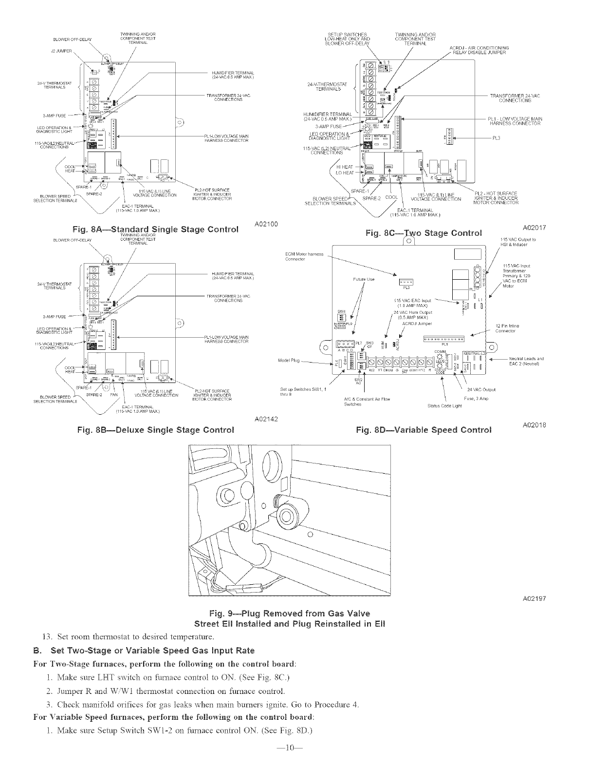
Fig. 8A--Standa[d.oSing_e Stage Control
BLOWER OFF DELAY COMPONENTTEST
TERMINAL
\\ ,\
/
N
...............-!,5TERMINALS 5\
3 AMP _USE -- 4
D_AGNOSTICr IGHT 1
I _5 VAC(L2)NEUTRAL......
O©NNEOTIONS
A02100
HUMIDIFIER TERMINAL
_24VAC 0 _,AMPMAX
TRANSFORMER24 '_C
CONNECTIONS
PL_LOWVOLTAGEMAIN
HARNESSCONNECTOR
ECM MOtOl harness
Connector
A02017
Fig. 8C--_o_O Stage Control ,svACOu_,,u,o
HSI & _nducer
Fig. 8B--Deluxe Single Stage Control
A02142
A,O & Constal/t Air Flow Fuse 3 Am_)
Sw tches Stat }s Code Light
Fig. 8D--Variable Speed Control A02018
Fig. 9--Plug Removed from Gas Valve
Street Eli Installed and Plug Reinstalled in Ell
13. Set roopa them_ostat to desi_'ed ten_pe_'atore.
B. Set Two-Stage or Variable Speed Gas Input Rate
For Two-Stage furnaces, perform the followiag oa the coatrol board:
1. Make sure LXT switch on fbmace control to ON (See Fig. gC.)
2. Jumpe* Rand WiWI thermostat coanectioa on £umac6 control.
3. Check manifold orifices for gas teaks when main bume*s ignite. Go to Procedure 4
For Variable Speed furnaces, perform the following on the control board:
1. Make sure Setup Switch SW1-2 on 5_rnace control ON (See Fig. SD.)
I0
A02197
f
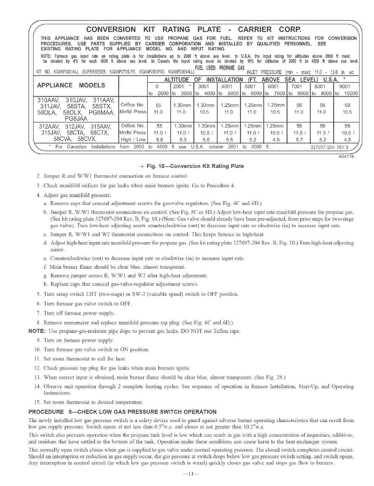
/CONVERSION KIT RATING - CARRmER CORR ""
THiS APPLIANCE HAS SEEN CONVERTED TO USE PROPANE GAS FOR FUEL, REFER TO KiT iNSTRUCTiONS FOR CONVERSiOn
PROCEDURES, USE PARTS SUPPLIED BY CARRIER CORPORATION AND iNSTALLED BY QUALiFiED PERSONNEL, SEE
EXiSTiNG RATING PLATE FOR APPLIANCE MODEL NO, AND iNPUT RATING,
NOTE:Furnace gas input rate on rating plate is for insNIations up to 2000 fit above sea teve[ in U,S,A, the input rating for altitudes above 2000 ft must
be derated by 4% for each 1000ft above sea Ieve[ in Canadathe input rating must be derated by 10% for altitudes of 2000 ft to 4500 ft above sea level
FUELUSED:PROPANEGAS
<IT NO KGANP3001ALL(SUPERSEDES:KGANP2701LPSKGANP2801F80KGANP2901ALL) INLET PRESSURE(man - max): II.0 - I3.6 in. wc
ALTITUDE OF iNSTALLATiON {FT. ABOVE SEA LEVEL) U.S.A. *
APPLIANCE MODELS 0 2001 3001 4001 5001 6001 7001 8001 9001
to 2000 to 3000 to 4000 to 5000 to 6000 to 7000 to 8000 to 9000 to 10000
310AAV, 310JAV, 311AAV,
311JAV, 58STA, 58STX,
58DLA, 58DLX, PG8MAA,
PG8JAA
312AAV, 312JAV, 315AAV,
315JAV, 58CTA, 58CTX,
58CVA, 58CVX,
Orifice No. 55 1.30mm 1.30mm 1.25mm 1.25mm 1.25mm 56 56 56
Mnfld Press 11.0 11.0 10.5 11.0 11.0 10.5 11.0 11.0 10.5
Orifice No. 55 1.30mm 1.30mm 1.25mm 1.25mm 1.25mm 56 56 56
Mnfld Press 11.0 /11.0 /10.5 /11.0 /11.0 /10.5 /11 .O /11.0 /10.5 /
High /Low 5.8 5.3 5.0 5.5 5.2 4.9 5.7 5.2 4.8
A04118
--> Fig, 10--Conversion Kit Rating Plate
2 Jumper R and W/W1 daem_ostat connection on f:urnace control
3 Check manifbld orifices for gas leaks when main burners ignite Go to Procedure 4
4. Adjust gas manifold pressure.
a. Remove caps that conceal ac{iustment screws fPr gas=valve regulators. (See Fig. 6C and 6D.)
b. Junaper R, W/W1 themaostat connections on control. (See Fig. 8C or 8D.) Adjust tow-heat input rate manifold pressure tbr propane gas.
(See kit rating plate 327697-204 Rev. B, Fig. 10.) (Note: Gas valve should alrea@ have been pre-adjuste& from prior steps for two-stage
gas valve). Turn tow=heat adjusting screw counterclockwise (out) to decrease input rate or clockwise (in) to increase input rate.
c. Jumper R. W/W1 and W2 thermostat connections on control. This keeps fhmace in high-heat.
d. Adjust high-heat input rate manifold pressure _br propane gas. (See kit rating plate 327697-204 Rev. B, Fig. 10.) Turn high=heat adjusting
screw.
e. Counterclockwise (ou0 to decrease input rate or clockwise (in) to increase input rate.
f Main burner flanae should be clear blue, almost transparent.
g. Renaove junaper across R, W/W1 and W2 after high-heat adjustment.
h. Replace caps that conceal gas=valve=regulator adjustment screws.
5. Turn setup switch LHT (two=stage) or SW-2 (variable speed) switch to OFF position.
6. Turn I_umace gas valve switch to OFF.
7. Turn off Nmace power supply.
8. Remove manometer and replace manifold pressure tap plug. (See Fig. 6( and 6D0
NOTE: Use propane-gas-resistant pipe dope to prevent gas leaks. DO NOT use Teflon tape.
9. Turn on Nmace power supply.
10. Turn Nrnace gas valve switch to ON position.
11. Set room tlaem?ostat to call _br heat.
12. Check pressure tap plug fPr gas leaks when main burners ignite.
13. When correct input is obtained, main burner ftanae should be clear blue, alnaost transparent. (See Fig. 28.)
14. Observe unit operation through 2 complete heating cycles. See sequence of operation in Nmace Installation, Start-Up, and Operating
Insm/ctions.
15 Set room thermostat to desired temperature
PROCEDURE 8--CHECK LOW GAS PRESSURE SWITCH OPERATION
_he newly installed tow gas pressure switch is a safety device used to guard against adverse burner operating characteristics that can resuh flora
low gas supply pressure, Switch opens at not tess than 6,5"w c and closes at not greater than 10,2%v c,
This switch also prevents operation when the propane tank level is low which can resuh in gas with a high concenuation of impurities, additives,
and residues that have settled to the bottona of the tank. Operation under these conditions can cause harna to the heat exchanger system.
This normally open switch closes when gas is supplied to gas valve under nomaai operating pressure. The closed switch conapletes control circuit.
Should an intemlptien or reduction in gas supply occur, the gas pressure at switch &ops below low gas pressure switch setting, and switch opens.
Any interruption in control circuit (in which tow gas pressure switch is wired) quickly closes gas valve and stops gas flow to burners.
11
Outer
door
m........ B
Blower Door
Factory
Clearance
Label
I Rating Plate on
exterior of door
Existing Warning Label
C_
Apply Conversion
Responsibility Label
on exterior of door
Factory information
Label
-->
--€
A02203
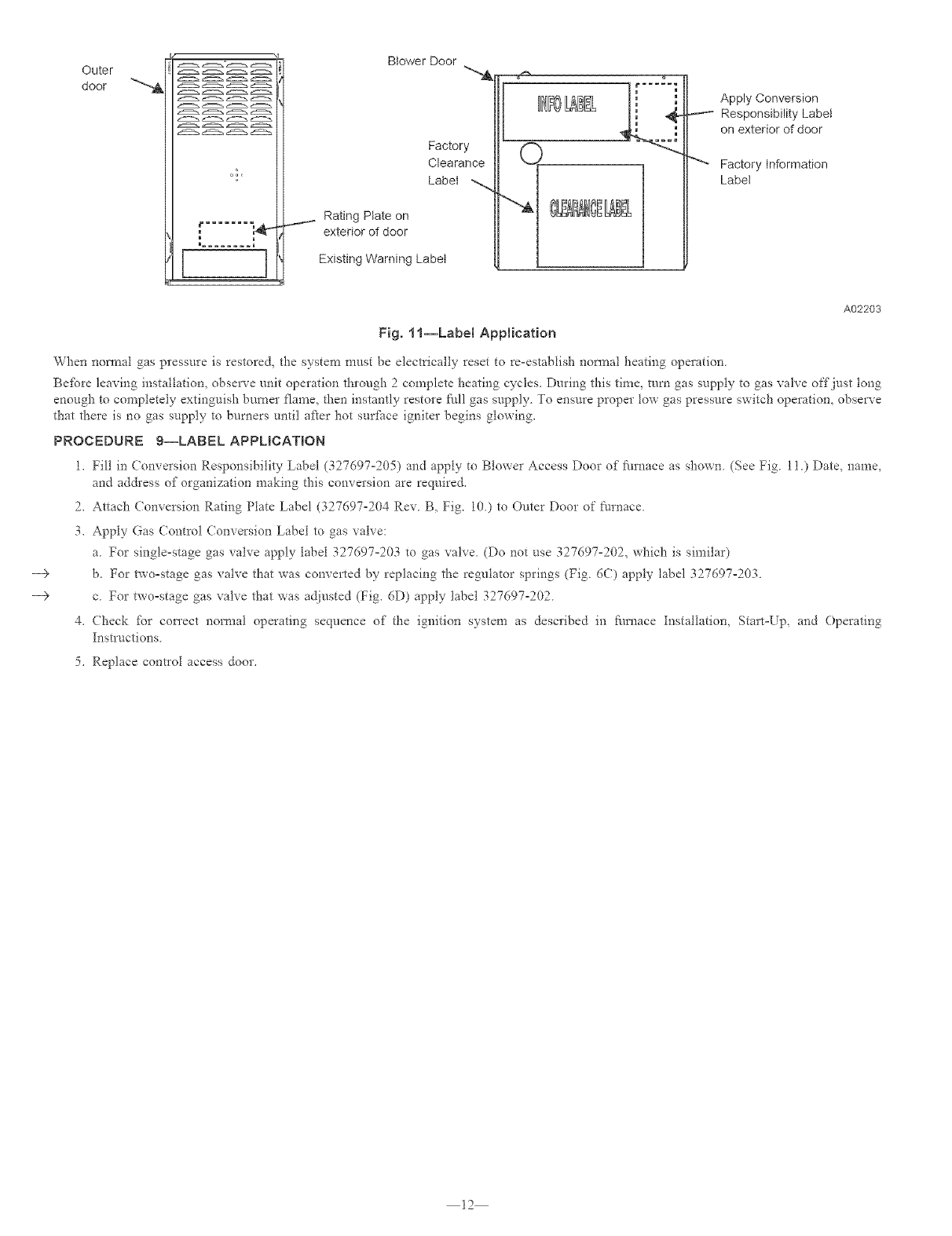
Fig. 1 l--Label Application
When nonnal gas pressure is restored, the system must be electrically reset to re-estahlish nonnal heating operation.
Befbre leaving installation, observe unit operation through 2 complete heating cycles. During this time, turn gas supply to gas valve off just tong
enough to completely extinguish burner flame, then instantly restore f_all gas supply. To ensure proper tow gas pressure switch operation, observe
that there is rio gas supply to burners until after hot surfhce igniter begins glowing.
PROCEDURE g--LABEL APPUCATION
1. Fill in Conveision Responsibility Label (327697=205) and apply to Blowei Access Door of" fire, ace as shown. (See Fig. 1i.) Date, name,
arid ad&ess of organization making this conversion are required.
2. Attach Conversion Rating Plate Label (327697-204 Rev. B, Fig. 10.) to Outer Door of furnace.
3. Apply Gas (ontrol (onversion Label to gas valve:
a. For single=stage gas vah'e apply label 327697°203 to gas valve. (Do riot use 327697°202, which is similar)
b. For two=stage gas valve that was converted by replacing the regulator springs (Fig. 6C) apply label 327697-203.
c. For two=stage gas valve that was adjusted (Fig. 6D) apply label 327697-202.
4. Check fbr correct normal operating sequence of the ignition system as described in fl/rnace Installation, Start-Up, and Operating
Instructions.
5. Replace control access door.
12
mNSTALLATION
SECTION 2- INDUCED-COMBUSTION, HOT-S1JRFACE IGNITION, SINGLE STAGE, T_,¥O-STAGE AND VARIABLE-SPEED,
40-INCH NON-CONDENSING FURNACES MODELS
SINGLE-STAGE MODELS TWO-STAGE MODELS VARIABLE SPEED MODELS
58PAV 383KAV PG8UAA 58TUA 330AAV 58UHV 333BAV
58WAV 395(AV PG8DAA 58TMA 331AAV 58URV 3331AV
58RAV 373LAV 393AAV 58UXT 330JAV
58ZAV 376CAV 58YAV 58DXT 331JAV
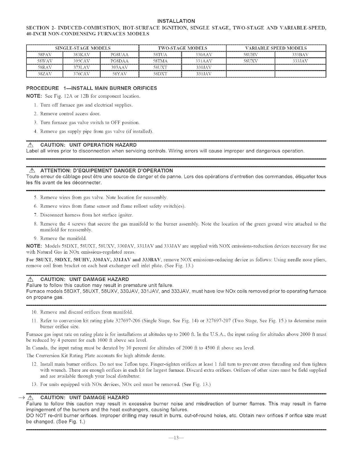
PROCEDURE I--INSTALL MAIN BURNER ORIFICES
NOTE: See Fig 12A or 12B fbr component location
1 Turn off fl/mace gas and electIical supplies,
2. Remove control access door,
3 Turn fm'nace gas valve switch to OFF position.
4 Remove gas supply pipe from gas valve (if installed)
Z_ CAUTmON: UNmT OPERATION HAZARD
Labe! all wires prior to disconnection when servicing controls. Wiring errors will cause improper and dangerous operation,
___ ATTENTION: D'EQUBPEMENT DANGER D'OPERATmON
Toute erreur de c_blage peut 6tre une source de danger et de panne, Lors des operations d'entretien des commandes, etiqueter tous
les ills avant de les deconnecter,
5 Remove wires fi'om gas valve Note location [br reassembly
6 Remove wires fi'om flame sensor and flame rollout safety switch(es).
7. Disconnect harness fiom hot surface igniter.
8. Remove the 4 screws that secure the gas manitbld to the burner assembly. Note the location of the green ground wire attached to the
manifbld for reassembly.
9. Remove the manifold.
NOTE: Models 58DXT, 58UXT, 58UXV, 330JAV, 331JAV and 333JAV are supplied with NOX emissions-reduction devices necessa V _br use
with Natural Gas in NOx emissions-regulated areas.
For 58UXT, 58DXT, 58UHV, 330JAV, 331JA¥ and 333BAV, remove NOX emissions=reducing device as follows: Using needle nose pliers,
remove coil fi'om bracket on each heat exchanger cell inlet plate. (See Fig. 13.)
Z_ CAUTION: UNmT DAMAGE HAZARD
Failure to follow this caution may result in premature unit failure,
Furnace models 58DXT, 58UXT, 58UXV, 33g JAY, 331JAV, and 333JAY, must have low NOx coils removed prior to operating furnace
on propane gas,
10 Remove and discard orifices from mani_bld
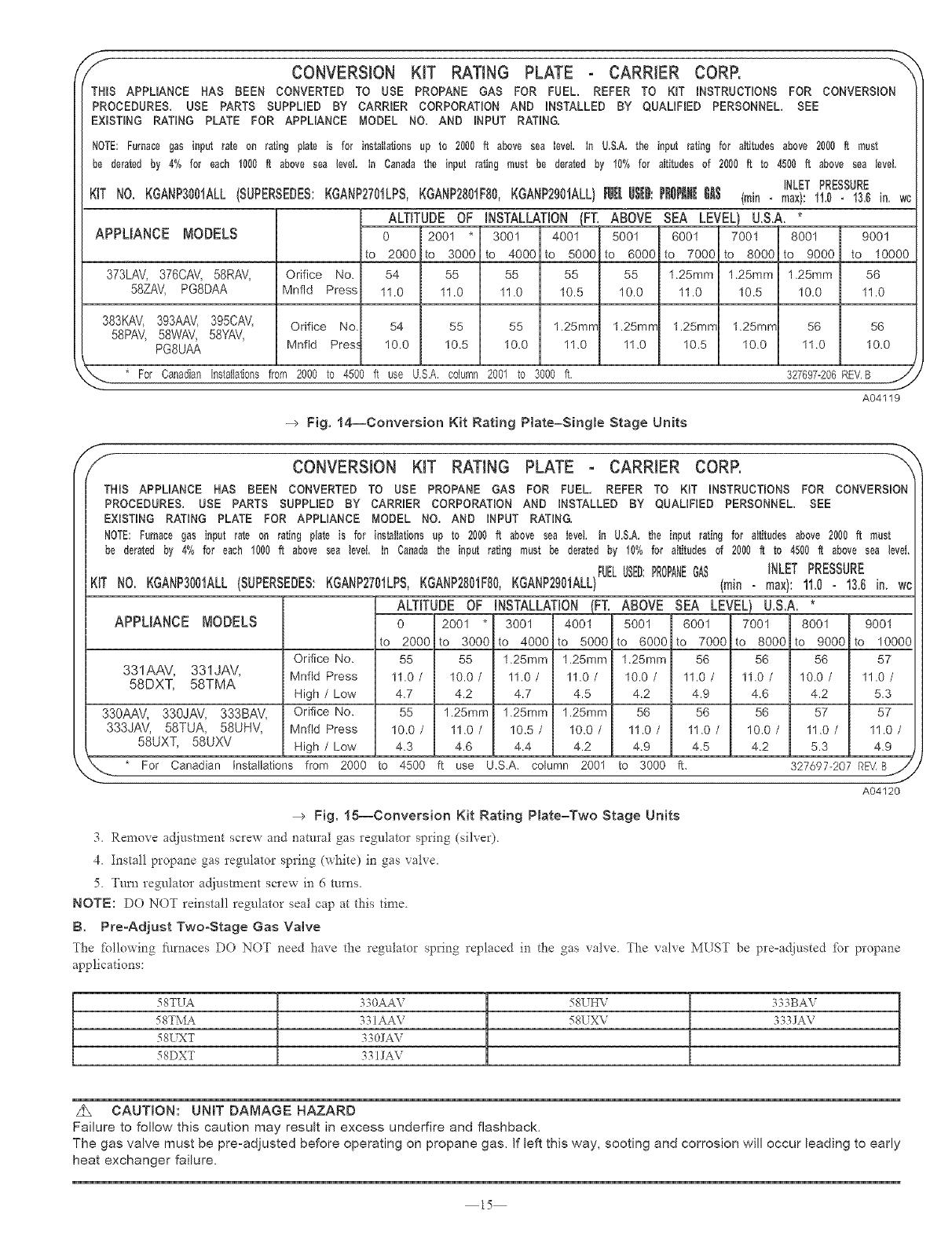
11 Refkr to conversion kit rating plate 327697°206 (Single Stage, See Fig 14) or 327697-207 (Two Stage, See Fig. 15) to detem_ine main
burner orifice size.
Furnace gas input rate on rating plate is for installations at altitudes up to 2000 ft. In the U.S.A., the input rating for altitudes above 2000 ft must
be redt/ced by 4 percent for each 1000 ft above sea level.
In Canada, the input rating must be derated by 10 percent _br altitudes of 2000 _t to 4500 k above sea level.
The Conversion Kit Rating Plate accounts for high altitude derate.
12. Install main burner orifices. Do not use Teflon tape. Finger-tighten orifices at least 1 full mm to prevent cross threading and then tighten
with wrench. There are enough orifices in each kit _br largest _i/mace. Discard extra orifices. Orifices of other sizes must be field supplied
and are available through your local distributor.
13. For units equipped with NOx devices, NOx coil must be removed. (See Fig. 130
--> z_ CAUTmON: UNiT DAMAGE HAZARD
Failure to follow this caution may result in excessive burner noise and misdirection of burner flames, This may result in flame
impingement of the burners and the heat exchangers, causing failures.
DO NOT re-dril! burner orifices, improper drilling may result in burrs, out-of-round holes, etc, Obtain new orifices if orifice size must
be changed. (See Fig, 1.)
13
_/------BLOWER
COMPARTMENT
DOOR
CONV R ',O --X,
PLATE _ I_/Y_-'_ I
GAS VALVE _ L! Jl_'_l
CONVERSION --'
RESPONSIBILITY
LABEL
GAS CONTROL
CONVERSION
LABEL
BURNER
HOLD-DOWN
BRACKET
-- MANIFOLD
A95459
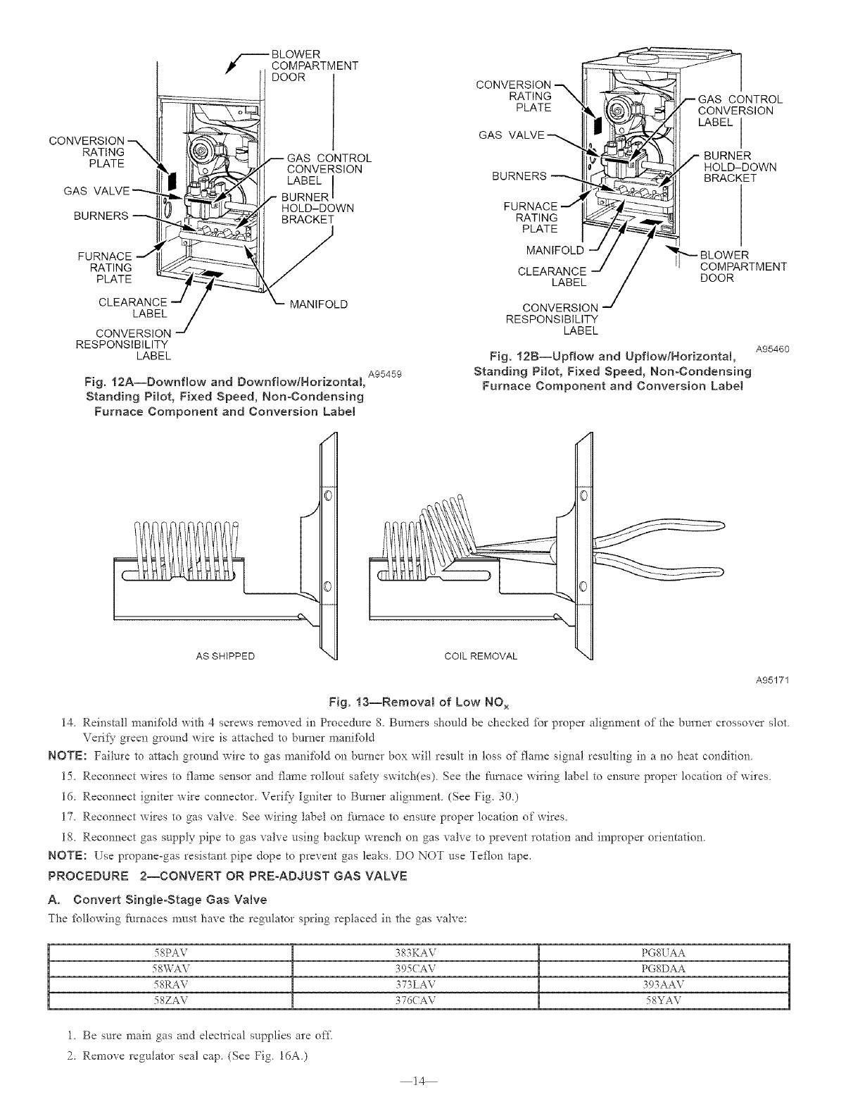
Fig. 12A--Downflow and Downfiow/Horizontal,
Standing Pilot, Fixed Speed, NonoCondensing
Furnace Component and Conversion LabeJ
CONVERSION -x
RATINGX t _ _7--_IL---GAS CONTROL
PLATE ___(_' :_j_ €O_N_VERSlON
lY- a-ilV HOLD-DOWN
BURNERS _ I_ _I BRACKET
FURNACE I_- _lJ I
RATING _:_:_ _II I
PLATE 7_ _ I
MANIFOLD .d /_' BLOWE'R
CLEARANCE __/// /_"_"-- CO M PARTM ENT
LABEL /DOOR
CONVERSION --'
RESPONSIBILITY
LABEL
Fig. 12B--Upflow and Upflow/HorizontN,
Standing Pilot, Fixed Speed, Non-Condensing
Furnace Component and Conversion LabeJ
A95460
AS SHIPPED COIL REMOVAL
A95171
Fig. 13--Removal of Low NO x
14, Reinstall manifold with 4screws removed in Procedure 8, Burners should be checked _br proper alignment of the burner crossover slot
Verify green ground wire is attached to burner mani_bld
NOTE: Failure to attach ground wire to gas manifold on burner box will result in toss of flame signal resulting in a no heat condition.
15, Reconnect wires to flame sensor and flame rollout sa_kty switch(es), See the _lmace wiring label to ensure proper location of wires.
16. Reconnect igniter wire connector. Verif}" Igniter to Burner alignment. (See Fig. 30,)
17, Reconnect wires to gas valve. See wiring label on £_/mace to ensure proper location of wires.
18, Reconnect gas supply pipe to gas valve using backup wrench on gas valve to prevent rotation and improper orientation.
NOTE: Use propane-gas resistant pipe dope to prevent gas leaks. DO NOT use Teflon tape.
PROCEDURE 2--CONVERT OR PREoADJUST GAS VALVE
A, Convert SingleoStage Gas Valve
_he _bllowing furnaces must have the regulator spring replaced in the gas valve:
58PAV 383KAV PGS'UAA
58WAV 395(AV PGSDAA
58I,L&V 373 LAV 393AAV
58ZAV 376(AV 58¥AV
1, Be sure main gas and electrical supplies are of£
2, Remove regulator seal cap, (See Fig. 16A,)
14
_'_ CONVERSION KIT RATING PLATE - CARRIER CORR
THiS APPLIANCE HAS SEEN CONVERTED TO USE PROPANE GAS FOR FUEL. REFER TO KiT iNSTRUCTiONS FOR CONVERSION
PROCEDURES. USE PARTS SUPPLIED BY CARRIER CORPORATION AND iNSTALLED BY QUALiFiED PERSONNEL. SEE
EXiSTiNG RATING PLATE FOR APPLIANCE MODEL NO, AND iNPUT RATING.
NOTE:Furnacegas input rate on rating plate is for instaiIationsup to 2000 ft above sea IeveL in U,S,A,the input rating for altitudes above 2000 ft must
be derated by 4% for each 1000 ft above sea level, in Canadathe input rating must be derated by 10% for affitudesof 2000 ff to 4500 ft above sea ieveL
Kff NO. KGANP3001ALL(SUPERSEDES:KGANP2701LPS,KGANP2801FS0,KGANP2901ALL}NR USED:
ALTITUDEOF INSTALLATION(FT. ABOVE
APPLIANCE MODELS 0 2001 * 3001 4001 5001
to 2000 to 3000 to 4000 to 5000 to 6000
373LAg, 376CA\/, 58RAg, Orifice No. 54 55 55 55 55
58ZAg, PG8DAA Mnfld Press 11.0 11.0 11.0 10.5 10.0
383KAV, 393AAV, 395CAV,
58PA\/, 58WA'v', 58YAV,
PG8UAA
iNLET PRESSURE
PR0PAN[GAS (min °max}: 11,0 °!3.6 in. w(
SEA LEVEL) U.S.A. *
6001 7001 8001 9001
to 7000 to 8000 to 9000 to 10000
1.25mm 1.25mm 1.25mm 56
11.0 10.5 10.0 11.0
Orifice No. 54 55 55 1.25mm 1.25mrr 1.25mm 1.25mrr 56 56
Mnfld Pres., 10.0 10.5 10.0 11.0 11.0 10.5 10.0 11.0 10.0
_" * For Canadian Instalh0onsfrom 2000 to 4500 ft use U.S.A. column 2001 to 3000 ft. 327697-206REV,B
A04119
--> Fig, 14--Conversion Kit Rating Plate=Single Stage Units
2",
CONVERSION KIT RATING PLATE - CARRIER CORP. X
THiS APPLIANCE HAS BEEN CONVERTED TO USE PROPANE GAS FOR FUEL, REFER TO KIT INSTRUCTIONS FOR CONVERSION
PROCEDURES, USE PARTS SUPPLIED BY CARRIER CORPORATION AND INSTALLED BY QUALIFIES PERSONNEL. SEE
EXISTING RATING PLATE FOR APPLIANCE MODEL NO. AND INPUT RATING,
NOTE: Furnacegas input rate on rating plate is for installationsup to 2000 fit above sea level, in U,S,A,the input rating for altitudes above 2000 ft must
be derated by 4% for each 1000 ff above sea levee in Canadathe input rating must be derated by 10% for altitudes of 2000 ft to 4500 ft above sea levee
FUELUSED:PROPANEGAS iNLETPRESSURE
NO. KGANP3001ALL(SUPERSEDES:KGANP2701LPS,KGANP2801FS0,KGANP2901ALL} (rain -max): 11.0-13.6 in. wc
ALTITUDEOF INSTALLATION{FT. ABOVE SEA LEVEL} U.S.A. *
APPLIANCE MODELS
331AAV, 331JAV,
58DXT, 58TMA
330AAV, 330JAV, 333BAV,
333JAV, 58TUA, 58UHV,
58UXT, 58UXV
0 2001 * 3001 4001 5001 6001 7001 8001 9001
to 2000 to 3000 to 4000 to 5000 to 6000 to 7000 to 8000 to 9000 to 10000
Orifice No. 55 55 1.25mm 1.25mm 1.25mm 56 56 56 57
Mnfld Press 11.0 /10.0 /11.0 /11.0 /10.0 /11.0 /11.0 /10.0 /11.0 /
High /Low 4.7 4.2 4.7 4.5 4.2 4.9 4.6 4.2 5.3
Orifice No. 55 1.25mm 1.25mm 1.25mm 56 56 56 57 57
Mnfld Press 10.0 /11.0 /10.5 /10.0 /11.0 /11.0 /10.0 /11.0 /11.0 /
High /Low 4.3 4.6 4.4 4.2 4.9 4.5 4.2 5.3 4.9
327697-207 REMByy
A04120
* For Canadian Installations from 2000 to 4500 ft use U.S.A. column 2001 to 3000 ft.
Fig. !5--Conversion Kit Rating Plate=Two Stage Units
3 Remove adiustment screw and natural gas regulator spring (silver)
4. Install propane gas regulator spring (white) in gas valve,
5 Turn regulator adjustment screw in 6 marts,
NOTE: DO NOT reinstall regulator seal cap at this time.
B. Pre-Adjust Two-Stage Gas Valve
7he fPllowing fllrnaces DO NOT need have the regulator spring replaced in the gas valve, The valve MLST be preoadjnsted fbr propane
applications:
58TUA 330AA\ 58UHV 333BA\
58TMA 33 IAA\ 58UX\ 333JA\
58UXT 330JA\
58DXT 33 IJA\
z_ CAUTION: UNiT DAMAGE HAZARD
Failure to follow this caution may result in excess underfire and flashback.
The gas valve must be pre°adjusted before operating on propane gas. If left this way, sooting and corrosion will occur leading to early
heat exchanger failure.
15
ONAND
(PROPANE WHITE, 6 TURNS
LOW-H EAT
ADJUSTMENT
ALLEN SCREW
(UNDER CAP)
HIGH-HEAT
ADJUSTMENT
ALLEN SCREW
(UNDER CAP)
GAS PRESSURE
REGULATOR PLUG BUTTON
ADJUSTMENT (2-STAGEAND
VARIABLE-SPEED,
NON-CONDENSING
FURNACES ONLY)
PRESSURE TAP
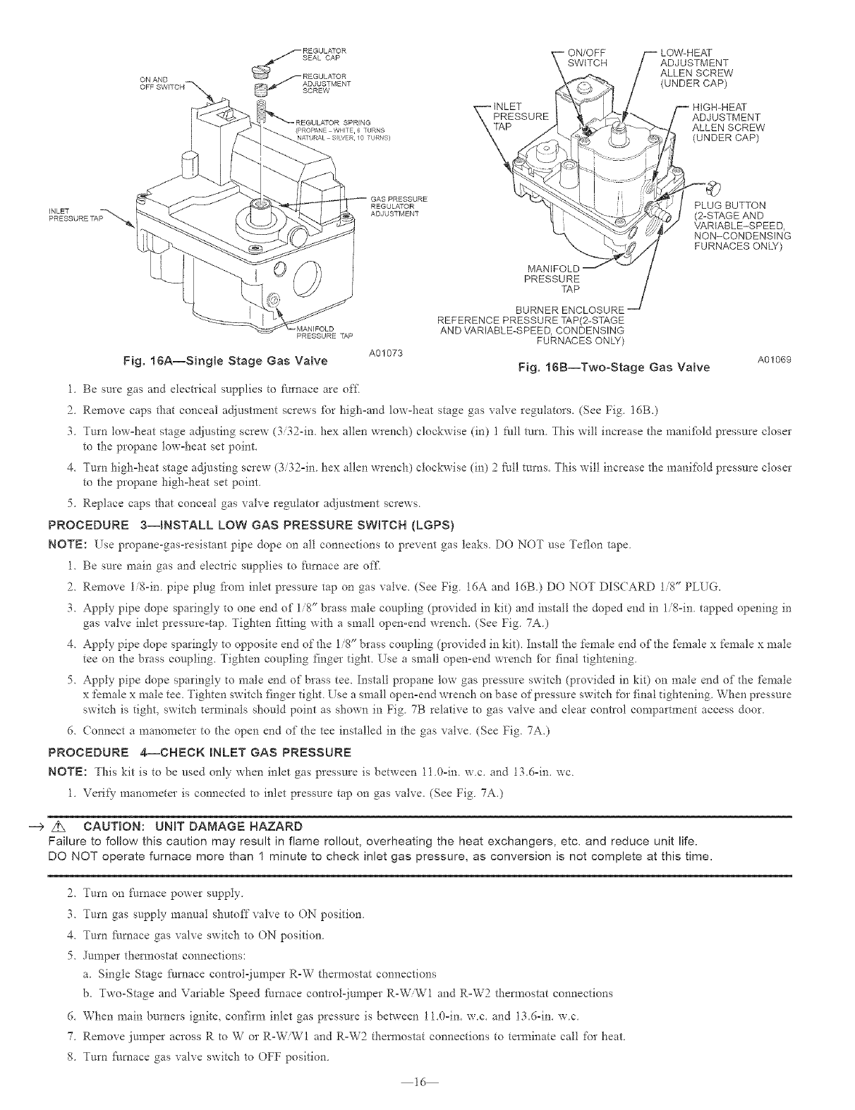
Fig. 16A--Single Stage Gas Valve A01073
MANIFOLD
PRESSURE
-rAP
BURNER ENCLOSURE -=J
REFERENCE PRESSURE TAP(2-STAGE
AND VARIABLE-SPEED, CONDENSING
FURNACES ONLY)
Fig, 16B--TwooStage Gas Valve A01069
1. Be sure gas and electrical supplies to furnace are off
2. Remove caps that conceal adjustment screws for highoand low-heat stage gas valve regulators. (See Fig. 16B.)
3. Turn low=heat stage adjusting screw (3/32-in. hex allen wrench) clockwise (in) 1 fidl turn. This will increase the maniJ:bld pressure closer
to the propane low-heat set point.
4. Turn high-heat stage adjusting screw (3/32-in. hex allen wrench) clockwise (in) 2full turns. This will increase the mani_bld pressure closer
to the propane high-heat set point.
5. Replace caps that conceal gas valve regulator adjustment screws.
PROCEDURE 3--_NSTALL LOW GAS PRESSURE SWITCH (LGPS)
NOTE: Use propane-gas-resistant pipe dope on all connections to prevent gas leaks. DO NO7 use Teflon tape
1. Be sure main gas and electric supplies to furnace are offi
2. Remove li8-in, pipe plug [i'om inlet pressure tap on gas valve. (See Fig. 16A and IdB.) DO NOT DIS(ARD 1/8" PLUG.
3. Apply pipe dope sparingly to one end of 1/8" brass male coupling (provided in kit) and install the doped end in li%in, tapped opening in
gas valve inlet pressure-tap. Tighten fitting with a small open-end wrench. (See Fig. 7A.)
4. Apply pipe dope sparingly to opposite end of the 1/8" brass coupling (provided in kit). Install the female end of the _:_male x female x male
tee on the brass coupling. Tighten coupling finger tight. Use a small open-end wrench I\_r final tightening.
5. Apply pipe dope sparingly to male end of brass tee. Install propane low gas pressure switch (provided in kit) on male end of the female
x female x male tee. Tighten switch finger tight. Use a small open-end wrench on base of pressure switch for final tightening. When pressure
switch is tight, switch terminals should point as shown in Fig. 7B relative to gas valve and clear control compartment access door.
6. Connect a manometer to the open end of the tee installed in the gas valve. (See Fig. 7A.)
PROCEDURE 4--CHECKINLETGAS PRESSURE
NOTE: This kit is to be used only when inlet gas pressure is between 11.0=in, w.c. and 13.6=in, wc.
1, Ve*ify manometer is connected to inlet pressure tap on gas valve, (See Fig 7A,)
--> z_ CAUTION: UNIT DAMAGE HAZARD
Failure to follow this caution may result in flame rol!out, overheating the heat exchangers, etc, and reduce unit life.
DO NOT operate furnace more than 1 minute to check inlet gas pressure, as conversion is not complete at this time,
2. Turn on Ihrnace power supply
3. Turn gas supply manual shutoff valve to ON position
4. Turn _i/rnace gas valve switch to ON position
5. Jumper thermostat connections:
a Single Stage farnace control-juniper R-W thermostat connections
b. Two-Stage and Variable Speed furnace control-jumper R-W/W1 and R-W2 thermostat connections
6. When main burners ignite, confirm inlet gas pressure is between 11.0=in. wc. and 13.6-in. wc
7. Remove jmnper across R to W or R-W/W1 and R-W2 thermostat connections to terminate call for heat
8. Turn _i/rnace gas valve switch to OFF position
16
9 TurngassupplymanualshutoffvalvetoOFFposition.
10.Turnofffurnacepowersupply.
1i. Removemanometer.
12.Applypipedopesparinglytoendofinletgaspipeplugandinstallinunusedendof 1/8"tee.Useasmallback=upwrenclaonteewhen
tighteninggasinletpipeplug.(SeeFig.7A.)
PROCEDURE 5--MODIFY PRESSURE SWITCH WIRING
A. Single Stage Pressure Switch Wiring
I. Disconnect yellow wire ii'om the N.O. contact of the pressure switch PRS on the inducer housing and connect it to the N.O. terminal on
the low gas pressure switch, LGPS.
2. Connect the insulated straight terminal of the 1d-in. yellow wire (provided in kit) to the C terminal on the tow gas pressure switch, LOPS.
3. Connect insulated flag terminal of 16=in. yellow wire to the N.O. terminal to pressure switch PRS located on inducer laousing.
4. Route yellow wires along wire harness.
5. Secure with wire tie provided in kit. Go to Procedure 6.
B. Two-Stage and Variable Speed Pressure Switch Wiring
1 Disconnect yellow wire fl'om low-heat pressure switch LPS on inducer housing Add 3/16=in. splice connector to this wire.
2 Connect uninsulated tem_inal of 6-in. yellow wire (provided in kit) to splice connector ( onnect other end to C terminal on low gas pressure
switch LOPS.
3 Connect insulated terminal of 14=in. yellow wire (provided in kit) to NO tem_inal on tow gas pressure switch LOPS. Connect other end to
pressure switch LPS located on inducer housing.
4. Route yellow wires along wire harness. Secure with wire tie provided in kit. Go to Procedure 6.
PROCEDURE g--CHECK FURNACE OPERATION AND MAKE NECESSARY ADJUSTMENTS
1. Be sure main gas and electric supplies to fln'nace are off
2 Remove 1/8=in. pipe plug t'rom manifold pressure tap on downstream side of gas valve (Fig 16A or 16B.)
3 Attach manometer to manifold pressure tap on gas valve (See Fig. 16A.)
4 Turn gas supply manual shutoff valve to ON position.
5 Turn l:m'nace gas valve switch to ON position.
6 Check all threaded pipe connections for gas leaks
7 Turn on fl/mace powe* supply.
Z_ VVARNJNG: FIRE, EXPLOSION, INJURY OR DEATH HAZARD
Failure to fellow this ,warning could result in fire, explosion, personal injury, or death.
NEVER use matches, candles, flame, or other sources of ignition to check for gas leakage. Use a soap-and-water solution to check
for leaks.
PROCEDURE 7--SET GAS INPUT RATE
_he gas=input rate for propane is the same as for natural gas. See t'urnace rating plate ibr input rate. _he input rate ibr propane is determined by
manifbld pressure and orifice size. Refer to the appropriate Conversion Kit Rating Plate.
Gas input rate on fl/mace rating plate is ibr installations at ahimdes up to 2000 it. In the U.S.A., the input rating for altitudes shove 2000 ft must
be reduced by 4 percent for each 1000 t't above sea level.
In Canada, the input rating must be derated by l0 percent ibr altitudes of 2000 ft to 4500 fi above sea level.
The Conversion Kit Rating Plate accounts for the high altitode derate.
A. Single Stage Furnaces
1 Jumper R and W thermostat connections to call for heat
2 Check maniibld orifices for gas leaks when main burners ignite
3 Adjust gas maniibld pressure Turn adjusting screw counterclockwise (out) to decrease manifold pressure or clockwise (in) to increase
manifbld pressure. Refer to Conversion Kit Rating Plate #327697°206 (Single-Stage).
NOTE: Gas valve regulator seal cap MUST be in place when checking input rate
4 When correct input is obtained, main burner flame should be clea* blue, almost transpa*ent (See Fig. 28) Be su*e regulator seal cap is in
place when finished
5. Remove jumper across R and W thermostat connections to terminate call ibr heat.
6. Turn furnace gas valve control switch or control knob to OFF position.
7. Turn off fl/mace power supply.
17
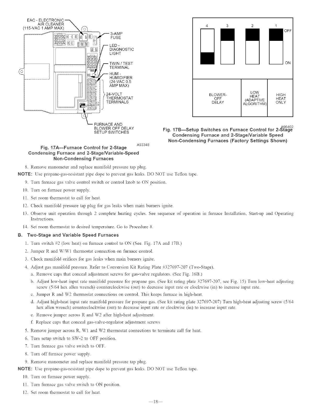
EAC - AiR CLEANER
(115-VAC I AMP MAX)
,,-- 3-AMP
FUSE
-- LED -
DIAGNOSTIC
LIGHT
-- TWIN /TEST
TERMINAL
-- HUM -
HUMIDIFIER
(24-VAC 0.5
AMP MAX)
24-VOLT
THERMOSTAT
TERMINALS
-- FURNACE AND
BLOWER OFF DELAY
SETUP SWITCHES
1
OFF
m ON
BLOWER-
OFF
DELAY
LOW
HEAT
(ADAPTIVE
ALGORITHM
HIGH
HEAT
ONLY
A96402
Fig, 17B--Setup Switches on Furnace Control for 2oStage
Condensing Furnace and 2oStage/Variable Speed
Non-Condensing Furnaces (Factory Settings Shown)
18
A93348
Fig. !7A--Furnace Control for 2oStage
Condensing Furnace and 2oStage/VadableoSpeed
Non-Condensing Furnaces
8, Remove manometer and replace mani%ld pIessure tap plug
NOTK: Use propane-gas-resistant pipe dope to prevent gas leaks, DO NOT use ]Teflon tape,
9. _urn I:k/rnace gas valve contlol switch or control knob to ON position.
10. Turn on t'nmace power supply.
11. Set room thermostat to call for heat
12. (hock manifold pressure tap plug for gas leaks when main burners ignite.
13. Observe unit operation through 2 complete heating cycles. See sequence of operation in fi/mace Installation, Start=up and Operating
][nstluctions
14. Set room thermostat to desired temperature. Go to Procedure 8.
B. Two-Stage and VarMbIe Speed Furnaces
1, _urn switch #2 (low heat) on [_/mace contlol to ON (See Fig 17A and 17B,)
2, Jumper R and WWl thermostat connection on fllrnace contlol
3. Check manifold orifices %r gas leaks when main burners ignite.
4. Adjust gas manitbld pressure. Refkr to Conversion Kit Rating Plate #327697=207 (Two=Stage).
a. Remove caps that conceal adjustment screws for gas-valve regulators. (See Fig. IdB.)
b. Adjust low=heat input rate manifold pressure for propane gas. (See kit rating plate 327697=207, see Fig. 15) Turn tow=heat adjusting
screw (5/64 hex allen wrench) counterclockwise (out) to decrease input rate or clockwise (in) to increase input rate.
c. Jumper R and W2 thermostat connections on control. This keeps J:i/mace in high-heat.
d. Adjust high=heat input rate manit'old pressure %r propane gas. (See kit rating plate 327697-207) Turn high=heat adjusting screw (5/64
hex allen wrench) counterclockwise (on0 to decrease input rate or clockwise (in) to increase input rate.
e. Remove jumper across R and W2 after high=heat adjustment.
fl Replace caps that conceal gas=valve=regulator aduustment screws
5. Remove jumper across R, W1 and W2 thermostat connections to tem_inate call %r heat.
6. Turn setup switch to SW=2 to OFF position.
7. Turn Nmace gas valve switch to OFF.
8. Turn off flu'nace power supply.
9. Remove manometer and replace manKbld pressure tap plug.
NOTE: Use propane-gas-resistant pipe dope to prevent gas leaks. DO NOT use Teflon tape.
10. Turn on [_urnace power supply.
11. Turn fl/rnace gas valve switch to ON position.
12. Set room thermostat to call for heat.
13Checkpressuretapplug%r gas leaks when main burners ignite
14 When cmTect input is obtained, main burner flame should be clear blue, ahnost transparent. (See Fig 28.)
15. Observe unit operation through 2 complete heating cycles. See sequence of operation in furnace Installation, Start-Up, and Operating
Instructions
16 Set room thermostat to desired temperature Go to Procedure 8.
PROCEDURE 8--CHECK LOW GAS PRESSURE SW{TCH OPERATION
_he newly installed tow gas pressure switch is a safety device used to guard against adveIse burner opeiating characteIistics that can result flora
low gas supply pressure, Switch opens at not tess than 6,5"w c and closes at no greater than 10,2"w,c
This switch also prevents operation when the propane tank level is low which can resuh in gas with a high concennation of impurities, additives,
and residues that have settled to the bottom of the tank Operation under these conditions can cause ha*m to the heat exchanger system This
normally open switch closes when gas is supplied to gas valve under normal operating pressure The closed switch completes control circuit,
Should an intemlption or reduction in gas supply occur, the gas pressure at switch &ops below low gas pressure switch setting, and switch opens,
Any intern/ption in control circuit (in which tow gas pressure switch is wired) quickly closes gas valve and stops gas flow to burners,
When normal gas pressure is restored, the system must be electrically reset to reestablish normal heating operation. Before leaving installation,
obserce unit ope*ation through 2 complete heating cycles During this time, turn gas supply to gas valve off just long enough to completely
extinguish burner flame, then instantly restore 5dl gas supply. To ensure proper low gas pressure switch operation, observe that there is no gas
supply to burners until alter hot sur_:hce igniter begins glowing.
PROCEDURE 0--LABEL APPLICATION (SEE FIG, 12A AND 12B)
1, Fill in Conveision Responsibility Label (327697-205) and apply to inside of furnace as shown, Date, nam< and address of organization
making this conversion are required,
2 Attack* (onversion Rating Plate Label # 327697-206 (Single-Stage) or #327697-207 (Two-Stage) near existing furnace rating plate
3 Apply Gas Cont*ol Conversion Label:
a, For single-stage gas valve apply 1abel 327697-203 to gas valve, (Do not use 327697-202, which is similar)
b For two-stage gas valve apply 1abet 327697-202 to gas valve, (Do not use 327697-203, which is similar)
19
INSTALLAT{ON
SECTION 3- D_RE( T-¥ENT, MULTIPO_SE, HOT-SURFACE _GNIT_ON, SIN(;LE-STAGE, T_VO-STAGE AND VARiABLE-SPEED
CONDENSING F! RNACES
58MXA
58M(A
58MSA
SINGLE STAGE MODELS
350MAV PG9MAA
340MAV 490AAV
345MAV
TWO-STAGE MODELS
58MTA 352MAV
VARIABLE SPEED MODELS
58MVP 355MAV
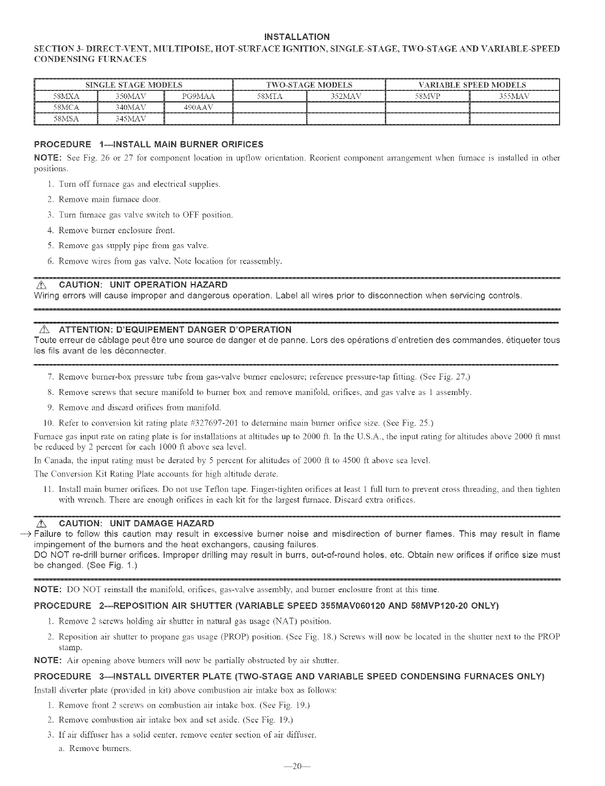
PROCEDURE I--INSTALL MAIN BURNER ORIFICES
NOTE: See Fig 26 or 27 for component location in upflow orientation_ Reorient component arrangement when farnace is installed in other
positions
1_ Turn off furnace gas and electrical supplies_
2. Remove main fl/rnace door.
3. Turn ihmace gas valve switch to OFF position.
4. Remove burner enclosure front.
5. Remove gas supply pipe fi'om gas valve.
6. Remove wires fiom gas valve. Note location for reassembly.
z_ CAUTION: UNiT OPERATION HAZARD
Wiring errors will cause improper and dangerous operation. Label all wires prior to disconnection when servicing controls.
z_ ATTENTmON: D'EQUJPEMENT DANGER D'OPERATION
Toute erreur de c_blage peut 6tre une source de danger et de panne. Lors des operations d'entretien des commandes, etiqueter tous
les ills avant de les deconnecter.
% Remove burner°box pressure robe from gas-valve burner enclosure; reJ:_rence pressure-tap fitting (See Fig. 27)
8_ Remove screws that secure manifbld to burner box and remove mania:bid, orifices, and gas valve as 1 assembly_
9. Remove and discard orifices fiom manifold.
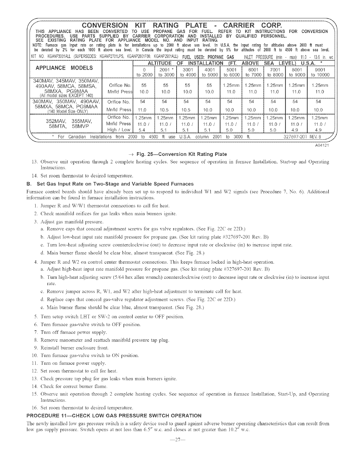
10. Refer to conversion kit rating plate #327697-201 to detem_ine main burner orifice size. (See Fig. 25.)
Furnace gas input rate on rating plate is for installations at altitudes up to 2000 it. In the U.S.A, the input rating _:br altitudes above 2000 R mnst
be reduced by 2percent tbr each 1000 k above sea level.
In Canada, the input rating must be derated by 5 percent tbr altitudes of 2000 t_ to 4500 R above sea level.
The (onversion Kit Rating Plate accounts tbr high altitude derate.
11. Install main burner orifices. Do not use Teflon tape. Finger°tighten orifices at least 1 fhll mm to prevent cross threading, and tiaen tighten
with wrench. There are enough orifices in each kit for the largest furnace. Discard extla orifices.
z_ CAUTION: UNiT DAMAGE HAZARD
--> Failure to follow this caution may result in excessive burner noise and misdirection of burner flames. This may result in flame
impingement of the burners and the heat exchangers, causing failures.
DO NOT re-drill burner orifices. Improper drilling may result in burrs, out-of-round holes, etc. Obtain new orifices if orifice size must
be changed. (See Fig. 1.)
NOTE: DO NOT reinstall the mani%ld, orifices, gas-valve assembly, and burner enclosure liont at this time
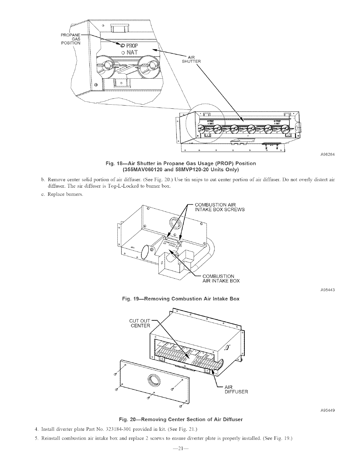
PROCEDURE 2--REPOSITION AIR SHUTTER {VARIABLE SPEED 355MAV060120 AND 58MVP120-20 ONLY)
1. Remove 2 screws holding air shutter in natnral gas usage (NAT) position.
2. Reposifion air shutter to propane gas usage (PROP) position. (See Fig. 18.) Screws will now be located in the shutter next to the PROP
stamp,
NOTE: Air opening above burners will now be paItially obstructed by air shutter
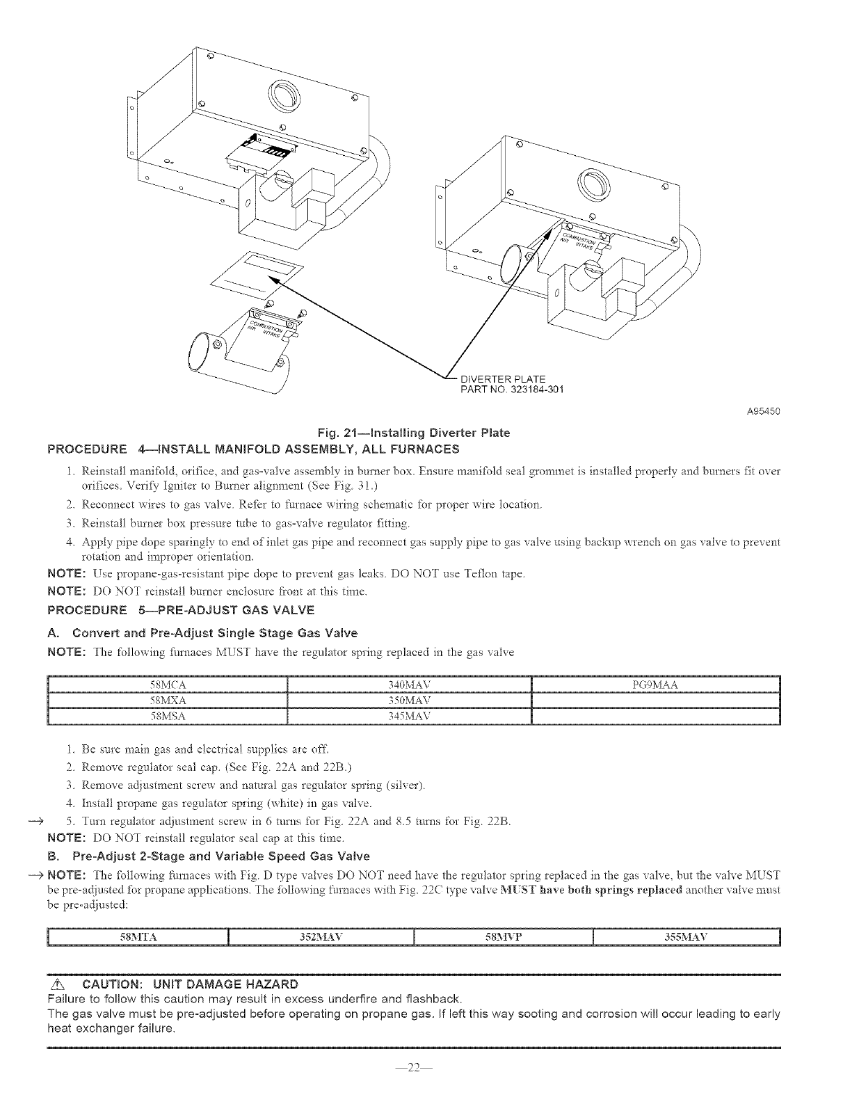
PROCEDURE 3--INSTALL DIVERTER PLATE (TWO-STAGE AND VARIABLE SPEED CONDENSmNG FURNACES ONLY)
Install diverter plate (provided in kit) above combustion air intake box as follows:
1. Remove fi'ont 2screws on con_bustion air intake box. (See Fig. 19.)
2. Remove combustion air intake box and set aside. (See Fig. 19.)
3. If air diffl/ser has a solid center, remove center section of air difft_ser.
a Remove burners
2O
GAS
POSITION P_0P
oNAT AIR
SHUTTER
A96264
Fig. 18--Air Shutter in Propane Gas Usage (PROP) Position
(355MAV060120 and 58MVP120-20 Units Only)
b Remove centeI solid portion of air difthser. (See Fig. 20) Use tin snips to cut center portion of air difthser, Do not overly distort air
di£[i/ser, The air dif[hser is Tog=L-Locked to burner box,
c. Replace burners.
AIR
iNTAKE BOX SCREWS
_/ AIR iNTAKE BOX
Fig, 19--Removing Combustion Air mntake Box
A95443
CUT
CENTER
Fig. 20--Removing Center Section of Air Diffuser
4 Install di_erter plate Part No 323184-301 provided in kit (See Fig. 2!)
5. Reinstall combustion air intake box and replace 2screws to ensure diverter plate is properly installed, (See Fig. 19.)
21
A95449
DIVERTER PLATE
PART NO. 323184-301
A95450
Fig. 21--Installing Diverter Plate
PROCEDURE 4--INSTALL MANBFOLD ASSEMBLY, ALL FURNACES
1. Reinstall manifbld, orifice, and gas-valve assen_bly in burner box. Ensme mani%ld seal grommet is installed properly and burners fit over
orifices. Verify Igniter to Burner alignment (See Fig 31.)
2. Reconnect wires to gas valve. Refkr to fi_rnace wiring schematic %r proper wire location.
3. Reinstall burner box pIessure robe to gas-valve regulator fitting.
4, Apply pipe dope sparingly to end of inlet gas pipe and reconnect gas supply pipe to gas valve using backup wrench on gas valve to prevent
rotation and improper orientation.
NOTE: Use propane-gas-resistant pipe dope to prevent gas leaks, DO NOT use Teflon tape,
NOTE: DO NOT reinstall burner enclosure fi'ont at this time,
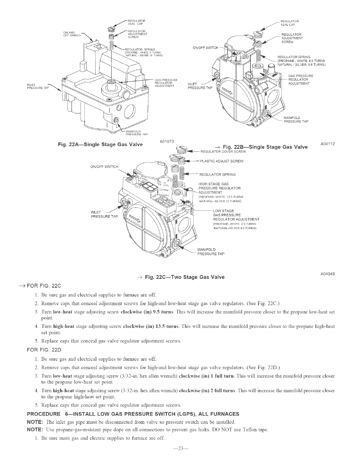
PROCEDURE 5--PRE-ADJUST GAS VALVE
A, Convert and Pre-Adjust Single Stage Gas Valve
NOTE: The following fl/rnaces MLST have the regulator spring replaced in the gas xahe
58MCA
58MXA
58MSA
340MA\
350MAV
345MA\
PG9MAA
1, Be sure main gas and electrical supplies are of£
2, Remove regulator seal cap, (See Fig. 22A and 22B,)
3, Remove acljustment screw and natural gas regulator spring (silver),
4, Install propane gas regulator spring (white) in gas valve,
--9 5, Turn regulator adjustment screw in 6 rams for Fig 22A and 85 rams for Fig 22B
NOTE: DO NOT reinstall regulator seal cap at this time,
B, Pre°Adjust 2°Stage and Variable Speed Gas Valve
---> NOTE: The fbllowing furnaces with Fig D type valves DO NOT need have the regulator spring replaced in the gas valvQ but the vah-e MUST
be pre-adjusted fbr propane applications, The following [_urnaces with Fig. 22(; type vah*e MUST have both springs replaced another valve must
be pre-adjusted:
5gMTA I 352MA_ I 5gM_P [ 3S.gMAV
z_ CAUTION: UNIT DAMAGE HAZARD
Failure to follow this caution may result in excess underfire and flashback.
The gas valve must be pre-adjusted before operating on propane gas. If left this way sooting and corrosion will occur leading to early
heat exchanger failure,
22
REGULATOR
(PROPANE WHITE 6 TJRNS
NAIURAL SID/ER _0 TURNS)
REGULATOR
ADJUSTMENT
SCREW
REGULATOR SPRING
(PROPANE - WHITE, 85 TURNS
NATURAL -S_LVER, 85 TURNS)
GAS PRESSURE
GAS PRESSURE
REGULATOR iNLET _ ADJUSTMENT
ADJUSTMENT PRESSURETAP
MAN_FOLD
PRESSURETAP
PRESSURE lAP
Fig. 22A--Single Stage Gas Valve
ON/OFF SWITCH
INLET
PRESSURETAP
\
\
A01073
_ --> Fig, 22B--Single Stage Gas Valve
REGULATOR COVER SCREW
_PLASTfC ADJUST SCREW
REGULATOR SPRING
HiGH STAGE GAS
PRESSURE REGULATOR
(PROPANE WHITE /3 5 THRNS
NATURAL S_LVER,_2 TURNS)
GAS PRESSURE
REGULATOR ADJUSTMENT
(PROPANE WHITE 9 5 TURNS
NATURAL SILVFR,9 5 TURNS)
MAN_FOLD
_PRESSURE TAP
A04112
Fig. 22C--Two Stage Gas Valve A04048
--> FOR FIG, 22C
1 Be sm'e gas and electrical supplies to/;_/rnace are off.
2. Remove caps that conceal adjustment screws [br high-and low-heat stage gas valve regulators. (See Fig. 22(.)
3. Turn low-heat stage adjusting screw clockwise (in) 9.5 turns. This will increase the manifold pressure closer to the propane tow-heat set
point.
4. Turn high-heat stage a_iusting screw clockwise (in) 13.5 tm'ns. This will increase the manifold pressure closer to the propane high-heat
set point.
5. Replace caps that conceal gas valve regulator adjustment screws.
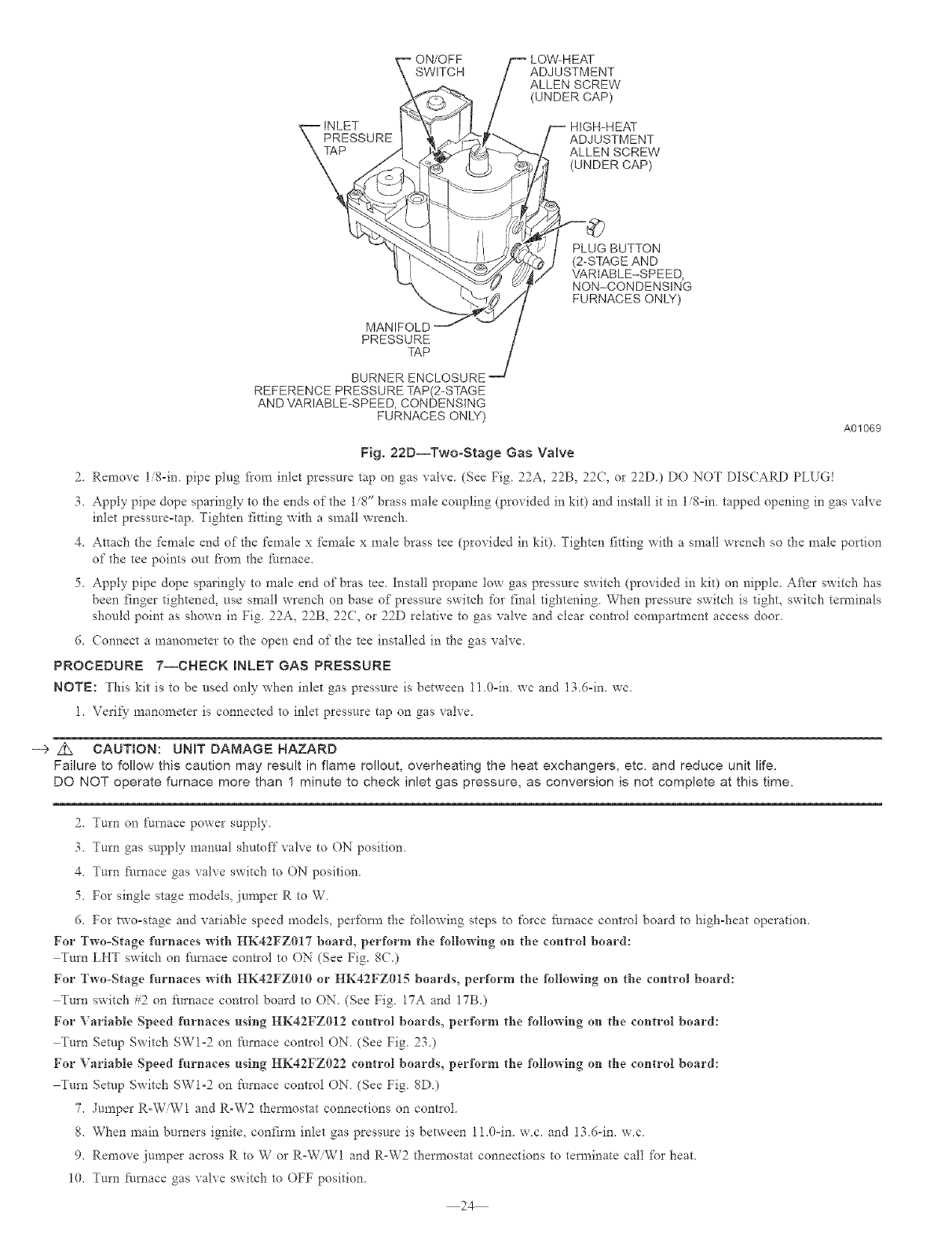
FOR FiG. 22D
I. Be sure gas and electrical supplies to fl/mace are off.
2. Remove caps that conceal adjustment screws fbr high-and low-heat stage gas valve regulators. (See Fig. 22D.)
3. Turn lew-l_eat stage adjusting screw (3/32-im hex allen wrench) clockwise (in) 1 Nil turn. This will increase the manifold pressure closer
to the propane tow-heat set point.
4. Turn high-heat stage adjusting screw (3/32-in. hex allen wrench) clockwise (in) 2 full turns. This will increase the manifbld pressure closer
to the propane high-heat set point.
5. Replace caps that conceal gas valve regulator adjustment screws.
PROCEDURE 6--INSTALL LOW GAS PRESSURE SWITCH (LGPS), ALL FURNACES
NOTE: The inlet gas pipe must be disconnected t?om valve so pressure switch can be installed
NOTE: Use propane-gas-resistant pipe dope on all connections to prevent gas leaks DO NOT use Teflon tape.
1. Be sure main gas and electric supplies to fire, ace are off
23
"__EINLET
SSURE
MANIFOLD
PRESSURE
_P
BURNER ENCLOSURE
REFERENCE PRESSURETAP(2-STAGE
ANDVARIABLE-SPEED, CONDENSING
FURNACES ONLY)
Fig. 22D--Two-Stage Gas Valve
ADJUSTMENT
ALLEN SCREW
(UNDER CAP)
--HIGH-HEAT
ADJUSTMENT
ALLEN SCREW
(UNDERCAP)
PLUG BUTTON
(2-STAGEAND
VARIABLE-SPEED,
NON-CONDENSING
FURNACES ONLY)
A01069
--> Z_ CAUTION: UN{T DAMAGE HAZARD
Failure to follow this caution may result in flame rol!out, overheating the heat exchangers, etc, and reduce unit life.
DO NOT operate furnace more than 1 minute to check inlet gas pressure, as conversion is not complete at this time,
2. Turn on furnace power supply
3. Turn gas supply manual shutoff valve to ON position
4. Turn furnace gas valve switch to ON position
5. For single stage models, jumper R to W.
6. For two-stage and variable speed models, perfbm_ the following steps to force furnace control board to high-heat operation.
For Two-Stage furnaces with HK42FZ917 board, perforru the following on the control board:
Turn LHT switch on fhmace contlol to ON (See Fig. 8C.)
For Two-Stage furnaces with HK42FZ919 or HK42FZO15 boards, perform the following on the control board:
Turn switch #2 on furnace contIol board to ON. (See Fig. 17A and 17B.)
For Variable Speed furnaces using HK42FZ012 control boards, perform the follo_ving on the control board:
Turn Setup Switch SW1-2 on [_urnace control ON. (See Fig. 23.)
For Variable Speed furnaces using HK42FZ022 control boards, perform the following on the control board:
Turn getup Switch SW1-2 on [_urnace control ON. (See Fig. 8D.)
7. Jumper R-W/W1 and R-W2 them_ostat connections on conhol.
8. When main burners ignite, confirm inlet gas pressure is between 11.0-in. w.c. and 13.6qn. w.c.
9. Remove jumper across R to W or R-W/W1 and R-W2 thermostat connections to terminate call for heat.
10. Turn fhmace gas valve switch to OFF position.
24
2. Remove 1/8-in. pipe plug from inlet pressure tap on gas valve. (See Fig. 22A, 22B, 22(, or 22D.) DO NOT DISCARD PLUG!
3. Apply pipe dope sparingly to the ends of the 1/8" brass male coupling (provided in kit) and install it in li8-in tapped opening in gas valve
inlet pressure-rap Tighten fitting with a small wrench
4. Attach the female end of the female x female x male brass tee (provided in kit) Tighten fitting with a small wrench so the male portiou
of the tee points out fi'om the furnace.
5. Apply pipe dope sparingly to male end of bras tee. Install propane tow gas pressure switch (provided in kit) on nipple. After switch has
been finger tightened, use small wrench on base of pressure switch for final tightening. When pressure switch is tight, switch terminals
should point as shown in Fig. 22A, 22B, 22C, or 22D relative to gas valve and clear contloi compartment access door.
6. Connect a manometer to the open end of die tee installed in the gas valve.
PROCEDURE 7--CHECK INLET GAS PRESSURE
NOTE: This kit is to be used ouly when inlet gas pressure is between 11 0-iu wc and 13.6-in. wc.
1. Verify manometer is connected to inlet pressure tap on gas valve,
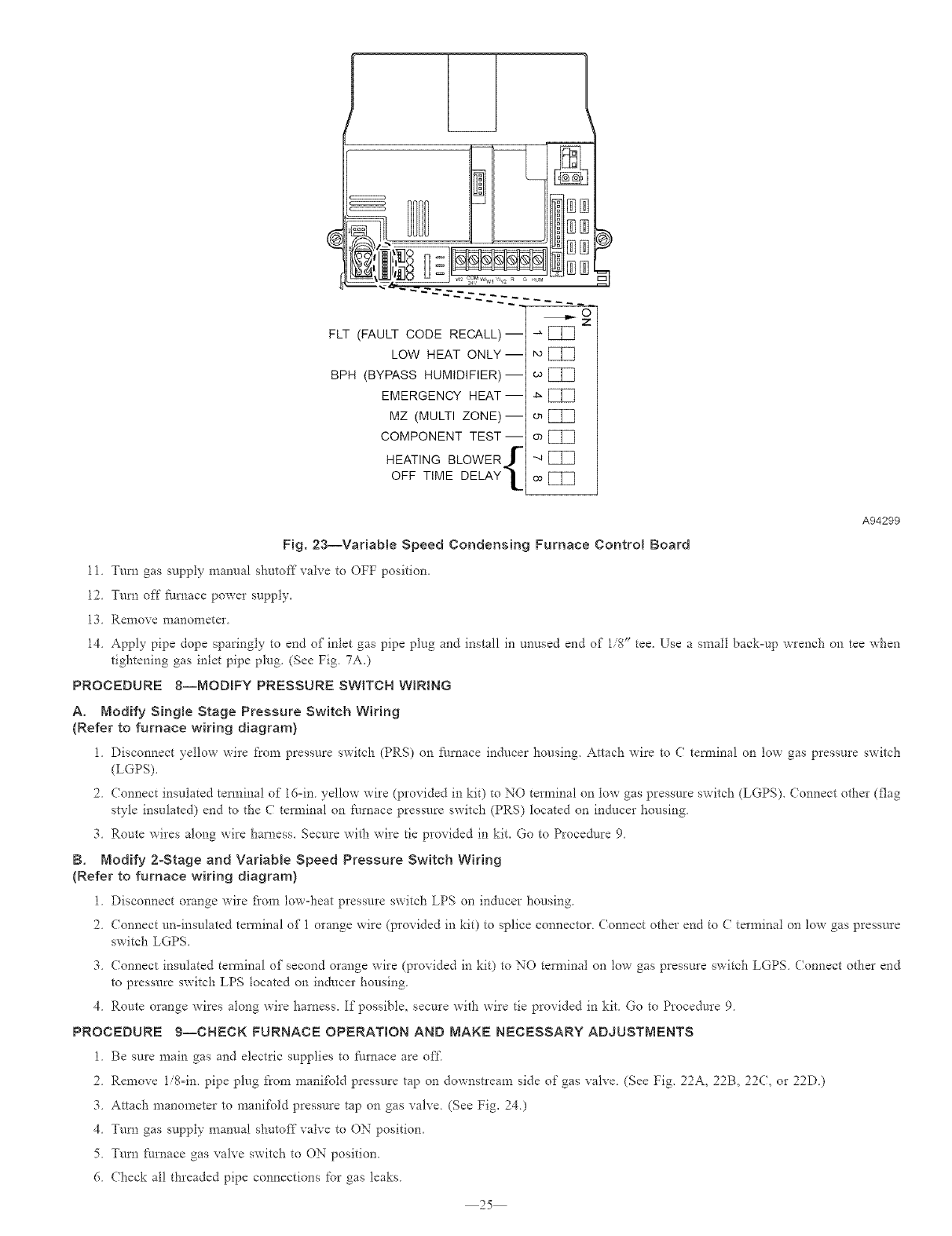
FLT (FAULT CODE RECALL)-
LOW HEAT ONLY--
BPH (BYPASS HUMIDIFIER)-
EMERGENCY HEAT--
MZ (MULTI ZONE)-
COMPONENT TEST-
HEATING BLOWER I
OFF TIME DELAY L
EI3
EIE]
o_ []]Ill
o_ []]Ill
"_ []]Ill
co hill
A94299
Fig. 23--Variable Speed Condensing Furnace Control Board
11 Turn gas supply manual shutoff" valve to OFF position,
12. Turn off fllmace power supply,
13. Remove manometer.
14. Apply pipe dope sparingly to end of inlet gas pipe plug and install in unused end of 1/8" tee, Use a small back=up wrench on tee when
tightening gas inlet pipe plug. (See Fig. 7A.)
PROCEDURE 8--MODIFY PRESSURE SWITCH WIRING
A, Modify Single Stage Pressure SwRch Wiring
{Refer to furnace wiring diagram)
1 Disconnect yellow wire from pressure switch (PRS) on flul_ace inducer housing. Attach wire to C tem_inal oil tow gas pressure switch
(LGPS).
2. Connect insulated tem_inal of 16=in. yellow wire (provided in kit) to NO terminal on tow gas pressure switch (LGPS). ( oanect other (flag
style insulated) end to tlae C terminal on [:umace pressure switch (PRS) located on inducer housing.
3. Route wires along wire harness. Secure with wire tie provided in kit. Go to Procedure 9.
B, Modify 2-Stage and Variable Speed Pressure Switch Wiring
{Refer to furnace wiring diagram)
1 Disconnect orange wire fi'om lowqLeat pressure switch LPS oil inducer housing
2. Connect un-insulated terminal of I orange wire (provided in kit) to splice connector. Connect otl_er end to C terminal on low gas pressure
switch LGPS.
3. Connect insulated terminal of second orange wire (provided in kit) to NO terminal on low gas pressure switch LGPS. Connect other end
to pressure switch LPS located on inducer housing.
4. Route orange wires along wire laamess. If possiblQ secure with wire tie provided in kit. Go to Procedure 9.
PROCEDURE 9--CHECK FURNACE OPERATION AND MAKE NECESSARY ADJUSTMENTS
1. Be sure main gas and electric supplies to flu'nace are off
2 Remove 1i%im pipe plug from manifold pressure tap on downstream side of gas valve (See Fig. 22A, 22B, 22(, or 22D)
3 Attach manometer to manifold pressure tap on gas valve (See Fig. 24)
4 Turn gas supply manual shutoff'valve to ON position.
5 Turn _:m'nace gas valve switch to ON position,
6. Check all threaded pipe connections for gas leaks.
25
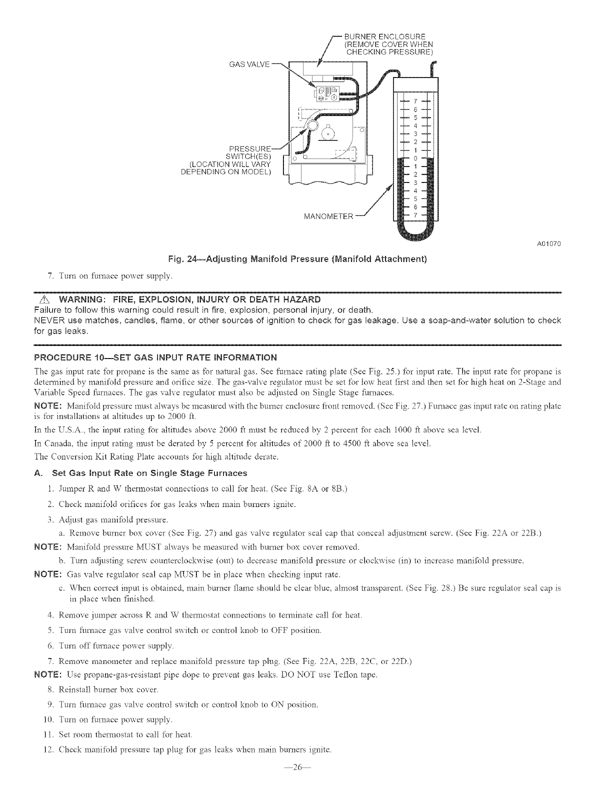
GAS VALVE
(REMOVE COVER WHEN
CHECKING PRESSURE)
PRESSURE i-_
SWITCH(ES)
(LOCATION WILL 'VARY
DEPENDING ON MODEL)
MANOMETER
Fig. 24--Adjusting Manifold Pressure {Manifold Attachment)
7, Turn on Jim, ace power supply
A01070
z_ WARNING: FIRE, EXPLOSION, raNJURY OR DEATH HAZARD
Failure to follo\,v this warning could result in fire, explosion, personal injury, or death.
NEVER use matches, candies, flame, or other sources of ignition to check for gas leakage. Use a soap-and-water solution to check
for gas leaks.
PROCEDURE 10--SET GAS BNPUT RATE mNFORMAT_ON
The gas input rate fbr propane is the same as for natural gas. See furnace rating plate (See Fig. 25.) fbr input rate. The input rate _br propane is
detem_ined by manii;old pressure and orifice size The gas=valve regulator must be set for tow heat first and then set _br high heat on 2=Stage and
Variable Speed t'umaces. The gas valve regulator must also be adiusted on Single Stage fllmaces.
NOTE: Manifold pressure mnst always be measured wit}* the burner enclosure fiont removed. (See Fig. 275 Furnace gas input rate on rating plate
is for installations at altitudes up to 2000 ft.
In the U.S.A, the input rating _br altitudes above 2000 fi must be reduced by 2 percent for each i000 t't above sea level.
In Canada, the input rating must be derated by 5 percent _br ahitudes of 2000 k to 4500 ft above sea level.
The (onversion Kit Rating Plate accounts _br high altitude derate.
A. Set Gas Input Rate on Single Stage Furnaces
1. Jumper R and W them_ostat connections to call [brheat. (See Fig 8A or 8B.)
2. Check manifold orifices for gas leaks when main burners ignite.
3. Ac_iust gas mani_bld pressure.
a. Remove burner box cover (See Fig. 27) and gas valve regulator seal cap that conceal adjustment screw. (See Fig. 22A or 22B.)
NOTE: Manifold pressure MUST always be measured with burner box cover removed.
b. Turn adjusting screw counterclockwise (out) to decrease mani[bld pressure or clockwise (in) to increase mani_bld pressure.
NOTE: Gas valve regulator seal cap MUST be in place when checking input rate.
c. When con'ect input is obtaine& main burner flame should be clear blue, almost transparent. (See Fig. 28.) Be sure regulator seal cap is
in place when finished.
4. Remove jumper across R and W them_ostat connections to tem_inate call fbr heat
5. Tm'n fl/mace gas valve control switch or control knob to OFF position.
6. Turn off fl_rnace power supply
7. Remove manometer and replace maniibld pressure tap plug (See Fig. 22A, 22B, 22(, or 22D)
NOTE: Use propane-gas-resistant pipe dope to prevent gas leaks DO NOT use Teflon tape.
8. Reinstall burner box cover.
9. Tm'n fl/mace gas valve contlol switch or control knoh to ON position.
10. Turn on furnace power supply
1l. Set room thermostat to call for heat
12. (heck manifold pressure tap plug for gas leaks when main burners ignite
26
CONVERSmON KmT RATING CARRmER CORP. -_
THIS APPLIANCE HAS BEEN CONVERTED TO USE PROPANE GAS FOR FUEL, REFER TO KiT iNSTRUCTiONS FOR CONVERSION
PROCEDURES, USE PARTS SUPPMED BY CARRIER CORPORATION AND INSTALLED BY QUALiFiED PERSONNEL
SEE EXIBTNG RATING PLATE FOR APPLIANCE MODEL NO, AND iNPUT RATING,
IOTE: Furnace gas input rate on rating plate is for installationsup to 2000 ff above sea ieveL in U£,A the input rating for altitudes above 2000 ff must
be derated by 2% for each 1000 ff above sea ieve[ in Canadathe input rating must be derated by 5% for aNtudes of 2000 ff to 4500 ff above sea level
KIT NO KGANP3001ALL(SUPERSEDES:KGANP2701LPSKGANP2801F80KGANP2%1ALL)FUEL USED: PROPANEGAS
ALTITUDE OF INSTALLATION (FT.
APPLIANCE MODELS 0 2001 * 3001 4001 5001
to 2000 to 3000 to 4000 to 5000 to 6000
340MAY, 345MAV, 350MAV,
490AAV, 58MCA, 58MSA,
58MXA PG9MAA
<AllmodelsizesEXCEPT140)
340MAY, 350MAV, 490AAV,
58MXA, 58MCA, PG9MAA
(140ModelSizeONLY)
iNLETPRESSURE(rain -max): 110 -13.6 in. wl
ABOVE SEA LEVEL} U.S.A. *
6001 7001 8001 9001
to 7000 to 8000 to 9000 to 10000
Orifice No. 55 55 55 55 1.25mm 1.25mm 1.25mm 1.25mm 1.25mm
Mnfld Press 10.0 10.0 10.0 10.0 11.0 11.0 11.0 11.0 11.0
Orifice No. 54 54 54 54 54 54 54 54 54
Mnfld Press 11.0 10.5 10.5 10.0 10.0 10.0 10.0 10.0 10.0
Orifice No. 1.25mm 1.25mm 1.25mm 1.25mm 1.25mm 1.25mm 1.25mm 1.25mm 1.25mm
352MAV, 355MAV, Mnfld Press 11.0 /11.0 /11.0 /11.0 /11.0 /11.0 /11.0 /11.0 /11.0 /
58MTA, 58MVP High /Low 5.4 5.1 5.1 5.1 5.0 5.0 5.0 4.9 4.9
* For Canadian tnsta%tions from 2000 to 4500 ft U.S.A. column 2001 to 3000 ft. 327697-201 REV,B
use
A04121
Fig. 25--Conversion Kit Rating Plate
13 Observe unit operation through 2 complete heating cycles See sequence of operation in i?m'nace Installation, Start-up and Opeiating
Instructions
14. Set room d-_ermostat to desired temperature.
g. Set Gas hput Rate on Two-Stage and Variable Speed Furnaces
Furnace control boards should have already been set up to respond to individual W1 and W'2 signals (see Procedure 7, No 6) Additional
inI:bns_ation can be fbund in t_umace installation instructions.
1. Jumper R and W/W1 them?ostat connections to call fbr heat.
2. Check manil\_ld orifices for gas leaks when main burners ignite.
3. Adjust gas manifold pressure.
a. Remove caps that conceal adjustment screws fbr gas valve regulators. (See Fig. 22( or 22D.)
b. Adjust low-heat input rate manifold pressure for propane gas. (See kit rating plate #327697-20! Rev. B)
c. Turn low=heat adjusting screw counterclockwise (out) to decrease input rate or clockwise (in) to increase input rate.
d. Main burner flame should be clear blue, almost transparent. (See Fig. 28.)
4. Jumper R and W2 on control center tl",ermostat connections. This keeps furnace locked in high=heat operation.
a. Ac[iust high-heat input rate manifold pressure t'or propane gas. (See kit rating plate #327697-20! Rev. B)
b. Tuna high-heat adjusting screw (5/64 hex allen wrench) counterclockwise (out) to decrease input rate or clockwise (in) to increase input
rate.
c. Remove jumper across R, W1, and W2 after high-heat adjustment to tem_inate call fbr heat
d Replace caps that conceal gas=valve regulator adjustment screws. (See Fig. 22(7 o1"22D)
e. Main burner flame should be clear blue, almost transparent. {See Fig 28)
5 Turn setup switch LHT or SW=2 on control center to OFF position.
6 Turn t:umace gas-valve switch to OFF position.
7 Tuna oft"filmace power supply.
8 Remove manometer and reattach manifold pressure tap plug
9 Reinstall burner enclosure front
10 Turn t'umace gas-valve switch to ON position.
11 Turn on 1:i/mace powe* supply.
12 Set room thermostat to call fbr heat.
13 Check pressure mp plug fL)r gas leaks when main burners ignite
14 Check for cmTect burner flame
15 Observe unit operation through 2 complete heating cycles See sequence of operation in furnace Installation, Start-Up, and Operating
Instructions
16. Set room them?ostat to desired temperature.
PROCEDURE 11--CHECK LOW GAS PRESSURE SWITCH OPERATION
_he newly installed tow gas pressure switch is a safety device used to guard against adverse burner operating characteiistics that can result fi'om
low gas supply pressure. Switch opens at not tess than 6.5" w.c. and closes at not greater than 10.2" w.c.
27
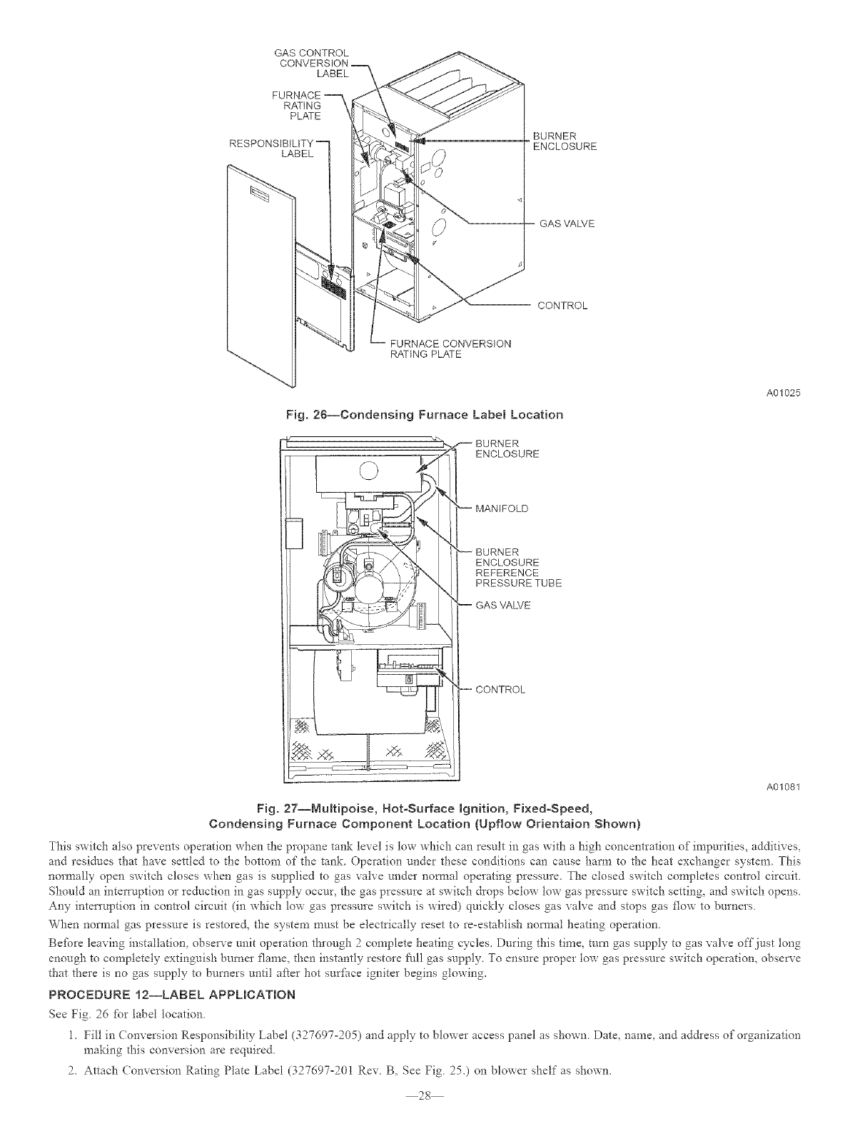
GAS CONTROL
LABEL
RATING
PLATE
LABEL
BURNER
ENCLOSURE
GAS VALVE
CONTROL
RATING PLATE
Fig. 26--Condensing Furnace Label Location
_ /--BURNER
ENCLOSURE
_MANIFOLD
_BURNER
ENCLOSURE
REFERENCE
PRESSURETUBE
--GASVALVE
--CONTROL
A01025
A01081
Fig. 27--Multipoise, Hot-Surface Ignition, Fixed-Speed,
Condensing Furnace Component Location (Upfiow Orientaion Shown)
_fhis switch also prevents operation when the propane tank level is tow which can result in gas with a high concentration of impurities, additives,
and residues that have settled to the bottom of the tank. Operation under these conditions can cause harm to the heat exchanger system. )"his
normally open switch closes when gas is supplied to gas valve under nom_al operating pressure. The closed switch completes contlol circuit.
Should an interIuption or reduction in gas supply occur, the gas pressure at switch drops below tow gas pressure switch setting, and switch opens.
Any intetTuption in control circuit (in which low gas pressure switch is wired) quickly closes gas valve and stops gas flow to burners.
When normal gas pressure is restored, the system must be electrically reset Gore-establish nom_al heating operation.
Befbre leaving installation, observe unit operation through 2complete heating cycles. During this time, mm gas supply to gas valve off just tong
enough to completely extinguish burner flame, then instantly restore f_all gas supply. To ensure proper tow gas pressure switch operation, observe
that there is no gas supply to burners until after hot surfi_ce igniter begins glowing.
PROCEDURE 12--LABEL APPLICATION
See Fig. 26 %r label location.
1. Fill in Conversion Responsibility Label (327697-205) and apply to blower access panel as shown. Date, name, and ad&ess of organization
making this conversion are required.
2. Attach Conversion Rating Plate Label (327697-201 Rev. B, See Fig. 25.) on blower shelf as shown.
28
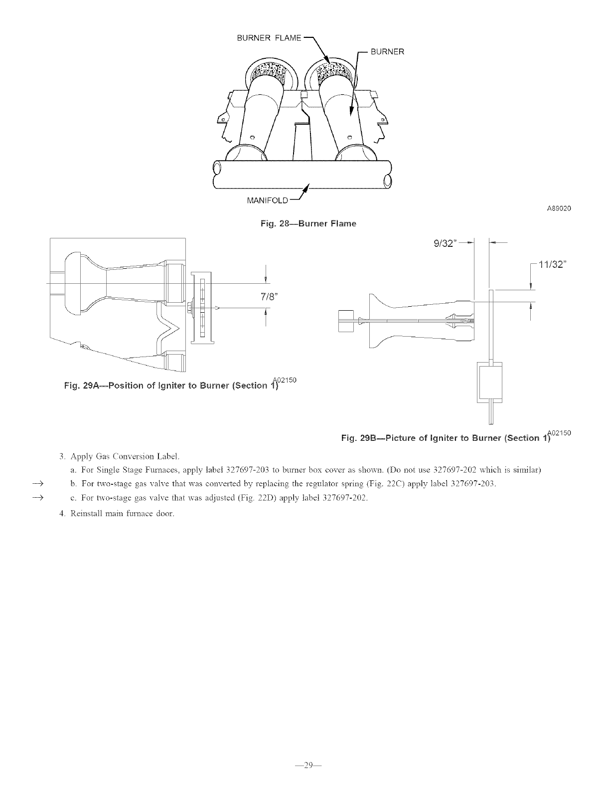
BURNER FLAME
BURNER
MANIFOLD
Fig. 28--Burner Ftame
- 7/8"
Fig. 29A--Position of Igniter to Burner (Section 1t o215o
9/32"
A89020
F I 1/32"
T
-->
-->
Fig. 29B--Picture of Igniter to Burner (Section If °215°
3 Apply Gas Conversion Label
a. For Single Stage Furnaces, apply label 327697-203 to burner box cover as shown. (Do not use 327697°202 which is similar)
b. For two-stage gas valve that was converted by replacing the regulator spring (Fig. 22(:) apply label 327097-203.
c. For two-stage gas valve that was adjusted (Fig. 22D) apply label 327097-202.
4. Reinstall main [_t_mace door.
29
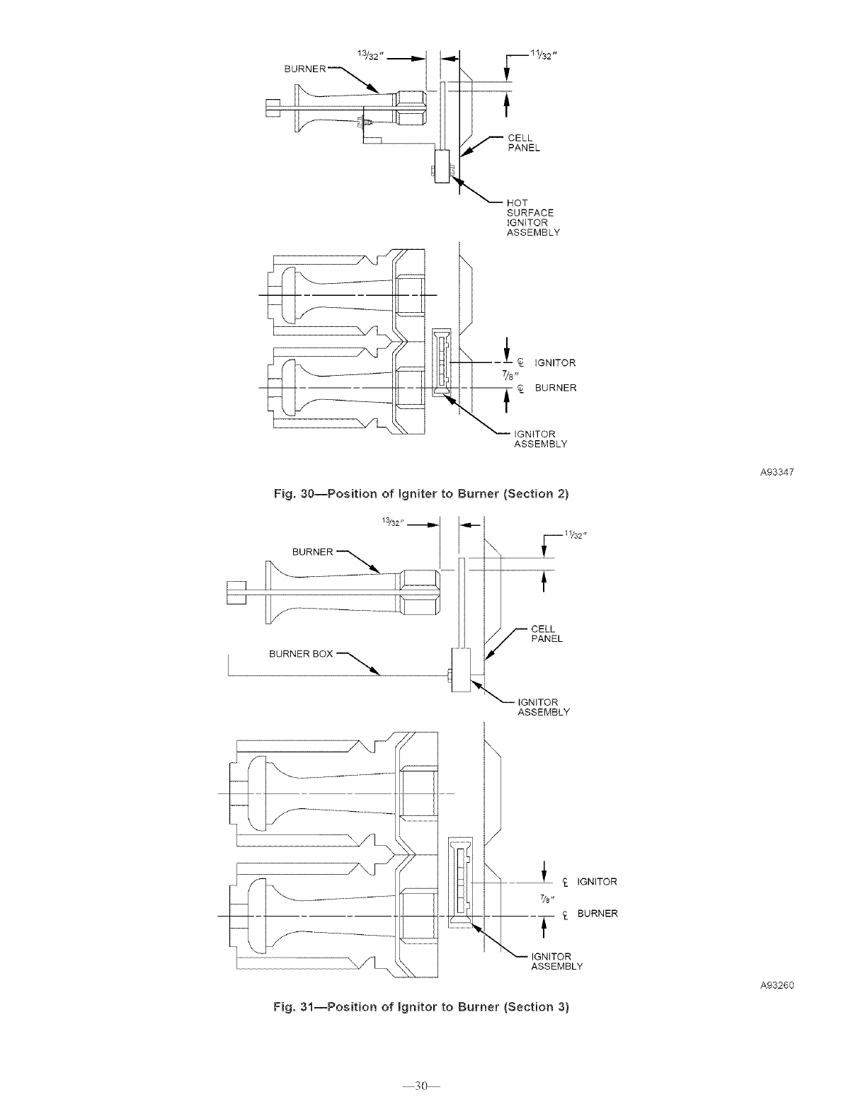
13/32" .__1,,._ I
BU___
II-__ _F _ 11/32''
_-- CELL
PANEL
_--HOT
SURFACE
IGNITOR
ASSEMBLY
P_ IGNITOR
7/8,,
--_- C_ BURNER
IGNITOR
ASSEMBLY
Fig. 30--Position of Igniter to Burner (Section 2)
BURNER BOX'*_...._
i_ _i11/32"
NITOR
ASSEMBLY
A93347
_ IGNITOR
7/8'r
BURNER
t
IGNITOR
ASSEMBLY
Fig. 31--Position of Ignitor to Burner (Section 3)
A93260
3O

31

© 2004 CAC/BDP 7310 W. Morris St, Indianapolis, IN 46231 agganp31 32 Catalog No. 63GA-NP11
