CARRIER Humidifier Manual L0512101
User Manual: CARRIER CARRIER Humidifier Manual CARRIER Humidifier Owner's Manual, CARRIER Humidifier installation guides
Open the PDF directly: View PDF ![]() .
.
Page Count: 2
)fl This product must be instaB_edby a qualified heating and air conditioning contractor.
Failure to do so, could result in serious injury from e{ectrica_ shock.
This product must be instaJJed in compliance with aH Bocal, state and federal codes.
The Small ByPass Humidifier can be installed on either the supply or return plenum of a forced air handling system.
Easy reversible installation right hand or left hand.
Read complete instructions before mounting the humidifier. The unit is 127/8"W x 123YH x 9%"D. The dimensions and serviceability must be
considered when selecting the best location for the unit.
if the furnace has central cooling, the bypass damper in the humidifier must be closed during the cooling season. Turn knob to summer setting.
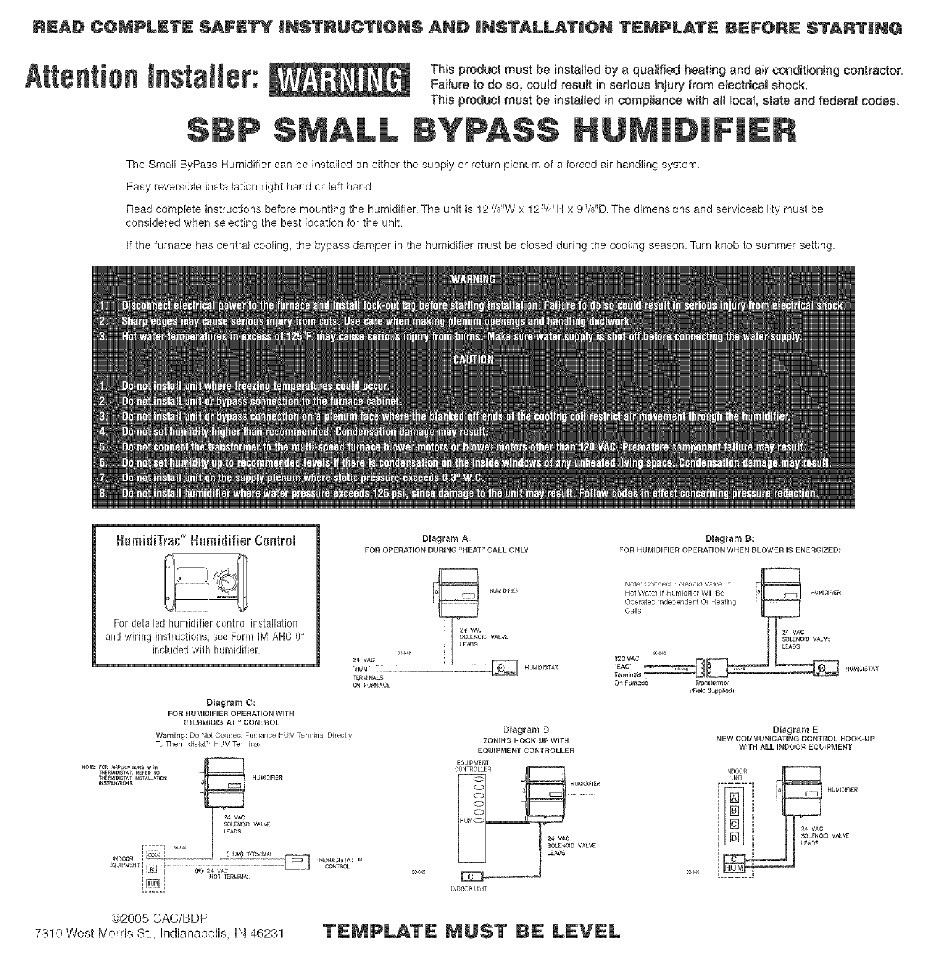
HumidiTrac'_Humidifier Control
For detailed humidifier control installation
and wiring instructi0ns_ see Form IM-AHC-01
included with humidifier.
Diagram C:
FOR NUMID_FIER OPERATION W_TH
TH ERMID_STAT _ CONTROL
Warning: Do Not Connect Furnance HDM I_nnalal Directly
Tu ThennidiNat-" Ht IM TelrDnN
r4o_E__o_ _puo_Tio_s valq_
[-----I _0B44
,t_DOORi _2__
[@_i
_ HU_;DJRER
_ VAC
SOL£_O_D VAL_
LEADS
(_) 24 vAc
HOT TERMINAL
Diagram A:
FOR OPERATION DNRING NEAT" CALL ONLY
9_ _42
24 VAO
"HUW
TERMINALS
ON £URNAOE
HUMI_I£ER
24 VAO
SOLENOID VALVE
Diagram D
ZONING HOON-NP WITH
EQN_PMENT CONTROLLER
EQUff_MENT
IND00R UNIT
24 VAC
$OL_N_D VALVE
LEADS
Diagram B:
FOR NU_DIPIER OPERATION WHEN BLOWER IS ENERGIZED:
Or_Fucr_¢$ Transl.'mac
(F_eN 8_ppt_ee)
Diagram E
NEW COM#DNICATING CONTROL HOOK-UP
WITH ALL INDOOR EQUIPMENT
INDOOR
UNiT
HtJ_ID_RER
24 VA0
SOLENOID VALVE
L£ADS
L
@2005 CAC/BDP
7310 West Morris St., Indianapolis, iN 46231 TEMPLATE UST LEVEL
TOP
READ COMPLETE SAFETY INSTRUCTIONS AND INSTALLATION TEMPLATE BEFORE STARTING
TEMPLATE MUST BE LEVEL
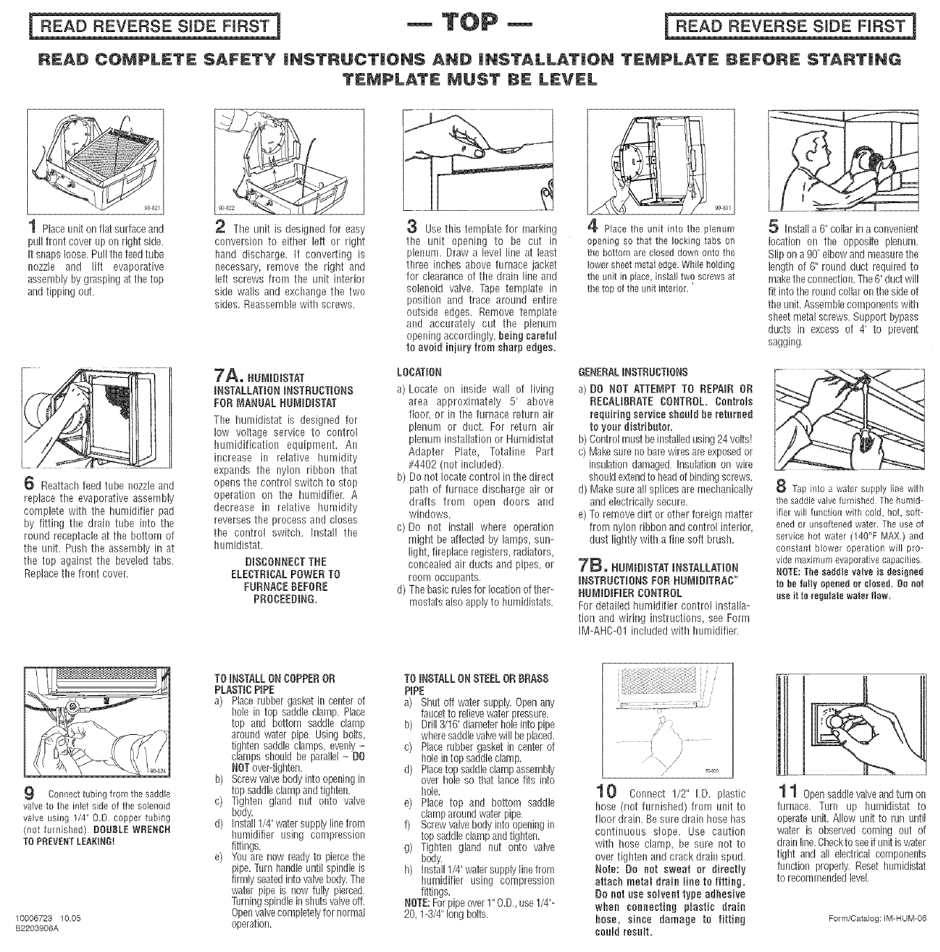
1 Placeunit on flat surface and
pull front cover lip oil right side.
it snaps loose,Pull the feed tube
nozzle and lift evaporative
assembly by grasping at the top
and tipping out.
6 Reattach feed tube nozzleand
replace the evaporative assembly
complete with the humidifier pad
by fitting the drain tube into the
round receptacle at the bottom of
the unit. Push the assembly in at
the top against the beveled tabs,
Replace the front cover.
2 The unit is designed for easy
conversion to either left or right
hand discharge. If converting is
necessary_ remove the right and
left screws from the unit interior
side walls and exchange the two
sides, Reassemble with screws.
7A. RU_D_STAT
_NSTALLAT_ONiNSTRUCTIONS
FON _IANUAL RU_OmSTAT
The humidistat is designed for
low voltage service to control
humidification equipment. An
increase in relative humidity
expands the nylon ribbon that
opens the control switch to stop
operation on the humidifier. A
decrease in relative humidity
reverses the process and closes
the control switch, Install the
humidistat.
DISCONNECTTRE
ELECTRICALPOWERTO
FURNACEBEFORE
PROCEEDING,
3Use this template for marking
the unit opening to be cut in
plenum. Draw a level line at least
three inches above furnace jacket
for clearance of the drain line and
solenoid valve. -rape template in
position and trace around entire
outside edges. Remove template
and accurately cut the plenum
opening accordingly, Being careful
to avoid injuryfrom sharpedges.
LOCATION
a) Locate or= inside wall of living
area approximately 5' above
floor, or in the furnace return air
plenum or duct. For return air
plenum installation or Humidistat
Adapter Plate, Totaline Part
#4402 (not included),
b) Do not locate control in the direct
path of furnace discharge air or
drafts from open doors and
windows.
c) Do not install where operation
might be affected by lamps, sun-
lighL fireplace registers, radiators,
concealed air ducts and pipes, or
room occupants,
d) The basicrulesfor locationof ther-
mostatsalso apply to hnmidistats,
90 881
Placethe unit into the pienum
opening so that the locking tabs on
the bottom arecloseddownonto the
lowersheetmetaledge.Whileholding
the unit in place,installtwo screwsat
thetop ofthe unitinterior '
GENERALINSTRUCTIONS
a) O0 NOT ATTE_IPT TO REPAIR OR
RECAUBRATE CONTROL. Controls
requiring serviee should he returned
to your distributor.
b) Controlmust beinstalledusing24 volts!
c) Makesure no bare wiresare exposedor
insulationdamaged. Insulationon wire
shouldextendto headof bindingscrews,
d) Make sure all splices aremechanically
and electrically secure.
e) Toremove dirt or other foreign matter
from nylon ribbon and control interior,
dust lightly with a fine soft brush.
_E_. NUMmRISTATINSTALLATION
INSTRUCTIONSFOR NOEdlDITRACTM
HUMIDIFIER CONTROL
For detailed humidifier control installa-
tion and wiring instructions, sea Form
IM-AHC-01 included with humidifier.
Installa 6" collar in a convenient
location on the opposite plenum.
Slip on a 9d elbowand measurethe
length of 6" round duct required to
makethe connection.The6" ductwill
fit intothe roundcollar on the side of
the unit, Assemblecomponentswith
sheetmetal screws, Support bypass
ducts in excess of 4' to prevent
sagging,
Tapintoa water supplyline with
the saddlevalvefurnishedThehumid-
ifer will functionwith cold, hot, soft-
enedor unsoftenedwater Theuseof
servicehot water (140°F MAX.)and
constant blower operationwill pro-
vide maximumevaporativecapacities.
NOTE:ThesaddUevalveis designed
to betully openedor closed.Be not
useit te regulatewate_flow.
Connect tubing from the saddle
valve to the inlet side of the solenoid
valve using 1/4" O.D copper tubing
(not furnished) DOUBLE WRENCH
TO PREVENTLEAKING!
10006723 1005
B2203906A
TOINSTALLONCOPPEROR
PLASTICPiPE
a) Placerubber gasket in center of
hole in top saddle clamp. Place
top and bottom saddle clamp
around water pipe. Using bolts,
tighten saddle clamps, evenly-
clamps should be parallel- O0
NOTover-tighten.
b) Screwvalve bodyinto opening in
top saddleclampandtighten.
c) Tighten gland nut onto valve
body.
d) Install1/4"watersupply line from
humidifier using compression
fittings.
e) You arenow readyto piercethe
pipe.Turn handleuntil spindleis
firmly seatedintovalvebody.The
water pipe is now fully pierced.
Turningspindlein shutsvalveoff.
Openvalvecompletelyfor normal
operation.
TOINSTALLONSTEELORRRASS
PIPE
a) Shut off water supply.Openany
faucetto relievewater pressure.
b) Drill3/16"diameterholeinto pipe
wheresaddlevalvewill be placed
c) Placerubber gasket in center of
holein top saddleclamp.
d) Placetop saddleclampassembly
over hole so that lance fits into
hole.
e) Place top and bottom saddle
clamparoundwater pipe.
f) Screwvalvebody into openingin
top saddleclampandtighten.
g) Tighten gland nut onto valve
body.
h) Install1/4"watersupply line from
humidifier using compression
fittings.
NOTE:Forpipeover1"O.D,,use 1/4"-
20, 1-3/4"long bolts.
! \j/
10 Connect 1/2" I.D. plastic
hose (not furnished) from unit to
floor drain. Be sure drain hose has
continuous slope. Use caution
with hose clamp, be sure not to
over tighten and crack drain spud.
Note: Oo net sweat or dlreetly
attach metal drain line to fitting,
Do not use solvent type adhesive
when connecting plastic drain
hose, since damage to fitting
could result.
1 1 Opensaddlevalveandturn on
furnace. Turn up humidistat to
operateunit. Allow unit to run until
water is observed coming out of
drain line.Checktoseeif unitis water
tight and all electrical components
fundion properly, Reset hnmidistat
to recommendedlevel,
Form/Catalog: IM-HUM-O6
