CARRIER Humidifier Manual L0512102
User Manual: CARRIER CARRIER Humidifier Manual CARRIER Humidifier Owner's Manual, CARRIER Humidifier installation guides
Open the PDF directly: View PDF ![]() .
.
Page Count: 4

18 This product must be installed by a qualified heating and air conditioning contractor.
Failure to do so, could resutt in serious injury from electrical shock.
"This product must be installed in compliance with all locat, state and federal codes,
The LBP Large ByPass Humidifier can be installed on either the supply or return plenum of a forced air handling system.
Easy reversible installation right hand or left hand.
Read complete instructions before mounting the humidifier. The unit is 13 VB"W x 15 VN'H x 9 VB"D.The dimensions and serviceability must
be considered when selecting the best location for the unit.
If the furnace has central cooling, the bypass damper in the humidifier must be closed during the cooling season.
Turn knob to summer setting.
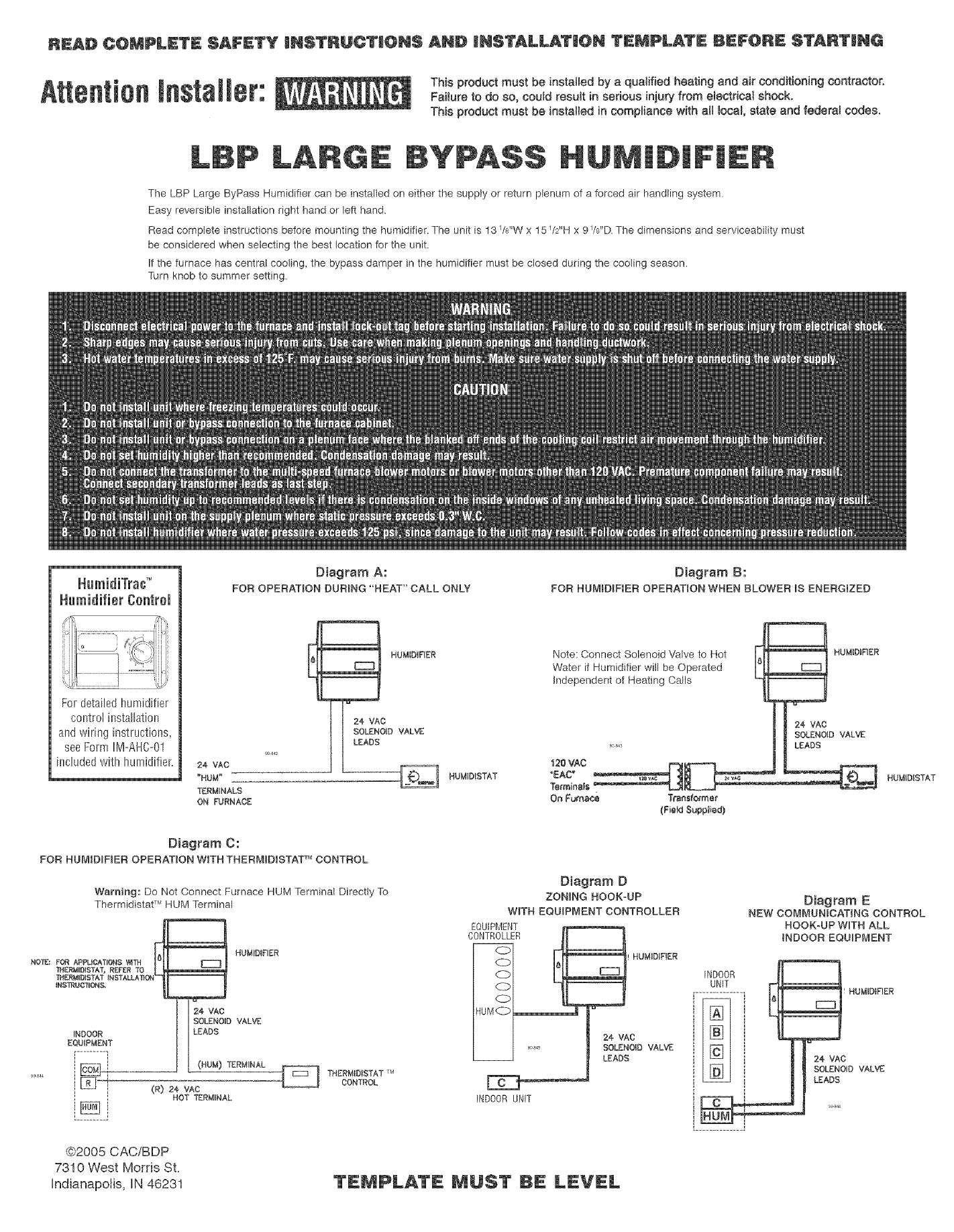
Humidifier Control
Fordetailedhumidifier
controlinstallation
andwiring instructions,
seeFormIIVI-AHC-01
includedwith humidifier. 24 VAC
"HUM"
_RM_NALS
ON FURNACE
Diagram A:
FOR OPERATION DURING "HEAT" CALL ONLY
Diagram C:
TM
FOB HUMID_FBER OPERATION WiTHTHEBM_DiSTAT CONTROL
Warning: Do Not Connect Furnace HUM Terminal Directly To
TM
Thermidistat RUM Terminal
HUMIDIFIER
NO'_E: FOR APPMOATION$ _TH pt| _'-_m
THERM_D!$TAT, REFER TO
_HERMtD_STAT _NSTALLATfON
INSTRUCTIONS,
t]SOLENOID VALVE
_.DOOR i I LEADs
cE_ JL(.umTERM_NA_
LR-EJ_ (R)24 vAc
HOT TERMLNAL
NN
THERMiDISTAT TM
CONTROL
Diagram B:
FOR HUM_D_FiER OPERATION WHEN BLOWER _$ ENERGIZED
HUMIDISTAT
Note: Connect Solenoid Valve to Hot I._1 HUMIDIF_ER
Water if Humidifier will be Operated I-_
independent of Heating Calls i! o
m 24vAc
| I SOLENOIDVALVE
I _ LEADS
Terminals _:
On Furna¢_ Tr_nsfom_er
(Fmld8applied)
HUMID!STAT
Diagram D
ZONING HOOK-UP
WITH EQUIPMENT CONTROLLER
EQUIPMENT
Diagram E
NEW COMMUNICATING CONTROL
HOOK-UP WITH ALL
INDOOR EQUIPMENT
INDOOR UNIT
@2005 CACiBDP
7310 West Morris St.
Indianapolis, IN 46231 TEMPLATE _UST BE LEVEL
TOP
READ COMPLETE SAFETY INSTRUCTIONS AND iNSTALLATiON TEMPLATE BEFORE STARTING
TEMPLATE MUST BE LEVEL
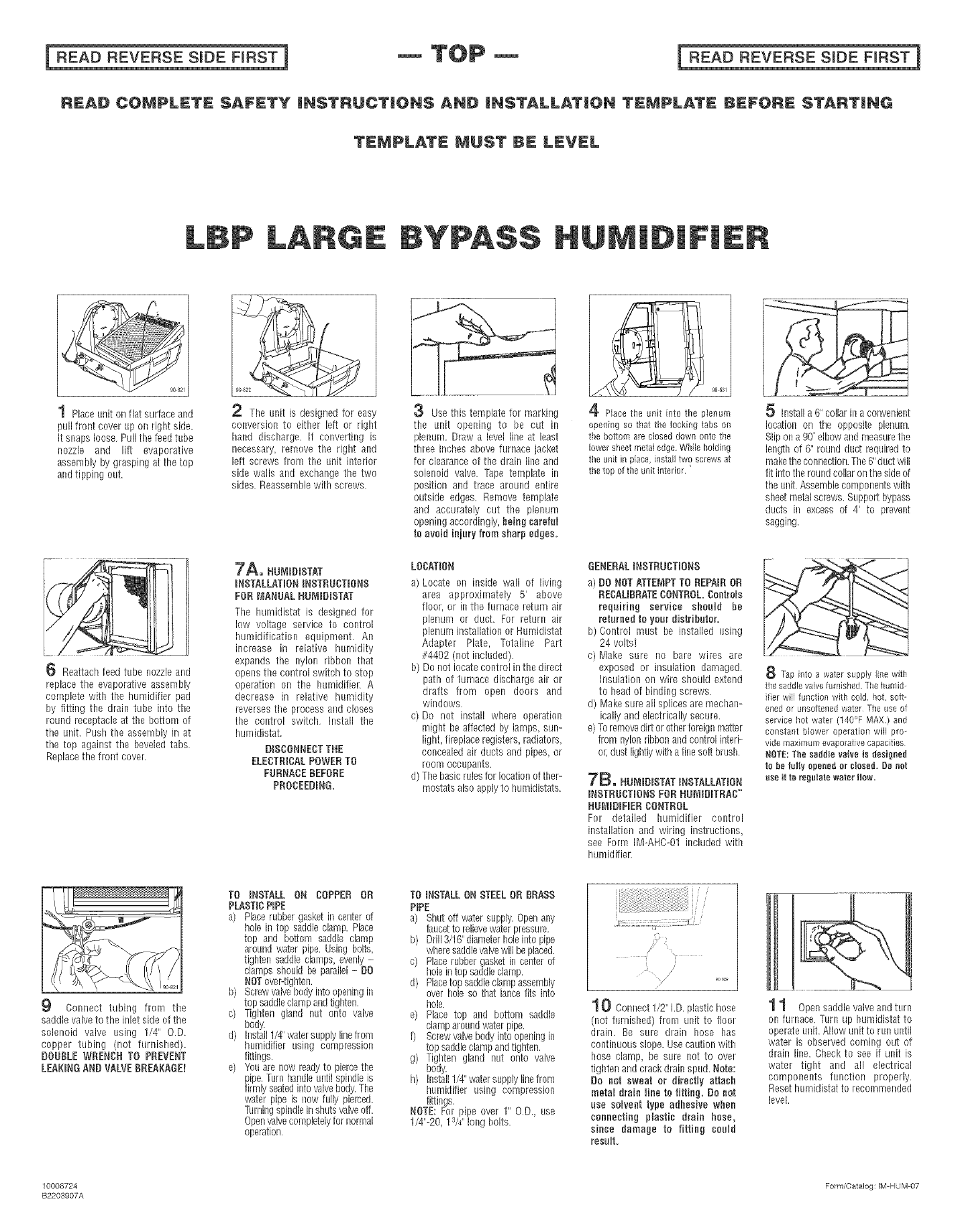
1 Placeunit on flat surface and
pull front cover up on right side.
It snaps loose, Pull the feed tube
nozzle and lift evaporative
assembly by grasping at the top
and tipping out,
6 Reattach feed tube nozzleand
replace the evaporative assembly
complete with the humidifier pad
by fitting the drain tube into the
round receptacle at the bottom of
the unit, Push the assembly in at
the top against the beveled tabs,
Replace the front cover,
9
2 The unit is designed for easy
conversion to either left or right
hand discharge. If converting is
necessary, remove the right and
left screws from the unit interior
side walls and exchange the two
sides, Reassemble with screws,
7A. NUR_D_STAT
_NSTALLAT_ON_NSTBUBT_ONS
FOR MANUAL NUM_D_STAT
The humkBstat is designed for
low voltage service to control
humidification equipment. An
increase in relative humidity
expands the nylon ribbon that
opens the control switch to stop
operation on the humidifier. A
decrease in relative humidity
reverses the process and closes
the control switch, Install the
humidistat.
DISCONNECT THE
ELECTRICAL POWERTO
FURNACE BEFORE
PROCEEDING,
3Use this template for marking
the unit opening to be cut in
plenum. Draw a level line at least
three inches above furnace jacket
for clearance of the drain line and
solenoid valve• Tape template in
position and trace around entire
outside edges• Remove template
and accurately cut the plenum
opening accordingly, beingcareful
to avoid injuryfrom sharp edges.
LOBATION
a) Locate on inside wall of living
area approximately 5' above
floor, or in the furnace return air
plenum or duct. For return air
plenum installation or Humidistat
Adapter Plate, Totaline Part
#4402 (not included)•
b) Do not locate control in the direct
path of furnace discharge air or
drafts from open doors and
windows,
c) Do not install where operation
might be affected by lamps, sun-
light, fireplace registers, radiators,
concealed air ducts and pipes_or
room occupants.
d) The basic rulesfor location of ther-
mostatsalso applyto humidistats.
9B 8,91
4 Placethe unN into the plenum
opening so that the locking tabs on
the bottom arecloseddownonto the
lowersheetmetaledge.Whileholding
the unit in place,instal]two screwsat
thetop ofthe unitinterior.
GENERAL INSTBUGTIONS
a)O0 NOT ATTEMPT TO REPNR OR
REBAUBRATE BONTBOL Controls
requiringservice should he
returnedtoyourdistNbutor_
b) Control must be installed using
24 volts!
c) Make sure no bare wires are
exposed or insulation damaged.
InsulatBm on wire should extend
to head of binding screws,
d) Makesure all splices aremechan-
ically and electrically secure.
e)Toremovedirt or otherforeignmatter
from nylon ribbonand control interi-
or,dust lightly with a fine sob brush.
7B. NU_ImO_STATINSTALLATION
INSTRUCTIONS FOB NUMIDITRAB TM
HUMiDiFiERBONTROL
For detailed hurnidifier control
installation and wiring instructions,
see Form IM-AHC-01 included with
humidifier
Installa 6"collar in a convenient
location on the opposite plenum.
Slip on a go"elbowand measurethe
length of 6" round duct required to
makethe connection•The6"duct will
fit intothe roundcollar on the side of
the unit.Assemblecomponentswith
sheetmetalscrews. Support bypass
ducts in excess of 4' to prevent
sagging.
8 Tap into a water supplyline wth
the saddlevalvefurnished•Thehumid-
ifierwill functionwith cold, hot,soft-
enedor unsoftenedwater Theuseof
servicehot water (140°F MAX) and
constant blower operationwill pro_
vide maximumevaporativecapacities
NOTE:The saddleva{veisdesigned
tobetulIVopenedor dosed. Do net
neeiito _egulatewaterflaw.
Connect tubing from the
saddle valveto the inlet side of the
solenoid valve using 1/4" O.D.
copper tubing (not furnished).
DOUBLE WBENCN TO PREVENT
LEAKINGAND VALVE BREAKAGE!
TO INSTALL ON COPPER OR
PLASTICPIPE
a) Placerubber gasket incenter of
hole in top saddle clamp• Place
top and bottom saddle clamp
around water pipe. Using bolts,
tighten saddle clamps_evenly -
clamps should be parallel- O0
NOTover-tighten.
b) Screwvah!ebody intoopening in
top saddleclamp andtighten.
c) Tighten gland nut onto valve
body•
d) Install1/4"watersupplyline from
humidifier using compression
fittings.
e) Youare now readyto piercethe
pipe.Turn handleuntil spindb is
firmly seatedintovalvebody.The
water pipe is now fully pierced.
Turningspindlein shutsvalveoff.
Openvalvecompletelyfor nonhal
operation,
TO iNSTALLON STEELOR BRASS
PiPE
a) Shut off water supply.Openany
faucetto relievewaterpressure.
b) Drill3/16"diameterholeinto pipe
wheresaddlevalvewill be placed.
c) Place rubbergasket in center of
hole intop saddleclamp.
d) Placetop saddleclampassembly
over hole so that lance fits into
hole.
e) Place top and bottom saddle
clamparound waterpipe.
f) Screwvalvebodyinto openingin
top saddleclampand tighten.
g) Tighten gland nut onto valve
body.
h) Install1/4"watersupply linefrom
humidifier using compression
fittings.
NOTE: For pipe over 1" O,D., use
1/4"-20, 1rW"long bolts,
,/; a,
• • _/"
/
1 0 Connect 1/2"I.D. plastic hose
(not furnished) from unit to floor
drain. Be sure drain hose has
continuous slope, Usecaution with
hose clamp, be sure lint to over
tighten and crack drain spud. Note:
Oo not sweat or directly attach
metal drain line to Btting, Do not
use solvent type adhesive when
connecting plastic drain hose,
sinee damage to fitBng could
resulL
1 1 Opensaddle valve and turn
on furnace. Turn up humidistat to
operate unit, Allow unit to run until
water is observed coming out of
drain line. Check to see if unit is
water tight and all electrical
components function properly.
Reset hnmidistat to recommended
level.
10006724 Form/Catalog: IM-HUM-07
B2203907A
18 This product must be installed by a qualified heating and air conditioning contractor.
Failure to do so, could resutt in serious injury from electrical shock.
"This product must be installed in compliance with all locat, state and federal codes,
The LBP Large ByPass Humidifier can be installed on either the supply or return plenum of a forced air handling system.
Easy reversible installation right hand or left hand.
Read complete instructions before mounting the humidifier. The unit is 13 VB"W x 15 VN'H x 9 VB"D.The dimensions and serviceability must
be considered when selecting the best location for the unit.
If the furnace has central cooling, the bypass damper in the humidifier must be closed during the cooling season.
Turn knob to summer setting.
Humidifier Control
Fordetailedhumidifier
controlinstallation
andwiring instructions,
seeFormIIVI-AHC-01
includedwith humidifier. 24 VAC
"HUM"
_RM_NALS
ON FURNACE
Diagram A:
FOR OPERATION DURING "HEAT" CALL ONLY
Diagram C:
TM
FOB HUMID_FBER OPERATION WiTHTHEBM_DiSTAT CONTROL
Warning: Do Not Connect Furnace HUM Terminal Directly To
TM
Thermidistat RUM Terminal
HUMIDIFIER
NO'_E: FOR APPMOATION$ _TH pt| _'-_m
THERM_D!$TAT, REFER TO
_HERMtD_STAT _NSTALLATfON
INSTRUCTIONS,
t]SOLENOID VALVE
_.DOOR i I LEADs
cE_ JL(.umTERM_NA_
LR-EJ_ (R)24 vAc
HOT TERMLNAL
NN
THERMiDISTAT TM
CONTROL
Diagram B:
FOR HUM_D_FiER OPERATION WHEN BLOWER _$ ENERGIZED
HUMIDISTAT
Note: Connect Solenoid Valve to Hot I._1 HUMIDIF_ER
Water if Humidifier will be Operated I-_
independent of Heating Calls i! o
m 24vAc
| I SOLENOIDVALVE
I _ LEADS
Terminals _:
On Furna¢_ Tr_nsfom_er
(Fmld8applied)
HUMID!STAT
Diagram D
ZONING HOOK-UP
WITH EQUIPMENT CONTROLLER
EQUIPMENT
Diagram E
NEW COMMUNICATING CONTROL
HOOK-UP WITH ALL
INDOOR EQUIPMENT
INDOOR UNIT
@2005 CACiBDP
7310 West Morris St.
Indianapolis, IN 46231 TEMPLATE _UST BE LEVEL

TOP
READ COMPLETE SAFETY INSTRUCTIONS AND iNSTALLATiON TEMPLATE BEFORE STARTING
TEMPLATE MUST BE LEVEL
1 Placeunit on flat surface and
pull front cover up on right side.
It snaps loose, Pull the feed tube
nozzle and lift evaporative
assembly by grasping at the top
and tipping out,
6 Reattach feed tube nozzleand
replace the evaporative assembly
complete with the humidifier pad
by fitting the drain tube into the
round receptacle at the bottom of
the unit, Push the assembly in at
the top against the beveled tabs,
Replace the front cover,
9
2 The unit is designed for easy
conversion to either left or right
hand discharge. If converting is
necessary, remove the right and
left screws from the unit interior
side walls and exchange the two
sides, Reassemble with screws,
7A. NUR_D_STAT
_NSTALLAT_ON_NSTBUBT_ONS
FOR MANUAL NUM_D_STAT
The humkBstat is designed for
low voltage service to control
humidification equipment. An
increase in relative humidity
expands the nylon ribbon that
opens the control switch to stop
operation on the humidifier. A
decrease in relative humidity
reverses the process and closes
the control switch, Install the
humidistat.
DISCONNECT THE
ELECTRICAL POWERTO
FURNACE BEFORE
PROCEEDING,
3Use this template for marking
the unit opening to be cut in
plenum. Draw a level line at least
three inches above furnace jacket
for clearance of the drain line and
solenoid valve• Tape template in
position and trace around entire
outside edges• Remove template
and accurately cut the plenum
opening accordingly, beingcareful
to avoid injuryfrom sharp edges.
LOBATION
a) Locate on inside wall of living
area approximately 5' above
floor, or in the furnace return air
plenum or duct. For return air
plenum installation or Humidistat
Adapter Plate, Totaline Part
#4402 (not included)•
b) Do not locate control in the direct
path of furnace discharge air or
drafts from open doors and
windows,
c) Do not install where operation
might be affected by lamps, sun-
light, fireplace registers, radiators,
concealed air ducts and pipes_or
room occupants.
d) The basic rulesfor location of ther-
mostatsalso applyto humidistats.
9B 8,91
4 Placethe unN into the plenum
opening so that the locking tabs on
the bottom arecloseddownonto the
lowersheetmetaledge.Whileholding
the unit in place,instal]two screwsat
thetop ofthe unitinterior.
GENERAL INSTBUGTIONS
a)O0 NOT ATTEMPT TO REPNR OR
REBAUBRATE BONTBOL Controls
requiringservice should he
returnedtoyourdistNbutor_
b) Control must be installed using
24 volts!
c) Make sure no bare wires are
exposed or insulation damaged.
InsulatBm on wire should extend
to head of binding screws,
d) Makesure all splices aremechan-
ically and electrically secure.
e)Toremovedirt or otherforeignmatter
from nylon ribbonand control interi-
or,dust lightly with a fine sob brush.
7B. NU_ImO_STATINSTALLATION
INSTRUCTIONS FOB NUMIDITRAB TM
HUMiDiFiERBONTROL
For detailed hurnidifier control
installation and wiring instructions,
see Form IM-AHC-01 included with
humidifier
Installa 6"collar in a convenient
location on the opposite plenum.
Slip on a go"elbowand measurethe
length of 6" round duct required to
makethe connection•The6"duct will
fit intothe roundcollar on the side of
the unit.Assemblecomponentswith
sheetmetalscrews. Support bypass
ducts in excess of 4' to prevent
sagging.
8 Tap into a water supplyline wth
the saddlevalvefurnished•Thehumid-
ifierwill functionwith cold, hot,soft-
enedor unsoftenedwater Theuseof
servicehot water (140°F MAX) and
constant blower operationwill pro_
vide maximumevaporativecapacities
NOTE:The saddleva{veisdesigned
tobetulIVopenedor dosed. Do net
neeiito _egulatewaterflaw.
Connect tubing from the
saddle valveto the inlet side of the
solenoid valve using 1/4" O.D.
copper tubing (not furnished).
DOUBLE WBENCN TO PREVENT
LEAKINGAND VALVE BREAKAGE!
TO INSTALL ON COPPER OR
PLASTICPIPE
a) Placerubber gasket incenter of
hole in top saddle clamp• Place
top and bottom saddle clamp
around water pipe. Using bolts,
tighten saddle clamps_evenly -
clamps should be parallel- O0
NOTover-tighten.
b) Screwvah!ebody intoopening in
top saddleclamp andtighten.
c) Tighten gland nut onto valve
body•
d) Install1/4"watersupplyline from
humidifier using compression
fittings.
e) Youare now readyto piercethe
pipe.Turn handleuntil spindb is
firmly seatedintovalvebody.The
water pipe is now fully pierced.
Turningspindlein shutsvalveoff.
Openvalvecompletelyfor nonhal
operation,
TO iNSTALLON STEELOR BRASS
PiPE
a) Shut off water supply.Openany
faucetto relievewaterpressure.
b) Drill3/16"diameterholeinto pipe
wheresaddlevalvewill be placed.
c) Place rubbergasket in center of
hole intop saddleclamp.
d) Placetop saddleclampassembly
over hole so that lance fits into
hole.
e) Place top and bottom saddle
clamparound waterpipe.
f) Screwvalvebodyinto openingin
top saddleclampand tighten.
g) Tighten gland nut onto valve
body.
h) Install1/4"watersupply linefrom
humidifier using compression
fittings.
NOTE: For pipe over 1" O,D., use
1/4"-20, 1rW"long bolts,
,/; a,
• • _/"
/
1 0 Connect 1/2"I.D. plastic hose
(not furnished) from unit to floor
drain. Be sure drain hose has
continuous slope, Usecaution with
hose clamp, be sure lint to over
tighten and crack drain spud. Note:
Oo not sweat or directly attach
metal drain line to Btting, Do not
use solvent type adhesive when
connecting plastic drain hose,
sinee damage to fitBng could
resulL
1 1 Opensaddle valve and turn
on furnace. Turn up humidistat to
operate unit, Allow unit to run until
water is observed coming out of
drain line. Check to see if unit is
water tight and all electrical
components function properly.
Reset hnmidistat to recommended
level.
10006724 Form/Catalog: IM-HUM-07
B2203907A
