CARRIER Package Units(both Units Combined) Manual L0521271
User Manual: CARRIER CARRIER Package Units(both units combined) Manual CARRIER Package Units(both units combined) Owner's Manual, CARRIER Package Units(both units combined) installation guides
Open the PDF directly: View PDF ![]() .
.
Page Count: 64
48PG20-28
Single Package Rooftop Units
Electric Cooling/Gas Heating with
Electromechanical Controls and PURON® (R-410A) Refrigerant
Installation,
CONTENTS
Page
SAFETY CONSIDERATIONS .......................... 1,2
INSTALLATION ...................................... 2-17
Step 1 -- Provide Unit Support ......................... 2
• ROOF CURB
• ALTERNATE UNIT SUPPORT
• SLAB MOUNT
Step 2 -- Remove Shipping Rails ....................... 2
Step 3 -- Rig and Place Unit ............................ 2
• POSITIONING
• ROOF MOUNT
• INSTALLATION ONTO CURB
Step 4 -- Field Fabricate Ductwork ..................... 9
Step 5 -- Make Unit Duct Connections .................. 9
• VERTICAL CONFIGURATION
• HORIZONTAL APPLICATIONS
Step 6 -- Install Flue Hood and Inlet Hood ............ 10
Step 7 -- Trap Condensate Drain ..................... 10
Step 8 -- Install Gas Piping ........................... l0
Step 9 -- Make Electrical Connections ................. I I
• FIELD POWER SUPPLY
• FIELD CONTROL WIRING
Step 10 -- Install Outdoor-Air Hood ................... 12
• MANUAL DAMPER ASSEMBLY
Step 11 -- Position Optional Power
Exhaust or Barometric Relief Damper Hood ......... 16
Step 12 -- Non-Fused Disconnect .................... 16
Step 13 -- Install All Accessories ..................... 16
PRE-START-UP ....................................... 18
START-UP ........................................... 18-45
Unit Preparation ...................................... 18
Compressor Mounting ................................ 18
Refrigerant Service Ports ............................. 18
Crankcase Heater(s) .................................. 18
Compressor Rotation ................................. 18
Internal Wiring ........................................ 18
Subcooler Heat Exchanger (SHX) ..................... 18
Evaporator Fan ....................................... 18
Condenser Fans and Motors .......................... 19
Return-Air Filters ..................................... 19
Outdoor-Air Inlet Screens ............................. 19
Gas Heat .............................................. 19
Optional EconoMi$er IV ............................... 39
Operating Sequence .................................. 44
SERVICE ............................................ 4(,-57
Cleaning .............................................. 46
Lubrication ........................................... 4"7
Manual Outdoor Air Damper .......................... 48
Economizer Adjustment .............................. 48
Evaporator Fan Service and Replacement ............ 48
Evaporator Fan Performance Adjustment ............. 48
Evaporator Fan Belt Tension Adjustment ............. 48
Condenser Fan Adjustment ........................... 49
Verify Sensor Performance ........................... 49
Economizer Operation During Power Failure .......... 49
Evacuation ........................................... 49
Refrigerant Charge ................................... 50
Gas Valve Adjustment ................................ 50
High Altitude .......................................... 51
Main Burners ......................................... 51
Filter Drier ............................................ 52
Protective Devices .................................... 52
Relief Devices ........................................ 52
Start-Up and Service Instructions
Page
Control Circuit, 24-V .................................. 52
Replacement Parts .................................... 52
Diagnostic LEDs ...................................... 52
TROUBLESHOOTING .............................. 57-61
Unit Troubleshooting .................................. 57
EconoMi$er IV Troubleshooting ....................... 60
Phase Loss Protection ................................ 61
UNIT START-UP CHECKLIST ........................ CL-I
SAFETY CONSIDERATIONS
Installation and servicing of air-conditioning equipment can
be hazardous due to system pressure and electrical compo-
nents. Only trained and qualified service personnel should
install, repair, or service ai>conditioning equipment.
Untrained personnel can perform the basic maintenance
functions of cleaning coils and filters and replacing filters. All
other operations should be perforlned by trained service per-
sonnel. When working on air-conditioning equipment, observe
precautions in the literature, tags and labels attached to the unit,
and other safety precautions that may apply.
Follow all safety codes. Wear safety glasses and work
gloves. Use quenching cloth for unbrazing operations. Have
fire extinguishers available for all brazing operations.
Before performing service or maintenance operations on
unit, turn off main power switch to unit. Electrical shock
could cause personal injury.
Puron (R-410A) refrigerant systems operate at higher pres-
sures than stan&trd R-22 systems. Do not use R-22 service
equipment or components on Puron refrigerant equipment.
If service equipment is not rated for Puron tefiigemnt,
equipment dmnage or personal injury may result.
1. [mproper installation, adjustment, alteration, service,
or maintenance can cause property &tmage, personal
injury, or loss of life. Refer to the User's Information
Manual provided with this unit for mote details.
2. Do not store or use gasoline or other flammable
vapors and liquids in the vicinity of this or any other
appliance.
What to do if you smell gas:
1. DO NOT try to light any appliance.
2. DO NOT touch any electrical switch, or use any
phone in your building.
3. IMMEDIATELY call your gas supplier from a neigh-
bor's phone. Follow the gas supplier's instructions.
4. If you cannot reach your gas supplier, c_dl the fire
department.
Manufacturer reserves the right to discontinue, or change at any time, specifications or designs without notice and without incurring obligations.
PC 111 Catalog No. 534-80211 Printed in U,S.A. Form 48PG-10SI Pg 1 9-05 Replaces: New
Disconnect gas piping from unit when pressure testing at
pressure greater than 0.5 psig. Pressures greater than
0.5 psig will cause gas valve dmnage resulting in hazardous
condition. If gas valve is subjected to pressure greater than
0.5 psig, it must be replaced before use. When pressure
testing lield-supplied gas piping at pressures of 0.5 psig or
less, a unit connected to such piping must be isolated by
closing the manual gas valve(s).
IMPORTANT: Units have high ambient operating limits. If ]
limits are exceeded, the units will automatically lock the I
compressor out of operation. Manual reset will be required
to restart the compresso]:
INSTALLATION
Step 1 -- Provide Unit Support
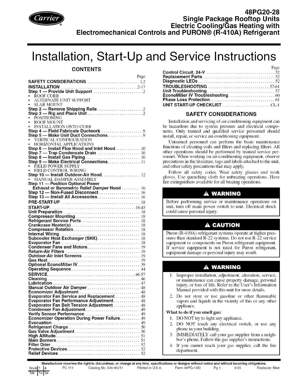
ROOF CURB -- Assemble or install accessory roof curb in
accor&mce with instructions shipped with this accessory. See
Fig. 1. Install insulation, cant strips, roofing, and counter flash-
ing as shown. DuctwoN can be installed to roof curb before
unit is set in place. Ductwork must be attached to curb and not
to the unit. Curb must be level. This is necessary to permit unit
drain to function properly. Unit leveling tolerance is _+1/1(_in.
per line,u ft in any direction. Refer to Accessory Roof Curb [n-
st_dlation Instructions for additional information as required.
When accesso qroof curb is used, unit may be installed on
class A, B, or C roof covering material. Carrier roof curb acces-
sories are for flat roofs or slab mounting.
IMPORTANT: The gasketing of the unit to the roof curb is
critical for a watertight seal. Install gasket with the roof
curb as shown in Fig. 1. hnproperly applied gasket cml also
result in air leaks and poor unit performance. Do not slide
unit to position on roof curb.
ALTERNATE UNIT SUPPORT- When a curb cannot be
used, install unit on a noncombustible surface. Support unit
with sleepe].s, using unit curb support area. If sleepers cannot
be used, support long sides of unit with a minimum of 3 equal-
ly spaced 4-in. x 4-in. pads on each side.
SLAB MOUNT (Horizontal Units Only) -- Provide a level
concrete slab that extends a minimum of 6 in. beyond unit cab-
inet. Install a gravel apron in front of condenser coil zdr inlet to
prevent grass and foliage from obstructing airflow.
NOTE: Horizontal units may be installed on a roof curb if
required.
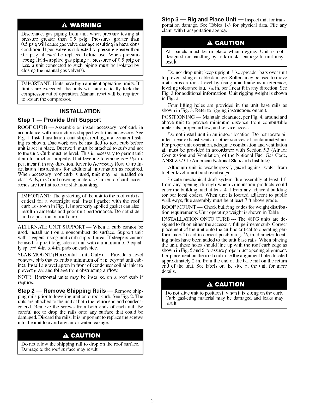
Step 2 -- Remove Shipping Rails -- Remove ship-
ping rails prior to lowering unit onto roof curb. See Fig. 2. The
rails are attached to the unit at both the return end and condens-
er end. Remove the screws from both ends of each rail. Be
cmeful not to drop the rails onto gray surface that could be
dmnaged. Disc¢ud the rails. It is important to replace the screws
into the unit to avoid any air or water leakage.
Step 3 -- Rig and Place Unit -- Inspect unit for trans-
portation &_mage. See Tables 1-3 for physical data. File any
chfim with transportation agency.
All panels must be in place when rigging. Unit is not
designed for handling by fork truck. Dmnage to unit may
result.
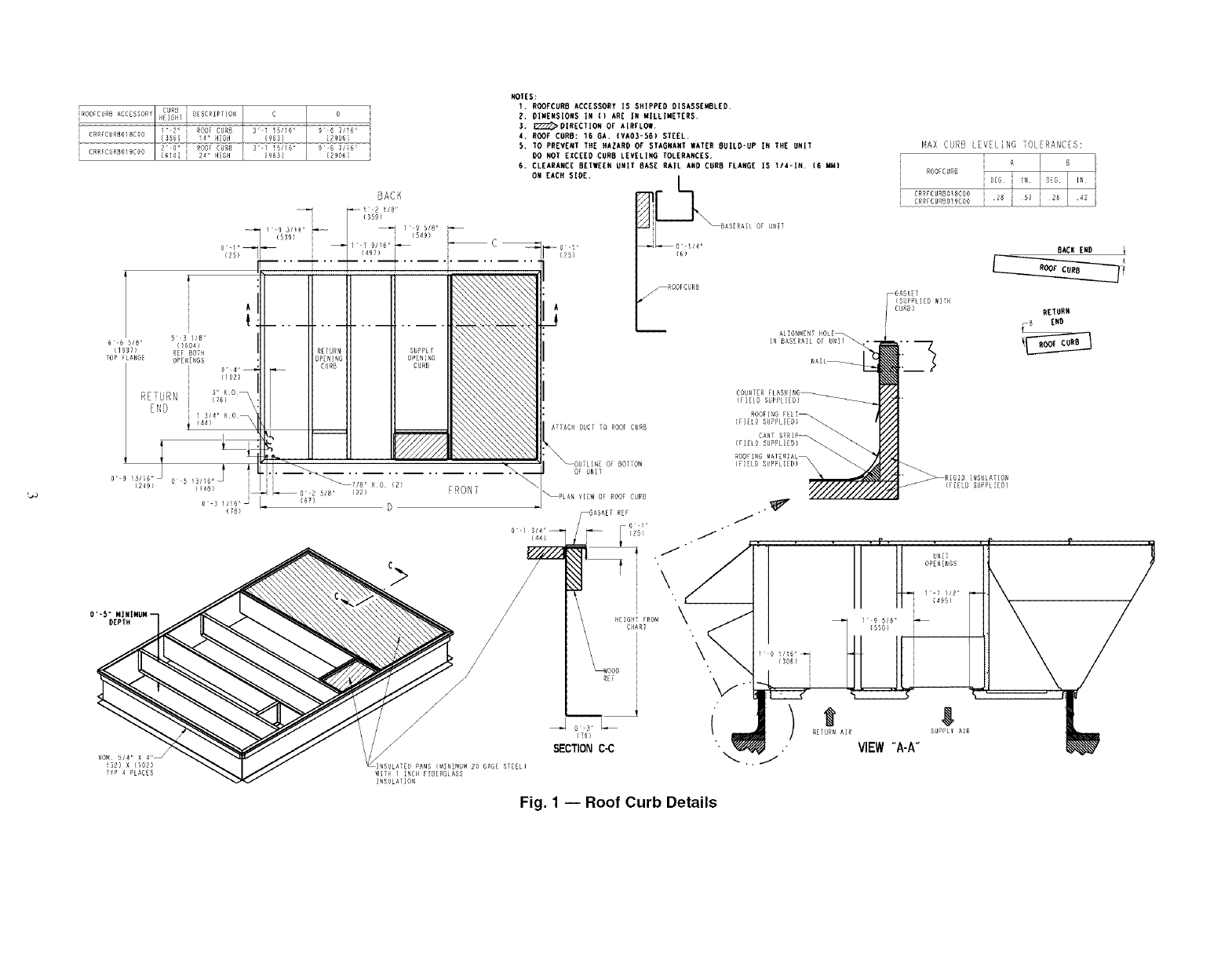
Do not diop unit; keep upright. Use spreader ba].s over unit
to prevent sling or cable damage. Rollers may be used to move
unit across a roof. Level by using unit frmne as a reference;
leveling tolerance is _+1/1_in. per line,u" ft in troy direction. See
Fig. 3 for additional information. Unit rigging weight is shown
in Fig. 3.
Four lifting holes m'e provided in the unit base mils as
shown in Fig. 3. Refer to rigging instructions on unit.
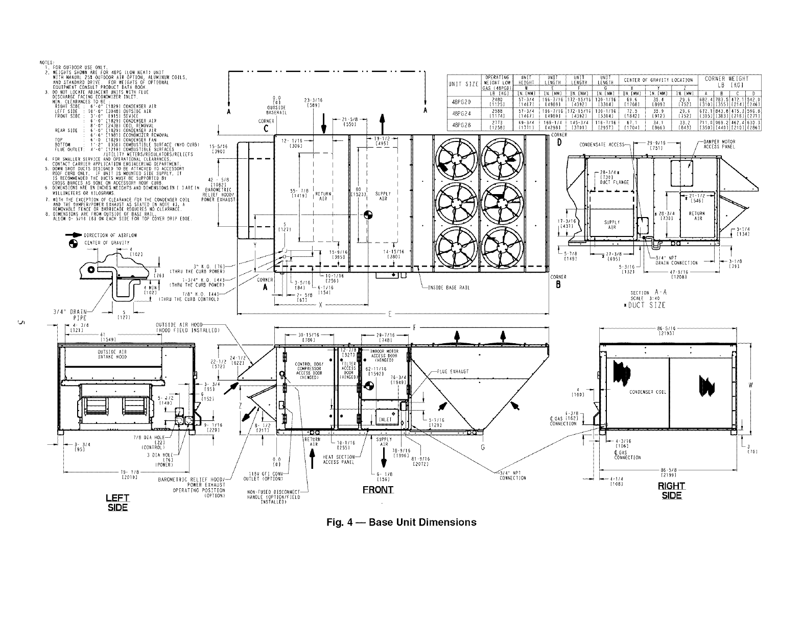
POSITIONING -- Maintain clearance, per Fig. 4, around and
above unit to provide minimum distance from combustible
materials, proper _firflow, and service access.
Do not inst_fll unit in an indoor location. Do not locate air
inlets near exhaust vents or other sources of contaminated ai]:
For proper unit operation, adequate combustion and ventilation
air must be provided in accordance with Section 5.3 (Air for
Combustion and Ventilation) of the Natiomd Fuel Gas Code,
ANSI Z223.1 (American National Standmds Institute).
Although unit is weatherproof, guard against water from
higher level runoff and overhangs.
Ix>cate mechanical di'aft system flue assembly at least 4 ft
from any opening through which combustion products could
enter the building, and at least 4 ft flom any adjacent building
(or per local codes). When unit is located adjacent to public
w_dkways, flue assembly must be at least 7 ft above grade.
ROOF MOUNT -- Check building codes for weight distribu-
tion requirements. Unit operating weight is shown in Table 1.
INSTALLATION ONTO CURB -- The 48PG units m'e de-
signed to lit on either the accessory full perimeter curb. Correct
placement of the unit onto the curb is critical to operating per-
formance. To aid in correct positioning, 3/s-in. diameter locat-
ing holes have been added to the unit base rails. When placing
the unit, these holes should line up with the roof curb edge as
shown in Fig. 5 and 6, to assure proper duct opening alignment.
For placement on the roof curb, use the alignment holes located
approximately 2-in. from the end of the base rail on the return
end of the unit. See labels on the side of the unit for more
details.
Do not slide unit to position it when it is sitting on the curb.
Curb gasketing material may be &tmaged and leaks may
result.
Do not allow the shipping rail to drop on the ]'(>ofsurface.
Dmnage to the ]'(>ofsurface may result.
iROOFSS_SAS_E_ORY_T _S_,E_T_ONS S
i CRRFCUR_OIBCeO 9B_/iB_
_290_)
CRRECYRBOlgC_O iSgDBi
FRONT
NOT[S:
I, ROOFCUR8 ACCESSORY IS SH|PP[O OISASS[MBL[D.
?. OI#ENSION$ IN 1) ARE IN UlLLIMET[R$.
3. _OIRECTION OF AIRFLOW.
4. ROOF CURS: 16 6A. {VA03-56) ST[EL
5, TO PREV[NT THE HAZARD OF STAGNANT WAT[R 8UILO*UP IN TH[ UNIT
DO NOT £XC[[D CUR8 L[VELING TOL[RANCES.
6. CLEARANC[ fi[TWE[I_ UNIT 8AS[ RAIL AND CURB FLAN6[ IS t/4-1N. (6 MM)
ON [ACH SIOE, __SAS RAIL OF UN !
-ROOFC RB
ALIGNMENT SOLE\
IN BASSRAIL OF U_IT
MAX CURB L VEL]NG TOLERANC S:
ROOCBRS SG , :::;G IN ::
CRRFCURgOISC_O
ERRFCURgO 9C00 28
BACK [NO
_GASKE[
i (S_PPLIEB WITS
CUR_) R£_RN
_ _ND
COUNTER FLASHING
ROOFING FELi_
{FILL9 SBPPL_Eg)
CANT STRIP_
(FIELS SUPPLIEO)
_RIGIO INSULATION
(FIELD SUPPL_EO)
9 S/6 '=
(5S0)
y,
VIEW"A-A"
IN[
OPSN NGS
,B
SUPPLY AiR
Fig. 1 -- Roof Curb Details
SHIPPING
Fig. 2 -- Shipping Rail Removal
CAUTION NOTICE TO RIGGERS:
ALL PANELS MUST BE IN PLACE WHENRIGGING.
NOTICE TO RIGGERS: Rig by inserting hooks into unit base rails as shown. Maintain a distance of
120 inches (3048 MM) from top of unit to eyehook. Leave coil cover attached to unit whilerigging to
protect coil of unit from damage.
J
J
PG28 4300 70.5 37.0 35.2 .%
DOES NOT INCLUDE ERV ( ENERGY RECOVERY VENTILATOF OPTION. /j_
/ / x/ o o i
_ OT !$1250ii_( r68niktgi)fOartidO?moeStriC_ra_irt_g" _'_'_
Fig. 3 -- Rigging Details
ROTES:
l FOR OUTDOOR USE ONLY
? WEIGHTS SHOWN ARE FOR 48PG CLOW REA[I UNIT
WiTH MANUAL ?5% OUTDOOR AIR OPTION, ALUMIND_ COILS,
AND STANDARD DRIVE FOR WEIGHTS OF OPTIONAL
EQUIPMENT CONSULT PRODUCT DATA BOOK
3 DO NOT LOCATE ADJACENT UNITS WITH FLUE
DISCHARGE FACING ECONOMIZER INLET¸
NIN CLEARANCES TO _E
RIGHT SIDE ; 6'0 = [1829] CONDENSER AIR
LEFf SIDE : 10'0" I304D] OUTSIDE AIR
FRONT SIDE ; 3'0 .[915] SEVICE
• 6' D" 11829] CONDENSER AIR
• 8' D" 12438] COIL RE_OVAL
REAR SIDE : 6' D" liB?9] CONDENSER AIR
• 6'6 .i_981] ECONOMIZER REMOVAL
iUNIT SIZE
48PG20
48PG24
48PG28
OPERATING i
_EIGRT LOWl
GAS (4SPUD]
LR [KGIi
2480
[11P51
3588
[I_74]
2173
[125C1
UNIT I UNIT I UNIT UNIT I
FiE HT LENGTH LENGTH LENGTH CENPER OF GRAVITY LOCATION CORNER WEIGHT
E F G X Y Z LB [KG]
57_3/4 13DI/1U _! 696 [ 354 296 6824 7855 4721 5420
H467] [33D4] } 11768] I [8991 [7521 {31D] [3551 {214] 124U]
57-3/4 i196_1/16 i172-[5/1_ 130-1/161 725 i 359 396 6721 843 8 4?5 _ 596 8
H4611 i [49891 i [4392] [3304] t1842] i [9_2] [752] [305] [383] [216] [271]
69_3/4 i 159-1/4 i ]45-3/4 HU-?/1U i U71 i 341 33? 7110 9UD D 4U_ UND 3
11771} I [42981 i [3701] [2957] i 11704] i [8661 [8451 [3SO] [4401 121D] 1_86]
CONNER
5
6
7
8
TOP 6'0 11829] CONDENSER FAN
80TTO_ : I'D .[356] CO_BUSTIULE S_RFACE {WlO C_RU) IS 511 U
FLUE OUTLET: _' O" 11219] COMBUSTIBLE SURFACES
/UTILITY METERS/REGULATORS/RZLI_ES _390]
_OR S_ALLER SERVICE AND OPERATIONAL CLEARANCES, I_
CONTACT CARRIER APPLICATION ENGINEERING OEPART_ENT T
DOWN S_OT OUCTS DESIGNED TO BE ATTACHED TO ACCESSORY
ROOF CUR_ ONLY¸ IF UNIT IS MOUNTED SIDE S_PPLY, El
IS RECOMMENDED THE U_CIS MUST DE SUPPORIEU DY 41 - 5/8
CROSS CRACES AS DONE ON ACCESSORY RO0_ CUR_ _IOG?]
DIMENSIONS A E IN I CHES _E[G_TS AND OIMENSIONSIN [ ]ARE i_ ARM _R
T R A D 0 E IC
ILLI_E ERS 0 KILOGR MS RELIEF HOOD/
_JTH THE EXCEPTION OF CLEARANCE FOR IHE CONDENSER COIL POWER EXHAUST
AND THE UAMPER/PO_ER EXHAUST AS S_ATEU IN NO_E _3, A ]
REMOVABLE FENCE OR BARRICADE REQUIRES NO CLEARANCE L
DIZENS]ORS ARE FROM OUTSIDE OF BASE RAIL¸
ALLO_ _- 5116 [8] O_ EACH SIDE FOR TOP COVER DRIP EDGE¸
'_DImDIRECTiON OF AIRFLOW
_ CENTER OF GRAV]IY 4
[lOUl
_ S" KO [?_l J
S (T_RU THE CURB POWER}
I?61 J
i-S/4" KO [441
4 MI_ {THRU T_E CURB POWER)
J
1102] 7/8" KO 144] j
{THRU THE CURB CONTROL}
/
3/4 =` DRA[ 5 L._
PIPE H21[
Do P3 3/16
IO1 1589]
OUTSIDE
_ASERA[L
l' I
I
ss- 7Is I I
-- I I
!_1 / I I
LI, _ _½
Y
[595]
'r [
, -WL:o:
L3511 _ [25
1841 gl 61/1_
_2- 5/8 [1541
[67i X
60
D523L SLAPIPLY
4"15/16
[38D]
L___U
@
_INSICE BASE RAIL
mm
MOTOR
CONDERSATE ACCESS_ [751} ACCESS PANEL
[]
783/4 RETURN
[1301 AIR
l
_---2D- 3/4 ;_
I?3o] I_
I DUCT FLANGE
--5"i/4
[1341
[$49] NPT
DRAIN CONNECTION
liB?} 9/1D_
CORNER [1208]
BSECPIONAA
SCALE 3:40
*DUCT SIZE
3-118
[79]
t_ _ P" 4314 OUTSIDE AIR HOOO_ [
i 121 [HOOD E ELD NGTALLEG " " i_]_
:- - z• : ..... - - , .................. . , -
72_IIU :627 CONTROL_OX/ e_ILIER " 'H:NG[U)
It t &IJ ........"II....l:;,. us /II
[572} COMPR S OR ACCESS 62- 6 E: --XHA T
I _ ....., , , , , , d" l.J 3- 3141 r, , I _l [HINGED} IIiHING[D_ ,11976"_/41191 _ ..... * !• I I_IF_VI
r.--_ . .. P __-L,.,I , [,D._,_\/,,;DISH.°.s.co.
|-- J L---_!T'.'?_. 'iN_]_/1;.': I,!'i I ,ii _, _......_.!]_ ;.: ._./ :O.E{.O,_"l_t
U _ /U L/ _'" _. _ _-ua ._.... _._...... 'oa'-'_ __1-1
_S- 3 4 , _ , / _ ! AIR ". AIR I i {06_
_,,5, 'oo"'"_']/I /I/!. _?u.,. .,D,,,6"]_ G _ ' q _oAs' -o,
3 DIA _Oi[ I _ HEAT SECT ON_ [199U] R 9/16 ]CON_ECTION
O O AC _AN : i
,/ io,, !fcEss,E. €.o,,, !
i 79- 1/8 _ HUV Gr _ CONV_ 6 W8 V_/_ I_T _" 86518
[2OIO] BAROMETRIC RELIEF HOOCI _ OUTLET {O;T]ON) 1 [1561 CONNECTION _4q/4 [2199]
POWEREXHAUSt i_oB] RIGHT
OPERATING POSITION NON FUSED DISCONNECT _ F_
LEFT (OPTION1 HANDLE IOPTION/FIZLD I_
I_SIALLZD)
Fig. 4 -- Base Unit Dimensions
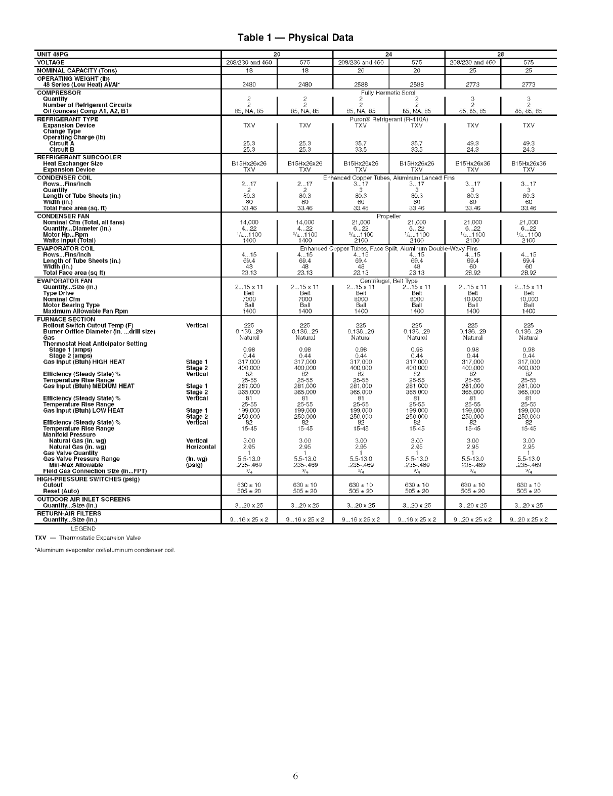
Table 1 -- Physical Data
UNIT 48PG 20 24 28
VOLTAGE 208/230 and 460 575 208/230 and 460 575 208/230 and 460 575
NOMINAL CAPACITY (Tons) 18 18 20 20 25 25
OPERATING WEIGHT (Ib)
48 Series (Low Heat) AI/AI* 2480 2480 2588 2588 2773 2773
COMPRESSOR Fully Hermetic Scroll
ouan,,, i i i
Number of Refrigerant Circuits 22 2222
OII (ounces) Comp A1, A2, B1 85, NA, 85 85, NA, 85 85, NA, 85 85, NA, 85 85, 85, 85 85, 85, 85
REFRIGERANT TYPE Puror'_ Refrigerant (R-410A)
Expansion Device TXV TXV TXV TXV TXV TXV
Change Type
Operating Charge (Ib)
Circuit A 25.3 25.3 35.7 35.7 49.3 49.3
Circuit B 25.3 25.3 33.5 33.5 24.3 24.3
REFRIGERANT SUBCOOLER
Heat Exchanger Size B15Hx26x26 B15Hx26x26 B15Hx26x26 B15Hx26x26 B15Hx26x36 B15Hx26x36
Expansion Device TXV TXV TXV TXV TXV TXV
CONDENSER COIL Enhanced Copper Tubes, Aluminum Lanced Fins
Rows...Flns/Inch 2...17 2...17 3...17 3...17 3...17 3...17
Quantity 22 3333
Length of Tube Sheets (in.) 80.3 80.3 80.3 80.3 80.3 80.3
Width (in.) 60 60 60 60 60 60
Total Face area (sq. it) 33.46 33.46 33.46 33.46 33.46 33.46
CONDENSER FAN Propeller
.om,na,Om,,o,a,.,,an., .0001 1000 10001 1000 ,000
Quantgy...Dlameter (in.) 4...22 4...22 6...22 6...22 6...22 6...22
Motor Hp...Rpm 1/4...1100 1/4...1100 1/4...1100 V4...1100 V4...1100 V4...1100
Waits Input (Total) 1400 1400 2100 2100 2100 2100
EVAPORATOR COIL Enhanced Copper Tubes, Face Split, Aluminum Double-Wavy Fins
Rows...Flns/Inch 4...15 4...15 I 4...15 4...15 I 4...15 4...15
Length of Tube Sheets (In.) 69.4 69.4 I 69.4 69.4 I 69.4 69.4
Width (In.) 48 48 48 48 60 60
Total Face area (sq it) 23.13 23.13 23.13 23.13 28.92 28.92
EVAPORATOR FAN Centrifugal, Belt Type
Quantgy...SIze (in.) 2...15 x 11 2...15 x 11 2...15 x 11 2...15 x 11 2...15 x 11 2...15 x 11
Belt Belt Belt Belt Belt Belt
7000 7000 8000 8000 10,000 10,000
Ball Ball Ball Ball Ball Ball
1400 1400 1400 1400 1400 1400
Vertical
Type Drive
Nominal Cfm
Motor Bearing Type
Maximum Allowable Fan Rpm
FURNACE SECTION
Rollout Switch Cutout Temp (F)
Burner Orifice Diameter (in....drill size)
Gas
Thermostat Heat Anticipator Setting
Stage 1 (amps)
Stage 2 (amps)
Gas Input (Btuh) HIGH HEAT Stage 1
Stage 2
VerUcal
Efficiency (Steady State) %
Temperature Rise Range
Gas Input (Btuh) MEDIUM HEAT Stage 1
Stage 2
Efficiency (Steady State) %Vertical
Temperature Rise Range
Gas Input (Btuh) LOW HEAT Stage 1
Stage 2
Efficiency (Steady State) %Vertical
Temperature Rise Range
Manifold Pressure
Natural Gas (in. wg) VerUcal
Natural Gas (in. wg) Horizontal
Gas Valve Quantity
Gas Valve Pressure Range (in. wg)
MIn-Max Allowable (pslg)
Field Gas Connection Size (In...FPT)
HIGH-PRESSURE SWITCHES (pelg)
Cutout
Reset (Auto)
OUTDOOR AIR INLET SCREENS
Ouantlty...Slze (in.)
RETURN-AIR FILTERS
Quantgy...Slze {In.)
LEGEND
TXV -- Thermostatic Expansion Valve
225
0.13629
Natural
0.98
0.44
317,000
400,000
82
25-55
281,000
365,000
81
25-55
199,000
250,000
82
15-45
3.00
2.95
1
5.5-13.0
.235-.469
3/4
225
0.13629
Natu_l
0.98
0.44
317,000
400,000
82
25-55
281,000
365,000
81
25-55
199,000
250,000
82
15-45
3.00
2.95
1
5.5-13.0
.235-.469
3/4
225
0.13629
Natural
0.98
0.44
317,000
400,000
82
25-55
281,000
365,000
81
25-55
199,000
250,000
82
15-45
3.00
2.95
1
5.5-13.0
.235-.469
¾
225
0.13629
Natu_l
0.98
0.44
317,000
400,000
82
25-55
281,000
365,000
81
25-55
199,000
250,000
82
15-45
3.00
2.95
1
5.5-13.0
.235-.469
¾
225
0.13629
Natural
0.98
0.44
317,000
400,000
82
25-55
281,000
365,000
81
25-55
199,000
250,000
82
15-45
3.00
2.95
1
5.5-13.0
.235-.469
¾
225
0.13629
Natural
*Aluminum evaporator coil/aluminum condenser coil.
0.98
0.44
317,000
400,000
82
25-55
281,000
365,000
81
25-55
199,000
250,000
82
15-45
3.00
2.95
1
5.5-13.0
.235-.469
3/4
630 ± 10 630 ± 10 630 ± 10 630 ± 10 630 ± 10 630 ± 10
505 ± 20 505 ± 20 505 ± 20 505 ± 20 505 ± 20 505 ± 20
3...20 x 25 3...20 x 25 3...20 x 25 3...20 x 25 3...20 x 25 3...20 x 25
9...16 x 25 x 2 9...16 x 25 x 2 9...16 x 25 x 2 9...16 x 25 x 2 9...20 x 25 x 2 9...20 x 25 x 2
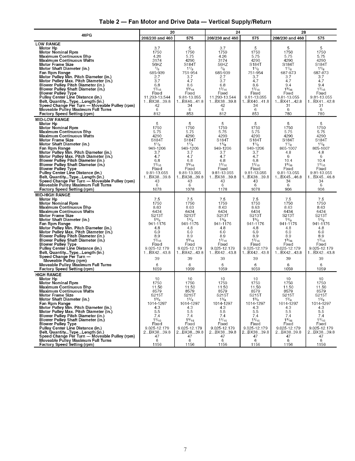
Table 2 -- Fan Motor and Drive Data -- Vertical Supply/Return
48PG
LOW RANGE
Motor Hp
Motor Nominal Rpm
Maximum Continuous Bhp
Maximum Continuous Watts
Motor Frame Size
Motor Shaft Diameter (in.)
Fan Rpm Range
Motor Pulley Min, Pitch Diameter (in.)
Motor Pulley Max, Pitch Diameter (in,)
Blower Pulley Pitch Diameter (in.)
Blower Pulley Shaft Diameter (in.)
Blower Pulley Type
20
208/230 and 460 575
3.7
1750
4.26
3174
56HZ
7&
685-939
2.7
3.7
6.8
13/16
Fixed
5
1750
5.75
4290
$184T
11&
751-954
3,7
4,7
8,6
13/16
Fixed
24
208/230 and 460
3.7
1750
4.26
3174
56HZ
7/s
685-939
2.7
3.7
6.8
13/16
Fixed
575
5
1750
5.75
4290
S184T
l_&
751-954
3.7
4.7
8.6
13/16
Fixed
28
208/230 and 460
5
1750
5.75
4290
$184T
1%
687-873
3.7
4.7
9.4
13/16
Fixed
Pulley Center Line Distance (in.)
Belt, Quantity...Type...Length (in.)
Speed Change Per Turn -- Moveable Pulley (rpm)
Moveable Pulley Maximum Full Turns
Factory Speed Setting (rpm)
MID-LOW RANGE
Motor Hp
Motor Nominal Rpm
Maximum Continuous Bhp
Maximum Continuous Watts
Motor Frame Size
Motor Shaft Diameter (in.)
Fan Rpm Range
Motor Pulley Min. Pitch Diameter (in.)
Motor Pulley Max. Pitch Diameter (in.)
Blower Pulley Pitch Diameter (in.)
Blower Pulley Shaft Diameter (in.)
Blower Pulley Type
Pulley Center Line Distance (in.)
Belt, Quantity...Type...Length (in.)
11.293-13.544
1...BX38...39.8
42
6
812
5
1750
5.75
4290
S184T
11&
949-1206
3.7
4.7
6.8
13/16
Fixed
9.81-13.055
1...BX38...39.8
9,81-13,055
1 -.BX40-,41.8
34
6
853
5
1750
5.75
4290
$184T
1%
949-1206
3.7
4.7
6.8
13/16
Fixed
9.81-13.055
1...BX38_.39.8
11.293-13.544
1-.BX38...39.8
42
6
812
5
1750
5.75
4290
$184T
1%
949-1206
3.7
4.7
6.8
13/16
Fixed
9.81-13.055
1_.BX38._39.8
9.81-13.055
1._BX40...41.8
34
6
853
5
1750
5.75
4290
S184T
l_&
949-1206
3.7
4.7
6.8
13/16
Fixed
9.81-13.055
1...BX38...39.8
9.81-13.055
1_.BX41 _.42.8
31
6
780
Speed Change Per Turn -- Moveable Pulley (rpm)
Moveable Pulley Maximum Full Turns
Factory Speed Setting (rpm)
MID-HIGH RANGE
Motor Hp
Motor Nominal Rpm
Maximum Continuous Bhp
Maximum Continuous Watts
Motor Frame Size
Motor Shaft Diameter (in.)
Fan Rpm Range
Motor Pulley Min, Pitch Diameter (in.)
Motor Pulley Max. Pitch Diameter (in,)
Blower Pulley Pitch Diameter (in.)
Blower Pulley Shaft Diameter (in.)
Blower Pulley Type
Pulley Center Line Distance (in.)
Belt, Quantity...Type..,Length (in.)
43
6
1078
7.5
1750
8.63
6434
S213T
13/8
941-1176
4,8
6,0
8.9
13/16
Fixed
43
6
1078
7.5
1750
8.63
6434
$213T
13&
941-1176
4.8
6.0
8.9
13/16
Fixed
43
6
1178
7.5
1750
8.63
6434
$213T
13/8
941-1176
4.8
6.0
8.9
1_16
Fixed
43
6
1078
7.5
1750
8.63
6434
$213T
13&
941-1176
4.8
6.0
8.9
13/16
Fixed
9.025-12.179 9.025-12.179 9.025-12.179 9.025-12.179
1...BX42...43.8 1-.BX42-.43.8 1...BX42.-43.8 1-.BX42...43.8
5
1750
5.75
4290
$184T
l_&
805-1007
4.8
6
10.4
1_16
Fixed
9.81-13.055
1_.BX45...46.8
34
6
906
7.5
1750
8.63
6434
$213T
13/8
941-1176
4.8
6.0
8.9
13/16
Fixed
9.025-12.179
1...BX42...43.8
Speed Change Per Turn --
Moveable Pulley (rpm)
Moveable Pulley Maximum Full Turns
Factory Speed Setting (rpm)
HIGH RANGE
Motor Hp
Motor Nominal Rpm
Maximum Continuous Bhp
Maximum Continuous Watts
Motor Frame Size
Motor Shaft Diameter (in.)
Fan Rpm Range
Motor Pulley Min. Pitch Diameter (in.)
Motor Pulley Max, Pitch Diameter (in,)
Blower Pulley Pitch Diameter (in.)
Blower Pulley Shaft Diameter (in.)
Blower Pulley Type
Pulley Center Line Distance (in.)
Bell Quantity...Type._Length (in.)
Speed Change Per Turn -- Moveable Pulley (rpm)
Moveable Pulley Maximum Full Turns
Factory Speed Setting (rpm)
39
6
1059
10
1750
11.50
8579
$215T
13/8
1014-1297
4.3
5.5
7.4
13/16
Fixed
9.025-12.179
2-.BX38-.39.8
47
6
1156
39
6
1059
10
1750
11.50
8579
$215T
13/8
1014-1297
4.3
5.5
7.4
13/16
Fixed
9.025-12.179
2...BX38...39.8
47
6
1156
39
6
1059
10
1750
11.50
8579
$215T
13/8
1014-1297
4.3
5.5
7.4
13/16
Fixed
9.025-12.179
2_.BX38._39.8
47
6
1156
39
6
1059
10
1750
11.50
8579
$215T
13/s
1014-1297
4.3
5.5
7.4
13/16
Fixed
9.025-12.179
2...BX38...39.8
47
6
1156
39
6
1059
10
1750
11.50
8579
$215T
13/8
1014-1297
4.3
5.5
7.4
13/16
Fixed
9.025-12.179
2...BX38..39.8
47
6
1156
575
5
1750
5.75
4290
S184T
11/8
687-873
3.7
4.7
9.4
13/16
Fixed
9.81-13.055
1...BX41...42.8
31
6
780
5
1750
5.75
4290
S184T
11/8
805-1007
4.8
6
10.4
13/16
Fixed
9.81-13.055
1...BX45...46.8
34
6
906
7.5
1750
8.63
6434
$213T
13&
941-1176
4.8
6.0
8.9
13/16
Fixed
9.025-12.179
1_.BX42...43.8
39
6
1059
10
1750
11.50
8579
$215T
1014-1297
4.3
5.5
7.4
13/16
Fixed
9.025-12.179
2_.BX38...39.8
47
6
1156
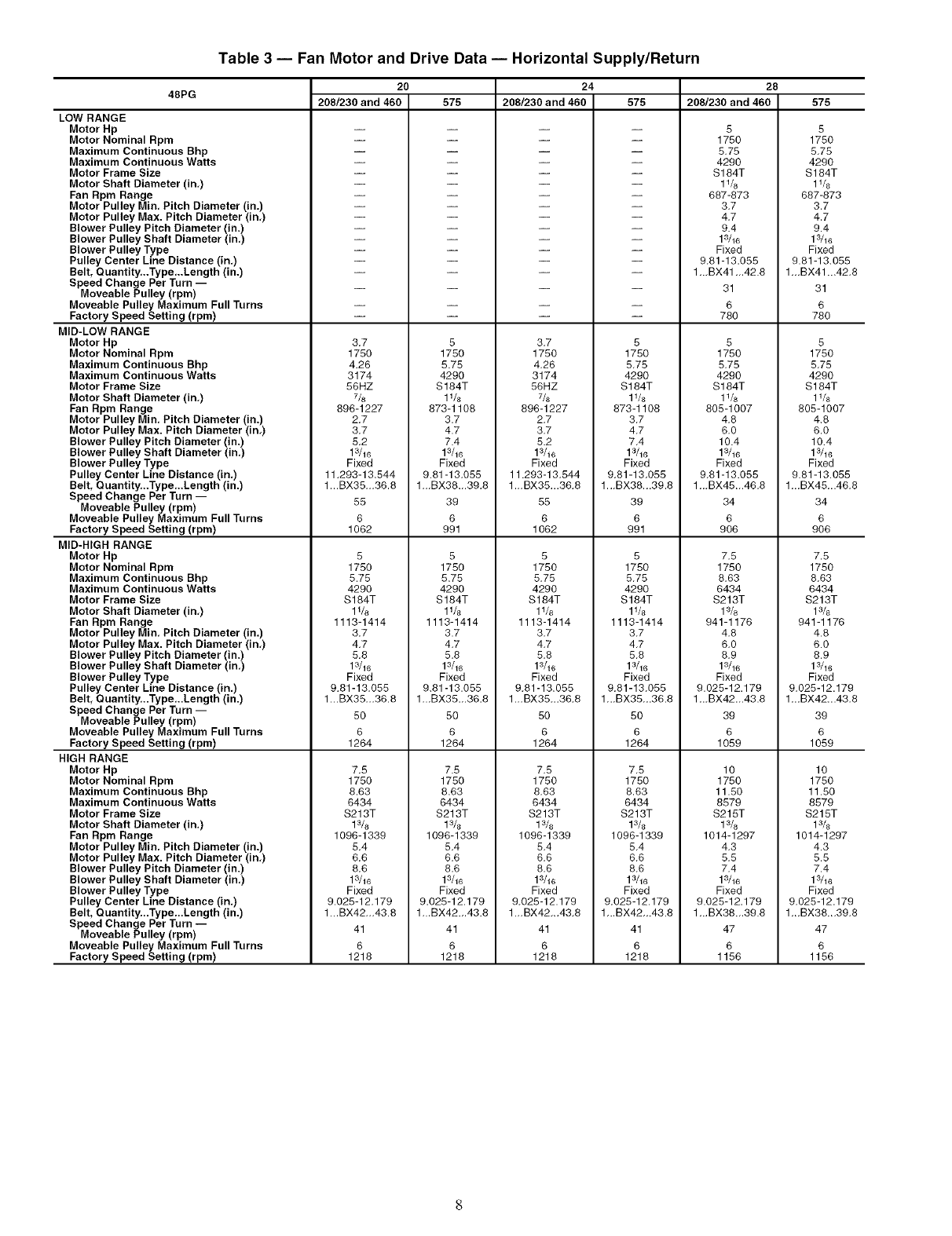
Table 3 -- Fan Motor and Drive Data -- Horizontal Supply/Return
48PG
LOW RANGE
Motor Hp
Motor Nominal Rpm
Maximum Continuous Bhp
Maximum Continuous Watts
Motor Frame Size
Motor Shaft Diameter (in,)
Fan Rpm Range
Motor Pulley Min, Pitch Diameter (in.)
Motor Pulley Max. Pitch Diameter (in,)
Blower Pulley Pitch Diameter (in.)
Blower Pulley Shaft Diameter (in.)
Blower Pulley Type
Pulley Center Line Distance (in,)
20
208/230 and 460 575
24
208/230 and 460 575
28
208/230 and 460
5
1750
5,75
4290
S184T
1%
687-873
3,7
4,7
9.4
13/16
Fixed
9,81-13.055
Belt, Quantity...Type,..Length (in.)
Speed Change Per Turn --
Moveable Pulley (rpm)
Moveable Pulley Maximum Full Turns
Factory Speed Setting (rpm)
MID-LOW RANGE
Motor Hp
Motor Nominal Rpm
Maximum Continuous Bhp
Maximum Continuous Watts
Motor Frame Size
Motor Shaft Diameter (in,)
Fan Rpm Range
Motor Pulley Min, Pitch Diameter (in.)
Motor Pulley Max. Pitch Diameter (in,)
Blower Pulley Pitch Diameter (in.)
Blower Pulley Shaft Diameter (in.)
Blower Pulley Type
Pulley Center Line Distance (in,)
Belt, Quantity...Type,..Length (in.)
Speed Change Per Turn --
Moveable Pulley (rpm)
Moveable Pulley Maximum Full Turns
Factory Speed Setting (rpm)
MID-HIGH RANGE
Motor Hp
Motor Nominal Rpm
Maximum Continuous Bhp
Maximum Continuous Watts
Motor Frame Size
Motor Shaft Diameter (in,)
Fan Rpm Range
Motor Pulley Min. Pitch Diameter (in.)
Motor Pulley Max. Pitch Diameter (in,)
Blower Pulley Pitch Diameter (in.)
Blower Pulley Shaft Diameter (in,)
Blower Pulley Type
Pulley Center Line Distance (in.)
Belt, Quantity...Type...Length (in.)
3,7
1750
4.26
3174
56HZ
7/8
896-1227
2.7
3,7
5,2
13/16
Fixed
11,293-13.544
1_.BX35._36.8
55
6
1062
5
1750
5.75
4290
$184T
1V8
1113-1414
3,7
4,7
5,8
13/16
Fixed
9,81-13,055
1...BX35,,,36.8
5
1750
5.75
4290
S184T
1V8
873-1108
3.7
4.7
7.4
13/16
Fixed
9.81-13.055
1_.BX38_.39.8
39
6
991
5
1750
5.75
4290
S184T
1V8
1113-1414
3.7
4.7
5.8
13/16
Fixed
9.81-13.055
1...BX35...36.8
3,7
1750
4,26
3174
56HZ
7/8
896-1227
2.7
3,7
5.2
13/16
Fixed
11.293-13.544
1._BX35...36,8
55
6
1062
5
1750
5,75
4290
$184T
11/8
1113-1414
3,7
4,7
5,8
13/le
Fixed
9,81-13.055
1.,,BX35,..36,8
5
1750
5,75
4290
S184T
11/8
873-1108
3,7
4,7
7,4
13/16
Fixed
9,81-13,055
1._BX38.,.39.8
39
6
991
5
1750
5,75
4290
S184T
11/s
1113-1414
3,7
4,7
5,8
13/16
Fixed
9,81-13,055
1,.,BX35,,.36.8
1..,BX41 .,.42.8
31
6
78O
5
1750
5,75
4290
$184T
11/8
805-1007
4.8
6.0
10.4
13/16
Fixed
9,81-13.055
1_,BX45_.46.8
34
6
906
7,5
1750
8,63
6434
S213T
13/8
941-1176
4.8
6.0
8.9
13/16
Fixed
9.025-12.179
1,.,BX42.,.43.8
Speed Change Per Turn --
Moveable Pulley (rpm)
Moveable Pulley Maximum Full Turns
Factory Speed Setting (rpm)
HIGH RANGE
Motor Hp
Motor Nominal Rpm
Maximum Continuous Bhp
Maximum Continuous Watts
Motor Frame Size
Motor Shaft Diameter (in.)
Fan Rpm Range
Motor Pulley Min. Pitch Diameter (in.)
Motor Pulley Max. Pitch Diameter (in,)
Blower Pulley Pitch Diameter (in.)
Blower Pulley Shaft Diameter (in,)
Blower Pulley Type
Pulley Center Line Distance (in.)
Belt, Quantity...Type...Length (in.)
Speed Change Per Turn --
Moveable Pulley (rpm)
Moveable Pulley Maximum Full Turns
Factory Speed Setting (rpm)
5O
6
1264
7,5
1750
8.63
6434
$213T
1096-1339
5,4
6,6
8,6
13/16
Fixed
9.025-12,179
1...BX42,..43.8
41
6
1218
5O
6
1264
7.5
1750
8.63
6434
S213T
13&
1096-1339
5,4
6.6
8.6
13/16
Fixed
9.028-12.179
1...BX42...43.8
41
6
1218
5O
6
1264
7,5
1750
8.63
6434
$213T
13/s
1096-1339
5,4
6,6
8,6
13/le
Fixed
9,025-12.179
1.,.BX42,..43,8
41
6
1218
5O
6
1264
7,5
1750
8.63
6434
S213T
1096-1339
5,4
6,6
8,6
13/16
Fixed
9,025-12.179
1,..BX42,..43.8
41
6
1218
39
6
1059
lO
175 o
11.5o
8579
S215T
1%
1014-1297
4,3
5,5
7,4
13/16
Fixed
9.028-12.179
1,..BX38.,.39.8
47
6
1156
575
5
1750
5,75
4290
S184T
11/s
687-873
3.7
4.7
9.4
13/16
Fixed
9.81-13.055
1_,BX41 ...42,8
31
6
78O
5
1750
5,75
4290
S184T
11/8
805-1007
4.8
6.0
10.4
13/16
Fixed
9.81-13.055
1..,BX45...46,8
34
6
906
7.5
1750
8,63
6434
S213T
941-1176
4.8
6.0
8.9
Fixed
9,025-12.179
1,.,BX42...43,8
39
6
1059
lO
175o
11.5o
8579
S215T
13/s
1014-1297
4.3
5.5
7.4
13/16
Fixed
9,025-12.179
1,..BX38...39,8
47
6
1156
ALIGNMENT
HOLE
(IN BASE RAIL)
EDGE FLANGE/;q
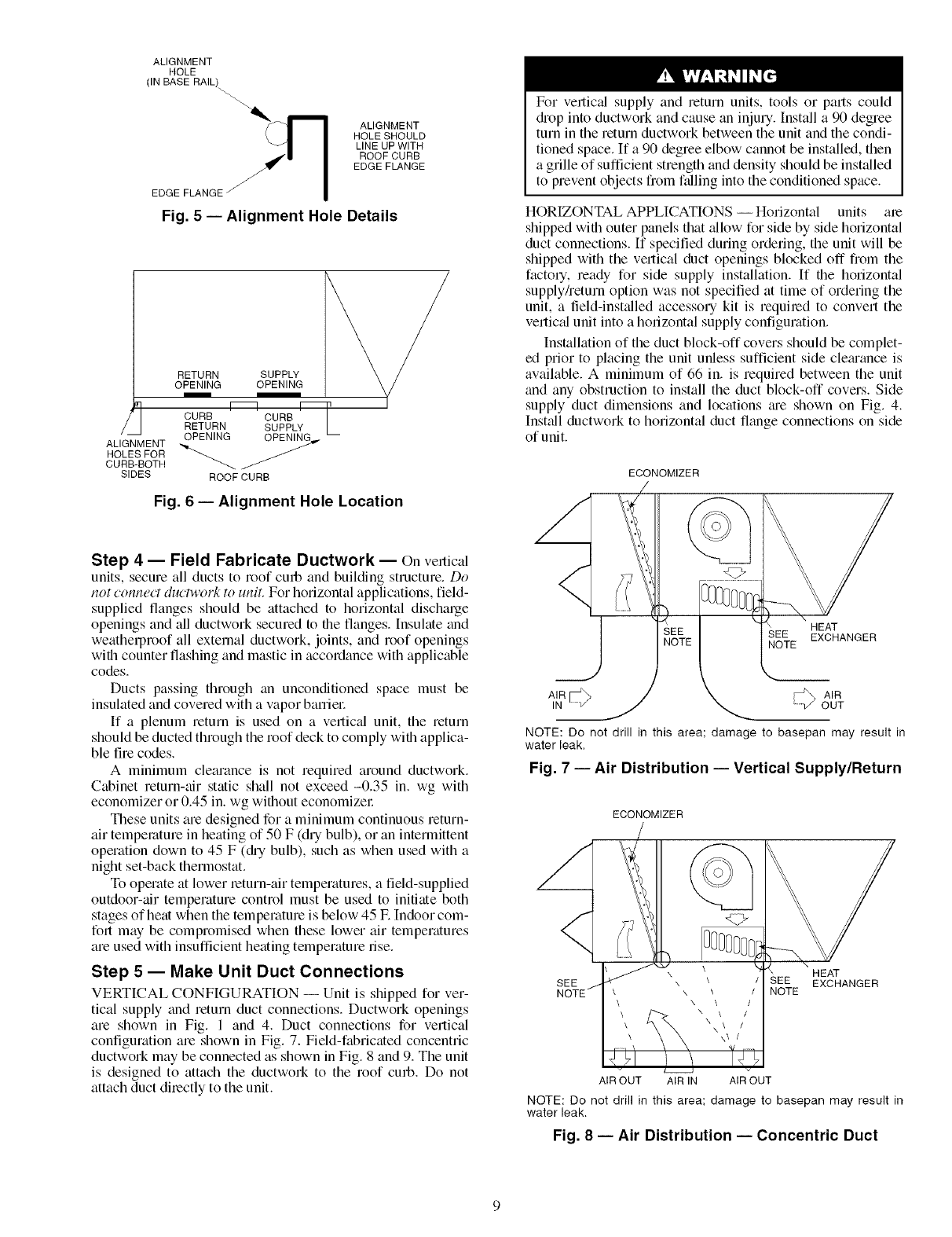
Fig. 5 -- Alignment Hole Details
ALIGNMENT
HOLESHOULD
LINE UP WITH
ROOFCURB
EDGE FLANGE
ALIGNMENT
HOLES FOR
CURB-BOTH
SIDES
RETURN SUPPLY _/
OPENING OPENING
CURB I_CURB[_
RETURN SUPPLY I
OPENING OPENIN_,,.--
ROOF CURB
Fig. 6 -- Alignment Hole Location
Step 4 -- Field Fabricate Ductwork -- On venical
units, secure all ducts to roof curb and building structure. Do
not connect ductwork to unit. For horizontal applications, field-
supplied flanges should be attached to horizontal discharge
openings and all ductwork secured to the flanges. Insulate and
weatherproof all external ductwork, joints, and roof openings
with counter flashing and mastic in accordance with applicable
codes.
Ducts passing through an unconditioned space must be
insulated and covered with a vapor barriel:
If a plenum return is used on a vertic_fl unit, the return
should be ducted through the roof deck to comply with applica-
ble fire codes.
A minimum clearance is not required around ductwork.
Cabinet return-air static shall not exceed -0.35 in. wg with
economizer or 0.45 in. wg without economizel:
These units are designed for a minimum continuous return-
air temperature in heating of 50 F (dry bulb), or an intermittent
operation down to 45 F (di'y bulb), such as when used with a
night set-back thermostat.
To operate at lower leturn-air temperatures, a field-supplied
outdoor-air temperature control must be used to initiate both
stages of heat when the temperature is below 45 E Indoor com-
folt may be compromised when these lower air temperatures
are used with insufficient heating temperature dse.
Step 5 -- Make Unit Duct Connections
VERTICAL CONFIGURATION -- Unit is shipped for ver-
tical supply and return duct connections. Ductwork openings
are shown in Fig. 1 and 4. Duct connections for vertical
configuration are shown in Fig. 7. Field-fabricated concentric
ductwork may be connected as shown in Fig. 8 and 9. The unit
is designed to attach the ductwork to the roof curb. Do not
attach duct directly to the unit.
For vertic'A supply and return units, tools or pmls could
diop into ductwork and cause an injury. Install a 90 degree
turn in the return ductwork between the unit and the condi-
tioned space. If a 90 degree elbow cannot be installed, then
a grille of sufficient strength and density should be installed
to prevent objects fiom ftdling into the conditioned space.
HORIZONTAL APPLICATIONS -- Horizontal units are
shipped with outer panels that _dlow for side by side horizontal
duct connections. If specified during ordering, the unit will be
shipped with the vertical duct openings blocked off from the
factory, ready for side supply installation. If the horizontal
supplyheturn option was not specified at time of ordering the
unit, a field-installed accessory kit is requiled to convert the
vertical unit into a horizontal supply configuration.
Installation of the duct block-off covers should be complet-
ed prior to placing the unit unless sufficient side cletu'ance is
available. A minimum of 66 in. is required between the unit
and any obstruction to install the duct block-off covers. Side
supply duct dimensions and locations tue shown on Fig. 4.
Install ductwork to horizontal duct flange connections on side
of unit.
ECONOMIZER
\ HEAT
SEE EXCHANGER
NOTE
I R@ AIR
'V" OUT
NOTE: Do not drill in this area; damage to basepan may result in
water leak.
Fig. 7 -- Air Distribution -- Vertical Supply/Return
ECONOMIZER
SEE SEE HEAT
EXCHANGER
_OTE
AIR OUT AIR IN AIR OUT
NOTE: Do not drill in this area; damage to basepan may result in
water leak.
Fig. 8 -- Air Distribution -- Concentric Duct
/
BAFFLE
NOTE: Dimensions A, A', B, and B' are obtainedfrom field-supplied
ceiling diffuser.
;, Shaded areas indicate block-off pans.
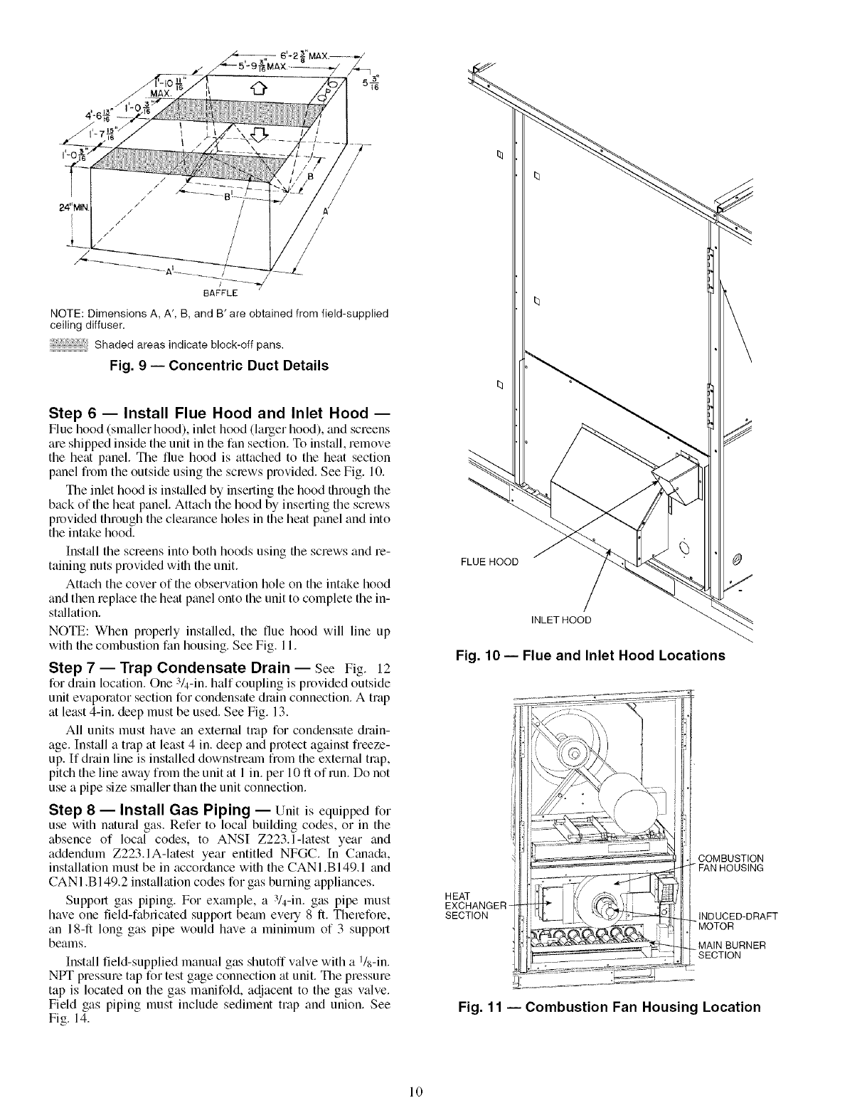
Fig. 9 -- Concentric Duct Details
Step 6 -- Install Flue Hood and Inlet Hood --
Flue hood (smaller hood), inlet hood (larger hood), _mdscreens
are shipped inside the unit in the fan section. To install, remove
the heat panel. Tile flue hood is attached to the heat section
panel from the outside using file screws provided. See Fig. 10.
The inlet hood is installed by inserting the hood through the
back of the heat panel. Attach the hood by inserting the screws
provided through the clearance holes in the heat panel and into
the intake hood.
Inst_dl the screens into both hoods using the screws and re-
taining nuts provided with the unit.
Attach the cover of the obserwttion hole on the intake hood
and then replace the heat panel onto the unit to complete the in-
st_dlation.
NOTE: When properly installed, the flue hood will line up
with the combustion fan housing. See Fig. 11.
Step 7 -- Trap Condensate Drain -- See Fig. 12
for drain location. One 3/4-in. half coupling is provided outside
unit evaporator section for condensate drain connection. A trap
at least 4-in. deep must be used. See Fig. 13.
All units must have an external trap for condensate drain-
age. Install a trap at least 4 in. deep and protect against freeze-
up. If drain line is installed downstremn from the external trap,
pitch the line away from the unit at 1 in. per 10 fl of run. Do not
use a pipe size smaller than the unit connection.
Step 8 -- Install Gas Piping -- Unit is equipped for
use with natural gas. Refer to local building codes, or in the
absence of local codes, to ANSI Z223.1-1atest year and
addendum Z223.1A-latest year entitled NFGC. In Canada,
installation must be in accordance with the CANI .B149.1 and
CAN 1.B 149.2 installation codes for gas burning appliances.
Support gas piping. For example, a 3/4-in. gas pipe must
have one field-fabricated support bemn eve U8 fi. Therefore,
an 18-1l long gas pipe would have a minimum of 3 support
beams.
Install field-supplied manual gas shutoff valve with a l/s-in.
NPT pressure tap for test gage connection at unit. The pressure
tap is located on the gas manifold, adjacent to the gas valve.
Field gas piping must include sediment trap and union. See
Fig. 14.
FLUE HOOD
INLET HOOD
Fig. 10 -- Flue and Inlet Hood Locations
HEAT
EXCHANGER
SECTION
COMBUSTION
FAN HOUSING
INDUCED-DRAFT
MOTOR
MAIN BURNER
-SECTION
Fig. 11 -- Combustion Fan Housing Location
10
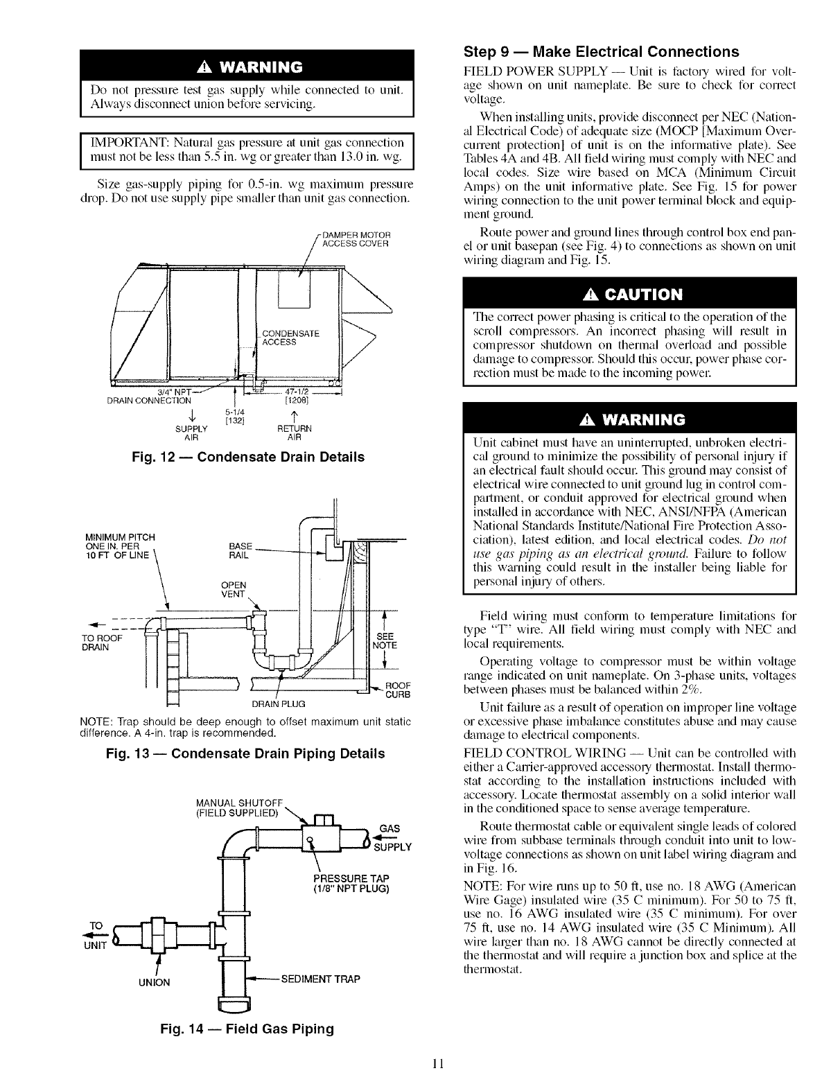
Do not pressme test gas supply while connected to unit.
Always disconnect union before servicing.
IMPORTANT: Natural gas pressure at unit gas connectionmust not be less than 5.5 in. wg or greater than 13.0 in. wg.
Size gas-supply piping for 0.5-in. wg maximum pressure
drop. Do not use supply pipe smaller than unit gas connection.
"DAMPER MOTOR
DRAIN CONNEC ilON [1208[
5-1/4
[132] 1x
SUPPLY RETURN
AIR AIR
Fig. 12- Condensate Drain Details
MINIMUM PITCH
ONE IN. PER
10 FT OF LINE
TO ROOF
DRAIN
t
SEE
NOTE
5_
,,,I_ROOF
CURB
NOTE: Trap should be deep enough to offset maximum unit static
difference. A 4-in. trap is recommended,
Fig. 13- Condensate Drain Piping Details
TO
UNIT
MANUAL SHUTOFF
(FIELD SUP_ GAS
(118" NPT PLUG)
UNlOgaN _--_ ='-"--- SEDIMENT TRAP
Fig. 14 -- Field Gas Piping
Step 9 -- Make Electrical Connections
FIELD POWER SUPPLY- Unit is factory wired for volt-
age shown on unit nameplate. Be sure to check for conect
voltage.
When installing units, provide disconnect per NEC (Nation-
al Electrical Code) of adequate size (MOCP [Maximum Over-
current protectionl of unit is on the informative plate). See
Tables 4A and 4B. All field wiring must comply with NEC and
local codes. Size wire based on MCA (Minimum Circuit
Amps) on the unit informative plate. See Fig. 15 for power
wiring connection to the unit power terminal block and equip-
ment ground.
Route power and ground lines through control box end pan-
el or unit basepan (see Fig. 4) to connections as shown on unit
wiring diagram and Fig. 15.
The correct power phasing is critical to the operation of the
scroll compressors. An incorrect phasing will result in
compressor shutdown on thermal overload and possible
&_mage to complessol: Should this occm: power phase cor-
rection must be made to the incoming powel:
Unit cabinet must have an uninterrupted, unbroken electri-
cal ground to minimize the possibility of peLsonal injury if
an electrical fault should occur This ground may consist of
electric_d wire connected to unit ground lug in control com-
partment, or conduit approved for electric_d ground when
installed in accordance with NEC, ANSI/NFPA (American
National Standiuds Institute/National Fire Protection Asso-
ciation), latest edition, and loc_d electric_d codes. Do not
use gas pil)ing as an electrical ground. Failure to follow
this w_u'ning could result in the installer being liable for
personal injury of others.
Field wiring must conform to temperature limitations for
type "T' wire. All field wiring must comply with NEC and
local requirements.
Operating voltage to compressor must be within voltage
range indicated on unit nameplate. On 3-phase units, voltages
between phases must be balanced within 2%.
Unit failure as a result of operation on improper line voltage
or excessive phase imbalance constitutes abuse and may cause
&image to electrical components.
FIELD CONTROL WIRING -- Unit can be controlled with
either a Carrier-approved accessory thermostat. Install thermo-
stat according to the installation instructions included with
accessory. Locate thermostat assembly on a solid interior wall
in the conditioned space to sense average temperature.
Route thermostat cable or equivalent single leads of colored
wire from subbase terminals through conduit into unit to low-
voltage connections as shown on unit label wiring diagram and
in Fig. 16.
NOTE: For wire runs up to 50 ft, use no. 18 AWG (American
Wire Gage) insulated wire (35 Cminimum). For 50 to 75 ft,
use no. 16 AWG insulated wire (35 Cminimum). For over
75 ft, use no. 14 AWG insulated wire (35 CMinimum). All
wire lalger than no. 18 AWG cannot be directly connected at
the thermostat and will require a junction box and splice at the
thermostat.
11
I TBI
I FIELD I _ F_q
L.......
ow l
(/)a.
F, 1
t
1
I
LEGEND
EQUIP -- Equipment
GND -- Ground
NEC -- National Electrical Code
TB -- Terminal Board
EQUIP GND
NOTE: The maximum wire size for TB1 is 2/0.
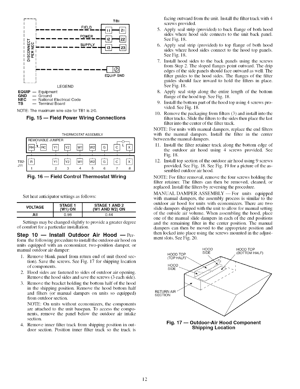
Fig. 15 -- Field Power Wiring Connections
THERMOSTAT ASSEMBLY
I I I I I I I I
TB2- 1_ [_ [_ [_ [] [_ [_ [_8
Jll 2 3 4 5 6 7
Fig. 16- Field Control Thermostat Wiring
Set heat anticipator settings as follows:
STAGE 1STAGE 1 AND 2
VOLTAGE (Wl) ON (W1 AND W2) ON
All 0.98 0.44
Settings may be changed slightly to provide a greater degree
of comfort for a particular installation.
Step 10 -- Install Outdoor Air Hood --Per-
form the following procedure to install the outdoor-air hood on
units equipped with an economizer, two-position ck+mpel: or
manual outdoor air &+mper:
1. Remove blank panel from return end of unit (hood sec-
tion). Save the screws. See Fig. 17 for shipping location
of components.
2. Hood sides _ue fastened to sides of outdoor air opening.
Remove the hood sides and save the screws (3 each side).
3. Remove the bracket holding the bottom half of the hood
in the shipping position. Remove the hood bottom h+df
and filters (or manual dampers on units so equipped)
from outdoor section.
NOTE: On units without economizers, the components
are attached to the unit basepan. To access the compo-
nents, remove the panel below the outdoor air intake
section.
4. Remove inner filter track from shipping position in out-
door section. Position inner filter track so the track is
facing outward from the unit. Install the filter track with 4
screws provided.
5. Apply se_d strip (provided) to back flange of both hood
sides where hood side connects to the unit back panel.
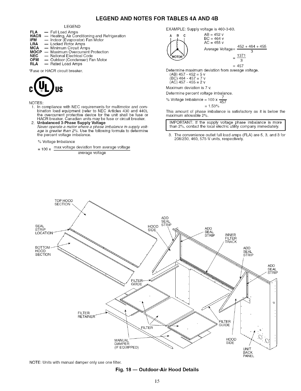
See Fig. 18.
6. Apply seal strip (provided) to top flange of both hood
sides where hood sides connect to the hood top panels.
See Fig. 18.
7. Install hood sides to the back panels using the screws
from Step 2. The sloped flanges point outw_ud. The drip
edges of the side panels should face outward as well. The
filter guides to the hood sides. The flanges of the filter
guides should face inw_u'd to hold the filters in place.
See Fig. 18.
8. Apply seal strip _dong the entire length of the bottom
flange of the hood top. See Fig. 18.
9. [nstall the bottom ptut of the hood top using 4 screws pro-
videdi See Fig. 18.
10. Remove the packaging from tilters (3) and install into the
filter tracks. Slide the filtel.'s to the sides then place the last
filter into the center of the filter track.
NOTE: For units with manmd dampers, replace the end filters
with the manual &_mpers. Install the filter in the center
between the manual dampel.s.
11. Install the filter retainer track along the bottom edge of
the outdoor air hood using 4 screws provided. See
Fig. 18.
12. [nstall top section of the outdoor air hood using 9 screws
provided. See Fig. 18. See Fig. 19 for a pictme of the as-
sembled outdoor air hood.
NOTE: For filter removal, remove the four screws holding the
filter retainel: The filters can then be removed, cleaned, or
replaced. Install the filters by reversing the procedure.
MANUAL DAMPER ASSEMBLY-- For units equipped
with manual dampers, the assembly process is similar to the
outdoor air hood for units with economizers. There me two
slide dampers shipped with the unit to 'allow for manual setting
of the outside air volume. When assembling the hood, place
one of the manual slide dampers in each of the end positions
and the remaining filter in the center position. The manual
dampel.s can then be moved to the appropriate position and
then locked into place using the screws mounted in the adjust-
ment slots. See Fig. 20.
HOOD TOP
(TOP HALF)_
HOOD
SIDE
HOOD HOOD TOP
SIDE BOTTOM HALF)
RETURN AIR
SECTION
Fig. 17 -- Outdoor-Air Hood Component
Shipping Location
12
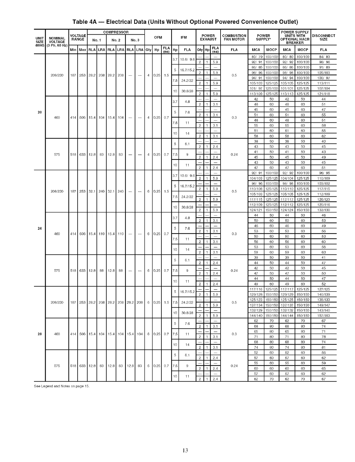
Table 4A -- Electrical Data (Units Without Optional Powered Convenience Outlet)
UNIT
SIZE
48HG
NOMINAL
VOLTAGE
(3 Ph, 80 HZ)
208/230
460
575
208/230
46O
575
208/230
46O
575
COMPRESSOR POWER SUPPLY
VOLTAGE OFM IFM POWER COMBUSTION POWER UNITS WITH
RANGE No. 1 No. 2 No. 3 EXHAUST FAN MOTOR SUPPLY* OPTIONAL HACR
BREAKER
FLA.. _La_MIn Max RLA LRA RLA LRA RLA LRA Qty Hp (ea) Hp FLA Qty Hp FLA MCA MOCP MCA MOCP
80/ 79 100/100 80/ 80 100/100
3.7 10.6/ 9.6 2 1 5.9 92/ 91 100/100 92/ 92 100/100
86/ 85 100/100 86/ 86 100/100
5 16.7/15.2 2 1 5.9 98/ 96 100/100 98/ 98 100/100
187 253 28.2 208 28.2 208 4 0.25 1.5 0.5 94/ 91 100/100 94/ 94 100/100
7.5 24.2/22 2 1 5.9 105/103 125/125 105/105 125/125
101/ 97 125/100 101/101 125/125
10 30.8/28 2 1 5.9 113/109 125/125 113/113 125/125
42 50 42 50
3.7 4.8 2 1 3.1 48 60 48 60
45 60 45 60
5 7.6 2 1 3.1 51 60 51 60
414 506 15.4 104 15.4 104 4 0.25 0.7 0.3 48 60 48 60
7.5 11 2 1 3.1 55 60 55 60
51 60 51 60
10 14 2 1 3.1 58 60 58 60
38 50 38 50
5 6.1 2 1 2.4 43 50 43 50
41 50 41 50
518 633 12.8 83 12.8 83 4 0.25 0.7 7.5 9 0.24
2 1 2.4 45 50 45 50
43 50 43 50
10 11 2 1 2.4 47 60 47 60
92/ 91 100/100 92/ 92 100/100
3.7 10.6/ 9.6 2 1 5.9 104/103 125/125 104/104 125/125
98/ 96 100/100 98/ 98 100/100
5 16.7/15.2 2 1 5.9 110/108 125/125 110/110 125/125
187 253 32.1 240 32.1 240 6 0.25 1.5 0.5 105/103 125/125 105/105 125/125
7.5 24.2/22 2 1 5.9 117/115 125/125 117/117 125/125
112/109 125/125 112/112 125/125
10 30.8/28 2 1 5.9 124/121 150/150 124/124 150/150
44 50 44 50
3.7 4.8 2 1 3.1 50 60 50 60
46 60 46 60
5 7.6 2 1 3.1 53 60 53 60
414 506 15.4 110 15.4 110 6 0.25 0.7 0.3 50 60 50 60
7.5 11 2 1 3.1 56 60 56 60
53 60 53 60
10 14 2 1 3.1 59 60 59 60
39 50 39 50
5 6.1 2 1 2.4 44 50 44 50
42 50 42 50
518 633 12.8 88 12.8 88 6 0.25 0.7 7.5 9 0.24
2 1 2.4 47 50 47 50
44 50 44 50
10 11 2 1 2.4 49 60 49 60
117/116 125/125 117/117 125/125
5 16.7/15.2 2 1 5.9 129/128 150/150 129/129 150/150
125/123 150/150 125/125 150/150
187 253 28.2 208 28.2 208 28.2 208 6 0.25 1.5 7.5 24.2/22 0.5
2 1 5.9 137/134 150/150 137/137 150/150
132/129 150/150 132/132 150/150
10 30.8/28 2 1 5.9 144/140 150/150 144/144 150/150
62 70 62 70
5 7.6 2 1 3.1 68 80 68 80
65 80 65 80
414 506 15.4 104 15.4 104 15.4 104 6 0.25 0.7 7.5 11 0.3
2 1 3.1 71 80 71 80
68 80 68 80
10 14 2 1 3.1 74 80 74 80
52 60 52 60
5 6.1 2 1 2.4 57 60 57 60
55 60 55 60
518 633 12.8 83 12.8 83 12.8 83 6 0.25 0.7 7.5 9 0.24
2 1 2.4 60 60 60 60
57 60 57 60
10 11 2 1 2.4 62 70 62 70
DISCONNECT
SIZE
FLA
84/ 83
98/ 96
91/ 89
105/103
100/ 97
113/111
107/104
121/118
44
51
47
55
51
58
55
62
4O
45
43
49
45
51
96/ 95
110/109
103/102
117/115
112/109
126/123
120/118
133/130
46
53
49
56
53
60
56
63
41
47
45
5O
47
52
127/128
140/139
135/133
148/147
143/140
157/183
67
74
71
78
74
81
56
62
59
65
62
67
See Legend and Notes on page 15.
]3
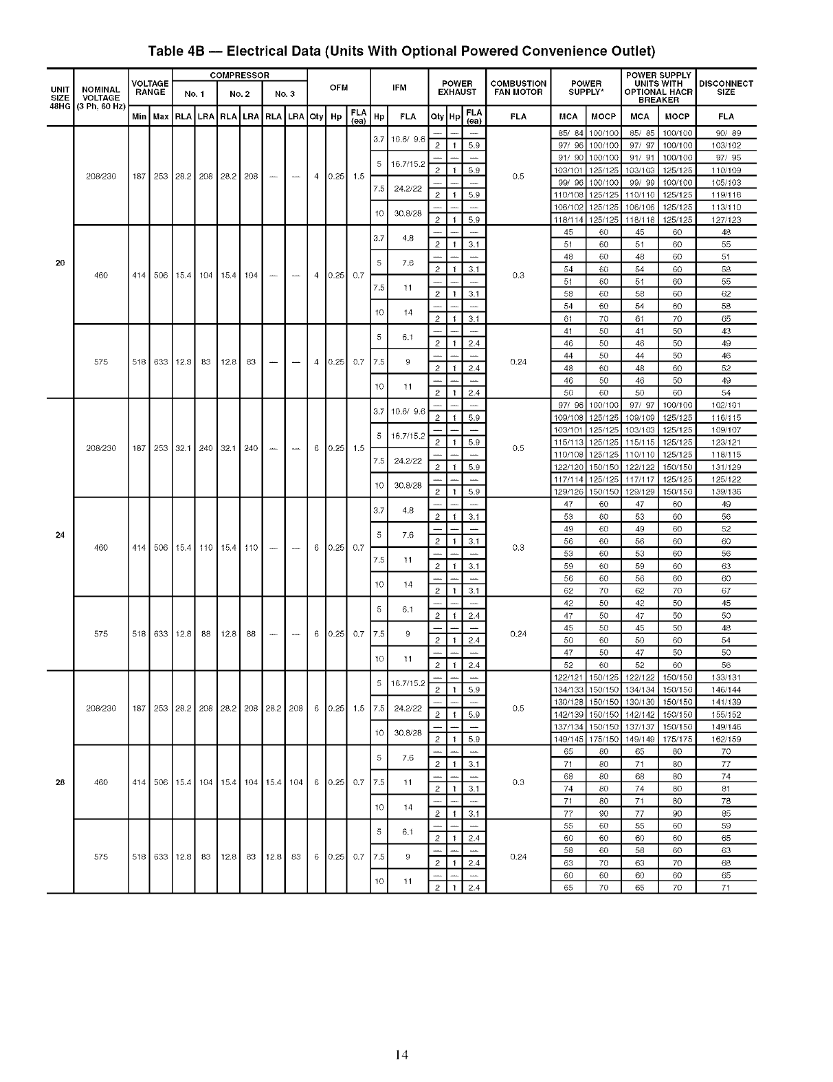
Table 4B -- Electrical Data (Units With Optional Powered Convenience Outlet)
COMPRESSOR
VOLTAGE OFM IFM POWER COMBUSTION POWER
UNIT NOMINAL RANGE NO. 1 NO. 2 NO. 3 EXHAUST FAN MOTOR SUPPLY*
SIZE VOLTAGE
48HG (3 Ph, 60 HZ)
_La_ FLAMIn Max RLA LRA RLA LRA RLA LRA Oty Hp Hp FLA Oty Hp (ea) FLA MCA MOCP
i i
85/ 84 100/100
3.7 10.6/ 9.6 2 1 5.9 97/ 96 100/100
91/ 90 100/100
5 16.7/15.2 2 1 5.9 103/101 125/125
208/230 187 253 28.2 208 28.2 208 4 0.25 1.5 0.5 99/ 96 100/100
7.5 24.2/22 2 1 5.9 110/108 125/125
106/102 125/125
10 30.8/28 2 1 5.9 118/114 125/125
45 60
3.7 4.8 2 1 3.1 51 60
48 60
20 5 7.6 2 1 3.1 54 60
460 414 506 15.4 104 15.4 104 4 0.25 0.7 0.3 51 60
7.5 11 2 1 3.1 58 60
54 60
10 14 2 1 3.1 61 70
41 50
5 6.1 2 1 2.4 46 50
44 50
575 518 633 12.8 83 12.8 63 4 0.25 0.7 7.5 9 0.24
2 1 2.4 48 60
46 50
10 11 2 1 2.4 50 60
97/ 96 100/100
3.7 10.6/ 9.6 2 1 5.9 109/108 125/125
103/101 125/125
5 16.7/15.2 2 1 5.9 115/113 125/125
208/230 187 253 32.1 240 32.1 240 6 0.25 1.5 0.5 110/108 125/125
7.5 24.2/22 2 1 5.9 122/120 150/150
117/114 125/125
10 30.8/28 2 1 5.9 129/126 150/150
47 60
3.7 4.8 2 1 3.1 53 60
49 60
24 5 7.6 2 1 3.1 56 60
460 414 506 15.4 110 15.4 110 6 0.25 0.7 0.3 53 60
7.5 11 2 1 3.1 59 60
56 60
10 14 2 1 3.1 62 70
42 50
5 6.1 2 1 2.4 47 50
45 50
575 518 633 12.8 88 12.8 68 6 0.25 0.7 7.5 9 0.24
2 1 2.4 50 60
47 50
10 11 2 1 2.4 52 60
122/121 150/125
5 16.7/15.2 2 1 5.9 134/133 150/150
130/128 150/150
208/230 187 253 28.2 208 28.2 208 28.2 208 6 0.25 1.5 7.5 24.2/22 0.5
2 1 5.9 142/139 150/150
137/134 150/150
10 30.8/28 2 1 5.9 149/145 175/150
65 80
5 7.6 2 1 3.1 71 80
68 80
28 460 414 506 15.4 104 15.4 104 15.4 104 6 0.25 0.7 7.5 11 0.3
2 1 3.1 74 80
71 80
10 14 2 1 3.1 77 90
55 60
5 6.1 2 1 2.4 60 60
58 60
575 518 633 12.8 83 12.8 63 12.8 83 6 0.25 0.7 7.5 9 0.24
2 1 2.4 63 70
60 60
10 11 2 1 2.4 65 70
POWER SUPPLY
UNITS WITH DISCONNECT
OPTIONAL HACR SIZE
BREAKER
MCA MOCP FLA
85/ 85 100/100 90/ 89
97/ 97 100/100 103/102
91/ 91 100/100 97/ 95
103/103 125/125 110/109
99/ 99 100/100 105/103
110/110 125/125 119/116
106/106 125/125 113/110
118/118 125/125 127/123
45 60 48
51 60 55
48 60 51
54 60 58
51 60 55
58 60 62
54 60 58
61 70 65
41 50 43
46 50 49
44 50 46
48 60 52
46 50 49
50 60 54
97/ 97 100/100 102/101
109/109 125/125 116/115
103/103 125/125 109/107
115/115 125/125 123/121
110/110 125/125 118/115
122/122 150/150 131/129
117/117 125/125 125/122
129/129 150/150 139/136
47 60 49
53 60 56
49 60 52
56 60 60
53 60 56
59 60 63
56 60 60
62 70 67
42 50 45
47 50 50
45 50 48
50 60 54
47 50 50
52 60 56
122/122 150/150 133/131
134/134 150/150 146/144
130/130 150/150 141/139
142/142 150/150 155/152
137/137 150/150 149/146
149/149 175/175 162/159
65 80 70
71 80 77
68 80 74
74 80 61
71 80 78
77 90 65
55 60 59
60 60 65
58 60 63
63 70 68
60 60 65
65 70 71
14
LEGEND AND NOTES FOR TABLES 4A AND 4B
LEGEND
FLA -- Full Load Amps
HAOR -- Heating, Air Conditioning and Refrigeration
IFM -- Indoor (Evaporator) Fan Motor
LRA -- Locked Rotor Amps
MCA -- Minimum Circuit Amps
MOOP -- Maximum Overcurrent Protection
NEC -- National Electrical Code
OFM -- Outdoor (Condenser) Fan Motor
RLA -- Rated Load Amps
*Fuse or HACR circuit breaker.
NOTES:
1. In compliance with NEC requirements for multimotor and com-
bination load equipment (refer to NEC Articles 430 and 440),
the overcurrent protective device for the unit shall be fuse or
HACR breaker. Canadian units may be fuse or circuit breaker.
2. Unbalanced 3-Phase Supply Voltage
Never operate a motor where a phase imbalance in supply volt-
age is greater than 2%. Use the following formula to determine
the percent voltage imbalance.
% Voltage Imbalance
= 100 x max voltage deviation from average voltage
average voltage
EXAMPLE: Supply voltage is 460-3-60.
AB C AB = 452 v
(_ BC = 464 v
AC = 456 v
Average Voltage= 452 + 464 + 456
3
1371
3
= 457
Determine maximum deviation from average voltage.
(AB) 467 - 462 = 5 v
(BC) 464 - 457 = 7 v
(AC) 457 -456 = 2 v
Maximum deviation is 7 v.
Determine percent voltage imbalance.
7
% Voltage Imbalance = 100 x 45"_"
= 1.53%
This amount of phase imbalance is satisfactory as it is below the
maximum allowable 2%.
I MPORTANT: If the supply voltage phase imbalance is more I
than 2%, contact the local electric utility company immediately. I
3. The convenience outlet full load amps (FLA) are 5, 3, and 3 for
208/230,460, 575-V units, respectively.
TOP HOOD
SECTION
SEAL
STRIP
LC
HOOD
SECTION
ADD
SEAL
HOOD STRIP
SIDE ADD
STRIP INNER
FILTER
ADD
SEAL
STRIP
ADD
SEAL
GUIDE
FILTER
RETAINER
FILTER
MANUAL
DAMPER
(IF EQUIPPED)
NOTE: Units with manual damper only use one filter.
Fig. 18 -- Outdoor-Air Hood Details
HOOD
SIDE
UNIT
BACK
PANEL
15
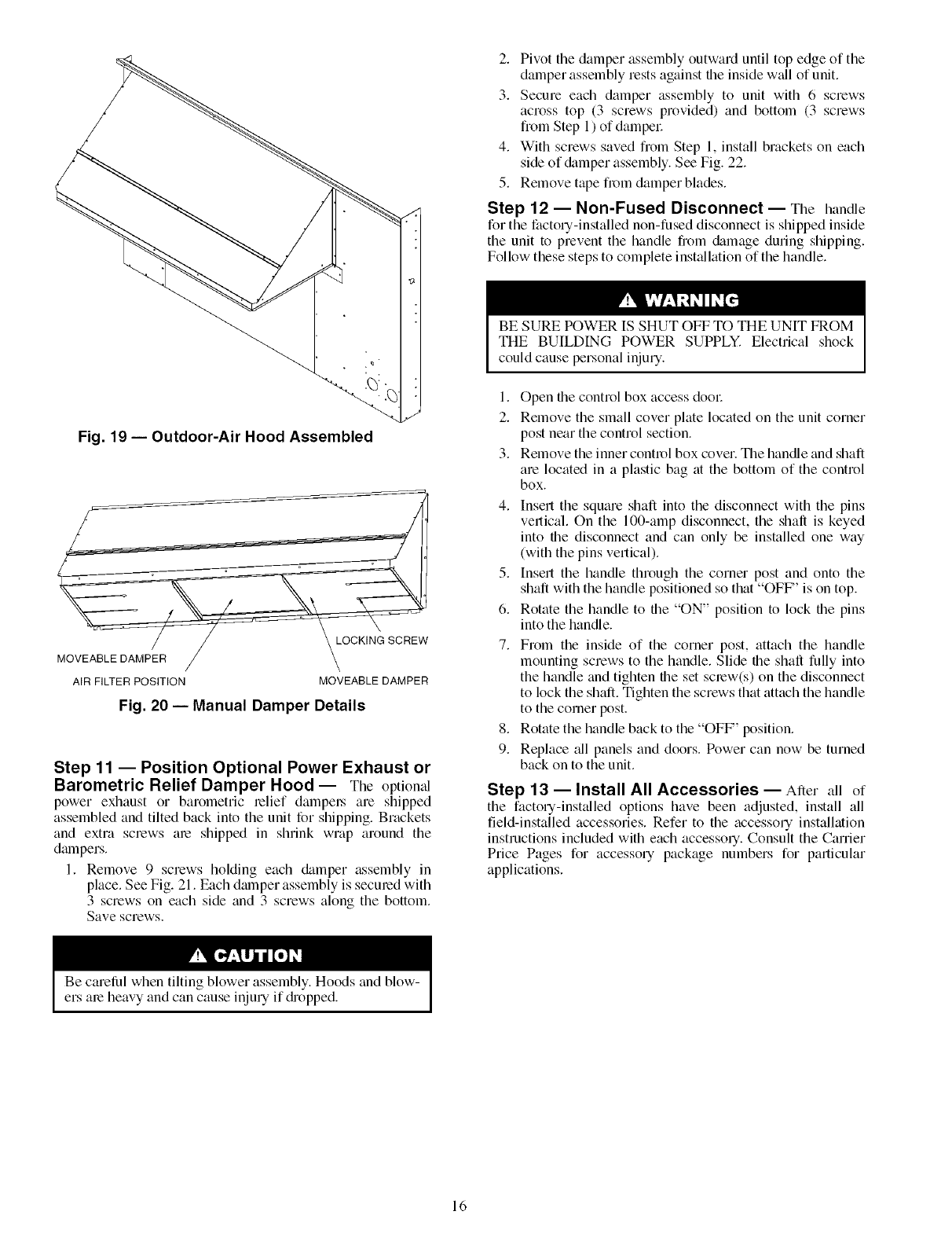
Fig. 19 -- Outdoor-Air Hood Assembled
w
MOVEABLE DAMPER j
AIR FILTER POSITION MOVEABLE DAMPER
Fig. 20 -- Manual Damper Details
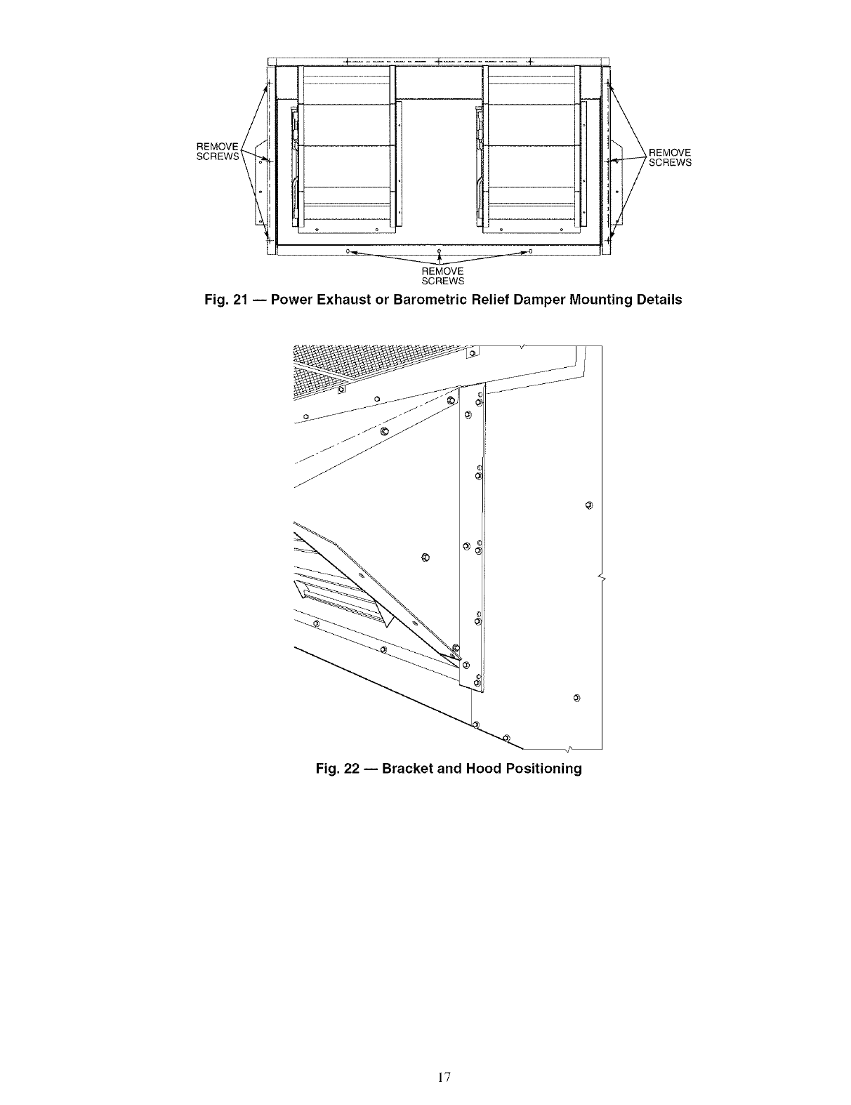
Step 11 -- Position Optional Power Exhaust or
Barometric Relief Damper Hood-- The optional
power exhaust or barometric relief dampel,'s are shipped
assembled and tilted back into the unit for shipping. Brackets
and extra screws am shipped in shrink wrap around the
dalnpers,
1, Remove 9 screws holding each &tmper assembly in
place, See Fig, 21. Each dmnper assembly is secured with
3 screws on each side and 3 screws along the bottom,
Save screws.
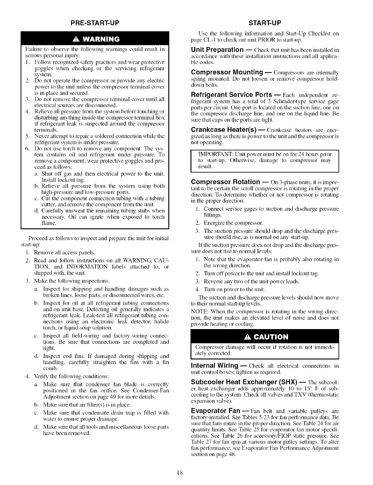
2. Pivot the damper assembly outward until top edge of the
damper assembly rests against the inside wall of unit.
3. Secure each damper assembly to unit with 6 screws
across top (3 screws provided) and bottom (3 screws
from Step 1) of dampel:
4. With screws saved from Step 1, install brackets on each
side of &tmper assembly. See Fig. 22.
5. Remove tape fi'om damper blades.
Step 12 -- Non-Fused Disconnect -- The handle
for the factory-installed non-fused disconnect is shipped inside
the unit to prevent the handle from &image during shipping.
Follow these steps to complete inst_dlation of the handle.
BE SURE POWER IS SHUT OFF TO THE UNIT FROM
THE BUILDING POWER SUPPLY. Electrical shock
could cause personal injury.
1. Open the control box access dool:
2. Remove the small cover plate located on the unit corner
post near the control section.
3. Remove the inner control box cover. Tile handle and shaft
are located in a plastic bag at the bottom of the control
box.
4. Insert the square shaft into the disconnect with the pins
vertical. On the 100-amp disconnect, the shaft is keyed
into the disconnect and can only be installed one way
(with the pins vertical).
5. [nsert the handle through the corner post and onto the
shaft with the handle positioned so that "OFF' is on top.
6. Rotate the handle to the "ON" position to lock the pins
into the handle.
7. From the inside of the corner post, attach the handle
mounting screws to the handle. Slide the shaft fully into
the handle and tighten the set screw(s) on the disconnect
to lock the shaft. Tighten the screws that attach the handle
to the comer post.
8. Rotate the handle back to the "OFF" position.
9. Replace all panels and doors. Power can now be turned
back on to the unit.
Step 13 --Install All Accessories- After all of
the factory-installed options have been adjusted, install all
field-installed accessories. Refer to the accesso Uinstallation
instructions included with each accesso q. Consult the Carrier
Price Pages for accesso Upackage numbers for particular
applications.
Be camlhl when tilting blower assembly. Hoods and blow-
ers are heavy and can cause injury if dropped.
16
REMOVE (
SCREWS
,,,=,-.,4_0
},REMOVE
SCREWS
REMOVE
SCREWS
Fig. 21 -- Power Exhaust or Barometric Relief Damper Mounting Details
J
J
@
©
Fig. 22 -- Bracket and Hood Positioning
17
PRE-START-UP
F;filure to observe the following warnings could result in
serious personal injury.
1. Follow recognized safety practices and we;u protective
goggles when checking or the servicing refrigerant
system.
2. Do not operate the compressor or provide any electric
power to the unit unless the compressor terminal cover
is in place and secured.
3. Do not remove the compressor terminal cover until all
electrical sources _ue disconnected.
4. Relieve all pressure from file system before touching or
disturbing anything inside the compressor terminal box
if refrigerant leak is suspected around the compressor
terminals.
5. Never attempt to repair a soldered connection while the
refrigerant system is under pressure.
6. Do not use torch to remove any component. The sys-
tem contains oil and refrigerant under pressure. To
remove a component, wear protective goggles and pro-
ceed as follows:
a. Shut off gas and then electrical power to the unit.
Install lockout tag.
b. Relieve all pressure from the system using both
high-pressure and low-pressure poris.
c. Cut the component connection tubing with a tubing
cuttel: and remove the component from the unit.
d. Carefully unsweat the remaining tubing stubs when
necessary. Oil can ignite when exposed to torch
flalne.
Proceed as follows to inspect and plepale the unit for initial
st_ut-up:
1. Remove all access panels.
2. Read and follow instructions on all WARNING CAU-
TION, and INFORMATION labels attached to, or
shipped with, the unit.
3. Make the following inspections:
a. Inspect for shipping and handling damages such as
broken lines, loose parts, or disconnected wires, etc.
b. Inspect for oil at all refrigerant tubing connections
and on unit base. Detecting oil generally indicates a
refrigerant leak. Leak-test all refiigemnt tubing con-
nections using an electronic leak detectol: halide
torch, or liquid-soap solution.
c. Inspect all field-wiring and factoly-wiring connec-
tions. Be sure that connections are completed and
tight.
d. Inspect coil fins. If damaged during shipping and
handling, carefully straighten the fins with a tin
comb.
4. Verify the following conditions:
a. Make sure that condenser fan blade is correctly
positioned in the fan orifice. See Condenser-Fan
Adjustment section on page 49 for more details.
b. M_d_e sure that air filter(s) is in place.
c. Make sure that condensate drain trap is filled with
water to ensure proper di'ainage.
d. Make sure that all tools and miscellaneous loose parts
have been removed.
START-UP
Use the following inforlnation and Start-Up Checklist on
page CL-I to check out unit PRIOR to start-up.
Unit Preparation -- Check that unit has been installed in
accordance with these installation instructions and all applica-
ble codes.
Compressor Mounting- Compressors are internally
spring mounted. Do not loosen or remove compressor hold-
down bolts.
Refrigerant Service Ports-- Each independent re-
frigerant system has a total of 3 Schmder-type service gage
ports per circuit. One port is located on the suction line, one on
the compressor dischmge line, and one on the liquid line. Be
sure that caps on the ports are tight.
Crankcase Heater(s)- Crankcase heaters are ener-
gized as long as there is power to the unit and the compressor is
not operating.
IMPORTANT: Unit power must be on for 24 hom_ prior
to start-up. Otherwise, damage to compressor may
result.
Compressor Rotation -- On 3-phase units, it is impor-
tant to be certain the scroll compressor is rotating in the proper
direction. To determine whether or not compressor is rotating
in the proper direction:
1. Connect service gages to suction and discharge pressure
fittings.
2. Energize the compressoc
3. The suction pressure should diop and the discharge pres-
sure should rise, as is normal on any start-up.
If the suction pressure does not drop and the discharge pres-
sure does not rise to normal levels:
1. Note that the evaporator fan is probably also rotating in
the wrong direction.
2. Turn off power to the unit and install lockout tag.
3. Reverse any two of the unit power leads.
4. Turn on power to the unit.
The suction and discharge pressure levels should now move
to their normal start-up levels.
NOTE: When the compressor is rotating in the wrong direc-
tion, the unit makes an elevated level of noise and does not
provide heating or cooling.
Compressor damage will occur if rotation is not immedi-
ately corrected.
Internal Wiring- Check all electric_d connections in
unit control boxes; tighten as required.
Subcooler Heat Exchanger (SHX) -- The subcool-
er heat exchanger adds approximately 10 to 15° F of sub-
cooling to the system. Check all valves and TXV (thermostatic
expansion valve).
Evaporator Fan- Fan belt and vmiable pulleys are
factory-installedi See Tables 5-23 for fan performance data. Be
sure that fans rotate in the proper direction. See Table 24 for air
quantity limits. See Table 25 for evaporator fan motor specifi-
cations. See Table 26 for accessory/FIOP static pressure. See
Table 27 for fan rpm at various motor pulley settings. To alter
fan performance, see Evaporator Fan Performance Adjustment
section on page 48.
18
Condenser Fans and Motors -- Condenser fans and
motol.'s ;u'e factory set. Refer to Condensel;Fan Adjustment
section (page 49) as required.
Return-Air Filters- Check that correct filters are in-
stalled in filter tracks (see Table 1 ). Do not operate unit without
return-air filters.
NOTE: For units with 4-in. filter option, units ale shipped with
standard 2-in. filtel.s. To install 4-in. filters, the filter spacers
must be removed.
Outdoor-Air Inlet Screens -- Outdoor-air inlet screens
must be in place before operating unit.
Gas Heat -- Verify gas pressures before turning on heat as
follows:
1. Turn off field-supplied manual gas stop, located external
to unit.
2. Connect pressure gage to supply gas tap, located on field-
supplied manual shutoff valve (see Fig. 14).
3.
4.
6.
7.
Connect pressure gage to manifold pressure tap.
Turn on field-supplied manual gas stop. Temporarily
install the jumper wile between "R" and "WI" on TB2.
Set thermostat to HEAT and raise set point until heat
comes on.
After the unit has run for several minutes, verify the sup-
ply gas pressure is between 5.5 in. wg to 13.0 in. wg, and
the manifold pressure is 2.95 in. wg on horizontal dis-
chtuge applications and 3.00 on vertical dischtuge appli-
cations. If manifold pressure must be adjusted, refer to
Gas Valve Adjustment section.
NOTE: Supply gas pressure must not exceed 13.0 in. wg.
Set themlostat to OFE
Remove jumper wire if the unit will be operating under
thermostat mode.
Return thermostat to desired set point.
AIRFLOW
(Cfm)
5000
5500
6000
6500
7000
7500
8000
8500
9000
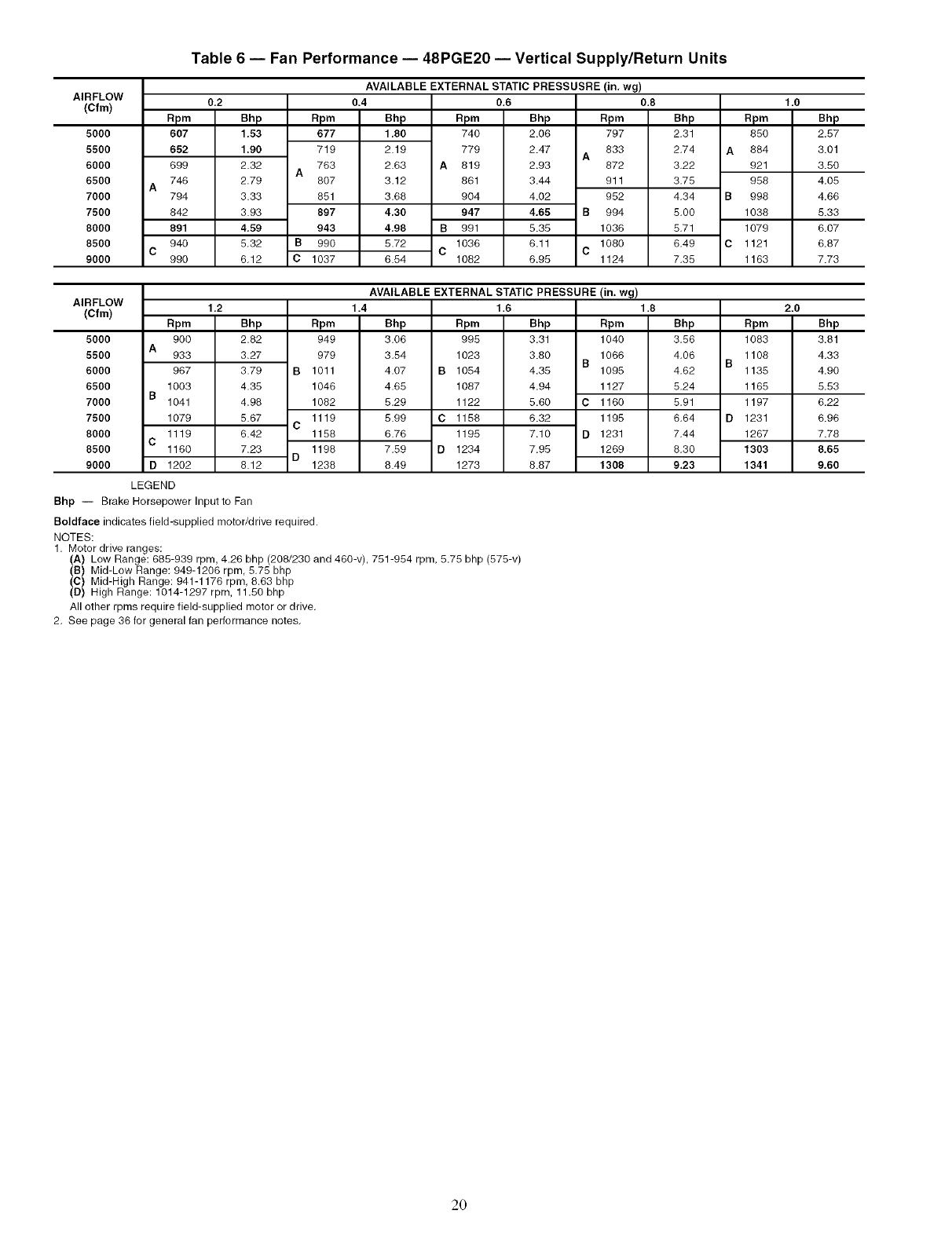
Table 5 -- Fan Performance -- 48PGD20 Vertical Supply/Return Units
Rpm
590
633
677
722
767
813
859
906
952
0,2
Bhp
1,47
1.82
2,21
2.67
3.17
3.74
4.36
5,05
5.81
Rpm
663
703
744
A786
828
871
915
B 959
C 1004
AVAILABLE EXTERNAL STATIC PRESSURE (in. wg)
0.80,4
Bhp
1.74
2,11
2.53 A
3.01
3.53
4.12
4.77 B
5,47 C
6.25
Rpm
727
764
803
842
883
924
966
1008
1051
0.6
Bhp
2,01
2,40
2,84
3,33
3,88
4.48
5,15
5,87
6,67
Rpm
786
820
A857
894
933
972
B1012
1053
C1095
Bhp
2.26
2.67
3.13
3.64
4.21
4.83
5.52
6.26
7.07
Rpm
84O
A872
9O7
942
979
B1017
1056
C 1096
1136
1.0
Bhp
2.52
2.94
3.42
3.95
4.53
5.18
5.88
6.64
7.47
AIRFLOW
(Cfm)
5000
5500
6000
6500
7000
7500
8000
8500
9000
Rpm
891
A921
954
988
B1024
1060
1098
C 1137
1176
1.2
Bhp
2.77
3.21
3.70
4.25
4.85
5.51
6.23
7.01
7.86
Rpm
940
968
B 999
1032
1066
1101
C 1138
1175
D 1214
AVAILABLE EXTERNAL STATIC PRESSURE (in, wg)
1,81.4
Bhp
3.02
3,48
3,99 B
4,55
5,17
5,84 C
6,58
7,38 D
8,24
Rpm
987
1014
1042
1073
1106
1140
1176
1212
1250
1.6
Bhp
3,27
3,74
4,27
4.85
5,48
6.17
6.92
7.74
8.61
Rpm
1032
1057
B1084
1114
C 1145
1178
1213
D1248
1285
Bhp
3.52
4.01
4.55
5.14
5.79
6.50
7.26
8.09
8.99
Rpm
1076
1099
B1125
1153
1183
1215
D1249
1283
1319
2.0
Bhp
3,77
4,27
4,83
5,44
6,10
6,82
7,60
8,45
9.36
LEGEND
Bhp -- Brake Horsepower Inputto Fan
Boldface indicates field-supplied motor/drive required.
NOTES:
1. Motor drive ranges:
(A) Low Range: 685-939 rpm, 4.26 bhp (208/230 and 460-v), 751-954 rpm, 5.75 bhp (575-v)
(B) Mid-Low Range: 949-1206 rpm, 5.75 bhp
(C) Mid-High Range: 941-1176 rpm, 8.63 bhp
(D) High Range: 1014-1297 rpm, 11,50 bhp
All other rpms require field-supplied motor or drive.
2. Bee page 36 for general fan performance notes.
19
AIRFLOW
(Cfm)
5000
5500
6000
6500
7000
7500
8000
8500
9000
Table 6 -- Fan Performance -- 48PGE20 -- Vertical Supply/Return Units
Rpm
607
652
699
746
794
842
891
940
990
0,2
Bhp
1.53
1.90
2.32
2.79
3.33
3.93
4,59
5.32
6.12
Rpm
677
719
763
A8O7
851
897
943
B 990
C 1037
AVAILABLEEXTERNALSTATICPRESSUSRE(in, wg)
0.4 0.6 0.8
Bhp
1,80
2.19
2.63
3.12
3.68
4.30
4.98
5.72
6.54
B
C
Rpm
740
779
819
861
904
947
991
1036
1082
Bhp
2.06
2.47 A
2.93
3.44
4.02
4,65 B
5.35
6.11 C
6.95
apm
797
833
872
911
952
994
1036
1080
1124
Bhp
2,31
2.74 A
3.22
3.75
4.34 B
5.00
5.71
6.49 C
7.35
1.0
Rpm Bhp
850 2.57
884 3.01
921 3.50
958 4.05
998 4.66
1038 5.33
1079 6.07
1121 6.87
1163 7.73
AIRFLOW
(Cfm)
5000
5500
6000
6500
7000
7500
8000
8500
9000
Rpm
900
933
967
1003
B1041
1079
1119
C1160
D 1202
1.2
Bhp
2.82
3.27
3.79
4.35
4.98
5.67
6.42
7.23
6.12
Rpm
949
979
B 1011
1046
1082
1119
C1158
1198
D1238
AVAILABLE EXTERNAL STATIC PRESSURE (in. wg)
1.4
Bhp
3.06
3.54
4.07 B
4.65
5.29
5.99 C
6.76
7.59 D
8.49
1.6
Rpm
995
1023
1054
1087
1122
1158
1195
1234
1273
Bhp Rpm
3.31 1040
3.60 1066
B
4.35 1095
4.94 1127
5.60 C 1160
6.32 1195
7.10 D 1231
7.95 1269
8.67 1308
1.8
Bhp Rpm
3.56 1083
4.06 1106
B
4.62 1135
5.24 1165
5.91 1197
6,64 D1231
7.44 1267
8.30 1303
9,23 1341
2.0
Bhp
3.81
4.33
4.90
5.53
6.22
6.96
7.78
8,65
9.60
LEGEND
Bhp -- Brake Horsepower Inputto Fan
Boldface indicates field-supplied motor/drive required.
NOTES:
1. Motor drive ranges:
(A) Low Range: 685-939 rpm, 4.26 bhp (208/230 and 460-v), 751-954 rpm, 5.75 bhp (575-v)
(B) Mid-Low Range: 949-1206 rpm, 5.75 bhp
(C) Mid-High Range: 941-1176 rpm, 8.63 bhp
(D) High Range: 1014-1297 rpm, 11,50 bhp
All other rpms require field-supplied motor or drive,
2. See page 36 for general fan performance notes.
2O
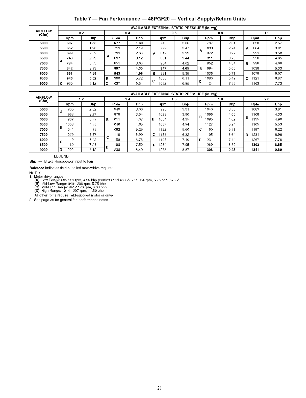
AIRFLOW
(Cfm)
5000
5500
6000
6500
7000
7500
8000
8500
9000
apm
607
652
699
746
A794
842
891
940
C 990
Table 7 -- Fan Performance -- 48PGF20 -- Vertical Supply/Return Units
0,2
Bhp
1.53
1,90
2.32
2.79
3.33
3.93
4,59
5,32
6.12
apm
677
719
763
807
851
897
943
990
1037
AVAILABLE EXTERNAL STATIC PRESSURE
0,4
Bhp
1.80
2.19
2.63
3.12
3.68
4.30
4.98 B
5.72 C
6.54
0,6
Rpm Bhp
740 2.06
779 2.47 A
A 819 2.93
861 3.44
904 4.02
947 4.65 B
991 5.35
1036 6.11 C
1082 6.95
(in. wg)
0.8
Rpm
797
833
872
911
952
994
1036
1080
1124
Bhp
2.31
2.74 A
3.22
3,75
4.34 B
5.00
5.71
6.49 C
7.35
1.0
Rpm Bhp
850 2.57
884 3.01
921 3.50
958 4.05
998 4.66
1038 5.33
1079 6.07
1121 6.87
1163 7.73
AIRFLOW
(Cfm)
5000
5500
6000
6500
7000
7500
8000
8500
9000
A
1003
B1041
1079
1119
C1160
D 1202
1,2
Rpm
900
933
967
Bhp
2.82
3.27
3.79
4.35
4.98
5.67
6.42
7.23
8.12
Rpm
949
979
B 1011
1046
1082
1119
C1158
1198
D1238
AVAILABLE EXTERNAL STATIC PRESSURE
1,4
Bhp
3.06
3.54
4.07 B 1054
4.65 1087
5.29 1122
5.99 C 1158
6.76 1195
7.59 D 1234
8.49 1273
1,6
Rpm Bhp
995 3.31
1023 3.80 B
4.35
4.94
5,60 C
6.32
7.10 D
7.95
8.87
(in, wg)
1.8
Rpm
1040
1066
1095
1127
1160
1195
1231
1269
1308
Bhp
3.56
4.06 B
4.62
5.24
5.91
6.64 D
7.44
8.30
9.23
2.0
Rpm
1083
1108
1135
1165
1197
1231
1267
1303
1341
Bhp
3.81
4.33
4.90
5.53
6.22
6.96
7.78
8.65
9.60
LEGEND
Bhp -- Brake Horsepower Input to Fan
Boldface indicates field-supplied motor/drive required.
NOTES:
1. Motor drive ranges:
(A) Low Range: 685-939 rpm, 4.26 bhp (208/230 and 460-v), 751-954 rpm, 5.75 bhp (575-v)
(B) Mid-Low Range: 949-1206 rpm, 5.75 bhp
(C) Mid-High Range: 941-1176 rpm, 8.63 bhp
(D) High Range: 1014-1297 rpm, 11.50 bhp
All other rpms require field-supplied motor or drive,
2. See page 36 for general fan performance notes.
2]
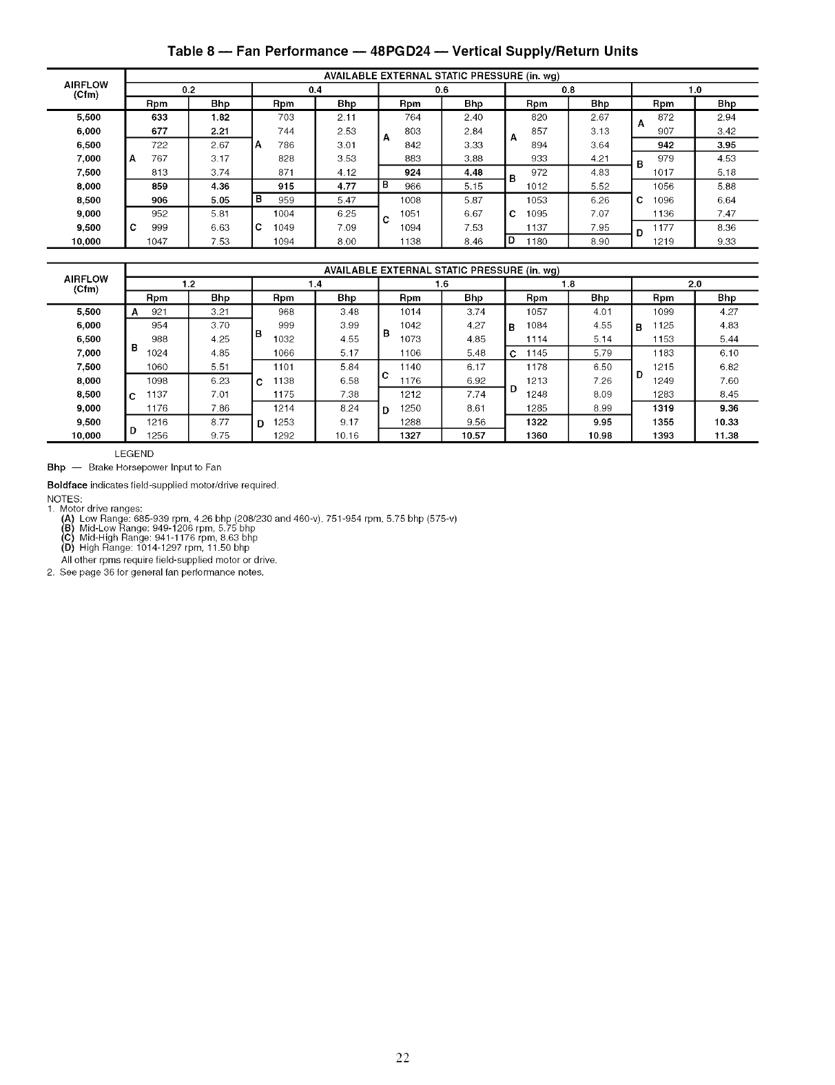
Table 8 -- Fan Performance -- 48PGD24 -- Vertical Supply/Return Units
PRESSURE (in. wg)
AIRFLOW
(Cfm)
5,500
6,000
6,500
7,000
7,500
8,000
8,500
9,000
9,500
10,000
Rpm
633
677
722
767
813
859
906
952
999
1047
0,2
Bhp
1.82
2.21
2.67
3.17
3.74
4,36
5.05
5.81
6.63
7.53
Rpm
7O3
744
A786
828
871
915
B959
1004
C 1049
1094
AVAILABLE EXTERNAL STATIC
0.4
Bhp Rpm
2.11 764
2.53 803
A
3.01 842
3.53 883
4.12 924
4,77 B 966
5.47 1008
6.25 1051
C
7.09 1094
8.00 1138
0.6
Bhp Rpm
2.40 820
2.64 857
A
3.33 894
3.86 933
4,48 972
B
5.15 1012
5.87 1053
6.67 C 1095
7.53 1137
8.46 D 1180
0.8
Bhp
2.67
3.13
3.64
4.21
4.83
5.52
6.26
7,07
7,95
8.90
A
942
979
B1017
1056
C 1096
1136
1177
D1219
1.0
Rpm
872
907
Bhp
2.94
3.42
3,95
4.53
5.18
5.88
6.64
7.47
8.36
9.33
PRESSURE (in. wg)
AIRFLOW
(Cfm) 2.0
5,500
6,000
6,500
7,000
7,500
8,000
8,500
9,000
9,500
10,000
Rpm
A 921
954
988
B1024
1060
1096
C 1137
1176
1216
D 1256
1,2
Bhp
3.21
3.70
4.25
4.85
5.51
6.23
7.01
7.66
8.77
9,75
Rpm
968
999
B1032
1066
1101
C 1136
1175
1214
D 1253
1292
AVAILABLE EXTERNAL STATIC
1.4
Bhp Rpm
3.48 1014
3.99 1042
B
4.55 1073
5.17 1106
5.84 1140
C
6.58 1176
7.36 1212
8.24 D 1250
9.17 1286
10.16 1327
1.6
Bhp Rpm
3.74 1057
4.27 B 1084
4.85 1114
5.48 C 1145
6.17 1178
6.92 1213
D
7.74 1248
8.61 1285
9.56 1322
16.57 1360
1.8
Bhp
4.01
4.55
5.14
5.79
6.50
7.26
6.09
8.99
9,95
10.98
Rpm
1099
B 1125
1153
1183
1215
D1249
1283
1319
1355
1393
Bhp
4.27
4.83
5.44
6.10
6.82
7.60
8.45
9.36
10,33
11,38
LEGEND
Bhp -- Brake Horsepower Inputto Fan
Boldface indicates field-supplied motor/drive required.
NOTES:
1. Motor drive ranges:
(A) Low Range: 685-939 rpm, 4.26 bhp (208/230 and 460-v), 751-954 rpm, 5.75 bhp (575-v)
(B) Mid-Low Range: 949-1206 rpm, 5.75 bhp
(C) Mid-High Range: 941-1176 rpm, 8.63 bhp
(D) High Range: 1014-1297 rpm, 11.50 bhp
All other rpms require field-supplied motor or drive.
2. See page 36 for general fan performance notes.
22
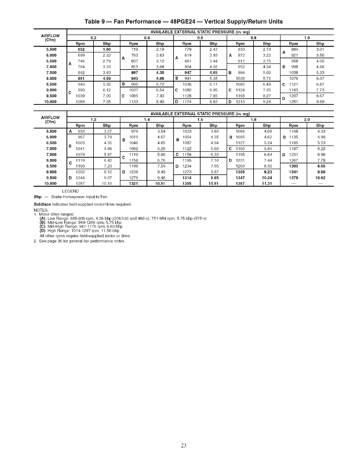
Table 9 -- Fan Performance -- 48PGE24 -- Vertical Supply/Return Units
AVAILABLE EXTERNAL STATIC PRESSURE
AIRFLOW
(Cfm) 0,2
5,500
6,000
6,500
7,000
7,500
8,000
8,500
9,000
9,500
10,000
apm
652
699
746
794
842
891
940
990
1039
1089
Bhp
1.90
2.32
2.79
3.33
3.93
4,59
5.32 B
6.12
7.00 C
7.95
apm
719
763
A8O7
851
897
943
990
1037
1085
1133
0,4
Bhp
2.19
2,63 A
3,12
3,68
4.30
4.98 B
5.72
6.54 C
7.43
8.40 D
0.6
Rpm Bhp
779 2.47
819 2,93 A
861 3.44
904 4.02
947 4.65 B
991 5.35
1036 6,11
1082 6,95 C
1128 7.85
1174 8.83 D
(in. wg)
0.8
Rpm
833
872
911
952
994
1036
1080
1124
1168
1213
Bhp
2.74 A
3.22
3.75
4.34 B
5.00
5.71
6.49 C
7.35
8.27 D
9.26
1.0
Rpm Bhp
884 3.01
921 3.50
958 4.05
998 4.66
1038 5.33
1079 6.07
1121 6.87
1163 7.73
1207 8.67
1251 9.69
AVAILABLE EXTERNAL STATIC PRESSURE
AIRFLOW 1,2
(Cfm)
5,500
6,000
6,500
7,000
7,500
8,000
8,500
9,000
9,500
10,000
A
B
C
D
Rpm
933
967
1003
1041
1079
1119
1160
1202
1244
1287
Bhp Rpm
3.27 979
3.79 1011
B
4.35 1046
4.98 1082
5.67 1119
C
6.42 1158
7.23 1198
8.12 D 1238
9.07 1279
10.10 1321
1.4
Bhp
3.54
4.07 1054
B
4.65 1087
5.29 1122
5.99 C 1158
6.76 1195
7.59 D 1234
8.49 1273
9.45 1314
10,51 1355
1,6
Rpm Bhp
1023 3.80
4.35 B
4.94
5.60 C
6.32
7.10 D
7.95
8.87
9.85
10.91
(in. wg)
1.8
Rpm
1056
1095
1127
1160
1195
1231
1269
1308
1347
1387
Bhp
4.06
4.62
5.24
5.91
6.64
7.44
8.30
9.23
10,24
11,31
Rpm
1108
B1135
1165
1197
D1231
1267
1303
1341
1379
2.0
Bhp
4.33
4.90
5.53
6.22
6.96
7.78
8,65
9.60
10.62
LEGEND
Bhp -- Brake Horsepower Inputto Fan
Boldface indicates field-supplied motor/drive required.
NOTES:
1. Motor drive ranges:
(A) Low Range: 685-939 rpm, 4.26 bhp (208/230 and 450-v), 751-954 rpm, 5.75 bhp (575-v)
(B) Mid-Low Range: 949-1206 rpm, 5.75 bhp
(C) Mid-High Range: 941-1176 rpm, 8.63 bhp
(D) High Range: 1014-1297 rpm, 11.50 bhp
All other rpms require field-supplied motor or drive.
2. Bee page 36 for general fan performance notes.
23
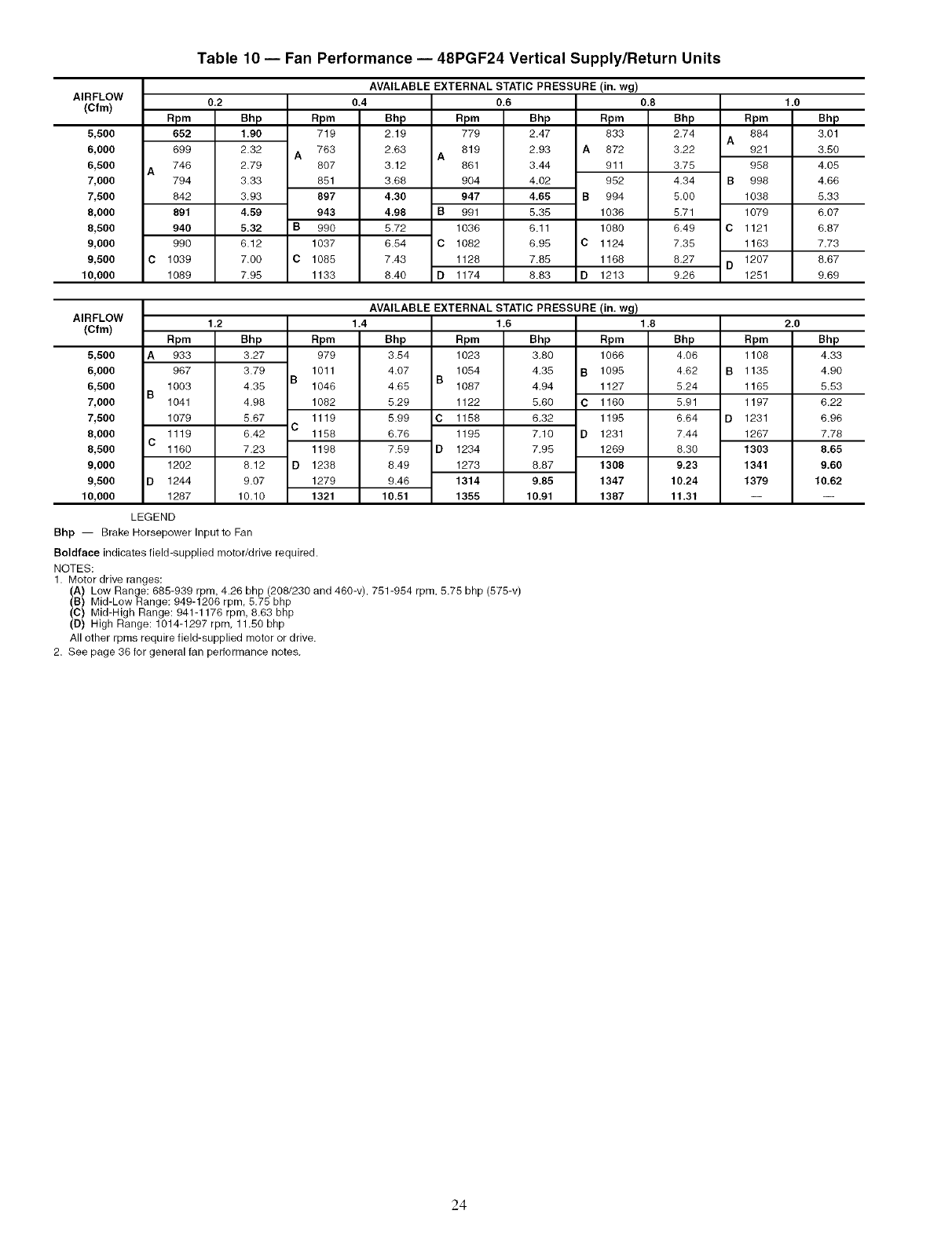
Table 10 -- Fan Performance -- 48PGF24 Vertical Supply/Return Units
PRESSURE (in. wg)
AIRFLOW
(Cfm) 0,2
5,500
6,000
6,500
7,000
7,500
8,000
8,500
9,000
9,500
10,000
Rpm
652
699
746
794
842
891
940
996
1039
1089
Bhp
1.90
2.32
2.79
3.33
3.93
4,59
5.32 B
6.12
7.00 C
7.95
Rpm
719
763
A8O7
851
897
943
990
1037
1085
1133
AVAILABLE EXTERNAL STATIC
0.4
Bhp Rpm
2.19 779
2.63 819
A
3.12 861
3.68 904
4.30 947
4,98 B 991
5.72 1036
6.54 C 1082
7.43 1126
8.40 D 1174
0.6
Bhp Rpm
2.47 833
2.93 A 872
3.44 911
4.02 952
4,65 B 994
5.35 1036
6.11 1080
6.95 C 1124
7.85 1168
8.63 D 1213
0.8
Bhp
2.74
3.22
3.75
4.34
5.00
5.71
6,49
7,35
8,27
9,26
apm
884
A921
958
B998
1038
1079
C 1121
1163
1207
D1251
1.0
Bhp
3.01
3.50
4.05
4.66
5.33
6.07
6.87
7.73
8.67
9.69
PRESSURE (in. wg)
AIRFLOW 1,2 2.0
(Cfm)
5,500
6,000
6,500
7,000
7,500
8,000
8,500
9,000
9,500
10,000
A
B
C
D
Rpm
933
967
1003
1041
1079
1119
1160
1202
1244
1287
Bhp Rpm
3.27 979
3.79 1011
B
4.35 1046
4.98 1082
5.67 1119
C
6.42 1158
7.23 1198
8.12 D 1236
9.07 1279
10,10 1321
AVAILABLE EXTERNAL STATIC
1.4
Bhp Rpm
3.54 1023
4.07 1054
B
4.65 1087
5.29 1122
5.99 C 1158
6.76 1195
7.59 D 1234
8.49 1273
9.46 1314
10.51 1355
1.6
Bhp Rpm
3.80 1066
4.35 B 1095
4.94 1127
5.60 C1160
6,32 1195
7.10 D 1231
7,95 1269
8,87 1306
9.85 1347
10.91 1387
1.8
Bhp
4.06
4.62
5.24
5.91
6.64
7.44
6.30
9,23
10.24
11.31
Rpm
1108
B 1135
1165
1197
D 1231
1267
1303
1341
1379
Bhp
4.33
4.90
5.53
6.22
6.96
7.78
8,65
9.60
10,62
LEGEND
Bhp -- Brake Horsepower Inputto Fan
Boldface indicates field-supplied motor/drive required.
NOTES:
1. Motor drive ranges:
(A) Low Range: 685-939 rpm, 4.26 bhp (208/230 and 460-v), 751-954 rpm, 5.75 bhp (575-v)
(B) Mid-Low Range: 949-1206 rpm, 5.75 bhp
(C) Mid-High Range: 941-1176 rpm, 8.63 bhp
(D) High Range: 1014-1297 rpm, 11.50 bhp
All other rpms require field-supplied motor or drive.
2. See page 36 for general fan performance notes,
24
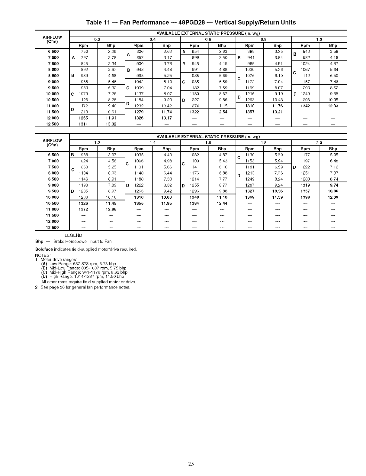
Table 11 -- Fan Performance- 48PGD28- Vertical Supply/Return Units
AVAILABLE EXTERNAL STATIC PRESSURE
AIRFLOW
(Cfm) 0,2
A
B
C
D
6,500
7,000
7,500
8,000
8,500
9,000
9,500
10,000
10,500
11,000
11,500
12,000
12,500
Rpm
750
797
845
892
939
986
1033
1079
1126
1172
1219
1265
1311
Bhp
2.28
2.78
3.34
3.97
4.68
5.46
6.32 C
7.26
8.28 D
9.40
10.61
11,91
13,32
apm
8O6
A853
9OO
B 948
995
1042
1090
1137
1184
1232
1279
1326
0,4
Bhp
2.62
3.17
3.78 B
4.48
5.25
6,10 C
7.04
8.07
9,20 D
10.42
11.74
13,17
0.6
Rpm Bhp
A854 2.93
899 3.50 B
945 4.15
991 4.88
1038 5.69 C
1085 6.59
1132 7.59
1180 8.67 D
1227 9.86
1274 11.15
1322 12.54
(in. wg)
0.8
Rpm
898
941
985
1030
1076
1122
1169
1216
1263
1310
1357
Bhp
3.25 B
3.84
4.51
5,26 C
6,10
7.04
8.07
9,19 D
10.43
11,76
13.21
1.0
Rpm
943
982
1024
1067
1112
1157
1203
1249
1296
1342
Bhp
3.59
4.18
4.87
5.64
6.50
7.46
8.52
9.68
10.95
12.33
AIRFLOW 1,2
(Cfm) Bhp Rpm
6,500
7,000
7,500
8,000
8,500
9,000
9,500
10,000
10,500
11,000
11,500
12,000
12,500
B
C
Rpm
988
1024
1063
1104
1146
1190
1235
1280
1326
1372
3.97 1035
4.56 1066
C
5.25 1101
6.03 1140
6.91 1180
7.89 D 1222
8.97 1266
AVAILABLE EXTERNAL STATIC PRESSURE
1.4 1,6
Bhp Rpm Bhp
4.40 1082 4.87 C
4.98 1109 5.43
C
5.66 1141 6.10
6.44 1176 6.88 D
7.33 1214 7.77
8.32 D 1255 8.77
9.42 1296 9.88
10.63 1340 11.10
11,95 1384 12.44
10.16
11.45
12,86
1310
1355
(in, wg)
1,8
Rpm
1130
1153
1181
1213
1249
1287
1327
1369
Bhp
5,39
5,94
6,59 D
7,36
8,24
9,24
10,36
11.59
LEGEND
Bhp -- Brake Horsepower Inputto Fan
Boldface indicates field-supplied motor/drive required.
NOTES:
1. Motor drive ranges:
(A) Low Range: 687-873 rpm, 5.75 bhp
(B) Mid-Low Range: 805-1007 rpm, 5.75 bhp
(C) Mid-High Range: 941-1176 rpm, 8.63 bhp
(D) High Range: 1014-1297 rpm, 11.50 bhp
All other rpms require field-supplied motor or drive.
2. See page 36 for general fan performance notes.
2.0
Rpm Bhp
1177 5.95
1197 6.48
1222 7.12
1251 7.87
1283 8.74
1319 9,74
1357 10.86
1398 12.09
2.5
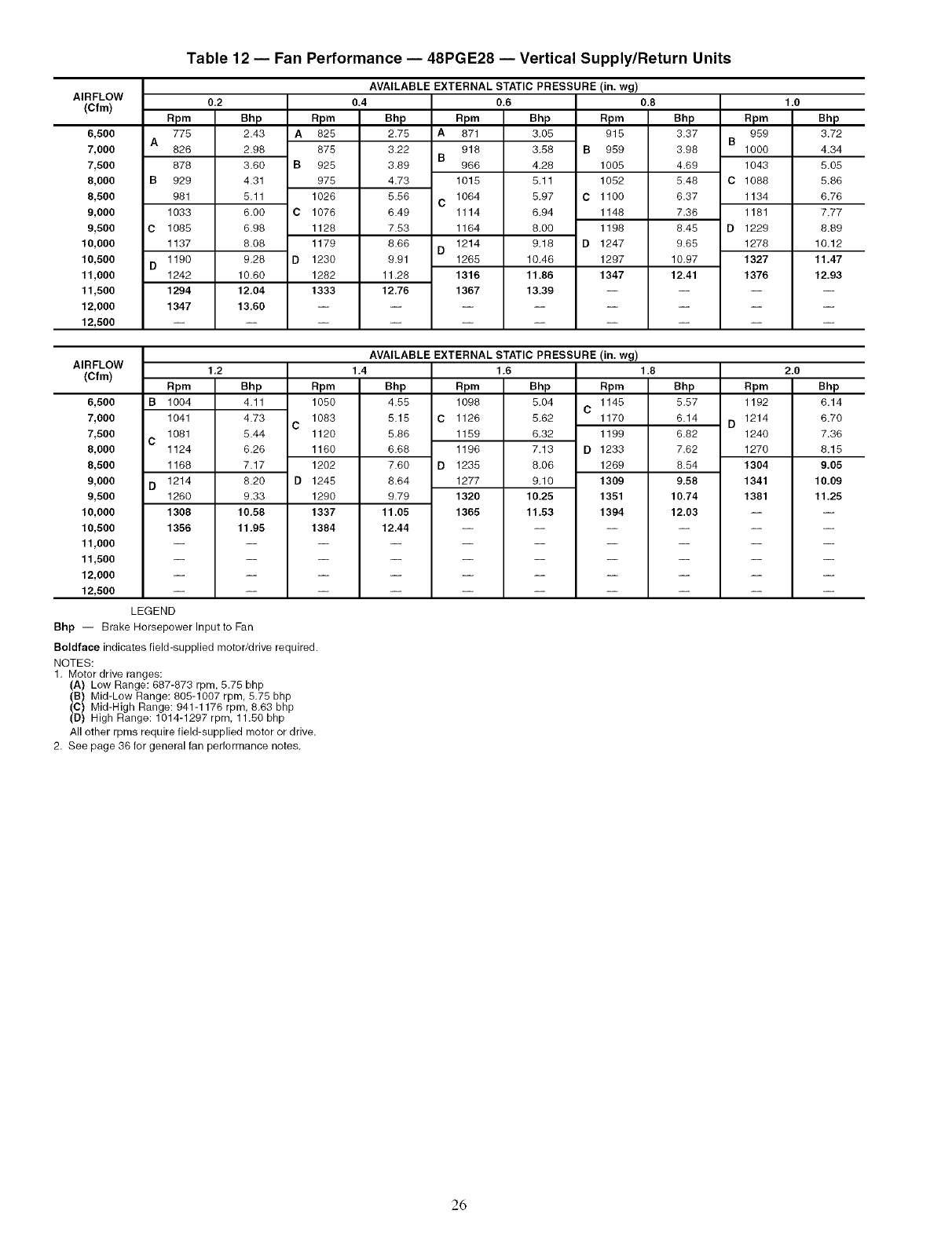
Table 12 -- Fan Performance -- 48PGE28 -- Vertical Supply/Return Units
AVAILABLE EXTERNAL STATIC PRESSURE (in. wg)
AIRFLOW
(Cfm) 0,2
A
B
C
D
6,500
7,000
7,500
8,000
8,500
9,000
9,500
10,000
10,500
11,000
11,500
12,000
12,500
Rpm
776
826
878
929
981
1033
1085
1137
1190
1242
1294
1347
Bhp
2.43
2.98
3.60
4.31
5.11
6.00 C
6.98
8.08
9.28 D
10.60
12.04
13,60
Rpm
A825
875
B 925
975
1026
1076
1128
1179
1230
1282
1333
0.4
Bhp
2.75 A
3.22 B
3.89
4.73
5.56 C
6.49
7.53
8.66 D
9.91
11.28
12.76
0.6
Rpm Bhp Rpm
871 3.05 915
918 3.58 B 959
966 4.28 1005
1015 5.11 1052
1064 5.97 C 1100
1114 6.94 1148
1164 8.00 1198
1214 9.18 D1247
1265 10.46 1297
1316 11.86 1347
1367 13.39 --
0.8
Bhp
3.37
3.98
4.69
5.48
6.37
7.36
8.45
9.65
10.97
12.41
AVAILABLE EXTERNAL STATIC PRESSURE (in. wg)
AIRFLOW 1,2
(Cfm)
6,500
7,000
7,500
8,000
8,500
9,000
9,500
10,000
10,500
11,000
11,500
12,000
12,500
B
C
D
Rpm
1004
1041
1081
1124
1168
1214
1260
1308
1356
5.44
6.26
7.17
8.20
9.33
10,58
11.95
Bhp Rpm
4.11 1050
4.73 1083
C1120
1160
1202
D 1245
1290
1337
1384
1.4
Bhp
4.55
5.15 C
5.86
6.68
7.60 D
8.64
9.79
11.05
12.44
1.6
Rpm Bhp Rpm
1096 5.04 1145
C
1126 5.62 1170
1159 6.32 1199
1196 7.13 D 1233
1235 8.06 1269
1277 9.10 1309
1320 10.26 1351
1365 11.53 1394
1.8
Bhp
5.57
6.14
6.82
7.62
8.54
9,58
10.74
12.03
LEGEND
Bhp -- Brake Horsepower Inputto Fan
Boldface indicates field-supplied motor/drive required.
NOTES:
1. Motor drive ranges:
(A) Low Range: 687-873 rpm. 5.75 bhp
(B) Mid-Low Range: 805-1007 rpm, 5.75 bhp
(C) Mid-High Range: 941-1176 rpm, 8.63 bhp
(D) High Range: 1014-1297 rpm, 11.50 bhp
All other rpms require field-supplied motor or drive.
2. See page 36 for general fan performance notes.
1.0
Rpm Bhp
959 3.72
B1000 4.34
1043 5.05
C 1088 5.86
1134 6.76
1181 7.77
D 1229 8.89
1278 10.12
1327 11,47
1376 12.93
2.0
Rpm Bhp
1192 6.14
1214 6.70
D1240 7.36
1270 8.15
1304 9,05
1341 10,09
1381 11,25
26
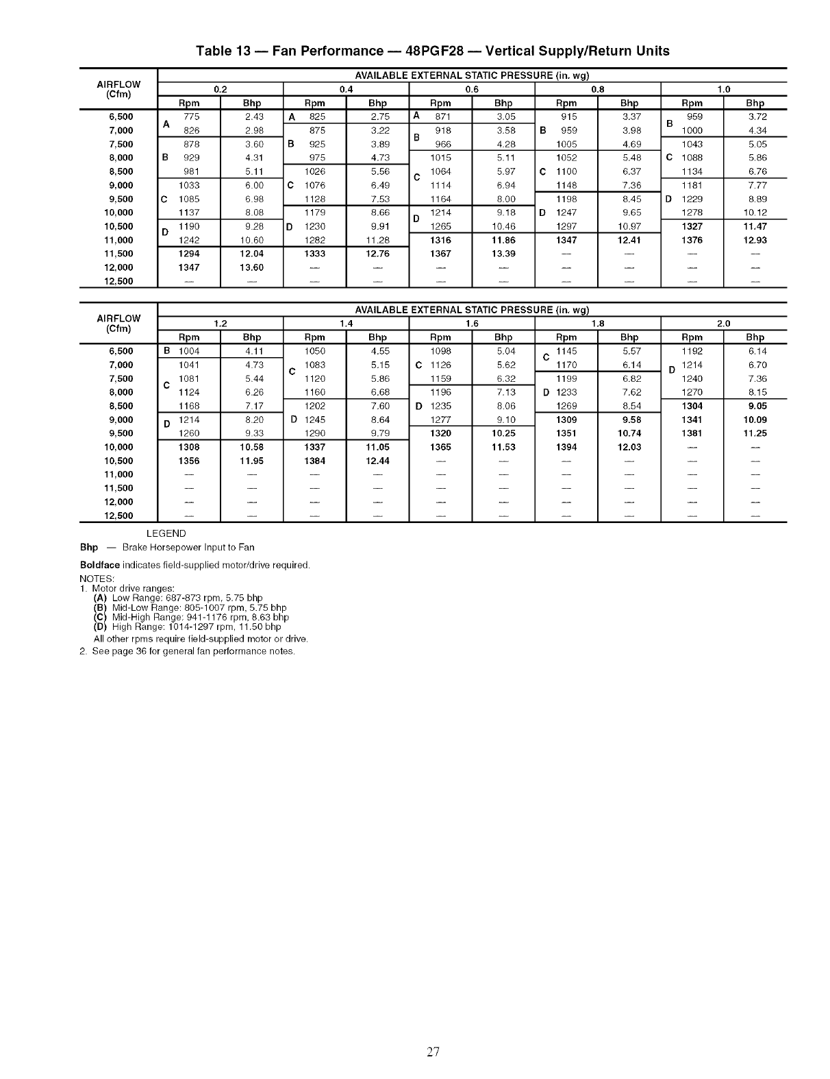
Table 13 -- Fan Performance -- 48PGF28 -- Vertical Supply/Return Units
AVAILABLE EXTERNAL STATIC PRESSURE
AIRFLOW
(Cfm)
A
B
C
D
6,500
7,000
7,500
8,000
8,500
9,000
9,500
10,000
10,500
11,000
11,500
12,000
12,500
apm
775
826
878
929
981
1033
1085
1137
1190
1242
1294
1347
0,2
Bhp
2.43
2.98
3.60
4.31
5.11
6.00 C
6.98
8.08
9.28 D
10.60
12.04
13,60
apm
A825
875
B 925
975
1026
1076
1128
1179
1230
1282
1333
0,4
Bhp
2.75 A
3.22 B
3.89
4.73
5.56 C
6.49
7.53
8.66 D
9.91
11.28
12.76
0.6
Rpm Bhp
871 3.05
918 3.58 B
966 4.28
1015 5.11
1064 5.97 C
1114 6.94
1164 8.00
1214 9.18 D
1265 10.46
1316 11.86
1367 13.39
(in. wg)
0.8
Rpm
915
959
1005
1052
1100
1148
1198
1247
1297
1347
Bhp
3,37
3,98
4,69
5.48
6,37
7,36
8.45
9,65
10.97
12.41
B
C
D
AVAILABLE EXTERNAL STATIC PRESSURE
AIRFLOW 1,2
(Cfm)
6,500
7,000
7,500
8,000
8,500
9,000
9,500
10,000
10,500
11,000
11,500
12,000
12,500
B
C
D
Rpm
1004
1041
1081
1124
1168
1214
1260
1308
1356
Bhp Rpm
4.11 1050
4.73 1083
C
5.44 1120
6.26 1160
7.17 1202
8.20 D 1245
9.33 1290
10,58 1337
11.95 1384
1.4
Bhp Rpm
4.55 1098
5.15 C 1126
5.86 1159
6.68 1196
7.60 D 1235
8.64 1277
9.79 1320
11,05 1365
12,44
1,6
Bhp
5.04 C
5.62
6.32
7.13 D
8.06
9.10
10.25
11.53
(in, wg)
1,8
Rpm
1145
1170
1199
1233
1269
1309
1351
1394
Bhp
5.57
6.14
6.82
7.62
8.54
9.58
10.74
12.03
LEGEND
Bhp -- Brake Horsepower Inputto Fan
Boldface indicates field-supplied motor/drive required.
NOTES:
1. Motor drive ranges:
(A) Low Range: 687-873 rpm, 5.75 bhp
(B) Mid-Low Range: 805-1007 rpm, 5.75 bhp
(C) Mid-High Range: 941-1176 rpm, 8.63 bhp
(D) High Range: 1014-1297 rpm, 11.50 bhp
All other rpms require field-supplied motor or drive.
2. See page 36 for general fan performance notes.
1.0
Rpm Bhp
959 3,72
1000 4.34
1043 5.05
1088 5.86
1134 6.76
1181 7.77
1229 8.89
1278 10.12
1327 11,47
1376 12,93
2.0
Rpm Bhp
1192 6.14
D 1214 6.70
1240 7.36
1270 8.15
1304 9,05
1341 10,09
1381 11,25
27
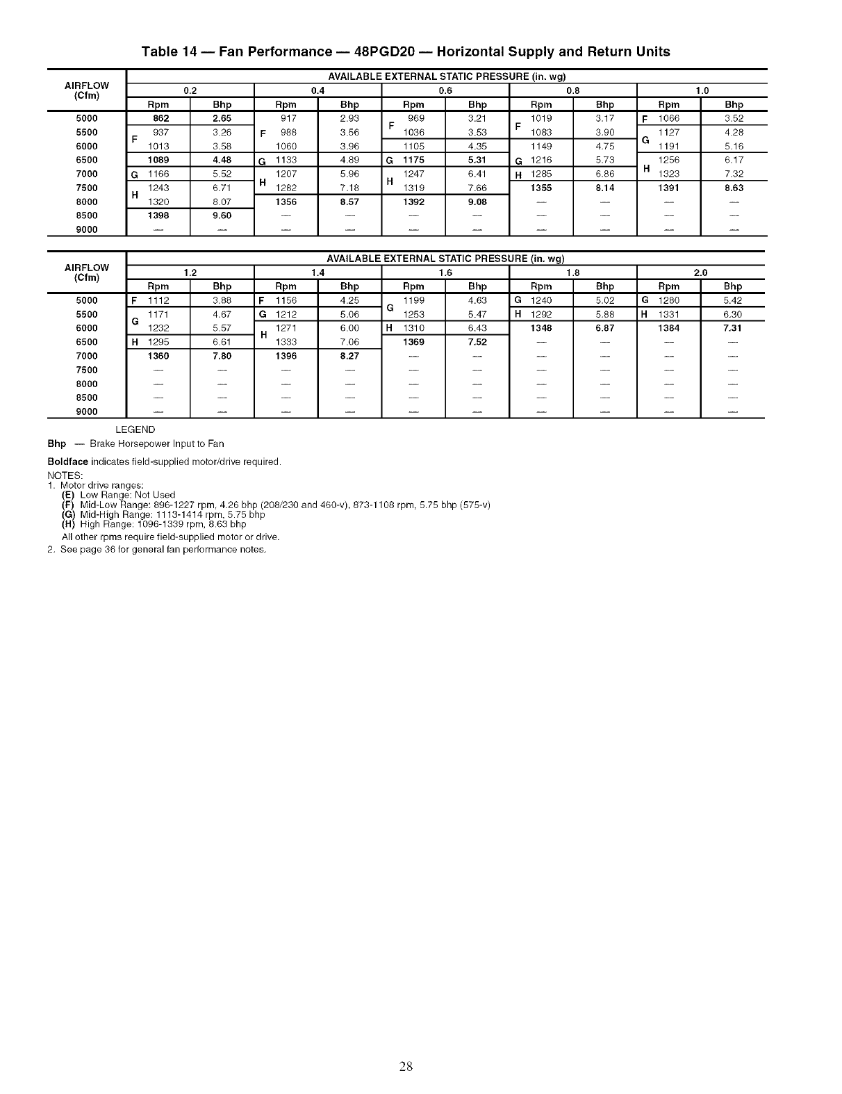
AIRFLOW
(Cfm)
5000
5500
6000
6500
7000
7500
8000
8500
9000
F
G
H
Table 14 -- Fan Performance- 48PGD20 -- Horizontal Supply and Return Units
Rpm
862
937
1013
1089
1166
1243
1320
1398
0,2
Bhp
2.65
3.26
3.58
4.48
5.52
6.71
8.07
9,60
Rpm
917
F988
1060
G 1133
1207
H1282
1356
AVAILABLE EXTERNAL STATIC PRESSURE (in. wg)
0.8 1.O0.4
Bhp
2.93 F
3.56
3.96
4.89 G
5.96 R
7.18
8.57
Rpm
969
1036
1105
1175
1247
1319
1392
0.6
Bhp
3.21
3.53
4.35
5,31
6.41
7.66
9.08
apm
1019
F1083
1149
G 1216
R 1285
1355
Bhp Rpm
3.17 F1066
3.90 1127
G
4.75 1191
5.73 1256
H
6.86 1323
8.14 1391
Bhp
3.52
4.28
5.16
6.17
7.32
8,63
AIRFLOW
(Cfm)
5000
5500
6000
6500
7000
7500
8000
8500
9000
Rpm
F 1112
1171
G1232
H 1295
1360
1.2
Bhp
3.88
4.67
Rpm
F 1156
G 1212
AVAILABLE EXTERNAL STATIC PRESSURE (in. wg)
1.4 1,6 1.8
Bhp Rpm Bhp Rpm
4.25 1199 4.63 G 1240
G
5.06 1253 5.47 H 1292
1310
1369
6.43 1348
7,52
Bhp Rpm
5.02 G 1280
5.88 H 1331
6.87 13845.57 H
6.61
7,80
1271
1333
1396
6.00 H
7.06
8,27
2.0
Bhp
5.42
6,30
7,31
LEGEND
Bhp -- Brake Horsepower Inputto Fan
Boldface indicates field-supplied motor/drive required.
NOTES:
1. Motor drive ranges:
(E) Low Range: Net Used
(F) Mid-Low Range: 896-1227 rpm, 4.26 bhp (208/230 and 460-v), 873-1108 rpm, 5.75 bhp (575-v)
(G) Mid-High Range: 1113-1414 rpm, 5.75 bhp
(H) High Range: 1096-1339 rpm, 8.63 bhp
All other rpms require field-supplied motor or drive,
2. See page 36 for general fan performance notes.
28
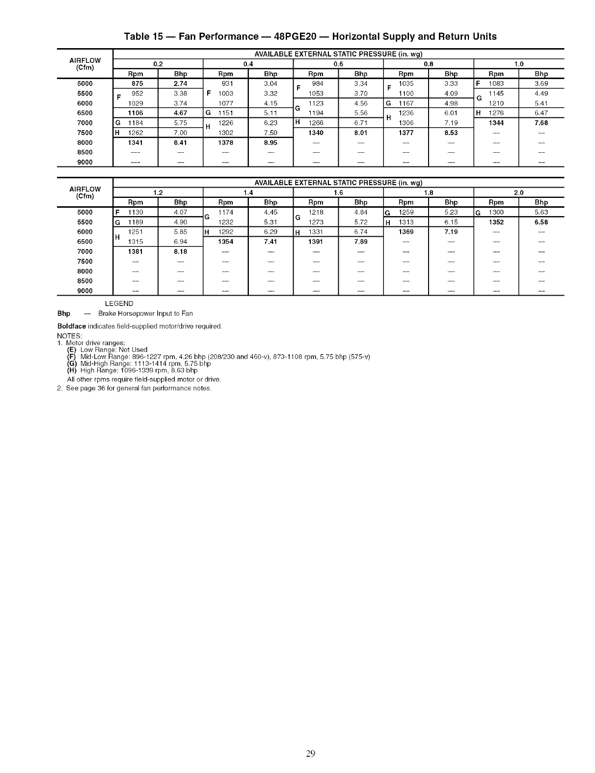
AIRFLOW
(Cfm)
5000
5500
6000
6500
7000
7500
8000
8500
9000
Table 15 -- Fan Performance- 48PGE20 -- Horizontal Supply and Return Units
F
G
H
apm
875
952
1029
1106
1184
1262
1341
0,2
Bhp
2.74
3.38
3.74
4.67
5.75
7.00
8,41
apm
931
F1003
1077
G 1151
1226
H1302
1378
AVAILABLE EXTERNAL STATIC PRESSURE (in. wg)
0.80,4
Bhp
3.04 F
3.32
4.15 G
5.11
6.23 H
7,50
8.95
Rpm
984
1053
1123
1194
1266
1340
0.6
Bhp
3.34
3.70
4.56
5.56
6.71
8.01
Rpm
1035
F1100
G 1167
1236
H1306
1377
AVAILABLE EXTERNAL STATIC PRESSURE (in. wg)
Bhp
3.33 F
4.09 G
4.98
6.01 H
7.19
8,53
1.0
Rpm Bhp
1083 3.69
1145 4.49
1210 5.41
1276 6.47
1344 7.68
AIRFLOW
(Cfm)
5000
5500
6000
6500
7000
7500
8000
8500
9000
F
G
H
Rpm
1130
1189
1251
1315
1381
1,2
Bhp
4.07
4.90
5.85
6.94
8,18
Rpm
1174
G1232
H 1292
1354
1,4
Bhp
4.45 G
5.31
6.29 H
7.41
Rpm
1218
1273
1331
1391
1,6
Bhp
4.84
5.72
6.74
7.89
1.8
Rpm
1259
1313
1369
Bhp
5.23 G
6.15
7,19
2.0
Rpm Bhp
1300 5,63
1352 6.58
LEGEND
Bhp -- Brake Horsepower Input to Fan
Boldface indicates field-supplied motor/drive required.
NOTES:
1. Motor drive ranges:
(E) Low Range: Net Used
(F) Mid-Low Range: 896-1227 rpm, 4.26 bhp (208/230 and 460-v), 873-1108 rpm, 5.75 bhp (575-v)
(G) Mid-High Range: 1113-1414 rpm, 5.75 bhp
(H) High Range: 1096-1339 rpm, 8.63 bhp
All other rpms require field-supplied motor or drive,
2. See page 36 for general fan performance notes.
29
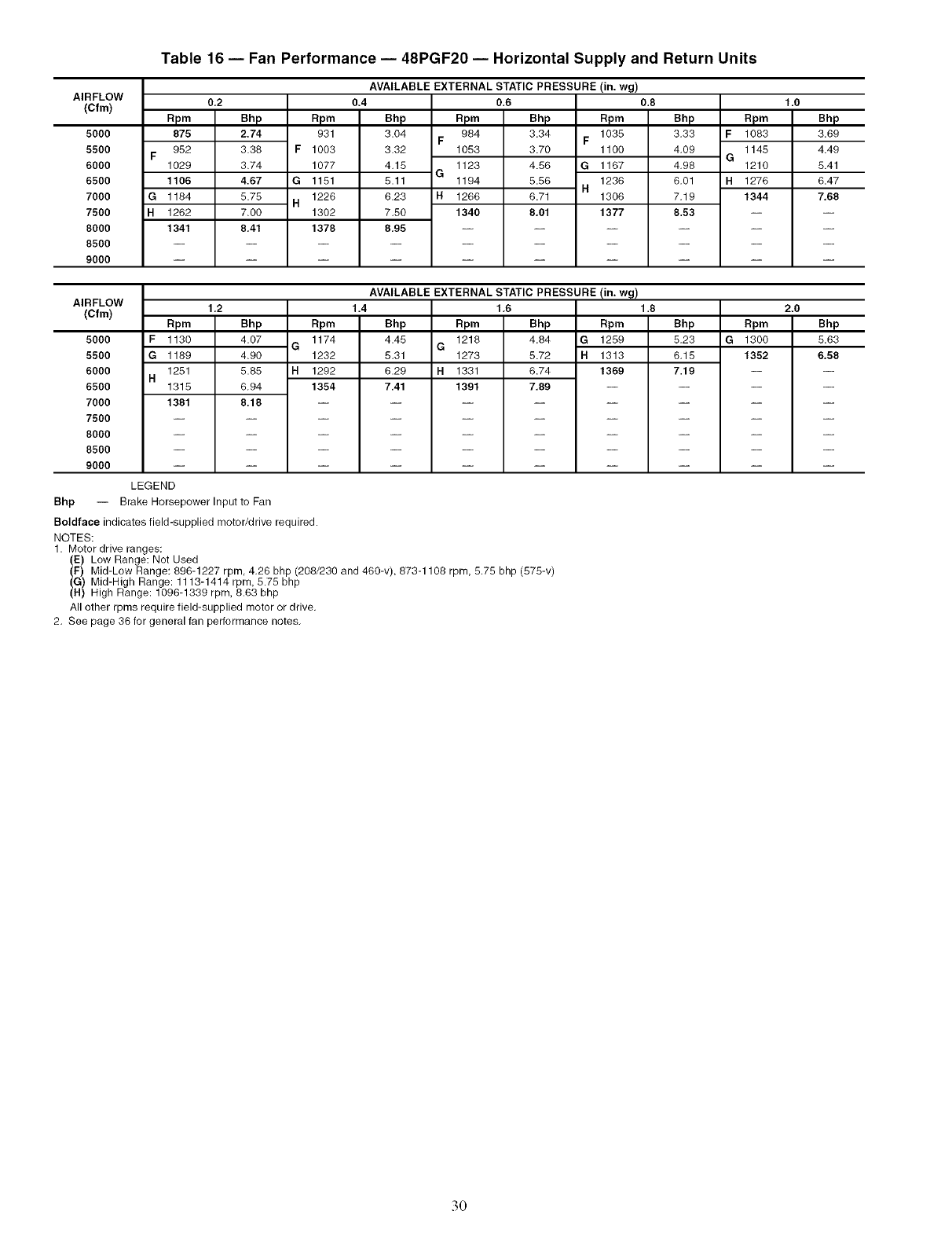
AIRFLOW
(Cfm)
5000
5500
6000
6500
7000
7500
8000
8500
9000
Table 16 -- Fan Performance -- 48PGF20 -- Horizontal Supply and Return Units
F
G
H
Rpm
875
952
1029
1106
1184
1262
1341
0,2
Bhp
2.74
3.38
3.74
4.67
5.75
7.00
8,41
Rpm
931
F 1003
1077
G 1151
1226
H1302
1378
AVAILABLE EXTERNAL STATIC PRESSURE (in. wg)
0.4
Bhp
3.04 F
3.32
4.15 G
5.11
6.23 H
7.50
8,95
0.6
Rpm Bhp Rpm
984 3.34 1035
F
1053 3.70 1100
1123 4.56 G 1167
1194 5.56 1236
H
1266 6.71 1306
1340 8,01 1377
0.8
Bhp
3.33
4.09
4.98
6,01
7.19
8.53
apm
F 1083
1145
G1210
H 1276
1344
1.0
Bhp
3.69
4.49
5.41
6.47
7,68
AIRFLOW
(Cfm)
5000
5500
6000
6500
7000
7500
8000
8500
9000
F
G
H
1.2
Rpm
1174
G1232
AVAILABLE EXTERNAL STATIC PRESSURE (in. wg)
1.4 1,6
Bhp Rpm Bhp Rpm
4.45 1218 4.84 G 1259
G
5.31 1273 5.72 H 1313
H 1331
1391
6.74
7.89
1369
1.8
Bhp
5.23
6.15
Rpm
G 1300
1352
Rpm
1130
1189
1251 5.85
1315 6,94
1381 8.18
Bhp
4.07
4.90
H 1292
1354
6.29
7,41
7.19
2.0
Bhp
5.63
6,58
LEGEND
Bhp -- Brake Horsepower Input to Fan
Boldface indicates field-supplied motor/drive required.
NOTES:
1. Motor drive ranges:
(E) Low Range: Not Used
(F) Mid-Low Range: 896-1227 rpm, 4.26 bhp (206/230 and 460-v), 673-1108 rpm, 5.75 bhp (575-v)
(G) Mid-High Range: 1113-1414 rpm, 5.75 bhp
(H) High Range: 1096-1339 rpm, 6.63 bhp
All other rpme require field-supplied motor or drive,
2. See page 36 for general fan performance notes.
3O
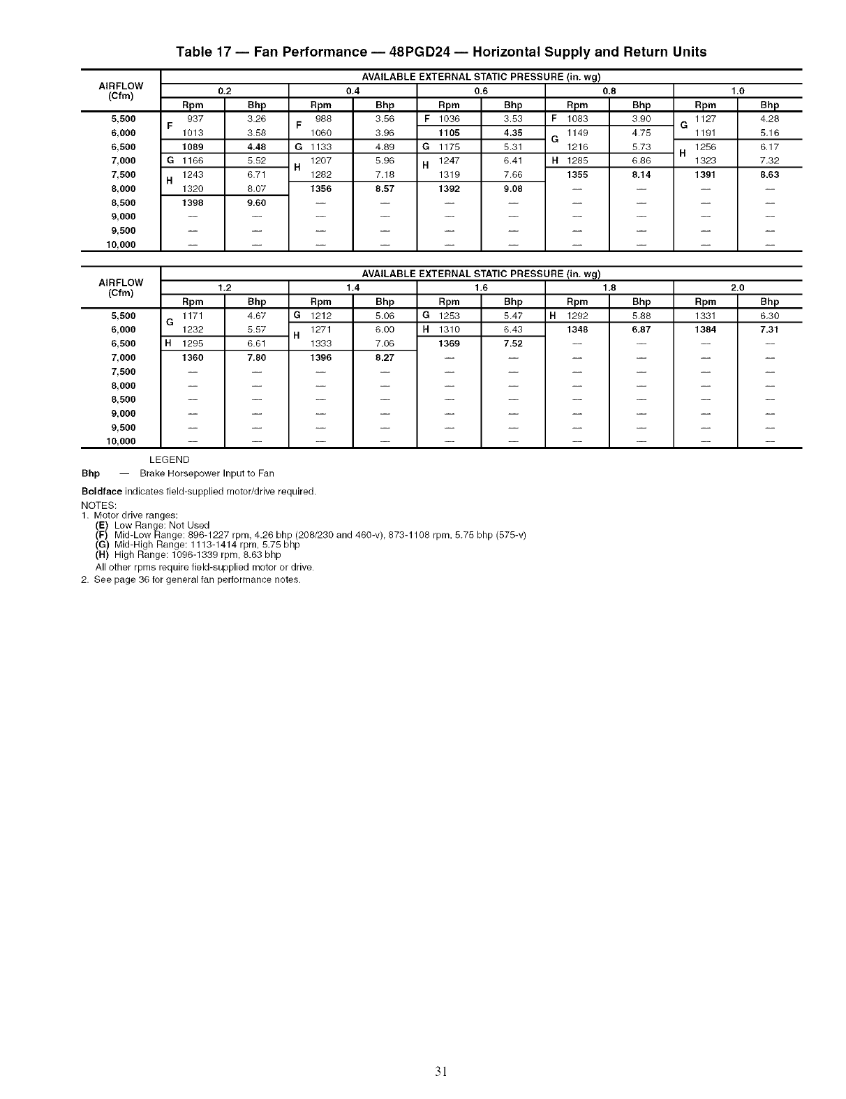
Table 17 -- Fan Performance -- 48PGD24 -- Horizontal Supply and Return Units
AVAILABLE EXTERNAL STATIC PRESSURE (in. wg)
AIRFLOW
(Cfm)
5,500
6,000
6,500
7,000
7,500
8,000
8,500
9,000
9,500
10,000
apm
937
F1013
1089
G 1166
1243
H1320
1398
0,2
Bhp
3.26
3.58
4,48
5.52
6.71
8.07
9,60
apm
988
F1060
G 1133
1207
H1282
1356
0,4
Bhp Rpm
3.56 F 1036
3.96 1105
4,89 G 1175
5.96 H 1247
7.18 1319
8.57 1392
0.6 0.8
Bhp Rpm
3.53 F 1083
4.35 1149
G
5,31 1216
6.41 H 1285
7,66 1355
9.08
AVAILABLE EXTERNAL STATIC PRESSURE (in, wg)
AIRFLOW 1,2 1.4 1,6 1,8
(Cfm)
Bhp
3.90 G
4.75
5.73 H
6.86
8,14
1.0
Rpm Bhp
1127 4.28
1191 5.16
1256 6,17
1323 7.32
1391 8.63
5,500
6,000
6,500
7,000
7,500
8,000
8,500
9,000
9,500
10,000
G
H
Rpm
1171
1232
1295
1360
Bhp
4.67
5.57
Rpm
G 1212
1271
H
Bhp
5.06
6.00
Bhp
5.47
6.43
Rpm
H1292
1348
6.61
7,80
1333
1396
Rpm
G 1253
H1310
7.06 1369
8.27
7.52
Bhp
5.88
6,87
Rpm
1331
1384
2.0
Bhp
6.30
7.31
LEGEND
Bhp -- Brake Horsepower Input to Fan
Boldface indicates field-supplied motor/drive required.
NOTES:
1. Motor drive ranges:
(E) Low Range: Net Used
(F) Mid-Low Range: 896-1227 rpm, 4.26 bhp (208/230 and 460-v), 873-1108 rpm, 5.75 bhp (575-v)
(G) Mid-High Range: 1113-1414 rpm, 5.75 bhp
(H) High Range: 1096-1339 rpm, 8.63 bhp
All other rpms require field-supplied motor or drive.
2. See page 36 for general fan performance notes.
3!
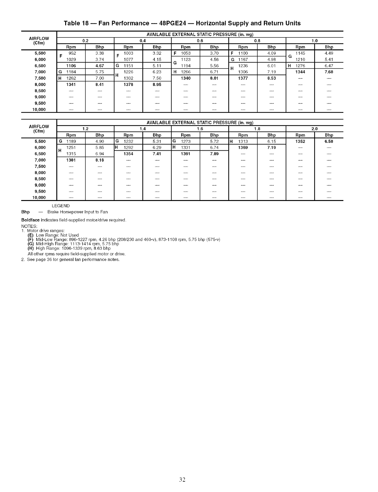
Table 18 -- Fan Performance -- 48PGE24 -- Horizontal Supply and Return Units
AVAILABLE EXTERNAL STATIC PRESSURE (in. wg)
AIRFLOW
(Cfm) 0,2
5,500
6,000
6,500
7,000
7,500
8,000
8,500
9,000
9,500
10,000
F
G
H
Rpm
952
1029
1106
1184
1262
1341
Bhp
3.38
3.74
4.67
5.75
7.00
8,41
Rpm
1003
F1077
G1151
1226
H1302
1378
0.4
Bhp
3.32 F
4.15 G
5.11
6.23 H
7.50
8,95
0.6
Rpm Bhp Rpm
1053 3.70 F 1100
1123 4.56 G 1167
1194 5.56 1236
H
1266 6.71 1306
1340 8,01 1377
AVAILABLE EXTERNAL STATIC PRESSURE (in. wg)
AIRFLOW
(Cfm)
0.8
Bhp
4,09
4,96
6,01
7,19
8.53
apm
1145
G1210
H1276
1344
1.0
Bhp
4.49
5.41
6.47
7.68
5,500
6,000
6,500
7,000
7,500
8,0OO
8,500
9,0OO
9,500
10,000
Bhp --
1,2
Rpm Bhp
G 1189 4.90
1251 5.85
H1315 6.94
1381 8.18
LEGEND
Bmke HorsepowerlnputtoFan
Rpm
G 1232
H1292
1354
1.4
Bhp
5.31 G
6.29 H
7,41
1.6
Rpm Bhp Rpm
1273 5.72 H1313
1331 6.74 1369
1391 7.89 --
1.8
Bhp
6,15
7.19
Rpm
1352
Boldface indicates field-supplied motor/drive required.
NOTES:
1. Motor drive ranges:
(E) Low Range: Net Used
(F) Mid-Low Range: 896-1227 rpm, 4,26 bhp (208/230 and 460-v), 873-1108 rpm, 5.75 bhp (575-v)
(G) Mid-High Range: 1113-1414 rpm, 5.75 bhp
(H) High Range: 1096-1339 rpm, 8.63 bhp
All other rpms require field-supplied motor or drive.
2. See page 36 for general fan performance notes.
2.0
Bhp
6,58
32
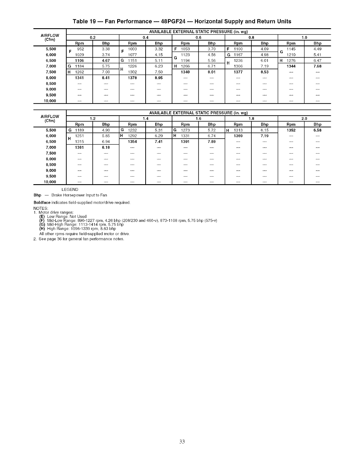
Table 19 -- Fan Performance -- 48PGF24 -- Horizontal Supply and Return Units
AVAILABLE EXTERNAL STATIC PRESSURE (in. wg)
AIRFLOW
(Cfm) 0,2 0.8
5,500
6,000
6,500
7,000
7,500
8,000
8,500
9,000
9,500
10,000
Rpm
952
F1029
1106
G1184
H1262
1341
Bhp
3.38
3.74
4,67
5.75 H
7.00
8,41
Rpm
1003
F1077
G1151
1228
1302
1378
0,4
Bhp
3.32 F
4.15 G
5.11
6.23 H
7,50
8.95
Rpm
1053
1123
1194
1266
1340
0.6
Bhp
3.70
4.56
5.56
6.71
8.01
Rpm
F1100
G 1167
1236
H1306
1377
Bhp
4.09 G
4.98
6.01 H
7.19
8.53
1.0
Rpm Bhp
1145 4.49
1210 5.41
1276 6.47
1344 7.68
AVAILABLE EXTERNAL STATIC PRESSURE (in, wg)
AIRFLOW 1,8
(Cfm)
5,500
6,000
6,500
7,000
7,500
8,000
8,500
9,000
9,500
10,000
Rpm
G 1189
1251
H1315
1381
LEGEND
1,2
Bhp
4.90
5.85
6.94
8,18
Rpm
G 1232
H1292
1354
1.4
Bhp
5.31 G
6.29 H
7.41
Rpm
1273
1331
1391
1,6
Bhp
5.72
6.74
7.89
Rpm
H1313
1369
Bhp
6.15
7,19
Bhp -- Brake Horsepower Inputto Fan
Boldface indicates field-supplied motor/drive required.
NOTES:
1. Motor drive ranges:
(E) Low Range: Not Used
(F) Mid-Low Range: 896-1227 rpm, 4.26 bhp (208/230 and 460-v), 873-1108 rpm, 5.75 bhp (575-v)
(G) Mid-High Range: 1113-1414 rpm, 5.75 bhp
(H) High Range: 1096-1339 rpm, 8.63 bhp
All other rpms require field-supplied motor or drive.
2. See page 36 for general fan performance notes.
2.0
Rpm Bhp
1352 6.58
33
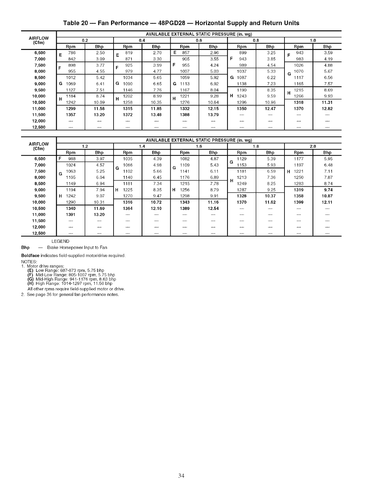
Table 20 -- Fan Performance -- 48PGD28 -- Horizontal Supply and Return Units
AVAILABLE EXTERNAL STATIC PRESSURE (in. wg)
AIRFLOW
(Cfm) 0,2 1.0
6,500
7,000
7,500
8,000
8,500
9,000
9,500
10,000
10,500
11,000
11,500
12,000
12,500
E
F
G
H
Rpm
788
842
898
965
1012
1069
1127
1184
1242
1299
1357
Bhp
2.50
3.09
3.77
4.55
5.42
6.41
7.51
8.74
10.09
11,58
13.20
Rpm
819
E871
925
F979
1034
G 1090
1146
1202
N1258
1315
1372
0.4
Bhp
2.70 E
3.30
3.99 F
4.77
5.65
6.65 G
7.76
8.99 H
10.35
11.85
13.48
0.6
Rpm Bhp Rpm
857 2.96 899
905 3.55 F 943
955 4.24 989
1007 5.03 1037
1059 5.92 G 1087
1113 6.92 1138
1167 8.04 1190
1221 9.28 N 1243
1276 10.64 1296
1332 12.15 1350
1388 13.79 --
0.8
Bhp
3.25
3.85
4.54
5.33
6.22
7.23
8.35
9.59
10.96
12.47
apm
943
F983
1026
1070
G1117
1165
1215
H1266
1318
1370
AVAILABLE EXTERNAL STATIC PRESSURE (in. wg)
AIRFLOW 1,2 1.8 2.0
(Cfm)
Bhp
3.59
4.19
4.88
5.67
6.56
7.57
8.69
9.93
11,31
12,82
6,500
7,000
7,500
8,000
8,500
9,000
9,500
10,000
10,500
11,000
11,500
12,000
12,500
F
G
Rpm
988
1024
1063
1105
1149
1194
Bhp Rpm
3.97 1035
4.57 1068
G
5.25 1102
8.04 1140
8.94 1181
7.94 H 1225
1.4
Bhp
4.39
4.98 G
5.66
6.45
7.34
8.35 H
1.6
Rpm Bhp Rpm
1082 4.87 1129
G
1109 5.43 1153
1141 8.11 1181
1176 6.89 1213
H
1215 7.78 1249
1256 8.79 1287
Bhp Rpm
5.39 1177
5.93 1197
6.69 H1221
7.36 1250
8.25 1283
9.25 1319
Bhp
5.95
6.48
7.11
7.87
8.74
9,74
1242 9,07
1290 10.31
1340 11.69
1391 13,20
1270
1316
1364
9.47 1298 9.91
10.72 1343 11.16
12.10 1389 12.54
1328
1370
10.37
11.62
1358
1399
10.87
12,11
LEGEND
Bhp -- Brake Horsepower Input to Fan
Boldface indicates field-supplied motor/drive required.
NOTES:
1. Motor drive ranges:
(E) Low Range: 887-873 rpm. 5.75 bhp
(F) Mid-Low Range: 805-1007 rpm, 5.75 bhp
(G) Mid-High Range: 941-1178 rpm, 8.63 bhp
(H) High Range: 1014-1297 rpm, 11.50 bhp
All other rpms require field-supplied motor or drive.
2. See page 36 for general fan performance notes.
34
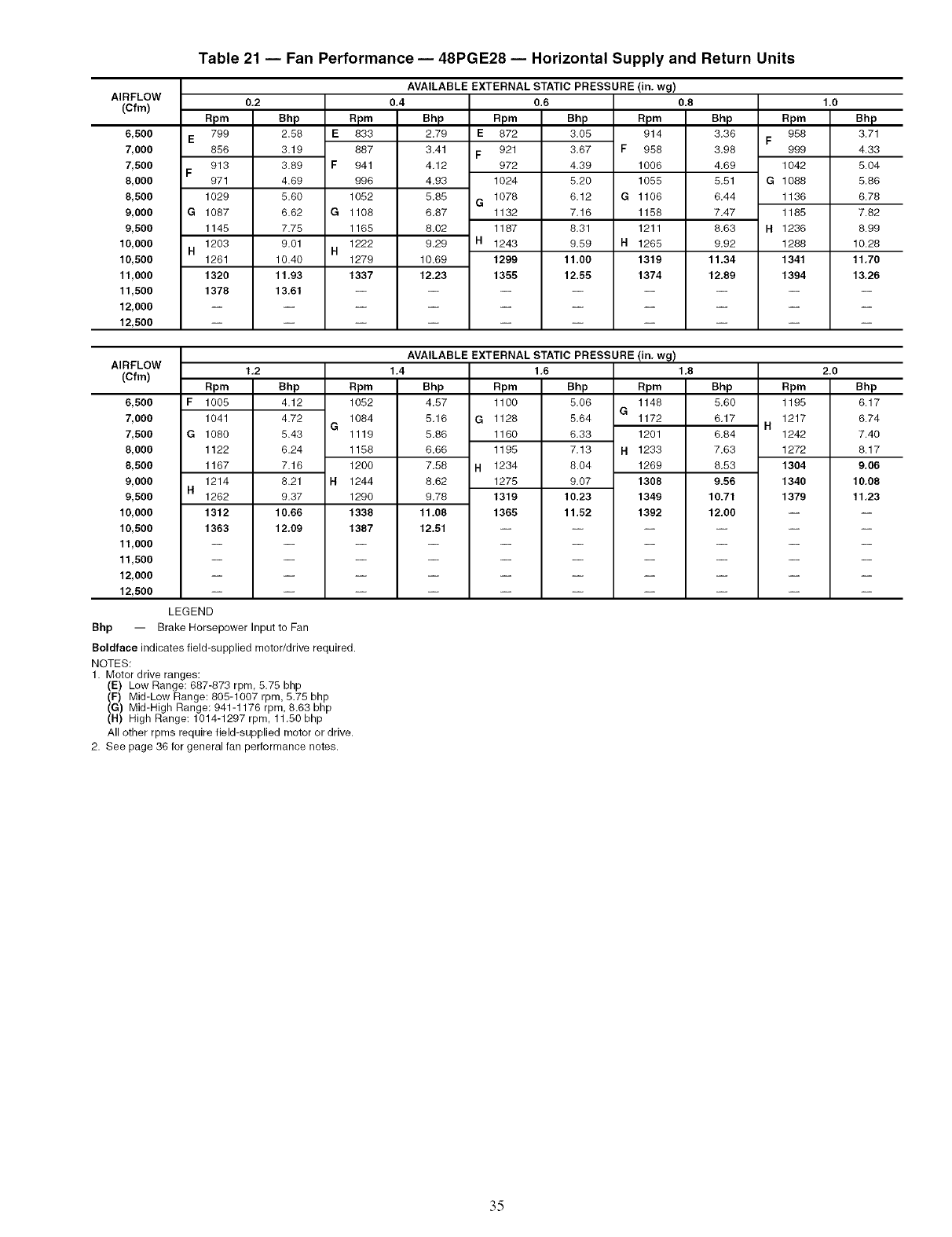
Table 21 -- Fan Performance -- 48PGE28 -- Horizontal Supply and Return Units
AVAILABLE EXTERNAL STATIC PRESSURE
AIRFLOW
(Cfm) 0,2
6,500
7,000
7,500
8,000
8,500
9,000
9,500
10,000
10,500
11,000
11,500
12,000
12,500
E
F
G
H
Rpm
799
856
913
971
1029
1087
1145
1203
1261
1320
1378
Bhp
2.58 E
3.19
3.89 F
4.69
5.60
6.62 G
7.75
9.01 H
10.40
11,93
13.61
apm
833
887
941
996
1052
1108
1165
1222
1279
1337
0,4
Bhp
2.79 E
3.41 F
4.12
4.93
5,85 G
6,87
8,02
9,29 H
10.69
12.23
0.6
Rpm Bhp
872 3.05
921 3.67 F
972 4.39
1024 5.20
1078 6.12 G
1132 7.16
1187 8.31
1243 9,59 H
1299 11.00
1355 12.55
(in. wg)
0.8
Rpm
914
958
1006
1055
1106
1158
1211
1265
1319
1374
Bhp
3,36
3.98
4,69
5,51
6.44
7.47
8,63
9,92
11.34
12.89
apm
958
F999
1042
G 1088
1136
1185
H1236
1288
1341
1394
1.0
Bhp
3.71
4.33
5.04
5.86
6.78
7.82
8.99
10.28
11,70
13,26
AIRFLOW 1,2
(Cfm)
6,500
7,000
7,500
8,000
8,500
9,000
9,500
10,000
10,500
11,000
11,500
12,000
12,500
F
G
Rpm
1005
1041
1080 5.43
1122 6.24
1167 7.16
1214 8.21 H
1262 9.37
1312 10,66
1363 12.09
Bhp Rpm
4.12 1052
4.72 1084
G
AVAILABLE EXTERNAL STATIC PRESSURE
1.4 1,6
Bhp Rpm Bhp
4.57 1100 5.06 G
5.16 G 1128 5.64
6,33
7.13
8.04
9,07
10.23
11.52
(in, wg)
1,8
Rpm
1148
1172
6.84
7.63
8.53
9.56
10.71
12.00
1119
1158
1200
1244
1290
1338
1387
5.86 1160
6.66 1195
7.58 H1234
8.62 1275
9.78 1319
11,08 1365
12,51
1201
H1233
1269
1308
1349
1392
Bhp Rpm
5.60 1195
6.17 1217
H1242
1272
1304
1340
1379
2.0
Bhp
6.17
6.74
7.40
8.17
9.06
10,08
11,23
LEGEND
Bhp -- Brake Horsepower Input to Fan
Boldface indicates field-supplied motor/drive required.
NOTES:
1. Motor drive ranges:
(E) Low Range: 687-873 rpm, 5.75 bhp
(F) Mid-Low Range: 805-1007 rpm, 5.75 bhp
(G) Mid-High Range: 941-1176 rpm, 8.63 bhp
(H) High Range: 1014-1297 rpm, 11.50 bhp
All other rpms require field-supplied motor or drive.
2. See page 36 for general fan performance notes.
35
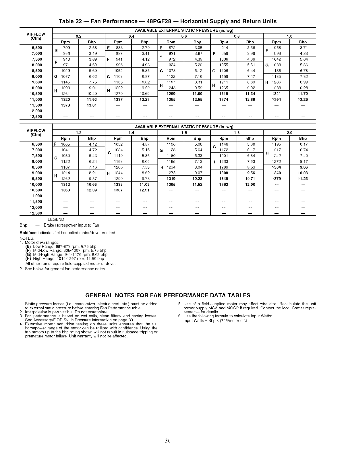
AIRFLOW
(Cfm)
6,500
7,000
7,500
8,000
8,500
9,000
9,500
10,000
10,500
11,600
11,500
12,000
12,500
E
F
G
H
Table 22 -- Fan Performance -- 48PGF28 -- Horizontal Supply and Return Units
AVAILABLE EXTERNAL STATIC PRESSURE (in. wg)
Rpm
799
856
913
971
1029
1087
1145
1203
1261
1320
1378
0,2
Bhp
2.58
3.19
3.89
4.69
5.60
6.62
7.75
9.01
10.40
11,93
13,61
E
F
G
H
Rpm
833
687
941
996
1052
1108
1165
1222
1279
1337
0.4
Bhp
2.79
3.41
4.12
4.93
5.85
6.87
8.02
9.29
10.69
12.23
Rpm
E 872
921
F972
1024
G 1076
1132
1187
H 1243
1299
1355
0.6
Bhp
3,05
3,67
4,39
5,20
6,12
7,16
8,31
9,59
11.00
12.55
Rpm
914
F 958
1006
1055
G 1106
1158
1211
H1265
1319
1374
0.8
Bhp
3.36
3.98
4.69
5.51
6.44
7.47
8.63
9.92
11.34
12.89
Rpm
958
F999
1042
G 1068
1136
1185
H 1236
1268
1341
1394
1.0
Bhp
3.71
4.33
5.04
5.86
6.78
7.82
8.99
10.28
11.70
13.26
AIRFLOW
(Cfm) 1.2 1.8 2.0
6,500
7,000
7,500
8,000
8,500
9,000
9,500
10,000
10,500
11,000
11,500
12,000
12,500
Bhp --
Rpm Bhp
1005 4.12
1041 4.72
Rpm
1052
1084
G
AVAILABLE EXTERNAL STATIC PRESSURE (in. wg)
1.4 1.6
Bhp Rpm Bhp Rpm
4.57 1100 5.06 1148
G
5.16 G 1128 5.64 1172
1160
1195
H 1234
1275
1319
1365
6.33 1201
7.13 H 1233
8.04 1269
9.07 1306
10.23 1349
11.52 1392
6.84
7.63
8.53
9,56
10.71
12.00
F
1080 5.43
G1122 6.24
1167 7.16
1214 8.21
H1262 9.37
1312 10.66
1363 12,09
LEGEND
B_ke HorsepowerlnputtoFan
1119
1156
1200
1244
1290
1338
1387
5.86
6.66
7.58
8.62
9.78
11.08
12.51
Bhp Rpm
5.80 1195
6.17 1217
H1242
1272
1304
1340
1379
Bhp
6.17
6.74
7.40
8.17
9.06
10.08
11.23
Boldface indicates field-supplied motor/drive required.
NOTES:
1. Motor drive ranges:
(E) Low Range: 687-873 rpm, 5.75 bhp
(F) Mid-Low Range: 605-1007 rpm, 5.75 bhp
(G) Mid-High Range: 941-1176 rpm, 8.63 bhp
(H) High Range: 1014-1297 rpm, 11.50 bhp
All other rpms require field-supplied motor or drive.
2. See below for general fan performance notes.
GENERAL NOTES FOR FAN PERFORMANCE DATA TABLES
1. Static pressure losses (i.e., economizer, electric heat, etc.) must be added
to external static pressure before entering Fan Performance table.
2. Interpolation is permissible. Do not extrapolate.
3. Fan performance is based on wet coils, clean filters, and casing losses.
See Accessory/FlOP Static Pressure information on page 39.
4. Extensive motor and drive testing on these units ensures that the full
horsepower range of the motor can be utilized with confidence. Using the
fan motors up to the bhp rating shown will not result in nuisance tripping or
premature motor failure. Unit warranty will not be affected.
5. Use of a field-supplied motor may affect wire size. Recalculate the unit
power supply MCA and MOCP if required. Contact the local Carrier repre-
sentative for details.
6. Use the following formula to calculate Input Watts:
Input Watts = Bhp x (746/motor effl)
36
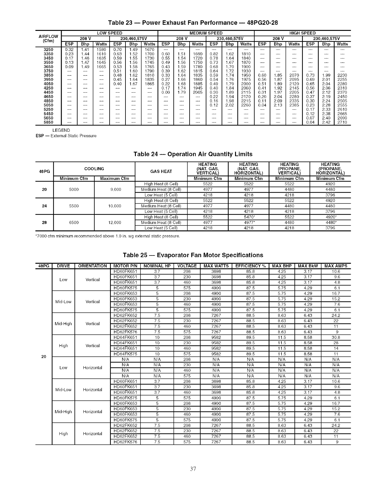
Table 23 -- Power Exhaust Fan Performance -- 48PG20-28
AIRFLOW
(Cfm)
3250
3350
3450
3550
3650
3750
3850
3950
4050
4250
4450
4650
4850 -- --
5050 -- --
5250 -- --
5450 -- --
5650 -- --
5850 -- --
LEGEND
ESP--External Static Pressure
LOW SPEED
208 V 230,460,575V
ESP Bhp Watts ESP Bhp Watts
0.32 1.41 1580 0.70 1.49 1670
0.23 1.44 1610 0.63 1.52 1700
0.17 1.46 1635 0.59 1.55 1730
0.13 1.47 1645 0.56 1.56 1745
0.09 1.49 1665 0.53 1.58 1765
MEDIUM SPEED
208 V 230,460,575V
ESP Bhp Watts ESP Bhp Watts
0.60 1.51 1690 0.82 1.62 1810
0.55 1.54 1720 0.78 1.64 1840
0.49 1.56 1750 0.73 1.67 1870
0.43 1.59 1780 0.68 1.70 1900
-- 0.51 1.60 1790
-- 0.48 1.62 1810
-- 0.45 1.64 1835
-- 0.40 1.67 1865
0.39 1.62 1815 0.64 1.72 1930
0.33 1.64 1835 0.59 1.74 1950
0.27 1.66 1860 0.54 1.76 1975
0.22 1.68 1885 0.49 1.79 2000
0.17 1.74 1945 0.40 1.84 2060
0.00 1.79 2005 0.30 1.89 2115
-- -- -- 0.22 1.94 2170
-- -- -- 0.16 1.98 2215
-- -- -- 0.12 2.02 2260
HIGH SPEED
208 V 230,460,575V
ESP Bhp Watts ESP Bhp Wa_s
0.60 1,85 2070 0.73 1.99 2230
0.56 1,87 2095 0.69 2.01 2255
0.51 1.89 2120 0.65 2.04 2280
0.41 1.92 2145 0.56 2.06 2310
0.31 1.97 2205 0.47 2.12 2370
0.20 2.04 2280 0.37 2.19 2450
0.11 2.09 2335 0.30 2.24 2505
0.04 2.13 2385 0.23 2.28 2555
-- -- -- 0.17 2.33 2610
-- -- -- 0.12 2.38 2665
-- -- -- 0.07 2.40 2690
-- -- -- 0.04 2.42 2710
48PG
20
24
28
Table 24 -- Operation Air Quantity Limits
COOLING
Maximum Cfm
9,000
10,000
12,000
GAS HEAT
Minimum Cfm
High Heat (8 Cell)
5000 Medium Heat (8 Cell)
Low Heat (5 Cell)
High Heat (8 Cell)
5500 Medium Heat (8 Cell)
Low Heat (5 Cell)
High Heat (8 Cell)
6500 Medium Heat (8 Cell)
Low Heat (5 Cell)
*7000 cfm minimum recommended above 1.0 in. wg external static pressure.
HEATING
(NAT. GAS,
VERTICAL)
Minimum Cfm
5522
4977
4218
5522
4977
4218
5522
4977
4218
HEATING
(NAT. GAS,
HORIZONTAL)
Minimum Cfm
5522
4977
4218
5522
4977
4218
5470*
4977*
4218
HEATING
(PROPANE,
VERTICAL)
Minimum Cfm
5522
4480
4218
5522
4480
4218
5522
4480
4218
HEATING
(PROPANE,
HORIZONTAL)
Minimum Cfm
4920
4480
3796
4920
4480
3796
4920*
4480*
3796
Table 25 -- Evaporator Fan Motor Specifications
48PG ORIENTATION MOTOR P/N NOMINAL HP VOLTAGE MAX WATTS EFFICIENCY %MAX BHP MAX BkW MAX AMPS
HD60FK651 3.7 208 3698 85.8 4.25 3.17 10.6
HD60 FK651 3.7 230 3698 85.8 4.25 3.17 9.6
Low Vertical HD60 FK651 3.7 460 3698 85.8 4.25 3.17 4.8
HD60FK575 5 575 4900 87.5 5.75 4.29 6.1
HD60FK653 5 208 4900 87.5 5.75 4.29 16.7
HD60FK653 5 230 4900 87.5 5.75 4.29 15.2
Mid-Low Vertical HD60FK653 5 460 4900 87.5 5.75 4.29 7.6
HD60FK575 5 575 4900 87.5 5.75 4.29 6.1
HD62FK652 7.5 208 7267 88.5 8.63 6.43 24.2
HD62FK652 7.5 230 7267 88.5 8.63 6.43 22
Mid-High Vertical HD62FK652 7.5 460 7267 88.5 8.63 6.43 11
HD62FK576 7.5 575 7267 88.5 8.63 6.43 9
HD64FK651 10 208 9582 89.5 11.5 8.58 30.8
HD64FK651 10 230 9582 89.5 11.5 8.58 28
High Vertical HD64 FK651 10 460 9582 89.5 11.5 8.58 14
HD64FK575 10 575 9582 89.5 11.5 8.58 11
20 N/A N/A 208 N/A N/A N/A N/A N/A
N/A N/A 230 N/A N/A N/A N/A N/A
Low Horizontal N/A N/A 460 N/A N/A N/A N/A N/A
N/A N/A 575 N/A N/A N/A N/A N/A
HD60FK651 3.7 208 3698 85.8 4.25 3.17 10.6
HD60FK651 3.7 230 3698 85.8 4.25 3.17 9.6
Mid-Low Horizontal HD60 FK651 3.7 460 3698 85.8 4.25 3.17 4.8
HD60FK575 5 575 4900 87.5 5.75 4.29 6.1
HD60FK653 5 208 4900 87.5 5.75 4.29 16.7
HD60FK653 5 230 4900 87.5 5.75 4.29 15.2
Mid-High Horizontal HD60FK653 5 460 4900 87.5 5.75 4.29 7.6
HD60FK575 5 575 4900 87.5 5.75 4.29 6.1
HD62FK652 7.5 208 7267 88.5 8.63 6.43 24.2
HD62FK652 7.5 230 7267 88.5 8.63 6.43 22
High Horizontal HD62FK652 7.5 460 7267 88.5 8.63 6.43 11
HD62FK576 7.5 575 7267 88.5 8.63 6.43 9
37
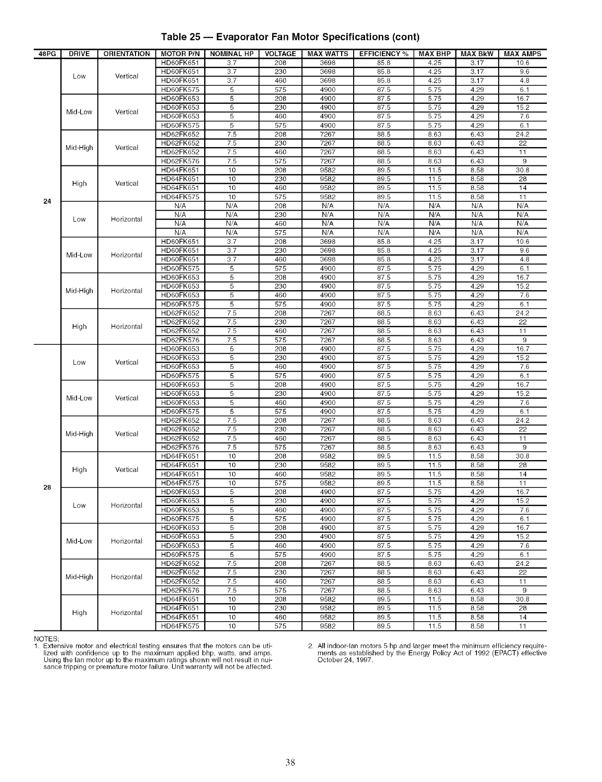
Table 25 -- Evaporator Fan Motor Specifications (cont)
48PG ORIENTATION MOTOR P/N NOMINAL HP VOLTAGE MAX WATTS EFFICIENCY %MAX BHP MAX BkW MAX AMPS
HD6OFK651 3.7 208 3698 85.8 4.25 3.17 10.6
HD60FK651 3.7 230 3698 85.8 4.28 3.17 9.6
Low Vertical HD60FK651 3.7 460 3698 85.8 4.28 3.17 4.8
HD60FK575 5 575 4900 87.5 5.75 4.29 6.1
HD60FK653 5 208 4900 87.8 5.75 4.29 16.7
HD60FK653 5 230 4900 87.5 5.75 4.29 15.2
Mid-Low Vertical HD60FK653 5 460 4900 87.5 5.75 4.29 7.6
HD60FK575 5 575 4900 87.5 5.75 4.29 6.1
HD62FK652 7.5 208 7267 88.5 8.63 6.43 24.2
HD62FK652 7.5 230 7267 88.8 8.63 6.43 22
Mid-High Vertical HD62FK652 7.5 460 7267 88.5 8.63 6.43 11
HD62FK576 7.5 575 7267 88.5 8.63 6.43 9
HD64FK651 10 208 9582 89.5 11.5 8.58 30.8
HD64FK651 10 230 9582 89.5 11.5 8.58 28
High Vertical HD64FK651 10 460 9582 89.8 11.5 8.58 14
HD64FK578 10 578 9582 89.8 11.5 8.58 11
24 N/A N/A 208 N/A N/A N/A N/A N/A
N/A N/A 230 N/A N/A N/A N/A N/A
Low Horizontal N/A N/A 460 N/A N/A N/A N/A N/A
N/A N/A 575 N/A N/A N/A N/A N/A
HD60FK651 3.7 208 3698 85.8 4.28 3.17 10.6
HD60FK651 3.7 230 3698 85.8 4.25 3.17 9.6
Mid-Low Horizontal HD60FK651 3.7 460 3698 85.8 4.28 3.17 4.8
HD60FK575 5 575 4900 87.5 5.75 4.29 6.1
HD60FK653 5 208 4900 87.5 5.75 4.29 16.7
HD60FK653 5 230 4900 87.8 5.75 4.29 15.2
Mid-High Horizontal HD60FK653 5 460 4900 87.5 5.75 4.29 7.6
HD60FK575 5 875 4900 87.5 5.75 4.29 6.1
HD62FK652 7.5 208 7267 88.5 8.63 6.43 24.2
HD62FK652 7.5 230 7267 88.5 8.63 6.43 22
High Horizontal HD62FK652 7.5 460 7267 88.8 8.63 6.43 11
HD62FK576 7.5 578 7267 88.8 8.63 6.43 9
HD60FK653 5 208 4900 87.5 5.75 4.29 16.7
HD60FK653 5 230 4900 87.5 5.75 4.29 15.2
Low Vertical HD60FK653 5 460 4900 87.5 5.75 4.29 7.6
HD60FK575 5 575 4900 87.5 5.75 4.29 6.1
HD60FK653 5 208 4900 87.8 5.75 4.29 16.7
HD60FK653 5 230 4900 87.8 5.75 4.29 15.2
Mid-Low Vertical HD60FK653 5 460 4900 87.8 5.75 4.29 7.6
HD60FK575 5 875 4900 87.5 5.75 4.29 6.1
HD62FK652 7.5 208 7267 88.5 8.63 6.43 24.2
HD62FK652 7.5 230 7267 88.5 8.63 6.43 22
Mid-High Vertical HD62FK652 7.5 460 7267 88.5 8.63 6.43 11
HD62FK576 7.5 578 7267 88.8 8.63 6.43 9
HD64FK651 10 208 9582 89.5 11.5 8.58 30.8
HD64FK651 10 230 9582 89.5 11.5 8.58 28
High Vertical HD64FK651 10 460 9582 89.5 11.5 8.58 14
HD64FK575 10 575 9582 89.5 11.5 8.58 11
28 HD60FK653 5 208 4900 87.8 5.75 4.29 16.7
HD60FK653 5 230 4900 87.5 5.75 4.29 15.2
Low Horizontal HD60FK653 5 460 4900 87.5 5.75 4.29 7.6
HD60FK575 5 575 4900 87.5 5.75 4.29 6.1
HD60FK653 5 208 4900 87.5 5.75 4.29 16.7
HD60FK653 5 230 4900 87.8 5.75 4.29 15.2
Mid-Low Horizontal HD60FK653 5 460 4900 87.8 5.75 4.29 7.6
HD60FK575 5 875 4900 87.5 5.75 4.29 6.1
HD62FK652 7.5 208 7267 88.5 8.63 6.43 24.2
HD62FK652 7.5 230 7267 88.5 8.63 6.43 22
Mid-High Horizontal HD62FK652 7.5 460 7267 88.5 8.63 6.43 11
HD62FK576 7.5 578 7267 88.8 8.63 6.43 9
HD64FK651 10 208 9582 89.5 11.5 8.58 30.8
HD64FK651 10 230 9582 89.5 11.5 8.58 28
High Horizontal HD64FK651 10 460 9582 89.5 11.5 8.58 14
HD64FK575 10 575 9582 89.5 11.5 8.58 11
NOTES:
1. Extensive motor and electrical testing ensures that the motors can be uti-
lized with confidence up to the maximum applied bhp, watts, and amps.
Using the fan motor up to the maximum ratings shown will not result in nui-
sance tripping or premature motor failure. Unit warranty will not be affected.
2. All indoor-fan motors 5 hp and larger meet the minimum efficiency require-
ments as established by the Energy Policy Act of 1992 (EPACT) effective
October 24, 1997.
38
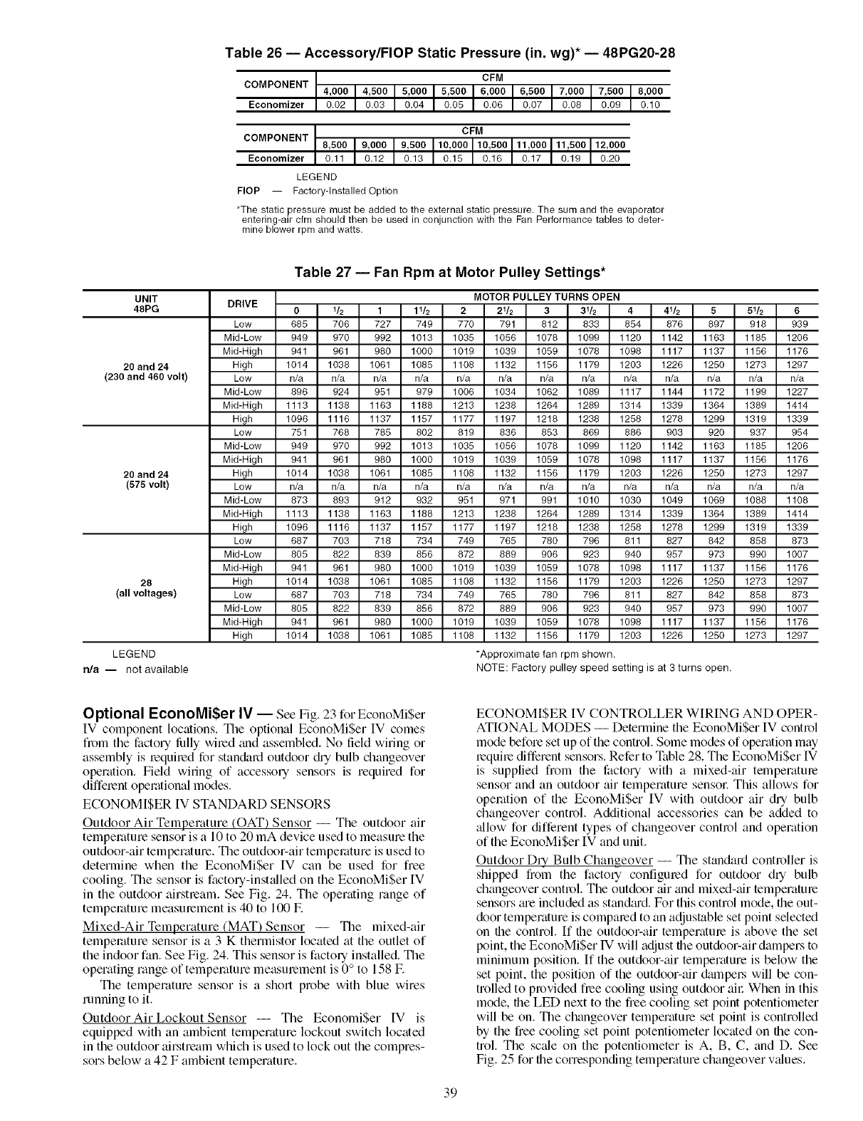
Table 26 -- Accessory/FlOP Static Pressure (in. wg)* -- 48PG20-28
CFM
COMPONENT 4,000 4,500 5,000 5,500 6,000 6,500 7,000 7,500 8,000
Economizer 0.02 0.03 0.04 0.05 0.06 0.07 0.08 0.09 0.10
CFM
COMPONENT 8,500 9,000 9,500 10,000 10,500 11,000 11,500 12,000
Economizer 0.11 0.12 0.13 0.15 0.16 0.17 0.19 0.20
LEGEND
FlOP -- Factory-Installed Option
*The static pressure must be added to the external static pressure. The sum and the evaporator
entering-air cfm should then be used in conjunction with the Fan Performance tables to deter-
mine blower rpm and watts.
UNIT
48PG
20 and 24
(230 and 460 volt)
20 and 24
(575 volt)
28
(all voltages)
LEGEND
rda -- not available
Table 27 Fan Rpm at Motor Pulley Settings*
DRIVE 01/2 1 11/2 221/2 3
Low 685 706 727 749 770 791 812
Mid-Low 949 970 992 1013 1035 1056 1078
Mid-High 941 961 980 1000 1019 1039 1059
High 1014 1038 1061 1085 1108 1132 1156
Low n/a n/a n/a n/a n/a n/a n/a
Mid-Low 896 924 951 979 1006 1034 1062
Mid-High 1113 1138 1163 1188 1213 1238 1264
High 1096 1116 1137 1157 1177 1197 1218
Low 751 768 785 802 819 836 853
Mid-Low 949 970 992 1013 1035 1056 1078
Mid-High 941 961 980 1000 1019 1039 1059
High 1014 1038 1061 1085 1108 1132 1156
Low n/a n/a n/a n/a n/a n/a n/a
Mid-Low 873 893 912 932 951 971 991
Mid-High 1113 1138 1163 1188 1213 1238 1264
High 1096 1116 1137 1157 1177 1197 1218
Low 687 703 718 734 749 765 780
Mid-Low 805 822 839 856 872 889 906
Mid-High 941 961 980 1000 1019 1039 1059
High 1014 1038 1061 1085 1108 1132 1156
Low 687 703 718 734 749 765 780
Mid-Low 805 822 839 856 872 889 906
Mid-High 941 961 980 1000 1019 1039 1059
High 1014 1038 1061 1085 1108 1132 1156
MOTOR PULLEY TURNS OPEN
31/2 4 41/2 5 51/2 6
833 854 876 897 918 939
1099 1120 1142 1163 1185 1206
1078 1098 1117 1137 1156 1176
1179 1203 1226 1250 1273 1297
n/a n/a n/a n/a n/a n/a
1089 1117 1144 1172 1199 1227
1289 1314 1339 1364 1389 1414
1238 1258 1278 1299 1319 1339
869 886 903 920 937 954
1099 1120 1142 1163 1185 1206
1078 1098 1117 1137 1156 1176
1179 1203 1226 1250 1273 1297
n/a n/a n/a n/a n/a n/a
1010 1030 1049 1069 1088 1108
1289 1314 1339 1364 1389 1414
1238 1258 1278 1299 1319 1339
796 811 827 842 858 873
923 940 957 973 990 1007
1078 1098 1117 1137 1156 1176
1179 1203 1226 1250 1273 1297
796 811 827 842 858 873
923 940 957 973 990 1007
1078 1098 1117 1137 1156 1176
1179 1203 1226 1250 1273 1297
*Approximate fan rpm shown.
NOTE: Factory pulley speed setting is at 3 turns open.
Optional EconoMiSer IV -- See Fig. 23 for EconoMi$er
IV component locations. The optional EconoMi$er IV comes
from the facto UfiJlly wiled and assembled. No field wiring or
assembly is required for standard outdoor c_h'ybulb changeover
operation. Field wiling of accessory sensors is required for
different operational modes.
ECONOMI$ER [V STANDARD SENSORS
Outdoor Air Temperature (OAT) Sensor -- The outdoor air
temperature sensor is a 10 to 20 mA device used to measure the
outdoor-air temperature. The outdoor-air temperature is used to
determine when the EconoMi$er IV can be used for free
cooling. The sensor is factory-inst_flled on the EconoMiSer [V
in the outdoor airstream. See Fig. 24. The operating range of
temperature measurement is 40 to 100 E
Mixed-Air Temperature (MAT) Sensor -- The mixed-air
temperature sensor is a 3 K thermistor located at the outlet of
the indoor fan. See Fig. 24. This sensor is facto Uinstalled. The
operating range of temperature measurement is 0 ° to 158 E
The temperature sensor is a short probe with blue wires
running to it.
Outdoor Air Lockout Sensor -- The Economi$er IV is
equipped with an ambient temperature lockout switch located
in the outdoor airstream which is used to lock out the compres-
sors below a 42 F ambient temperature.
ECONOMISER IV CONTROLLER WIRING AND OPER-
ATIONAL MODES -- Determine the EconoMiSer IV control
mode before set up of the control. Some modes of operation may
lequile different sensors. Refer to N_ble 28. The EconoMi$er IV
is supplied from the factory with a mixed-air temperatme
sensor and an outdoor air temperature sensol: This allows for
operation of the EconoMiSer IV with outdoor air dry bulb
changeover control. Additional accessories can be added to
_fllow for different types of changeover control and operation
of the EconoMiSer IV and unit.
Outdoor D UBulb Changeover -- The standard controller is
shipped from the facto qconfigured for outdoor dry bulb
changeover control. The outdoor _firand mixed-tfir temperature
sensors tue included as stand_u'd. For this control mode, the out-
door temperature is compared to an adjustable set point selected
on the control. If the outdoor-air temperature is above the set
point, the EconoMi$er IV will adjust the outdoor-air dampers to
minimum position. If the outdoor-air temperature is below the
set point, the position of the outdoor-air &unpeLs will be con-
trolled to provided free cooling using outdoor all: When in this
mode, the LED next to the free cooling set point potenfiometer
will be on. The changeover temperature set point is controlled
by the free cooling set point potentiometer located on the con-
trol. The sc_fle on the potentiometer is A, B, C, and D. See
Fig. 25 for the corresponding temperature changeover values.
39
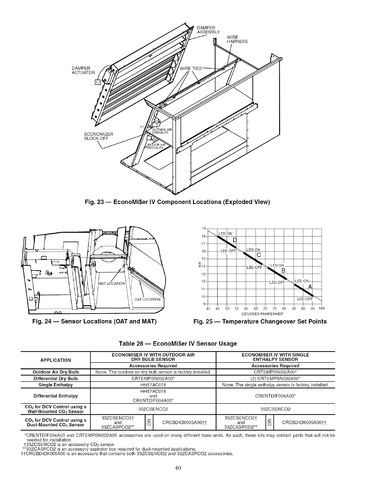
DAMPER
ASSEMBLY
WIRE
HARNESS
DAMPER
ACTUATOR
ECONOMIZER
BLOCK OFF
Fig. 23 -- EconoMiSer IV Component Locations (Exploded View)
Fig. 24 -- Sensor Locations (OAT and MAT)
19.
18- '''% LEDON
17-
16- -- - LED O FF
15-
<
E14-
13-
12-
11-
10-
LED ON
LED OFF -
40 45 50 55 60 65 70 75 80
DEGREES FAHRENHEIT
Fig. 25 -- Temperature Changeover Set Points
Table 28 -- EconoMi$er IV Sensor Usage
ECONOMI$ER IV WITH SINGLE
APPLICATION ENTHALPY SENSOR
Accessories Required
Outdoor Air Dry Bulb CRTEMPSN002A00 _
Differential Dry Bulb (2) CRTEMPSN002A00 _
Single Enthalpy None. The single enthalpy sensor is factory installed.
CRENTDIF004A00 _
Differential Enthalpy
CO2 for DCV Control using a
Wall-Mounted CO2 Sensor
CO2 for DCV Control using a
Duct-Mounted 002 Sensor
ECONOMI$ER IV WITH OUTDOOR AIR
DRY BULB SENSOR
Accessories Required
None. The outdoor air dry bulb sensor is factory installed.
CRTEMPSN002A00 _
HH57AC078
HH57AC078
and
CRENTDIF004A00 _
33ZCSENCO2
33ZCSENCO2t
and CRCBDIOX005A00tt
33ZCASPCO2**
33ZCSENCO2
33ZCSENCO2t
and CRCBDIOX005A00tt
33ZCASPCO2**
-CRENTDIF004A00 and CRTEMPSN002A00 accessories are used on many different base units. As such, these kits may contain parts that will not be
needed for installation.
t33ZCSENCO2 is an accessory CO2 sensor.
-'33ZCASPCO2 is an accessory aspirator box required for duct-mounted applications.
ttCRCBDiOX005A00 is an accessory that contains both 33ZCSENCO2 and 33ZCASPCO2 accessories.
40
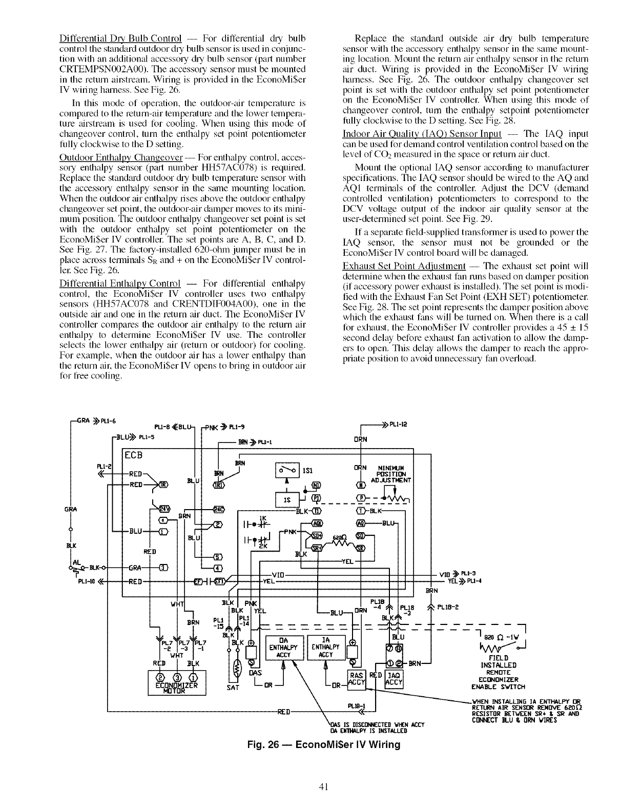
Differential Dry Bulb Control -- For differentM c_h-ybulb
control tile stan_u_d outdoor dry bulb sensor is used in conjunc-
tion with an addition',fi accesso U&-y bulb sensor (part number
CRTEMPSN002A00). Tile accesso Usensor must be mounted
in the return ail_tream. Wiring is provided in the EconoMiSer
IV wiling htuness. See Fig. 26.
In this mode of operation, the outdoor-air temperature is
compared to the leturn-air temperature and the lower tempera-
ture airstream is used for cooling. When using this mode of
changeover control, turn the enthalpy set point potentiometer
fully clockwise to the D setting.
Outdoor Enthalpy Changeover -- For enth_dpy contl_)l, acces-
sory enthalpy sensor (pa-t number HH57AC078) is required.
Replace the standm_d outdoor c_h-ybulb temperatule sensor with
the accesso Uenthalpy sensor in the same mounting location.
When the outdoor air enthalpy rises above the outdoor enthalpy
changeover set point, the outdoor-air &tmper moves to its mini-
mum position. The outdoor enthalpy changeover set point is set
with the outdoor enthalpy set point potentiometer on the
EconoMiSer IV controllel: The set points tu_eA, B, C, and D.
See Fig. 27. The factory-installed 620-ohm jumper must be in
place across termin_ds SR and + on the EconoMiSer IV control-
lel: See Fig. 26.
Differential Enthalpy Control -- For differentM enthalpy
control, the EconoMiSer IV controller uses two enthalpy
sensors (HH57AC078 and CRENTDIF004A00), one in the
outside air and one in the return air duct. The EconoMiSer IV
controller compares the outdoor air enthalpy to the return air
enthalpy to determine EconoMiSer IV use. The controller
selects the lower enthalpy air (return or outdoor) for cooling.
For example, when the outdoor air has a lower enthalpy than
the return ail: the EconoMiSer IV opens to bring in outdoor air
for free cooling.
Replace the standard outside air dry bulb temperature
sensor with the accesso Uenthalpy sensor in the same mount-
ing location. Mount the return air enthalpy sensor in the return
air duct. Wiring is provided in the EconoMiSer IV wiring
harness. See Fig. 26. The outdoor enth_dpy changeover set
point is set with the outdoor enthalpy set point potentiometer
on the EconoMi$er IV controllel: When using this mode of
changeover control, turn the enthalpy setpoint potentiometer
fully clockwise to the D setting. See Fig. 28.
Indoor Air Quality (IAQ) Sensor Input -- Tile IAQ input
can be used for demand control ventilation control based on the
level of CO2 measured in the space or return air duct.
Mount the optional IAQ sensor according to manufacturer
specifications. The IAQ sensor should be wired to the AQ and
AQI terminals of the controllel: Adjust the DCV (demand
controlled ventilation) potentiometel_ to correspond to the
DCV voltage output of the indoor air quality sensor at the
user-determined set point. See Fig. 29.
If a separate field-supplied transformer is used to power the
IAQ sensor, the sensor must not be grounded or the
EconoMiSer IV control board will be dmnaged.
Exhaust Set Point Adjustment -- The exhaust set point will
determine when the exhaust fan runs based on dmnper position
(if accessory power exhaust is insLdled). The set point is modi-
fied with the Exhaust Fan Set Point (EXH SET) potentiometel:
See Fig. 28. The set point represents the damper position above
which the exhaust fans will be turned on. When there is a c_dl
for exhaust, the EconoMiSer IV controller provides a 45 _+15
second delay before exhaust fan activation to allow the damp-
ers to open. This delay allows the damper to leach the appro-
priate position to avoid unnecessa-y fan overload.
Fig. 26 -- EconoMiSer IV Wiring
41
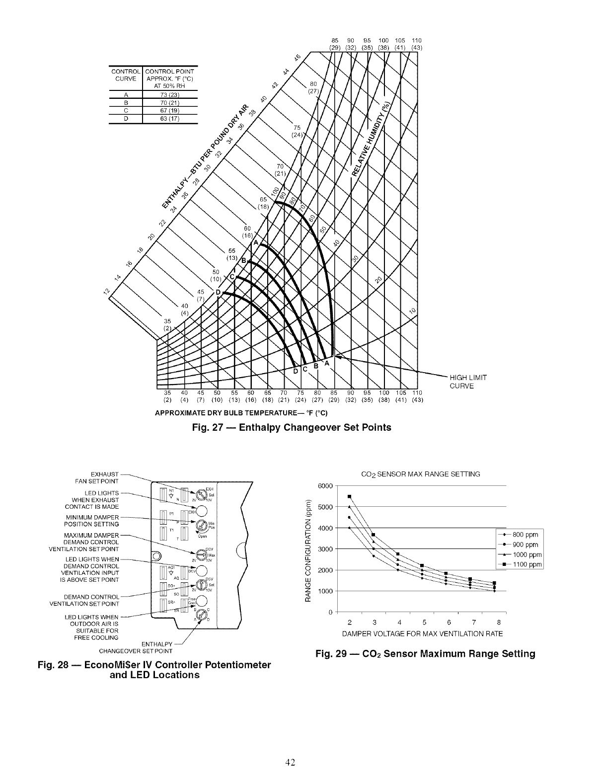
CONTROL CONTROL POINT
CURVE APPROX. °F (°C)
AT 50% RH
A 73 (23)
B 70 (21)
C 67(19)
D 63(17)
85 90 95 100 105 110
(29) (32) (35) (38) (41) (43)
-\
7-.
\\
7z
/
\
_4
\
\
X
-\
HIGH LIMIT
\ CURVE
35 40 45 50 55 60 65 70 75 80 85 90 95 100 105 110
(2) (4) (7) (10) (13) (16) (18) (21) (24) (27) (29) (32) (35) (38) (41) (43)
oo
APPROXIMATE DRY BULB TEMPERATURE i F (C)
Fig. 27 -- Enthalpy Changeover Set Points
EXHAUST
FAN SET POINT
LED LIGHTS
WHEN EXHAUST
CONTACT IS MADE
MINIMUM DAMPER
POSITION SETTING
MAXIMUM DAMPER
DEMAND CONTROL
VENTILATION SET POINT
LED LIGHTS WHEN
DEMAND CONTROL
VENTILATION INPUT
IS ABOVE SET POINT
DEMAND CONTROL
VENTILATION SET POINT
LED LIGHTS WHEN
OUTDOOR AIR IS
SUITABLE FOR
FREE COOLING ENTHALPY
CHANGEOVER SET POINT
Fig. 28 -- EconoMi$er IV Controller Potentiometer
and LED Locations
6000
5000
z4000
3000
E
Z
2000
w
Z 1000
<
0
CO2 SENSOR MAX RANGE SEqq-ING
_ +6oopp_I
I
_1000 ppm
_1100 ppm
23 45678
DAMPER VOLTAGE FOR MAX VENTILATION RATE
Fig. 29 -- CO2 Sensor Maximum Range Setting
42
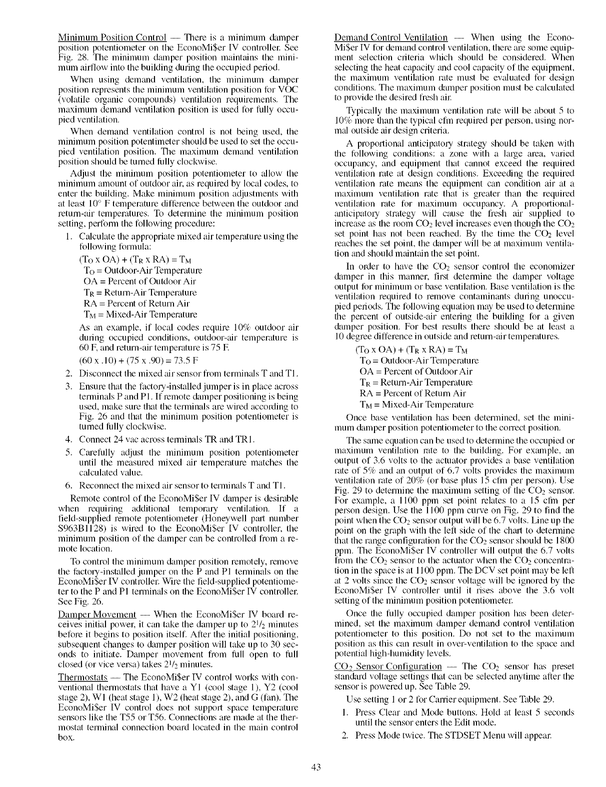
Minimum Position Control -- There is a minimum &tmper
position potentiometer on the EconoMiSer IV controllel: See
Fig. 28. The minimum dmnper position maintains the mini-
mum airflow into the building during the occupied period.
When using demand ventilation, the minimum damper
position represents the minimum ventilation position for VOC
(volatile organic compounds) ventilation requirements. The
maximum demand ventilation position is used for fully occu-
pied ventilation.
When demand ventilation control is not being used, the
minimum position potentimeter should be used to set the occu-
pied ventilation position. Tile maximum demand ventilation
position should be turned liflly clockwise.
Adjust the minimum position potentiometer to _dlow the
minimum amount of outdoor air. as required by local codes, to
enter the building. Make minimum position adjustments with
at least 10° F temperature difference between the outdoor and
return-air temperatures. To determine the minimum position
setting, perfoml the following procedure:
1. Calculate the appropriate mixed air temperature using the
following formula:
(To x OA) + (TR x RA) = TM
To = Outdoor-Air Temperature
OA = Percent of Outdoor Air
TR = Return-Air Temperature
RA = Percent of Return Air
TM = Mixed-Air Temperature
As an example, if local codes require 10% outdoor air
during occupied conditions, outdoor-air temperature is
60 IF.and return-air temperature is 75 IF.
(60 x. 10) + (75 x .90) = 73.5 F
2. Disconnect the mixed air sensor from termimfls T and TI.
3. Ensure that the factory-installed jumper is in place across
terminals P and PI. If remote &tmper positioning is being
used, make sure that the terminals are wired according to
Fig. 26 and that file minimum position potentiometer is
turned liflly clockwise.
4. Connect 24 vac across terminals TR and TRI.
5. Cmefully adjust the minimum position potentiometer
until the measured mixed air temperature matches the
c_dculated v_due.
6. Reconnect the mixed air sensor to terminals T and TI.
Remote control of the EconoMiSer IV dmnper is desirable
when requiring additional temporary ventilation. If a
field-supplied remote potentiometer (Honeywell p_ut number
$963B1128) is wired to the EconoMiSer IV controller, the
minimum position of the damper can be controlled from a re-
mote location.
To control the minimum &tmper position remotely, remove
the factory-installed jumper on the P and PI temlinals on the
EconoMiSer IV controllel: Wire the field-supplied potentiome-
ter to the P and PI termimds on file EconoMiSer IV controllel:
See Fig. 26.
Damper Movement -- When the EconoMiSer 1V board re-
ceives initial powel: it can take the damper up to 21/2 minutes
before it begins to position itself. After the initial positioning,
subsequent changes to &tmper position will take up to 30 sec-
onds to initiate. Damper movement from full open to full
closed (or vice velsa) takes 21/2 minutes.
Thermostats -- The EconoMiSer IV control works with con-
ventional thermostats that have a YI (cool stage 1), Y2 (cool
stage 2), WI (heat stage 1), W2 (heat stage 2), and G (fan). The
EconoMiSer IV control does not support space temperature
sensors like the T55 or T56. Connections are made at the tiler-
mostat terminal connection board located in the main control
box.
Demand Control Ventilation -- When using the Econo-
MiSer IV for demand control ventilation, there are some equip-
ment selection criteria which should be considered. When
selecting the heat capacity and cool capacity of the equipment,
the maximum ventilation rate must be ev_duated for design
conditions. The maximum &tmper position must be calculated
to provide the desired fresh all:
Typically the maximum ventilation rate will be about 5 to
10% more than the typical cfm required per pelion, using nor-
mid outside air design criteria.
A proportional anticipatory strategy should be taken with
the following conditions: a zone with a large area, varied
occupancy, and equipment that cannot exceed the required
ventilation rate at design conditions. Exceeding file required
ventihttion rate means the equipment can condition air at a
maximum ventilation rate that is greater than file required
ventilation rate for maximum occupancy. A proportional-
anticipatory strategy will cause tile fresh air supplied to
increase as file room CO2 level increases even though the CO2
set point has not been reached. By the time the CO2 level
reaches the set point, the &tmper will be at maximum ventila-
tion and should mainttfin the set point.
In order to have the CO2 sensor control tile economizer
&tmper in this manner, first determine the damper voltage
output for minimum or base ventilation. Base ventilation is the
ventilation required to remove contaminants during unoccu-
pied periods. The following equation may be used to determine
tile percent of outside-air entering the building for a given
&tmper position. For best results there should be at least a
10 degree difference in outside and return-air temperatures.
(To x OA) + (TR x RA) = TM
To = Outdoor-Air Temperature
OA = Percent of Outdoor Air
TR = Return-Air Temperature
RA = Percent of Return Air
TM = Mixed-Air Temperature
Once base ventilation has been determined, set the mini-
mum &tmper position potentiometer to the correct position.
The same equation can be used to determine the occupied or
maximum ventihttion rote to the building. For exmnple, an
output of 3.6 volts to the actuator provides a base ventilation
rate of 5% and an output of 6.7 volts provides tile maximum
ventihttion rate of 20% (or base plus 15 cfm per person). Use
Fig. 29 to determine the maximum setting of the CO2 sensor.
For example, a 1100 ppm set point relates to a 15 cfin per
person design. Use the 1100 ppm curve on Fig. 29 to find the
point when the CO2 sensor output will be 6.7 volts. Line up the
point on the graph with the left side of the chm't to determine
timt the range configuration for the CO2 sensor should be 1800
ppm. The EconoMiSer IV controller will output tile 6.7 volts
from the CO2 sensor to the actuator when the CO2 concentra-
tion in the space is at 1100 ppm. The DCV set point may be left
at 2 volts since the CO2 sensor voltage will be ignored by the
EconoMiSer IV controller until it rises above the 3.6 volt
setting of the minimum position potentiometer
Once tile fully occupied damper position has been deter-
mined, set the maximum damper demand control ventilation
potentiometer to this position. Do not set to the maximum
position as this can result in over-ventilation to the space and
potential high-humidity levels.
CO.2 Sensor Configuration -- The CO2 sensor has preset
stan&trd voltage settings that can be selected anytime after the
sensor is powered up. See Table 29.
Use setting 1 or 2 for Carrier equipment. See Table 29.
1. Press Clear and Mode buttons. Hold at least 5 seconds
until the sensor enters the Edit mode.
2. Press Mode twice. The STDSET Menu will appem:
43
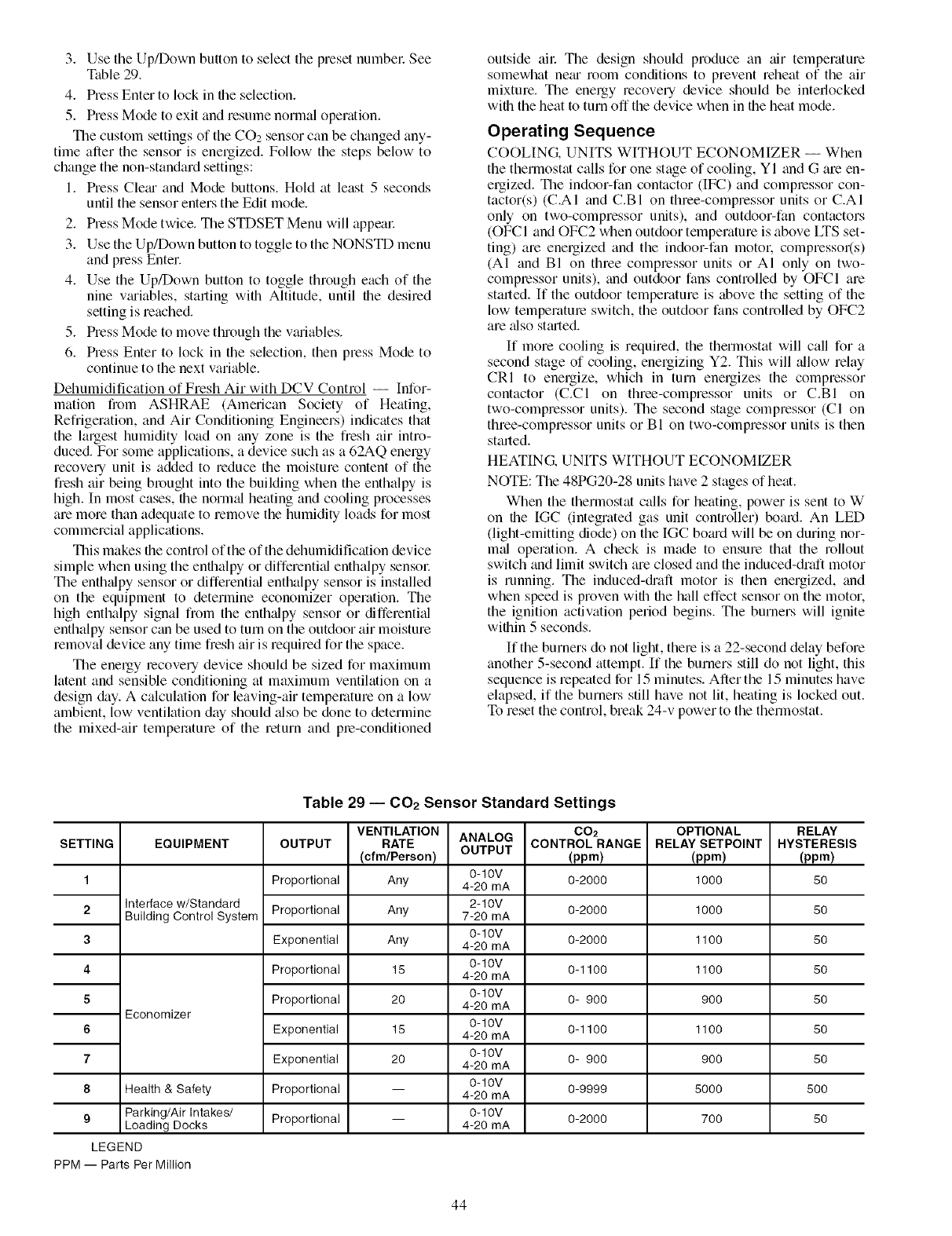
3. UsetheUp/Downbuttontoselectthepresetnumbel:See
Table29.
4. PressEntertolockinfileselection.
5. PressModetoexitandresumenormaloperation.
ThecustomsettingsoftheCO2sensorcanbechangedany-
timeafterthesensorisenergized.Followthestepsbelowto
changethenon-standardsettings:
1. PressCletuandModebuttons.Holdatleast5 seconds
untilthesensorenterstheEditmode.
2. PressModetwice.TheSTDSETMenuwillappeal:
3. UsetheUp/DownbuttontotoggletotheNONSTDmenu
andpressEnter.
4. UsetheUp/Downbuttontotogglethrougheachofthe
ninevmiables,startingwithAltitude,untilfiledesired
settingisreached.
5. PressModetomovethroughthevmiables.
6. PressEntertolockin theselection,thenpressModeto
continuetothenextvariable.
Dehumidification of Fresh Air with DCV Control -- Infor-
mation from ASHRAE (American Society of Heating,
Refrigeration, and Air Conditioning Engineers) indicates that
the largest humidity load on tiny zone is the fresh air intro-
duced. For some applications, a device such as a 62AQ energy
recovery unit is added to reduce the moisture content of the
fiesh air being brought into the building when the enthalpy is
high. In most cases, file norm_d heating and cooling processes
are more than adequate to remove the humidity loads for most
commercial applications.
This makes file control of the of the dehumidification device
simple when using the enthalpy or differenti_d enthalpy sensol:
The enth_dpy sensor or differenti_d enthalpy sensor is installed
on the equipment to determine economizer operation. The
high enthalpy signal from the enth_dpy sensor or differenti_d
enthalpy sensor can be used to turn on the outdoor air moisture
removal device any time fresh air is required for the space.
The energy recovery device should be sized for maximum
latent and sensible conditioning at maximum ventilation on a
design &ly. A calculation for leaving-air temperature on a low
ambient, low ventilation day should _flsobe done to determine
the mixed-air temperature of the return and pre-conditioned
outside ail: The design should produce an air temperature
somewhat netu room conditions to prevent reheat of the air
mixture. The energy recovery device should be interlocked
with the heat to turn off the device when in the heat mode.
Operating Sequence
COOLING. UNITS WITHOUT ECONOMIZER -- When
the thermostat calls for one stage of cooling, YI and G are en-
ergized. The indoor-fan contactor (IF(;_) and compressor con-
tactor(s) (C.AI and C.BI on three-compressor units or C.AI
only on two-compressor units), and outdoor-fan contactors
(OFCI and OFC2 when outdoor temperature is above LTS set-
ting) are energized and the indoor-fan motor, compressor(s)
(AI and BI on three compressor units or AI only on two-
compressor units), and outdoor fans controlled by OFCI are
stinted. If the outdoor temperature is above the setting of the
low temperature switch, the outdoor fans controlled by OFC2
are _dso stmted.
If more cooling is required, the therlnostat will cMl for a
second stage of cooling, energizing Y2. This will _fllow relay
CRI to energize, which in turn energizes the compressor
contactor (C.CI on three-compressor units or C.BI on
two-compressor units). The second stage compressor (CI on
three-compressor units or B I on two-compressor units is then
stmtedi
HEATING. UNITS WITHOUT ECONOMIZER
NOTE: The 48PG20-28 units have 2 stages of heat.
When the thermostat calls for heating, power is sent to W
on file [GC (integrated gas unit controller) board. An LED
(light-emitting diode) on the IGC bomd will be on during nor-
mifl operation. A check is made to ensure that the rollout
switch and limit switch are closed and the induced-draft motor
is running. The induced-di'aft motor is then energized, and
when speed is proven with the hall effect sensor on the motor.
the ignition activation period begins. The burners will ignite
within 5 seconds.
If the burners do not light, there is a 22-second delay before
another 5-second attempt. If the burners still do not light, this
sequence is repeated for 15 minutes. After the 15 minutes have
elapsed, if the burners still have not lit, heating is locked out.
To reset the control, break 24-v power to the thermostat.
Table 29 -- 002 Sensor Standard Settings
ANALOG
OUTPUT
SETTING
1
2
3
4
5
6
7
8
EQUIPMENT
Interface w/Standard
Building Control System
Economizer
Health & Safety
9 Parking/Air Intakes/
Loading Docks
LEGEND
PPM -- Parts Per Million
OUTPUT
Proportional
Proportional
Exponential
Proportional
Proportional
Exponential
Exponential
Proportional
Proportional
VENTILATION
RATE
(cfm/Pereon)
Any
Any
Any
15
20
15
20
0-10V
4-20 mA
2-10V
7-20 mA
0-10V
4-20 mA
0-10V
4-20 mA
0-10V
4-20 mA
0-10V
4-20 mA
0-10V
4-20 mA
0-10V
4-20 mA
0-10V
4-20 mA
CO2
CONTROLRANGE
(ppm)
0-2000
0-2000
0-2000
0-1100
0- 900
0-1100
0- 900
0-9999
0-2000
OPTIONAL
RELAY SETPOINT
(ppm)
1000
1000
1100
1100
900
1100
900
5000
700
RELAY
HYSTERESIS
(ppm)
5O
5O
5O
5O
5O
5O
5O
5O0
5O
44
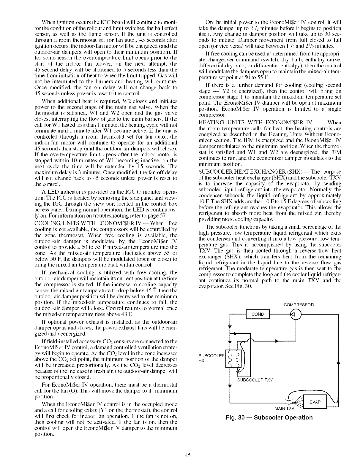
When ignition occurs the IGC board will continue to moni-
tor the condition of the rollout and limit switches, the hall effect
sensol: as well as the flame sensor. If the unit is controlled
through a morn thermostat set for fan auto., 45 seconds after
ignition occurs, the indoor-fan motor will be energized (and the
outdoor-tdr dampers will open to their minimum position). If
for some leason the overtemperature limit opens prior to the
start of the indoor fan blower, on the next attempt, the
45-second delay will be shortened to 5 seconds less than the
time fi_m initiation of heat to when the limit tripped. Gas will
not be interrupted to the burners and heating will continue.
Once modified, the fan on delay will not change back to
45 seconds unless power is reset to the control.
When additional heat is required, W2 closes and initiates
power to the second stage of the main gas valve. When the
thermostat is satisfied, WI and W2 open and the gas valve
closes, interrupting the flow of gas to the main burners. If the
call forWl lasted less than 1 minute, the heating cycle will not
terminate until 1 minute after WI became active. If the unit is
controlled through a room thermostat set for fan auto., the
indoor-fan motor will continue to operate for an additional
45 seconds then stop (and the outdoor-air dmnpers will close).
If the overtemperature limit opens after the indoor motor is
stopped within 10 minutes of WI becoming inactive, on the
next cycle the time will be extended by 15 seconds. The
maximum delay is 3 minutes. Once modified, the fan off delay
will not change back to 45 seconds unless power is reset to
the control.
A LED indicator is provided on the IGC to monitor opera-
tion. The IGC is located by removing the side panel and view-
ing the IGC through the view port located in the control box
access panel. During normal operation, the LED is continuous-
ly on. For information on tmubleshoofing refer to page 57.
COOLING. UNITS WITH ECONOMI$ER IV -- When free
cooling is not available, the compressol_ will be controlled by
the zone thermostat. When fiee cooling is available, the
outdoor-air damper is modulated by the EconoMiSer IV
control to provide a 50 to 55 F mixed-air temperature into the
zone. As the mixed-tdr temperature fluctuates above 55 or
below 50 E the dampers will be modulated (open or close) to
bring the mixed air temperature back within control.
If mechanical cooling is utilized with free cooling, the
outdoor-air damper will maintain its current position at the time
the compressor is started. If the increase in cooling capacity
causes the mixed-tdr temperature to di'op below 45 E then the
outdoor-tdr dmnper position will be decreased to the minimum
position. If the mixed-air temperature continues to fall, the
outdoor-air damper will close. Control returns to normal once
the mixed-air temperature rises above 48 E
If optional power exhaust is installed, as the outdoor-air
damper opens and closes, the power exhaust fans will be ener-
gized and deenergized.
If field-installed accesso UCO2 sensors are connected to the
EconoMiSer IV control, a demand controlled ventilation strate-
gy will begin to operate. As the CO*_level in the zone increases
above the CO2 set point, the minimum position of the damper
will be increased proportionally. As the CO2 level decreases
because of the increase in fresh all: the outdoor-air damper will
be proportionally closed.
For EconoMiSer IV operation, them must be a thermostat
call for the fan (G). This will move the damper to its minimum
position.
When the EconoMiSer IV control is in the occupied mode
and a call for cooling exists (YI on the thermostat), the control
will first check for indoor fan operation. If the fan is not on,
then cooling will not be activated. If the fan is on, then the
control will open the EconoMiSer IV dmnper to the minimum
position.
On the initkd power to the EconoMiSer [V control, it will
take the dmnper up to 21/2 minutes before it begins to position
itself. Any change in damper position will take up to 30 sec-
onds to initiate. Damper movement from full closed to full
open (or vice versa) will take between 11/2and 21/2 minutes.
If free cooling can be used as determined fi_m the appropri-
ate changeover command (switch, dry bulb, enthalpy curve,
differential dry bulb, or differential enthalpy), then the control
will modulate the dampers open to maintain the mixed-air tem-
perature set point at 50 to 55 E
If there is a further demand for cooling (cooling second
stage -- Y2 is energized), then the control will bring on
compressor stage 1 to maintain the mixed-air temperature set
point. The EconoMiSer IV damper will be open at maximum
position. EconoMiSer IV operation is limited to a single
compressor
HEATING UNITS WITH ECONOMI$ER IV -- When
the room temperature calls for heat, the heating controls am
energized as described in the Heating, Units Without Econo-
mizer section. The IFM is energized and the EconoMi$er IV
damper modulates to the minimum position. When the thermo-
stat is satisfied and Wl and W2 are deenergized, the IFM
continues to ran, and the economizer damper modulates to the
minimum position.
SUBCOOLER HEAT EXCHANGER (SHX) -- The purpose
of the subcooler heat exchanger (SHX) and the subcooler TXV
is to increase the capacity of the evaporator by sending
subcooled liquid refrigerant into the evaporatol: Normally, the
condenser subcools the liquid refrigerant by approximately
10 F. The SHX adds another 10 F to 15 F degrees of subcooling
before the refrigerant reaches the evaporator This allows the
refrigerant to absorb more heat from the mixed ail. thereby
providing more cooling capacity.
The subcooler fimctions by taking a small percentage of the
high pressure, low temperature liquid refrigerant which exits
the condenser and converting it into a low pressure, low tem-
perature gas. This is accomplished by using the subcooler
TXV. The gas is then routed through a reverse-flow heat
exchanger (SHX), which transfers heat from the remaining
liquid refrigerant in the liquid line to the reverse flow gas
refrigerant. The moderate temperature gas is then sent to the
compressor to complete the loop and the cooler liquid refriger-
ant continues its normal path to the main TXV and the
evaporator See Fig. 30.
SUBCOOLER
HX
COMPRESSOR
y
SUBCOOLERTXV
MAIN_
Fig. 30 -- Subcooler Operation
45
SERVICE
Before performing service or maintenance operations on
unit, turn off main power switch to unit. Electrical shock
could cause personal injury.
Puron® (R-410A) refiiger_mt systems operate at higher
pressures than standard R-22 systems. Do not use R-22
service equipment or components on Puron refrigerant
equipment. If service equipment is not rated for Puron
refrigerant, equipment &image or personal injury may
result.
I. Improper inst_fllation, adjustment, _flteration, service,
or maintenance ctm cause property dmnage, peLsonal
injury, or loss of life. Refer to the User's Information
Manual provided with this unit for more details.
2. Do not store or use gasoline or other flmnmable
vapors and liquids in the vicinity of this or any other
appliance.
What to do if you smell gas:
1. DO NOT try to light any appliance.
2. DO NOT touch any electrical switch, or use any
phone in your building.
3. IMMEDIATELY call your gas supplier from a neigh-
bor's phone. Follow the gas supplier's instructions.
4. If you cannot reach your gas supplier, call the fire
department.
This will make cleaning efforts morn difficult. Surface loaded
fibeL's must be completely removed prior to using low velocity
clean water rinse.
Periodic Clean W_ter Rinse --A periodic clean water rinse is
very beneficial for coils that are applied in coastal or industri_fl
environments. However. it is very important that the water
rinse is made with very low velocity water stream to avoid
damaging the fin edges. Monthly cleaning as described below
is recommended.
Routine Cleaning of Coil Surfaces -- Monthly cleaning with
Totaline® environmentally sound coil cleaner is essential to
extend the life of coils. This cleaner is available from Cmrier
Replacement parts division as p_ut number P902-0301 for a
one gallon conttfinel: and p_ut number P902-0305 for a 5 g_fllon
containel: It is recommended that all coils, including standmd
aluminum, pre-coated, copper/copper or E-coated coils be
cleaned with the Totaline environmentally sound coil cleaner
as described below. Coil cleaning should be part of the unit's
regularly scheduled mtfintenance procedures to ensure long life
of the coil. Failure to clean the coils may result in reduced du-
rability in the environment.
Avoid the use of:
• coil brighteners
• acid cleaning prior to painting
• high pressure washers
• poor quality water for cleaning
Tot_fline environmentally sound coil cleaner is non-flmnma-
ble, hypoallergenic, nonbacteri_fl, and a USDA accepted biode-
gra&tble agent that will not harm the coil or surrounding com-
ponents such as electric_fl wiring, painted met_fl surfaces, or in-
sulation. Use of non-recommended coil cleaneLs is strongly
discouraged since coil and unit durability could be affected.
Totaline Environmentally Sound Coil (;leaner Application
Equipment
• 21/2 gallon garden sprayer
• water rinse with low velocity spray nozzle
Disconnect gas piping from unit when pressure testing at
pressure greater than 0.5 psig. Pressures greater than
0.5 psig will cause gas valve dmnage resulting in hazardous
condition. If gas valve is subjected to pressure greater than
0.5 psig, it must be replaced before use. When pressure
testing field-supplied gas piping at pressures of 0.5 psig or
less, a unit connected to such piping must be isokited by
closing the manual gas valve(s).
Cleaning -- Inspect unit interior at beginning of each heat-
ing and cooling season and as operating conditions require. Re-
move unit top panel and/or side panels for access to unit interiol:
COIL MAINTENANCE AND CLEANING RECOMMEN-
DATION -- Routine cleaning of coil surfaces is essential to
maint_fin proper operation of the unit. Elimination of contami-
nation and removal of harmful residues will greatly increase
the life of the coil and extend the life of the unit. The following
maintenance and cleaning procedures are recommended as
p_ut of the routine maintenance activities to extend the life of
the coil.
Remove Surface Loaded Fibers -- Surface loaded fibers or
dirt should be removed with a vacuum cleaner. If a vacuum
cleaner is not available, a soft non-met_fllic bristle brush may
be used. In either case, the tool should be applied in the direc-
tion of the Sins. Coil surfaces c_m be easily damaged (fin edges
can be easily bent over and damage to the coating of a protect-
ed coil) if the tool is applied across the fins.
NOTE: Use of a water stream, such as a garden hose, against a
surface loaded coil will drive the fibers and dirt into the coil.
Harsh chemicals, household bleach or acid or basic clean-
eLs should not be used to clean outdoor or indoor coils of
any kind. These cleaners can be very difficult to rinse out
of the coil _md can accelerate corrosion at the fin/tube inter-
face where dissimilar materi_fls are in contact. If there is
dirt below the surface of the coil, use the Totaline environ-
mentally sound coil cleaner as described above.
High velocity water fi_)m a pressure washel: gmden hose,
or compressed air should never be used to clean a coil. The
rome of the water or air jet will bend the fin edges and
increase airside pressure chop. Reduced unit performance
or nuisance unit shutdown may occm:
Totaline Environmentally Sound Coil Cleaner Application
Instructions
1. Proper eye protection such as safety glasses is recom-
mended during mixing and application.
2. Remove all surface loaded fibers and dirt with a vacuum
cleaner as described above.
3. Thoroughly wet finned surfaces with clean water and a
low velocity garden hose, being caleful not to bend fins.
4. Mix Totaline environmentally sound coil cleaner in a
2q2 gallon garden sprayer according to the instructions
included with the cleaner. The optimum solution temper-
ature is 100 E
NOTE: Do NOT USE water in excess of 130 IF.as the enzy-
matic activity will be destroyed.
46
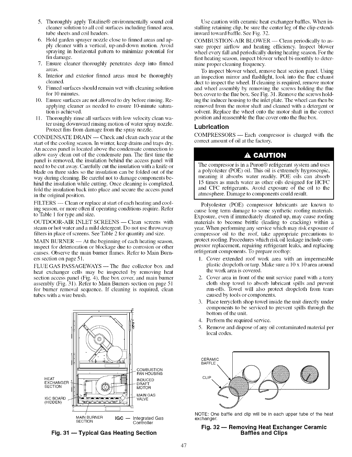
5. ThoroughlyapplyTot_dine®environmentallysoundcoil
cleanersolutiontoallcoilsurfacesincludingfinnedtuea,
tubesheetsandcoilheaders.
6. Holdgmdensprayernozzleclosetofinnedareasandap-
plycleanerwithavertical,up-and-downmotion.Avoid
sprayingin horizontalpatterntominimizepotenti_dfor
findamage.
7. Ensurecleanerthoroughlypenetratesdeepintofinned
areas.
8. Interiorandexteriorfinnedareasmustbethoroughly
cleaned.
9. Finnedsurfacesshouldremainwetwithcleaningsolution
for10minutes.
10.Ensuresurfacesarenotallowedtodinbeforerinsing.Re-
applyingcleanerasneededto ensure10-minutesatura-
tionisachieved.
11.Thoroughlyrinseallsurfaceswithlowvelocitycleanwa-
terusingdownwardrinsingmotionofwaterspraynozzle.
Protectfinsfl'om&imagefromthespraynozzle.
CONDENSATEDRAIN-- Checkandcleaneachyearatthe
startofthecoolingseason.Inwintel;keepdiainsandtrapsdiN.
Anaccesspanelislocatedabovethecondensateconnectionto
alloweasycleanoutofthecondensatepan.Thefirsttimethe
panelisremoved,theinsulationbehindtheaccesspanelwill
needtobecutaway.Carefullycuttheinsulationwithaknifeor
bladeonthreesidessotheinsulationcanbefoldedoutofthe
wayduringcleaning.Becarefulnotto &image components be-
hind the insulation while cutting. Once cleaning is completed,
fold the insulation back into place and secure the access panel
in the original position.
FILTERS -- Clean or replace at start of each heating and cool-
ing season, or more often if operating conditions require. Refer
to Table 1 for type and size.
OUTDOOR-AIR INLET SCREENS -- Clean screens with
steam or hot water and a mild detergent. Do not use throwaway
filters in place of screens. See Table 2 for quantity and size.
MAIN BURNER -- At the beginning of each heating season,
inspect for deterioration or blockage due to conosion or other
causes. Observe the main burner flmnes. Refer to Main Burn-
ers section on page 51.
FLUE GAS PASSAGEWAYS -- The flue collector box and
heat exchanger cells may be inspected by removing heat
section access panel (Fig. 4), flue box cover, and main burner
assembly (Fig. 31). Refer to Main Burners section on page 51
for burner removed sequence. If cleaning is required, clean
tubes with a wire brush.
HEAT
EXCHANGER -
SECTION
IGC BOARD /
(HIDDEN)
1:
COMBUSTION
FAN HOUSING
INDUCED
DRAFT
MOTOR
MAIN BURNER IGC -- Integrated Gas
SECTION Controller
MAIN GAS
VALVE
Fig. 31 -- Typical Gas Heating Section
Use c_mtion with ceramic heat exchanger baffles. When in-
stalling retaining clip, be sure the center leg of the clip extends
inw_ud toward baffle. See Fig. 32.
COMBUSTION-AIR BLOWER -- Clean periodically to as-
sure proper aidlow and heating efficiency. Inspect blower
wheel every fall and periodic_dly during heating season. For the
first heating season, inspect blower wheel bi-monthly to deter-
mine proper cleaning frequency.
To inspect blower wheel, remove heat section panel. Using
tm inspection minor and flashlight, look into the flue exhaust
duct to inspect the wheel. If cleaning is required, remove motor
and wheel assembly by removing the screws holding the flue
box cover to the flue box. See Fig. 31. Remove the screws hold-
ing the inducer housing to the inlet plate. The wheel can then be
removed from the motor shall and cleaned with a detergent or
solvent. Replace the wheel onto the motor shall in the con'ect
position and reassemble the flue cover onto the flue box.
Lubrication
COMPRESSORS iEach compressor is charged with the
correct amount of oil at the factory.
The compressor is in a Puron® re ftigerant system and uses
a polyolester (POE) oil. This oil is extremely hygroscopic,
meaning it absorbs water readily. POE oils can absorb
15 times as much water as other oils designed for HCFC
and CFC refrigerants. Avoid exposure of the oil to the
atmosphere. Damage to components could result.
Polyolester (POE) compressor lubricants are known to
cause long term dmnage to some synthetic roofing materials.
Exposure, even if immediately cleaned up, may cause roofing
materials to become brittle (leading to cracking) within a
yeac When performing any service which may risk exposure of
compressor oil to the roof. take appropriate precautions to
protect roofing. Procedures which risk oil leakage include com-
pressor replacement, repairing refrigerant leaks, and replacing
refrigerant components. To prepare rooftop:
1. Cover extended roof work area with an impermeable
plastic dropcloth or ttup. Make sure a 10 x 10 tuea around
the work area is covered.
2. Cover area in front of the unit service panel with a terry
cloth shop towel to absorb lubricant spills and prevent
mn-of£s. Towel will also protect diopcloth flom te;us
caused by tools or components.
3. Place terrycloth shop towel inside the unit directly under
components to be serviced to prevent spills through the
bottom of the unit.
4. Perform the lequired service.
5. Remove and dispose of tiny oil contaminated material per
local codes.
CERAMIC
BAFFLE
CLIP __
NOTE: One baffle and clip will be in each upper tube of the heat
exchanger.
Fig. 32 1Removing Heat Exchanger Ceramic
Baffles and Clips
47
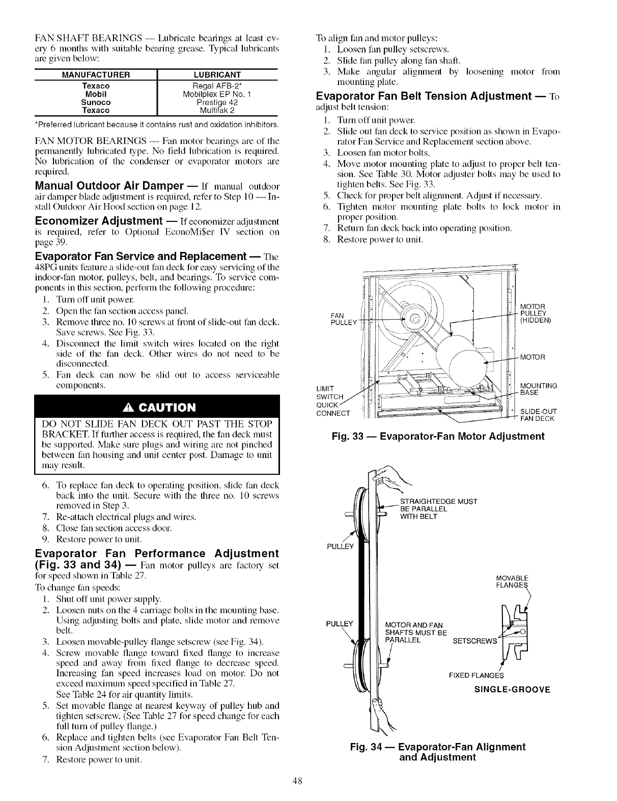
FAN SHAFT BEARINGS -- Lubricate beatings at least ev-
ely 6 months with suitable betuing grease. Typical lubricants
ale given below:
MANUFACTURER I
Texaco
Mobil
Surloco
Texaco
*Preferred lubricant because it contains rust and oxidation inhibitors.
LUBRICANT
Regal AFB-2*
Mobilplex EP No, 1
Prestige 42
Multifak 2
FAN MOTOR BEARINGS -- Fan motor bearings me of the
permanently lubricated type. No field lubrication is required.
No lubrication of the condenser or evaporator motors me
required.
Manual Outdoor Air Damper-- If manual outdoor
air &unper blade adjustment is required, refer to Step 10 -- In-
st;dl Outdoor Air Hood section on page 12.
Economizer Adjustment -- If economizer adjustment
is requiled, refer to Optional EconoMiSer IV section on
page 39.
Evaporator Fan Service and Replacement -- The
48PG units feature a slide-out fan deck for easy servicing of the
indoor-fan motol: pulleys, belt, and bearings. To service com-
ponents in fltis section, perform the following procedure:
1. Turn off unit powel:
2. Open the fan section access panel.
3. Remove three no. 10 screws at front of slide-out fan deck.
Save screws. See Fig. 33.
4. Disconnect the limit switch wires located on the right
side of the fan deck. Other wires do not need to be
disconnected.
5. Fan deck can now be slid out to access serviceable
components.
DO NOT SLIDE FAN DECK OUT PAST THE STOP
BRACKET. If further access is required, the fan deck must
be supported. Make sure plugs and wiring are not pinched
between fan housing and unit center post. Dmnage to unit
may result.
To align fan and motor pulleys:
1. Loosen fan pulley setscrews.
2. Slide fan pulley ;dong fan shaft.
3. Make angular alignment by loosening motor fiom
mounting plate.
Evaporator Fan Belt Tension Adjustment -- To
adjust belt tension:
1. Turn offunit powel:
2. Slide out fan deck to service position as shown in Evapo-
rator Fan Service and Replacement section above.
3. Loosen fan motor bolts.
4. Move motor mounting plate to adjust to proper belt ten-
sion. See Table 30. Motor adjuster bolts may be used to
tighten belts. See Fig. 33.
5. Check for proper belt _flignment.Adjust if necess_uy.
6. Tighten motor mounting plate bolts to lock motor in
proper position.
7. Return fan deck back into operating position.
8. Restore power to unit.
MOTOR
FAN _ PULLEY
PULLEY (HIDDEN)
MOTOR
MOUNTING
LIMIT ÷ BASE
SWITCH
CONNECT SLIDE-OUT
FAN DECK
Fig. 33 -- Evaporator-Fan Motor Adjustment
6. To replace fan deck to operating position, slide fan deck
back into the unit. Secure with the three no. 10 screws
removed in Step 3.
7. Re-attach electrical plugs and wires.
8. Close fan section access door.
9. Restore power to unit.
Evaporator Fan Performance Adjustment
(Fig. 33 and 34) -- Fan motor pulleys are factory set
for speed shown in Table 27.
To change fan speeds:
1. Shut off unit power supply.
2. Ix_osen nuts on the 4 carriage bolts in the mounting base.
Using adjusting bolts and plate, slide motor and remove
belt.
3. Ix_osen movable-pulley flange setscrew (see Fig. 34).
4. Screw movable flange toward fixed flange to increase
speed and away from fixed flange to decrease speed.
Increasing fan speed increases load on motol: Do not
exceed maximum speed specified in Table 27.
See Table 24 for air quantity limits.
5. Set movable flange at nearest keyway of pulley hub and
tighten setscrew. (See Table 27 for speed change for each
full turn of pulley flange.)
6. Replace and tighten belts (see Evaporator Fan Belt Ten-
sion Adjustment section below).
7. Restore power to unit.
PULLEY
PULLEY
STRAIGHTEDGE MUST
WITH BELT
MOTOR AND FAN
SHAFTS MUST BE
PARALLEL
MOVABLE
FLANGES
SETSCREWS
FIXED FLANGES
SINGLE-GROOVE
Fig. 34-- Evaporator-Fan Alignment
and Adjustment
48
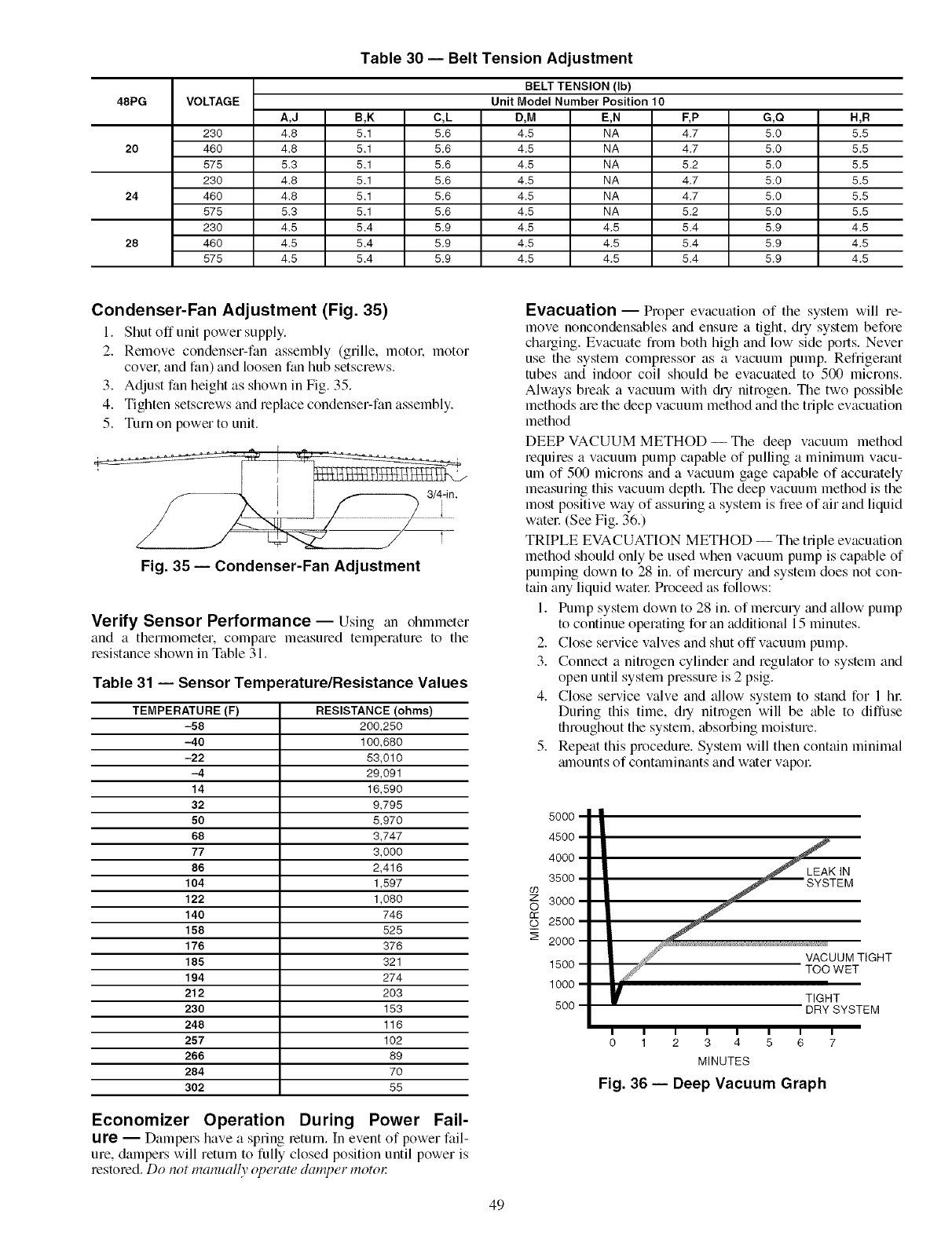
Table 30 -- Belt Tension Adjustment
BELT TENSION (Ib)
48PG VOLTAGE Unit Model Number Position 10
A,J B,K C,L D,M E,N F,P G,Q H,R
230 4.8 5.1 5.6 4.5 NA 4.7 5.0 5.5
20 460 4.8 5.1 5.6 4.5 NA 4.7 5.0 5.5
575 5.3 5.1 5.6 4.5 NA 5.2 5.0 5.5
230 4.8 5.1 5.6 4.5 NA 4.7 5.0 5.5
24 460 4.8 5.1 5.6 4.5 NA 4.7 5.0 5.5
575 5.3 5.1 5.6 4.5 NA 5.2 5.0 5.5
230 4.5 5.4 5.9 4.5 4.5 5.4 5.9 4.5
28 460 4.5 5.4 5.9 4.5 4.5 5.4 5.9 4.5
575 4.5 5.4 5.9 4.5 4.5 5.4 5.9 4.5
Condenser-Fan Adjustment (Fig. 35)
I. Shut off unit power supply.
2. Remove condenser-fan assembly (grille, motol: motor
covek and fan) and loosen fan hub setscrews.
3. Adjust fan height as shown in Fig. 35.
4. Tighten setscrews and replace condenser-fan assembly.
5. Turn on power to unit.
Fig. 35 -- Condenser-Fan Adjustment
Verify Sensor Performance -- Using an ohmmeter
and a thermometer, compme measured temperature to the
resistance shown in Table 31.
Table 31 -- Sensor Temperature/Resistance Values
TEMPERATURE (F) RESISTANCE (ohms)
-58 200,250
-40 100,680
-22 53,010
-4 29,091
14 16,590
32 9,795
50 5,970
68 3,747
77 3,000
86 2,416
104 1,597
122 1,080
140 746
158 525
176 376
185 321
194 274
212 203
230 153
248 116
257 102
266 89
284 70
302 55
Economizer Operation During Power Fail-
ure -- Dampers have a spring return. In event of power fail-
ure, dampers will return to fully closed position until power is
restored. Do not manually ol)emte damper motol:
Evacuation -- Proper evacuation of the system will re-
move noncondensables and ensure a tight, dry system before
charging. Evacuate from both high and low side ports. Never
use the system compressor as a vacuum pump. Refrigerant
tubes and indoor coil should be evacuated to 500 microns.
Always break a vacuum with @ nitrogen. The two possible
methods are the deep vacuum method and the triple evacuation
method
DEEP VACUUM METHOD-- The deep vacuum method
requires a vacuum pump capable of pulling a minimum vacu-
um of 500 microns and a vacuum gage capable of accurately
measuring this vacuum depth. The deep vacuum method is the
most positive way of assuring a system is free of air and liquid
watel: (See Fig. 36.)
TRIPLE EVACUATION METHOD -- The triple evacuation
method should only be used when vacuum pump is capable of
pumping down to 28 in. of mercu Uand system does not con-
tain any liquid watel: Proceed as follows:
1. Pump system down to 28 in. of mercury and allow pump
to continue operating for an additional 15 minutes.
2. Close service valves and shut off vacuum pump.
3. Connect a nitrogen cylinder and regulator to system and
open until system pressure is 2 psig.
4. Close service valve and allow system to stand for 1 hi:
During this time, dqnitrogen will be able to diffuse
throughout the system, absorbing moisture.
5. Repeat this procedure. System will then contain minimal
mnounts of contmninants and water vapol:
09
Z
O
rr
Q)
LEAK IN
VACUUM TIGHT
TOO WET
TIGHT
DRY SYSTEM
O 1 2 3 4 5 6 7
MINUTES
Fig. 36 -- Deep Vacuum Graph
49
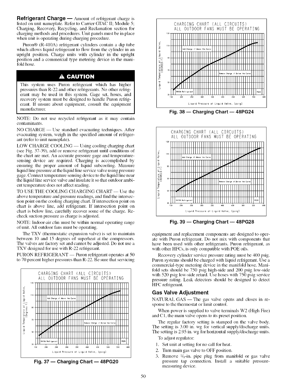
Refrigerant Charge -- Amount of refrigerant chmge is
listed on unit nameplate. Refer to Carrier GTAC II; Module 5;
Charging, Recovery. Recycling, and Reclamation section for
charging methods and procedures. Unit panels must be in place
when unit is operating during chm'ging procedme.
Puron® (R-410A) refrigerant cylinders contain a dip tube
which allows liquid refrigerant to flow from the cylinder in an
upright position. Charge units with cylinder in the upright
position and a commercial type metering device in the mani-
fold hose.
This system uses Puron refrigerant which has higher
pressmes than R-22 and other refrigerants. No other refrig-
erant may be used in this system. Gage set, hoses, and
recovery system must be designed to handle Puron refrig-
erant. If unsure about equipment, consult the equipment
manu facture_:
NOTE: Do not use recycled refrigerant as it may contain
contaminants.
NO CHARGE -- Use stan&trd evacuating techniques. After
evacuating system, weigh in the specified amount of refriger-
ant (refer to unit nameplate).
LOW CHARGE COOLING -- Using cooling charging chm-t
(see Fig. 37-39), add or remove refrigerant until conditions of
the chart me met. An accurate pressure gage and temperature-
sensing device are required. Charging is accomplished by
ensuring the proper amount of liquid subcooling. Measure
liquid line plessure at the liquid line service valve using pressure
gage. Connect temperature sensing device to the liquid line near
the liquid line service valve and insulate it so that outdoor mnbi-
ent temperatme does not affect leading.
TO USE THE COOLING CHARGING CHART -- Use the
above temperature and pressure readings, and find the intersec-
tion point on the cooling charging chart. If inteLsection point on
chart is above line, add refrigerant. If intersection point on
chart is below line, cmefully recover some of the charge. Re-
check suction pressure as chmge is adjusted.
NOTE: Indoor-air cfin must be within normal operating range
of unit. All outdoor fans must be operating.
The TXV (thermostatic expansion v_flve) is set to maintain
between 10 and 15 degrees of superheat at the compressors.
The v_dves are factory set and cannot be adjusted. Do not use a
TXV designed for use with R-22 refrigerant.
PURON REFRIGERANT -- Puron refrigerant operates at 50
to 70 percent higher pressmes than R-22. Be sure that servicing
CHARGING CHART (ALL CIRCUITS)
ALL OUTDOOR FANS MUST BE OPERATING
Liquid Pressure a_ Liquid Valve, [p_igl
Fig. 37 -- Charging Chart -- 48PG20
Fig. 39 -- Charging Chart -- 48PG28
equipment and replacement components am designed to oper-
ate with Puron refrigerant. Do not mix with components that
have been used with other refrigerants. Puron refrigerant, as
with other HFCs, is only compatible with POE oils.
Recove Ucylinder service pressure rating must be 400 psig.
Puron systems should be charged with liquid refrigerant. Use a
commercial-type metering device in the manifold hose. Mani-
fold sets should be 750 psig high-side and 200 psig low-side
with 520 psig low-side mtmd. Use hoses with 750 psig service
pressure rating. Leak detectors should be designed to detect
HFC refrigerant.
Gas Valve Adjustment
NATURAL GAS- The gas valve ()pens and closes in re-
sponse to the thermostat or limit control.
When power is supplied to valve terminals W2 (High Fire)
and C l, the main valve opens to its preset position.
The regular factory setting is stmnped on the valve body.
The setting is 3.00 in. wg for vertical supply/discharge units.
The setting is 2.95 in. wg for horizont_d supply/discharge units.
To adjust regulator:
1. Set unit at setting for no call for heat.
2. Turn main gas valve to OFF position.
3. Remove l/s-in, pipe plug from manifold or gas valve
pressure tap connection. Install a suitable p_essure-
measuring device.
5O
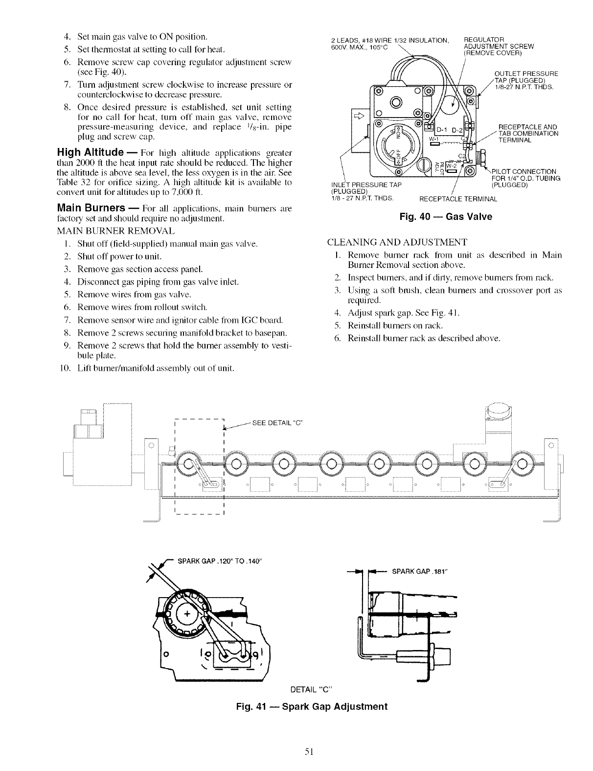
4. SetmaingasvalvetoONposition.
5. Setthennostatatsettingtocallforheat.
6. Removescrewcapcoveringregulatoradjustmentsclew
(seeFig.40).
7. Turnadjustmentscrewclockwisetoincreasepressureor
counterclockwisetodecreasepressure.
8. Oncedesiredpressureisestablished,setunitsetting
fornocallforheat,turnoffmaingasvalve,remove
pressure-measuringdevice,andreplaceI/s-in.pipe
plugandscrewcap.
High Altitude--For high altitude applications greater
than 2000 ft the heat input rate should be reduced. The higher
the altitude is above sea level, the less oxygen is in the all: See
Table 32 for orifice sizing. A high ;fltitude kit is available to
convert unit for altitudes up to 7,000 ft.
Main Burners -- For all applications, main burners are
factory set and should require no adjustment.
MAIN BURNER REMOVAL
1. Shut off (field-supplied) manual main gas valve.
2. Shut off power to unit.
3. Remove gas section access panel.
4. Disconnect gas piping from gas valve inlet.
5. Remove wires from gas valve.
6. Remove wires from rollout switch.
7. Remove sensor wire and ignitor cable from [GC board.
8. Remove 2 screws securing manifold bracket to basepan.
9. Remove 2 screws that hold the burner assembly to vesti-
bule plate.
10. Lift burner/manifold assembly out of unit.
2 LEADS, #18 WIRE 1/32 INSULATION,
600V. MAX.,
(PLUGGED) /
1/8 - 27 N.P.q_ THDS.
REGULATOR
ADJUSTMENT SCREW
REMOVE COVER)
OUTLET PRESSURE
/'TAP (PLUGGED)
i jl/8-27 N.P.]_ THDS.
RECEPTACLE AND
J TAB COMBINATION
TERMINAL
_", PI LOT CONNECTION
FOR 1/4" O.D. TUBING
(PLUGGED)
RECEPTACLE TERMINAL
Fig. 40 -- Gas Valve
CLEANING AND ADJUSTMENT
1. Remove burner rack from unit as described in Main
Burner Removal section above.
2. Inspect burners, and if dirty, remove burners from rack.
3. Using a soft brash, clean burnel_ and crossover port as
required.
4. Adjust spark gap. See Fig. 41.
5. Reinstall burners on rack.
6. Reinstall burner rack as described above.
I _ SEE DETAIL "C"
I I [............................
I I ,I I <-_
,_ _ _ ...... i x _'_
°"1 .....................,[ ,, ...............i, .............i .... I l
I I
, ,
SPARK GAP.12ff'TO.140"
_._RK GAP .181"
I1 ,_2 -
DETAIL "C"
Fig. 41 -- Spark Gap Adjustment
51
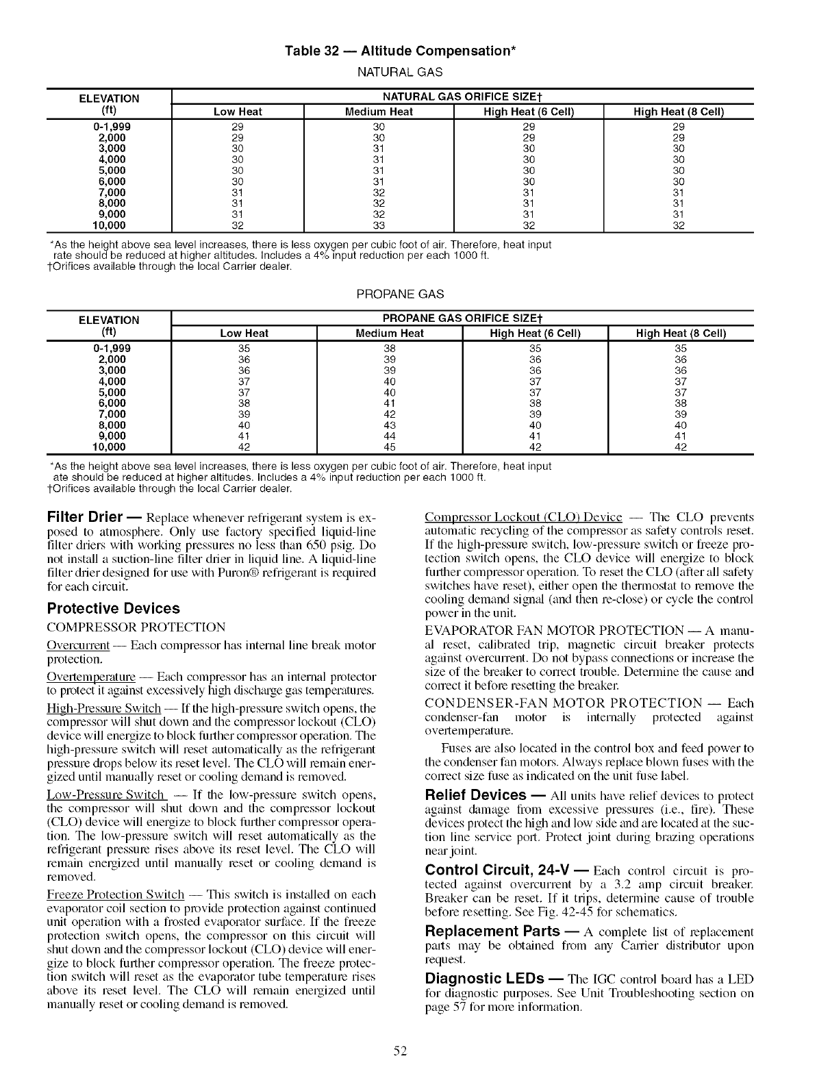
Table 32 -- Altitude Compensation*
NATURALGAS
ELEVATION
(ft)
0-1,999
2,000
3,000
4,000
5,000
6,000
7,000
8,000
9,000
10,000
Low Heat
29
29
3O
3O
3O
3O
31
31
31
32
NATURAL GAS ORIFICE SIZEt
Medium Heat High Heat (6 Cell)
3O
3O
31
31
31
31
32
32
32
33
29
29
30
30
30
30
31
31
31
32
High Heat (8 Cell)
29
29
30
30
30
30
31
31
31
32
*As the height above sea level increases, there is less oxygen per cubic foot of air. Therefore, heat input
rate should be reduced at higher altitudes. Includes a 4% input reduction per each 1000 ft.
1-Orifices available through the local Carrier dealer.
PROPANE GAS
PROPANE GAS ORIFICE SIZEt
Low Heat Medium Heat High Heat (6 Cell)
ELEVATION
(ft)
0-1,999
2,000
3,000
4,000
5,000
6,000
7,000
8,000
9,000
10,000
35
36
36
37
37
38
39
4O
41
42
38
39
39
4O
4O
41
42
43
44
45
35
36
36
37
37
38
39
4O
41
42
High Heat (8 Cell)
35
36
36
37
37
38
39
40
41
42
*As the height above sea level increases, there is less oxygen per cubic foot of air. Therefore, heat input
ate should be reduced at higher altitudes. Includes a 4% input reduction per each 1000 ft.
1-Orifices available through the local Carrier dealer.
Filter Drier -- Replace whenever refi'igerant system is ex-
posed to atmosphere. Only use factory specified liquid-line
filter driers with working pressures no less than 650 psig. Do
not install a suction-line filter drier in liquid line. A liquid-line
filter drier designed for use with Puron® refi'igerant is required
for each circuit.
Protective Devices
COMPRESSOR PROTECTION
Overcurrent -- Each compressor has internal line break motor
protection.
Overtemperature -- Each compressor has an internal protector
to protect it ag_dnst excessively high dischmge gas temperatures.
High-Pressure Switch --If the high-pressure switch opens, the
compressor will shut down trod the compressor lockout (CLO)
device will energize to block further compressor operation. The
high-pressure switch will reset automatically as the refrigerant
pressure &ops below its reset level. The CLO will lem_dn ener-
gized until manually reset or cooling demand is removed.
Low-Pressure Switch -- If the low-pressure switch opens,
the compressor will shut down and the compressor lockout
(CLO) device will energize to block further compressor opera-
tion. The low-pressure switch will reset automatically as the
refrigerant pressure rises above its reset level. The CLO will
remain energized until manually reset or cooling demand is
removed.
Freeze Protection Switch -- This switch is inst_dled on each
evaporator coil section to provide protection against continued
unit operation with a frosted evaporator surface. [f the freeze
protection switch opens, the compressor on this circuit will
shut down and the compressor lockout (CLO) device will ener-
gize to block further compressor operation. The freeze protec-
tion switch will reset as the evaporator tube temperature rises
above its reset level. The CLO will remain energized until
manually reset or cooling demand is removed.
Compressor Lockout (CLO)Device -- The CLO prevents
automatic recycling of the compressor as safety controls leset.
If the high-pressme switch, low-pressure switch or freeze pro-
tection switch opens, the CLO device will energize to block
further compressor operation. To reset the CLO (after all safety
switches have reset), either open the thermostat to remove the
cooling demand signal (and then re-close) or cycle the control
power in the unit.
EVAPORATOR FAN MOTOR PROTECTION -- A manu-
al reset, calibrated trip, magnetic circuit breaker protects
against overcurrent. Do not bypass connections or increase the
size of the breaker to correct trouble. Determine the cause and
correct it befole resetting the breakel:
CONDENSER-FAN MOTOR PROTECTION -- Each
condenser-fan motor is internally protected against
overtemperatme.
Fuses me also located in the control box and feed power to
the condenser fan motors. Always replace blown fuses with the
conect size fuse as indicated on the unit fuse label.
Relief Devices -- All units have relief devices to protect
against &image from excessive pressures (i.e., fire). These
devices protect the high and low side and are located at the suc-
tion line sel-vice port. Protect joint during brazing operations
ne_u joint.
Control Circuit, 24-V- Each control circuit is pro-
tected against overcurrent by a 3.2 amp circuit breakel:
Breaker can be reset. [f it trips, determine cause of trouble
before resetting. See Fig. 42-45 for schematics.
Replacement Parts -- A complete list of replacement
parts may be obtained from any Career distributor upon
request.
Diagnostic LEDs -- The [GC control board has a LED
for diagnostic purposes. See Unit Troubleshooting section on
page 57 for mole information.
52
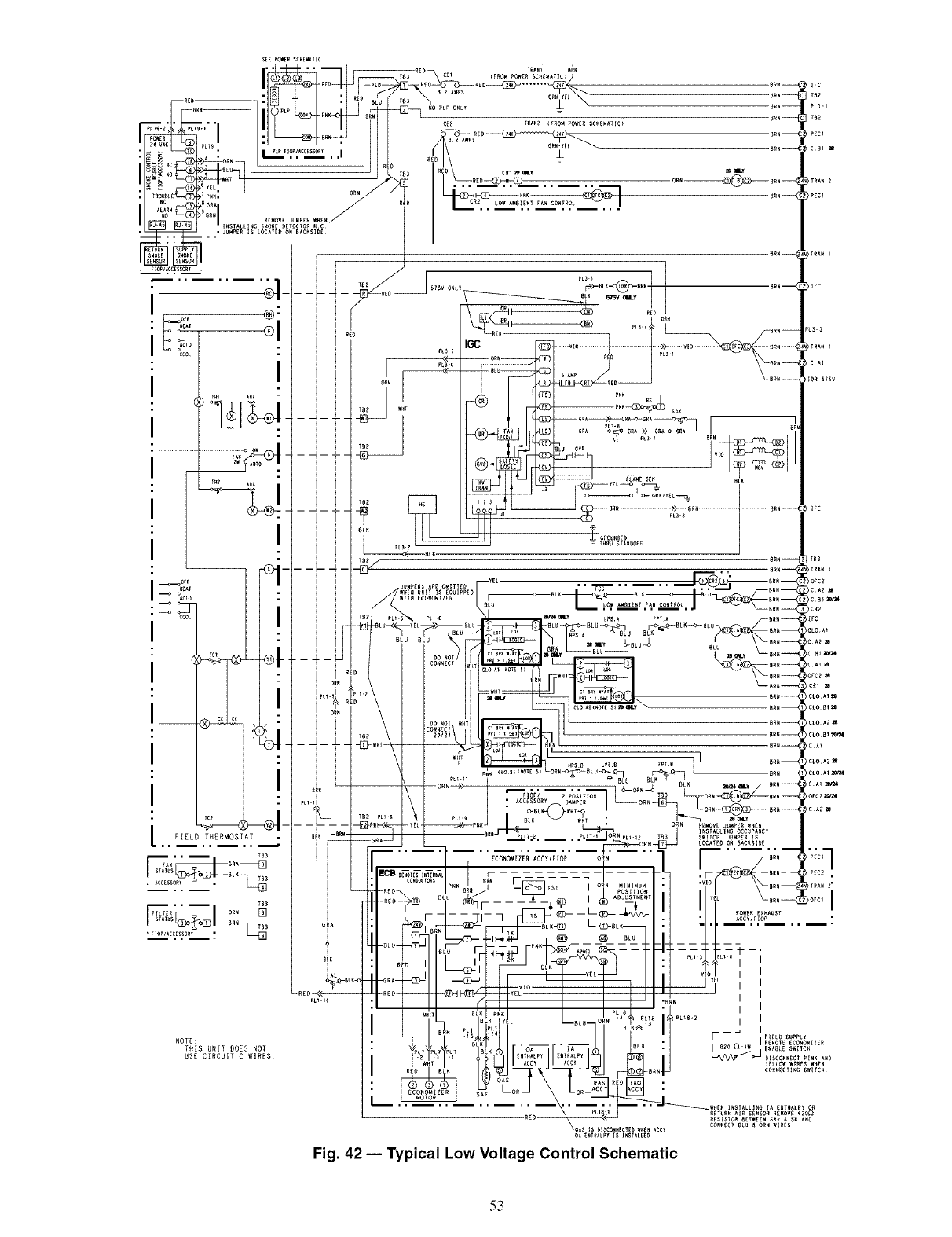
:®
I
I
IGC
53
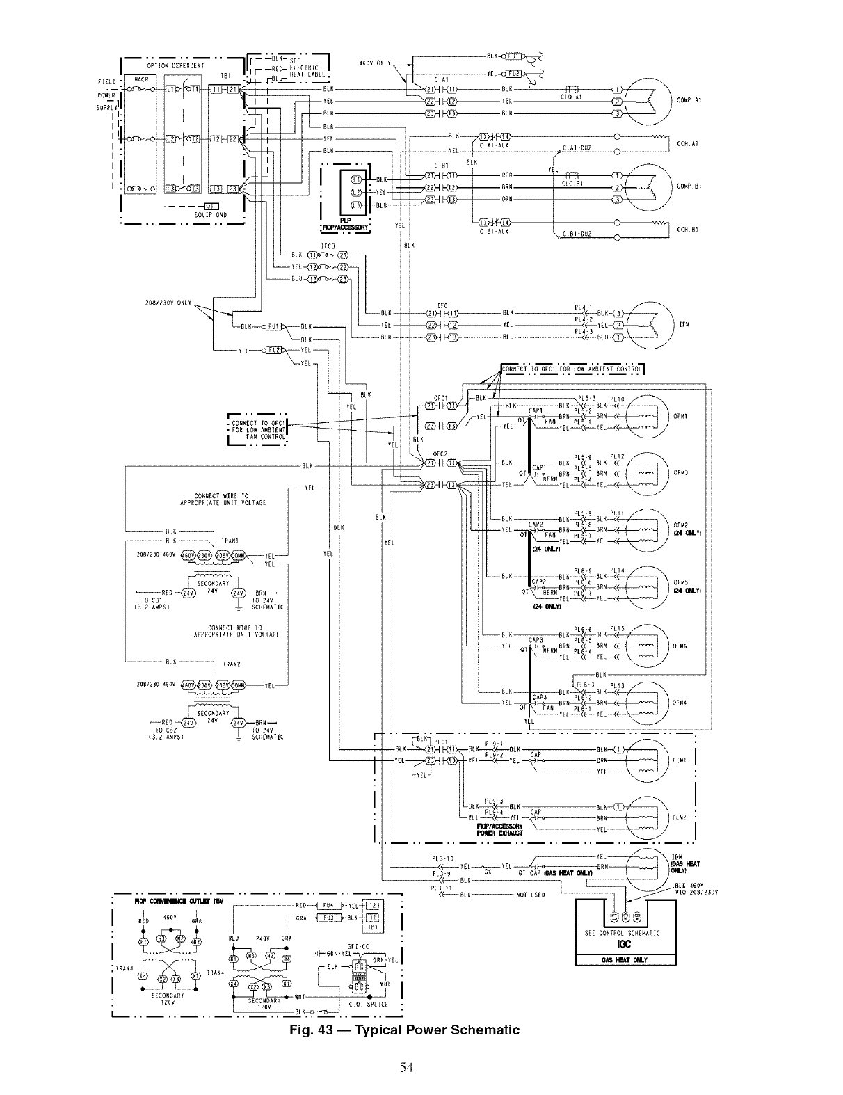
[
[
EQUIP GND
208/Z30V
CORNECT WIRE TO F_]YEL
APPROPRIATE UNIT VOLTAGE
RLK
--RL_ TRAN1
_RER_BR_TO CRI TO _4V
IR_R AMPR/ _ CHEHATIE
CONNECT FIRE TO
APPROPRIATE URIT VOLTAGE
OFCR
ROP (X_ Ot_ IISV
RID 4SOY I
GRA
SECONDARY
: 120v
L
COMP A1
ORMI
OFM3
Fig. 43 -- Typical Power Schematic
54
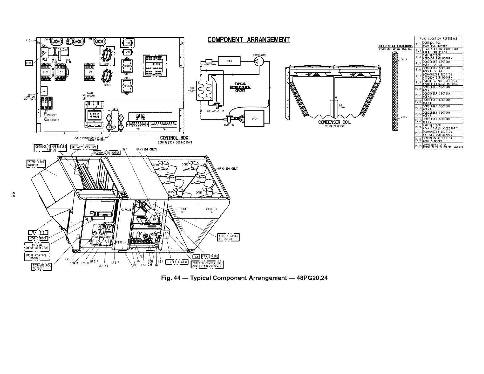
OB TD()OR TEMPERATURE
AND AL
r
su_
COOLER
I................J.,
CONI'ROL BOX
CONPRESSOR CONTACTORG
COMPONENT ARRANGEMENT
C_PRESSO_
CONDB_SB_ COIL
PLUG LOCATION RZFERERCZ
CONTROL BOX
RREEB£STAT LO(_A'nONS (CONTROL BOARD}
EVaPOratOR_E_R_ B_E_ iRE 3HEAT SZGT]O_ PARTITIOR
zo_z_ (HEAT CONTROLS}
FAN SECTION
(IND(_)R FAN MOTOR)
_ONDE_SER SECTION
(OFMI. 2, 3]
_ONDE_SER SECTION
(OFM4, 5, 6)
PL_ ECONOMIZER D_CTION
(ECOffOMIEER MOTOR)
ipL R POWER EXHAUST GECTIOR
IPOW_R EXHAUST _OTORS}
CONDERS£R SECTION
(OFMI)
_ONDENSER SECTION
(OFMB)
CONDENSER SECTION
(OF_3)
_ONDE_SER SECTION
(OFM4}
_LI4 _ONDE_SER SECTION
(OFMS}
CONDenSER SECTION
(OFM6)
FAN SECTION
(FAN STATUS ACCESSORY)
ECONOMIZER SECTION
(2-POSITION DAMPER)
EO_PRESDOR SECTION
(CO_ SENSOR)
iPL19:_PeESSOeSECT_O_
L_
CIRCUIT
B
•SMO_E DETECTOR
SMO_E CORTROL:
CCHDI
CCHAI
LPSA
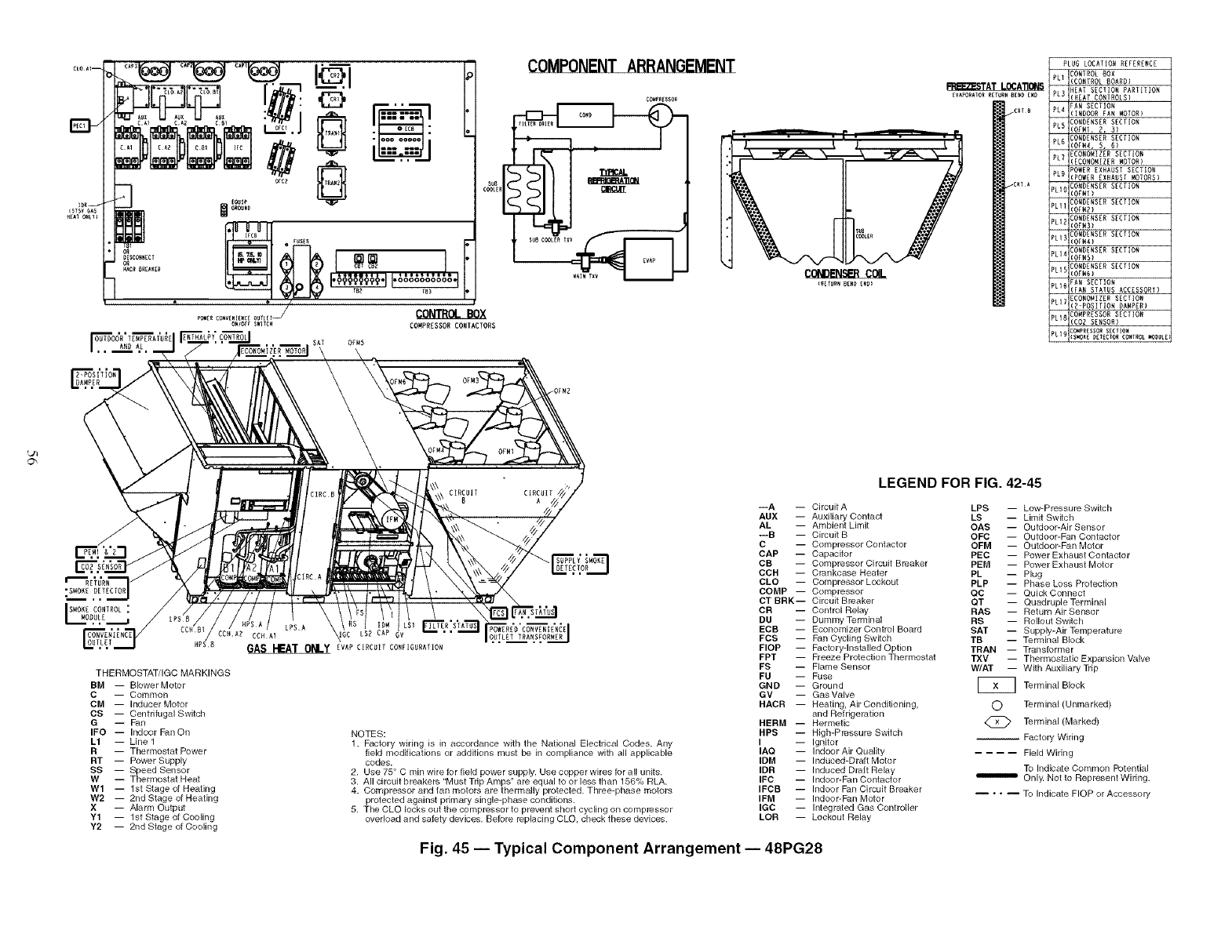
PLUG LOCATION REFERENCE
PLI CONTROL _OX
(CONTROL 80ADD}
HEAT SECTIO_ PARTITIO_
PL3 (HEAT CONTROLS}
RAN SECTION
PL4 (INDOOR FAN MOTOR}
CONDENSER SECTIO_
PLR (OE_1, 2, 31
PL6 CONDENSER SECTIO_
(OF_4, 5, 6)
ECONOMIZER SECTIO_
PLT (ECONOMIZER MOTOR)
POWER EXHAUST SECTIO_
PL9 (PO_ER EXHAUST MOTORS}
PLIU CONDENSER SECTIOR
(OF_1)
PL11 CONDENSER SECTIO_
(OF_2)
CONDENSER SECTIOR
PL12 IOE_3)
PL13 CONDENSER SECTIO_
(OF_4)
CONDENSER SECTION
PL14 IOF_5)
PLIE CONDENSER SECTIO_
(OF_R)
RAN SECTIO_
PlIR (FAN STATUS ACCESSORY)
ECONOMIZER UECT_O_
PL17 (R-POSITIO_ DAMPED1
PlIR COMPRESSOR SECTIO_
(COD SENSOR1
COmpReSSORSECTIO_
PL19 _S_OK_DET£CTORCONTROL_O_ULE
CIRCUIT
D
FI_,R'S_ATU'_ OUTLET TRA_SFO_CCHAR CCHA] ' '
HPSD GASHEAT ONLY ZVAP CIRCUIT CONFIGURATIOR
THERMOSTAT/IGC MARKINGS
BM -- BIowerMotor
C-- Common
CM -- Inducer Motor
CS -- Centrifugal Switch
G-- Fan
IFO -- Indoor Fan On
L1 -- Line 1
R-- Thermostat Power
RT -- Power Supply
SS -- Speed Sensor
W -- Thermostat Heat
W1 -- 1st Stage of Heating
W2 -- 2nd Stage of Heating
X-- Alarm Output
Y1 -- tst Stage of Cooling
Y2 -- 2rid Stage of Cooling
NOTES:
1. Factory wiring is in accordance with the National Electrical Codes. Any
field modifications or additions must be in compliance with all applicable
codes.
2. Use 75° C min wire for field power supply. Use copper wires for all units.
3. All circuit breakers "Must Trip Amps" are equal to or less than 156% RLA.
4. Compressor and fan motors are thermally protected. Three=phase motors
protected against primary single-phase conditions.
5. The CLO locks out the compressor to prevent short cycling on compressor
overload and safety devices. Before replacing CLO, check these devices.
---A --
AUX --
AL
---B --
C
CAP --
CB
CCH --
OLD --
COMP --
CT BRK-
CR
DU
ECB --
FCS --
FlOP --
FPT --
FS
FU
GND --
GV
HACR --
HERM --
HPS --
I
IAQ --
IDM --
IDR --
IFC --
IFCB --
IFM --
IGC --
LOR --
LEGEND FOR FIG. 42-45
Circuit A
Auxiliary Contact
Ambient Limit
Circuit B
Compressor Contactor
Capacitor
Compressor Circuit Breaker
Crankcase Heater
Compressor Lockout
Compressor
Circuit Breaker
Control Relay
Dummy Terminal
Economizer Control Board
Fan Cycling Switch
Factory-Installed Option
Freeze Protection Thermostat
Flame Sensor
Fuse
Ground
Gas Valve
Heating, Air Conditioning,
and Refrigeration
Hermetic
High-Pressure Switch
Ignitor
Indoor Air Quality
Induced=Draft Motor
Induced Draft Relay
Indoor=Fan Confacfor
Indoor Fan Circuit Breaker
Indoor=Fan Motor
Integrated Gas Controller
Lockout Relay
LPS -- Low-Pressure Switch
LS -- Limit Switch
OAS -- Outdoor-Air Sensor
OFC -- Outdoor-Fan Contactor
OFM -- Outdoor=Fan Motor
PEC -- Power Exhaust Contactor
PEM -- Power Exhaust Motor
PL -- Plug
PLP -- Phase Loss Protection
QC -- Quick Connect
QT -- Quadruple Terminal
RAS -- Return Air Sensor
RS -- Rollout Switch
SAT -- Supply-Air Temperature
TB -- Terminal Block
TRAN -- Transformer
TXV -- Thermostatic Expansion Valve
W/AT -- With Auxiliary Trip
Terminal Block
O Terminal (Unmarked)
@ Terminal (Marked)
-- Factory Wiring
.... Field Wiring
To Indicate Common Potential
m OnlF Notto Represent Widng.
.... To Indicate FlOP or Accessory
Fig. 45 -- Typical Component Arrangement -- 48PG28
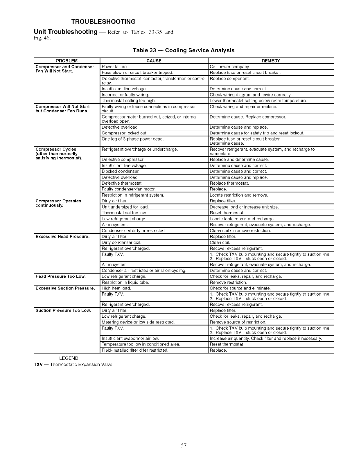
TROUBLESHOOTING
Unit Troubleshooting- Refer to Tables 33-35 and
Fig. 46.
Table 33 -- Cooling Service Analysis
PROBLEM CAUSE REMEDY
Compressor and Condenser Power failure. Gall power company.
Fan Will Not Start, Fuse blown or circuit breaker tripped. Replace fuse or reset circuit breaker.
Defective thermostat, contactor, transformer, or control Replace component.
relay.
Insufficient line voltage. Determine cause and correct.
Incorrect or faulty wiring. Check wiring diagram and rewire correctly.
Thermostat setting too high. Lower thermostat setting below room temperature.
Compressor Will Not Start Faulty wiring or loose connections in compressor Check wiring and repair or replace.
but Condenser Fan Runs. circuit.
Compressor motor burned out, seized, or internal Determine cause. Replace compressor.
overload open.
Defective overload. Determine cause and replace.
Compressor locked out Determine cause for safety trip and reset lockout.
One leg of 3-phase power dead. Replace fuse or reset circuit breaker.
Determine cause.
Compressor Cycles Refrigerant overcharge or undercharge. Recover refrigerant, evacuate system, and recharge to
(other than normally nameplate.
satisfying thermostat), Defective compressor. Replace and determine cause.
Insufficient line voltage. Determine cause and correct.
Blocked condenser. Determine cause and correct.
Defective overload. Determine cause and replace.
Defective thermostat. Replace thermostat.
Faulty condenser-fan motor. Replace.
Restriction in refrigerant system. Locate restriction and remove.
Compressor Operates Dirty air filter. Replace filter.
continuously. Unit undersized for load. Decrease load or increase unit size.
Thermostat set too low. Reset thermostat.
Low refrigerant charge. Locate leak, repair, and recharge.
Air in system. Recover refrigerant, evacuate system, and recharge.
Condenser coil dirty or restricted. Clean coil or remove restriction.
Excessive Head Pressure. Dirty air filter. Replace filter.
Dirty condenser coil. Clean coil.
Refrigerant overcharged. Recover excess refrigerant.
Faulty TXV. 1. Check TXV bulb mounting and secure tightly to suction line.
2. Replace TXV if stuck open or closed.
Air in system. Recover refrigerant, evacuate system, and recharge.
Condenser air restricted or air short-cycling. Determine cause and correct.
Head Pressure Too Low, Low refrigerant charge. Check for leaks, repair, and recharge.
Restriction in liquid tube. Remove restriction.
Excessive Suction Pressure. High heat load. Check for source and eliminate.
Faulty TXV. 1. Check TXV bulb mounting and secure tightly to suction line.
2. Replace TXV if stuck open or closed.
Refrigerant overcharged. Recover excess refrigerant.
Suction Pressure Too Low. Dirty air filter. Replace filter.
Low refrigerant charge. Check for leaks, repair, and recharge.
Metering device or low side restricted. Remove source of restriction.
Faulty TXV. 1. Check TXV bulb mounting and secure tightly to suction line.
2. Replace TXV if stuck open or closed.
Insufficient evaporator airflow. Increase air quantity. Check filter and replace if necessary.
Temperature too low in conditioned area. Reset thermostat.
Field-installed filter drier restricted. Replace.
LEGEND
TXV -- Thermostatic Expansion Valve
57
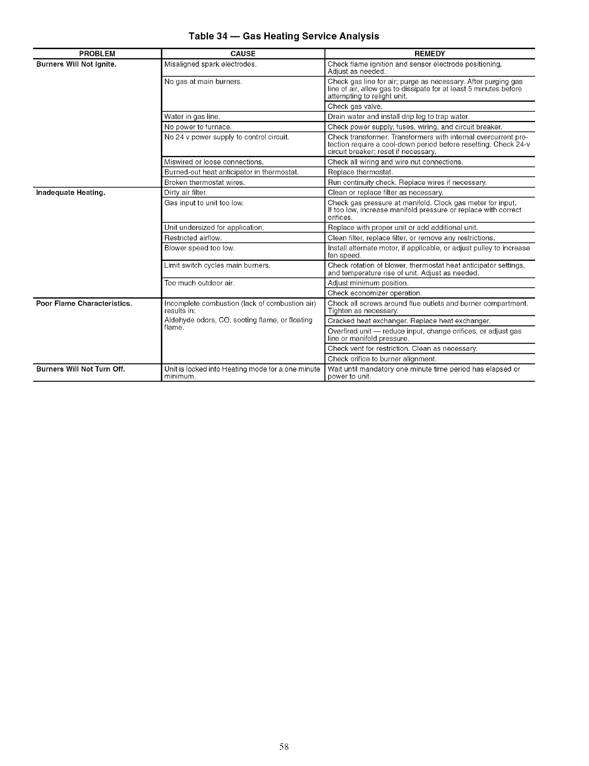
Table 34 -- Gas Heating Service Analysis
PROBLEM
Burners Will Not Ignite.
Inadequate Heating,
Poor Flame Characteristics.
Burners Will Not Turn Off.
CAUSE
Misaligned spark electrodes.
No gas at main burners.
Water in gas line.
No power to furnace.
No 24 v power supply to control circuit.
Miswired or loose connections.
Burned-out heat anticipator inthermostat.
Broken thermostat wires.
Dirty air filter.
Gas input to unit too low.
Unit undersized for application.
Restricted airflow.
Blower speed too low.
Limit switch cycles main burners.
Too much outdoor air.
Incomplete combustion (lack of combustion air)
results in:
Aldehyde odors, CO, sooting flame, or floating
flame.
Unit is locked into Heating mode for a one minute
minimum.
REMEDY
Check flame ignition and sensor electrode positioning.
Adjust as needed.
Check gas line for air; purge as necessary. After purging gas
line of air, allow gas to dissipate for at least 5 minutes before
attempting to relight unit.
Check gas valve.
Drain water and install drip leg to trap water.
Check power supply, fuses, wiring, and circuit breaker.
Check transformer. Transformers with internal overcurrent pro-
tection require a cool-down period before resetting. Check 24-v
circuit breaker; reset if necessary.
Check all wiring and wire nut connections.
Replace thermostat.
Run continuity check. Replace wires if necessary.
Clean or replace filter as necessary.
Check gas pressure at manifold. Clock gas meter for input.
If too low, increase manifold pressure or replace with correct
orifices.
Replace with proper unit or add additional unit.
Clean filter, replace filter, or remove any restrictions.
Install alternate motor, if applicable, or adjust pulley to increase
fan speed.
Check rotation of blower, thermostat heat anticipator settings,
and temperature rise of unit. Adjust as needed.
Adjust minimum position.
Check economizer operation.
Check all screws around flue outlets and burner compartment.
Tighten as necessary.
Cracked heat exchanger. Replace heat exchanger.
Overtired unit -- reduce input, change orifices, or adjust gas
line or manifold pressure.
Check vent for restriction. Clean as necessary.
Check orifice to burner alignment.
Wait until mandatory one minute time period has elapsed or
power to unit.
58
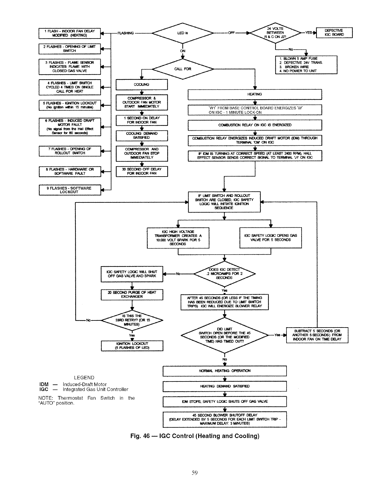
I 1 FLASH - _ FNq DELAY L=MO[Y_=IED (HE&TING) p--
I 2 _S -_ OF LIMIT
9ATICH
3 FLASHES -FLAIdE SE_NS(_
INI:_ATES _ V_H
CLOSED GAS VALVE
4_-UMIT 9PATCH
CYCLED 4 TIMES ON SINGLE
CALL FOR HEAT
I5_-IG_fi]ON LOCKOUT(No _v4htn 15 minutes)
6_-INDt.W3EDDRAFT
MOT(_ FAULT
(No _gnaJ _om _'_eH=_ B'_ct
Sensor for e0 second)
t 7_-_OF
ROtU3trr _
I , I
oLr_ FAN I_
,,_
,i I SECONO ON DELAY
bSAll-_
OUIIX)OR FAN STC_
'_MEDIATELY
30 S_D_OFF BY
'_ I FOR _NOOORFAN
I 9 FLASHES -SOFTWARELOCKOUT _'-
ON
I,BLOWN 5 AMP FUSE
2. (_=ECTNE 24V TRN_S.
3, BROKE_ V_RE
_1 4, NO POWER TO UNtT
t
I'Wl' FROM BASE CONTROL BOARD ENERGIZES 'W' ION IGC - I MINUTE LOCK-ON
I IF I_M IS _AT CORRE_f SPI_I) (AT LEAST 2400 RPI_, HALL I
E_'FECT S/_NSOR _'_DS _ _X:_AL TO TERMINAL *Jr' ON IGC
I
/
LOGIC V_LL INITIATE IGNITION
J
-I
HIGH VOLTAGE
CREATES A
10,000 "_)LT SPi_K FOR 5
8ECONOS
I
I _C S/_ET, fLOGIC V_LL _HUT
OFF GAS VALVE AND SPARK
EXCHANGER
Yes
(5 _ OF L_)
LEGEND
IDM -- Induced-Draft Motor
IGC -- Integrated Gas Unit Controller
NOTE: Thermostat Fan Switch in the
"AUTO" position.
I{GC S_ETY LOGIC OPENS GAS
VALVE FOR 5 5_-43OND8
I
Yes
I
IND_'_ FAN ON TIME DELAY
No
,i,
I _ sTc_,sA_-rYLC__ O__ V__V_ I
,I,
(DELAY EXTENDED BY 5 SECONDS FOR F-a_H UMIT SWfICH TRP -
MAXIMUM DELAY: 3 MINUTEB)
Fig. 46 -- IGC Control (Heating and Cooling)
.s9
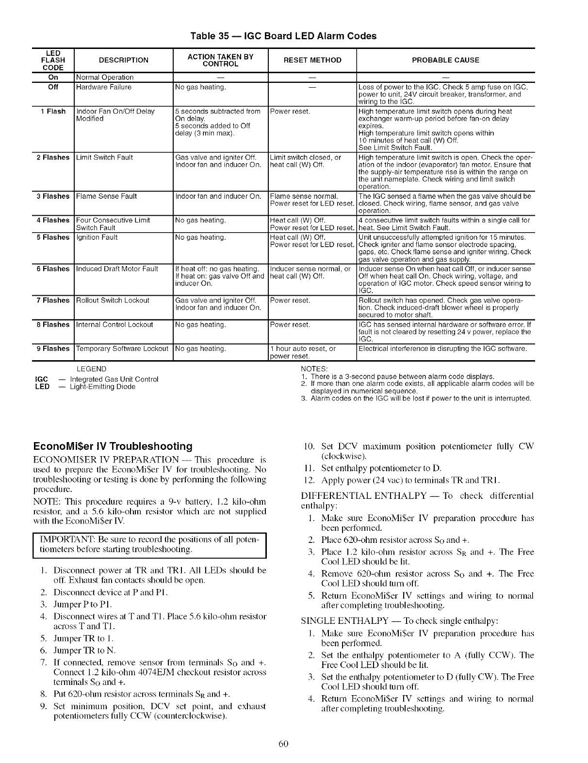
Table 35 -- IGC Board LED Alarm Codes
LED
FLASH
CODE
On
Off
1 Flash
2 Flashes
3 Flashes
4 Flashes
5 Flashes
6 Flashes
7 Flashes
8 Flashes
9 Flashes
DESCRIPTION
Normal Operation
Hardware Failure
Indoor Fan On/Off Delay
Modified
Limit Switch Fault
Flame Sense Fault
Four Consecutive Limit
Switch Fault
Ignition Fault
Induced Draft Motor Fault
Rollout Switch Lockout
Internal Control Lockout
Temporary Software Lockout
ACTION TAKEN BY
CONTROL
No gas heating,
5 seconds subtracted from
On delay.
5 seconds added to Off
delay (3 min max).
Gas valve and igniter Off.
Indoor fan and inducer On.
Indoor fan and inducer On.
No gas heating.
No gas heating.
If heat off: no gas heating.
If heat on: gas valve Off and
inducer On.
Gas valve and igniter Off.
Indoor fan and inducer On.
No gas heating,
No gas heating,
RESET METHOD
Power reset.
Limit switch closed, or
heat call (W) Off.
Flame sense normal.
Power reset for LED reset.
Heat call (W) Off.
Power reset for LED reset.
Heat call (W) Off.
Power reset for LED reset.
Inducer sense normal, or
heat call (W) Off.
Power reset.
Power reset.
hour auto reset, or
_owerreset.
PROBABLE CAUSE
Loss of power to the IGC. Check 5 amp fuse on IGC,
)ower to unit, 24V circuit breaker, transformer, and
wiring to the IGC.
High temperature limit switch opens during heat
exchanger warm-up period before fan-on delay
expires.
High temperature limit switch opens within
10 minutes of heat call (W) Off.
See Limit Switch Fault.
High temperature limit switch is open. Check the oper-
ation of the indoor (evaporator) fan motor. Ensure that
the supply-air temperature rise is within the range on
the unit nameplate. Check wiring and limit switch
operation.
The IGC sensed a flame when the gas valve should be
closed. Check wiring, flame sensor, and gas valve
operation.
4 consecutive limit switch faults within a single call for
heat. See Limit Switch Fault.
Unit unsuccessfully attempted ignition for 15 minutes.
Check igniter and flame sensor electrode spacing,
gaps, etc. Check flame sense and igniter wiring. Check
gas valve operation and gas supply.
Inducer sense On when heat call Off, or inducer sense
Off when heat call On. Check wiring, voltage, and
operation of IGC motor. Check speed sensor wiring to
IGC.
Rollout switch has opened. Check gas valve opera-
tion. Check induced-draft blower wheel is properly
secured to motor shaft.
IGC has sensed internal hardware or software error. If
fault is not cleared by resetting 24 v power, replace the
IGC.
Electrical interference is disrupting the IGC software.
LEGEND
IGC i Integrated Gas Unit Control
LED i Light-Emitting Diode
NOTES:
1. There is a 3-second pause between alarm code displays.
2. If more than one alarm code exists, all applicable alarm codes will be
displayed in numerical sequence.
3. Alarm codes on the IGC will be lost if power to the unit is interrupted.
EconoMi$er IV Troubleshooting
ECONOM[$ER IV PREPARATION -- This procedure is
used to prepare the EconoMiSer IV for troubleshooting. No
troubleshooting or testing is done by performing the following
procedure.
NOTE: This procedure requires a 9-v battery, 1.2 kilo-ohm
resistol, and a 5.6 kilo-ohm resistor which are not supplied
with the EconoMiSer IV.
IIMPORTANT: Be sure to record the positions of all poten - ]
tiometers before starting troubleshooting.
1. Disconnect power at TR and TRI. All LEDs should be
off. Exhaust fan contacts should be open.
2. Disconnect device at P and PI.
3. JumperPtoPl.
4. Disconnect wires at T and TI. Place 5.6 kilo-ohm resistor
across T and TI.
5. Jumper TR to 1.
6. Jumper TR to N.
7. If connected, remove sensor from terminals So and +.
Connect 1.2 kilo-ohm 4074EJM checkout resistor across
terminals So and +.
8. Put 620-ohm resistor across terminals SR and +.
9. Set minimum position, DCV set point, and exhaust
potentiometers fully CCW (counterclockwise).
10. Set DCV maximum position potentiometer fully CW
(clockwise).
11. Set enthalpy potentiometer to D.
12. Apply power (24 vac) to termimds TR and TRI.
DIFFERENTIAL ENTHALPY-- To check differential
enthalpy:
1. Make sure EconoMiSer IV prepmation procedure has
been performed.
2. Place 620-ohm resistor across So and +.
3. Place 1.2 kilo-ohm resistor across SR and +. The Free
Cool LED should be lit.
4. Remove 620-ohm resistor across So and +. The Free
Cool LED should turn off.
5. Return EconoMiSer IV settings and wiring to norm_d
after completing troubleshooting.
SINGLE ENTHALPY -- To check single enth_dpy:
1. Make sure EconoMi$er IV prepmation procedure has
been performed.
2. Set the enthalpy potentiometer to A (fully CCW). The
Free Cool LED should be lit.
3. Set the enthalpy potentiometer to O (fully CW). The Free
Cool LED should turn off.
4. Return EconoMiSer [V settings and wiring to normJ
after completing troubleshooting.
60
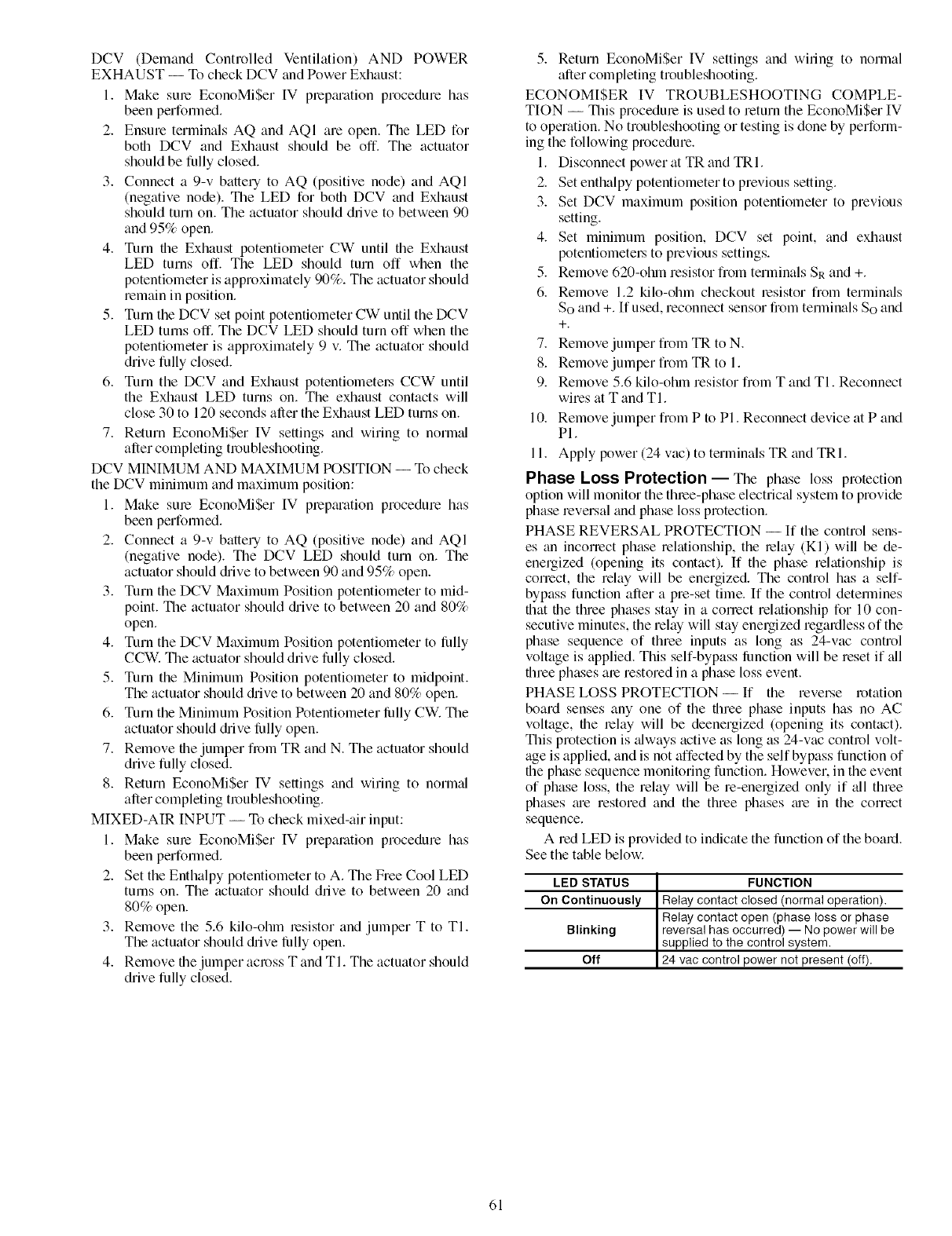
DCV (DemandControlledVentilation)AND POWER
EXHAUST-- TocheckDCVandPowerExhaust:
1. MakesumEconoMi$erIV prepguationprocedurehas
beenperformed.
2. EnsureterminalsAQandAQI areopen.TheLEDfor
bofllDCVandExhaustshouldbeoff. Theactuator
shouldbefullyclosed.
3. Connecta9-vbatteryto AQ(positivenode)andAQI
(negativenode).TheLEDforbothDCVandExhaust
shouldturnon.Theactuatorshoulddrivetobetween90
and95%open.
4. TurnfileExhaustpotentiometerCWuntiltheExhaust
LEDturnsoff.TheLEDshouldturnoff whenthe
potentiometerisapproximately90%.Theactuatorshould
remaininposition.
5. TurntheDCVsetpointpotentiometerCWuntiltheDCV
LEDturnsoff.TheDCVLEDshouldturnoffwhenthe
potentiometerisapproximately9v.Theactuatorshould
drivefullyclosed.
6. TurntheDCVandExhaustpotentiometel.sCCWuntil
theExhaustLEDturnson.Theexhaustcontactswill
close30to120secondsaftertheExhaustLEDturnson.
7. ReturnEconoMi$erIV settingsandwiringto norm_d
aftercompletingtroubleshooting.
DCVMINIMUMANDMAXIMUMPOSITION-- Tocheck
theDCVminimumandmaximumposition:
1. MakesumEconoMi$erIV prepmationprocedurehas
beenperformed.
2. Connect a 9-v battery to AQ (positive node) and AQI
(negative node). The DCV LED should turn on. The
actuator should drive to between 90 and 95% open.
3. Turn the DCV Maximum Position potentiometer to mid-
point. The actuator should &ive to between 20 and 80%
open.
4. Turn the DCV Maximum Position potentiometer to lhlly
CCW. The actuator should drive fully closed.
5. Turn the Minimum Position potentiometer to midpoint.
The actuator should drive to between 20 and 80% open.
6. Turn the Minimum Position Potentiometer lhlly CW. The
actuator should drive lhlly open.
7. Remove the jumper fi_m TR and N. The actuator should
drive fully closed.
8. Return EconoMi$er IV settings and wiring to norm_d
after completing troubleshooting.
MIXED-AIR INPUT -- To check mixed-air input:
1. Make sum EconoMi$er IV preparation procedure has
been performed.
2. Set the Enthalpy potentiometer to A. The Free Cool LED
turns on. The actuator should drive to between 20 and
80% open.
3. Remove the 5.6 kilo-ohm lesistor and jumper T to TI.
The actuator should drive lhlly open.
4. Remove the jumper across T and TI. The actuator should
drive fully closed.
5. Return EconoMi$er IV settings and wiring to normal
after completing troubleshooting.
ECONOM[$ER IV TROUBLESHOOTING COMPLE-
TION -- This procedure is used to return the EconoMiSer IV
to operation. No troubleshooting or testing is done by perform-
ing the following procedure.
1. Disconnect power at TR and TRI.
2. Set enthalpy potentiometer to previous setting.
3. Set DCV maximum position potentiometer to previous
setting.
4. Set minimum position, DCV set point, and exhaust
potentiometel.s to previous settings.
5. Remove 620-ohln resistor from terminals SR and +.
6. Remove 1.2 kilo-ohm checkout resistor from terminals
So and +. [fused, reconnect sensor from temrinals So and
+.
7. Remove jumper from TR to N.
8. Remove jumper from TR to 1.
9. Remove 5.6 kilo-ohm resistor from T and TI. Reconnect
wires at T and TI.
10. Remove jumper from P to PI. Reconnect device at P and
PI.
11. Apply power (24 vac) to terminals TR and TRI.
Phase Loss Protection- The phase loss protection
option will monitor the throe-phase electric;d system to provide
phase reversal and phase loss protection.
PHASE REVERSAL PROTECTION -- If the control sens-
es an incorrect phase relationship, the relay (KI) will be de-
energized (opening its contact). If the phase relationship is
correct, the relay will be energized. The control has a self-
bypass function after a pre-set time. If the control detemrines
flint file three phases stay in a correct relationship for 10 con-
secutive minutes, the relay will stay energized regardless of the
phase sequence of three inputs as long as 24-vac control
voltage is applied. This self-bypass lhnction will be reset if _dl
three phases are restored in a phase loss event.
PHASE LOSS PROTECTION-- If the reverse rotation
board senses any one of the three phase inputs has no AC
voltage, file relay will be deenergized (opening its contact).
This protection is _dways active as long as 24-vac control volt-
age is applied, and is not affected by the self bypass function of
the phase sequence monitoring function. However. in the event
of phase loss, the relay will be re-energized only if all three
phases m'e restored and the three phases me in the correct
sequence.
A red LED is provided to indicate the function of the board.
See the table below.
LED STATUS FUNCTION
On Continuously Relay contact closed (normal operation).
Relay contact open (phase loss or phase
Blinking reversal has occurred) -- No power will be
supplied to the control system.
Off 24 vac control power not present (off).
61

Copyright 2005 Carrier Corporation
Manufacturer reserves the right to discontinue, or change at any time, specifications or designs without notice and without incurring obligations.
PC 111 Catalog No. 534-80211 Printed in U.S.A. Form 48PG-10SI Pg 62 9-05 Replaces: New

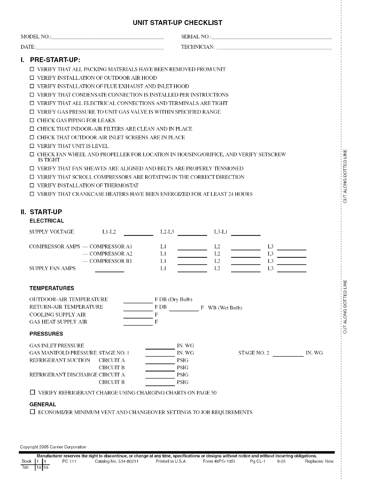
UNIT START-UP CHECKLIST
MODEL NO.: SERIAL NO.:
DATE: TECHNICIAN:
PRE-START-UP:
[] VERIFY THAT ALL PACKING MATERIALS HAVE BEEN REMOVED FROM UNIT
[] VERIFY INSTALLATION OF OUTDOOR AIR HOOD
[] VERIFY INSTALLATION OF FLUE EXHAUST AND INLET HOOD
[] VERIFY THAT CONDENSATE CONNECTION IS INSTALLED PER INSTRUCTIONS
[] VERIFY THAT ALL ELECTRICAL CONNECTIONS AND TERMINALS ARE TIGHT
[] VERIFY GAS PRESSURE TO UNIT GAS VALVE IS WITHIN SPECIFIED RANGE
[] CHECK GAS PIPING FOR LEAKS
[] CHECK THAT INDOOR-AIR FILTERS ARE CLEAN AND IN PLACE
[] CHECK THAT OUTDOOR AIR INLET SCREENS ARE IN PLACE
[] VERIFY THAT UNIT IS LEVEL
[] CHECK FAN WHEEL AND PROPELLER FOR LOCATION IN HOUSING/ORIFICE, AND VERIFY SETSCREW
IS TIGHT
[] VERIFY THAT FAN SHEAVES ARE ALIGNED AND BELTS ARE PROPERLY TENSIONED
[] VERIFY THAT SCROLL COMPRESSORS ARE ROTATING IN THE CORRECT DIRECTION
[] VERIFY INSTALLATION OF THERMOSTAT
[] VERIFY THAT CRANKCASE HEATERS HAVE BEEN ENERGIZED FOR AT LEAST 24 HOURS
II. START-UP
ELECTRICAL
SUPPLY VOLTAGE LI-L2 L2-L3 L3-LI
COMPRESSOR AMPS -- COMPRESSOR AI
COMPRESSOR A2
COMPRESSOR B 1
SUPPLY FAN AMPS
LI L2 L3
LI L2 L3
LI L2 L3
LI L2 L3
TEMPERATURES
OUTDOOR-AIR TEMPERATURE
RETURN-AIR TEMPERATURE
COOLING SUPPLY AIR
GAS HEAT SUPPLY AIR
F DB (Dry Bulb)
F DB
F
F
F WB (Wet Bulb)
PRESSURES
GAS INLET PRESSURE
GAS MANIFOLf) PRESSURE STAGE NO. 1
REFRIGERANT SUCTION CIRCUIT A
CIRCUIT B
REFRIGERANT DISCHARGE CIRCUIT A
CIRCUIT B
IN. WG
IN. WG
PSIG
PSIG
PSIG
PSIG
[] VERIFY REFRIGERANT CHARGE USING CHARGING CHARTS ON PAGE 50
STAGE NO. 2
GENERAL
[] ECONOMIZERMINIMUMVENTANDCHANGEOVERSETTINGSTOJOB REQUIREMENTS
IN. WG
Copyright 2005 Carrier Corporation
Manufacturer reserves the right to discontinue, or change at any time, specifications or designs without notice and without incurring obligations.
Book 1 14 PC 111 Catalog No, 534-80211 Printed in U.S.A. Form 48PG-10SI Pg CL-1 9-05 Replaces: New
Tab 1a 16a
LU
z
LU
z
o
<
o
LU
z
LU
Z
o
<
o
