CARRIER Controls And HVAC Accessories Manual L0523312
User Manual: CARRIER CARRIER Controls and HVAC Accessories Manual CARRIER Controls and HVAC Accessories Owner's Manual, CARRIER Controls and HVAC Accessories installation guides
Open the PDF directly: View PDF ![]() .
.
Page Count: 2
installation instructions
Replacement Direct-Drive
Damper Actuator
DAMPACT45DEG-R
DAMPACT90DEG-R
NOTE: Read the entire h]struction manual beJ_>restarting the installation.
This symbol --> indicates a change sil/ce the hst issue.
SAFETY CONSiDERATiONS
Installing aud '_er%cing air conditioning equipment can be hazardous due io system pressures, electrical componenIs, aud lttel gases. Only trained
and qua_ilied perso]mel should install, service, or repair air conditioniug equipmer_I.
LlnIraiuedpersolme_ can perlbrm basic mainIel_ance luuctions such as cleaning coils, or cleaning and lep_acing fi_ers. All other operations should
be per%rmed by {rained service personnel. When workir]g orl heating & air conditioning equipment, observe precautions in the literature, <m tags,
and on labels attached m the unit.
Recoguize salcty inlorl't]ation, This is the safcty-alert symbol z_ • When you see this symbol on the unit and ill irlstructior]s or malmals, be alert
to the potential lor personal ilt}ury.
Undersiand the siglm_ words DANGER, WARNING, and CALITK)N. These words are used with the safety-alert symbol. DANGER identifies the
most serious hazards which wiH result in severe personal injury or death. WARNING sigaifies a hazard which eoMd result in personal ilt}ury or
deaih. CALITK)N is used to identify unsaid: practices which may result ill mil-_orpersollai irLjuryor product and property damage. NOTE is used
to higMight suggestkms which willl result in enhanced installation, reliabi]iIy, or operation.
Follow all salary codes. Wear salary g_asses and work gloves. Have a fire extinguisher availaNe if needed. React ihese iustructions thoroughly alld
lotlow all warnings or cauIions attached m the unit, Consult k_cal building codes and Nationa! Electrical Code (NEC) for specia! requirements.
Belore proceeding wiIh installation, il/spect thoroughly lbr shippiug damage. Notily shipper immediately if any damage is lbund. Check lbr proper
clearances ol moving paris.
The qualified il-_siaHeror agency must use lactory-auihorized kits or accessories when modifying this product. Refer to the individua! insmlctkms
packaged with the kits or accessories wherl installing
z_x WARNING: ELECTRICAL SHOCK HAZARD
Failure to follow this warning could resuR in personal injury or death. Before performing instaIBation, service or maintenance
operations on this system turn off aml main power switches and/or disconnects. There may be more than one switch or
disconnect, Turn off accessory power switch(s) if applicable. TAG DISCONNECT SWITCH(S) WITH A SUITABLE WARNING
LABEL,
--> iNTRODUCTiON
Kit Part No. DAMPA(_T45DE(_-R and DAMPA(_TgODEG-R are the replacemeut actuators desigued ]i_r resideraia] dampers. These kits couIain
the aciuator, au auti-rotaIkm mouuIing screw, al-_dan Installation hlstruction. They caT1be used on dampers having rouud shales or the newer dua_
llalted shalts. The 24-vac direct-drive actuaor provides smooth, qlliet per%rmgmce in a smalter package. The DAMPACT45DEG-R kit is inIended
lot round and newer rectangular dampers having a 45 degree rotation lrom closed to open. The DAMPACT90DEG-R kit is for slip-in and okler
reclangu_ar dampers which rotate through 90 degrees h'om closed to open. Ninety degree rectangular dampers have round shalis while 45 degree
rectangular dampers have dua] flatted shafts with an arrow on tl_e shali end.
Z_ CAUTION: UNiT OPERATIONAL HAZARD
Failure to follow this caution may result in improper unit operation. An operational problem will occur if the wrong travel
actuator is applied to the wrong damper. Use DAMPACT45DEG-R for 45 degree dampers and DAMPAOTg0DEG-R for 90
degree dampers.
ACTUATOR FEATURES
1. A l/2-in, direct-drive mouuting hub lor securing damper blade and shall to :lcttmtor housil/g.
2. Spriug-loaded disengagemeuI (quick blade re_ease burma) lk_rmomentary release of main gear arid damper blade.
---> 3. Recessed termiua_ block wiring.
INSTALLATION
Repb_cing tl_edamper actmttor can be perR_rmed on dampers ah'eady installed ill ihe duct system. Dampers shoaM _t_'_' _t_rS be iustalled v, here the
actuator is visible lbr inspection and accessible lbr serviciug. A black marker line or a molded arrow on the end ol the damper shali can be used
to indicate the damper blade position.
Catalog No,: IM-DAMP-18 Cancels: IM-DAMP-13 Printed in U,S,A, 8-05
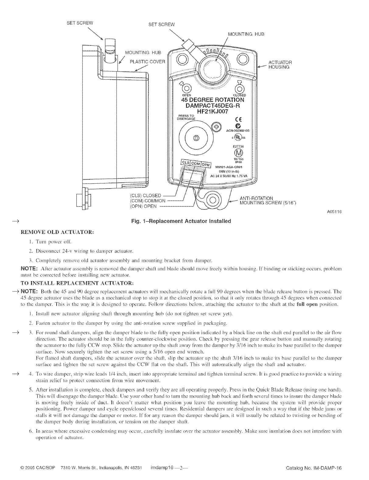
SET SCREW
E
SETSCREW
MOUNTING HUB
PLASTIC COVER
(OPN) OPEN J
MOUNTING HUB
ACTUATOR
HOUSING
OPEN OLOSED
45 DEGREE ROTATION
DAMPACT45DEG-R
HF21KJ007
PNKSS TO
DISENGAGE _ {
AG N:00291_810g
C@US
E27734
@
18/IGS
IP40
"E-;11:12'
,// ,o2,wor00
-ROTATION
_k_._,t "_- MOUNTING SCREW (5/16")
--> Fig. 1=Replacement Actuator Installed
REMOVE OLD ACTUATOR:
I. Turn power oil
2. Discom_ect 24-v wiring to damper actuator.
3. Completely remove oM aciuator assembly and irloul_tir_g bracket i}om damper.
A05116
NOTE: Alter actuator assembly is removed the damper shaft and blade shoukl move freely withil_ housil_g. [1 bindil_g or stickil_g occurs, problem
must be corrected befbm il_staHil_g new actuator.
TO INSTALL REPLACEMENT ACTUATOR:
---> NOTE: Both the 45 al_d 90 degree replacemem actuators will mecharfically rotate a ful! 90 degrees whel-_ the blade release button is pressed. The
45 degree actuator uses the blade as a mechal-dcal stop to stop it at the closed positi<m, so that it only rotates through 45 degrees when cormected
to the damper. This is the way it is desig!_ed to operate. Follow directions below, attaching tl_e actuator to the shaft at the fu]ll open position.
I. h_stall new actuator aligl_ing shali through mouluing hub (do not tighten set screw yet).
2. Fasten actuator to the damper by using the mai-rotation screw supplied it* packaging.
---> 3. For round shaft dampers, aligl-_ the damper Nade to the li_![y opel_ position ir_dicated by a Nack Hl_e on the shall end paral]e[ io the air flow
direciion. The actuator sholfld be in ihe lully cormier-clockwise position. Check by pressing the gear release breton al_d manHally rotating
the actuator to the [_/lly CCW stop. Slide the actuator up the shaJ) away from the damper by 3/16 inch to make its base paraHe_ to the damper
sin:lace. Now securely tighten the set screw using a 5/!6 open el-_d wrench.
For flaited shaft dampers, slide ibe actuator over the shall slip the actuator up the shah 3/16 inch to make its base parallel to the damper
surlace arid tighien the set screw agail_st the CCW liar on the shaft. This will automatically aligl_ the shaft and actuator.
--€ 4. To wire damper, strip wire _eads 1/4 inch, il-_sert inlo appropriate terminal al_d tighten terminal screw. It is good practice to provide a wiring
strain re]iel to protect co[lllection JroH1 wire irloveli]e[lt,
5. After insta_iatkm is cnlrlp_ete, check dampers and verify they are all operatil_g properly. Press in the Quick Blade Release (usil_g one halx!).
This will disengage the damper blade. Use your other hand to turn II_e monluil-_g hub back and %rth several times to insure the damper blade
is moving freely inside ol duct. ]li doeslFt matier what position you leave the monntil_g hub, because the system will provide proper
positiol-_il-_g. Power damper and cycle operdclosed several times. Resideluial dampers are desig!_ed il-tsHcha way tl_at if the blade jams or
stalls it wil_ m_t damage ihe damper or motor. Ill lbr any reason the damper should .}alrl, it will usually be related to twistil_g or bending of
the damper body durh_g instalhtiom or tension or* the damper shaft.
6. ll_ areas where excessive condensil_g may occur, careltflly insulate over the aciuator assembly. Make sure ir_sulatiol_ does not ilaerli:re with
operatior_ of actuator.
© 2005 CAC/BDP 7310 W. Morris St,, Indianapolis, IN 46231 imdamp16 2-- Catalog No. IM-DAMP-16
