CARRIER Controls And HVAC Accessories Manual L0604623
User Manual: CARRIER CARRIER Controls and HVAC Accessories Manual CARRIER Controls and HVAC Accessories Owner's Manual, CARRIER Controls and HVAC Accessories installation guides
Open the PDF directly: View PDF ![]() .
.
Page Count: 10
Installation Instructions
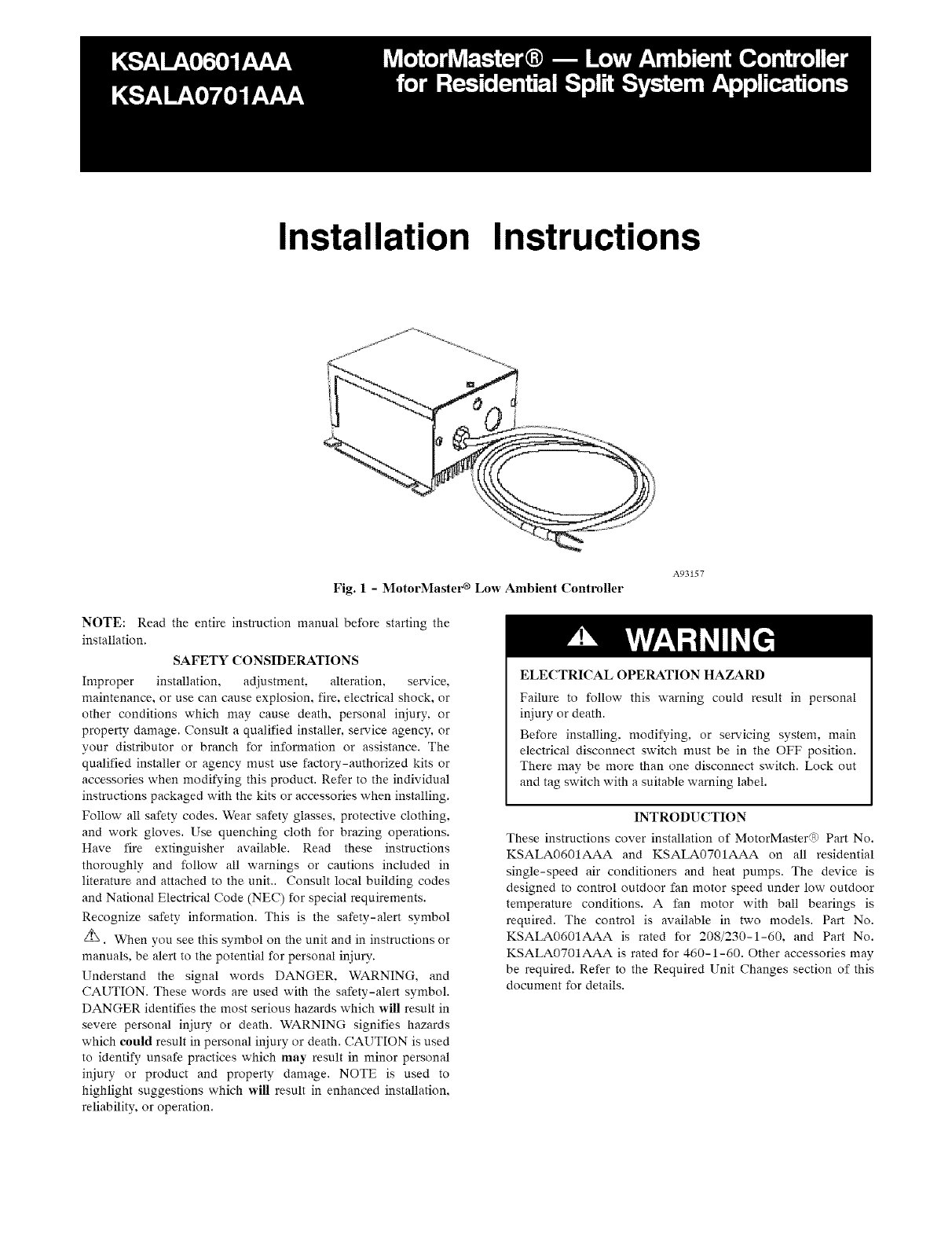
Fig. 1-MotorMastel _ Low Ambient Controller
A93157
NOTE: Read the entire instruction manual before starting the
installation.
SAFETY CONSIDERATIONS
Improper installation, adjustment, alteration, service,
maintenance, or use can cause explosion, fire, electrical shock, or
other conditions which may cause death, personal injury, or
property damage. Consult a qualified installer, service agency, or
your distributor or branch for information or assistance. The
qualified installer or agency must use factory-authorized kits or
accessories when modifying this product. Refer to the individual
instructions packaged with the kits or accessories when installing.
Follow all safety codes. Wear safety glasses, protective clothing,
and work gloves. Use quenching cloth for brazing operations.
Have fire extinguisher available. Read these instructions
thoroughly and follow all warnings or cautions included in
literature and attached to the unit.. Consult local building codes
and National Electrical Code (NEC) for special requirements.
Recognize safety information. This is the safety-alert symbol
z_. When you see this symbol on the unit and in instructions or
manuals, be alert to the potential for personal injury.
Understand the signal words DANGER. WARNING, and
CAUTION. These words are used with the safety-alert symbol.
DANGER identifies the most serious hazards which will result in
severe personal injury or death. WARNING signifies hazards
which could result in personal injury or death. CAUTION is used
to identify unsafe practices which may result in minor personal
injury or product and property damage. NOTE is used to
highlight suggestions which will result in enhanced installation,
reliability, or operation.
ELECTRICAL OPERATION HAZARD
Failure to follow this warning could result in personal
injury or death.
Before installing, modifying, or servicing system, main
electrical disconnect switch must be in the OFF position.
There may be more than one disconnect switch. Lock out
and tag switch with a suitable warning label.
INTRODUCTION
These instructions cover installation of MotorMaster@ Part No.
KSALA0601AAA and KSALA0701AAA on all residential
single-speed air conditioners and heat pumps. The device is
designed to control outdoor fan motor speed under low outdoor
temperature conditions. A fan motor with ball bearings is
required. The control is available in two models. Part No.
KSALA0601AAA is rated for 208/230-1-60. and Part No.
KSALA0701AAA is rated for 460-1-60. Other accessories may
be required. Refer to the Required Unit Changes section of this
document for details.
DESCRIPTIONANDUSAGE
TheMotorMaster_isafanspeedcontroldeviceactivatedbya
temperaturesensor.It is specificallydesignedto control
condenserfanmotorspeedin responseto thesaturated
condensingtemperatureduringoperationincoolingmodeonly.
For outdoortemperaturesdownto -20_'F.it maintains
condensingtemperatureat100"F-+10°F.(SeeFig.1.)
Themountingcontrolconsistsofasolid-statecircuitonaprinted
circuitboardinanaluminumextrusion,andasensorassemblyto
bemountedtoareturnbendontheunit'scondensercoil.Awire
fromthesensorisconnectedtothecircuitboardinthecontrol
box.
Partsnecessaryformountingcontrolandsensorassemblyare
includedin the kit. Eitherassemblycanbe replaced
independentlyoftheother.If anydamagetotheprintedcircuit
boardor componentsis observedwhenunpackingcontrol
assembly,returnforreplacement.
TheMotorMaster®maintainspropercondensingtemperatureat
anyambienttemperaturedownto-20_'F.Nofieldadjustmentsor
calibrationsarerequired.
Thefollowingmustbeobserved:
• Ifspecialfanmotorsorotheraccessoriesarerequired,
installwherenecessary.
• Measureunitpowersupplyvoltage.Itmustmeet
minimumvoltagespecifiedonunitratingplateand
matchvoltageratingofMotorMaster®.
• Makesureallunitsaremodifiedforwinterstartcontrol
whenneeded.
• Checkthatcontrollocationisasspecified.
• Checkthatsensorlocationisasspecified.
• Makesurethatsensorwiringroutingisasspecified.
• Makesurewindbafflesareinstalledonlyif required.
• Forheatpumpunits,makesureisolationrelayis
available.
INSTALLATION
UNITDAMAGEHAZARD
Failuretofollowthiscautionmayresultinunitdamage.
Exerciseextremecautionwhendrillingholes.Donot
puncturecoiland/ortubing.
PROCEDURE 1 -- MOUNTING CONTROL ASSEMBLY
1. Make sure all power to unit is turned off
ELECTRICAL OPERATION HAZARD
Failure to follow this warning could result in personal
injury or death.
Before installing or servicing system, always turn off main
power to system. There may be more than one disconnect
switch.
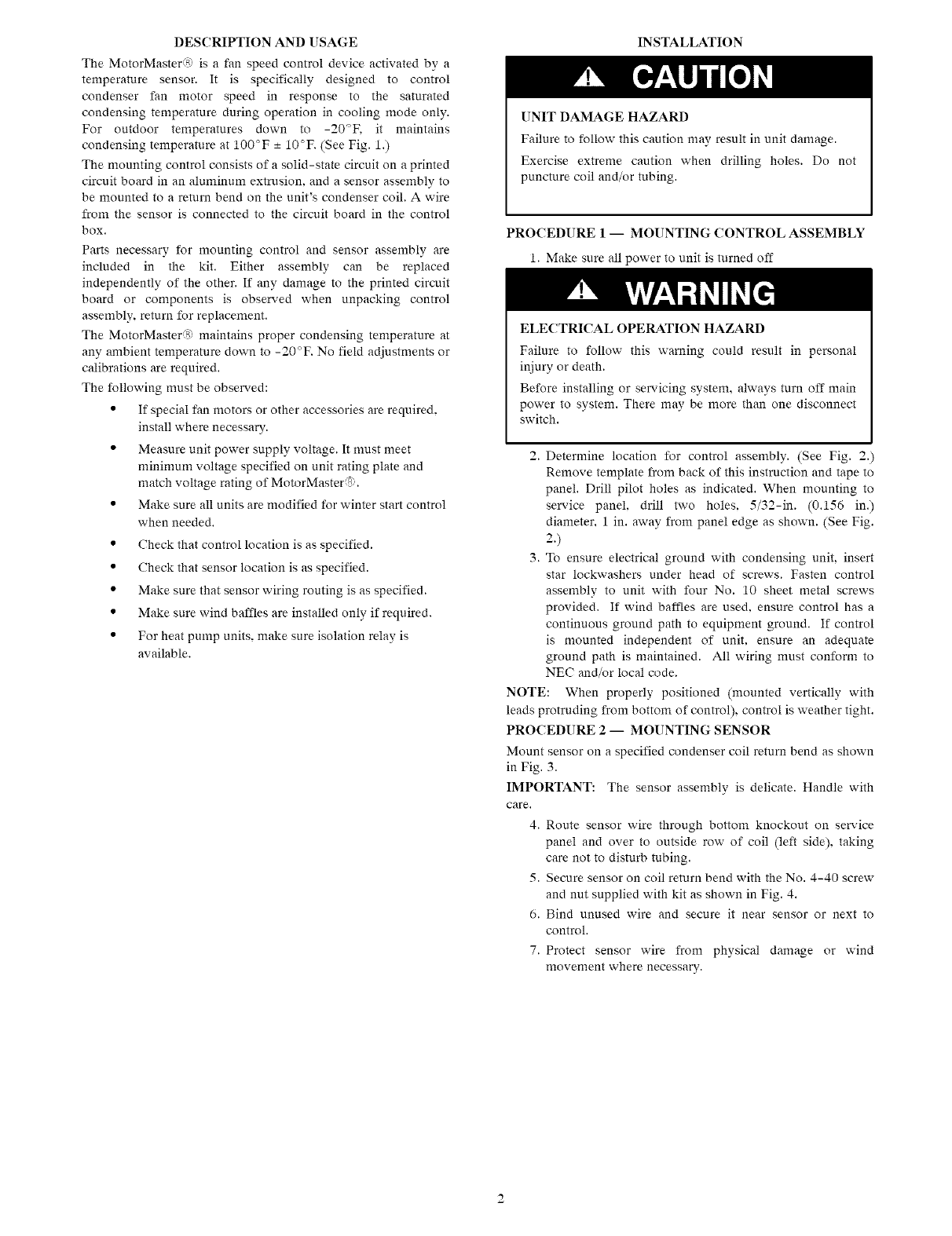
2. Determine location for control assembly. (See Fig. 2.
Remove template from back of this instruction and tape to
panel. Drill pilot holes as indicated. When mounting to
service panel, drill two holes. 5/32-in. (0.156 in.)
diameter. 1 in. away from panel edge as shown. (See Fig.
2.)
3. To ensure electrical ground with condensing unit. insert
star lockwashers under head of screws. Fasten control
assembly to unit with four No. 10 sheet metal screws
provided. If wind baffles are used. ensure control has a
continuous ground path to equipment ground. If control
is mounted independent of unit. ensure an adequate
ground path is maintained. All wiring must conform to
NEC and/or local code.
NOTE: When properly positioned (mounted vertically with
leads protruding from bottom of control), control is weather tight.
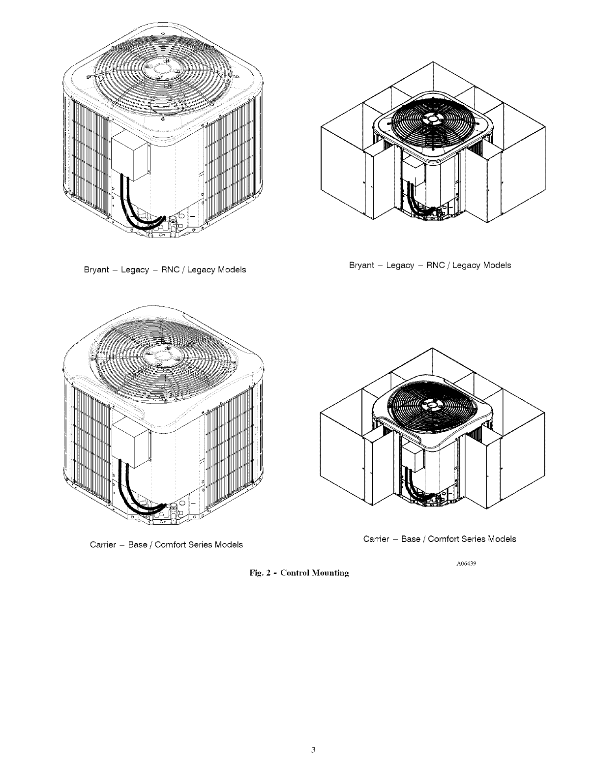
PROCEDURE 2 -- MOUNTING SENSOR
Mount sensor on a specified condenser coil return bend as shown
in Fig. 3.
IMPORTANT: The sensor assembly is delicate. Handle with
care.
4. Route sensor wire through bottom knockout on service
panel and over to outside row of coil (left side), taking
care not to disturb tubing.
5. Secure sensor on coil return bend with the No. 4-40 screw
and nut supplied with kit as shown in Fig. 4.
6. Bind unused wire and secure it near sensor or next to
control.
7. Protect sensor wire from physical damage or wind
movement where necessary.
Bryant - Legacy - RNC /Legacy Models Bryant - Legacy - RNC /Legacy Models
Carrier - Base /Comfort Series Models
Fig. 2-Control Mounting
Carrier - Base /Comfort Series Models
A06439
TOP OF COIL
j---- 0
,4
-VAPORIN
"_SENSOR LOCATION
LIQUID OUT OR
JUMPER TUBE
TOP OF COIL
0
_SENSOR LOCATION
VAPOR IN
-,,911_--
LIQUID OUT
TOP OF COIL
o o
_°
TOP OF COIL
LIQUID__...._OUT
SENSORLOCATION
VAPOR IN
_SENSOR LOCATION
VAPOR IN
--.,,91--
LIQUID OUT
--I1,,,--
TOP OF COIL
LIQ_UIDOUT TOP OF COIL
i i "--SENSORLOCATION
_VAP°R 2
TOP OF COIL
-C_ VAPOR IN
0 ..t.
0
_ SENSOR LOCATION
O
LIQUID OUT
VAPOR IN
SENSOR LOCATION
--lID--
LIQUID OUT
OR
JUMPERTUBE
Fig. 3- Sensor Location on Return End of Coil
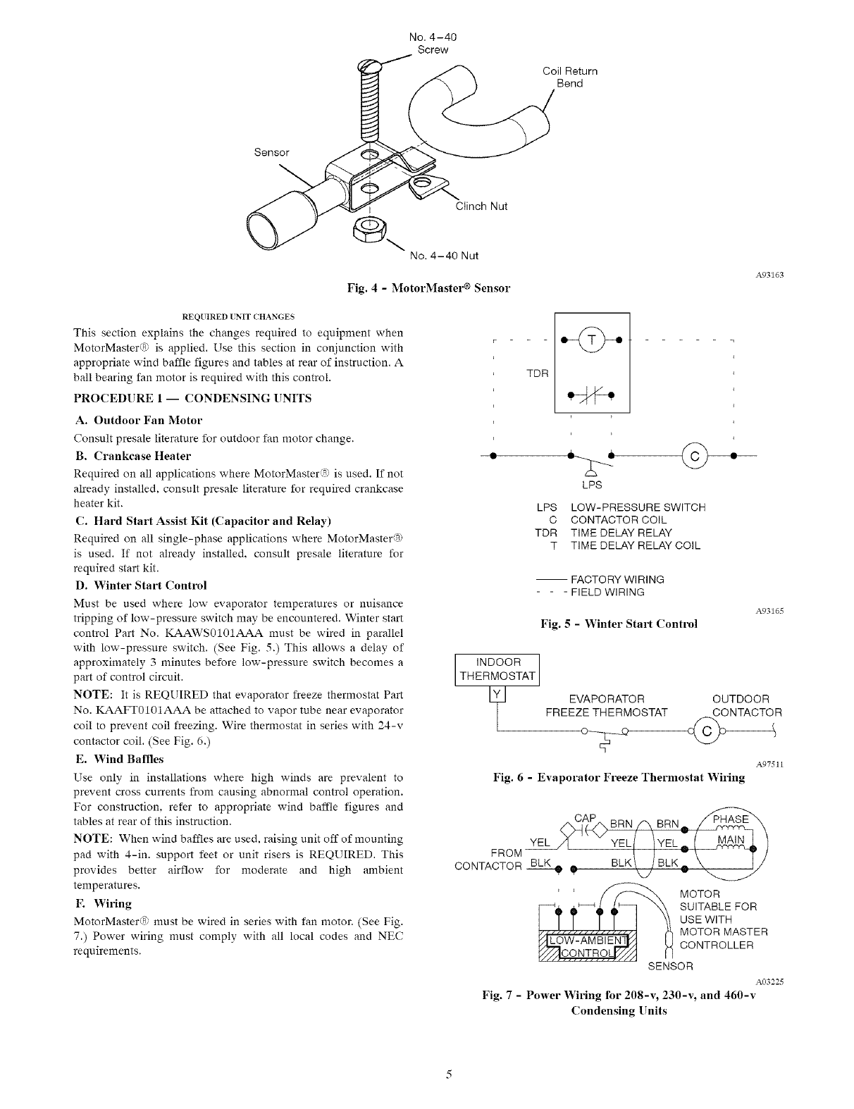
No. 4-40
Screw
Coil Return
Bend
Sensor
I Ctinch Nut
@\ No. 4-40 Nut
Fig. 4 - MotorMaster ® Sensor
A93163
REQUIRED [NIT CHANGES
This section explains the changes required to equipment when
MeterMaster( a_,is applied. Use this section in conjunction with
appropriate wind baffle figures and tables at rear of instruction. A
ball bearing fan motor is required with this control.
PROCEDURE 1-- CONDENSING UNITS
A. Outdoor Fan Motor
Consult presale literature for outdoor fan motor change.
B. Crankcase Heater
Required on all applications where MoterMaster s_ is used. If not
already installed, consult presale literature for required crankcase
heater kit.
C. Hard Start Assist Kit (Capacitor and Relay)
Required on all single-phase applications where MoterMaster%
is used. If net already installed, consult presale literature fer
required start kit.
D. Winter Start Control
Must be used where low evaporator temperatures or nuisance
tripping of low-pressure switch may be encountered. Winter start
control Part No. KAAWS0101AAA must be wired in parallel
with low-pressure switch. (See Fig. 5.) This allows a delay of
approximately 3 minutes before low-pressure switch becomes a
part of control circuit.
NOTE: It is REQUIRED that evaporator freeze thermostat Part
No. KAAFT0101AAA be attached to vapor tube near evaporator
coil to prevent coil freezing. Wire thermostat in series with 24-v
contactor coil. (See Fig. 6.)
E. Wind Baffles
Use only in installations where high winds are prevalent to
prevent cross currents from causing abnormal control operation.
For construction, refer to appropriate wind baffle figures and
tables at rear of this instruction.
NOTE: When wind baffles are used. raising unit off of mounting
pad with 4-in. support feet or unit risers is REQUIRED. This
provides better airflow for moderate and high ambient
temperatures.
F. WMng
MotorMasterdS'_ must be wired in series with fan motor. (See Fig.
7.) Power wiring must comply with all local codes and NEC
requirements.
TDR
---2---
LPS
LPS LOW-PRESSURE SWITCH
C CONTACTOR COIL
TDR TIME DELAY RELAY
T TIME DELAY RELAY COIL
-- FACTORY WIRING
- - - FIELD WIRING
Fig. 5- Winter Start Control
A93165
INDOOR
THERMOSTAT
EVAPORATOR OUTDOOR
FREEZE THERMOSTAT CONTACTO R
Fig. 6 - Evaporator Freeze Thermostat Wiring
A97511
FROM--
CONTACTOR_ _BLK\ /BLK_.. _[/
MOTOR
SUITABLE FOR
USE WITH
MOTOR MASTER
CONTROLLER
SENSOR
A03225
Fig. 7 - Power Wiring for 208-v, 230-v, and 460-v
Condensing Units
PRO('EDURE2-- HEATPUMPS
A. Outdoor Fan Motor
Consult presale literature for outdoor fan motor change.
B. ('rankcase Heater
Required on all applications where MotorMaster'7_; is used. If not
already installed, consult presale literature for required crankcase
heater.
('. Hard Start Assist Kit (Capacitor and Relay)
Required on all single-phase applications where MotorMaster_:_;
is used. If not already installed, consult presale literature for
required accessory start kit.
NOTE: It is REQUIRED that evaporator freeze thermostat Part
No. KAAFT0101AAA be applied to the evaporator coil to
prevent coil freezing.
Wire thermostat in series with 24-v contactor coil. (See Fig. 6.)
D. Wind Baffles
Use only in installations where high winds are prevalent to
prevent cross currents from causing abnormal control operation.
For construction, refer to appropriate wind baffle figures and
tables at rear of instruction
NOTE: When wind baffles are used, raising unit off of mounting
pad with 4-in. support feet or unit risers is REQUIRED. This
provides better airflow for moderate and high ambient
temperatures.
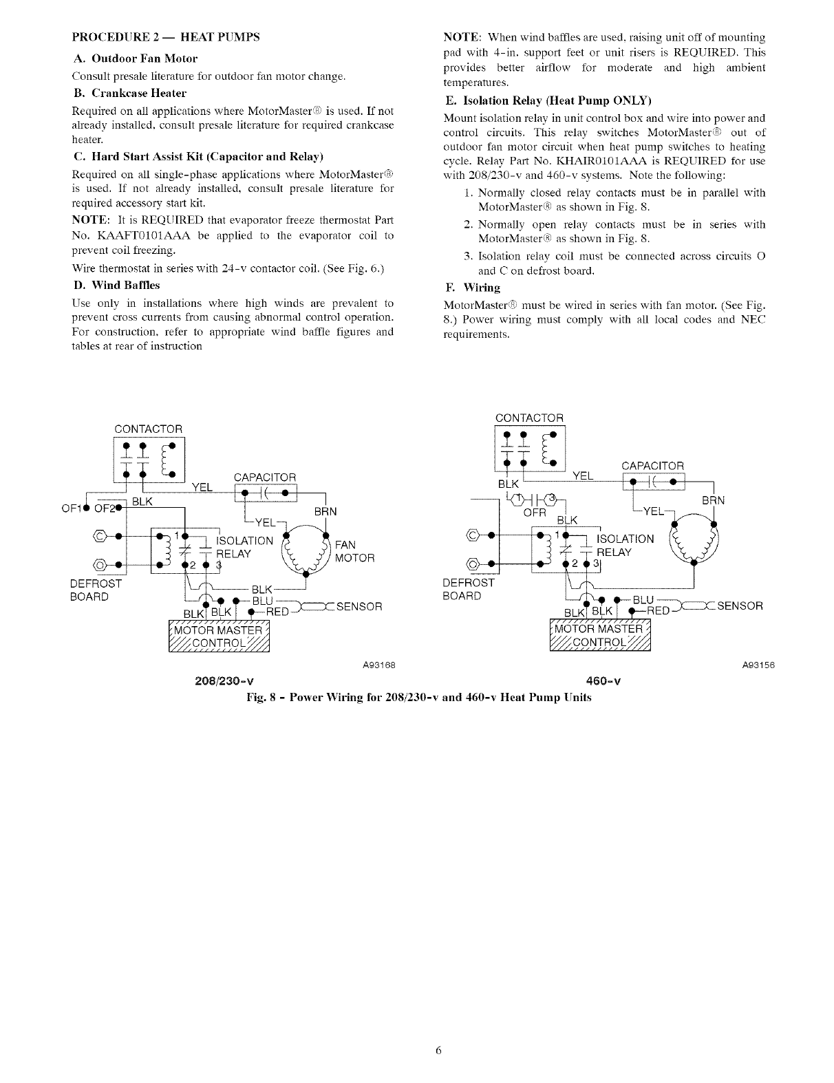
E. Isolation Relay (Heat Pump ONLY)
Mount isolation relay in unit control box and wire into power and
control circuits. This relay switches MotorMaster® out of
outdoor fan motor circuit when heat pump switches to heating
cycle. Relay Part No. KHAIR0101AAA is REQUIRED for use
with 208/230-v and 460-v systems. Note the following:
1. Normally closed relay contacts must be in parallel with
MotorMaster® as shown in Fig. 8.
2. Normally open relay contacts must be in series with
MotorMaster® as shown in Fig. 8.
3. Isolation relay coil must be connected across circuits O
and C on defrost board.
F. Wiring
MotorMaster_ must be wired in series with fan motor. (See Fig.
8.) Power wiring must comply with all local codes and NEC
requirements.
CONTACTOR
OF4
_._, oS,_L_ _SEN SO R
A93168
208/230-v
CONTACTOR
- L_OFR_BL K LYEL _ Bt_IN
DEF _!N__ .F_c.S_._LT'_R_SENSOR
A93156
460-v
Fig. 8 - Power Wiring for 208/230-v and 460-v Heat Pump Units
START-UP
TostartupunitsequippedwithaccessoryMotorMaster®:
1.Turnunitpoweron.
2.Setthermostatbelowroomtemperature.
3.Waitatleast5minutesif unitisequippedwithadelay
circuit.Fanmotorstarts15secbeforecompressorwhen
standarddelaycircuitsareusedandmay:
a.Notoperatewhenambientisbelow50°F.
b.Runatslowspeedwhenambientisbetween70°Fand
80°F.
c.Run at or near full speed when ambient is above 80°F.
4. When compressor starts, fan speed modulates smoothly to
proper controlled speed based on saturated condensing
temperature. After system has run and settled out,
saturation temperature is approximately 100°F -+ 10°K if
the outdoor ambient is below 60°F.
10,000
9000
8000
Or) 7000
"1-
O
Z6000
W
0
Z
Or) 5000
t./)
I.,1..I
4000
3000
2000
lOOO
SERVICE
No field repairs are to be made on this kit. If either the sensor or
the control fails, it should be replaced.
If fan motor does not turn, check control as follows:
1. Check power to condensing unit.
2. Check for voltage across fan motor relay contacts.
3. Check for loose sensor wire connections in MotorMaster®
splice compartment.
4. Bypass MotorMaster® by connecting black wire from
unit contactor directly to black fan motor lead. (See Fig. 7
or 8 and unit wiring label.)
a. If fan does not turn, make sure motor is wired into
circuit properly and run capacitor is not defective.
Replace motor or capacitor if defective.
b. If fan motor runs, make sure that motor was wired in
series with MotorMaster®.
5. If motor runs when connected to single-phase voltage
supply, but does not run when connected in series with
MotorMaster®, check sensor as follows:
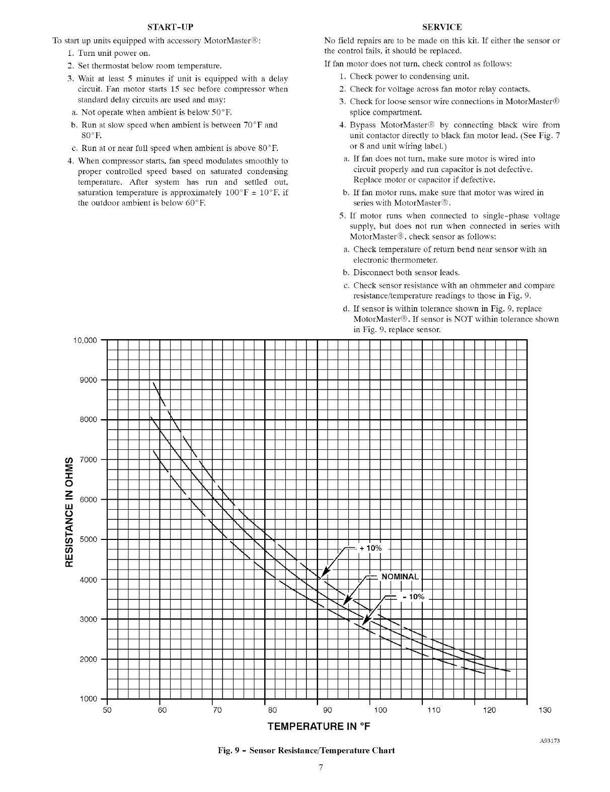
a. Check temperature of return bend near sensor with an
electronic thermometer.
b. Disconnect both sensor leads.
c. Check sensor resistance with an ohmmeter and compare
resistance/temperature readings to those in Fig. 9.
d. If sensor is within tolerance shown in Fig. 9, replace
MotorMaster®. If sensor is NOT within tolerance shown
in Fig. 9, replace sensor.
\\
'\ '\
\, \
\ \ \
k \'
\ ,,,\,, \1
\\, N
\1 ,\
\
\- \
\ \
\
\
\
\\
\
%
\
%
\
+ lO%
NOMINAL
- lO%
~ •
50 60 70 80 90 100
TEMPERATURE IN °F
Fig. 9 - Sensor Resistance/Temperature Chart
11o 120 130
A93173

15/16"
8" C-1
AT'L :SU%P%RAT STEEL
--'4 2-s,8"
6 REO'D TYP
1_2" TYP
1-9/16"
TYP
6" TYP
51/4" HOLE
14 REQ'D
- 9/16"
TYP
/4" TYP
D
4 REQ'D
OUTDOOR
UNIT
44 REQ'D
_! 16=1/2" TYP
BAFFLE
MAT'L: 20 GA STEEL
1/4" X 7/16" SLOT_
6 REO'D _._
t
AA
-BAFFLE
3 RE©'D
4---9/16" TYP
7
_" TYP
BAFFLE ASSEMBLY
Fig. 10 -Base /Mid-Tier Baffle Assembly
Table 2--Wind Baffle Dimensions for Entry and Mid-Tier Units (in.)
UNIT SIZE AA C11 C-2 C13 D
Small
Medium
25-3/4
31-1/4
35
Large
UNIT HEIGHT
25
28- 7/16
31-13/16
35-1/4
38- 5/8
42
45- 7/16
25-1/2
28-15/16
32-5/16
35 - 3/4
39-1/8
42-1/2
45-15/16
25-1/2
28-15/16
32-5/16
35 - 3/4
39-1/8
42-1/2
45-15/16
A
20-3/8
23-13/16
27-3/16
30- 5/8
34
37-3/8
40-13/16
20-3/8
23-13/16
27-3/16
30- 5/8
34
37-3/8
40-13/16
20-3/8
23-13/16
27-3/16
30- 5/8
34
37-3/8
40-13/16
B
10-I/16
11-3/4
13-1/2
15-3/16
16- 7/8
18-9/16
20-1/4
10-I/16
11-3/4
13-1/2
15-3/16
16- 7/8
18-9/16
20-1/4
10-I/16
11-3/4
13-1/2
15-3/16
16- 7/8
18-9/16
20-1/4
3-15/16
9- 3/8
13-3/16
1O- 7/8
16-5/16
20-1/8
6-1/8
11-9/16
15-3/8
A06450
41-7/8
47- 3/8
51-1/8


Copyright 2006 CAC' BDP • 73t0 W Mo::is St • Indianapolis, IN 46_31 P:_:_ted in USA
Ma mlfae_ul'er rese_'es the tlght to change, at any time. speeiliea tions and designs without notice and wit hou_ obligations.
10
Edition Date: 04_06 Catalo_ No: AG-KSAL&-01
Replaces: AG SALA 06
