CARRIER Package Units(both Units Combined) Manual L0606340
User Manual: CARRIER CARRIER Package Units(both units combined) Manual CARRIER Package Units(both units combined) Owner's Manual, CARRIER Package Units(both units combined) installation guides
Open the PDF directly: View PDF ![]() .
.
Page Count: 54
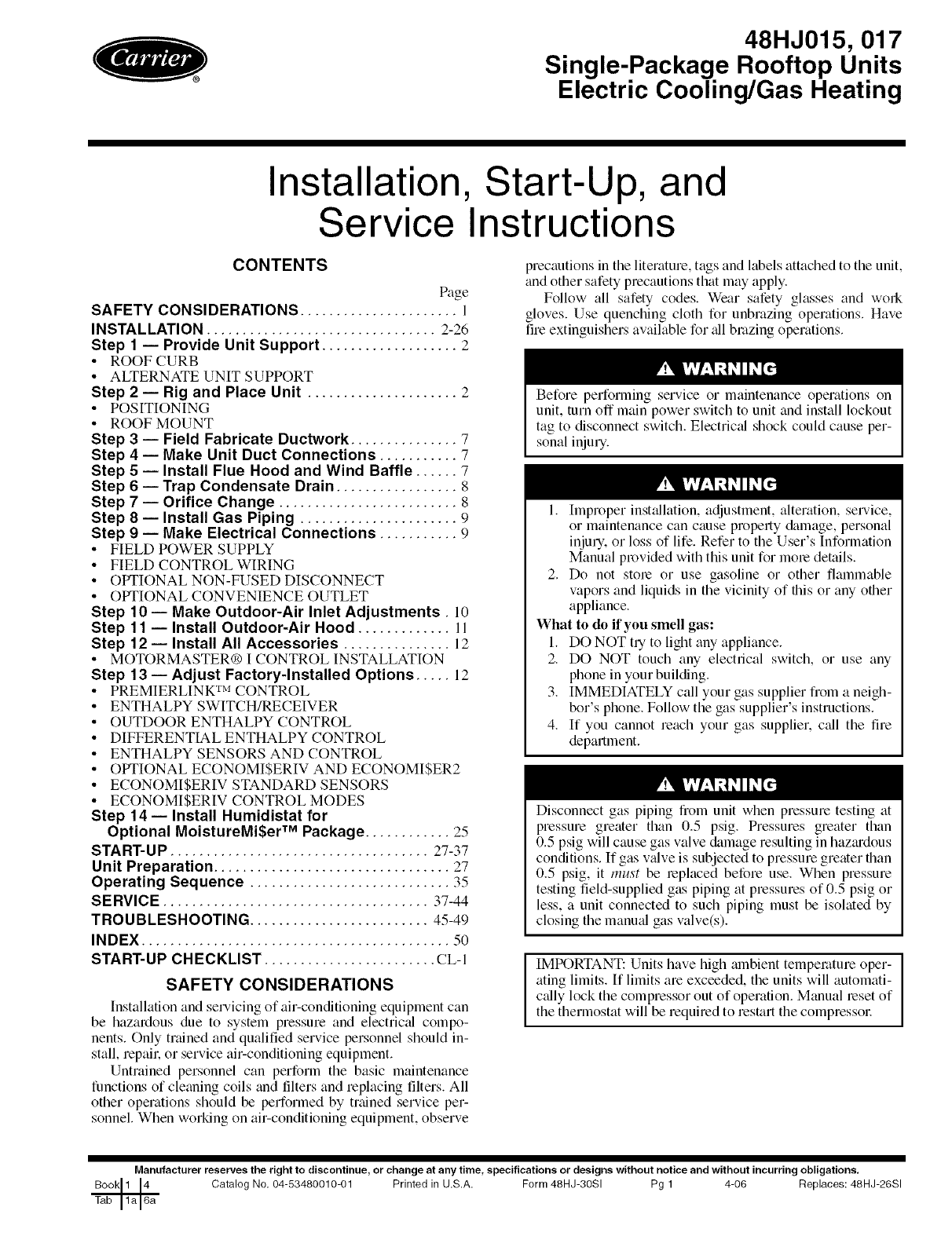
48HJ015, 017
Single-Package Rooftop Units
Electric Cooling/Gas Heating
Installation, Start-Up, and
Service Instructions
CONTENTS
Page
SAFETY CONSIDERATIONS ...................... 1
INSTALLATION ................................ 2-26
Step 1 -- Provide Unit Support ................... 2
• ROOF CURB
• ALTERNATE UNIT SUPPORT
Step 2 -- Rig and Place Unit ..................... 2
• POSITIONING
• ROOF MOUNT
Step 3-- Field Fabricate Ductwork ............... 7
Step 4 -- Make Unit Duct Connections ........... 7
Step 5 -- Install Flue Hood and Wind Baffle ...... 7
Step 6 -- Trap Condensate Drain ................. 8
Step 7 -- Orifice Change ......................... 8
Step 8-- Install Gas Piping ...................... 9
Step 9 -- Make Electrical Connections ........... 9
• FIELD POWER SUPPLY
• FIELD CONTROL WIRING
• OPTIONAL NON-FUSED DISCONNECT
• OPTIONAL CONVENIENCE OUTLET
Step 10- Make Outdoor-Air Inlet Adjustments. 10
Step 11 -- Install Outdoor-Air Hood ............. I l
Step 12- Install All Accessories ............... 12
• MOTORMASTER® I CONTROL INSTALLATION
Step 13 -- Adjust Factory-Installed Options ..... 12
• PREMIERLINK TM CONTROL
• ENTHALPY SWITCH/RECEIVER
• OUTDOOR ENTHALPY CONTROL
• DIFFERENTIALENTHALPY CONTROL
• ENTHALPY SENSORS AND CONTROL
• OPTIONAL ECONOMI$ERIV AND ECONOMI$ER2
• ECONOMI$ERIV STANDARD SENSORS
• ECONOMI$ERIV CONTROL MODES
Step 14 -- Install Humidistat for
Optional MoistureMi$er TM Package ............ 25
START-UP .................................... 27-37
Unit Preparation ................................. 27
Operating Sequence ............................ 35
SERVICE ..................................... 37-44
TROUBLESHOOTING ......................... 45-49
INDEX ........................................... 50
START-UP CHECKLIST ........................ CL-I
SAFETY CONSIDERATIONS
Installation and servicing of air-conditioning equipment can
be hazardous due to system pressure and electricfd compo-
nents. Only trained and qualified service personnel should in-
stall, repaik or service at>conditioning equipment.
Untrained personnel can perform the basic maintenance
functions of cleaning coils and filters and replacing filters. All
other operations should be performed by trained service per-
sonnel. When working on at>conditioning equipment, observe
precautions in the literature, tags and labels attached to the unit,
and other safety precautions that may apply.
Follow all safety codes. Wear safety glasses and work
gloves. Use quenching cloth for unbrazing operations. Have
fire extinguishers available for all brazing operations.
Before performing service or maintenance operations on
unit, turn off main power switch to unit and install lockout
tag to disconnect switch. Electricffl shock could cause per-
sonal injury.
1. [mproper instfdlation, adjustment, alteration, service,
or maintenance can cause property &image, personal
injury, or loss of life. Refer to the User's Information
Manual provided with this unit for more details.
2. Do not stole or use gasoline or other flammable
vapors and liquids in the vicinity of this or any oilier
appliance.
What to do if you smell gas:
1. DO NOT tUto light any appliance.
2. DO NOT touch any electrical switch, or use any
phone in your building.
3. IMMEDIATELY call your gas supplier from a neigh-
bor's phone. Follow the gas supplier's instructions.
4. If you cannot reach your gas supplier, call the fire
department.
Disconnect gas piping from unit when pressure testing fit
pressure greater than 0.5 psig. Pressures greater than
0.5 psig will cause gas valve damage resulting in hazmdous
conditions. If gas vfdve is subjected to pressure greater titan
0.5 psig, it must be replaced before use. When pressure
testing field-supplied gas piping fit pressures of 0.5 psig or
less, a unit connected to such piping must be isolated by
closing the manufd gas valve(s).
IIMPORTANT: Units have high mnbient temperature oper- I
ating limits. If limits are exceeded, the units will automati- I
cfdly lock the compressor out of operation. Manual beset of
the thermostat will be required to restart the compressoc
Manufacturer reserves the right to discontinue, or change at any time, specifications or designs without notice and without incurring obligations.
Catalog No. 04-53480010-01 Printed in U.S.A. Form 48HJ-30SI Pg 1 4-06 Replaces: 48HJ-26SI
INSTALLATION
Inspect unit for transpollation dmnage. If &image is found,
file a claim with the transportation agency.
Step 1 -- Provide Unit Support
ROOF CURB -- Assemble or inst_dl accessory roof curb or
horizont_d supply roof curb in accordance with instructions
shipped with this accessory. See Fig. 1 and 2. Install insulation,
cant strips, roofing, and counter flashing as shown. Ductwork
can be installed to roof curb or horizontal supply roof curb
before unit is set in place. Curb or adapter roof curb must be
level. This is necessary to permit unit drain to function proper-
ly. Unit leveling tolerance is _+1/16in. per linear ft in any direc-
tion. Refer to Accessory Roof Curb or Horizont_d Supply Roof
Curb Installation Instructions for additional information as
required. When accessory roof curb or horizontal supply roof
curb is used, unit may be installed on class A, B, or C roof
covering material.
IMPORTANT: The gasketing of the unit to the roof curb or
a&lpter roof curb is critical for a watertight seal. Install gas-
ket with the roof curb or adapter as shown in Fig. 2.
Improperly applied gasket can also result in air leaks and
poor unit performance.
ALTERNATE UNIT SUPPORT -- When a curb or adapter
cannot be used, install unit on a noncombustible surface.
Support unit with sleepers, using unit curb support area. If
sleepers cannot be used, support long sides of unit with a mini-
mum of 3 equally spaced 4-in. x 4-in. pads on each side.
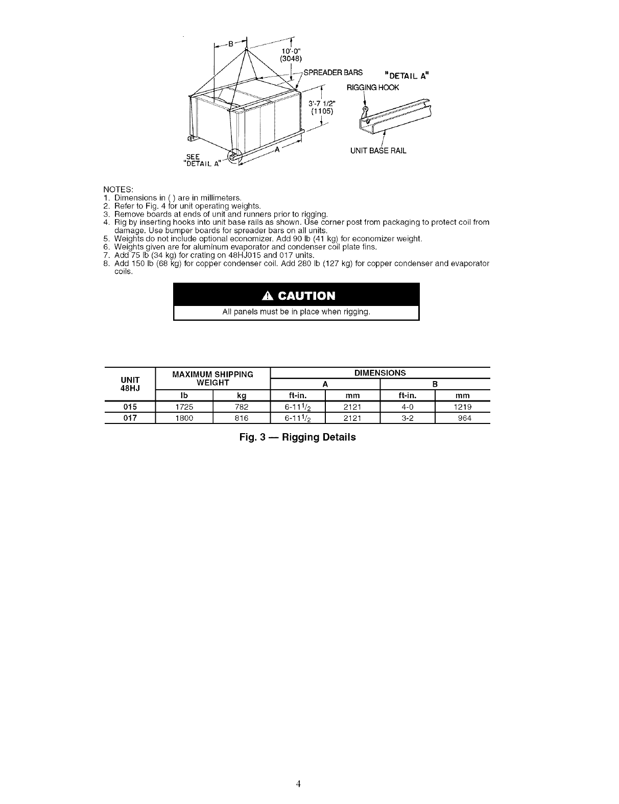
Step 2 -- Rig and Place Unit -- Do not diop unit;
keep uptight. Use spreader b_us over unit to prevent sling or
cable &image. Rollers may be used to move unit across a roof.
Level by using unit frame as a reference; leveling tolerance is
+ 1/16 in. per linear ft in any direction. See Fig. 3 for additiomfl
information. Unit operating weight is shown in Table 1.
Four lifting holes are provided in ends of unit base rails as
shown in Fig. 3. Refer to rigging instructions on unit.
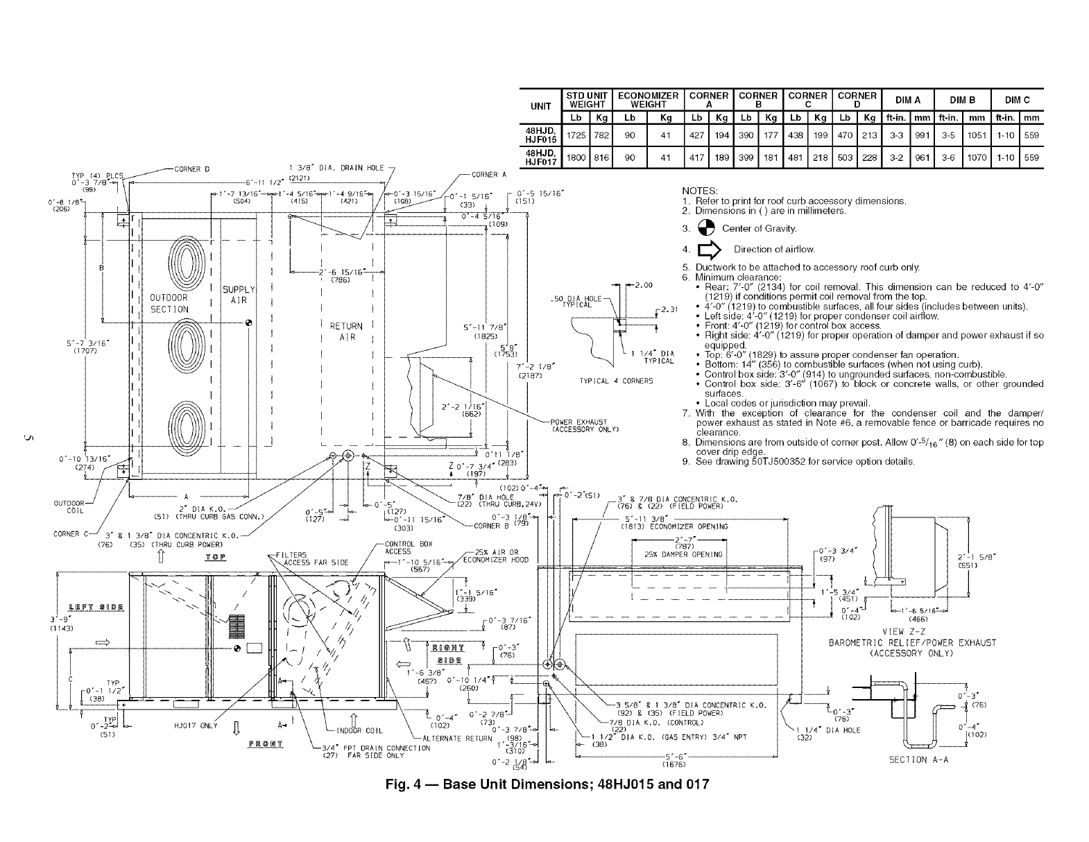
POSITIONING -- Maintain clearance, per Fig. 4, around and
above unit to provide minimum distance from combustible ma-
terials, proper airflow, and service access.
Do not install unit in an indoor location. Do not locate air in-
lets near exhaust vents or other sources of contmninated all: For
proper unit operation, adequate combustion and ventilation air
must be provided in accordance with Section 5.3 (Air for Com-
bustion and Ventilation) of the National Fuel Gas Code, ANSI
Z223.1 (American National Stan&trds Institute).
Although unit is weatherproof, guard against water from
higher level runoff and overhangs.
Ix)cate mechanical diafl system flue assembly at least 4 ft
from any opening through which combustion products could
enter the building, and at least 4 fl from any adjacent building.
When unit is located adjacent to public walkways, flue assem-
bly must be at least 7 ft above grade.
ROOF MOUNT -- Check building codes for weight
distribution requirements. Unit operating weight is shown in
Table 1.
hlstructions continued on page 7.
14-314 _
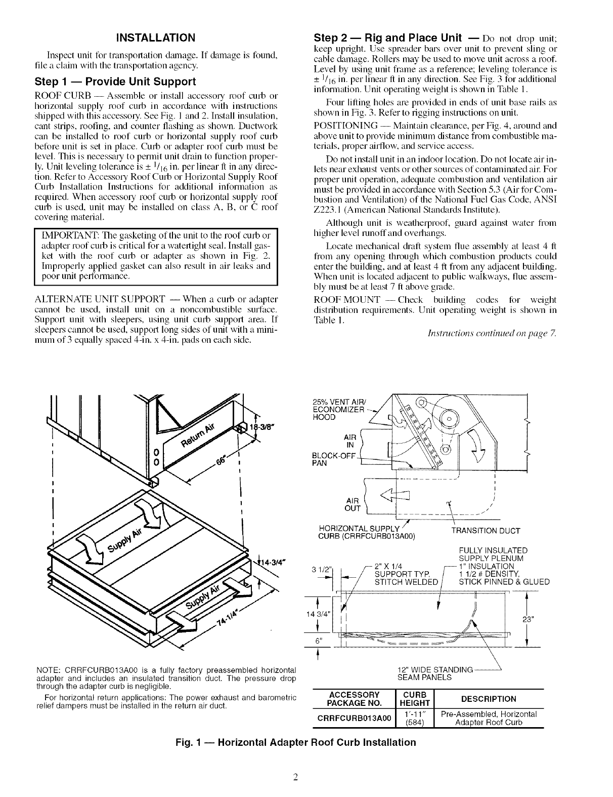
NOTE: CRRFCURB013A00 is a fully factory preassembled horizontal
adapter and includes an insulated transition duct. The pressure drop
through the adapter curb is negligible.
For horizontal return applications: The power exhaust and barometric
relief dampers must be installed in the return air duct.
25% VENTAIR/ //
ECONOMIZER--_
HOOD _._
BLOCK-OFF.J,_t
PAN
[
HORIZONTALSUPPLY_ .... -\-
TRANSITIONDUCT
CURB (CRRFCURB013A00)
6"
FULLYINSULATED
SUPPLYPLENUM
.,,_- 2" X 1/4 r_ 1" INSULATION
SUPPORTTYP. /1 1/2# DENSITY,
STITCHWELDED/STICK PINNED& GLUED
¢
-- [ ]_ /
\
12" WIDE STANDING
SEAM PANELS
ACCESSORY CURB
PACKAGE NO. HEIGHT
1'-11"
CRRFCURB013A00 (584
DESCRIPTION
Pre-Assembled, Horizontal
Adapter Roof Curb
Fig. 1 -- Horizontal Adapter Roof Curb Installation
%.J
CURB
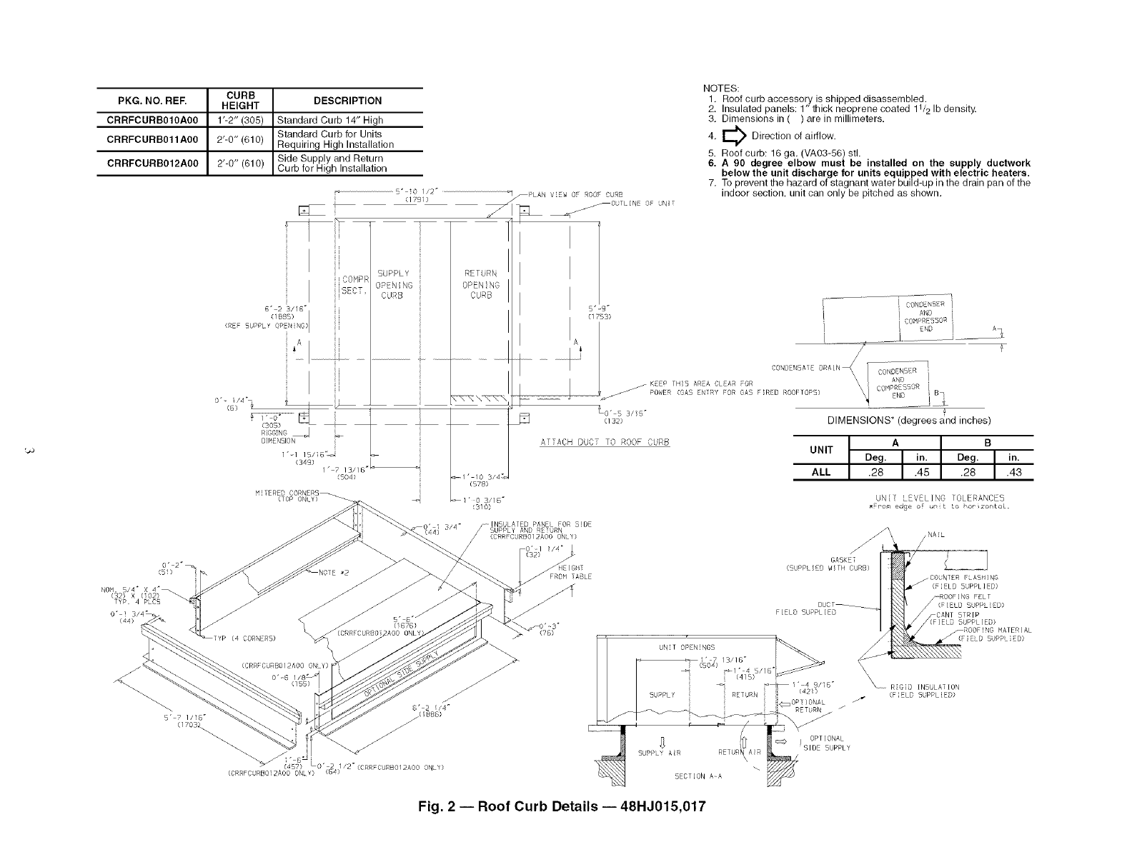
PKG. NO. REF. HEIGHT DESCRIPTION
CRRFCURB010A00 1"-2" (305) Standard Curb 14" High
Standard Curb for Units
CRRFCURB011A00 2"-0" (610) Requiring High Installation
CRRFCURBO12A00 2'-0" (610) Side Supply and Return
Curb for High Installation
5"_i0 //2 _
(1791) _PLAN ViEW OF ROOF CURB
_OUILINE OF UNIT
NOTES:
1, Roof curb accessory is shipped disassembled.
2. Insulated panels: 1" thick neoprene coated 11/2 Ib density.
3, Dimensions in ( ) are in millimeters.
Direction of airflow.
4.
5. Roof curb: 16 ga. (VA03-56) stl.
6. A 90 degree elbow must be installed on the supply ductwork
below the unit discharge for units equipped with electric heaters.
7. To prevent the hazard of stagnant water build-up in the drain pan of the
indoor section, unit can only be pitched as shown.
SUPPLY RETURN
OPENING
CURB
(REF 5UPPLY OP N NG)
I
L
1 " 1 /5/iD_
(349) L
/" 7 /3/5
(B04)
MITERED CORNERS
(TOP ONLY)_
"ZNN \ NN\
1" 10 3/4
(578)
/ 0 3//6
(310)
! i CON_ENSE_i
i AND i
/i i COHPRESBOR
/L_
CONDENSATE DRAIN X_ [ rR 7
CONDENSE ¸
AND !
j KEEP TH_5 AREA CLEAR FOR COlflPBEBSOR /
POWER (GAB ENTRY FOR GAB FIRED BBOFTOPS) END i B,
[_ _!__
to" B 3/ID" T
c/s2} DIMENSIONS* (degrees and inches)
ATTACH DUC] 10 ROOF CURB
UNIT Deg. A in. Deg. Bin.
ALL .28 .45 .28 .43
UNH LEVELING TOLERANCES
• Fpom edge oF u_{t to hoe_zor/toL.
/-[NBULAFED PANEL FOR SiDE
TYP. 4 PLCS
0"i
Fig. 2 -- Roof Curb Details -- 48HJ015,017
SEE
"DETAIL A'
SPREADERBARS "DETAIL A"
RIGGINGHOOK
(1105)
_._ )_ UNIT BASE RAIL
NOTES:
1. Dimensions in ( ) are in millimeters.
2. Refer to Fig. 4 for unit operating weights.
3. Remove boards at ends of unit and runners prior to rigging.
4. Rig by inserting hooks into unit base rails as shown. Use corner post from packaging to protect coil from
damage. Use bumper boards for spreader bars on all units.
5. Weights do not include optional economizer. Add 90 Ib (41 kg) for economizer weight.
6. Weights given are for aluminum evaporator and condenser coil plate fins.
7. Add 75 Ib (34 kg) for crating on 48HJ015 and 017 units.
8. Add 150 Ib (68 kg) for copper condenser coil. Add 280 Ib (127 kg) for copper condenser and evaporator
coils.
All panels must be in place when rigging.
UNIT
48HJ ft-in.
015 6-111/2
017 6-111/2
MAXIMUM SHIPPING
WEIGHT
Ib kg
1725 782
1800 816
DIMENSIONS
A
l mm ft-in.
2121 4-0
2121 3-2
B
mm
1219
964
Fig. 3 -- Rigging Details
STD UNIT ECONOMIZER CORNER CORNER CORNER CORNER DIM A DIM B DIM C
UNIT WEIGHT WEIGHT A B C D
Lb Kg Lb Kg Lb Kg Lb Kg Lb Kg Lb Kg ft-in, mm ft-in, mm ft-in, mm
48HJD,
HJF015 1725 782 90 41 427 194 390 177 438 199 470 213 3-3 991 3-5 1051 1-10 559
48HJD,
HJF017 1800 816 90 41 417 189 399 181 481 218 503 228 3-2 961 3-8 1070 1-10 559
CORNER D 1 3/8" D}A, DRAIN HOLE
TYP C4) PLC5 (2121) CORNER A
(99) / \1 _1"-7 13/16"_1"-4 5/16_1"-4 9/16r_l /_0"-3 15/16_0. 1 _/)_- F O'-S 15/16" NOTES;
o"-a we_, \1 (so4) / (4_s_ / (42_) // n08_///+i_ ]_3_ ° 1051) 1. Refer to print for roof curb accessory dimensions.
c2o_) | I _ | I V / '_ __+_ '_ _ 2 D mens ons n ( ) are n m meters
r [/ --4 .
3. _ Center of Gravity.
YI li',1 -- t: , 4. Directionofairflow.
I D Ii_l ttttt)))/) I / I _J'6 15/16" I //// 5. Ductwork to be attached to accessory roof curb only.
/I I I it \\_/// I / ' , -(78e) _//// 6. Minimum clearance:
|1 I', li _ ]SUPPLYI I I ///| _ 1"-2,00 • Rear: 7'-0" (2134) for coil removal. This dimension can be reduced to 4'-0"
/I II II OUTDOOR- I AIR / , I ///| .50 DIA HOLE_ I | 1219 if conditions permit coil removal from the top.
/I II it SECTION I " / _ I I //// TYPICAL \ I/ 2 s_ • 4'-O" (1219) to combustible surfaces all four sicles (includes between units),
/ l I' II ...... _ I I @/ I I /|// \11 1-" • Left side: 4'-O" (1219) forpropercon'densercollalrflow.
| II i1 /_\ / RETURN / 5"-H 7/8"1/ £ [_g::]r------i • Front: 4'-0" (1219)for control box access.
| I rl /llfl_\k\\ I I I/ ' AIR / (1825)-I/ _ _ _ •Right side: 4'-O" (1219) for proper operation of damper and power exhaust if so
5"_]_D" IIll 1(((]l//i I I/ I ''_---J -5)R"I ) I \ .equipped.
II ,t t\\\\ Jill/ 1 I _ _ (17s3) I k I L 1 1/4- DIA "Top 6'-0" 1829 to assure proper condenser fan operaton
IYi li _J ]I I/ I I I -- __ I I 7"-2 1/8" _ TYPICAL " Bottom:14" (356) to combustible surfaces (when not using curb).
I I III _ I I I 1 I /I _ I I I (21D7) TYPICAL 4 CDR ER5 • Control box side: 3"-0" (914) to ungrounded surfaces, non-combustible.
N
h 't | I \ I I _ I •Control box side: 3'-6" (1067) to block or concrete ,,vails, or other grounded
I' II I / I I /I I _"7"-..J surfaces
]1 II _ | I \ I I .... /,_-l""--_l • Loca codesorjursdctonmaypreva
I I
h It I/_X\ I I/ I /I I _z(6S2_ I _ 7, With the exception of clearance for the condenser coil and the damper/
I I' II ffftf ///// _ I I / i ' ( I J I I I I _POWER EXHAUST power exhaust as stated in Note #6, a removable fence or barricade requires no
/II ,t ttttt ]HI/' I I/ ' ]I _ _ I I I (ACCESSORY ONLY) clearance
_ I',II \\\\Wj//ll 1 I I I .... - -- -_ l _ I 8, Dimensions are from outside of corner post. AIIowO'-5/10"(8) oneachsidefortop
I {1 /1 " I I II '_ _ -- _1-- ,=_-_ _--_'_/_'1 cover drip edge.
D'- 0 3, 6j;qC_l it | H /J_'_'/'#'_/ _v_""_--_ Zo'-7 "_/_4"(2__)" I 9 Seedrawng5OTd5OO352forservceoptondeta s
(27_) /I_::_:_' II 1 i i / / i i L_Z0"-7 314- "_'_" I
_LLJ'n'I II / /I I I1 Z_''--, i <IDv_ _
/ 71 I// I I IL-LA"_"_'__ _' ()o2)o'-4=
A _ /7/8" DIA HOLE - 0"-2"(51) " 7/ A N TRI K
. _ 3 _ BDI C0CENc .0,
OOTDOORS/_'_--A<'_'" /_IJLo._5-_\,..)(.HROEURO.,,V_r7 ,-(,D_<(,,).E_DPO_R_ .-.
COIL _: ui .u. O'-D_4 _ (1277 I t /
/<5,)(_RRU'_OROOASCONN.)/ 0;s.)_ d_/'_,,,s._.-_... o.-3,,o-_ _ _ ,._,,3,D- ., (I1__
-('303)...... _CDRNER B (79) (1D13) ECONOMIZER OPENING
CDRNERWs"<,5'O'O,ACONCEN='C<O_-- III/.I _HI h
(76) (35) (THRU CURS POWER) CONTROL DOX (27877)
•.o. .P,L,ERS --ACCE55.--.5.A,RORIIII PERO I ?III II.!,s.o-
U-- "_ACCE55FAR51DE/lO S/15W ECONOMIZERHOOD II I /. I -- 7 ..... ] I / (9 /III I I (_5'_
-It 'XLb< ...... :h_ _ /-- z2 I "=1 5/)5" I 1"-5 3/4"
(1143) I Nil _ f'--'_ \ 1, II ___ (87) IV / VIEW ZZ
/I A /
=> III/ _ ,' ' \, _ __ I/I I I I BAROHETRIC RELIEF/POWER EXHAUST
r_ Iltl- @ LJ _ / /'*,7 II /-- ' r _fl I I / (ACCESSORYONLY)
LL_ _ _" =[ --- \"--,_,D'=13,='OIACONCENTRIC<.O./'-+'_ _n _:=4'(;=,
'_ I I A _L O" 4" 0"-2 7 _ (92 8 3S P ELOPO_ER ( _0"-5" t II t ?f
O'-;Y_JL Hi01? ONLY S A'' L]EO,L (,0.,(..) _,_SS)O,A<.O.(EO=ROL) \''"O';70;OLE-IF II0%,
(517 ALTER ATE RETURN 1 112" DIA K.O. (GAS ENTRY) 3/4" NPT (32) M _ j
,*@*lr -5/4" FFPTRO_[AD]ENCONNECT,ON N (510) _ (58) j _ ,
@7) ONLY 0"-2 (15/4_'_J (_67S6{ SECT ION A-A
Fig. 4 -- Base Unit Dimensions; 48HJ015 and 017
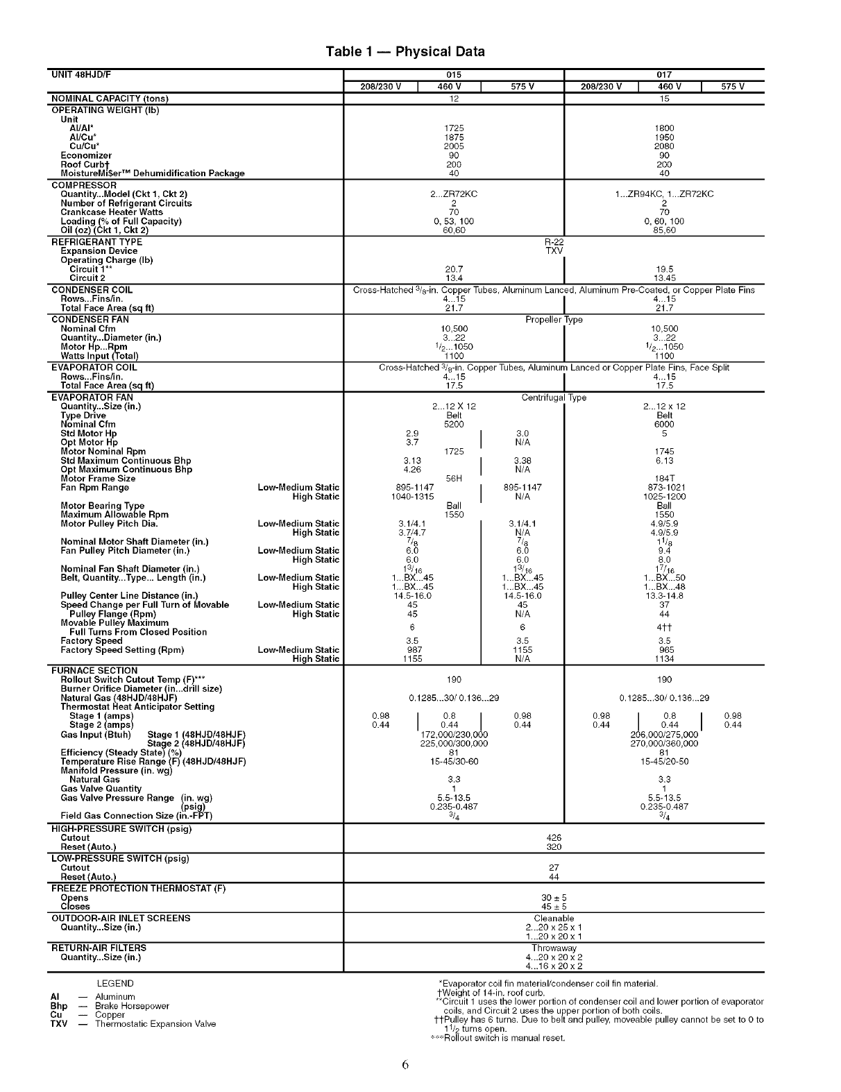
Table1 -- Physical Data
UNIT 48HJD/F 015 017
208/230 V I 460 V I 575 V 208/230 V I 460 V I 575 V
m m m m
12 15
NOMINAL CAPACITY (tons)
OPERATING WEIGHT (Ib)
Unit
AI/AI*
AI/Cu*
Cu/Cu*
Economizer
Roof Curb'j-
MoistureMi$er TM Dehumidification Package
COMPRESSOR
Quantity...Model (Ckt 1, Ckt 2)
Number of Refrigerant Circuits
Crankcase Heater Watts
Loading (% of Full Capacity)
Oil (oz) (Ckt 1, Ckt 2)
REFRIGERANT TYPE
Expansion Device
Operating Charge (Ib)
Circuit 1"*
Circuit 2
CONDENSER COIL
Rows...Fins/in.
Total Face Area (sq ft)
CONDENSER FAN
Nominal Cfm
Quantity...Diameter (in.)
Motor Hp...Rpm
Watts Input (Total)
EVAPORATOR COIL
Rows...Fins/in.
Total Face Area (sq ft)
EVAPORATOR FAN
Quantity...Size (in.)
VoPeDrive
minal Cfm
Std Motor Hp
Opt Motor Hp
Motor Nominal Rpm
Std Maximum Continuous Bhp
Opt Maximum Continuous Bhp
Motor Frame Size
Fan Rpm Range
1725 1800
1875 1950
2005 2080
90 90
200 200
40 40
2...ZR72KC 1...ZR94KC, 1...ZR72KC
2 2
70 70
0, 53, 100 0, 60, 100
80,60 85,60
R-22
TXV
20.7 I 19.5
13.4 13.45
Cross-Hatched 3/8-in. Copper Tubes, Aluminum Lanced, Aluminum Pre-Coated, or Copper Plate Fins
4...15 I 4...1521.7 21.7
Propeller Type
I0,500 I I0,500
3...22 1 3._22
1/2...1050 1/2...1050
1100 1100
Cross-Hatched 3/8-in. Copper Tubes, Aluminum Lanced or Copper Plate Fins, Face Split
4._15 [ 4-.1517.5 17.5
Centrifugal Type
Motor Bearing Type
Maximum Allowable Rpm
Motor Pulley Pitch Dia.
Nominal Motor Shaft Diameter (in.)
Fan Pulley Pitch Diameter (in.)
Nominal Fan Shaft Diameter (in.)
Belt, Quantity...Type... Length (in.)
Pulley Center Line Distance (in.)
Speed Change per Full Turn of Movable
Pulley Flange (Rpm)
Movable Pulley Maximum
Full Turns From Closed Position
Factory Speed
Factory Speed Setting (Rpm)
FURNACE SECTION
Rollout Switch Cutout Temp (F)***
Burner Orifice Diameter (in...drill size)
Natural Gas (48HJD/48HJF)
Thermostat Heat Anticipator Setting
Stage 1 (amps)
Stage 2 (amps)
Gas Input (Btuh) Stage 1 (48HJD/48HJF)
Stage 2 (48HJD/48HJF)
Efficiency (Steady State) (%)
Temperature Rise Range (F) (48HJD/48HJF)
Manifold Pressure (in. wg)
Natural Gas
Gas Valve Quantity
Gas Valve Pressure Range twu,'/in_iw_g)
Field Gas Connection Size (in.-FPT)
HIGH-PRESSURE SWITCH (psig)
Cutout
Reset (Auto.)
LOW-PRESSURE SWITCH (psig)
Cutout
Reset (Auto.)
FREEZE PROTECTION THERMOSTAT (F)
Opens
Closes
OUTDOOR-AIR INLET SCREENS
Quantity...Size (in.)
Low-Medium Static
High Static
Low-Medium Static
High Static
Low-Medium Static
High Static
Low-Medium Static
High Static
Low-Medium Static
High Static
Low-Medium Static
High Static
0.98
0.44
2.9
3.7
3.13
4.26
895-1147
1040-1315
2...12 X 12
Belt
5200
1725
55H
Ball
1550
3.1/4.1
3.7/4.7
7/8
6.0
6.0
13/16
1,,.BX...45
1,,.BX.,.45
14.5-16.0
45
45
6
3.5
987
1155
190
0.1285...30/ 0.136...29
I 0.80.44 I
172,000/230,000
225,000/300,000
81
15-45/30-80
3.3
1
5.5-13.5
0.235-0.487
3/4
l 3.0N/A
l 3.38N/A
l 895-1147N/A
3.1/4.1
N/A
7&
6.0
6.0
13/16
1...BX...45
1...BX...45
14.5-16.0
45
N/A
6
3.5
1155
N/A
0.98
0.44
426
320
27
44
30-+5
45_+5
Cleanable
2...20 x 25 x 1
1...20 x 20 x 1
RETURN-AIR FILTERS Throwaway
Quantity...Size (in.) 4...20 x 20 x 2
4...16 x 20 x 2
2...12 x 12
Belt
8000
5
1745
6.13
184T
873-1021
1025-1200
Ball
1550
4.9/5.9
4.9/5.9
11/8
9.4
8.0
17/16
1 ...BX...50
1 ...BX._48
13.3-14.8
37
44
41-1-
3.5
965
1134
190
0.1285...30/0.136...29
0.98 I 0.8 I 0.980.44 0.44 0.44
206,000/275,000
270,000/360,000
81
15-45/20-50
3.3
1
5.5-13.5
0.235-0.487
3/4
LEGEND
AI -- Aluminum
Bhp -- Brake Horsepower
Cu Copper
TXV -- Thermostatic Expansion Valve
*Evaporator coil fin material/condenser coil fin material.
1-Weight of 14-in. roof curb.
**Circuit 1 uses the lower portion of condenser coil and lower portion of evaporator
coils, and Circuit 2 uses the upper portion of both coils.
1-1-Pulley has 6 turns. Due to belt andpulley, moveable pulley cannot be set to 0 to
11/2 turns open.
_' 'Rollout switch is manual reset.
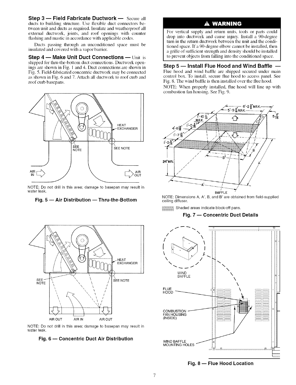
Step 3 -- Field Fabricate Ductwork -- Secure all
ducts to building structure. Use flexible duct connectors be-
tween unit and ducts as required. Insulate and weatherproof all
external ductwork, joints, and roof openings with counter
flashing and mastic in accordance with applicable codes.
Ducts passing through an unconditioned space must be
insulated and covered with a vapor baniel_
Step 4 -- Make Unit Duct Connections -- Unit is
shipped for thru-the-bottom duct connections. Ductwork open-
ings are shown in Fig. 1 and 4. Duct connections are shown in
Fig. 5. Field-fabricated concentric ductwork may be connected
as shown in Fig. 6 and 7. Attach all ductwork to roof curb and
roof cm#, basepans.
For vertic_d supply and return units, tools or pmls could
diop into ductwork and cause injury, lnst_dl a 90-degree
turn in the return ductwork between the unit and the condi-
tioned space. If a 90-degree elbow cannot be installed, then
a grille of sufficient strength and density should be installed
to prevent objects from ftdling into the conditioned space.
Step 5 -- Install Flue Hood and Wind Baffle --
Flue hood and wind baffle are shipped secured under main
control box. To install, secme flue hood to access panel. See
Fig. 8. The wind baffle is then installed over the flue hood.
NOTE: When properly installed, flue hood will line up with
combustion fan housing. See Fig. 9.
HEAT
SEE NOTE
AIR
OUT
NOTE: Do not drill in this area; damage to basepan may result in
water leak,
Fig. 5 -- Air Distribution -- Thru-the-Bottom
SEE j
NOTE ",\ \ /
•, \ \ /
\\\/
\\\\ Nkxx\ \\ ]11
AIR OUT AIR IN AIR OUT
EXCHANGER
SEE NOTE
NOTE: Do not drill in this area; damage to basepan may result in
water leak.
Fig. 6 -- Concentric Duct Air Distribution
/
/
BAFFLE
NOTE: Dimensions A, A', B, and B' are obtained from field-supplied
ceiling diffuser.
Shaded areas indicate block-off pans.
Fig. 7 -- Concentric Duct Details
k,..
\/
\/
WIND
BAFFLE
COMBUSTION
FAN HOUSING
(INSIDE)
ii
\\\
\
\
\
i gk
c:=== _,_===_
WIND BAFFLE
MOUNTING HOLES
Fig. 8 -- Flue Hood Location
m
INDUCED DRAFT
MOTOR
COMBUSTION MAIN BURNER HEAT EXCHANGER
FAN HOUSING SECTION SECTION
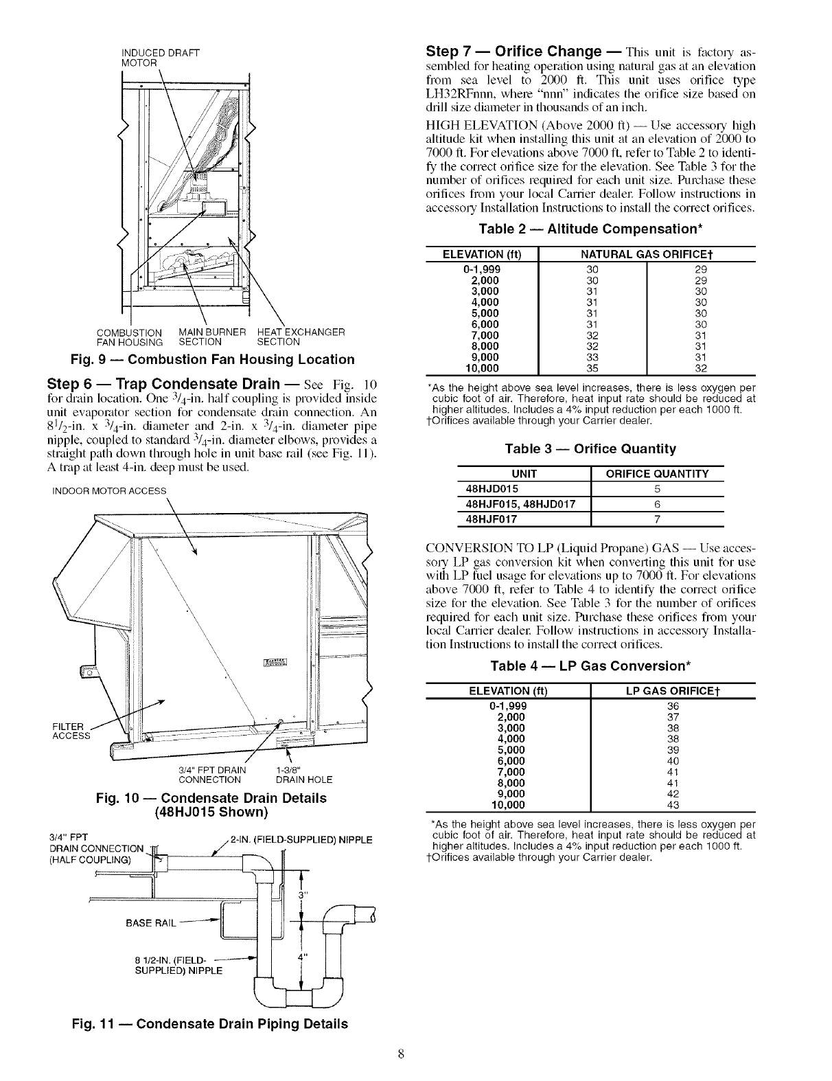
Fig. 9-- Combustion Fan Housing Location
Step 6 -- Trap Condensate Drain -- See Fig. l0
for drain location. One 3/4-in. h_df coupling is provided inside
unit evaporator section for condensate drain connection. An
81/2-in. x 3/4-in. dimneter and 2-in. x 3/4-in. diameter pipe
nipple, coupled to standard 3/4-in. diameter elbows, provides a
straight path down through hole in unit base rail (see Fig. 11).
A trap at least 4-in. deep must be used.
INDOOR MOTOR ACCESS
FILTER
ACCESS
\\\
\\
\\ \\\\\:\\\\\\\
3/4" FPT DRAIN 1-3/8"
CONNECTION DRAIN HOLE
Fig. 10- Condensate Drain Details
(48HJ015 Shown)
3/4" FPT
DRAIN CONNECTION ...ILL /2-IN
(HALF O0_ E
BASE RAIL __===
8 1/2-1N. (FIELD- ----_-'-_
SUPPLIED) NIPPLE
(FIELD-SUPPLIED) NIPPLE
Step 7 -- Orifice Change -- This unit is facto1T as-
sembled for heating operation using natund gas at an elevation
from sea level to 2000 ft. This unit uses orifice type
LH32RFnnn, where "nnn" indicates the orifice size based on
drill size diameter in thousands of an inch.
HIGH ELEVATION (Above 2000 ft) -- Use accessory high
altitude kit when inst_dling this unit at an elewttion of 2000 to
7000 ft. For elevations above 7000 ft, refer to Table 2 to identi-
fy the correct orifice size for the elevation. See Table 3 for the
number of orifices required for each unit size. Purchase these
orifices from your local Carrier dealel: Follow instructions in
accessory Installation Instructions to install the correct orifices.
Table 2 -- Altitude Compensation*
ELEVATION (ft)
0-1,999 30
2,000 30
3,000 31
4,000 31
5,000 31
6,000 31
7,000 32
8,000 32
9,000 33
10,000 35
NATURAL GAS ORIFICEt
29
29
30
30
30
30
31
31
31
32
*As the height above sea level increases, there is less oxygen per
cubic foot of air. Therefore, heat input rate should be reduced at
higher altitudes. Includes a 4% input reduction per each 1000 ft.
1-Orifices available through your Carrier dealer.
Table 3 -- Orifice Quantity
UNIT ORIFICE QUANTITY
48HJD015 5
48HJF015,48HJD017 6
48HJF017 7
CONVERSION TO LP (Liquid Propane) GAS -- Use acces-
soULP gas conversion kit when converting this unit for use
with LP fuel usage for elew_tions up to 7000 ft. For elevations
above 7000 ft, refer to Table 4 to identify the correct orifice
size for the elew_tion. See Table 3 for the number of orifices
required for each unit size. Purchase these orifices from your
loc_d Carrier dealel: Follow instructions in accessory Installa-
tion Instructions to inst:dl the correct orifices.
Table 4 -- LP Gas Conversion*
ELEVATION (ft)
0-1,999
2,000
3,000
4,000
5,000
6,000
7,000
8,000
9,000
10,000
LP GAS ORIFICEt
36
37
38
38
39
40
41
41
42
43
*As the height above sea level increases, there is less oxygen per
cubic foot of air. Therefore, heat input rate should be reduced at
higher altitudes. Includes a 4% input reduction per each 1000 ft.
1-Orifices available through your Carrier dealer.
Fig. 11 -- Condensate Drain Piping Details
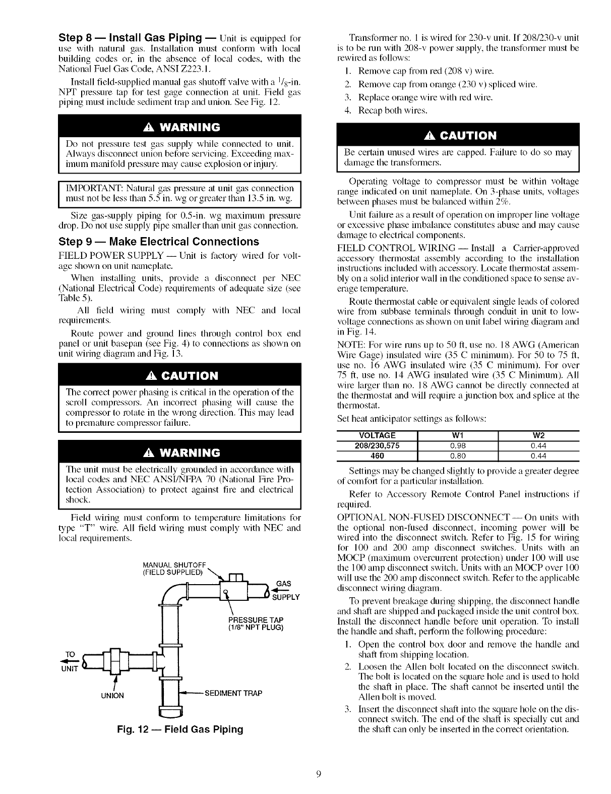
Step 8 -- Install Gas Piping -- Unit is equipped for
use with natured gas. Installation must conform with loc_d
building codes or. in the absence of loc_fl codes, with the
National Fuel Gas Code, ANSI Z223.1.
Install field-supplied manual gas shutoff valve with a I/s-in.
NPT plessure mp for test gage connection at unit. Field gas
piping must include sediment trap and union. See Fig. 12.
Tlansformer no. 1 is wired for 230-v unit. If 208/230-v unit
is to be run with 208-v power supply, the transformer must be
rewired as follows:
1. Remove cap from red (208 v) wire.
2. Remove cap from orange (230 v) spliced wire.
3. Replace orange wire with led wire.
4. Recap both wires.
Do not pressure test gas supply while connected to unit.
Always disconnect union before servicing. Exceeding max-
imum manifold pressure may cause explosion or injury.
I MPORTANT: Natural gas pressure at unit gas connection
must not be less than 5.5 in. wg or greater than 13.5 in. wg.
Size gas-supply piping for 0.5-in. wg maximum pressure
drop. Do not use supply pipe sm_dler than unit gas connection.
Step 9 -- Make Electrical Connections
FIELD POWER SUPPLY- Unit is factory wiled for volt-
age shown on unit nmneplate.
When installing units, provide a disconnect per NEC
(National Electrical Code) requirements of adequate size (see
Table 5).
All field wiring must comply with NEC and local
requirements.
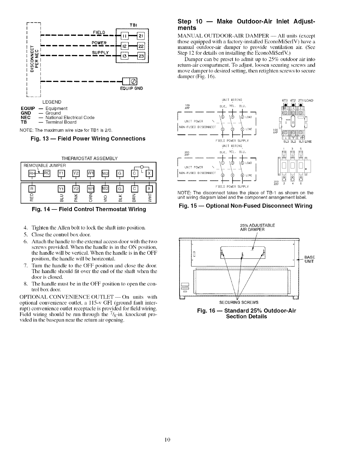
Route power and ground lines through control box end
panel or unit basepan (see Fig. 4) to connections as shown on
unit wiring diagram and Fig. 13.
The correct power phasing is critical in the operation of the
scroll compressol_. An incorrect phasing will cause the
compressor to rotate in the wrong direction. This may lead
to premature compressor failure.
The unit must be electrically grounded in accor&mce with
local codes and NEC ANSI/NFPA 70 (National Fire Pro-
tection Association) to protect against fire and electric_fl
shock.
Field wiring must conform to temperature limitations for
type "T" wire. All field wiring must comply with NEC and
loc_drequirements.
MANUAL SHUTOFF
/F,ELOST GAS
(118" NPT PLUG)
=
UNIT _ _---
u& =-"--- SEDIMENT TRAP
Fig. 12 -- Field Gas Piping
Be certain unused wires ale capped. Failure to do so may
&_magethe transformers.
Operating voltage to compressor must be within voltage
range indicated on unit nameplate. On 3-phase units, voltages
between phases must be balanced within 2%.
Unit failure as a result of operation on improper line voltage
or excessive phase imbalance constitutes abuse and may cause
&image to electrical components.
FIELD CONTROL WIRING -- Install a Carrier-approved
accessory thermostat assembly according to the installation
instructions included with accessory. Locate thermostat assem-
bly on a solid interior wall in the conditioned space to sense av-
erage temperature.
Route thermostat cable or equivalent single leads of colored
wire fiom subbase terminals through conduit in unit to low-
voltage connections as shown on unit label wiring diagram and
in Fig. 14.
NOTE: For wire runs up to 50 ft, use no. 18 AWG (American
Wire Gage) insulated wire (35 Cminimum). For 50 to 75 ft,
use no. 16 AWG insulated wire (35 Cminimum). For over
75 ft, use no. 14 AWG insulated wire (35 CMinimum). All
wire larger than no. 18 AWG cannot be directly connected at
the thermostat and will require a junction box and splice at the
thermostat.
Set heat anticipator settings as follows:
VO LTAGE W 1W2
208/230,575 0.98 0.44
460 0.80 0.44
Settings may be changed slightly to provide a greater degree
of comfolt for a palticuku installation.
Refer to Accessory Remote Control Panel instructions if
requiled.
OPTIONAL NON-FUSED DISCONNECT -- On units with
the optional non-fused disconnect, incoming power will be
wired into the disconnect switch. Refer to Fig. 15 for wiring
for 100 and 200 amp disconnect switches. Units with an
MOCP (maximum overcurrent protection) under 100 will use
the 100 amp disconnect switch. Units with an MOCP over 100
will use the 200 amp disconnect switch. Refer to the applicable
disconnect wiling diagram.
To prevent breakage during shipping, the disconnect handle
and shaft are shipped and packaged inside the unit control box.
Inst+dl the disconnect handle before unit opelation. To install
the handle and shaft, perform the following procedure:
1. Open the control box door and remove the handle and
shaft fi_>m shipping location.
2. Ix>osen the Allen bolt located on the disconnect switch.
The bolt is located on the square hole and is used to hold
the shaft in place. The shaft cannot be inserted until the
Allen bolt is moved.
3. Insert the disconnect shaft into the square hole on the dis-
connect switch. The end of the shaft is speci+dly cut and
the shaft can only be inserted in the correct orientation.
b
LUO
ZUJ
z z
0n-
ot.u
o') o,.
TBI
II FIELD i r--i rzq
_II III I III II_
L........ P_OW_ER__lc2 r=2
I
I
i
!
, r-qN
1 EQUIP GND
I
L .............. J
LEGEND
EQUIP -- Equipment
GND -- Ground
NEC -- National Electrical Code
TB -- Terminal Board
NOTE: The maximum wire size for TB1 is 2/0.
Fig. 13 -- Field Power Wiring Connections
THERMOSTAT ASSEMBLY
RE_JUM_ E_ _ _ [_
F7 m
£3 _ Z Z I--
££ ca __ 0 _ ca ca
Fig. 14 -- Field Control Thermostat Wiring
Step 10 -- Make Outdoor-Air Inlet Adjust-
ments
MANUAL OUTDOOR-AIR DAMPER -- All units (except
those equipped with a factory-insLdled EconoMiSeltV) have a
manual outdoor-air damper to provide ventilation all: (See
Step 12 for details on installing the EconoMiSerIV.)
Damper can be preset to a&nit up to 25% outdoor air into
return-air compartment. To adjust, loosen securing screws and
move dmnper to desired setting, then retighten screws to secure
damper (Fig. 16).
UNIT WIRING 6T3 4T2 2T1 LOAD
100 SLK, YEL. BLU.
{-
IN°Nu;IuTSE;°;EIRsO°NNEc\T___ ______L]NEJ
FIELD POWER 5UPPLY 5L3 3L2 1L1 LINE
UNIT WIRING
200 BLK. YEL. BLU=
[ UNIT POWER \ \C) \@ \@LOAD [
'N°'FUSEOOI'OONNECTL LI _"E]--
FIELD POWER SUPPLY
NOTE: The disconnecttakestheplaceofTB-I as shown on the
unitwiring diagram label and the component arrangement label.
Fig. 15- Optional Non-Fused Disconnect Wiring
4. Tighten the Allen bolt to lock the shaft into position.
5. Close the control box dool:
6. Attach the handle to the external access door with the two
screws provided. When the handle is in the ON position,
the handle will be vertical When the handle is in the OFF
position, the handle will be horizontal.
7. Turn the handle to the OFF position and close the dool:
The handle should fit over the end of the shall when the
door is closed.
8. The handle must be in the OFF position to open the con-
trol box door
OPTIONAL CONVENIENCE OUTLET-- On units with
optiomd convenience outlet, a 115-v GF[ (ground fault inter-
rupt) convenience outlet receptacle is provided for field wiring.
Field wiring should be run through the 7/s-in. knockout pro-
vided in the basepan near the return air opening.
25% ADJUSTABLE
AIR DAMPER
SECURING SCREWS
Fig. 16 -- Standard 25% Outdoor-Air
Section Details
BASE
UNIT
10
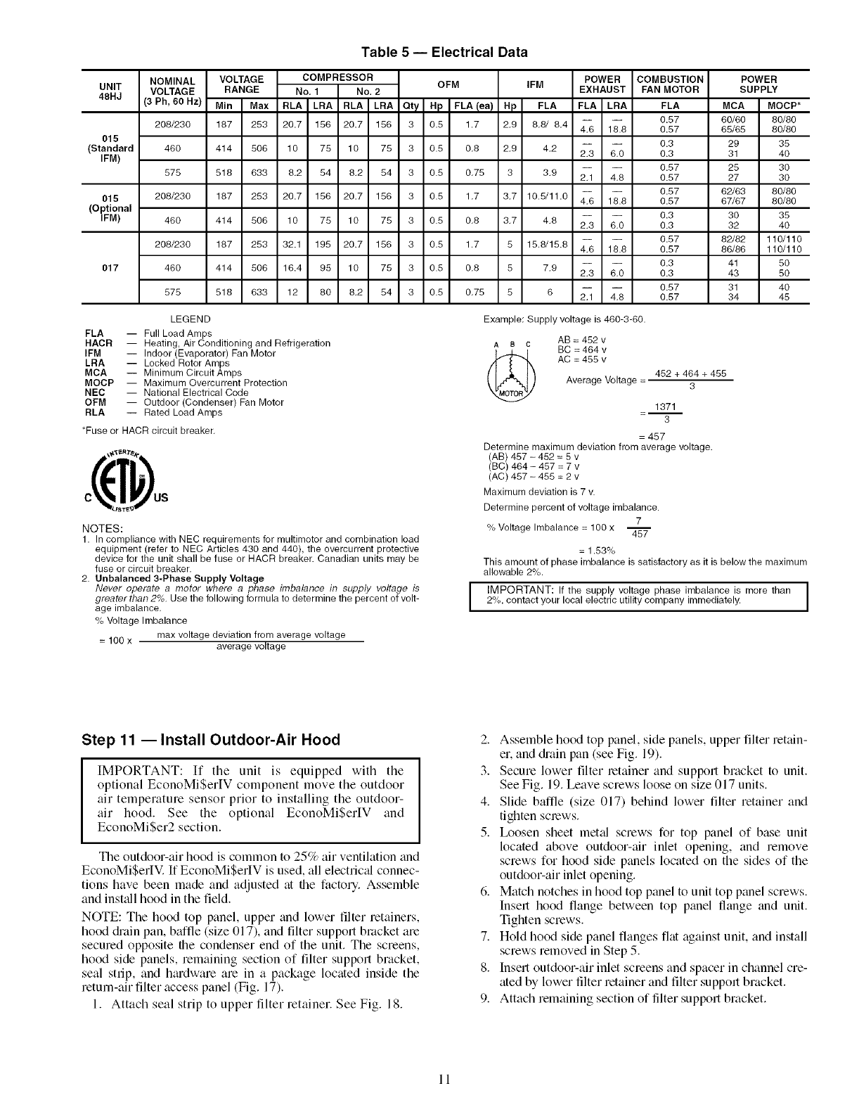
Table 5 -- Electrical Data
UNIT
48HJ
015
(Standard
IFM)
015
(Optional
IFM)
017
NOMINAL
VOLTAGE
(3 Ph, 60 Hz)
208/230
480
575
208/230
480
208/230
48O
575
VOLTAGE
RANGE
Min Max
187 253
414 508
518 833
187 253
414 508
187 253
414 506
518 833
COMPRESSOR
No, 1 No, 2
RLA LRA RLA LRA
20.7 158 20.7 156
10 75 10 75
8.2 54 8.2 54
20.7 186 20.7 156
10 75 10 78
32.1 195 20.7 156
16.4 95 10 75
12 80 8.2 84
OFM
Qty Hp FkAlea !
3 0.5 1.7
3 0.5 0.8
3 0.5 0.75
3 0.5 1.7
3 0.5 0.8
3 0.5 1.7
3 0.8 0.8
3 0.8 0.75
IFM
Hp FLA
2.9 8.8/ 8.4
2,9 4,2
3 3,9
3.7 10.5/11.0
3.7 4.8
5 15.8/15.8
5 7,9
8 6
POWER
EXHAUST
FLA LRA
4.6 18.8
2.3 6.0
2.1 4.8
4.6 18.8
2.3 8.0
4.8 18.8
2.3 8.0
2.1 4.8
COMBUSTION
FAN MOTOR
FLA
0.57
0.57
0.3
0.3
0.57
0.57
0.57
0.57
0.3
0.3
0.57
0.57
0.3
0.3
0.57
0.57
POWER
SUPPLY
MCA MOCP*
60/60 80/80
65/65 80/80
29 35
31 40
28 30
27 30
82/83 80/80
87/87 80/80
30 35
32 40
82/82 110/110
88/88 110/110
41 50
43 50
31 40
34 45
LEGEND
FLA -- Full Load Amps
HACR -- Heating, Air Conditioning and Refrigeration
IFM -- Indoor (Evaporator) Fan Motor
LRA -- Locked Rotor Amps
MCA -- Minimum Circuit Amps
MOCP -- Maximum Overcurrent Protection
NEC -- National Electrical Code
OFM -- Outdoor (Condenser) Fan Motor
RLA -- Rated Load Amps
*Fuse or HACR circuit breaker,
_ST_
NOTES:
1. In compliance with NEC requirements for multimotor and combination load
equipment (refer to NEC Articles 430 and 440), the overcurrent protective
device for the unit shall be fuse or HACR breaker. Canadian units may be
fuse or circuit breaker.
2. Unbalanced 3-Phase Supply Voltage
Never operate a motor where a phase imbalance in supply voltage is
greater than 2%. Use the following formula to determine the percent of volt-
age imbalance,
% Voltage Imbalance
= 100 x max voltage deviation from average voltage
average voltage
I
Example: Supply voltage is 460-3-60.
t, a c AB = 452 v
BC = 464 v
(_ AC =455 v
Average Voltage = 482 + 464 + 455
3
1371
=-- 3
= 457
Determine maximum deviation from average voltage.
(AB) 487 - 482 = 8 v
(BC) 464 - 487 = 7 v
(AC) 487 - 488 = 2 v
Maximum deviation is 7 v.
Determine percent of voltage imbalance.
7
% Voltage Imbalance = 100 x 48"7
= 1.53%
This amount of phase imbalance is satisfactory as it is below the maximum
allowable 2%.
IMPORTANT: If the supply voltage phase imbalance is more than I
2%, contact your local electric utility company immediately. I
Step 11 --Install Outdoor-Air Hood
IMPORTANT: If tile unit is equipped with tile
optional EconoMiSer[V component move tile outdoor
air temperature sensor prior to installing the outdoor-
air hood. See the optional EconoMiSerIV and
EconoMiSer2 section.
The outdoor-air hood is common to 25% air ventilation and
EconoMiSerIV. If EconoMiSerIV is used, all electric_fl connec-
tions have been made and adjusted at file factory. Assemble
and inst_fll hood in the field.
NOTE: The hood top panel, upper and lower filter retainers,
hood c.hain pan, baffle (size 017), and filter support bracket are
secured opposite file condenser end of the unit. The screens,
hood side panels, remaining section of filter support bracket,
seal strip, and hmdware are in a package located inside tile
return-air filter access panel (Fig. 17).
1. Attach seal strip to upper filter retainer. See Fig. 18.
2. Assemble hood top panel, side panels, upper filter retain-
er, and c.hain pan (see Fig. 19).
3. Secure lower filter retainer and support bracket to unit.
See Fig. 19. Leave screws loose on size 017 units.
4. Slide baffle (size 017) behind lower filter retainer and
tighten screws.
5. Ix)osen sheet metal screws for top panel of base unit
located above outdoor-air inlet opening, and remove
screws for hood side panels located on tile sides of tile
outdoor-air inlet opening.
6. Matcll notches in hood top panel to unit top panel screws.
Insert hood flange between top panel flange and unit.
Tighten screws.
7. Hold hood side panel flanges flat against unit, and install
screws removed in Step 5.
8. Insert outdoor-air inlet screens and spacer in channel cre-
ated by lower filter retainer and filter support bracket.
9. Attach remaining section of filter support bracket.
11
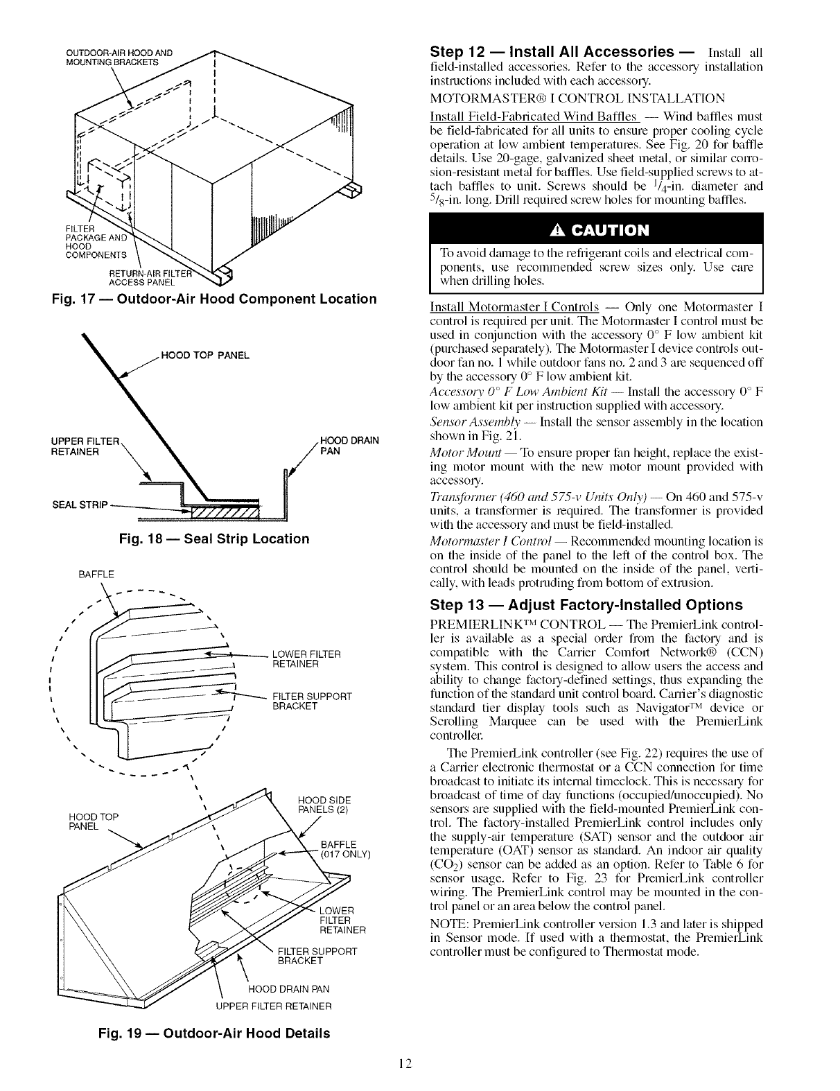
OUTDOOR*AIR HOOD AND
MOUNTING BRACKETS Step 12 -- Install All Accessories -- Install all
field-installed accessories. Refer to the accessory installation
instructions included with each accessory.
MOTORMASTER® I CONTROL INSTALLATION
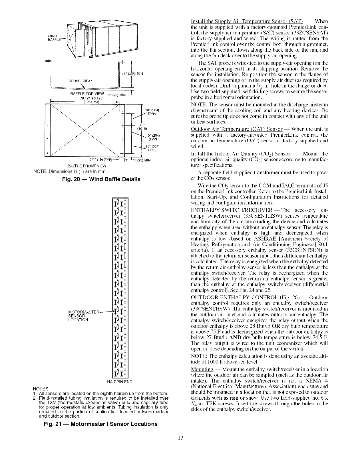
Install Field-Fabricated Wind Baffles -- Wind baffles must
be field-fabricated for all units to ensure proper cooling cycle
opelation at low ambient temperatures. See Fig. 20 for baffle
details. Use 20-gage, galwmized sheet metal, or similtu corro-
sion-resistant meted for baffles. Use field-supplied screws to at-
tach baffles to unit. Screws should be l/4-in, diameter and
5/s-in. long. Drill required screw holes for mounting baffles.
FILTER
PACKAGEANE
HOOD
COMPONENTS
ACCESS PANEL
Fig. 17 -- Outdoor-Air Hood Component Location
PANEL
UPPER FILTER
RETAINER PAN
SEAL
Fig. 18 -- Seal Strip Location
BAFFLE
\
I
\
\
\
\
HOOD TOP
PANEL
LOWER FILTER
RETAINER
FILTER SUPPORT
BRACKET
HOOD SIDE
PANELS (2)
BAFFLE
"(017 ON LY)
LOWER
FI_ER
RETAINER
FIWER SUPPORT
BRACKET
To avoid dmnage to the refiigemnt coils and electric_d com-
ponents, use recommended screw sizes only. Use care
when drilling holes.
Install Motormaster I Controls -- Only one Motormaster I
control is required per unit. The Motormaster I control must be
used in conjunction with the accessory 0 ° F low mnbient kit
(purchased sep_uately). The Motormaster I device controls out-
door fan no. 1 while outdoor fans no. 2 and 3 are sequenced off
by the accessory 0° F low ambient kit.
Accessoiw 0°F Low Ambient Kit -- Install the accessory 0° F
low ambient kit per instruction supplied with accessory.
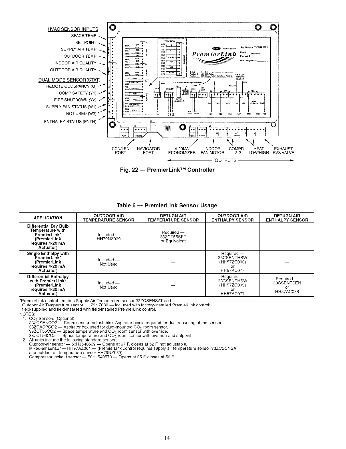
Sensor Assemb@ -- Install the sensor assembly in the location
shown in Fig. 21.
Motor Mount- To ensure proper fan height, replace the exist-
ing motor mount with the new motor mount provided with
accessoq.
Tran.ffi, rmer (460 and 575-v Units Only) -- On 460 and 575-v
units, a transformer is required. The transformer is provided
with the accessory and must be field-inst_dled.
Motormaster I Control -- Recommended mounting location is
on the inside of the panel to the left of the control box. The
control should be mounted on the inside of the panel, verti-
cally, with leads protruding from bottom of extrusion.
Step 13- Adjust Factory-Installed Options
PREM[ERLIN K TM CONTROL -- The PremierLink control-
ler is available as a special order from the factory and is
compatible with the Carrier Comfort Network® (CCN)
system. This control is designed to allow users the access and
ability to change factory-defined settings, thus expanding the
function of the standmd unit control board. Carrier's diagnostic
standard tier display tools such as Navigato/rM device or
Scrolling Marquee can be used with the PremierLink
controllel:
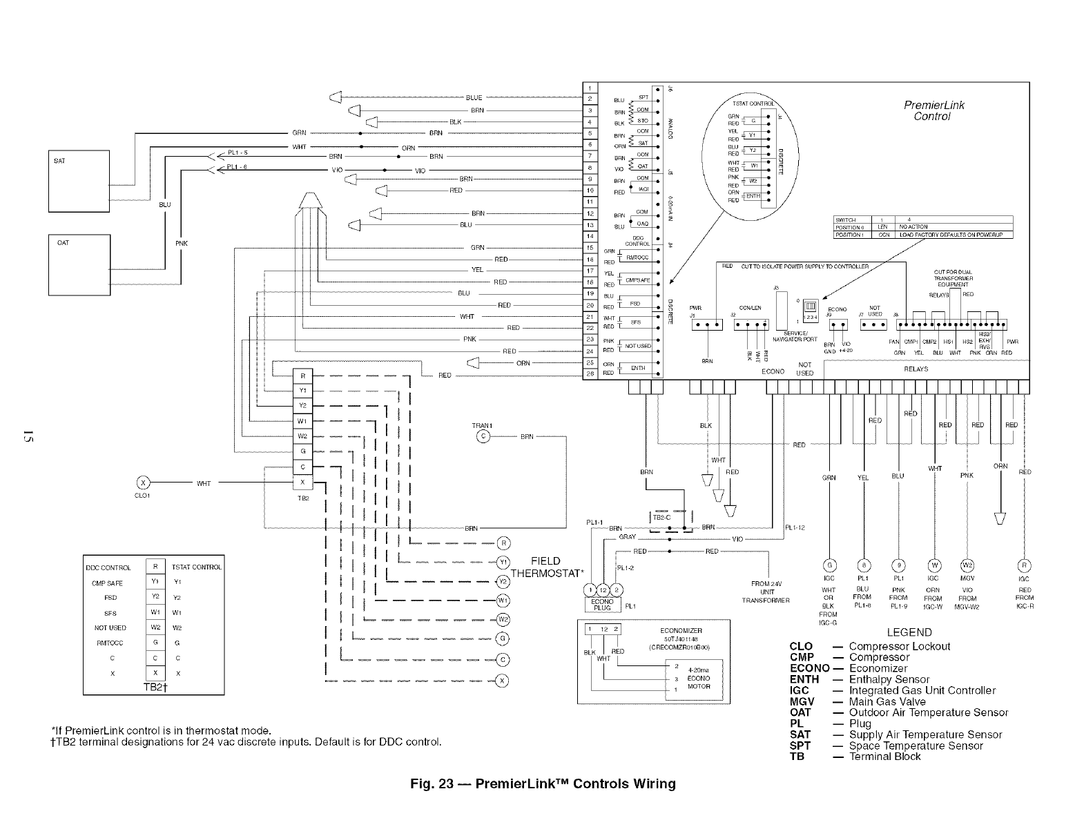
The PremierLink controller (see Fig. 22) requires the use of
a C_urier electronic thermostat or a CCN connection for time
broadcast to initiate its internal timeclock. This is necessmy for
broadcast of time of day functions (occupied/unoccupied). No
sensors are supplied with the field-mounted PremierLink con-
trol. The factory-installed PremierLink control includes only
the supply-air temperature (SAT) sensor and the outdoor air
temperature (OAT) sensor as standmd. An indoor air quality
(CO2) sensor can be added as an option. Refer to Table 6 for
sensor usage. Refer to Fig. 23 for PremierLink controller
wiring. The PremierLink control may be mounted in the con-
trol panel or an area below the control panel.
NOTE: PremierLink controller version 1.3 and later is shipped
in Sensor mode. If used with a thermostat, the PremierLink
controller must be configured to Thermostat mode.
HOOD DRAIN PAN
UPPER FILTER RETAINER
Fig. 19 -- Outdoor-Air Hood Details
12
BAFFLE TOP VIEW r' (25) MIN _
78.12" _+0,125"
t'_ (1984 -+3) /
/
÷_ +"
+ +.
. J/\ +
I
3/4" (19) (TYP)--_ _ :1"(25) MIN
BAFFLE FRONT VIEW
NOTE: Dimensions in ( ) are in mm.
Fig. 20 -- Wind Baffle Details
10"(254)
(TYP)
- 40"
1016
_10"(254)
- (TYP)
----,-q 15"(381)
__(r','P)
m
MOTORMASTER-----.-- _ _ _ :_
SENSOR _ :_:_
LOCATION
HAIRPIN END
NOTES:
1. All sensors are located on the eighth hairpin up from the bottom.
2. Field-installed tubing insulation is required to be installed over
the TXV (thermostatic expansion valve) bulb and capillary tube
for proper operation at low ambients. Tubing insulation is only
required on the portion of suction line located between indoor
and outdoor section.
Fig. 21 -- Motormaster I Sensor Locations
Install the Supply Air Temperature Sensor (SAT) -- When
the unit is supplied with a factory-mounted PlemierLink con-
trol, the supply-air temperature (SAT) sensor (33ZCSENSAT)
is factory-supplied and wired. The wiring is routed from the
PremierLink control over the control box, through a grommet,
into the fan section, down along the back side of the fan, and
_dong the fan deck over to the supply-air opening.
The SAT probe is wi_e-tied to the supply-air opening (on the
horizontal opening end) in its shipping position. Remove the
sensor for installation. Re-position the sensor in the flange of
the supply-air opening or in the supply air duct (as required by
local codes). Drill or punch a I/2-in. hole in the flange or duct.
Use two field-supplied, self-drilling screws to secme the sensor
probe in a horizontal orientation.
NOTE: The sensor must be mounted in the discharge ai_.steam
downstream of the cooling coil and any heating devices. Be
sure the probe tip does not come in contact with any of the unit
or heat surfaces.
Outdoor Air Temperature (OAT) Sensor -- When the unit is
supplied with a factoq-mounted PremierLink control, the
outdoor-air temperature (OAT) sensor is factory-supplied and
wired.
Install the Indoor Air Quality (CO2) Sensor -- Mount the
optional indoor air quality (CO2) sensor according to manufac-
turer specifications.
A separate field-supplied transformer must be used to pow-
er the CO 2 sensoc
Wire the CO 2 sensor to the COM and IAQI terminals of J5
on the PremierLink controllec Refer to the PremierLink Instal-
lation, Start-Up, and Configuration Instructions for detailed
wiring and configuration information.
ENTHALPY SWITCH/RECEIVER--The accessory en-
thalpy switchheceiver (33CSENTHSW) senses temperatme
and humidity of the air sunounding the device and calculates
the enthalpy when used without an enthalpy sensoc The _elay is
energized when enthalpy is high and deenergized when
enthalpy is low (based on ASHRAE [American Society of
Heating, Refrigeration and Air Conditioning Engineers] 90.1
criteria). If an accessoq enthalpy sensor (33CSENTSEN) is
attached to the return air sensor input, then differential enth_dpy
is c_dculated. The relay is energized when the enthalpy detected
by the return air enthalpy sensor is less than the enthalpy at the
enthalpy switch/receivec The relay is deenergized when the
enthalpy detected by the return air enth_dpy sensor is greater
than the enth_dpy at the enthalpy switch/receiver (diffe_entkd
enthalpy control). See Fig. 24 and 25.
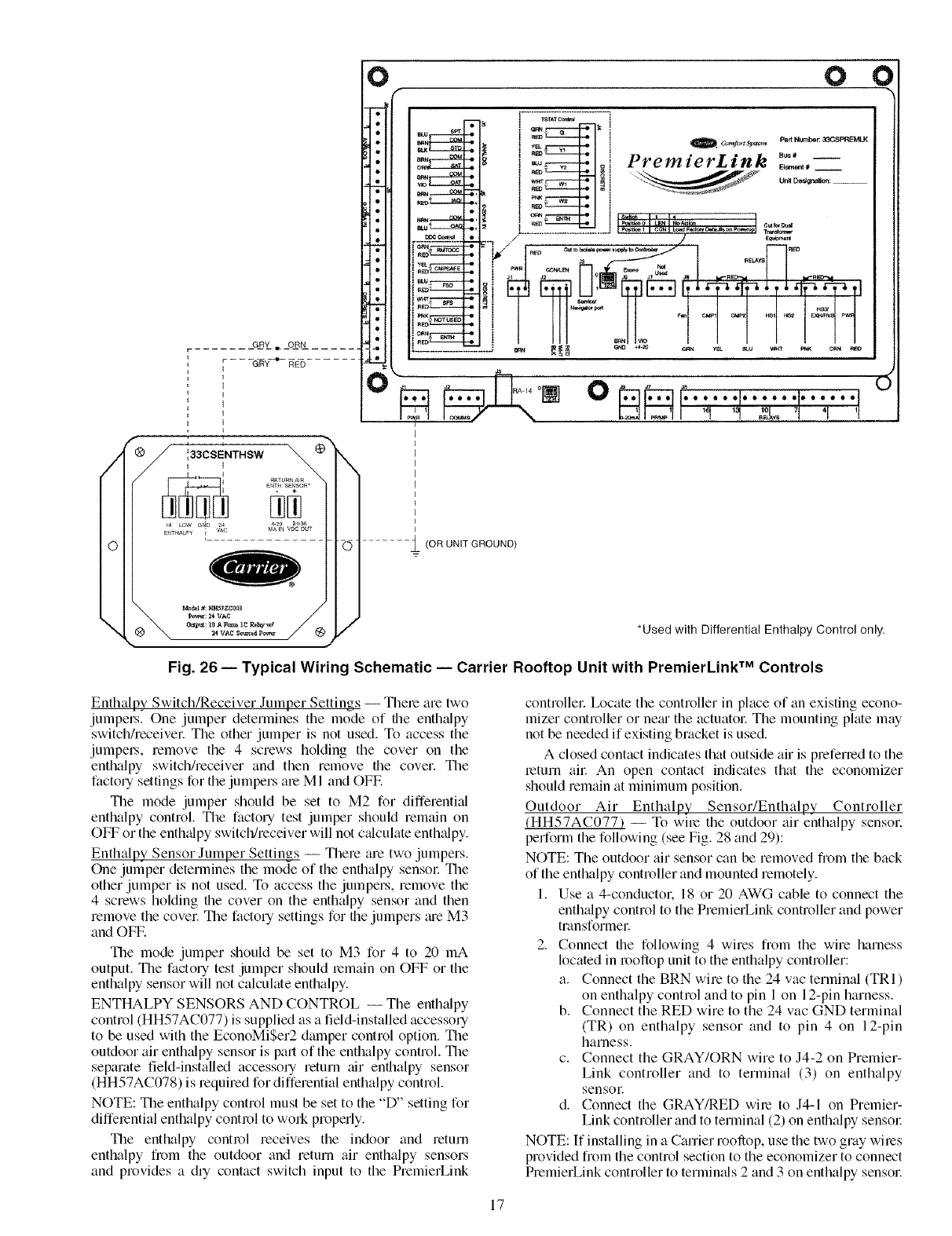
OUTDOOR ENTHALPY CONTROL (Fig. 26) -- Outdoor
enthalpy control requires only an enthalpy switch/receiver
(33CSENTHSW). The enthalpy switch/receiver is mounted in
the outdoor air inlet and c_dculates outdoor air enthalpy. The
enth_dpy switch/receiver energizes the _elay output when the
outdoor enthalpy is above 28 Btu/lb OR dry bulb temperature
is above 75 F and is deenergized when the outdoor enthalpy is
below 27 Btu/lb AND diT bulb temperature is below 74.5 E
The relay output is wired to the unit economizer which will
open or close depending on the output of the switch.
NOTE: The enthalpy calculation is done using an average alti-
tude of 1000 ft above sea level.
Mounting -- Mount the enthalpy switch/receiver in a location
where the outdoor air can be sampled (such as the outdoor air
intake). The enthalpy switchheceiver is not a NEMA 4
(Natiomd Electrical Manufactmers Association) enclosure and
should be mounted in a location that is not exposed to outdoor
elements such as rain or snow. Use two field-supplied no. 8 x
3/4-in. TEK screws. Insert the screws through the holes in the
sides of the enthalpy switchheceiver
13
HVAC SENSOR INPUTS
SPACE TEMP
SET POINT
SUPPLY AIR TEMP
OUTDOOR TEMP
INDOOR AIR QUALITY
OUTDOOR AIR QUALITY
DUAL MODE SENSOR (STAT)
COMP SAFETY (Y1) J
FIRE SHUTDOWN (Y2) //_
SUPPLY FAN STATUS (Wl)
NOT USED (W2) %
/-
ENTHALPY STATUS (ENTH) O
/f"4 "-4 "--..
CCN/LEN NAVIGATOR 4-20MA INDOOR COMPR HEAT EXHAUST
PORT PORT ECONOMIZER FAN MOTOR 1 & 2 LOW/HIGH RVS VALVE
OUTPUTS
Fig. 22 -- PremierLink TM Controller
Table 6 -- PremierLink Sensor Usage
OUTDOOR AIR RETURN AIR OUTDOOR AIR RETURN AIR
APPLICATION TEMPERATURE SENSOR TEMPERATURE SENSOR ENTHALPY SENSOR ENTHALPY SENSOR
Differential Dry Bulb
Temperature with Required --
PremierLink* Included --
(PremierLink HH79NZ039 33ZCT55SPT -- --
requires 4-20 mA or Equivalent
Actuator)
Single Enthalpy with Required --
PremierLink* Included -- 33CSENTHSW
(PremierLink Not Used -- (HH57ZC003) --
requires 4-20 mA or
Actuator) HH57AC077
Differential Enthalpy Required -- Required --
with PremierLink* Included -- 33CSENTHSW 33CSENTSEN
(PremierLink Not Used -- (HH57ZC003) or
requires 4-20 mA or HH57AC078
Actuator) HH57AC077
*PremierLink control requires Supply Air Temperature sensor 33ZCSENSAT and
Outdoor Air Temperature sensor HH79NZ039 -- included with factory-installed PremierLink control;
field-supplied and field-installed with field-installed PremierLink control.
NOTES:
1. CO2 Sensors (Optional):
33ZCSENCO2 -- Room sensor (adjustable). Aspirator box is required for duct mounting of the sensor.
33ZCASPCO2 -- Aspirator box used for duct-mounted CO2 room sensor.
33ZCT55CO2 -- Space temperature and CO2 room sensor with override.
33ZCT56CO2 -- Space temperature and CO2 room sensor with override and setpoint.
2. All units include the following standard sensors:
Outdoor-air sensor -- 50HJ540569 -- Opens at 67 F, closes at 52 F, not adjustable.
Mixed-air sensor -- HH97AZ001 -- (PremierLink control requires supply air temperature sensor 33ZCSENSAT
and outdoor air temperature sensor HH79NZ039)
Compressor lockout sensor -- 50HJ540570 --Opens at 35 F, closes at 50 R
14
SAT
GRN
WH1
_ .._./PL1 - 6
BLU
BLUE
-BRN
[_ BLK
• BRN
OAT PNK
1
WNT
CL01
DDC CONTROL R TSTAT CONTROL
CMP SAFE Y1 Y1
FSD Y2 Y2
SFS Wl Wl
NOT USED W2 W2
RMTOCC G G
C C C
X X X
TB2]
• ORN
BRN i BRN
VlO • VlO
BRN
_ RED
_ - -- BRN
_ BLU
= -- GRN
RED
_ -- YEL --
RED
- BLU
RED
= WHT
- RED
- PNK
RED
R _ RED
Y1
Y2
Wl
W2
G -- --
TB2
I
L
L
*If PremierLink control is in thermostat mode,
1-TB2 terminal designations for 24 vac discrete inputs, Default is for DDC control.
ECONOMIZER
50TJ401148
(CRECOMZR01 OBO0)
_.z L !
I 2 4-20ma
3 ECONO
1 MOTOR
L
PremierL_k
Con_ol
FROM
IGC-G LEGEND
CLO -- Compressor Lockout
CMP -- Compressor
ECONO-- Economizer
ENTH -- Enthalpy Sensor
IGC -- Integrated Gas Unit Controller
MGV -- Main Gas Valve
OAT -- Outdoor Air Temperature Sensor
PL -- Plug
SAT -- Supply Air Temperature Sensor
SPT -- Space Temperature Sensor
TB -- Terminal Block
Fig. 23 -- PremierLink TM Controls Wiring
,25'--,-
(6,35mm)
'2
L_
v
4253"
(I08 03ram)
Thermistor -_ i/i Humidity Sensor
I ==
Fig. 24 -- Enthalpy Switch/Receiver Dimensions
(33CSENTHSW)
25"--
(6.35mm)
c_;33
-4 _4
g-
4253"
(108 03mm)
33CSENTSEN
IZh 'm'st° " Hum, ,iS nso....
Fig. 25 -- Enthalpy Sensor Dimensions
(33CSENTSEN)
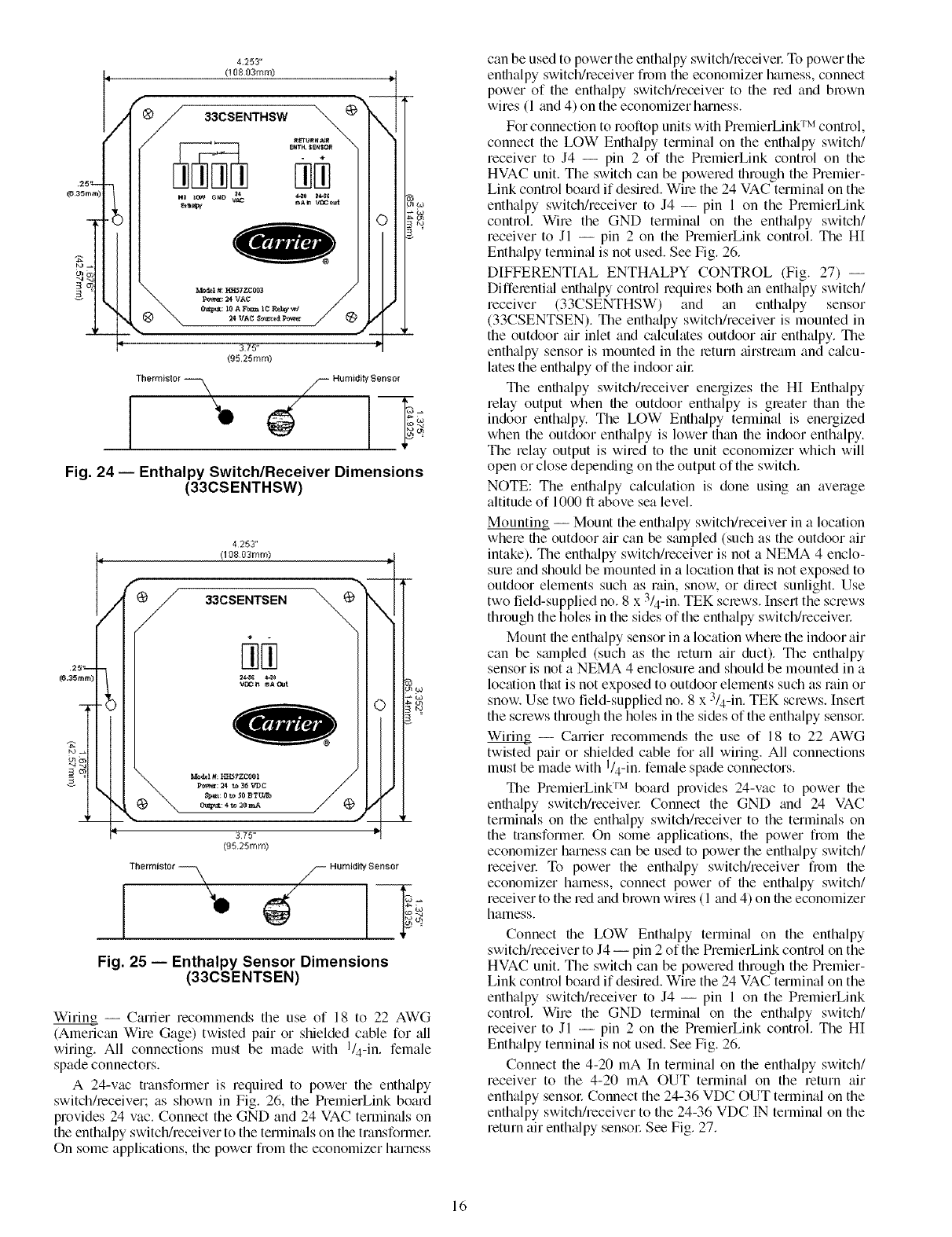
Wiring -- Career recommends the use of 18 to 22 AWG
(Americtm Wire Gage) twisted pair or shielded cable for all
wiring. All connections must be made with I/4-in. female
spade connectors.
A 24-vac transformer is required to power the enthalpy
switchheceiver; as shown in Fig. 26, the PremierLink board
provides 24 vac. Connect the GND and 24 VAC terminals on
the enthalpy switch/receiver to the terminals on the transforme_:
On some applications, the power from the economizer harness
can be used to power the enthalpy switch/receive_: To power the
enthalpy switch/receiver from the economizer harness, connect
power of the enthalpy switch/receiver to the red and brown
wires (1 and 4) on the economizer htuness.
For connection to rooftop units with PremierLink TM control,
connect the LOW Enthalpy terminal on the enthtdpy switch/
receiver to J4 -- pin 2 of the PremierLink control on the
HVAC unit. The switch can be powered through the Premier-
Link control board if desired. Wire the 24 VAC terminal on the
enthalpy switch/receiver to J4 -- pin 1 on the PremierLink
control. Wire the GND terminal on the enthalpy switch/
receiver to Jl -- pin 2 on the PremierLink control. The HI
Enthalpy terminal is not used. See Fig. 26.
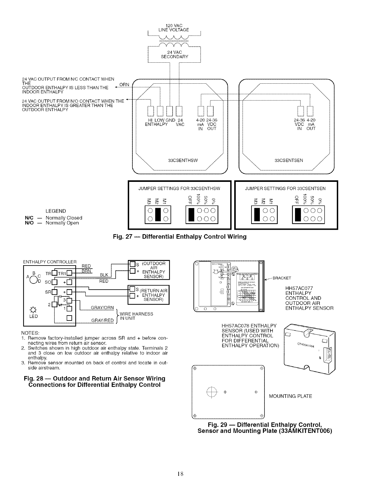
DIFFERENTIAL ENTHALPY CONTROL (Fig. 27) --
Diffe_enti_d enthalpy control requi_es both an enthalpy switch/
receiver (33CSENTHSW) and tin enthalpy sensor
(33CSENTSEN). The enthalpy switch/receiver is mounted in
the outdoor air inlet and calculates outdoor air enthalpy. The
enthalpy sensor is mounted in the return airstream and calcu-
lates the enthalpy of the indoor ai_:
The enthalpy switch/receiver energizes the H[ Enthalpy
relay output when the outdoor enthalpy is greater than the
indoor enthalpy. The LOW Enthalpy terminal is energized
when the outdoor enthalpy is lower than the indoor enthalpy.
The relay output is wired to the unit economizer which will
open or close depending on the output of the switch.
NOTE: The enth_dpy calculation is done using an average
altitude of 1000 ft above sea level.
Mounting -- Mount the enthalpy switch/receiver in alocation
where the outdoor air can be smnpled (such as the outdoor air
intake). The enthalpy switch/receiver is not a NEMA 4 enclo-
sure and should be mounted in alocation that is not exposed to
outdoor elements such as rain, snow. or direct sunlight. Use
two field-supplied no. 8 x 3/4-in. TEK screws. Insert the screws
through the holes in the sides of the enthalpy switch/receive_:
Mount the enthalpy sensor in alocation where the indoor air
can be smnpled (such as the return air duct). The enthalpy
sensor is not a NEMA 4 enclosure and should be mounted in a
location that is not exposed to outdoor elements such as rain or
snow. Use two field-supplied no. 8 x 3/4-in. TEK screws. [nsert
the screws through the holes in the sides of the enthalpy sensor:
Wiring_ -- Carrier recommends the use of 18 to 22 AWG
twisted pair or shielded cable for all winng. All connections
must be made with I/4-in. female spade connectors.
The PremierLink TM board provides 24-vac to power the
enthalpy switch/receive_: Connect the GND and 24 VAC
terminals on the enthalpy switch/receiver to the terminals on
the transformer On some applications, the power from the
economizer harness can be used to power the enthalpy switch/
receive_: To power the enthalpy switch/receiver fi_m the
economizer harness, connect power of the enthalpy switch/
receiver to the red and brown wires (1 and 4) on the economizer
harness.
Connect the LOW Enthalpy terminal on the enthalpy
switch/receiver to J4 -- pin 2 of the PremierLink control on the
HVAC unit. The switch can be powered through the Premier-
Link control board if desired. Wire the 24 VAC terminal on the
enthalpy switch/receiver to J4 -- pin 1 on the PremierLink
control. Wire the GND terminal on the enthalpy switch/
receiver to Jl -- pin 2 on the PremierLink control. The HI
Enthalpy termimfl is not used. See Fig. 26.
Connect the 4-20 mA In terminal on the enthalpy switch/
receiver to the 4-20 mA OUT terminal on the return air
enthalpy sensor: Connect the 24-36 VDC OUT terminal on the
enthalpy switch/receiver to the 24-36 VDC IN terminal on the
return air enth_flpy sensor See Fig. 27.
16
/
O
\
0
e
(
...........L(OR UNIT GROUND)
*Used with Differential Enthalpy Control only.
Fig. 26 -- Typical Wiring Schematic -- Carrier Rooftop Unit with PremierLink TM Controls
Enthalpy Switch/Receiver Jumper Settings -- There are two
jumpe_:s. One jumper determines the mode of the enthalpy
switch/receive_: The other jumper is not used. To access the
jumpe_, remove the 4 screws holding the cover on the
enthalpy switch/receiver and then remove the cover. The
factory settings for the jumpers are M 1 and OFF.
The mode jumper should be set to M2 for differential
enthalpy control The factory test jumper should remain on
OFF or the enth_dpy switch/receiver will not c_dculate enth_dpy.
Enthalpy Sensor Jumper Settings -- There are two jumpers.
One jumper determines the mode of the enthalpy sensoc The
other jumper is not used. To access the jumpers, remove the
4 screws holding the cover on the enthalpy sensor and then
remove the covet The factory settings for the jumpers _ue M3
and OFF.
The mode jumper should be set to M3 for 4 to 20 mA
output. The factory test jumper should remain on OFF or the
enthalpy sensor will not calculate enthalpy.
ENTHALPY SENSORS AND CONTROL -- The enthalpy
control (HH57AC077) is supplied as a field-installed accessory
to be used with the EconoMi$er2 damper control option. The
outdoor air enthalpy sensor is part of the enthalpy control. The
separate field-installed accessory return _ur enthalpy sensor
(HH57AC078) is required for differential enthalpy control.
NOTE: The enthalpy control must be set to the "D" setting for
differential enthalpy control to work properly.
The enthalpy control receives the indoor and return
enthalpy from the outdoor and return air enthalpy sensors
and provides a dry contact switch input to the PremierLink
controlle_: h)cme the controller in place of an existing econo-
mizer controller or ne_u the actuator: The mounting plate may
not be needed if existing bracket is used.
A closed contact indicates that outside air is preferred to the
_eturn air An open contact indicates that the economizer
should remain at minimum position.
Outdoor Air Enthalpy Sensor/Enthalpy Controller
(HH57AC077) -- To wi_e the outdoor air enthalpy sensor:
perform the following (see Fig. 28 and 29):
NOTE: The outdoor air sensor can be removed from the back
of the enthalpy controller and mounted remotely.
1. Use a 4-conductor: 18 or 20 AWG cable to connect the
enth_dpy control to the PremierLink controller and power
transformeE
2. Connect the following 4 wires from the wire harness
located in rooftop unit to the enthalpy controller:
a. Connect the BRN wire to the 24 vac terminal (TRI)
on enthalpy control and to pin 1 on 12-pin harness.
b. Connect the RED wire to the 24 vac GND terminal
(TR) on enthalpy sensor and to pin 4 on 12-pin
harness.
c. Connect the GRAY/ORN wire to J4-2 on Premier-
Link controller and to terminal (3) on enthalpy
sensoL
d. Connect the GRAY/RED wire to J4-1 on Premier-
Link controller and to terminal (2) on enthalpy sensor:
NOTE: If installing in a Carrier roollop, use the two gray wires
provided from the control section to the economizer to connect
PremierLink controller to termimds 2 and 3 on enthalpy sensor:
17
120 VAC
LINE VOLTAGE J
24 VAC OUTPUT FROM N/C CONTACT WHEN
THE
OUTDOOR ENTHALPY IS LESS THAN THE
INDOOR ENTHALPY
ORN
4
24 VAC OUTPUT FROM N/O CONTACT WHEN THE
INDOOR ENTHALPY IS GREATER THAN THE
OUTDOOR ENTHALPY
r
/
HI LOW GND 24
ENTHALPY VAC
4-20 24-36
mA VDC
IN OUT
, 33CSENTHSW /
_ J
/
/
24-36 4-20
VDC mA
IN OUT
"_, 33CSENTSEN /
LEGEND
N/C -- Normally Closed
N/O -- Normally Open
JUMPER SETTINGS FOR 33CSENTHSW
O _ ol
JUMPER SETTINGS FOR 33CSENTSEN
lloOoo] IloOoOoo
Fig. 27 -- Differential Enthalpy Control Wiring
ENTHALPY CONTROLLER
RED _S (OUTDOORAIR I
TRI-_ITR1i-LI,_IL_I BRN + ENTHALPY
BLK SENSOR)
A( Csorh+G-
sRrh÷[]-
LED
--1
RED
I [_S (RETURN AIR I
[] + ENTHALPY
SENSOR
G RAY/O RN
.-WIRE HARNESS
GRAY/RED JlN UNIT
NOTES:
1. Remove factory-installed jumper across SR and + before con-
necting wires from return air sensor.
2. Switches shown in high outdoor air enthalpy state. Terminals 2
and 3 close on low outdoor air enthalpy relative to indoor air
enthalpy,
3. Remove sensor mounted on back of control and locate in out-
side airstream.
Fig. 28 -- Outdoor and Return Air Sensor Wiring
Connections for Differential Enthalpy Control
o
HH57AC077
ENTHALPY
CONTROL AND
OUTDOOR AIR
ENTHALPY SENSOR
HH57AC078 ENTHALPY
SENSOR (USED WITH
ENTHALPY CONTROL
FOR DIFFERENTIAL
ENTHALPY OPERATION)
÷MOUNTING PLATE
e
Fig. 29 -- Differential Enthalpy Control,
Sensor and Mounting Plate (33AMKITENT006)
18
Return Air Enthalpy Sensor -- Mount the return-air enthalpy
sensor (HH57AC078) in file return-air duct. The return tfir
sensor is wiled to the enthalpy controller (HH57AC077). The
outdoor enthalpy changeover set point is set tit the controllec
To wire the return air enthalpy sensol: perform the follow-
ing (see Fig. 28):
1. Use a 2-conductor. 18 or 20 AWG. twisted pair cable to
connect the return air enthalpy sensor to the enthalpy
controllec
2. At the enthalpy control remove the factory-installed
resistor from the (SR) and (+) terminals.
3. Connect file field-supplied RED wire to (+) spade
connector on the return air enthalpy sensor and the (SR+)
terlninal on the enthalpy controllec Connect the BLK
wire to (S) spade connector on the return tfir enthtflpy
sensor and the (SR) terminal on the enthalpy controller.
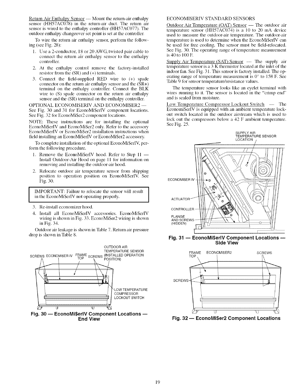
OPTIONAL ECONOMISERIV AND ECONOM[$ER2 --
See Fig. 30 and 31 for EconoMiSerIV component locations.
See Fig. 32 for EconoMiSer2 component locations.
NOTE: These instructions are for installing the optional
EconoMiSer[V and EconoMiSer2 only. Refer to the accessory
EconoMiSerIV or EconoMiSer2 installation instructions when
field inst_dling tin EconoMi$erIV or EconoMiSer2 accessory.
To complete inst_dlation of the optional EconoMiSerIV. per-
form the following procedure.
1. Remove the EconoMiSerIV hood. Refer to Step 11 --
Install Outdoor-Air Hood on page 11 for information on
removing and installing the outdoor-tfir hood.
2. Relocate outdoor air temperature sensor from shipping
position to operation position on EconoMiSerIV. See
Fig. 30.
I IMPORTANT: Failure to relocate the sensor will result
in the EconoMi$erlV not operating properly.
3. Re-inst_dl economizer hood.
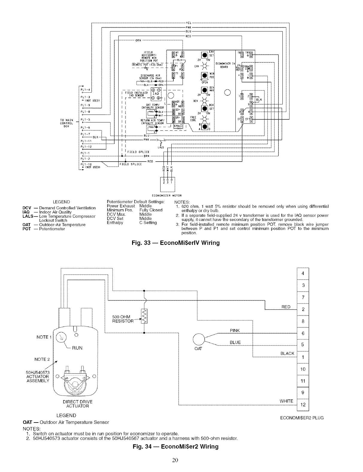
4. Install all EconoMiSerIV accessories. EconoMiSerIV
wiring is shown in Fig. 33. EconoMiSer2 wiring is shown
in Fig. 34.
Outdoor air leakage is shown in Table 7. Return air pressure
drop is shown in Table 8.
OUTDOOR AIR
TEMPERATURE SENSOR
SCREWS ECONOMI$ER IV FRAME SCREWS (INSTALLED OPERATION
/\ / _u_" \ POSITION)
Fig. 30 -- EconoMi$erlV Component Locations --
End View
ECONOMISERIV STANDARD SENSORS
Outdoor Air Temperature (OAT) Sensor -- The outdoor air
temperature sensor (HH57AC074) is a 10 to 20 mA device
used to measure the outdoor-air temperature. The outdoor-air
temperature is used to determine when the EconoMiSerIV can
be used for free cooling. The sensor must be field-relocated.
See Fig. 30. The operating range of temperature measurement
is 40 to 100 E
Supply Air Temperature (SAT) Sensor -- The supply air
temperature sensor is a 3 K thermistor located at the inlet of the
indoor fan. See Fig. 31. This sensor is factory installed. The op-
erating range of temperature measurement is 0 ° to 158 E See
Table 9 for sensor temperature/resistance values.
The temperature sensor looks like an eyelet terminal with
wires running to it. The sensor is located in the "crimp end"
and is sealed from moisture.
Low Temperature Compressor Lockout Switch -- The
EconomiSerIV is equipped with an ambient temperature lock-
out switch located in the outdoor airstream which is used to
lock out the compressors below a 42 F ambient temperature.
See Fig. 25.
SUPPLY AIR
TEMPERATURE SENSOR
LOCATION
ECONOMI$ER IV
FLANGE
(HIDDEN)
F
Fig. 31 -- EconoMi$erlV Component Locations --
Side View
FRAME ECONOMISER2 SCREWS
TOP \
SCREWS _'_tt '
Fig. 32- EconoMi$er2 Component Locations
19
USEOI
PLI =8
TO MAIN PLI_5
CONTROL
80X PL1-6
PLI_ll
PL1 -I
PL1-2
pck1-10
_" (NOl USED)
LEGEND
DCV -- Demand Controlled Ventilation
IAQ -- Indoor Air Quality
LALS-- Low Temperature Compressor
Lockout Switch
OAT -- Outdoor-Air Temperature
POT -- Potentiometer
YEL
'PNK
-BLU
REO
-- ORN
ACCESSORY) __ SET
REWOTEWIN
POS(T(ON POT BLK EV 10V
DISC.ARGEAIR _ [] Ml_
SENSOR (3k Ohm) POS
B LK--w,_4_0 -
[AOSENSOR I_. _l ( )iZv 10v
1 1 OA TTEMPI L -- _l I_ .fill /\DE V
I I E.TNAL_SE.SOR_ _'_ _ SET
l_lSO+_
I BLU-- SO EV lOv
RETURN AIR TEMPI COOL
I [NTHALPY SENSOR _ ._r
t t BLU
t _ PNK --3_
I I LAL$ ._
( I FIELD SPLICE
& _ BRN
RED
FIELD SPLICE
ECONONI ZER MOTOR
Potentiometer Default Settings: NOTES:
Power Exhaust Middle
Minimum Pos. Fully Closed
DCV Max. Middle
DCV Set Middle
Enthalpy C Setting
EEONOM($ER (v
ErI
/
1. 620 ohm, 1 watt 5% resistor should be removed only when using differential
enthalpy or dry bulb.
2. If a separate field-supplied 24 v transformer is used for the IAQ sensor power
supply, it cannot have the secondary of the transformer grounded.
3. Fer field-installed remote minimum position POT, remove black wire jumper
between P and P1 and set control minimum position POT to the minimum
position.
Fig. 33 -- EconoMi$erlV Wiring
/
NOTE 1
NOTE2
J
50HJ540573
ACTUATOR
ASSEMBLY
DIRECT DRIVE
ACTUATOR
LEGEND
OAT -- Outdoor Air Temperature Sensor
NOTES:
500 OHM
RESISTOR- _?
OAT
PINK
BLUE
4
3
7
RED 2
8
6
5
BLACK 1
10
11
9
WHITE 12
ECONOMI$ER2 PLUG
1. Switch on actuator must be in run position for economizer to operate.
2. 50HJ540573 actuator consists of the 50HJ540567 actuator and a harness with 500-ohm resistor.
Fig. 34 -- EconoMi$er2 Wiring
20
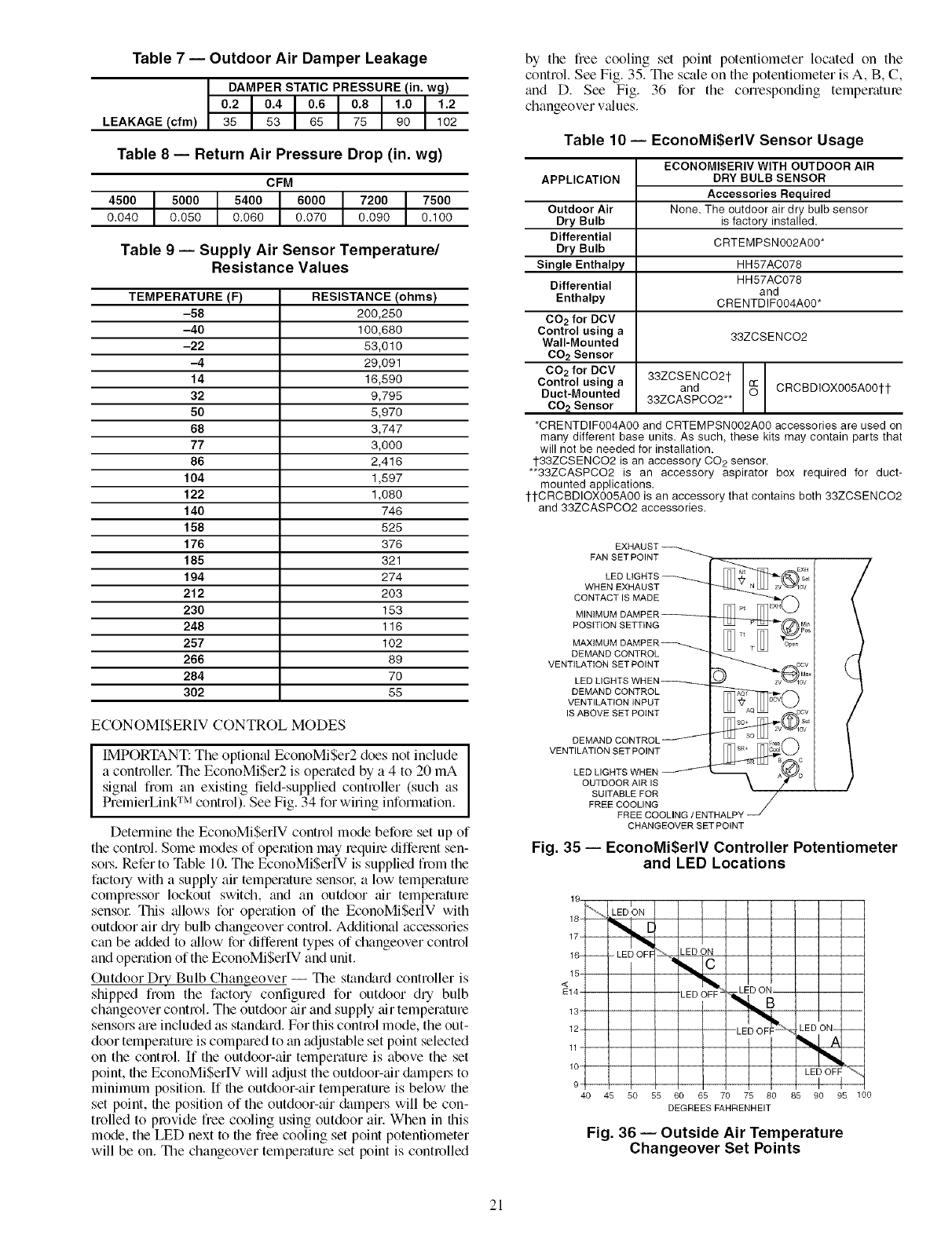
Table 7 -- Outdoor Air Damper Leakage
DAMPER STATIC PRESSURE (in. wg)
0.2 0.4 0.6 0.8 1.0 1.2
LEAKAGE(cfm) 35 53 65 75 90 102
Table 8 -- Return Air Pressure Drop (in. wg)
CFM
4500 5000 5400 6000 7200 7500
0.040 0.050 0.060 0.070 0.090 0.100
Table 9 -- Supply Air Sensor Temperature/
Resistance Values
TEMPERATURE (F) RESISTANCE (ohms)
-58 200,250
-40 100,680
-22 53,010
-4 29,091
14 16,590
32 9,795
50 5,970
68 3,747
77 3,000
86 2,416
104 1,597
122 1,080
140 746
158 525
176 376
185 321
194 274
212 203
230 153
248 116
257 102
266 89
284 70
302 55
ECONOMI$ERIV CONTROL MODES
IMPORTANT: Tile optional EconoMiSer2 does not include
a controllec The EconoMiSer2 is operated by a 4 to 20 mA
sign_fl from an existing field-supplied controller (such as
PremierLink TM control). See Fig. 34 for wMng information.
Detennine the EconoMiSerlV control mode befole set up of
the control. Some modes of operation may lequile diffelent sen-
sol:s. Refer to _Pable 10. Tile EconoMiSerIV is supplied from the
factory with a supply air temperature sensok a low tempemtme
compressor lockout switch, and an outdoor air tempemtme
sensoc This ;dlows for operation of the EconoMiSerIV with
outdoor air Ny bulb changeover control. Additional accessories
can be added to allow for diffelent types of changeover control
and operation of the EconoMi$erIV and unit.
Outdoor Dry Bulb Changeover -- The stan&trd controller is
shipped from the factory configmed for outdoor dry bulb
changeover control. The outdoor air and supply air temperature
sensors are included as stan&trd. For this control mode, the out-
door temperature is compmed to an adjustable set point selected
on the control If the outdoor-air temperature is above the set
point, the EconoMiSerIV will adjust the outdoor-air &tmpel:s to
minimum position. If file outdoor-air temperature is below the
set point, file position of the outdoor-air &tmpers will be con-
trolled to provide free cooling using outdoor air. When in this
mode, the LED next to the free cooling set point potentiometer
will be on. The changeover temperature set point is controlled
by the free cooling set point potentiometer located on the
control. See Fig. 35. The scale on the potentiometer is A, B, C,
and D. See Fig. 36 for the corresponding temperatme
changeover values.
Table 10 -- EconoMi$erlV Sensor Usage
APPLICATION
Outdoor Air
Dry Bulb
Differential
Dry Bulb
Single Enthalpy
Differential
Enthalpy
CO2 for DCV
Control using a
Wall-Mounted
CO2 Sensor
CO2 for DCV
Control using a
Duct-Mounted
CO2 Sensor
ECONOMISERIV WITH OUTDOOR AIR
DRY BULB SENSOR
Accessories Required
None. The outdoor air dry bulb sensor
is factory installed.
CRTEMPSN002A00*
HH57AC078
HH57AC078
and
CRENTDIF004A00*
33ZCSENCO2
33ZCSENCO21-
and CRCBDiOX005A001-1-
33ZCASPCO2**
*CRENTDIF004A00 and CRTEMPSN002A00 accessories are used on
many different base units. As such, these kits may contain parts that
will not be needed for installation.
1-33ZCSENCO2 is an accessory CO2 sensor.
**33ZCASPCO2 is an accessory aspirator box required for duct-
mounted applications.
1-1-CRCBDIOX005A00 is an accessory that contains both 33ZCSENCO2
and 33ZCASPCO2 accessories.
FAN SET POINT
LED
WHEN EXHAUST
CONTACT IS MADE
MINIMt
POSITION SETTING
MAXtMI
DEMAND CONTROL
VENTILATION SET POINT
LED kl(
DEMAND CONTROL
VENTILATION INPUT
IS ABOVE SET POINT
VENTILATION SET POINT
LED LIGHTS WHEN
OUTDOOR AIR IS
SUITABLE FOR
FREE COOLING
FREE COOLING /ENTHALP_'
CHANGEOVER SET POINT
Fig. 35 -- EconoMi$erlV Controller Potentiometer
and LED Locations
19 I
18 "%_, LEDON
,7
16= -- - LED OFF LED ON
_14 LED OFF
13 I
12
11
10
9
40 45 50 55 60 65 70 75 80
DEGREES FAHRENHEIT
-LED OFF L_ LED ON-- --
85 90 95 1 O0
Fig. 36 -- Outside Air Temperature
Changeover Set Points
21
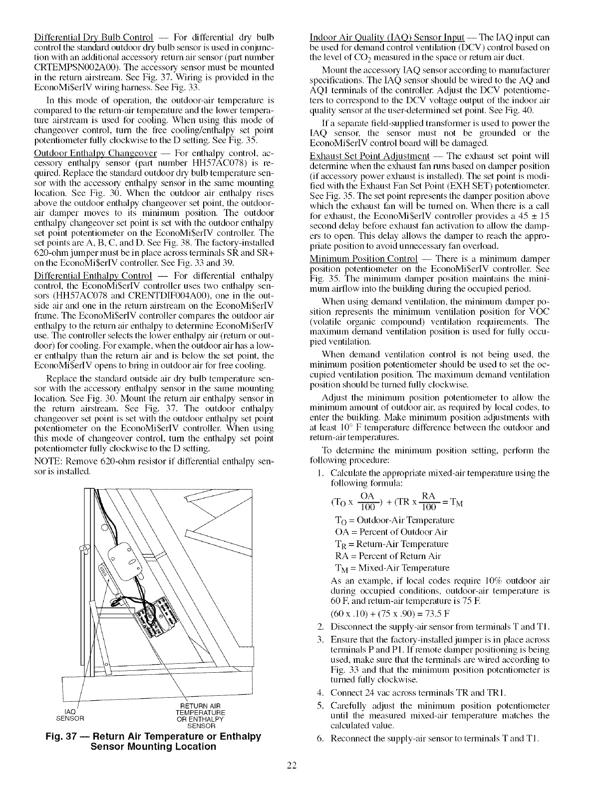
Differential Dry Bulb Control -- For differential dry bulb
control the standard outdoor dUbulb sensor is used in conjunc-
tion with an additional accessory return air sensor (part number
CRTEMPSN002A00). The accessory sensor must be mounted
in the return tfil.stream. See Fig. 37. Wiring is provided in the
EconoMiSer[V wiring harness. See Fig. 33.
In this mode of operation, file outdoor-air temperature is
compared to the return-tfir temperature and the lower tempera-
ture airstream is used for cooling. When using this mode of
changeover control, turn the free cooling/enthalpy set point
potentiometer fi.flly clockwise to the D setting. See Fig. 35.
Outdoor Enthalpy Changeover -- For enthalpy control, ac-
cessory enthalpy sensor (part number HH57AC078) is be-
quiredi Replace the standiu'd outdoor dry bulb temperature sen-
sor with the accesso Uenthalpy sensor in the same mounting
location. See Fig. 30. When the outdoor air enthalpy rises
above the outdoor enthalpy changeover set point, the outdoor-
air damper moves to its minimum position. Tile outdoor
enthalpy changeover set point is set with the outdoor enthalpy
set point potentiometer on the EconoMiSerIV controllel: The
set points are A, B, C, and D. See Fig. 38. The factory-installed
620-ohm jumper must be in place across terminals SR and SR+
on the EconoMi$erIV controllel: See Fig. 33 and 39.
Differential Enthalpy Control -- For differential enthalpy
control, the EconoMi$erIV controller uses two enthalpy sen-
sors (HH57AC078 and CRENTDIF004A00), one in the out-
side tfir and one in the return _fil.stream on the EconoMiSerIV
frmne. The EconoMi$erlV controller compares the outdoor _fir
enthalpy to the leturn tfir enthalpy to determine EconoMiSer[V
use. The controller selects the lower enthalpy air (return or out-
door) for cooling. For example, when the outdoor air has a low-
er enthalpy than the return air and is below the set point, the
EconoMiSerIV opens to bring in outdoor air for free cooling.
Replace the standard outside air diy bulb temperature sen-
sor with the accesso Uenth_dpy sensor in the same mounting
location. See Fig. 30. Mount the return air enthalpy sensor in
the return airstream. See Fig. 37. The outdoor enthalpy
changeover set point is set with the outdoor enthalpy set point
potentiometer on the EconoMi$erIV controllec When using
this mode of changeover control, turn the enth_dpy set point
potentiometer fiJlly clockwise to the D setting.
NOTE: Remove 620-ohm resistor if differential enthalpy sen-
sor is installed.
RETURN AIR
IAQ TEMPERATURE
SENSOR OR ENTHALPY
SENSOR
Fig. 37 -- Return Air Temperature or Enthalpy
Sensor Mounting Location
Indoor Air Quality dAQ) Sensor Input -- The IAQ input can
be used for demand control ventikttion (DCV) control based on
the level of CO 2measured in the space or return air duct.
Mount the accessory IAQ sensor according to manufacturer
specifications. The IAQ sensor should be wired to the AQ and
AQI terminals of the controller Adjust the DCV potentiome-
ters to correspond to file DCV voltage output of the indoor air
quCdity sensor at the user-determined set point. See Fig. 40.
If a separate field-supplied transformer is used to power the
IAQ sensor, the sensor must not be grounded or the
EconoMiSerIV control board will be damaged.
Exhaust Set Point Adjustment -- The exhaust set point will
determine when the exhaust fan runs based on damper position
(if accessory power exhaust is installed). The set point is modi-
fied with the Exhaust Fan Set Point (EXH SET) potentiometer.
See Fig. 35. The set point represents the dmnper position above
which the exhaust fan will be turned on. When there is a call
for exhaust, the EconoMiSerIV controller provides a 45 _+15
second delay before exhaust fan activation to allow the damp-
ers to open. This delay allows the damper to reach the appro-
priate position to avoid unnecessary fan overload.
Minimum Position Control -- There is a minimum damper
position potentiometer on the EconoMiSerlV controllel: See
Fig. 35. The minimum dmnper position maintains file mini-
mum airflow into the building during the occupied period.
When using demand ventilation, the minimum damper po-
sition lepresents the minimum ventilation position for VOC
(volatile organic compound) ventilation requirements. The
maximum demand ventilation position is used for fully occu-
pied ventilation.
When demand ventilation control is not being used, the
minimum position potentiometer should be used to set the oc-
cupied ventilation position. The maximum demand ventilation
position should be turned fully clockwise.
Adjust the minimum position potentiometer to _dlow the
minimum amount of outdoor air. as required by local codes, to
enter the building. Make minimum position adjustments with
at least 10° F temperature difference between the outdoor and
return-air temperatures.
To determine the minimum position setting, perform the
following procedure:
1. Calculate the appropriate mixed-air temperature using the
following formula:
OA RA
(To x l---ff_ ) + (TR x _ = TM
To = Outdoor-Air Temperature
OA = Percent of Outdoor Air
T R = Return-Air Temperature
RA = Percent of Return Air
TM = Mixed-Air Temperature
As an example, if local codes require 10% outdoor air
during occupied conditions, outdoor-tilt temperature is
60 E and return-air temperature is 75 E
(60 x. 10) + (75 x .90) = 73.5 F
2. Disconnect the supply-air sensor from terminals T and TI.
3. Ensure that the factory-installed jumper is in place across
terminals P and PI. If lemote damper positioning is being
used, make sure that the termimds are wired according to
Fig. 33 and that the minimum position potentiometer is
turned fully clockwise.
4. Connect 24 vac across termimds TR and TRI.
5. Cmefully adjust the minimum position potentiometer
until file measured mixed-tilt temperatme matches the
calculated v_due.
6. Reconnect the supply-air sensor to terminals T and TI.
22
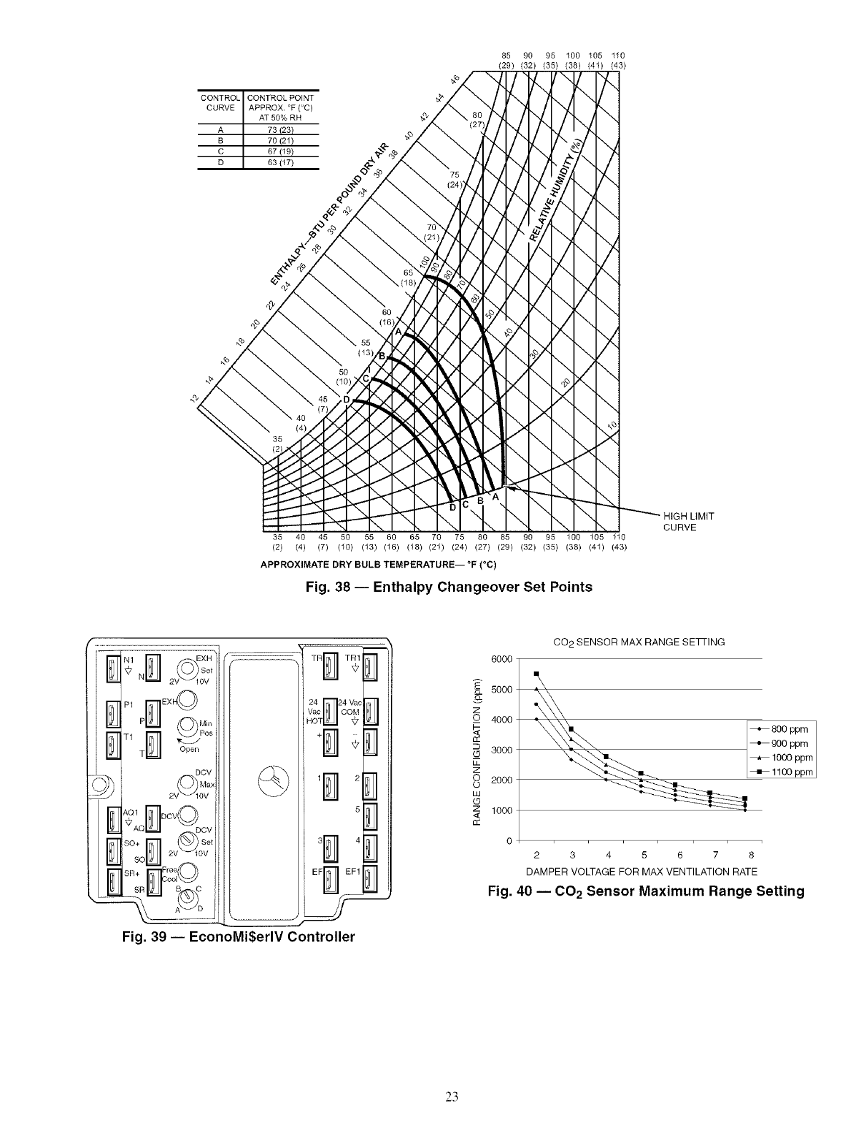
CONTROL CONTROL POINT
CURVE APPROX. °F (°C)
AT 50% RH
A 73 (23)
B 70/21)
C 67/19)
D 63 (17)
85 90 95 100 105 110
(29) (32) (35) (38) (41) (43)
\
\
>I
_HIGH LIMIT
CURVE
35 40 45 50 55 60 65 70 75 80 85 90 95 100 105 1t0
(2) (4) (7) (10) (13) (16) (18) (21) (24) (27) (29) (32) (35) (38) (41) (43)
APPROXIMATE DRY BULB TEMPERATURE-- °F (°C)
Fig. 38 -- Enthalpy Changeover Set Points
I_HI_ ItHI (O_so,
I_ N_l_JI 2V_10V
I_-]1 P1 r_ EXh_
_1_-,_ T_l_--J Open
\Q1 DCV
M*AOnO v
2V --10V
W sou
SR+ Free
n oo,O
SR_I__J B C
L?IU_
-- "-_\ A_LLT/o
L
TRr'_'-_ T_
24 824 Vac
Vac COM
HOT '_7
.......
_ 2
5
......._ 4
EF_ EF1
Fig. 39 -- EconoMi$erlV Controller
m
6OOO
5000
z4000
3000
z
©2000
O
w
z 1000
CO 2 SENSOR MAX RANGE SEqq-ING
+800 ppm
+900 ppm
_1000 ppm
_1100 ppm
2345 678
DAMPER VOLTAGE FOR MAX VENTILATION RATE
Fig. 40 -- 002 Sensor Maximum Range Setting
23
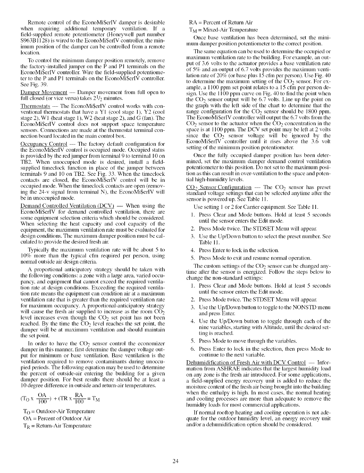
RemotecontroloftheEconoMi$erWdamperisdesirable
whenrequitingadditiomdtempor_wyventilation.If a
field-suppliedlemotepotentiometer(Honeywellpartnumber
$963B1128)iswiredtotheEconoMi$erIVcontrollel_themin-
imumpositionofthedampercanbecontrolledfromaremote
location.
Tocontroltheminimumdamperpositionlemotely,remove
thefactory-installedjumperonthePandPl terminalsonthe
EconoMi$erlVcontrollecWirethefield-suppliedpotentiome-
tertothePandPl terminalsontheEconoMi$erlVcontrollec
SeeFig.39.
DamperMovement-- Dampermovementfiomfullopento
fullclosed(orvicevelsa)t:_es21/2minutes.
Thermostats -- The EconoMi$erIV control works with con-
ventional thermostats that have a YI (cool stage 1), Y2 (cool
stage 2), WI (heat stage 1), W2 (heat stage 2), and G (fan). The
EconoMi$erIV control does not support space temperature
sensors. Connections are made at the thermostat terminal con-
nection board located in the main control box.
Occupancy Control -- The factory default configuration for
the EconoMi$erIV control is occupied mode. Occupied status
is provided by the red jumper from terminal 9 to terminal 10 on
TB2. When unoccupied mode is desired, install a field-
supplied timeclock function in place of the jumper between
terminals 9 and 10 on TB2. See Fig. 33. When the timeclock
contacts ;u'e closed, the EconoMi$erlV control will be in
occupied mode. When the timeclock contacts are open (remov-
ing the 24-v signal fi:om termimfl N), the EconoMi$erIV will
be in unoccupied mode.
Demand Controlled Ventilation (DCV) -- When using the
EconoMi$erIV for demand controlled ventilation, there tue
some equipment selection criteria which should be considered.
When selecting the heat capacity and cool capacity of the
equipment, the maximum ventilation rate must be evaluated for
design conditions. The maximum dmnper position must be cal-
culated to provide the desired fiesh till:
Typically the maximum ventilation rate will be about 5 to
10% more than the typical cfin required per peLson, using
normal outside air design criteria.
A proportional anticipatory strategy should be taken with
the following conditions: a zone with a large area, varied occu-
pancy, and equipment that cannot exceed the required ventila-
tion rate at design conditions. Exceeding the required ventila-
tion rate means the equipment can condition air at a maximum
ventilation rate that is greater than the lequired ventilation rate
for maximum occupancy. A proportional-anticipatory strategy
will cause the fresh air supplied to increase as the room CO2
level increases even though the CO 2 set point has not been
reached. By the time the CO 2 level reaches the set point, the
dmnper will be at maximum ventilation and should mtfint;fin
the set point.
In order to have the CO2 sensor control the economizer
dmnper in this manner, first determine the damper voltage out-
put for minimum or base ventilation. Base ventilation is the
ventilation required to remove contaminants during unoccu-
pied periods. The following equation may be used to determine
the percent of outside-tfir entering the building for a given
damper position. For best results thele should be at least a
10 degree difference in outside and _etum-air temperatures.
OA RA
(To x 1-i--0-0-) + (TR x 1-i--0-0-= TM
To = Outdoor-Air Temperature
OA = Percent of Outdoor Air
TR = Return-Air Temperatme
RA = Percent of Return Air
TM = Mixed-Air Temperature
Once base ventilation has been determined, set the mini-
mum damper position potentiometer to the correct position.
The same equation can be used to determine the occupied or
maximum ventilation rote to the building. For example, an out-
put of 3.6 volts to the actuator provides a base ventilation rate
of 5% and an output of 6.7 volts provides the maximum venti-
lation rate of 20% (or base plus 15 cfm per person). Use Fig. 40
to determine the maximum setting of the CO 2 sensor. For ex-
ample, a 1100 ppm set point relates to a 15 cfm per person de-
sign. Use the 1100 ppm curve on Fig. 40 to find the point when
the CO 2 sensor output will be 6.7 volts. Line up the point on
the graph with the left side of the chart to determine that the
range configuration for the CO 2 sensor should be 1800 ppm.
The EconoMiSerIV controller will output the 6.7 volts from the
CO 2 sensor to the actuator when the CO 2 concentration in the
space is at 1100 ppm. The DCV set point may be left at 2 volts
since the CO 2 sensor voltage will be ignored by the
EconoMiSerIV controller until it rises above the 3.6 volt
setting of the minimum position potentiometel:
Once the fully occupied dmnper position has been deter-
mined, set the maximum dalnper demand control ventilation
potentiometer to this position. Do not set to the maximum posi-
tion as this can result in over-ventilation to the space and poten-
tial high-humidity levels.
CO_2 Sensor Configuration -- The CO 2 sensor has preset
standard voltage settings that can be selected anytime after the
sensor is powered up. See Table 11.
Use setting 1 or 2 for Carrier equipment. See Table 11.
1. Press Clear and Mode buttons. Hold at least 5 seconds
until the sensor enters the Edit mode.
2. Press Mode twice. The STDSET Menu will appem:
3. Use the Up/Down button to select the preset numbel: See
Table 11.
4. Press Enter to lock in the selection.
5. Press Mode to exit and resume norm_d operation.
The custom settings of the CO2 sensor can be changed any-
time after the sensor is energized. Follow the steps below to
change file non-stan&rd settings:
1. Press Clear and Mode buttons. Hold at least 5 seconds
until the sensor enters the Edit mode.
2. Press Mode twice. The STDSET Menu will appeal:
3. Use the Up/Down button to toggle to the NONSTD menu
and press Entel:
4. Use the Up/Down button to toggle through each of the
nine variables, starting with Altitude, until file desired set-
ting is reached.
5. Press Mode to move through the variables.
6. Press Enter to lock in the selection, then press Mode to
continue to the next v;uiable.
Dehumidification of Fresh Air with DCV Control -- Infor-
mation from ASHRAE indicates that the largest humidity load
on any zone is the fresh air introduced. For some applications,
a field-supplied energy recovery unit is added to reduce the
moisture content of the flesh air being brought into the building
when the enthalpy is high. In most cases, the normal heating
and cooling processes are mole than adequate to remove the
humidity loads for most commercial applications.
If normal rooftop heating and cooling operation is not ade-
quate for the outdoor humidity level, an energy recovery unit
and/or a dehumidification option should be considered.
24
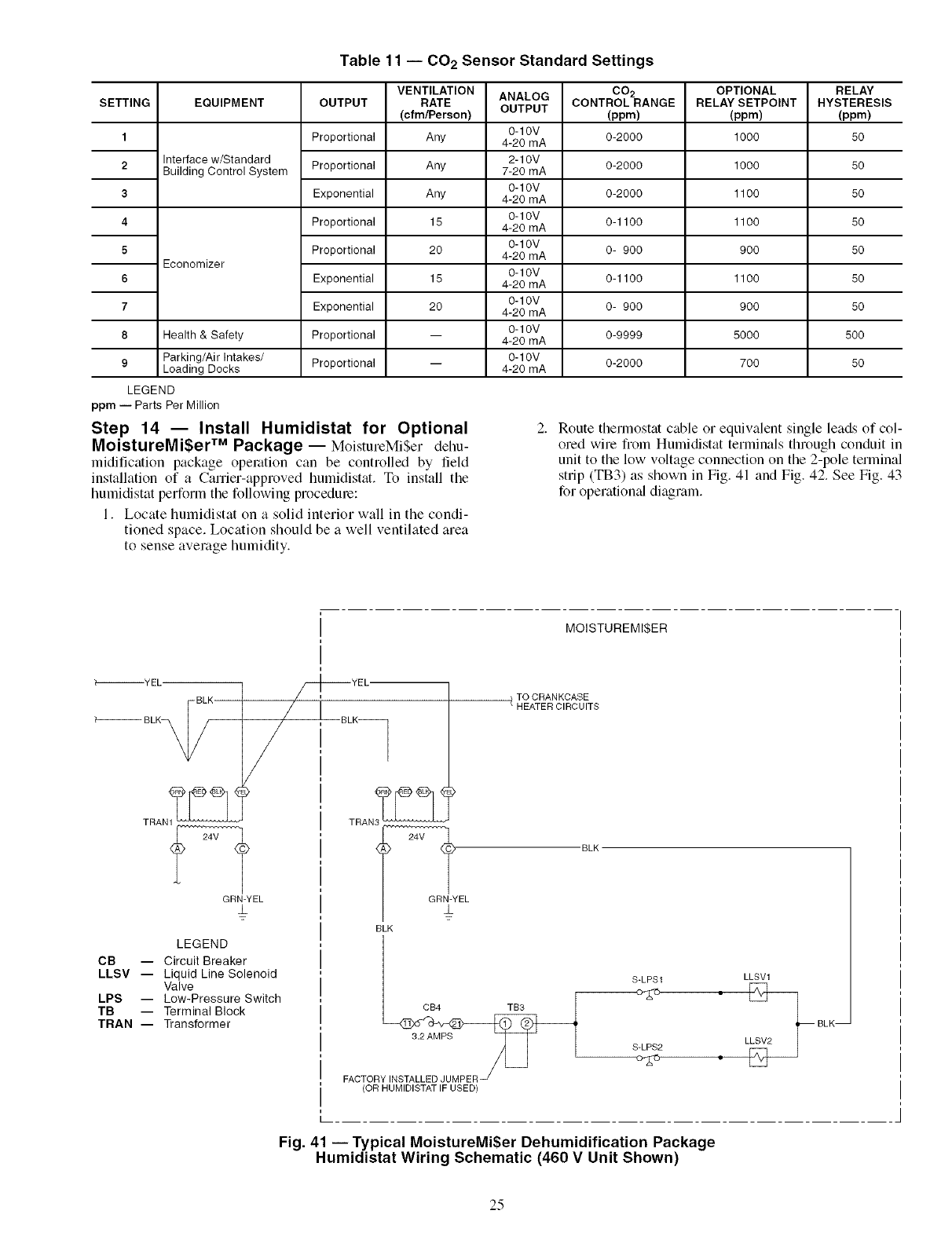
Table 11 -- CO 2Sensor Standard Settings
EQUIPMENTSETTING
1
2
3
4
5
6
7
8
9
Interface w/Standard
Building Control System
Economizer
Health & Safety
Parking/Air Intakes/
Loading Docks
OUTPUT
Proportional
Proportional
Exponential
Proportional
Proportional
Exponential
Exponential
Proportional
Proportional
VENTILATION
RATE
(cfm/Person)
Any
Any
Any
15
20
15
20
ANALOG
OUTPUT
0-10V
4-20 mA
2-10V
7-20 mA
0-10V
4-20 mA
0-10V
4-20 mA
0-10V
4-20 mA
0-10V
4-20 mA
0-10V
4-20 mA
0-10V
4-20 mA
0-10V
4-20 mA
CO2
CONTROLRANGE
(ppm)
0-2000
0-2000
0-2000
0-1100
0- 900
0-1100
0- 900
0-9999
0-2000
OPTIONAL
RELAY SETPOINT
(ppm)
1000
1000
1100
1100
900
1100
900
5000
7OO
LEGEND
ppm -- Parts Per Million
Step 14 -- Install Humidistat for Optional
MoistureMi$er TM Package -- MoistureMiSer dehu-
midification package operation can be controlled by fiield
installation of a Carrier-approved humidistat. To install tile
bumidistat perforln the following procedure:
1. Locate humidistat on a solid interior wall in the condi-
tioned space. Location should be a well ventilated area
to sense average humidity.
RELAY
HYSTERESIS
(ppm)
50
50
50
50
50
50
50
500
50
Route thermostat cable or equivalent single leads of col-
ored wire fiom Humidistat terrninals through conduit in
unit to the low voltage connection on the 2-pole terminal
strip (TB3) as shown in Fig. 41 and Fig. 42. See Fig. 43
for operational diagram.
MOISTUREMI$ER
_-_YEL
BLK
BLK_
TRAN1TM
GRN-YEL
±
/_r_YEL
/,
// !
LEGEND
CB -- Circuit Breaker
LLSV -- Liquid Line Solenoid
Valve
LPS -- Low-Pressure Switch
TB -- Terminal Block
TRAN- Transformer
TO CRANKCASE
/ HEATER CIRCUITS
TRAN3TM
4_E L "BLK
BLK
S-LPS1
CB4 TB3
3.2 AMPS S LPS2FACTOR
(OR HUMIDISTATIF USED)
LLSV1
** LLSV2_ BLK-
Fig. 41 -- Typical MoistureMi$er Dehumidification Package
Humidistat Wiring Schematic (460 V Unit Shown)
25
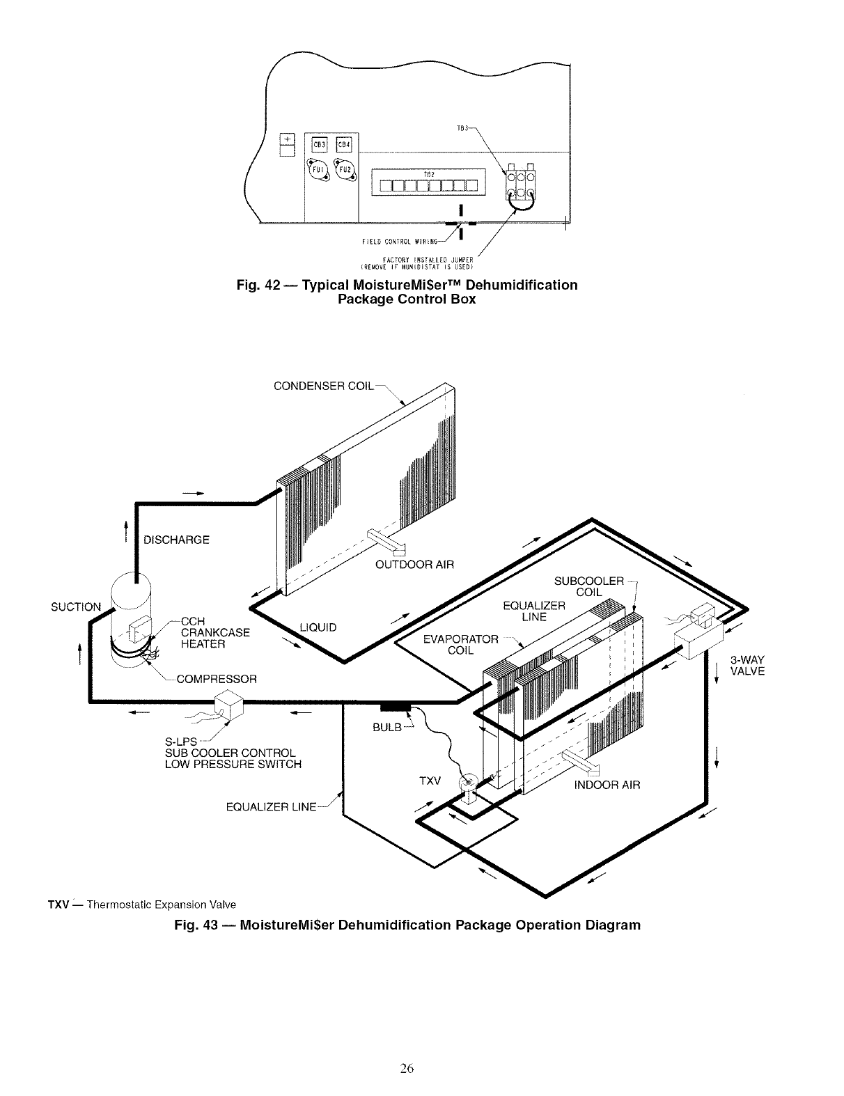
FIE_DCONTROLWIRER6J| --/
FACTORY INSTALLED JUMPED
IRE_OVE IF HDMIDISTA[ IS USED}
Fig. 42 -- Typical MoistureMi$er TM Dehumidification
Package Control Box
SUCTION
t
l DISCHARGE
CRANKCASE
HEATER
CONDENSER COIL_
LIQUID
OUTDOOR AIR
SUBCOOLERo 1
COIL /
EQUALIZER
LINE
EVAPORATOR \
COIL 3-WAY
I VALVE
S-LPS
SUB COOLER CONTROL
LOW PRESSURE SWITCH
EQUALIZER
BULB
TXV
TXV" Thermostatic Expansion Valve
Fig. 43 -- MoistureMi$er Dehumidification Package Operation Diagram
26
START-UP
Use the following infonnation and Start-Up Checklist on
page CL-I to check out unit PRIOR to start-up.
Unit Preparation -- Check that unit has been installed in
accordance with these installation instructions and all applica-
ble codes.
COMPRESSOR MOUNTING -- Compressors are internally
spring mounted. Do not loosen or remove compressor hold-
down bolts.
REFRIGERANT SERVICE PORTS -- Each lefiigerant sys-
tem has a total of 3 Schrader-type service gage ports. One port
is located on the suction line, one on the compressor discharge
line, and one on the liquid line. In addition Schmder-type
valves are located underneath file low-pressme switches. Be
sure that caps on the ports are tight.
COMPRESSOR ROTATION -- It is important to be certain
the compressors me rotating in the proper direction. To deter-
mine whether or not compressors are rotating in the proper
direction:
1. Connect service gages to suction and discharge pressure
fittings.
2. Energize the compressoc
3. The suction pressure should chop and the discharge pies-
sure should rise, as is normal on any start-up.
If the suction pressure does not drop and the discharge pies-
sure does not rise to normal levels:
1. Note that the evaporator fan is probably also rotating in
the wrong direction.
2. Tnrn off power to the unit.
3. Reverse any two of the incoming power leads.
4. Turn on power to the compressol:
The suction and discharge pressure levels should now move
to their normal start-up levels.
NOTE: When compressors are rotating in the wrong direction,
the unit will have incleased noise levels and will not provide
heating and cooling.
After a few minutes of reverse operation, the scroll com-
pressor internal overload protection will open, which will
activate the unit's lockout and requires a manual reset. Reset is
accomplished by turning the thermostat on and off.
INTERNAL WIRING- Check all electrical connections in
unit control boxes; tighten as required.
CRANKCASE HEATER(S)- Crankcase heater(s) is ener-
gized as long as there is power to the unit and the compressor is
not operating.
IMPORTANT: Unit power must be on for 24 hom_ prior to ]
start-up. Otherwise, &_mage to compressor may result. J
EVAPORATOR FAN- Fan belt and vmiable pulleys me
factoq-installed. Remove tape from the fan pulley. See
Tables 12-17 for fan performance data. Be sure that fans rotate
in the proper direction. See Table 18 for air quantity limits. See
Table 19 for evaporator fan motor specifications. See Tables 20
and 21 for static pressure information for accessories and
options. See Table 22 for fan rpm at various motor pulley
settings. To alter fan performance, see Evaporator Fan Perfor-
mance Adjustment section on page 38.
NOTE: A 31/2-in. bolt and threaded plate are included in the
installer's packet. They can be added to the motor support
channel below the motor mounting plate to aid in raising the
fan motolt
CONDENSER-FANS AND MOTORS-- Condenser fans
and motors gu'efactol T set. Refer to Condenser-Fan Adjustment
section (page 40) as required. Be sure that fans rotate in the
proper direction.
RETURN-AIR FILTERS -- Check that correct filters are in-
stalled in filter tracks (see Table 1). Do not operate unit without
return-air filte_.s.
OUTDOOR-AIR INLET SCREENS -- Outdoor-air inlet
screens must be in place before operating unit.
GAS HEAT -- Verify gas plessures before turning on heat as
follows:
1. Turn off manual gas stop.
2. Connect pressure gage to supply gas pressure tap (see
Fig. 12).
3. Connect pressure gage to manifold pressure tap on gas
valve.
4. Turn on manual gas stop and set thermostat to HEAT
position. After the unit has run for several minutes, verify
that incoming pressure is 5.5 in. wg or greater, and that
the manifold pressure is 3.3 in. wg. If manifold pressure
must be adjusted, refer to Gas Vtdve Adjustment section
on page 40.
5. After unit has been in operation for 5 minutes, check tem-
perature rise across the heat exchangel.s. See unit infor-
mative plate for correct rise limits of the heat supplied.
Air quantities may need to be adjusted to bring the actual
rise to within the allowable limits.
27
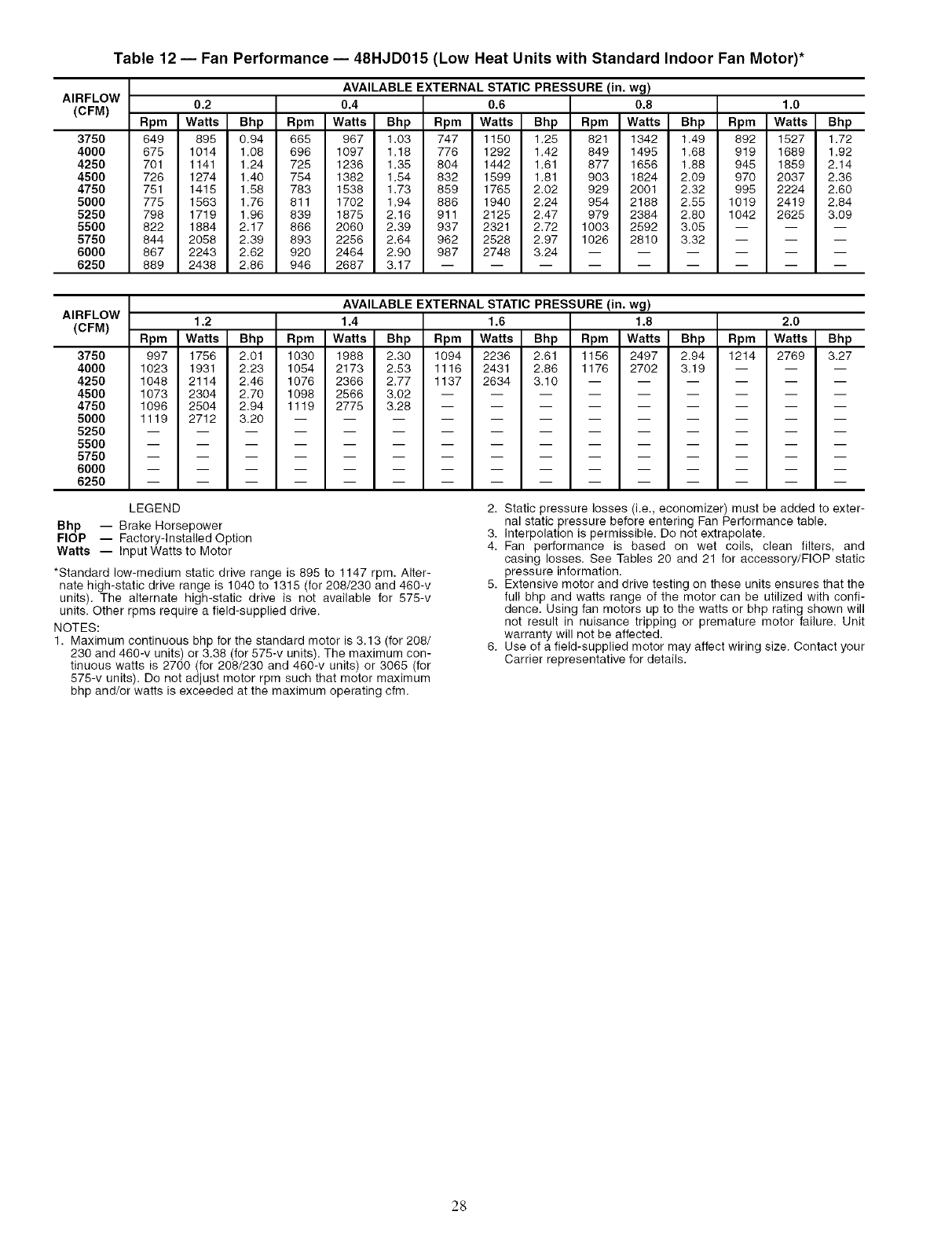
Table 12 -- Fan Performance -- 48HJD015 (Low Heat Units with Standard Indoor Fan Motor)*
AIRFLOW
(CFM)
3750
4000
4250
4500
4750
5000
5250
5500
5750
6000
6250
AVAILABLE EXTERNAL STATIC PRESSURE (in. wg)
0.2 0.4 0.6 0.8 1.0
Rpm Watts Bhp Rpm Watts Bhp Rpm Watts Bhp Rpm Watts Bhp Rpm Watts Bhp
649 895 0.94 665 967 1.03 747 1150 1.25 821 1342 1.49 892 1527 1.72
675 1014 1.08 696 1097 1.18 776 1292 1.42 849 1495 1.68 919 1689 1.92
701 1141 1.24 725 1236 1.35 804 1442 1.61 877 1656 1.88 945 1859 2.14
726 1274 1.40 754 1382 1.54 832 1599 1.81 903 1824 2.09 970 2037 2.36
751 1415 1.58 783 1538 1.73 859 1765 2.02 929 2001 2.32 995 2224 2.60
775 1563 1.76 811 1702 1.94 886 1940 2.24 954 2188 2.55 1019 2419 2.84
798 1719 1.96 839 1875 2.16 911 2125 2.47 979 2384 2.80 1042 2625 3.09
822 1884 2,17 866 2060 2,39 937 2321 2,72 1003 2592 3,05 -- -- --
844 2058 2,39 893 2256 2,64 962 2528 2,97 1026 2810 3.32 -- -- --
867 2243 2,62 920 2464 2,90 987 2748 3.24 ......
889 2438 2,86 946 2687 3.17 .........
AIRFLOW
(CFM)
3750
4000
4250
4500
4750
5000
5250
5500
5750
6000
6250
AVAILABLE EXTERNAL STATIC PRESSURE (in. wg)
1.2 1.4 1.6 1.8 2.0
Rpm Watts Bhp Rpm Watts Bhp Rpm Watts Bhp Rpm Watts Bhp Rpm Watts Bhp
997 1756 2.01 1030 1988 2.30 1094 2236 2.61 1156 2497 2.94 1214 2769 3.27
1023 1931 2.23 1054 2173 2.53 1116 2431 2.86 1176 2702 3.19 -- -- --
1048 2114 2.46 1076 2366 2.77 1137 2634 3.10 ......
1073 2304 2.70 1098 2566 3.02 .........
1096 2504 2.94 1119 2775 3.28 .........
1119 2712 3.20 ............
LEGEND
Bhp -- Brake Horsepower
FlOP -- Factory-Installed Option
Watts -- Input Watts to Motor
*Standard low-medium static drive range is 895 to 1147 rpm. Alter-
nate high-static drive range is 1040 to 1315 (for 208/230 and 460-v
units). The alternate high-static drive is not available for 575-v
units. Other rpms require a field-supplied drive.
NOTES:
1. Maximum continuous bhp for the standard motor is 3.13 (for 208/
230 and 460-v units) or 3.38 (for 575-v units), The maximum con-
tinuous watts is 2700 (for 208/230 and 460-v units) or 3065 (for
575-v units). Do net adjust motor rpm such that motor maximum
bhp and/or watts is exceeded at the maximum operating cfm.
2. Static pressure losses (i.e., economizer) must be added to exter-
nal static pressure before entering Fan Performance table.
3. Interpolation is permissible. Do not extrapolate.
4. Fan performance is based on wet coils, clean filters, and
casing losses. See Tables 20 and 21 for accessory/FlOP static
pressure information.
5. Extensive motor and drive testing on these units ensures that the
full bhp and watts range of the motor can be utilized with confi-
dence. Using fan motors up to the watts or bhp rating shown will
not result in nuisance tripping or premature motor failure. Unit
warranty will not be affected.
6. Use of a field-supplied motor may affect wiring size. Contact your
Carrier representative for details.
28
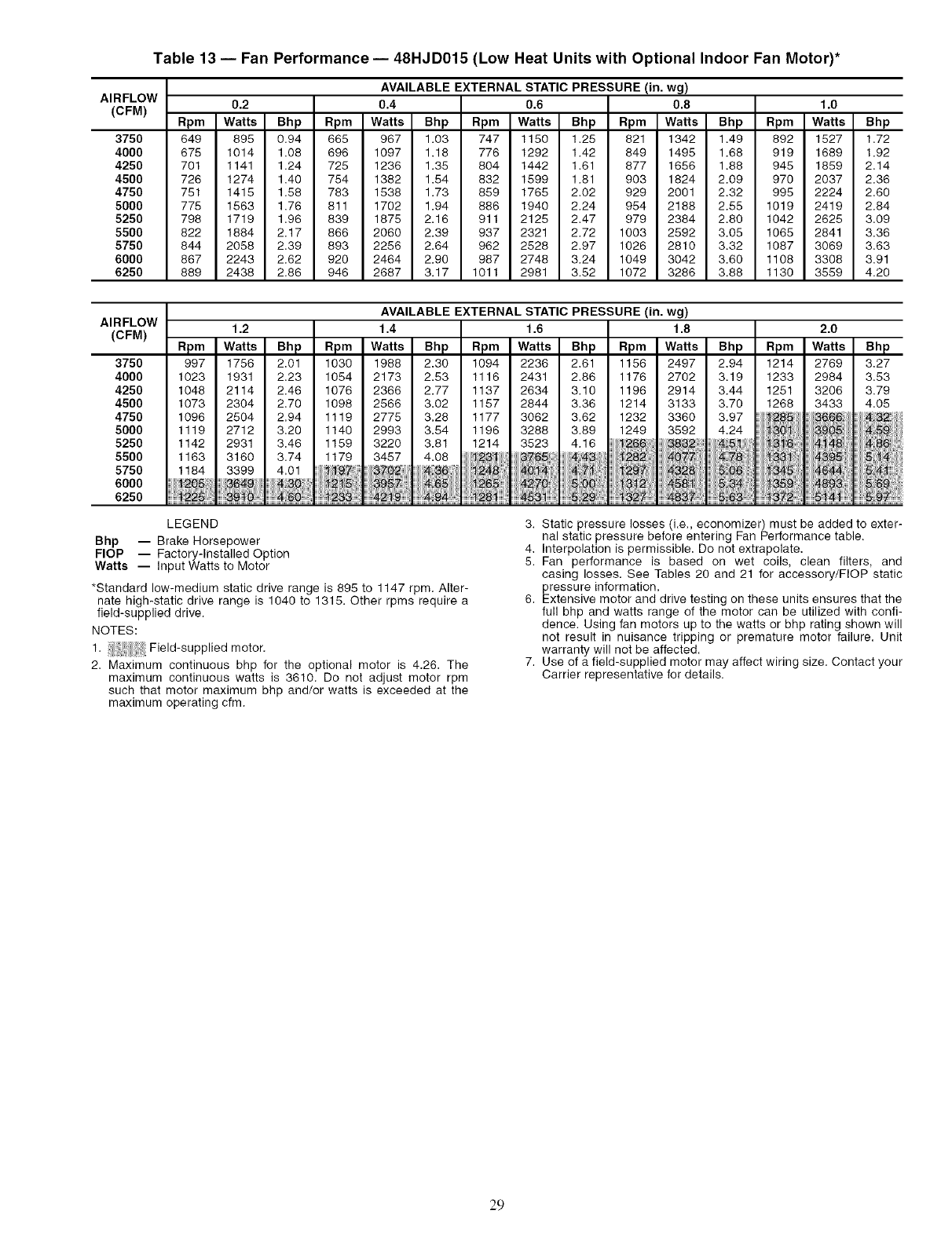
Table 13 -- Fan Performance -- 48HJD015 (Low Heat Units with Optional Indoor Fan Motor)*
AIRFLOW
(CFM)
375O
4000
4250
4500
4750
5000
5250
5500
5750
6000
6250
AVAILABLE EXTERNAL STATIC PRESSURE (in. wg)
0.2 0.4 0.6 0.8 1.0
Rpm Watts Bhp Rpm Watts Bhp Rpm Watts Bhp Rpm Watts Bhp Rpm Watts Bhp
649 895 0.94 665 967 1.03 747 1150 1.25 821 1342 1.49 892 1527 1.72
675 1014 1.08 696 1097 1.18 776 1292 1.42 849 1495 1.68 919 1689 1.92
701 1141 1.24 725 1236 1.35 804 1442 1.61 877 1656 1.88 945 1859 2.14
726 1274 1.40 754 1382 1.54 832 1599 1.81 903 1824 2.09 970 2037 2.36
751 1415 1.58 783 1538 1.73 859 1765 2.02 929 2001 2.32 995 2224 2.60
775 1563 1.76 811 1702 1.94 886 1940 2.24 954 2188 2.55 1019 2419 2.84
798 1719 1.96 839 1875 2.16 911 2125 2.47 979 2384 2.80 1042 2625 3.09
822 1884 2.17 866 2060 2.39 937 2321 2.72 1003 2592 3.05 1065 2841 3.36
844 2058 2.39 893 2256 2.64 962 2528 2.97 1026 2810 3.32 1087 3069 3.63
867 2243 2.62 920 2464 2.90 987 2748 3.24 1049 3042 3.60 1108 3308 3.91
889 2438 2.86 946 2687 3.17 1011 2981 3.52 1072 3286 3.88 1130 3559 4.20
AVAILABLE EXTERNAL STATIC PRESSURE (in. wg)
AIRFLOW 1.2 1.4 1.6 1.8 2.0
(CFM) Rpm Watts Bhp Rpm Watts Bhp Rpm Watts Bhp Watts Bhp Watts Bhp
3750 997 1756 2.01 1030 1988 2.30 1094 2236 2.61 2497 2.94 2769 3.27
4000 1023 1931 2.23 1054 2173 2.53 1116 2431 2.86 2702 3.19 2984 3.53
4250 1048 2114 2.46 1076 2386 2.77 1137 2634 3.10 2914 3.44 3206 3.79
4500 1073 2304 2.70 1098 2566 3.02 1157 2844 3.36 3133 3.70 3433 4.05
4750 1096 2504 2.94 1119 2775 3.28 1177 3062 3.62 3360 3.97 3666 47_
5000 1119 2712 3.20 1140 2993 3.54 1196 3288 3.89 3592 4.24
5250 1142 2931 3.46 1159 3220 3.81 1214 3523 4.16 _32 4;5_ '
5500 1163 3160 3.74 1179 3457 4.08 23 _76_ j4_ 40 _478 39
5750 1184 3399 4.01 4._6 _ _.? _ _2 06 5
6000 65 26 _ ;5 56:1:5 _
6250 22 : _:94:28 #_7 ;;;563:
LEGEND
Bhp -- Brake Horsepower
FlOP -- Factory-Installed Option
Watts -- Input Watts to Motor
*Standard low-medium static drive range is 895 to 1147 rpm. Alter-
nate high-static drive range is 1040 to 1315. Other rpms require a
field-supplied drive.
NOTES:
1. i i Field-supplied motor.
2. Maximum continuous bhp for the optional motor is 4.26. The
maximum continuous watts is 3610, Do not adjust motor rpm
such that motor maximum bhp and/or watts is exceeded at the
maximum operating cfm.
3. Static pressure losses (i.e., economizer) must be added to exter-
nal static pressure before entering Fan Performance table.
4. Interpolation is permissible. Do not extrapolate.
5. Fan performance is based on wet coils, clean filters, and
casing losses. See Tables 20 and 21 for accessory/FlOP static
pressure information.
6. Extensive motor and drive testing on these units ensures that the
full bhp and watts range of the motor can be utilized with confi-
dence. Using fan motors up to the watts or bhp rating shown will
not result in nuisance tripping or premature motor failure. Unit
warranty will not be affected.
7. Use of a field-supplied motor may affect wiring size. Contact your
Carrier representative for details.
29
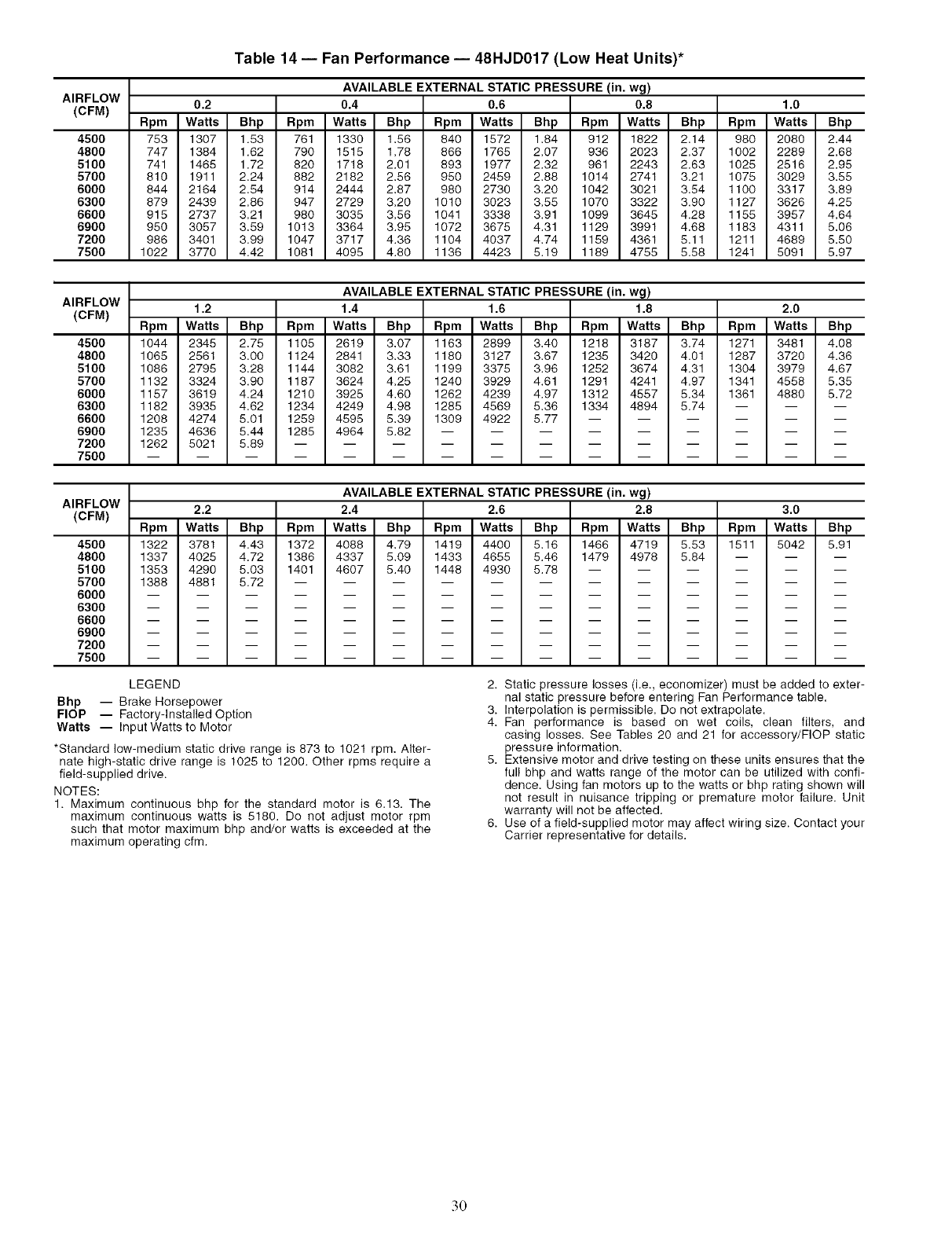
AIRFLOW
(CFM)
4500
4800
5100
5700
6000
6300
6600
6900
7200
7500
Table 14 -- Fan Performance -- 48HJD017 (Low Heat Units)*
AVAILABLE EXTERNAL STATIC PRESSURE (in. wg)
0.2 0.4 0.6 0.8 1.0
Rpm Watts Bhp Rpm Watts Bhp Rpm Watts Bhp Rpm Watts Bhp Rpm Watts Bhp
753 1307 1.53 761 1330 1,86 840 1572 1,84 912 1822 2,14 980 2080 2,44
747 1384 1.62 790 1515 1.78 866 1765 2.07 936 2023 2.37 1002 2289 2.68
741 1465 1.72 820 1718 2.01 893 1977 2.32 961 2243 2.63 1025 2516 2.95
810 1911 2.24 882 2182 2.56 950 2459 2.88 1014 2741 3.21 1075 3029 3.55
844 2164 2.54 914 2444 2.87 980 2730 3.20 1042 3021 3.54 1100 3317 3.89
879 2439 2.86 947 2729 3.20 1010 3023 3.55 1070 3322 3.90 1127 3626 4.25
918 2737 3.21 980 3035 3.56 1041 3338 3.91 1099 3645 4.28 1155 3957 4.64
950 3057 3.59 1013 3364 3.95 1072 3675 4.31 1129 3991 4.68 1183 4311 5,06
986 3401 3.99 1047 3717 4.36 1104 4037 4,74 1159 4361 5,11 1211 4689 5,50
1022 3770 4.42 1081 4095 4.80 1136 4423 5.19 1189 4755 5.58 1241 5091 5.97
AIRFLOW
(CFM)
4500
4800
5100
5700
6000
6300
6600
6900
7200
7500
AVAILABLE EXTERNAL STATIC PRESSURE (in. wg)
1.2 1.4 1.6 1.8 2.0
Rpm Watts Bhp Rpm Watts Bhp Rpm Watts Bhp Rpm Watts Bhp Rpm Watts Bhp
1044 2345 2.75 1105 2619 3.07 1163 2899 3.40 1218 3187 3.74 1271 3481 4.08
1065 2561 3.00 1124 2841 3.33 1180 3127 3.67 1235 3420 4.01 1287 3720 4.36
1086 2795 3.28 1144 3082 3.61 1199 3375 3.96 1252 3674 4.31 1304 3979 4.67
1132 3324 3.90 1187 3624 4.25 1240 3929 4.61 1291 4241 4.97 1341 4558 5.35
1157 3619 4.24 1210 3925 4.60 1262 4239 4.97 1312 4557 5.34 1361 4880 8.72
1182 3935 4.62 1234 4249 4.98 1285 4569 5.36 1334 4894 5.74 -- -- --
1208 4274 5.01 1259 4598 8.39 1309 4922 8.77 ......
1235 4636 5.44 1285 4964 8.82 .........
1262 5021 5.89 ............
AIRFLOW
(CFM)
4500
4800
5100
5700
6000
6300
6600
6900
7200
7500
AVAILABLE EXTERNAL STATIC PRESSURE (in. wg)
2.2 2.4 2.6 2.8 3.0
Rpm Watts Bhp Rpm Watts Bhp Rpm Watts Bhp Rpm Watts Bhp Rpm Watts Bhp
1322 3781 4.43 1372 4088 4.79 1419 4400 5.16 1466 4719 5.53 1511 5042 5.91
1337 4025 4.72 1386 4337 5.09 1433 4655 5.46 1479 4978 5.84 -- -- --
1353 4290 5,03 1401 4607 5.40 1448 4930 5.78 ......
1388 4881 5.72 ............
LEGEND
Bhp -- Brake Horsepower
FlOP -- Factory-Installed Option
Watts -- Input Watts to Motor
*Standard low-medium static drive range is 873 to 1021 rpm. Alter-
nate high-static drive range is 1025 to 1200. Other rpms require a
field-supplied drive.
NOTES:
1. Maximum continuous bhp for the standard motor is 6.13. The
maximum continuous watts is 5180. Do not adjust motor rpm
such that motor maximum bhp and/or watts is exceeded at the
maximum operating cfm.
2. Static pressure losses (i.e., economizer) must be added to exter-
nal static pressure before entering Fan Performance table.
3. Interpolation is permissible. Do not extrapolate.
4. Fan performance is based on wet coils, clean filters, and
casing losses. See Tables 20 and 21 for accessory/FlOP static
pressure information.
5. Extensive motor and drive testing on these units ensures that the
full bhp and watts range of the motor can be utilized with confi-
dence. Using fan motors up to the watts or bhp rating shown will
not result in nuisance tripping or premature motor failure. Unit
warranty will not be affected.
6. Use of a field-supplied motor may affect wiring size. Contact your
Carrier representative for details.
30
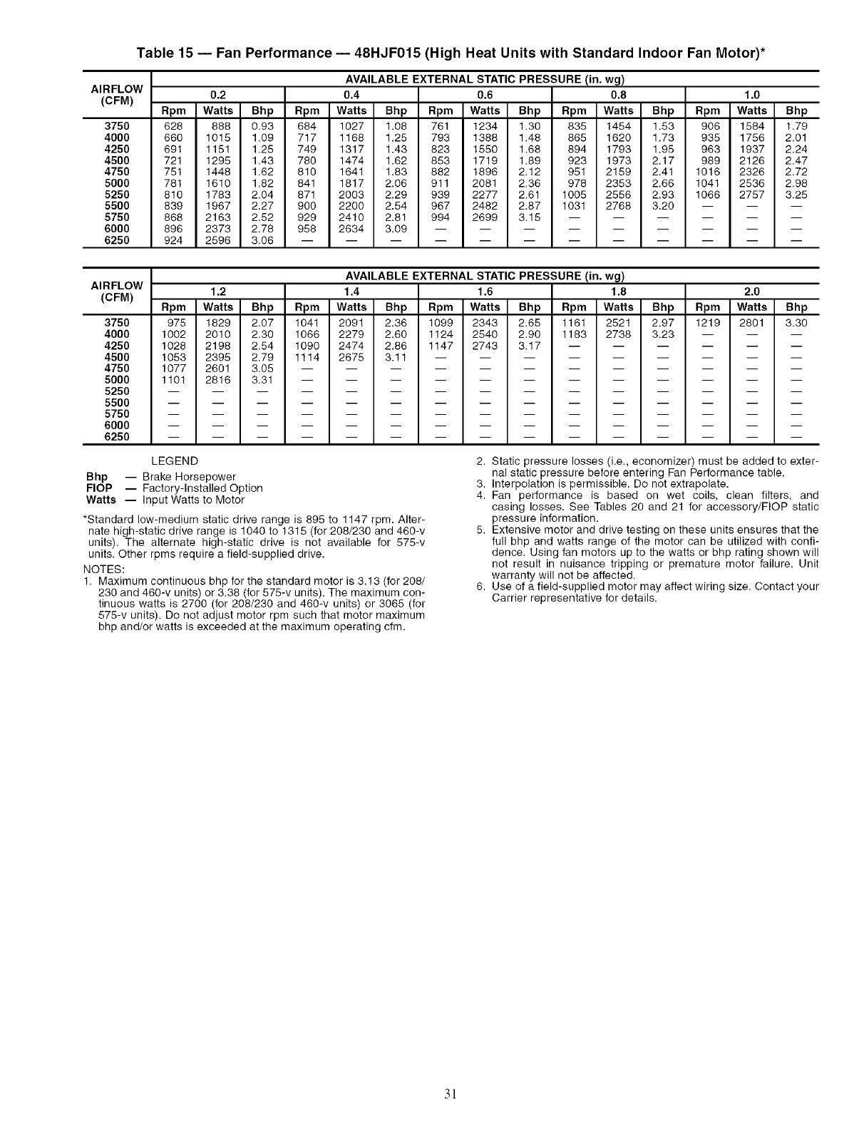
Table 15 -- Fan Performance -- 48HJF015 (High Heat Units with Standard Indoor Fan Motor)*
AIRFLOW
(CFM)
3750
4000
4250
4500
4750
5000
5250
5500
5750
6000
6250
AVAILABLE EXTERNAL STATIC PRESSURE (in. wg)
0.2 0.4 0.6 0.8 1.0
Rpm Watts Bhp Rpm Watts Bhp Rpm Watts Bhp Rpm Watts Bhp Rpm Watts Bhp
628 888 0.93 684 1027 1.08 761 1234 1.30 835 1454 1.53 906 1584 1.79
660 1015 1.09 717 1168 1.25 793 1388 1.48 865 1620 1.73 935 1756 2.01
691 1151 1.25 749 1317 1.43 823 1550 1.68 894 1793 1.96 963 1937 2.24
721 1295 1.43 780 1474 1.62 853 1719 1.89 923 1973 2.17 989 2126 2.47
751 1448 1.62 810 1641 1.83 882 1896 2.12 951 2159 2.41 1016 2326 2.72
781 1610 1.82 841 1817 2.06 911 2081 2.36 978 2353 2.66 1041 2536 2.98
810 1783 2.04 871 2003 2.29 939 2277 2.61 1005 2556 2.93 1066 2757 3.25
839 1967 2.27 900 2200 2.54 967 2482 2.87 1031 2768 3.20 -- -- --
868 2163 2.52 929 2410 2.81 994 2699 3.15 ......
896 2373 2.78 958 2634 3.09 .........
924 2596 3.06 ............
AIRFLOW
(CFM)
3750
4000
4250
4500
4750
5000
5250
5500
5750
6000
6250
AVAILABLE EXTERNAL STATIC PRESSURE (in. wg)
1.2 1.4 1.6 1.8 2.0
Rpm Watts Bhp Rpm Watts Bhp Rpm Watts Bhp Rpm Watts Bhp Rpm Watts Bhp
975 1829 2.07 1041 2091 2.36 1099 2343 2.65 1161 2521 2.97 1219 2801 3.30
1002 2010 2.30 1066 2279 2.60 1124 2540 2.90 1183 2738 3.23 -- -- --
1028 2198 2.54 1090 2474 2.86 1147 2743 3.17 ......
1053 2395 2.79 1114 2675 3.11 .........
1077 2601 3.05 ............
1101 2816 3.31 ............
LEGEND
Bhp -- Brake Horsepower
FlOP -- Factory-Installed Option
Watts -- Input Watts to Motor
*Standard low-medium static drive range is 895 to 1147 rpm. Alter-
nate high-static drive range is 1040 to 1315 (for 208/230 and 460-v
units). The alternate high-static drive is not available for 575-v
units. Other rpms require a field-supplied drive.
NOTES:
1. Maximum continuous bhp for the standard motor is 3.13 (for 208/
230 and 460-v units) or 3.38 (for 575-v units). The maximum con-
tinuous watts is 2700 (for 208/230 and 460-v units) or 3065 (for
576-v units). Do not adjust motor rpm such that motor maximum
bhp and/or watts is exceeded at the maximum operating cfm.
2. Static pressure losses (i.e., economizer) must be added to exter-
nal static pressure before entering Fan Performance table.
3. Interpolation is permissible. Do not extrapolate.
4. Fan performance is based on wet coils, clean filters, and
casing losses. See Tables 20 and 21 for accessory/FlOP static
pressure information.
5. Extensive motor and drive testing on these units ensures that the
full bhp and watts range of the motor can be utilized with confi-
dence. Using fan motors up to the watts or bhp rating shown will
not result in nuisance tripping or premature motor failure. Unit
warranty will not be affected.
6. Use of a field-supplied motor may affect wiring size. Contact your
Carrier representative for details.
3!
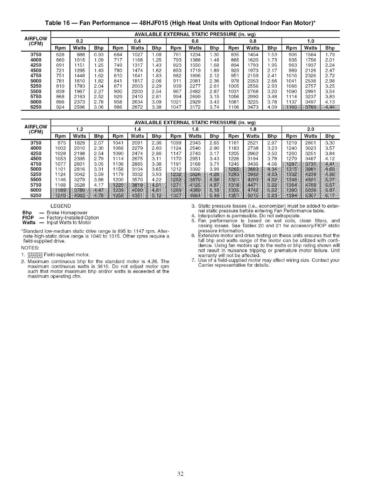
Table 16 -- Fan Performance -- 48HJF015 (High Heat Units with Optional Indoor Fan Motor)*
AIRFLOW
(CFM)
3750
4000
4250
4500
4750
5000
5250
5500
5750
6000
6250
AVAILABLE EXTERNAL STATIC PRESSURE (in. wg)
0.2 0.4 0.6 0.8 1.0
Rpm Watts Bhp Rpm Watts Bhp Rpm Watts Bhp Rpm Watts Bhp Rpm Watts Bhp
628 888 0,93 684 1027 1,08 761 1234 1,30 835 1454 1,53 906 1584 1,79
660 1015 1.09 717 1168 1.25 793 1388 1.48 865 1620 1.73 935 1756 2.01
691 1151 1.25 749 1317 1,43 823 1550 1.68 894 1793 1.95 963 1937 2.24
721 1295 1.43 780 1474 1.62 853 1719 1.89 923 1973 2.17 989 2126 2.47
751 1448 1.62 810 1641 1.83 882 1896 2.12 951 2159 2.41 1016 2326 2.72
781 1610 1.82 841 1817 2.06 911 2081 2.36 978 2353 2.66 1041 2536 2.98
810 1783 2,04 871 2003 2.29 939 2277 2.61 1005 2556 2.93 1066 2757 3.25
839 1967 2.27 900 2200 2.54 967 2482 2.87 1031 2768 3.20 1090 2991 3.54
868 2163 2.52 929 2410 2.81 994 2699 3.15 1056 2990 3.48 1114 3237 3.83
896 2373 2.78 958 2634 3.09 1021 2929 3.43 1081 3225 3.78 1137 3497 4.13
924 2596 3.06 986 2872 3.38 1047 3172 3.74 1106 3473 4.09
AIRFLOW
(CFM) 1.2
Rpm Watts Bhp Rpm Watts Bhp
3750 975 1829 2.07 1041 2091 2.36
4000 1002 2010 2.30 1066 2279 2.60
4250 1028 2198 2.54 1090 2474 2.86
4500 1053 2395 2.79 1114 2675 3.11
4750 1077 2601 3.05 1136 2885 3.38
5000 1101 2816 3.31 1158 3104 3.65
5250 1124 3042 3.59 1179 3332 3.93
5500 1146 3279 3.88 1200 3570 4.22
5750 1168 3528 4.17 iiiii_i220 iiiiiii_i_' i iiii!_ii_iiii!ii'
6000 i _i_il ii_89iii,i,i,iiiiii_!_iiiil i_ii_3_!iiiiiil_08_i!iiiiii _i_iiiiiii!!i
6250 iiiiiii_,!,_!!!lliii14062:1:iiii_iiTBiiiiiiiiiiii_,!5_ii _ iiiii_ii_!!! ;
AVAILABLE EXTERNAL STATIC PRESSURE (in. wg)
1.4 1.6 1.8 2.0
Rpm Watts Bhp Watts Bhp
1099 2343 2.65 2521 2.97
124 2540 2.90 2738 3.23
147 2743 3.17 2962 3.50
170 2951 3.43 3194 3.78
191 3168 3.71 3435 4.06
1212 3392 3.99 363 l
Nti N _i Nt_B : 'N,_ NN'
,,,,,,,,sm
LEGEND
Bhp -- Brake Horsepower
FlOP -- Factory-Installed Option
Watts -- Input Watts to Motor
*Standard low-medium static drive range is 895 to 1147 rpm. Alter-
nate high-static drive range is 1040 to 1315. Other rpms require a
field-supplied drive.
NOTES:
1. Field-supplied motor.
2. Maximum continuous bhp for the standard motor is 4.26. The
maximum continuous watts is 3610. Do not adjust motor rpm
such that motor maximum bhp and/or watts is exceeded at the
maximum operating cfm.
3. Static pressure losses (i.e., economizer) must be added to exter-
nal static pressure before entering Fan Performance table.
4. Interpolation is permissible. Do not extrapolate.
5. Fan performance is based on wet coils, clean filters, and
casing losses. See Tables 20 and 21 for accessory/FlOP static
pressure information.
6. Extensive motor and drive testing on these units ensures that the
full bhp and watts range of the motor can be utilized with confi-
dence. Using fan motors up to the watts or bhp rating shown will
not result in nuisance tripping or premature motor failure. Unit
warranty will not be affected.
7. Use of a field-supplied motor may affect wiring size. Contact your
Carrier representative for details.
32
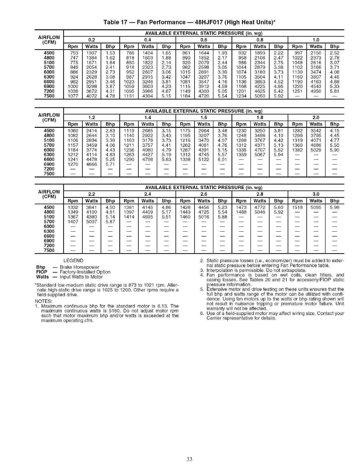
AIRFLOW
(CFM)
4500
4800
5100
5700
6000
6300
6600
6900
7200
7500
Table 17 -- Fan Performance -- 48HJF017 (High Heat Units)*
AVAILABLE EXTERNAL STATIC PRESSURE (in. wg)
0.2 0.4 0.6 0.8 1.0
Rpm Watts Bhp Rpm Watts Bhp Rpm Watts Bhp Rpm Watts Bhp Rpm Watts Bhp
753 1307 1.53 786 1404 1.65 861 1644 1.93 932 1893 2.22 997 2150 2.52
747 1384 1.62 818 1603 1.88 890 1852 2.17 958 2108 2.47 1022 2373 2.78
775 1571 1.84 850 1822 2.14 920 2079 2.44 986 2344 2.75 1048 2616 3.07
849 2054 2,41 918 2323 2,73 982 2598 3,05 1044 2879 3,38 1102 3166 3.71
886 2329 2,73 952 2607 3,06 1015 2891 3,39 1074 3180 3,73 1130 3474 4.08
924 2628 3,08 987 2915 3,42 1047 3207 3.76 1105 3504 4,11 1160 3807 4.46
962 2951 3,46 1023 3246 3.81 1081 3547 4.16 1136 3853 4.52 1190 4163 4,88
1000 3298 3,87 1059 3603 4.23 1115 3912 4,59 1168 4225 4,96 1220 4543 5,33
1038 3672 4,31 1095 3986 4,67 1149 4303 5,05 1201 4625 5,42 1251 4950 5.81
1077 4072 4.78 1131 4394 5.15 1184 4720 5.54 1234 5050 5.92 -- -- --
AIRFLOW
(CFM)
4500
4800
5100
5700
6000
6300
6600
6900
7200
7500
AVAILABLE EXTERNAL STATIC PRESSURE (in. wg)
1.2 1.4 1.6 1.8 2.0
Rpm Watts Bhp Rpm Watts Bhp Rpm Watts Bhp Rpm Watts Bhp Rpm Watts Bhp
1060 2414 2.83 1119 2685 3.15 1175 2964 3.48 1230 3250 3.81 1282 3542 4.15
1082 2644 3,10 1140 2922 3,43 1195 3207 3.76 1248 3498 4.10 1299 3795 4.45
1106 2894 3,39 1163 3178 3,73 1216 3470 4.07 1268 3767 4,42 1319 4071 4,77
1157 3459 4,06 1211 3757 4,41 1262 4061 4,76 1312 4371 5,13 1360 4686 5,50
1184 3774 4,43 1236 4080 4,79 1287 4391 5.15 1335 4707 5,52 1382 5029 5.90
1212 4114 4.83 1263 4427 5.19 1312 4745 5.57 1359 5067 5.94 -- -- --
1241 4478 5.25 1290 4798 5.63 1338 5122 6.01 ......
1270 4866 5.71 ............
AIRFLOW
(CFM)
4500
4800
5100
5700
6000
6300
6600
6900
7200
7500
AVAILABLE EXTERNAL STATIC PRESSURE (in. wg)
2.2 2.4 2.6 2.8 3.0
Rpm Watts Bhp Rpm Watts Bhp Rpm Watts Bhp Rpm Watts Bhp Rpm Watts Bhp
1332 3841 4,50 1381 4145 4,86 1428 4456 5,23 1473 4772 5,60 1518 5095 5.98
1349 4100 4.81 1397 4409 5.17 1443 4725 5.54 1488 5046 5.92 -- -- --
1367 4380 5.14 1414 4695 5.51 1460 5016 5.88 ......
1407 5007 5.87 ............
LEGEND
Bhp -- Brake Horsepower
FlOP -- Factory-Installed Option
Watts -- Input Watts to Motor
*Standard low-medium static drive range is 873 to 1021 rpm. Alter-
nate high-static drive range is 1025 to 1200. Other rpms require a
field-supplied drive.
NOTES:
1. Maximum continuous bhp for the standard motor is 6.13, The
maximum continuous watts is 5180. Do not adjust motor rpm
such that motor maximum bhp and/or watts is exceeded at the
maximum operating cfm.
2. Static pressure losses (i.e., economizer) must be added to exter-
nal static pressure before entering Fan Performance table.
3. Interpolation is permissible. Do not extrapolate.
4. Fan performance is based on wet coils, clean filters, and
casing losses. See Tables 20 and 21 for accessory/FlOP static
pressure information.
5. Extensive motor and drive testing on these units ensures that the
full bhp and watts range of the motor can be utilized with confi-
dence. Using fan motors up to the watts or bhp rating shown will
not result in nuisance tripping or premature motor failure. Unit
warranty will not be affected.
6. Use of a field-supplied motor may affect wiring size. Contact your
Carrier representative for details.
33
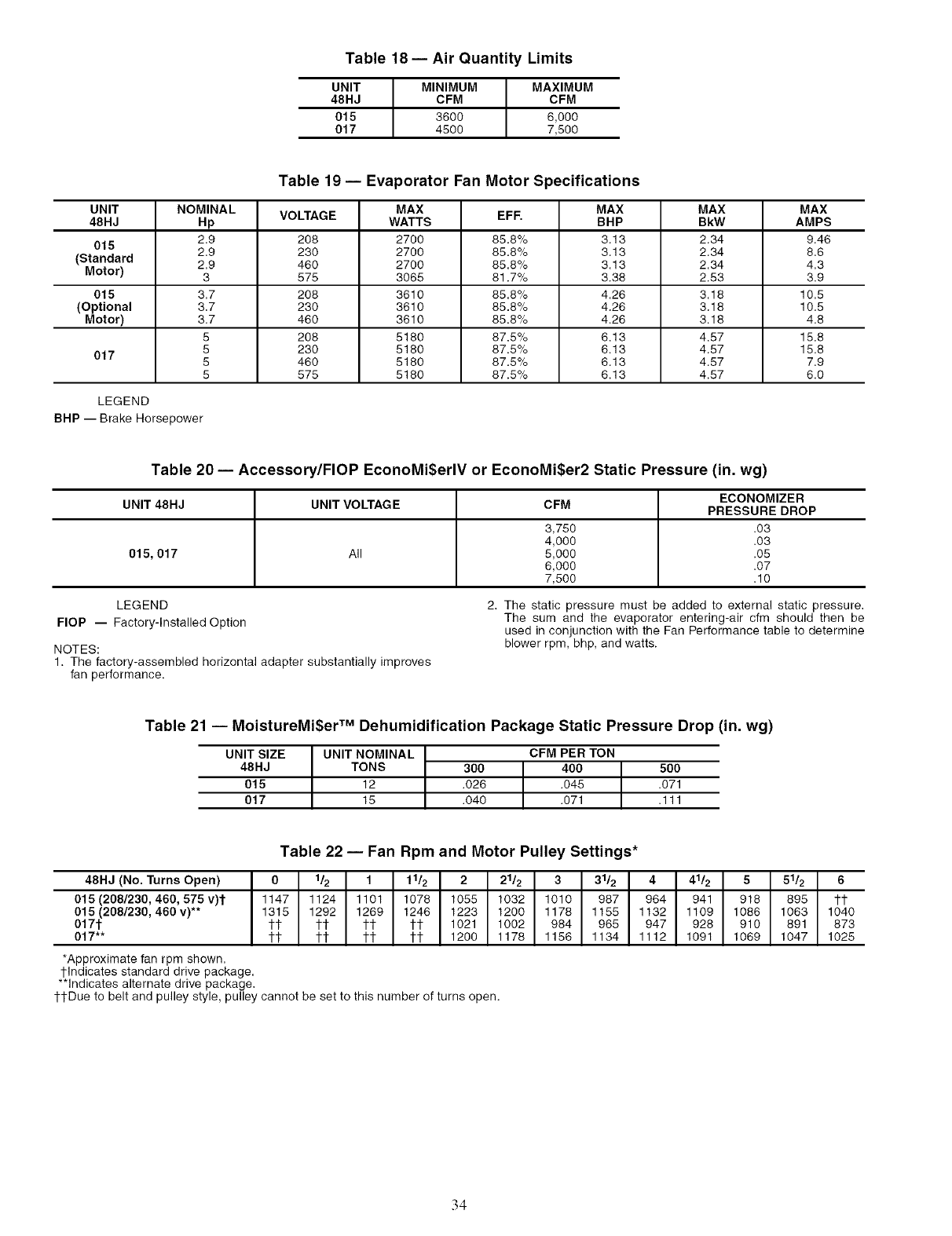
Table 18 -- Air Quantity Limits
UNIT MINIMUM MAXIMUM
48HJ CFM CFM
015 3600 6,000
017 4500 7,500
Table 19- Evaporator Fan Motor Specifications
UNIT NOMINAL VOLTAGE MAX EFF. MAX MAX MAX
48HJ Hp WATTS BHP BkW AMPS
015 2.9 208 2700 85.8% 3.13 2.34 9.46
2.9 230 2700 85.8% 3.13 2.34 8.6
(Standard 2.9 460 2700 85.8% 3.13 2.34 4.3
Motor) 3 575 3065 81.7% 3.38 2.63 3.9
015 3.7 208 3610 85.8% 4.26 3.18 10.5
(Optional 3.7 230 3610 85.8% 4.26 3.18 10.5
Motor) 3.7 460 3610 85.8% 4.26 3.18 4.8
5 208 5180 87.5% 6.13 4.57 15.8
017 5 230 5180 87.5% 6.13 4.57 15.8
5 460 5180 87.5% 6.13 4.57 7.9
5 575 5180 87.5% 6.13 4.67 6.0
LEGEND
BHP -- Brake Horsepower
Table 20 -- Accessory/FlOP EconoMiSerlV or EconoMiSer2 Static Pressure (in. wg)
ECONOMIZER
UNIT 48HJ UNIT VOLTAGE CFM PRESSURE DROP
3,750 .03
4,000 .03
015, 017 All 5,000 .06
6,000 .07
7,500 .10
LEGEND
FlOP -- Factory-Installed Option
NOTES:
1. The factory-assembled horizontal adapter substantially improves
fan performance.
2. The static pressure must be added to external static pressure.
The sum and the evaporator entering-air cfm should then be
used in conjunction with the Fan Performance table to determine
blower rpm, bhp, and watts.
Table 21 -- MoistureMi$er TM Dehumidification Package Static Pressure Drop (in. wg)
UNIT SIZE UNIT NOMINAL CFM PER TON
48HJ TONS 300 400 500
015 12 .026 .045 .071
017 15 .040 .071 .111
Table 22 -- Fan Rpm and Motor Pulley Settings*
48HJ (No. Turns Open) 0 1/2 1 11/2 2 21/2 3 31/2 4 41/2 5 51/2 6
015 (208/230, 460, 575 v)t 1147 1124 1101 1078 1055 1032 1010 987 964 941 918 895 tt
015 (208/230, 460 v)** 1315 1292 1269 1246 1223 1200 1178 1155 1132 1109 1086 1063 1040
017t tl- tt tt tt 1021 1002 984 968 947 928 910 891 873
017"* tl- tt tt tt 1200 1178 1156 1134 1112 1091 1069 1047 1025
*Approximate fan rpm shown.
tlndicates standard drive package.
**Indicates alternate drive package.
1-tDue to belt and pulley style, pulley cannot be set to this number of turns open.
34
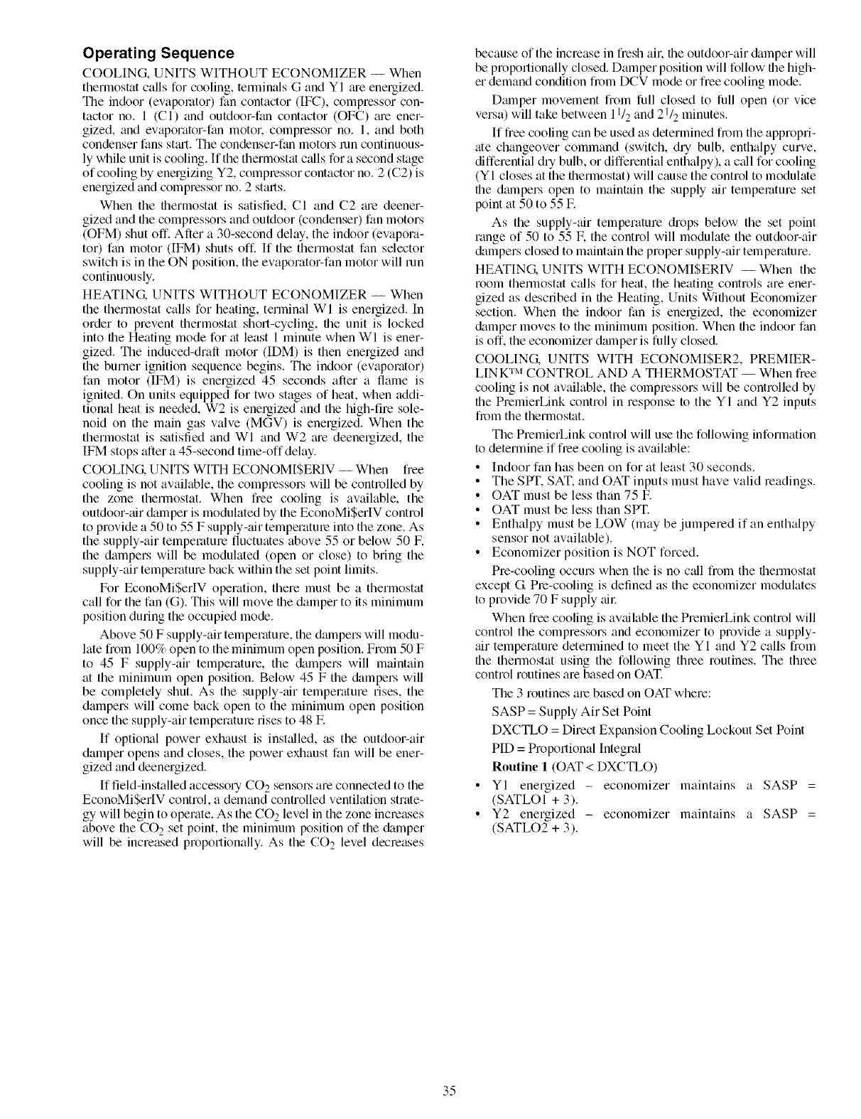
Operating Sequence
COOLING, UNITS WITHOUT ECONOMIZER -- When
thermostat calls for cooling, terminals G and YI me energized.
The indoor (evapolator) fan contactor (IFC), compressor con-
tactor no. 1 (C l) and outdoor-fan contactor (OFC) me ener-
gized, and evaporator-fan motol: compressor no. 1, and both
condenser fans st_ul. The condenser-fan motors mn continuous-
ly while unit is cooling. If the thermostat c_dls for a second stage
of cooling by energizing Y2, complessor contactor no. 2 (C2) is
energized and compressor no. 2 stalls.
When the thermostat is satisfied, CI and C2 me deener-
gized and the compressors and outdoor (condenser) fan motors
(OFM) shut off. After a 30-second delay, the indoor (evapora-
tor) fan motor (IFM) shuts off. If the therlnostat fan selector
switch is in the ON position, the evaporator-fan motor will run
continuously.
HEATING. UNITS WITHOUT ECONOMIZER -- When
the thermostat calls for heating, terminal WI is energized. In
order to prevent thermostat short-cycling, the unit is locked
into the Heating mode for at least 1 minute when WI is ener-
gized. The induced-draft motor (IDM) is then energized and
the burner ignition sequence begins. The indoor (evaporator)
fan motor (IFM) is energized 45 seconds after a flame is
ignited. On units equipped for two stages of heat, when addi-
tional heat is needed, W2 is enelgized and the high-fire sole-
noid on the main gas valve (MGV) is energized. When the
thermostat is satisfied and WI and W2 me deenergized, the
IFM stops after a 45-second time-off delay.
COOLING. UNITS WITH ECONOMISERIV -- When free
cooling is not available, the compressol_ will be controlled by
the zone thermostat. When free cooling is available, the
outdoor-air &unper is modulated by the EconoMiSerlV control
to provide a 50 to 55 F supply-air temperatme into the zone. As
the supply-air temperature fluctuates above 55 or below 50 E
the dampers will be modulated (open or close) to bring the
supply-air temperature back within the set point limits.
For EconoMiSerlV operation, there must be a thermostat
call for the fan (G). This will move the damper to its minimum
position during the occupied mode.
Above 50 F supply-air temperature, the dalnpers will modu-
late from 100% open to the minimum open position. From 50 F
to 45 F supply-air temperature, the &tmpers will maintain
at the minimum open position. Below 45 F the &tmpers will
be completely shut. As the supply-air temperature rises, the
dampers will come back open to the minimum open position
once the supply-air temperature rises to 48 E
If optional power exhaust is inst_dled, as the outdoor-air
damper opens and closes, the power exhaust fan will be ener-
gized and deenergized.
If field-installed accessory CO 2 sensors are connected to the
EconoMiSerIV control, a demand controlled ventilation strate-
gy will begin to operate. As the CO 2 level in the zone increases
above the CO 2 set point, the minimum position of the &tmper
will be increased proportionally. As the CO 2 level decreases
because of the increase in fresh ail: the outdoor-air &tmper will
be proportionally closed. Damper position will follow file high-
er demand condition from DCV mode or free cooling mode.
Dmnper movement from full closed to full open (or vice
versa) will take between I l/2 and 21/2 minutes.
If free cooling can be used as determined from the appropri-
ate changeover command (switch, dry bulb, enthalpy curve,
differential dry bulb, or differential enthalpy), a call for cooling
(YI closes at the thermostat) will cause the control to modulate
the dmnpers open to maintain the supply air temperature set
point at 50 to 55 E
As the supply-air temperature drops below the set point
range of 50 to 55 F. the control will modulate the outdoor-air
&Lmpers closed to maintain the proper supply-air temperature.
HEATING. UNITS WITH ECONOMISERIV -- When the
room thermostat c_dls for heat, the heating controls are ener-
gized as described in the Heating, Units Without Economizer
section. When the indoor fan is energized, the economizer
&Lmper moves to the minimum position. When the indoor fan
is off. the economizer dmnper is fully closed.
COOLING. UNITS WITH ECONOMI$ER2, PREMIER-
LINK TM CONTROL AND A THERMOSTAT -- When free
cooling is not available, the compressors will be controlled by
file PremierLink control in response to the YI and Y2 inputs
from the thermostat.
The PremierLink control will use the following information
to determine if flee cooling is available:
• Indoor fan has been on for at least 30 seconds.
• The SPT. SAT. and OAT inputs must have valid readings.
• OAT must be less than 75 E
• OAT must be less than SPT.
• Enthalpy must be LOW (may be jumpered if an enthalpy
sensor not available).
• Economizer position is NOT forced.
Pre-cooling occurs when the is no c_dl from the thermostat
except G Pie-cooling is defined as the economizer modulates
to provide 70 F supply all:
When free cooling is awtilable the PremierLink control will
control the compressors and economizer to provide a supply-
air temperature determined to meet the YI and Y2 calls from
file thermostat using the following thlee routines. The three
control routines are based on OAT.
The 3 routines me based on OAT where:
SASP = Supply Air Set Point
DXCTLO = Direct Expansion Cooling Lockout Set Point
PID = Proportional Integral
Routine 1 (OAT < DXCTLO)
YI energized - economizer maintains a SASP =
(SATLOI + 3).
Y2 energized - economizer maintains a SASP =
(SATLO2 + 3).
35
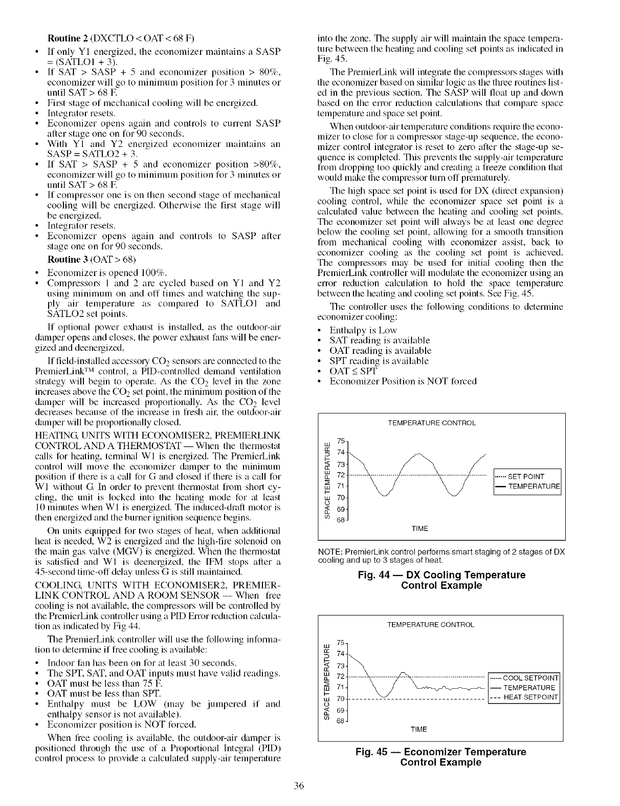
Routine 2 (DXCTLO < OAT < 68 F)
• If only YI energized, the economizer maintains a SASP
= (SATLOI + 3).
•If SAT > SASP + 5 and economizer position > 80%,
economizer will go to minimum position for 3 minutes or
until SAT > 68 E
• First stage of mechanical cooling will be energized.
•Integrator resets.
• Economizer opens again and controls to current SASP
after stage one on for 90 seconds.
• With YI and Y2 energized economizer maintains an
SASP = SATLO2 + 3.
• If SAT > SASP + 5 and economizer position >80%,
economizer will go to minimum position for 3 minutes or
until SAT > 68 E
• If compressor one is on then second stage of mechanical
cooling will be energized. Otherwise the first stage will
be energized.
• Integrator resets.
• Economizer opens again and controls to SASP after
stage one on for 90 seconds.
Routine 3 (OAT > 68)
• Economizer is opened 100%.
•Compressors 1 and 2 are cycled based on YI and Y2
using minimum on and off times and watching the sup-
ply air temperature as compared to SATLOI and
SATLO2 set points.
If optional power exhaust is installed, as the outdoor-air
damper opens and closes, the power exhaust fans will be ener-
gized and deenergizedi
If field-installed accessory CO 2 sensors are connected to the
PremierLink TM control, a PID-controlled demand ventilation
strategy will begin to operate. As the CO 2 level in the zone
increases above the CO 2 set point, the minimum position of the
dmnper will be increased proportionally. As the CO 2 level
decreases because of the increase in fresh all: the outdoor-air
dmnper will be proportionally closed.
HEATING. UNITS WITH ECONOMISER2, PREMIERLINK
CONTROL AND A THERMOSTAT -- When the thermostat
calls for heating, terminal WI is energized. The PremierLink
control will move the economizer damper to the minimum
position if there is a qdl for G and closed if there is a call for
WI without G In order to prevent thermostat from short cy-
cling, the unit is locked into the heating mode for at least
10 minutes when WI is energized. The induced-draft motor is
then energized and the burner ignition sequence begins.
On units equipped for two stages of heat, when additional
heat is needed, W2 is energized and the high-fire solenoid on
the main gas valve (MGV) is energized. When the thermostat
is satisfied and WI is deenergized, the IFM stops after a
45-second time-off delay unless G is still maintained.
COOLING. UNITS WITH ECONOMISER2, PREMIER-
LINK CONTROL AND A ROOM SENSOR -- When free
cooling is not available, the compressors will be controlled by
the PremierLink controller using a PIE) Error reduction calcula-
tion as indicated by Fig 44.
The PremierLink controller will use the following informa-
tion to determine if free cooling is available:
• Indoor fan has been on for at least 30 seconds.
• The SPT. SAT. and OAT inputs must have valid readings.
• OAT must be less than 75 E
• OAT must be less than SPT.
• Enthalpy must be LOW (may be jumpered if and
enthalpy sensor is not available).
• Economizer position is NOT forcedi
When fiee cooling is available, the outdoor-air damper is
positioned through the use of a Proportional Integral (PID)
control process to provide a calculated supply-air temperature
into the zone. The supply air will maintain the space tempera-
ture between the heating and cooling set points as indicated in
Fig. 45.
The PremierLink will integrate the compressors stages with
the economizer based on similtu logic as the three routines list-
ed in the previous section. The SASP will float up and down
based on the error leduction c_dculations that compare space
temperature and space set point.
When outdoor-air temperature conditions require the econo-
mizer to close for a complessor stage-up sequence, the econo-
mizer control integrator is reset to zero after the stage-up se-
quence is completed. This prevents the supply-air temperature
from dropping too quickly and creating a freeze condition that
would make the compressor turn off prematurely.
The high space set point is used for DX (dilect expansion)
cooling control, while the economizer space set point is a
calculated value between the heating and cooling set points.
The economizer set point will always be at least one degree
below the cooling set point, allowing for a smooth transition
from mechanical cooling with economizer assist, back to
economizer cooling as the cooling set point is achieved.
The compressors may be used for initial cooling then the
PremierLink controller will modulate the economizer using an
error reduction calculation to hold the space temperature
between the heating and cooling set points. See Fig. 45.
The controller uses the following conditions to determine
economizer cooling:
• Enthalpy is Low
• SAT reading is available
• OAT reading is available
• SPT reading is available
• OAT < SPT
• Economizer Position is NOT forced
75,
t13
744
'_ 734
nm 724
71 4
I-
w 704
o
694
co 68 J
TEMPERATURE CONTROL
TIME
...... SET POINT
_TEMPERATURE
NOTE: PremierLink control performs smart staging of 2 stages of DX
cooling and up to 3 stages of heat.
Fig. 44 -- DX Cooling Temperature
Control Example
TEMPERATURECONTROL
cc 74
73 ......... ....................................F_COOLSETPO,NT
__ 71 ] X /I-- TEMPERATURE
ow ii j v L___ HEAT SETPOINT
TIME
Fig. 45 -- Economizer Temperature
Control Example
36
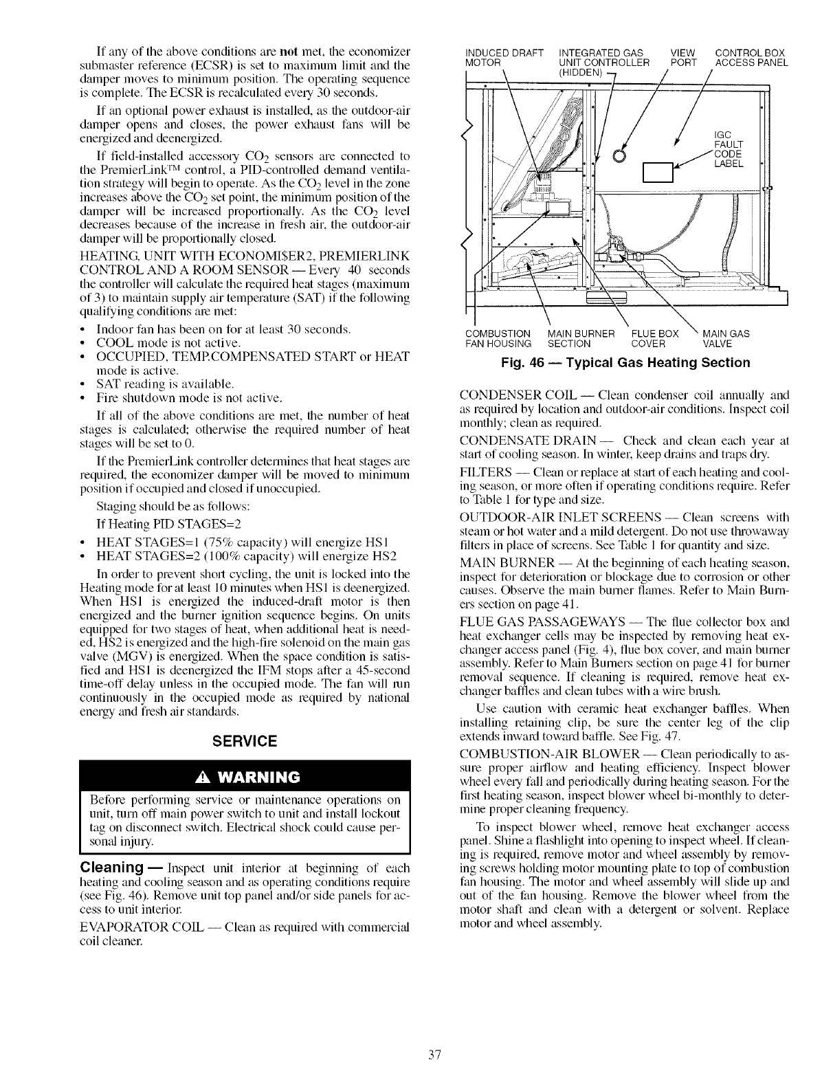
If any of the above conditions am not met, file economizer
submaster reference (ECSR) is set to maximum limit and the
damper moves to minimum position. The operating sequence
is complete. The ECSR is rectflculated every 30 seconds.
If gin optional power exhaust is installed, as file outdoor-air
damper opens and closes, the power exhaust fans will be
energized and deenergizedi
If field-installed accessory CO 2 sensors are connected to
the PremierLink TM control, a PID-controlled demand ventila-
tion strategy will begin to operate. As the CO 2 level in the zone
increases above file CO 2 set point, the minimum position of the
damper will be increased proportionally. As the CO 2 level
decreases because of the increase in flesh air. the outdoor-air
damper will be proportionally closed.
HEATING. UNIT WITH ECONOMISER2, PREMIERLINK
CONTROL AND A ROOM SENSOR -- Every 40 seconds
the controller will calculate the required heat stages (maximum
of 3) to maintain supply air temperature (SAT) if the following
qufdifying conditions are met:
• Indoor fan has been on for fit least 30 seconds.
• COOL mode is not active.
• OCCUPIED, TEMRCOMPENSATED START or HEAT
mode is active.
• SAT reading is available.
• Fire shutdown mode is not active.
If all of the above conditions are met, the number of heat
stages is cfdculated; otherwise file required number of heat
stages will be set to 0.
If file PremierLink controller determines that heat stages are
required, the economizer &tmper will be moved to minimum
position if occupied and closed if unoccupied.
Staging should be as follows:
If Heating HD STAGES=2
• HEAT STAGES=I (75% capacity) will energize HSI
• HEAT STAGES=2 (100% capacity) will energize HS2
In order to prevent short cycling, the unit is locked into the
Heating mode for fit least 10 minutes when HS 1 is deenergizedi
When HSI is energized the induced-di'aft motor is then
energized and the burner ignition sequence begins. On units
equipped for two stages of heat, when additional heat is need-
ed, HS2 is energized and the high-fire solenoid on the main gas
valve (MGV) is energized. When the space condition is satis-
fied and HSI is deenergized the IFM stops after a 45-second
time-off delay unless in the occupied mode. The fan will mn
continuously in the occupied mode as required by national
energy and fresh air standards.
SERVICE
Before performing service or maintenance operations on
unit, turn off main power switch to unit and install lockout
tag on disconnect switch. Electrical shock could cause per-
somd injury.
Cleaning- Inspect unit interior at beginning of each
heating and cooling season and as operating conditions require
(see Fig. 46). Remove unit top panel and/or side panels for ac-
cess to unit interioc
EVAPORATOR COIL -- Clean as required with commercifd
coil cleanel:
INDUCED DRAFT
MOTOR
•\ Ji77' _
i tl __. ilO _ /GCLT
o :275,2
FAN HOUSING SECTION COVER VALVE
INTEGRATED GAS VIEW CONTROL BOX
UNIT CONTROLLER PORT ACCESS PANEL
"7
Fig. 46 -- Typical Gas Heating Section
CONDENSER COIL- Clean condenser coil annually and
as required by location and outdoor-air conditions. Inspect coil
monthly; clean as required.
CONDENSATE DRAIN- Check and clean each year fit
start of cooling season. In wintek keep drains and traps dry.
FILTERS -- Clean or replace fit stmt of each heating and cool-
ing season, or more often if operating conditions require. Refer
to Table 1 for type and size.
OUTDOOR-AIR INLET SCREENS -- Clean screens with
steam or hot water and a mild detergent. Do not use throwaway
filters in place of screens. See Table 1 for quantity and size.
MAIN BURNER -- At the beginning of each heating season,
inspect for deterioration or blockage due to corrosion or other
causes. Observe the main burner flalnes. Refer to Main Burn-
ers section on page 41.
FLUE GAS PASSAGEWAYS -- The flue collector box and
heat exchanger cells may be inspected by removing heat ex-
changer access panel (Fig. 4), flue box cover, and main burner
assembly. Refer to Main Burners section on page 41 for burner
removal sequence. If cleaning is lequired, remove heat ex-
changer baffles and clean tubes with a wire brash.
Use caution with ceramic heat exchanger baffles. When
installing retaining clip, be sure the center leg of the clip
extends inward toward baffle. See Fig. 47.
COMBUSTION-AIR BLOWER -- Clean periodically to as-
sure proper airflow and heating efficiency. Inspect blower
wheel every fall and periodicfdly during heating season. For the
first heating season, inspect blower wheel bi-monthly to deter-
mine proper cleaning frequency.
To inspect blower wheel, remove heat exchanger access
panel. Shine a flashlight into opening to inspect wheel. If clean-
ing is required, remove motor and wheel assembly by remov-
ing screws holding motor mounting plate to top of combustion
fan housing. The motor and wheel assembly will slide up and
out of the fan housing. Remove the blower wheel from the
motor shaft and clean with a detergent or solvent. Replace
motor and wheel assembly.
37
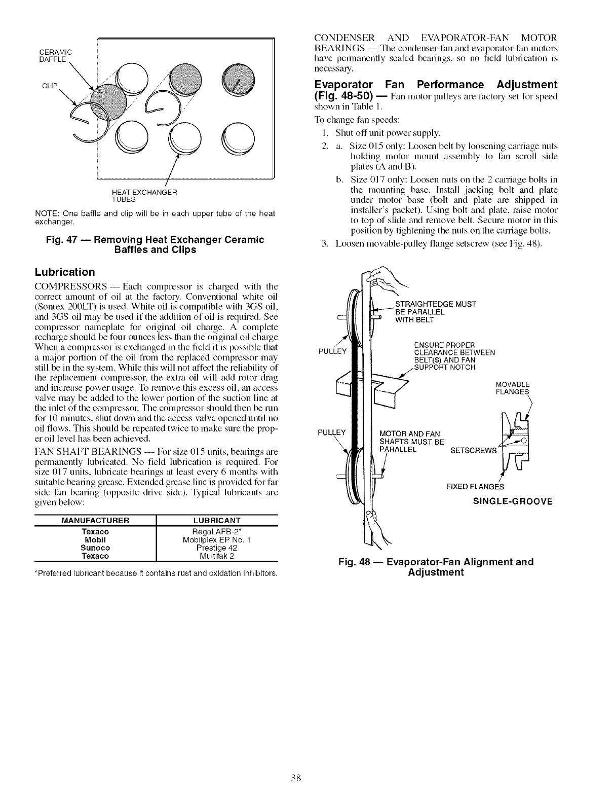
CERAMIC
BAFFLE
CLIP_
/
HEAT EXCHANGER
TUBES
NOTE: One baffle and clip will be in each upper tube of the heat
exchanger.
Fig. 47 -- Removing Heat Exchanger Ceramic
Baffles and Clips
Lubrication
COMPRESSORS- Each compressor is charged with the
correct amount of oil fit the factory. Conventional white oil
(Sontex 200LT) is used. White oil is compatible with 3GS oil,
and 3GS oil may be used if the addition of oil is required. See
compressor nmneplate for ongimd oil chmge. A complete
recharge should be four ounces less than file original oil charge
When a compressor is exchanged in the field it is possible that
a major portion of the oil from the replaced compressor may
still be in file system. While this will not affect the reliability of
the replacement compressok the extra oil will add rotor drag
and increase power usage. To remove this excess oil, fin access
vfdve may be added to the lower portion of the suction line at
the inlet of the compressol: The compressor should then be run
for 10 minutes, shut down and the access valve opened until no
oil flows. This should be repeated twice to make sure the prop-
er oil level has been achieved.
FAN SHAFT BEARINGS -- For size 015 units, bearings me
permanently lubricated. No field lubrication is required. For
size 017 units, lubricate bearings fit least every 6 months with
suitable bearing grease. Extended grease line is provided for far
side fan bearing (opposite drive side). Typical lubricants me
given below:
MANUFACTURER ILUBRICANT
Texaco Regal AFB-2*
Mobil Mobilplex EP No. 1
Sunoco Prestige 42
Texaco Multifak 2
*Preferred lubricant because it contains rust and oxidation inhibitors.
CONDENSER AND EVAPORATOR-FAN MOTOR
BEARINGS -- The condenser-fan and evaporator-fan motors
have permanently sealed bearings, so no field lubrication is
necessaq.
Evaporator Fan Performance Adjustment
(Fig. 48-50) -- Fan motor pulleysare factol7 set for speed
shown in Table I.
To change fan speeds:
I. Shut off unit power supply.
2. a. Size 015 only: Ix_osen belt by loosening cmriage nuts
holding motor mount assembly to fan scroll side
plmes (A and B).
b. Size 017 only: Loosen nuts on the 2 cmriage bolts in
the mounting base. [nstall jacking bolt find plate
under motor base (bolt fred plate are shipped in
instfdler's packet). Using bolt and plate, raise motor
to top of slide and remove belt. Secure motor in this
position by tightening the nuts on the carriage bolts.
3. Loosen movable-pulley flange setscrew (see Fig. 48).
PULLEY
PULLEY
STRAIGHTEDGE MUST
WITH BELT
ENSURE PROPER
CLEARANCE BETWEEN
BELT(S) AND FAN
MOTOR AND FAN
SHAFTS MUST BE
PARALLEL
MOVABLE
FLANGES
SETSCREWS_
FIXED FLANGES
SINGLE-GROOVE
Fig. 48 -- Evaporator-Fan Alignment and
Adjustment
38
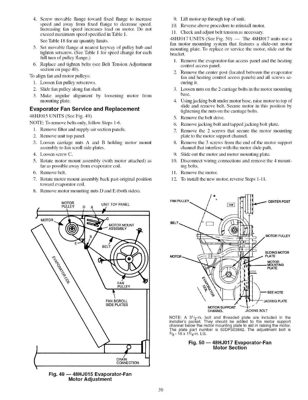
4. Screw movable flange toward fixed flange to increase
speed and away from fixed flange to decrease speed.
Increasing fan speed increases load on motol: Do not
exceed maximum speed specified in Table 1.
See Table 18 for air quantity limits.
5. Set movable flange at nemest keyway of pulley hub and
tighten setscrew. (See Table 1 for speed change for each
full turn of pulley flange.)
6. Replace and tighten belts (see Belt Tension Adjustment
section on page 40).
To align fan and motor pulleys:
1. Loosen fan pulley setscrews.
2. Slide fan pulley along fan shaft.
3. Make angular alignment by loosening motor flom
mounting pkite.
Evaporator Fan Service and Replacement
48HJ015 UNITS (See Fig. 49)
NOTE: To remove belts only, follow Steps 1-6.
1. Remove filter and supply-air section panels.
2. Remove unit top panel.
3. Loosen caniage nuts A and B holding motor mount
assembly to fan scroll side plates.
4. Loosen screw C.
5. Rotate motor mount assembly (with motor attached) as
far as possible away from evaporator coil.
6. Remove belt.
7. Rotate motor mount assembly back past original position
toward evaporator coil.
8. Remove motor mounting nuts D and E (both sides).
MOTOR UNIT1-OPPANEL
POLLEYO p,
MOTOR '_'_MOTO R MOUNT
PULLEY
FAN SCROLL
SIDE PLATES
DRAIN
CONNECTION
Fig. 49 -- 48HJ015 Evaporator-Fan
Motor Adjustment
9. Lift motor up through top of unit.
10. Reverse above procedure to reinstall motol:
11. Check and adjust belt tension as necessary.
48HJ017 UNITS (See Fig. 50) -- The 48HJ017 units use a
fan motor mounting system that features a slide-out motor
mounting pkite. To replace or service the motor, slide out the
bracket.
1. Remove the evaporator-fan access panel and the heating
control access panel.
2. Remove the center post (located between the evaporator
fan and heating control access panels) and all screws se-
curing it.
3. Ix)osen nuts on the 2 cmriage bolts in the motor mounting
base.
4. Using jacking bolt under motor base, raise motor to top of
slide and remove belt. Secure motor in this position by
tightening the nuts on the carriage bolts.
5. Remove the belt drive.
6. Remove jacking bolt and tapped jacking bolt pkite.
7. Remove the 2 screws that secure the motor mounting
plate to the motor support channel.
8. Remove the 3 screws from the end of the motor support
channel that interfere with the motor slide path.
9. Slide out the motor and motor mounting pkite.
10. Disconnect wiring connections and remove the 4 mount-
ing bolts.
11. Remove the motol:
12. To install the new motol; reverse Steps 1-11.
FAN PU
MOTOR PULLEY
SLIDINGMOTOR
MOTOR _ PLATE
MOTOR
PLATE
\
MOTOR SUPPORT
CHANNEL JACKING BOLT
NOTE: A 31/2-in. bolt and threaded plate are included in the
installer's packet. They should be added to the motor support
channel below the motor mounting plate to aid in raising the motor.
The plate part number is 50DP503842. The adjustment bolt is
3/8 - 16 x 1_/4-in. LG.
Fig. 50- 48HJ017 Evaporator-Fan
Motor Section
39
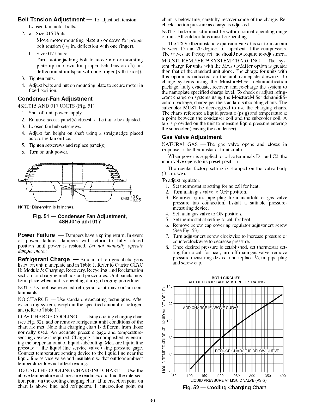
Belt Tension Adjustment -- To adjust belt tension:
I. Ix_osen fan motor bolts.
2. a. Size 015 Units:
Move motor mounting plate up or down for propel
belt tension (1/2 in. deflection with finger).
one
b. Size 017 Units:
Turn motor jacking bolt to move motor mounting
plate down for proper belt tension (3/8 in.
up or
deflection at midspan with one finger [9 lb forcel).
3. Tighten nuts.
4. Adjust bolts and nut on mounting plate to secure motor in
fixed position.
Condenser-Fan Adjustment
48HJ015 AND 017 UNITS (Fig. 51)
I. Shut off unit power supply.
2. Remove access panel(s) closest to the fan to be adjusted.
3. Ix_osen fan hub setscrews.
4. Adjust fan height on shaft using a straightedge placed
across the fan oliI]ce.
5. Tighten setscrews and replace panel(s).
6. Turn on unit powel:
, i T ........
NOTE: Dimension is in inches.
Fig. 51 i Condenser Fan Adjustment,
48HJ015 and 017
Power Failure -- Danpers have a spring return. In event
of power ftfihre, dampers will return to fully closed
position until power is restored. Do not manuall)" ol)erate
damper motor
Refrigerant Charge -- Amount of refrigerant ch_u'ge is
listed on unit nameplate and in Table I. Refer to Carrier GTAC
II; Module 5; Ch_uging, Recovery, Recycling, and Reclamation
section for charging methods and procedures. Unit panels must
be in place when unit is operating during charging procedure.
NOTE: Do not use recycled refrigerant as it may contain con-
taminants.
NO CHARGE -- Use standard evacuating techniques. After
evacuating system, weigh in the specified amount of refriger-
ant (refer to Table l ).
LOW CHARGE COOLING -- Using cooling charging ch_ut
(see Fig. 52), add or remove refrigerant until conditions of the
chart are met. Note that charging chart is different from those
normally used. An accurate pressure gage and tempemtme-
sensing device is required. Charging is accomplished by ensur-
ing the proper alnount of liquid subcooling. Measure liquid line
pressure at the liquid line service valve using pressure gage.
Connect temperature sensing device to the liquid line near the
liquid line service valve and insulate it so that outdoor ambient
temperature does not affect reading.
TO USE THE COOLING CHARGING CHART -- Use the
above temperature and pressure readings, and find the intersec-
tion point on the cooling charging chart. If intel_ection point on
chart is above line, add refrigerant. If intersection point on
chCut is below line, calefully recover some of the charge. Re-
check suction pressme as charge is adjusted.
NOTE: Indoor-air cfm must be within normal operating range
of unit. All outdoor fans must be operating.
The TXV (thermostatic expansion valve) is set to maintain
between 15 and 20 degrees of superheat at the compressors.
The valves are factory set and should not requile le-adjustment.
MOISTUREMISER TM SYSTEM CHARGING -- The sys-
tem charge for units with the MoistureMiSer option is greater
than that of the standard unit ¢flone. The chtuge for units with
this option is indicated on the unit nameplate diawing. To
chtuge systems using the MoistureMiSer dehumidification
package, fully evacuate, recovel; and re-chtuge the system to
the muneplate specified charge level. To check or adjust refrig-
erant charge on systems using the MoistureMiSer dehumidifi-
cation package, chtu'ge per the stan&rd subcooling chtuts. The
subcooler MUST be deenergized to use the chtuging charts.
The chtuts reference a liquid pressure (psig) and temperatme at
a point between the condenser coil and the subcooler coil. A
tap is provided on the unit to measure liquid pressure entering
the subcooler (leaving the condenser).
Gas Valve Adjustment
NATURAL GAS--The gas valve opens and closes in
response to file thermostat or limit control.
When power is supplied to valve temfimfls DI and C2, the
main v_flve opens to its preset position.
The regular factory setting is stamped on the valve body
(3.3 in. wg).
To adjust regulator:
I. Set thermostat at setting for no c_fllfor heat.
2. Turn main gas valve to OFF position.
3. Remove I/s-in. pipe plug from manifold or gas valve
pressure tap connection. Install a suitable p_essure-
measuring device.
4. Set main gas valve to ON position.
5. Set thermostat at setting to cMl for heat.
6. Remove screw cap covering regulator adjustment screw
(See Fig. 53).
7. Turn adjustment screw clockwise to increase pressure or
counterclockwise to decrease pressure.
8. Once desired pressure is established, set thermostat set-
ting for no call for heat, turn off main gas valve, remove
pressure-measuring device, and replace I/s-in. pipe plug
and screw cap.
BOTH CIRCUITS
ALL OUTDOOR FANS MUST BE OPERATING
140,
m120
'Ab[_dH_R'G'E'I_AB'O_/__U@'E
> IIII I IIII IIIII IIIII I I
IIIIIIIIIIIIIIIIIIIII
O 100 11111111111111111112
0111111111IIIIIII/I I
IIIIIIIIIIIII/11111
I I I I I I I I I IJ/'] E'DG&&CHIARGE IF BELOW CURVE
IIIIII/I III
C_ 4C IIII! 11 III
50 100 150 200 250 300 350 400
LIQUID PRESSURE AT LIQUID VALVE (PSIG)
Fig. 52 -- Cooling Charging Chart
4O
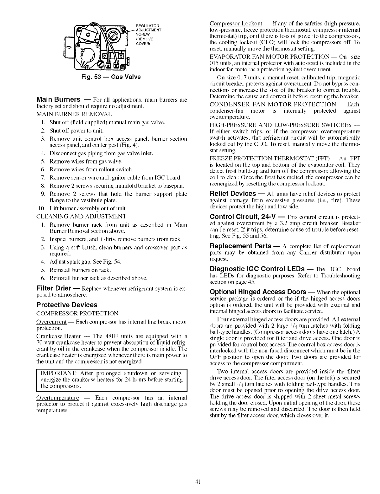
__ REGULATOR
/ADJUSTMENT
SCREW
(REMOVE
COVER)
Fig. 53 -- Gas Valve
Main Burners -- For all applications, m;fin burners are
facto Uset and should require no adjustment.
MAIN BURNER REMOVAL
1. Shut off (field-supplied) manual main gas v_dve.
2. Slmt off power to unit.
3. Remove unit control box access panel, burner section
access panel, and center post (Fig. 4).
4. Disconnect gas piping from gas valve inlet.
5. Remove wires from gas valve.
6. Remove wires from rollout switch.
7. Remove sensor wire and ignitor cable from [GC board.
8. Remove 2 screws securing manifold bracket to basepan.
9. Remove 2 screws that hold the burner support plate
flange to the vestibule plate.
10. Lift burner assembly out of unit.
CLEANING AND ADJUSTMENT
1. Remove burner rock from unit as described in Main
Burner Removal section above.
2. Inspect burners, and if dirty, remove burners fiom rack.
3. Using a soft brush, clean burners and crossover port as
requimd.
4. Adjust spark gap. See Fig. 54.
5. Reinst_dl burners on rack.
6. Reinstall burner rock as described above.
Filter Drier -- Replace whenever refiigerant system is ex-
posed to atmosphere.
Protective Devices
COMPRESSOR PROTECTION
Overcurmnt -- Each compressor has internal line break motor
protection.
Crankcase Heater -- The 48HJ units am equipped with a
70-wati crankcase heater to prevent absorption of liquid refi'ig-
erant by oil in the crankcase when the compressor is idle. The
crankcase heater is energized whenever them is main power to
the unit and the compressor is not energized.
IMPORTANT: After prolonged shutdown or servicing,
energize the crankcase heaters for 24 hours befom starting
the compmssors.
Overtemperature -- Each compressor has an internal
protector to protect it against excessively high discharge gas
temperatures.
Compressor Lockout -- If any of the safeties (high-pmssum,
low-pmssum, fmeze protection thermostat, compressor internal
therlllostat) trip, or if them is loss of power to the compressors,
the cooling lockout (CLO) will lock the compressors off. To
reset, manually move the thermostat setting.
EVAPORATOR FAN MOTOR PROTECTION -- On size
015 units, an internal protector with auto-reset is included in the
indoor fan motor as a protection against overcurrent.
On size 017 units, a manual reset, calibrated trip, magnetic
circuit bmaker protects against overcurrent. Do not bypass con-
nections or increase the size of the bmaker to cormct trouble.
Determine the cause and cormct it befom resetting the breakel:
CONDENSER-FAN MOTOR PROTECTION -- Each
condenser-fan motor is internally protected against
overtemperatum.
HIGH-PRESSURE AND LOW-PRESSURE SWITCHES --
If either switch trips, or if the compressor overtemperature
switch activates, that refrigerant circuit will be automatically
locked out by the CLO. To reset, manually move the thermo-
stat setting.
FREEZE PROTECTION THERMOSTAT (FPT) -- An FPT
is located on the top and bottom of the evaporator coil. They
detect frost build-up and turn off the compressol; allowing the
coil to clem: Once the frost has melted, the compressor can be
reenergized by resetting the compressor lockout.
Relief Devices -- All units have relief devices to protect
against damage from excessive pressures (i.e., tim). These
devices protect the high and low side.
Control Circuit, 24-V -- This control circuit is protect-
ed against overcurmnt by a 3.2 mnp circuit breakel: Bmaker
can be reset. If it trips, determine cause of trouble befom reset-
ting. See Fig. 55 and 56.
Replacement Parts -- A complete list of replacement
parts may be obtained from any Carrier distributor upon
request.
Diagnostic IGC Control LEDs-- The IGC bom'd
has LEDs for diagnostic purposes. Refer to Troubleshooting
section on page 45.
Optional Hinged Access Doors -- When the optional
service package is ordemd or the if the hinged access doors
option is ordemd, the unit will be provided with external and
internal hinged access doors to facilitate service.
Four external hinged access doors am provided. All external
dool_ me provided with 2 large 1/4 turn latches with folding
bail-type handles. (Compmssor access doors have one latch.) A
single door is provided for filter and drive access. One door is
provided for control box access. The control box access door is
interlocked with the non-fused disconnect which must be in the
OFF position to open the door Two doors tue provided for
access to the compressor compartment.
Two internal access doors am provided inside the filter/
diive access door. The filter access door (on the left) is secured
by 2 small 1/4 turn latches with folding bail-type handles. This
door must be opened prior to opening the drive access dool:
The drive access door is shipped with 2 sheet metal scmws
holding the door closed. Upon initial opening of the dool: these
scmws may be removed and discarded. The door is then held
shut by the filter access dool: which closes over it.
41
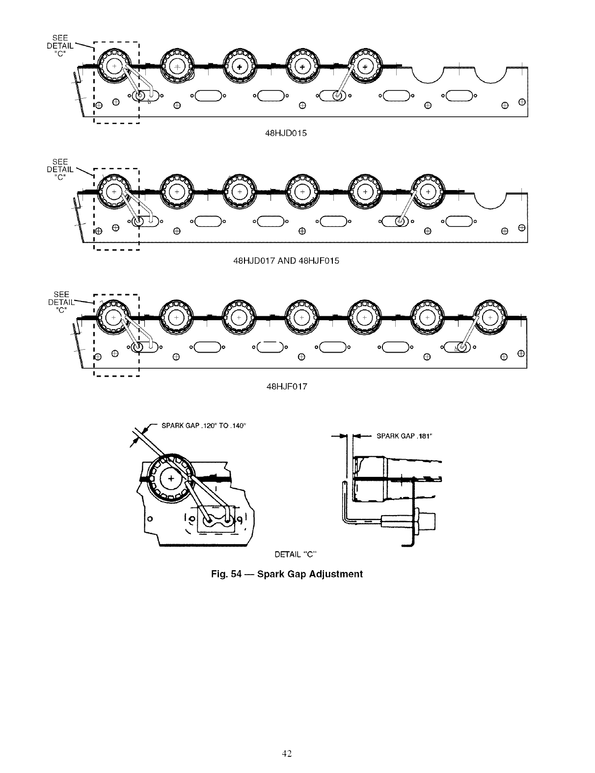
SEE
I
"C"
I
I
,@ •
I
I
Io
I
I
@ (9
48HJD015
@@ @
I
I
,@ @
I
I
48HJD017 AND 48HJ F015
@
I
I
I
oLZ.)o o0o o(: 3o
@
48HJF017
@@•
SPARK GAP .120" TO .140"
u
DETAIL "C"
Fig. 54 -- Spark Gap Adjustment
42
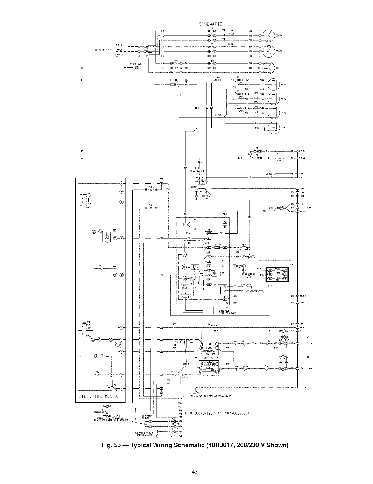
SCHEMATIC
cl
_E_ _ cz c_o_
S_PLY --sLu- _1 t_7_ _L_
_rca c
mm --YE L==_ YEt==_ _2_ _EL I_
--BLU_SL_ BLU
T| CAP yEL_ t_L OF_
C1 YEL_ _L Or_3
)eL_ CeZ ¢_I
('_ |
<s[[ lol_ sl
-- 0nN BL_
IELD THERMOSTAT _ _o_co,o._z_o_o_,_cc_s_o_,
u_ -- _ TO ECONOMIIER OPTIONIACCESSORY
Fig. 55 -- Typical Wiring Schematic (48HJ017, 208/230 V Shown)
43
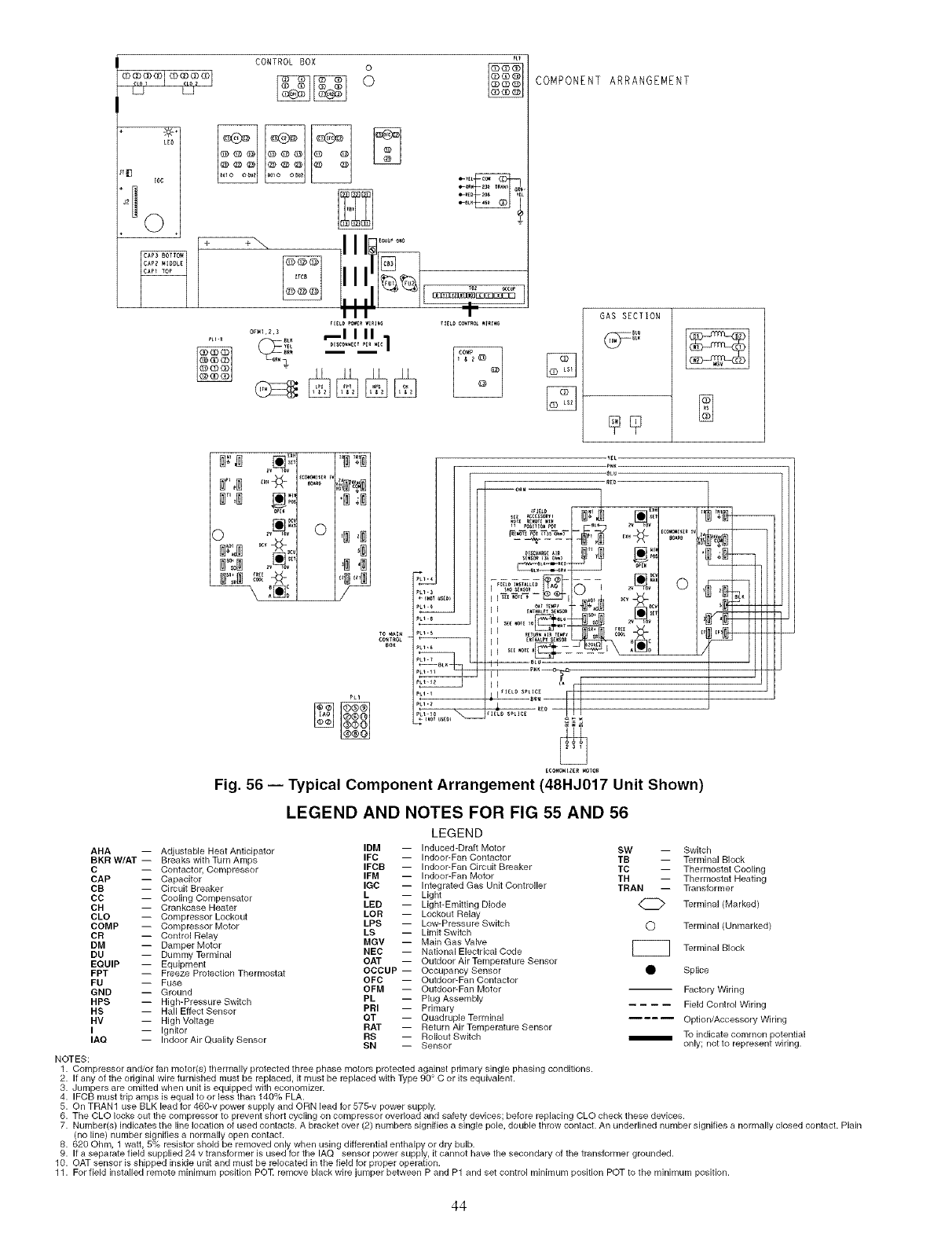
JH_ F
CONTROL BOX 0
oCOMPONENT ARRANGEMENT
[]
GAS SECTION
_LU
_LK
..... ©
*' 8"
,fill
L_
LHm
--ORN
, NNA [] 0
I _AOS_KS_R E _V _ov
L_
Fig. 56 -- Typical Component Arrangement (48HJ017 Unit Shown)
LEGEND AND NOTES FOR FIG 55 AND 56
LEGEND
AHA -- Adjustable Heat Anticipator IDM -- Induced-Draft Motor SW -- Switch
BKR W/AT -- Breaks with Turn Amps IFC -- Indoor-Fan Contactor TB -- Terminal Block
C -- Contactor, Compressor IFCB -- Indoor-Fan Circuit Breaker TC -- Thermostat Cooling
CAP -- Capacitor IFM -- Indoor-Fan Motor TH -- Thermostat Heating
CB -- Circuit Breaker IGC -- Integrated Gas Unit Controller TRAN -- Transformer
CC -- Cooling Compensator L-- Light
CH -- Crankcase Heater LED -- Light-Emitting Diode _ Terminal (Marked)
CLO -- Compressor Lockout LOR -- Lockout Relay
COMP -- Compressor Motor LPS -- Low=Pressure Switch O Terminal (Unmarked)
LS -- Limit Switch
CR -- Control Relay
DM -- Damper Motor MGV -- Main Gas Valve [[[[[[[_
DU -- Dummy Terminal NEC -- National Electrical Code Terminal Block
EQUIP -- Equipment OAT -- Outdoor Air Temperature Sensor
FPT -- Freeze Protection Thermostat OCCUP -- Occupancy Sensor _ Splice
OFC -- Outdoor-Fan Contactor
FU -- Fuse
GND -- Ground OFM -- Outdoor-Fan Motor Factory Wiring
HPS -- High-Pressure Switch PL -- Plug Assembly
HS -- Hall Effect Sensor PRI -- Primary Field Control Wiring
HV -- High Voltage QT -- Quadruple Terminal .... Option/Accessory Wiring
I -- Ignitor RAT -- Return Air Temperature Sensor
IAQ -- Indoor Air Quality Sensor RS -- Rollout Switch _ To indicate common potential
SN -- Sensor only; not to represent wiring.
NOTES:
1. Compressor and/or fan motor(s) thermally protected three phase motors protected against primary single phasing conditions.
2. If any of the original wire furnished must be replaced, it must be replaced with Type 90 ° C or its equivalent.
3. Jumpers are omitted when unit is equipped with economizer.
4. IFCB must trip amps is equal to or less than 140% FLA.
5. On TRAN1 use BLK lead for 460-v power supply and ORN lead for 575-v power supply.
6. The CLO locks out the compressor to prevent short cycling on compressor overload and safety devices; before replacing CLO check these devices.
7. Number(s) indicates the line location of used contacts. A bracket over (2) numbers signifies a single pole, double throw contact. An underlined number signifies a normally closed contact. Plain
(no line) number signifies a normally open contact.
8. 620 Ohm, 1 watt, 5% resistor shold be removed only when using differential enthalpy or dry bulb.
9. If a separate field supplied 24 v transformer is used for the IAQ sensor power supply, it cannot have the secondary of the transformer grounded.
10. OAT sensor is shipped inside unit and must be relocated in the field for proper operation.
11. For field installed remote ninimum position POT remove black wire jumper between P and P1 and set control minimum posRion POT to the minimum position.
44
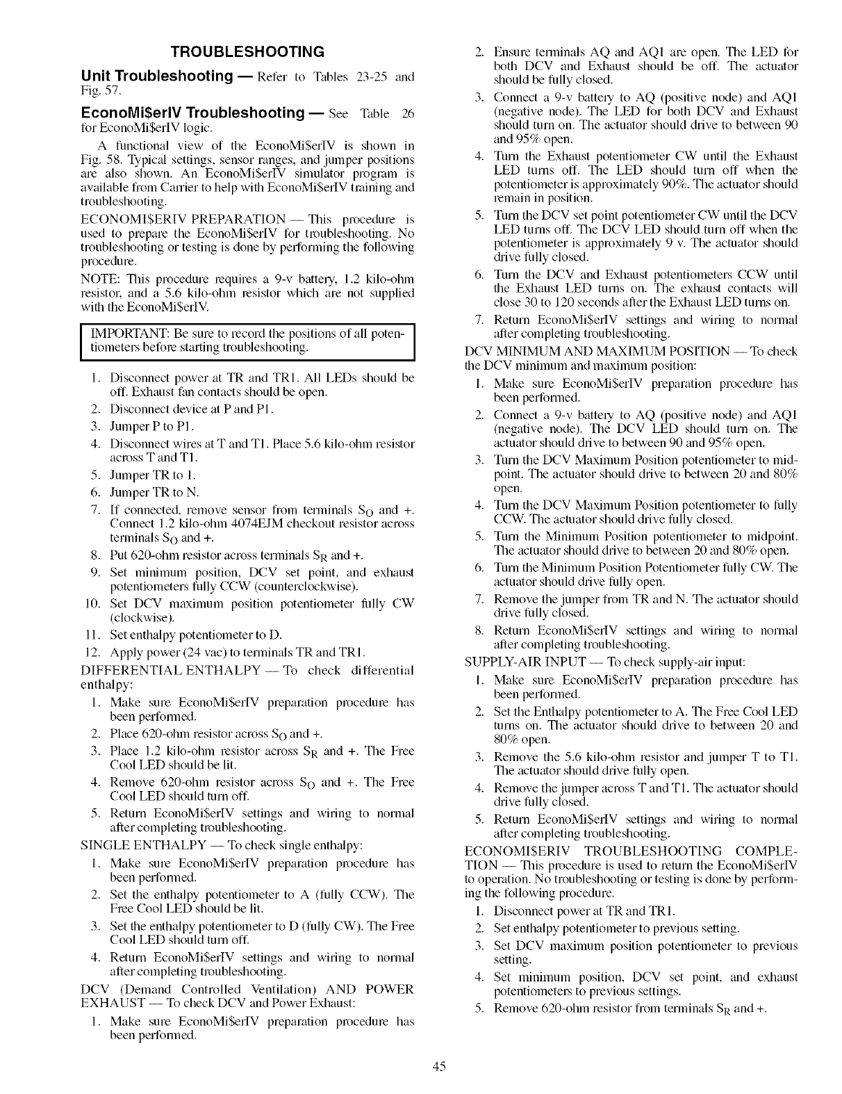
TROUBLESHOOTING
Unit Troubleshooting- Refer to Tables 23-25 and
Fig. 57.
EconoMi$erlV Troubleshooting-- See Table 26
for EconoMi$erlV logic.
A functional view of the EconoMiSerIV is shown in
Fig. 58. Typic;d settings, sensor ranges, and jumper positions
are also shown. An EconoMiSerIV simulator proglam is
available from Carrier to help with EconoMiSerIV tlaining and
troubleshooting.
ECONOMISERIV PREPARATION -- This procedure is
used to prepare the EconoMiSerlV for troubleshooting. No
troubleshooting or testing is done by performing the following
procedure.
NOTE: This procedure requires a 9-v battery. 1.2 kilo-ohln
resistol: and a 5.6 kilo-ohm resistor which are not supplied
with the EconoMiSerlV.
lMPORTANT: Be sure to record the positions of all poten-tiometers before starting troubleshooting.
1. Disconnect power at TR and TRI. All LEDs should be
off. Exhaust fan contacts should be open.
2. Disconnect device at P and PI.
3. Jumper P to PI.
4. Disconnect wires at T and TI. Place 5.6 kilo-ohm resistor
across T and TI.
5. Jumper TR to 1.
6. Jumper TR to N.
7. [f connected, remove sensor from terminals S o and +.
Connect 1.2 kilo-ohm 4074EJM checkout resistor across
terminals S o and +.
8. Put 620-ohm resistor across terminals SR and +.
9. Set minimum position, DCV set point, and exhaust
potentiometers fully CCW (counterclockwise).
10. Set DCV maximum position potentiometer lully CW
(clockwise).
11. Set enthalpy potentiometer to D.
12. Apply power (24 vac) to termimds TR and TRI.
DIFFERENTIAL ENTHALPY-- To check differential
enthalpy:
1. Make sure EconoMiSerlV preparation procedure has
been performed.
2. Place 620-ohm resistor across SO and +.
3. Place 1.2 kilo-ohln resistor across SR and +. The Free
Cool LED should be lit.
4. Remove 620-ohm resistor across S O and +. The Free
Cool LED should turn off.
5. Return EconoMiSerIV settings and wiring to normal
after completing troubleshooting.
SINGLE ENTHALPY -- To check single enth_dpy:
1. Make sure EconoMiSerIV preparation procedure has
been performed.
2. Set the enthalpy potentiometer to A (fully CCW). The
Flee Cool LED should be lit.
3. Set the enthalpy potentiometer to D (fully CW). The Free
Cool LED should turn off.
4. Return EconoMiSerIV settings and wiring to normal
after completing troubleshooting.
DCV (Demand Controlled Ventilation) AND POWER
EXHAUST -- To check DCV and Power Exhaust:
1. Make sure EconoMiSerIV preparation procedme has
been performed.
2. Ensure terminals AQ and AQI are open. The LED for
both DCV and Exhaust should be off. The actuator
should be fully closed.
3. Connect a 9-v batte qto AQ (positive node) and AQI
(negative node). The LED for both DCV and Exhaust
should turn on. The actuator should drive to between 90
and 95% open.
4. Turn the Exhaust potentiometer CW until the Exhaust
LED turns off. The LED should turn off when the
potentiometer is approximately 90%. The actuator should
remain in position.
5. Turn the DCV set point potentiometer CW until the DCV
LED turns off. The DCV LED should turn off when the
potentiometer is approximately 9 v. The actuator should
&ive fully closed.
6. Turn the DCV and Exhaust potentiometers CCW until
the Exhaust LED turns on. The exhaust contacts will
close 30 to 120 seconds after the Exhaust LED turns on.
7. Return EconoMiSerlV settings and wiring to norlnal
after completing troubleshooting.
DCV MINIMUM AND MAXIMUM POSITION -- To check
the DCV minimum and maximum position:
1. Make sure EconoMiSerIV preparation procedure has
been performed.
2. Connect a 9-v batte qto AQ (positive node) and AQI
(negative node). The DCV LED should turn on. The
actuator should drive to between 90 and 95% open.
3. Turn the DCV Maximum Position potentiometer to mid-
point. The actuator should drive to between 20 and 80%
open.
4. Turn the DCV Maximum Position potentiometer to fully
CCW. The actuator should drive fully closed.
5. Turn the Minimum Position potentiometer to midpoint.
The actuator should drive to between 20 and 80% open.
6. Turn the Minimum Position Potentiometer fully CW. The
actuator should drive fully open.
7. Remove the jumper from TR and N. The actuator should
c_hivefully closed.
8. Return EconoMiSerIV settings and wiring to normal
after completing troubleshooting.
SUPPLY-AIR INPUT -- To check supply-air input:
1. Make sure EconoMiSerIV preparation procedure has
been performed.
2. Set the Enthalpy potentiometer to A. The Free Cool LED
turns on. The actuator should drive to between 20 and
80% open.
3. Remove the 5.6 kilo-ohm resistor and jumper T to TI.
The actuator should drive fully open.
4. Remove the jumper across T and TI. The actuator should
(hive fully closed.
5. Return EconoMiSerIV settings and wiring to normal
after completing troubleshooting.
ECONOMISERIV TROUBLESHOOTING COMPLE-
TION -- This procedure is used to return the EconoMiSerlV
to operation. No troubleshooting or testing is done by perform-
ing the following procedure.
1. Disconnect power at TR and TRI.
2. Set enthalpy potentiometer to previous setting.
3. Set DCV maximum position potentiometer to previous
setting.
4. Set minimum position, DCV set point, and exhaust
potentiometel_ to previous settings.
5. Remove 620-ohm resistor from terminals SR and +.
45
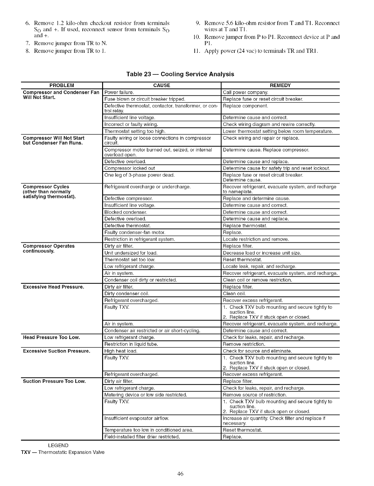
6. Remove1.2kilo-ohmcheckoutresistorfromterminals
SOand+.If used,reconnectsensorfromterminalsSO
and+.
7. RemovejumperfiomTRtoN.
8. RemovejumperfromTRto1.
9. Remove5.6kilo-ohmresistorfromTandTl.Reconnect
wilesatTandTI.
10.RemovejumperfromPtoPI.ReconnectdeviceatPand
PI.
11.Applypower(24vac)totermimdsTRandTRI.
Table 23 -- Cooling Service Analysis
PROBLEM
Compressor and Condenser Fan
Will Not Start.
Compressor Will Not Start
but Condenser Fan Runs.
Compressor Cycles
(other than normally
satisfying thermostat).
Compressor Operates
continuously.
Excessive Head Pressure.
Head Pressure Too Low.
Excessive Suction Pressure.
Suction Pressure Too Low.
CAUSE
Power failure.
Fuse blown or circuit breaker tripped.
Defective thermostat, contactor, transformer, or con-
trol relay.
Insufficient line voltage.
Incorrect or faulty wiring.
Thermostat setting too high.
Faulty wiring or loose connections in compressor
circuit.
Compressor motor burned out, seized, or internal
overload open.
Defective overload.
Compressor locked out
One leg of 3-phase power dead.
Refrigerant overcharge or undercharge.
Defective compressor.
Insufficient line voltage.
Blocked condenser.
Defective overload.
Defective thermostat.
Faulty condenser-fan motor.
Restriction in refrigerant system.
Dirty air filter.
Unit undersized for load.
Thermostat set too low.
Low refrigerant charge.
Air in system.
Condenser coil dirty or restricted.
Dirty air filter.
Dirty condenser coil.
Refrigerant overcharged.
Faulty TXV.
Air in system.
Condenser air restricted or air short-cycling.
Low refrigerant charge.
Restriction in liquid tube.
High heat load.
Faulty TXV.
Refrigerant overcharged.
Dirty air filter.
Low refrigerant charge.
Metering device or low side restricted.
Faulty TXV.
Insufficient evaporator airflow.
Temperature too low in conditioned area.
Field-installed filter drier restricted.
LEGEND
TXV -- Thermostatic Expansion Valve
REMEDY
Call power company.
Replace fuse or reset circuit breaker.
Replace component.
Determine cause and correct.
Check wiring diagram and rewire correctly.
Lower thermostat setting below room temperature.
Check wiring and repair or replace.
Determine cause. Replace compressor.
Determine cause and replace.
Determine cause for safety trip and reset lockout.
Replace fuse or reset circuit breaker.
Determine cause.
Recover refrigerant, evacuate system, and recharge
to nameplate.
Replace and determine cause.
Determine cause and correct.
Determine cause and correct.
Determine cause and replace.
Replace thermostat.
Replace.
Locate restriction and remove.
Replace filter.
Decrease load or increase unit size.
Reset thermostat.
Locate leak, repair, and recharge.
Recover refrigerant, evacuate system, and recharge.
Clean coil or remove restriction.
Replace filter.
Clean coil.
Recover excess refrigerant.
1. Check TXV bulb mounting and secure tightly to
suction line.
2. Replace TXV if stuck open or closed.
Recover refrigerant, evacuate system, and recharge.
Determine cause and correct.
Check for leaks, repair, and recharge.
Remove restriction.
Check for source and eliminate.
1. Check TXV bulb mounting and secure tightly to
suction line.
2. Replace TXV if stuck open or closed.
Recover excess refrigerant.
Replace filter.
Check for leaks, repair, and recharge.
Remove source of restriction.
1. Check TXV bulb mounting and secure tightly to
suction line.
2. Replace TXV if stuck open or closed.
Increase air quantity. Check filter and replace if
necessary.
Reset thermostat.
Replace.
46
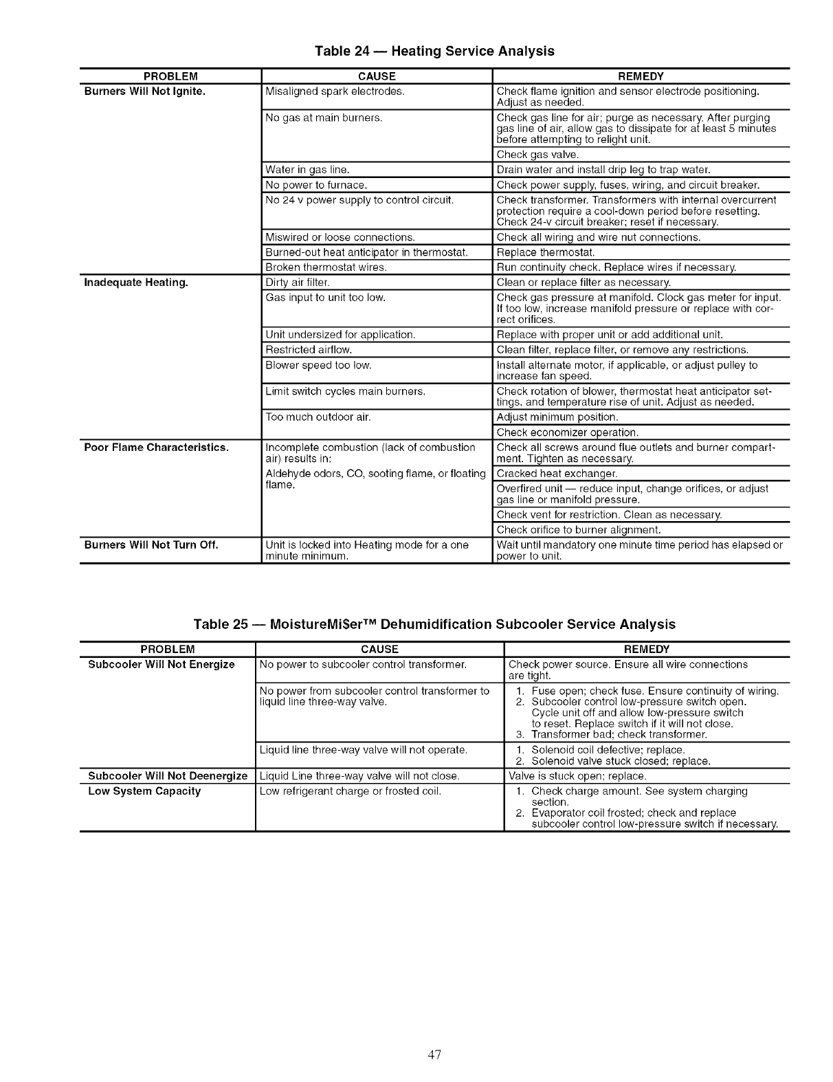
PROBLEM
Burners Will Not Ignite.
Inadequate Heating.
Poor Flame Characteristics.
Burners Will Not Turn Off.
Table 24 -- Heating Service Analysis
CAUSE
Misaligned spark electrodes.
No gas at main burners.
Water in gas line.
No power to furnace.
No 24 v power supply to control circuit.
Miswired or loose connections.
Burned-out heat anticipator in thermostat.
Broken thermostat wires.
Dirty air filter.
Gas input to unit too low.
Unit undersized for application.
Restricted airflow.
Blower speed too low.
Limit switch cycles main burners.
Too much outdoor air.
Incomplete combustion (lack of combustion
air) results in:
Aldehyde odors, CO, sooting flame, or floating
flame.
Unit is locked into Heating mode for a one
minute minimum.
REMEDY
Check flame ignition and sensor electrode positioning.
Adjust as needed.
Check gas line for air; purge as necessary. After purging
gas line of air, allow gas to dissipate for at least 5 minutes
before attempting to relight unit.
Check gas valve.
Drain water and install drip leg to trap water.
Check power supply, fuses, wiring, and circuit breaker.
Check transformer. Transformers with internal overcurrent
protection require a cool-down period before resetting.
Check 24-v circuit breaker; reset if necessary.
Check all wiring and wire nut connections.
Replace thermostat.
Run continuity check. Replace wires if necessary.
Clean or replace filter as necessary.
Check gas pressure at manifold. Clock gas meter for input.
If too low, increase manifold pressure or replace with cor-
rect orifices.
Replace with proper unit or add additional unit.
Clean filter, replace filter, or remove any restrictions.
Install alternate motor, if applicable, or adjust pulley to
increase fan speed.
Check rotation of blower, thermostat heat anticipator set-
tings, and temperature rise of unit. Adjust as needed.
Adjust minimum position.
Check economizer operation.
Check all screws around flue outlets and burner compart-
ment. Tighten as necessary.
Cracked heat exchanger.
Overtired unit -- reduce input, change orifices, or adjust
gas line or manifold pressure.
Check vent for restriction. Clean as necessary.
Check orifice to burner alignment.
Wait until mandatory one minute time period has elapsed or
power to unit.
Table 25 -- MoistureMi$er TM Dehumidification Subcooler Service Analysis
PROBLEM CAUSE REMEDY
Subcooler Will Not Energize No power to subcooler control transformer. Check power source. Ensure all wire connections
are tight.
No power from subcooler control transformer to 1. Fuse open; check fuse. Ensure continuity of wiring.
liquid line three-way valve. 2. Subcooler control low-pressure switch open.
Cycle unit off and allow low-pressure switch
to reset. Replace switch if it will not close.
3. Transformer bad; check transformer.
Liquid line three-way valve will not operate. 1. Solenoid coil defective; replace.
2. Solenoid valve stuck closed; replace.
Subcooler Will Not Deenergize Liquid Line three-way valve will not close. Valve is stuck open; replace.
Low System Capacity Low refrigerant charge or frosted coil. 1. Check charge amount. See system charging
section.
2. Evaporator coil frosted; check and replace
subcooler control low-pressure switch if necessary.
47
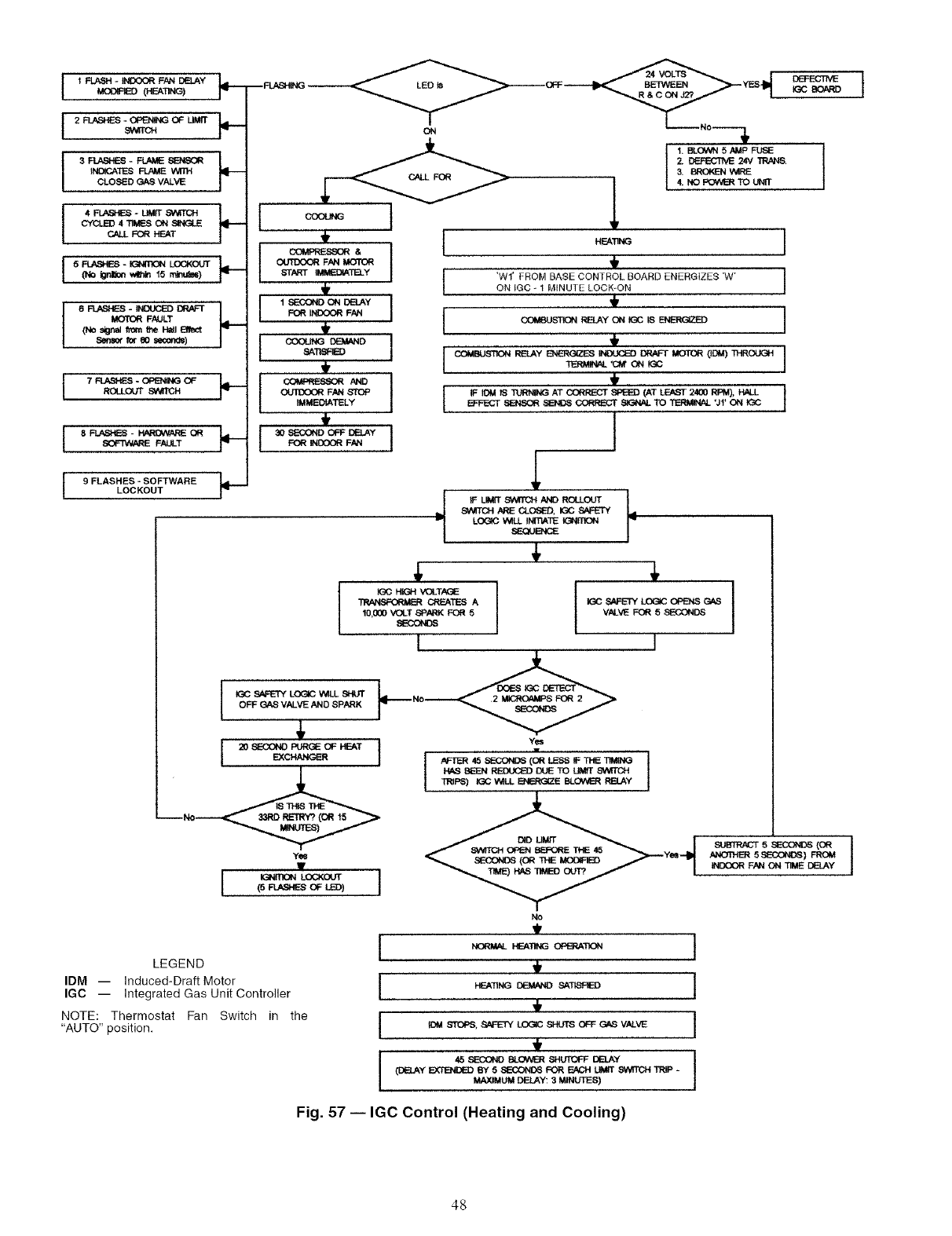
IFLASH-INDOORF_DEL_Y pI--MODFi_ (HEA'nNG)
I 2 FLASHES *OPENING OF UMfT
9NKCH
3 FLASHES -FLAME SENSOR
_NOICATES _ WITH
CLOSED GAS VALVE
4FLASHES - UME SWITCH
CYCLED 4TIMES ON SINGLE
CALL FOR HEAT
I 5 _ - IGNITK_NLOCKOUT(No i_r_,r_ _ 15 rn_)
6 R,ASi-ES- INDUCEDDR/_"r
MOTORFAULT
(No stgr_ from0-,eH=I Bfect
Senm,r fore0 seconds)
j7 P,J_,SHEe- OPENINGOF
J 8 FLASHES - _OR
SOFTWARE FALLT
J9FLASHES - SOFTWARE
LOCKOUT
I,I
COMPRESSOR & I
_1_ OUTG(X3_ FAN MOTOR
START IMMEDIATELY
_ FOR INDOOR FAN
•_TI_ ,
' _ ,
OUTOOOR FAN STOP
IMMEDIATELY
I
I
I
IGC s_ LOGIC V_ILL SI-_
OFF GAS VALVE AND SPARK
4,
Yes
(5 R.ASh_S OF LED)
J1. BLOWN 5 AMP FUSE
2. DEFECTNE 24V TR/_S.
3. BROKBq Vtt_E
4. NG POWE_ TO UNfT
I
'WI' FROM BASE CONTROL BOARD ENERGIZES 'W' J
ON IGC _ 1 M_NUTE LOCK*ON
COMBUST_N RELAY ON K_C BENERGIZE) I
,i,
_:FECT SENSOR SENDS CORRECT 81G,-_ALTO T_ UfON K_C
tF LIMfT8_M_CH AND ROLLOUT
SW_TCH ARE CLOSED, K_C SAFE3Y
LOGIC V_LL INITIATE tGN[fiON
SEQUENCE
4,
LEGEND
IDM -- Induced-Draft Motor
IGC -- Integrated Gas Unit Controller
NOTE: Thermostat Fan Switch in the
"AUTO" position.
K_C HIGH VOLTAG_
CREATES A
10,000 VOLT SPARK FOR 5
_LKX3NO_
I
Yes
No
t
I
I
I
I IGC 8#_ETY LOG_ OPENS C_*S
VALVE FOR 5 SECONDS
I
HEATING D_MAND SATISFIED
IDOl _T_, _ LOGIC SHUP_ OFF _VALVE
(D_y _ By 5S_COND_ F_ FJ_3H LIMIT SV_ TRIP -
MAXIMUM DELAY: 3 MINUTES)
t
t
I
I
!
SUBTRACT 5 SECONDS (OR |
ANOn-IE_ 5 SECONDS) FROM J
INDOOR FAN ON TIME DELAY
Fig. 57 -- IGC Control (Heating and Cooling)
48
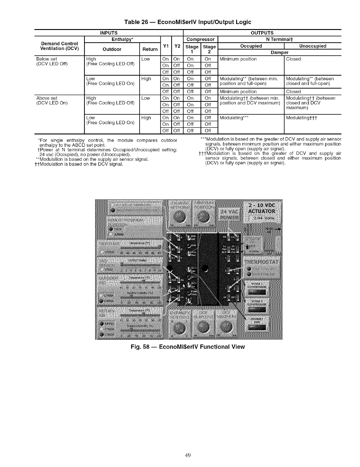
Table 26 -- EconoMi$erlV Input/Output Logic
Demand Control
Ventilation (DCV)
Below set
(DCV LED Off)
Above set
(DCV LED On)
INPUTS
Enthalpy* Compressor
Outdoor Return Y1 Y2 Stage Stage
1 2
High Low On On On On
(Free Cooling LED Off) On Off On Off
Off Off Off Off
Low High On On On Off
(Free Cooling LED On) On Off Off Off
Off Off Off Off
High Low On On On On
(Free Cooling LED Off) On Off On Off
Off Off Off Off
Low High On On On Off
(Free Cooling LED On) On Off Off Off
Off Off Off Off
*For single enthalpy
enthalpy to the ABCD
1-Power at N terminal determines Occupied/Unoccupied
24 vac (Occupied), no power (Unoccupied).
**Modulation is based on the supply air sensor signal.
ttModulation is based on the DCV signal.
OUTPUTS
N TerminaH-
Occupied Unoccupied
Damper
Minimum position Closed
Modulating** (between min.
3osition and full-open)
Minimum position
Modulatingl-t (between min.
3osition and DCV maximum)
Modulating***
Modulating** (between
closed and full-open)
Closed
Modulatingtl- (between
closed and DCV
maximum)
Modulatingl-l-t
control, the module compares outdoor
set point. setting:
***Modulation is based on the greater of DCV and supply air sensor
signals, between minimum position and either maximum position
(DCV) or fully open (supply air signal).
tttModulation is based on the greater of DCV and supply air
sensor signals, between closed and either maximum position
(DCV) or fully open (supply air signal).
Fig. 58 -- EconoMi$erlV Functional View
49
Altitude Compensation 8
Burner spark gap 42
Carrier Comfort Network® 12
Changeover set points 21, 23
Cha_ing chart, ret_igerant 40
Clearance 2, 5
CO 2 sensor
Configuration 24
Settings 23, 25
Combustion blower wheel 37
Compressor
Lockout 19, 41
Lubrication 38
Mounting 27
Rotation 27
Concentric duct 7
Condensate drain
Cleaning .;7
Location 8
Condenser coil 6
Cleaning 37
Condenser fan 6
Adjustment 40
Control circuit 41
Wiring 9
Convenience outlet 10
Crankcase heater 2Z 41
Demand ventilation control 24
Dehumidification 24
Dimensions 2, 3, 5
Ductwork 7
EconoMi$erIV 19-24
Control mode 21
Controller wiring 20
Damper nlovement 24
Demand ventilation control 24
Troubleshooting 45, 46, 49
Usage 21
Wiring 20
EconoMi$er2 19, 20
Electrical connections 9
Electrical data 11
Enthalpy changeover set points 23
Error codes 48
Evaporator coil 6
Cleaning .;7
Evaporator tim motor
Lubrication 3_,'
Motor data 34
Mounting 39
Perfornmnce 28-33
Pulley adjustment 38
Pulley setting 6, 34
Speed 6
Filter
Cleaning .;7
Size 6
Filter drier 41
Flue gas passageways .;7
Flue hood 7
Freeze protection thermostat 6, 41
Gas connection 6
Gas input 6
Gas piping 9
Gas pressure 9
Heat anticipator settings 9
High-pressure switch 6, 41
Hinged access doors 41
Horizontal adapter roof curb 2
Humidistat 25
Indoor airquality sensor 13
INDEX
Integrated gas controller
Error codes 48
Liquid propane 8
Low-pressure switch 6, 41
Main burners 37, 41
Manual outdoor air damper 10
MoistnreMiSer TM
Dehumidification 2.5,26, 40, 47
Motommsterg# I control 12, 13
Mounting
Compressor 27
Unit 2
Natural gas 6, 40
Non-fllsed disconnect O, 10
Operating sequence 35-37
Cooling 35-37
EconoMi$erlV .;5
EconoMi$er2 with
PremierLink control 35-37
Heating 35-37
Ontdoor air hood 11, 12
Outdoor air temperature sensor 13, 19
Outdoor air inlet screens
Cleaning 37
Dimensions 6
Physical data 6
Power supply O
Wiring 10
PmmierLink controls 12-17
Pressure, drop
Economizer .;4
MoistureMiSer 34
Pressure switches
High pressure 6
Low pressnre 6
Refrigerant
Charge 40
Type 6
Refrigerant service ports 27
Replacement parts 41
Return air filter 6, 27
Return air temperature sensor 22
Rigging unit 2, 4
Roof curb
Assembly 2
Dimensions 3
Leveling tolerances 2, 3
Weight 6
Safety considerations 1
Service 37-44
Start-up 27-37
Start-up checklist CL-l
Supply-air temperature sensor 13, 19
Thermostat 10
Troubleshooting 45-49
Weight
Corner 5
EconoMiSerIV .5,6
Maximnm 4
Unit .5,6
Wind baffle Z 12, 13
Wiring
EconoMiSerIV 20
EconoMiSer2 20
Humidistat 25
Non-filsed disconnect 10
Power connections 10
PremierLink 15
Thermostat 10
Unit 43, 44
5O
SERVICE TRAINING
Packaged Service Training programs are an excellent way to increase your knowledge of the equipment
discussed in this manual, including:
•Unit Fmnilituization
•Installation Overview
• Maintenance
• Operating Sequence
A large selection of product, theory, and skills programs are available, using popular video-based formats
and materi_ds. All include video and/or slides, plus companion book.
Classroom Service Training which includes '%rods-on" experience with the products in our labs can
mean increased confidence that really pays dividends in faster troubleshooting and fewer callbacks. Course
descriptions and schedules are in our catalog.
CALL FOR FREE CATALOG 1-800-644-5544
[ I Packaged Service Training [ I Classroom Service Training
51

Copyright 2006 Carrier Corporation
Manufacturer reserves the right to discontinue, or change at any time, specifications or designs without notice and without incurring obligations.
Catalog No. 04-53480010-01 Printed in U.S.A. Form 48HJ-30SI Pg 52 4-06 Replaces: 48HJ-26SI

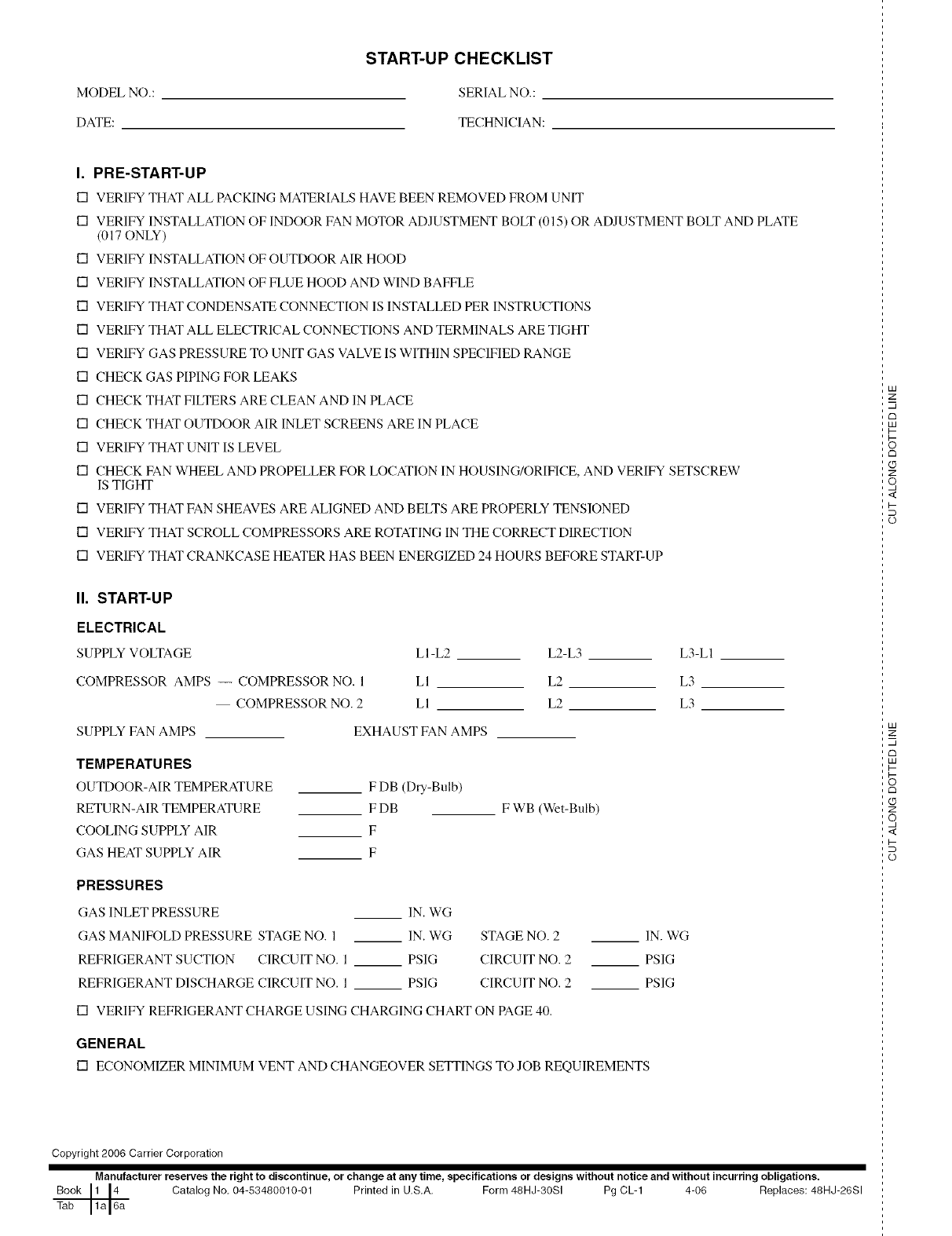
START-UP CHECKLIST
MODEL NO.: SERIAL NO.:
DATE: TECHNICIAN:
I. PRE-START-UP
[] VERIFY THAT ALL PACKING MATERIALS HAVE BEEN REMOVED FROM UNIT
[] VERIFY INSTALLATION OF INDOOR FAN MOTOR ADJUSTMENT BOLT (015) OR ADJUSTMENT BOLT AND PLATE
(017 ONLY)
[] VERIFY INSTALLATION OF OUTDOOR AIR HOOD
[] VERIFY INSTALLATION OF FLUE HOOD AND WIND BAFFLE
[] VERIFY THAT CONDENSATE CONNECTION IS INSTALLED PER INSTRUCTIONS
[] VERIFY THAT ALL ELECTRICAL CONNECTIONS AND TERMINALS ARE TIGHT
[] VERIFY GAS PRESSURE TO UNIT GAS VALVE IS WITHIN SPECIFIED RANGE
[] CHECK GAS PIPING FOR LEAKS
[] CHECK THAT FILTERS ARE CLEAN AND IN PLACE
[] CHECK THAT OUTDOOR AIR INLET SCREENS ARE IN PLACE
[] VERIFY THAT UNIT IS LEVEL
[] CHECK FAN WHEEL AND PROPELLER FOR LOCATION IN HOUSING/ORIFICE, AND VERIFY SETSCREW
IS TIGHT
[] VERIFY THAT FAN SHEAVES ARE ALIGNED AND BELTS ARE PROPERLY TENSIONED
[] VERIFY THAT SCROLL COMPRESSORS ARE ROTATING IN THE CORRECT DIRECTION
[] VERIFY THAT CRANKCASE HEATER HAS BEEN ENERGIZED 24 HOURS BEFORE START-UP
II. START-UP
ELECTRICAL
SUPPLY VOLTAGE LI-L2
COMPRESSOR AMPS -- COMPRESSOR NO. 1 LI
COMPRESSOR NO. 2 LI
L2-L3 L3-LI
L2 L3
L2 L3
SUPPLY FAN AMPS
TEMPERATURES
OUTDOOR-AIR TEMPERATURE
RETURN-AIR TEMPERATURE
COOLING SUPPLY AIR
GAS HEAT SUPPLY AIR
PRESSURES
(;AS INLET PRESSURE
EXHAUST FAN AMPS
F DB (Dry-Bulb)
FDB
F
F
F WB (Wet-Bulb)
IN. WG
GAS MANIFOLf) PRESSURE STAGE NO. 1 IN. WG STAGE NO. 2
REFRIGERANT SUCTION CIRCUIT NO. 1 PSIG CIRCUIT NO. 2
REFRIGERANT DISCHARGE CIRCUIT NO. 1 PSIG CIRCUIT NO. 2
[] VERIFY REFRIGERANT CHARGE USING CHARGING CHART ON PAGE 40.
GENERAL
[] ECONOMIZER MINIMUM VENT AND CHANGEOVER SETFINGS TO JOB REQUIREMENTS
IN. WG
PSIG
PSIG
Copyright 2006 Carrier Corporation
Manufacturer reserves the right to discontinue, or change at any time, specifications or designs without notice and without incurring obligations.
Book 1 [4 Catalog No, 04-53480010-01 Printed in U.S,A, Form 48HJ-30SI Pg CL-1 4-06 Replaces: 48HJ-26SI
Tab 1a 16a
LU
2:
C3
LU
I--
rm
Z
o,
,<
I-
o
LU
2:
rm
LU
I--
C3
Z
o,
,<
o
