CARRIER Package Units(both Units Combined) Manual L0606344
User Manual: CARRIER CARRIER Package Units(both units combined) Manual CARRIER Package Units(both units combined) Owner's Manual, CARRIER Package Units(both units combined) installation guides
Open the PDF directly: View PDF ![]() .
.
Page Count: 48
50HJ015,017
Single-Package Rooftop Units
Electric Cooling with Electric Heat Option
Installation, Start-Up and
Service Instructions
CONTENTS
Page
SAFETY CONSIDERATIONS ...................... 1
INSTALLATION ................................ 1-27
Step 1 -- Provide Unit Support ................... 1
•ROOF CURB
• ALTERNATE UNIT SUPPORT
Step 2 -- Rig and Place Unit ..................... 4
•POSITIONING
• ROOF MOUNT
Step 3-- Field Fabricate Ductwork ............... 4
Step 4 -- Make Unit Duct Connections ........... 7
Step 5 -- Trap Condensate Drain ................. 7
Step 6 -- Make Electrical Connections ........... 8
• FIELD POWER SUPPLY
• FIELD CONTROL WIRING
• OPTIONAL NON-FUSED DISCONNECT
• OPTIONAL CONVENIENCE OUTLET
Step 7-- Make Outdoor-Air Inlet
Adjustments .................................... 10
• MANUAL OUTDOOR-AIR DAMPER
Step 8-- Install Outdoor-Air Hood .............. 10
Step 9 -- Install All Accessories ................. 11
• MOTORMASTER® I CONTROL INSTALLATION
Step 10 -- Adjust Factory-Installed Options ..... 12
• PREMIERLINK TM CONTROL
• ENTHALPY SWITCH/RECEIVER
• OUTDOOR ENTHALPY CONTROL
• DIFFERENTIAL ENTHALPY CONTROL
• ENTHALPY SENSORS AND CONTROL
• OPTIONAL ECONOMISERIV AND ECONOMISER2
• ECONOMISERIV STANDARD SENSORS
• ECONOMISERIV CONTROL MODES
Step 11 -- Install Humidistat for
Optional MoistureMi$er TM Package ............ 25
START-UP ....................................... 28-34
Unit Preparation ................................. 28
Operating Sequence ............................ 33
SERVICE ........................................ 35-40
TROUBLESHOOTING ........................... 41-44
INDEX .............................................. 45
START-UP CHECKLIST ......................... CL-1
SAFETY CONSIDERATIONS
Installation and selwicing of air-conditioning equipment can
be hazardous due to system pressure and electric_d compo-
nents. Only trained and qualified service personnel should in-
stall, repaiL or service ai>conditioning equipment.
Untrained personnel can perform basic maintenance func-
tions of cleaning coils and filters and replacing filters. All other
operations should be performed by trained service personnel.
When working on air-conditioning equipment, observe
precautions in the literature, tags and labels attached to the unit,
and other safety precautions that may apply.
Follow all safety codes. Wear safety glasses and work
gloves. Use quenching cloth for unbrazing operations. Have
fire extinguishers available for _dl brazing operations.
Before performing service or maintenance operations on
unit, turn off main power switch to unit. Electrical shock
could cause personal injury.
IMPORTANT: Units have high mnbient temperature oper- ]
ating limits. If limits are exceeded, the unit will automati- I
cally lock the compressor out of operation. Manual reset
will be required to restart the compressor:
INSTALLATION
Inspect unit for transportation &unage. If damage is found,
file claim with transportation agency.
Step 1 -- Provide Unit Support
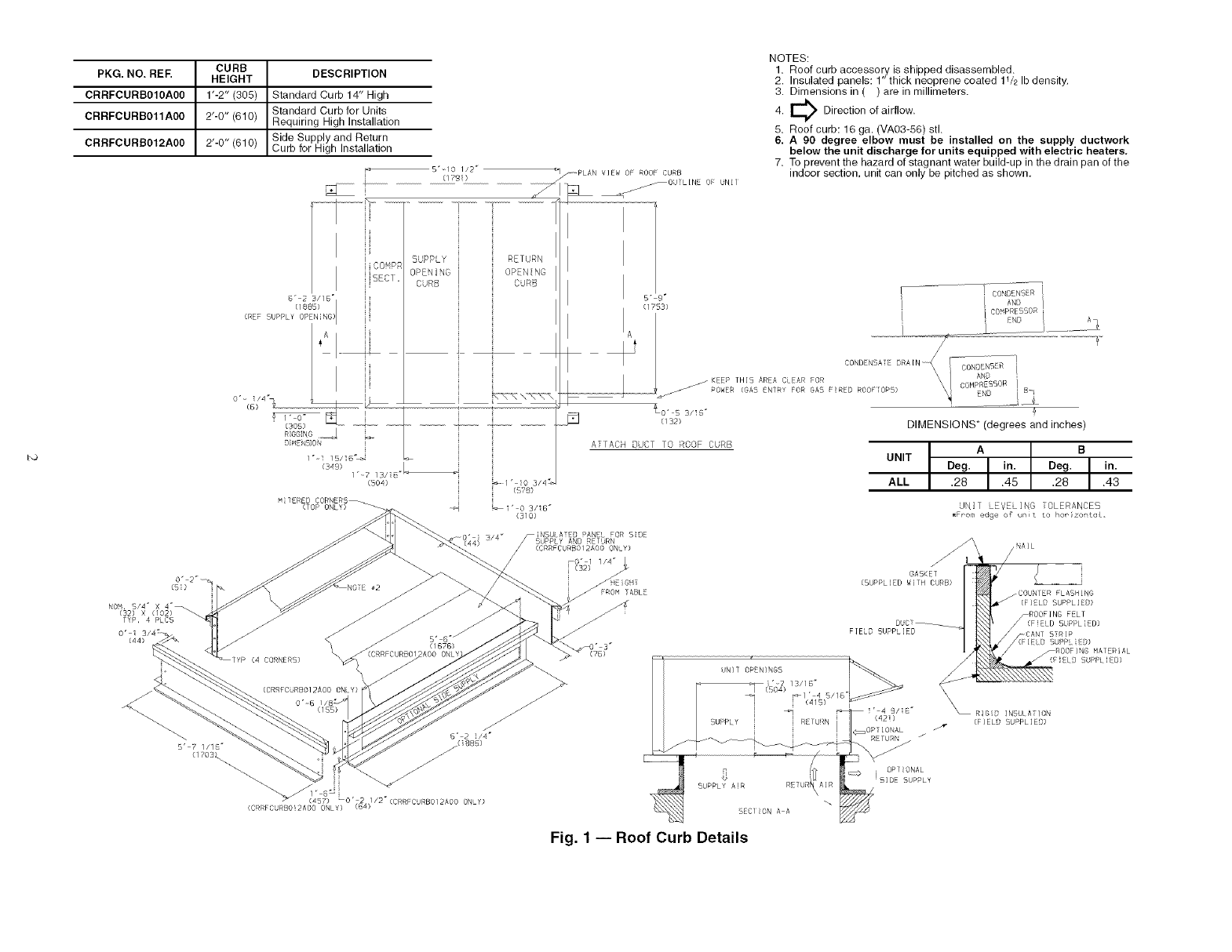
ROOF CURB -- Asselnble and install accessory roof curb or
horizontal supply roof curb in accordance with instructions
shipped with the accesso q. Accesso Uroof curb and horizontal
supply roof curb and information required to field fabricate a
roof curb or horizont_dsupply roof curb gueshown in Fig. 1 and
2. Install insulation, cant strips, roofing, and counter flashing as
shown. Ductwork can be secured to roof curb before unit is set
in place.
IMPORTANT: The gasketing of the unit to the roof curb or
horizontal supply roof curb is critical for a leakproof se_d.
Install gasket supplied with the roof curb or horizont_d sup-
ply roof curb as shown in Fig, 1. hnproperly applied gasket
can result in air leaks and poor unit performance.
Roof curb must be level. This is necessary to permit unit
drain to function properly. Unit leveling tolerance is + ]/]_ in.
per linear ft in any direction. Refer to Accessory Roof Curb or
Horizontal Supply Roof Curb Installation Instructions for addi-
tional information as required.
ALTERNATE UNIT SUPPORT -- When the curb or a&tpter
cannot be used, support unit with sleepel_ using unit curb or
adapter support area. [f sleepers cannot be used, support long
sides of unit with a minimum of 3 equally spaced 4-in. x 4-in.
pads on each side.
Manufacturer reserves the right to discontinue, or change at any time, specifications or designs without notice and without incurring obligations.
Catalog No. 04-53500012-01 Printed in U.S.A. Form 50HJ-29SI Pg 1 3-06 Replaces: 50HJ-25SI
CURB
PKG.NO. REF. HEIGHT
CRRFCURBO10A00 1"-2" (305)
CRRFCURB011A00 2"-0" (610)
CRRFCURB012A00 2'-0" (610)
DESCRIPTION
Standard Curb 14" High
Standard Curb for Units
Requiring High Installation
Side Supply and Return
Curb for H gh neta aton
CO'_P_
BC1.
B" 2B//B °
UPPLY" rS'Nd
(/rD!)
SUPPLY RETURN
OPENING
CURB
(349) L
1"-7 13/i8 "_
(BOA)
MITERED CORNERS_
(T5P ONLY)
/PLAN VIEW 5F ROOF CURB
jOUTL[NE OF UNIT
NOTES:
1. Roof curb accessory is shipped disassembled.
2. Insulated panels: 1" thick neoprene coated 11/2 Ib density.
3. Dimensions in ( ) are in millimeters.
E_ Direction of airflow.
4.
5. Roof curb: 16 ga. (VA03-56) stl.
6. A 90 degree elbow must be installed on the supply ductwork
below the unit discharge for units equipped with electric heaters.
7. To prevent the hazard of stagnant water build-up in the drain pan of the
indoor section, unit can only be pitched as shown.
5" r i CONSS'R i
I I"'l B' co PRE
EN /
A ........
t ! C5ND NSA RA[N_ CONOENB R
dEEP TH]5 ARA CL AR FOR AN
POWER (GAS _NTRY FOR GAB :RED ROOF 0#'5) COH_._5_R B
J:_ (s2> DIMENSIONS* (degrees and inches)
ATTACH DUCT TO ROOF CURB
UNIT
ALL
Deg. A in. Deg. B in.
.28 .45 .28 .43
UNI1 LEVELING OLERANCES
• Fr-ora edge o_ n t to ho_ zo:,toL,
TYP, 4 PLC5
0'i
0"_6
B" 2 !14"
5' 7 //1 _-" /(BBB)
{170B_ -/"
1" 8" .
457 LO' .2/: / /2 (CRRFC RB0/2AO0 ON Y}
(CR C RBO!2AOO ONLY) {B_)
_0" 1 1/4"
(32) GA5KET
(SUPPLIED WITH CURB)
FIELD 5UPPL[EB
_COUNTER FLASHING
(FIELD SUPPLIED)
CANT STRIP
_ilELD SUPPLIED)
_ROOFING MATERIAL
/(FIELD SUPPLIED)
\\\RIGID INBULATION
(FIELD SUPPLIED)
Fig. 1 -- Roof Curb Details
25% VENT AIR//
ECONOMIZER
HOOD _.
AIR
OUT
HORIZONTALSUPPLY _
CURB (CRRFCURB013A00)
I
i
I
E
f//
\
TRANSITION DUCT
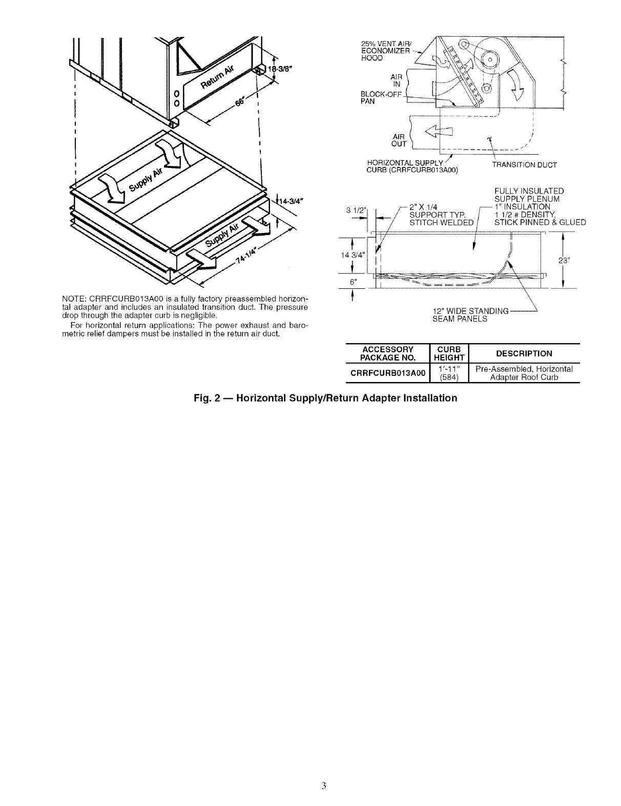
NOTE: CRRFCURB013A00 is a fully factory preassembled horizon-
tal adapter and includes an insulated transition duct. The pressure
drop through the adapter curb is negligible.
For horizontal return applications: The power exhaust and baro-
metric relief dampers must be installed in the return air duct.
T
14 3/4"
6"
FULLY INSULATED
SUPPLY PLENUM
/_ 2"X 1/4 f_ 1" INSULATION
/SUPPORT TYR /1 1/2 # DENSITY,
/STITCH WELDED/STICK PINNED & GLUED
_-_ 12,,W __-_-___ "P'21_3
SEAM PANELS
ACCESSORY CURB
PACKAGE NO. HEIGHT DESCRIPTION
1'-1 1" Pre-Assembled, Horizontal
CRRFCURB013A00 (584 Adapter Roof Curb
Fig. 2 -- Horizontal Supply/Return Adapter Installation

Step 2 -- Rig and Place Unit -- Keep unit upright,
and do not &op. Use spreader bal_ over unit to prevent sling or
cable &image. Rollers may be used to move unit across a roof.
Level by using unit frame as a reference; leveling tolerance is
_+1/16in. per line;u" fl in any direction. See Fig. 3 for additional
information. Unit weight is shown in Table 1.
Four liming holes ale provided in ends of unit base r;fils as
shown in Fig. 3. Refer to rigging instructions on unit.
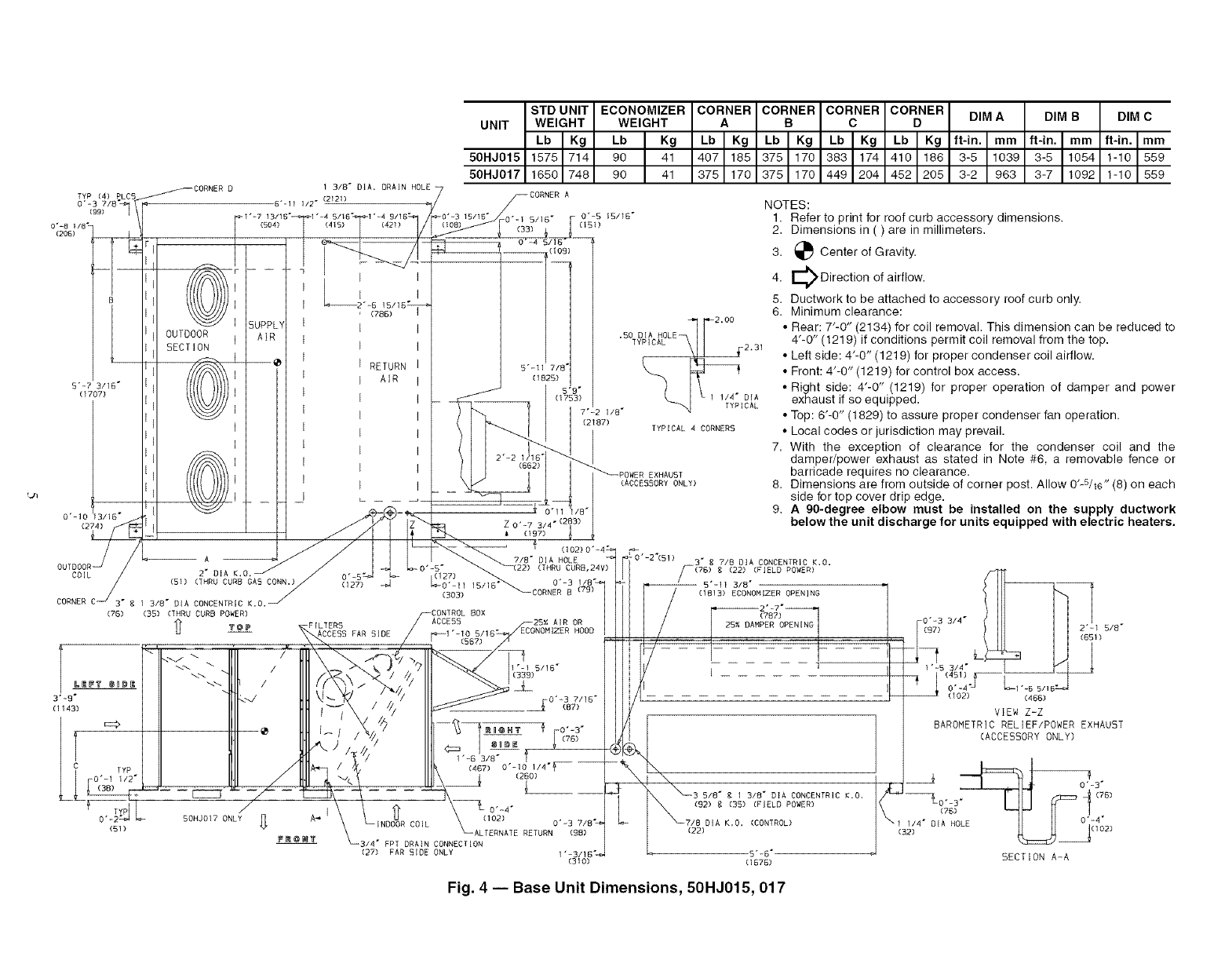
POSITIONING -- Provide clearance around and above unit
for airflow, safety, and service access (Fig. 4).
Do not install unit in an indoor location. Do not locate ;dr
inlets near exhaust vents or other sources of contaminated ail_
Although unit is weatherproof, guard against water fiom
higher level runoff and overhangs.
ROOF MOUNT -- Check building codes for weight distribu-
tion requirements.
Step 3 -- Field Fabricate Ductwork -- Secure _dl
ducts to building structure. Use flexible duct connectors be-
tween unit and ducts as required. Insulate and weatherproof all
external ductwork, joints, and roof openings with counter
flashing and mastic in accordance with applicable codes.
Ducts passing through an unconditioned space must be in-
sulated and covered with a vapor barriel:
The 50HJ units with electric heat require a l-in. clearance
for the that 24 in. of ductwork.
Outlet grilles must not lie directly below unit discharge.
NOTE: A 90-degree elbow must be provided in the ductwoN
to comply with UL (Underwritel_ Laboratories) codes for use
with electric heat.
SEE
"DETAIL
10'-0"
(3048)
"DETAILA"
RIGGINGHOOK
3'-71/2"
(t 105)
UNITBASERAIL
MAXIMUM DIMENSIONS
UNIT SHIPPING WEIGHT A B
50HJ Ib ] kg ft-in. ] mm ft-in, mm
015 1625 I737 6-11V2 I2121 4-0 1219
017 1700 771 6-11V2 2121 3-10 1168
NOTES:
1. Dimensions in ( ) are in millimeters.
2. Refer to Table 1 for unit operating weights,
3. Remove boards at ends of unit and runners prior to rigging.
4. Rig by inserting hooks into unit base rails as shown, Use corner
post from packaging to protect coil from damage. Use bumper
boards for spreader bars,
5. Weights do not include optional economizer. Add 90 Ib (41 kg)
for economizer weight.
6. Weights given are for aluminum evaporator and condenser coil
plate fins, Weights include electric heat.
7. Add 75 Ib (34 kg) for crating on 50HJ015 and 017 units,
8. Add 150 Ib (68 kg) for copper condenser coil, Add 280 Ib
(127 kg) for copper condenser and evaporator coils.
For vertical supply and return units, tools or parts could
drop into ductwork and cause an injury. Install a 90-degree
turn in the return ductwork between the unit and the condi-
tioned space. If a 90-degree elbow cannot be installed, then
a grille of sufficient strength and density should be inst_dled
to prevent objects from falling into the conditioned space.
Due to electric heatel: supply duct will requile 90-degree
elbow.
All panels must be in place when rigging.
Fig. 3 -- Rigging Details
TYP (4) P,LC5 _CORNE8 D
o-&p _1!
0"-8 I/B _
(206)
B
[
5"-7 3/16"
(1707)
OUTDOOR
SECTION
1 3/8" DIA. DRAIN HOLE
6"-11 1/2" (2121)
_1"=7 13115" 1"-4 5/15 _ 1'=4 9115"
I
i
i
i
i
i
i
SUPP[
Am
i
i
i
i
i
i
i
i
i
i
i
i
i
i
i
i
i
i
i
i
i
i
i
i
i
i
(788)
RETURN
AIR
STD UNIT ECONOMIZER
UNIT WEIGHT WEIGHT
Lb IKg Lb IKg
50HJ015 1575 714 90 41
50HJ017 1650 748 90 41
7_CORNER A
_0"=3 15/16" -i" 0"-5 15/15"
(108) 0 (33)5 6 (151)
5"-11 7/E
(1825)
CO.#ERCO%NERCO.oN.CO%NER
•bIKgI,bI KgI,bI*gI,b I*g
4o7165137511701383117414101186
375 170 375 170 449 204 452 205
•50 DIA HOLE ['-12'00
TYPICAL__I 231
_; 1 1/4" DIA
7"-2 1/8" [CAL
(2187) TYPICAL 4 CORNERS
_\_/, L _ _
0._ 03/18- i z0._731 -,2
(_L_L L:- --- _ /I I I_S-. , (157)
//
/L__ _ .
_.A K._, "_ 1,_ O'- 27 22) (THRU CURB,24V)
(s..NRUCUR_O*SCONN.)/ °0) _ Z#S ..... _ o.-3i,8,
COR_ERC 13,_-DIACONCENTRIC_,o._ '_ 50_;is,18_OORRERB(_B)
(35) (THRU CURB POWER)
FILTERS
ACCESS FAR SIDE
.) ?
// - / ///
A_ CO]L
BOX
ACCE55 25_; AIR OR
_I "-10 5118" ECONOMIZER HOOD
(567)
1"-6 3/8" 1
-314" FPT DRAIN CONNECTION
(27) FAR SIDE ONLY 1"-3/18"_"
(310)
(76)
3"-9"
(1143)
(51)
EXHAU5T
(ACCESSORY ONLY)
50HJ017 ONLY
DIM A
ft-in. I mm
3-5 1039
3-2 963
DIM BDIM C
ft-in. Im m I ft-in. Imm
3-5 1054 I1-1o 1559
3-7 1092 1-10 559
NOTES:
1. Refer to print for roof curb accessory dimensions.
2. Dimensions in ( ) are in millimeters.
3. _ Center of Gravity.
E_ Direction of airflow.
4.
5. Ductwork to be attached to accessory roof curb only.
6. Minimum clearance:
• Rear: 7"-0" (2134) for coil removal. This dimension can be reduced to
4'-0" (1219) if conditions permit coil removal from the top.
• Left side: 4"-0" (1219) for proper condenser coil airflow.
• Front: 4'-0" (1219) for control box access.
• Right side: 4"-0" (1219) for proper operation of damper and power
exhaust if so equipped•
• Top: 6'@" (1829) to assure proper condenser fan operation•
• Local codes or jurisdiction may prevail•
7. With the exception of clearance for the condenser coil and the
damper/power exhaust as stated in Note #6, a removable fence or
barricade requires no clearance.
8. Dimensions are from outside of corner post. Allow O'-S/m" (8) on each
side for top cover drip edge.
9. A 90-degree elbow must be installed on the supply ductwork
below the unit discharge for units equipped with electric heaters.
0"-2"(51) 3" g 718 DIA CONCENTRIC K.O.
r-(7B) g (22) (FIELD ROWER)
-- 5"-11 3/8"
(1813) ECONOMIZER OPENING
(?B?)
PER OPEN[NG
/---1 "1
['_LJ0:oSL'S:)'°:::F--
VIEW Z=Z
BAROMETRICRELIEF/POWEREXHAUST
(ACCESSORYONLY)
t0"qf3"
. _3 5,B',13,8-o. CO.OENTRIO_0 _1;_ (7B)
(92) g (35) (FIELD POWER) *"
0"-4"
7/8 DIA K,O. (CONTROL) _1(31_4" D A HO
(22) LE _ 1(102)
5"-6" _ SECTION A-A
(1576)
Fig. 4 -- Base Unit Dimensions, 50HJ015, 017
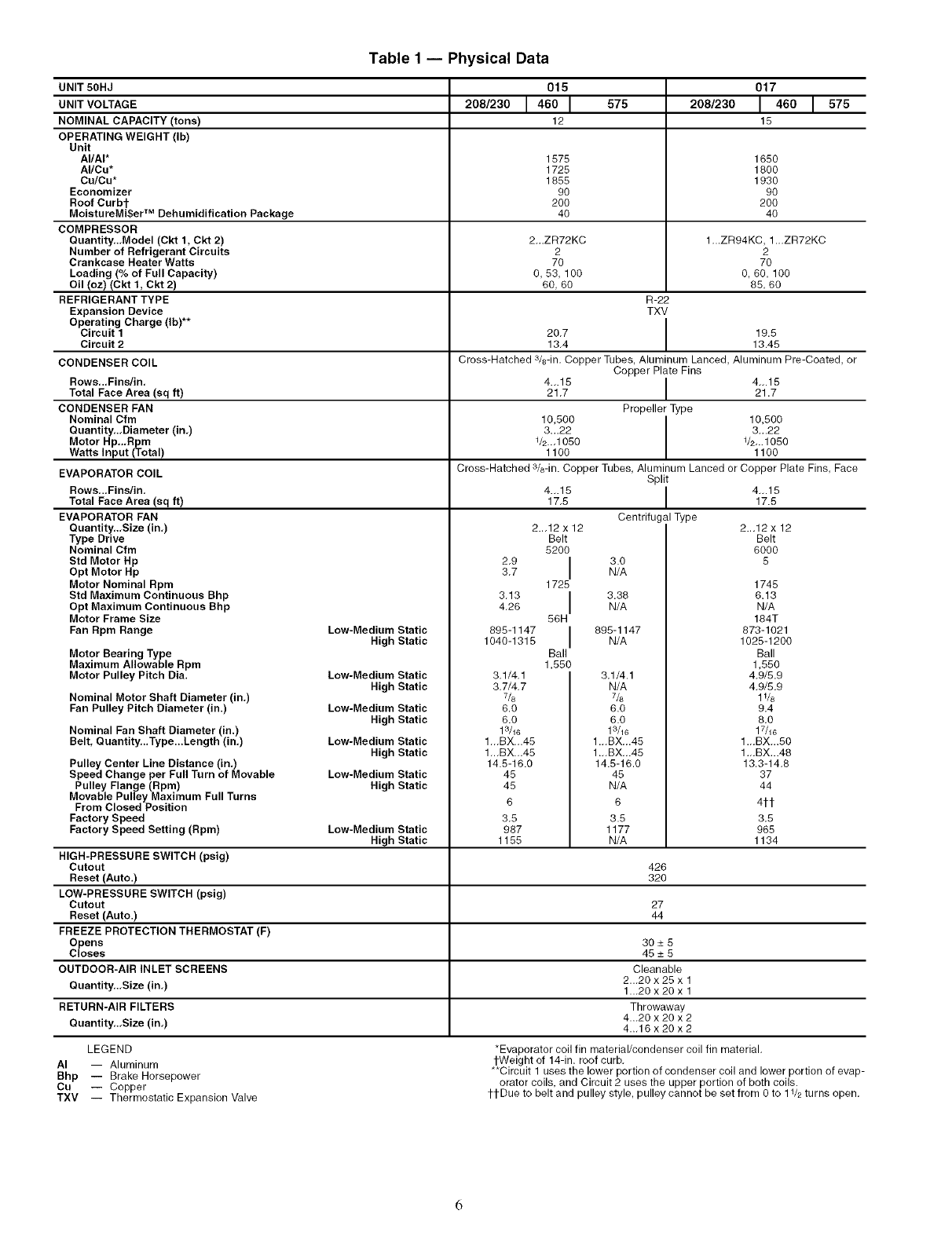
Table1 -- Physical Data
UNIT 50HJ
UNIT VOLTAGE
NOMINAL CAPACITY (tons)
OPERATING WEIGHT (Ib)
Unit
AI/AI*
AI/Cu*
Cu/Cu*
Economizer
Roof Curbt
MoistureMi$er TM Dehumidification Package
COMPRESSOR
Quantity,.,Model (Ckt 1, Ckt 2)
Number of Refrigerant Circuits
Crankcase Heater Watts
Loading (% of Full Capacity)
Oil (oz) (Ckt t, Ckt 2)
REFRIGERANT TYPE
Expansion Device
Operating Charge (Ib)**
Circuit 1
Circuit 2
575 208/230
1575 1650
1725 1800
1855 1930
90 90
200 200
40 40
2-.ZR72KC 1-.ZR94KC, 1-.ZR72KC
2 2
70 70
0,53, 100 O,60, 100
60, 60 85, 60
R-22
TXV
20.7 I 19.5
13.4 13.45
015
208/230 1460 I
12
017
146o1575
15
CONDENSER COIL Cross-Hatched a/s-in. Copper Tubes, Aluminum Lanced, Aluminum Pre-Coated, or
Copper Plate Fins
Rows,..Fins/in, 4...15 I 4_.15
Total Face Area (sq ft) 21.7 I 21.7
CONDENSER FAN Propeller Type
Nominal Cfm 10,500 I 10,500
Quantity,.,Diameter (in,) 3...22 I 3_.22
Motor Hp..,Rpm 1/2._1050 V2-.1050
Watts Input (Total) 1100 1100
Cross-Hatched 3/8-in. Copper Tubes, Aluminum Lanced or Copper Plate Fins, Face
Split
4...15 I 4...15
17.5 17.5
Centrifugal Type
EVAPORATOR COIL
Rows,..Finslin,
Total Face Area (sq ft)
EVAPORATOR FAN
Quantity,.,Size (in,)
Type Drive
Nominal Cfm
Std Motor Hp
Opt Motor Hp
Motor Nominal Rpm
Std Maximum Continuous Bhp
Opt Maximum Continuous Bhp
Motor Frame Size
Fan Rpm Range
Motor Bearing Type
Maximum Allowable Rpm
Motor Pulley Pitch Dia.
Nominal Motor Shaft Diameter (in.)
Fan Pulley Pitch Diameter (in.)
Low-Medium Static
High Static
Low-Medium Static
High Static
Low=Medium Static
High Static
Low-Medium Static
High Static
Low-Medium Static
High Static
Nominal Fan Shaft Diameter (in.)
Belt, Quantity,..Type...Length (in.)
Pulley Center Line Distance (in,)
Speed Change per Full Turn of Movable
Pulley Flange (Rpm)
Movable Pulley Maximum Full Turns
From Closed Position
Factory Speed
Factory Speed Setting (Rpm)
2.9
3.7
3.13
4.26
895-1147
1040-1315
2.-12 x 12
Belt
5200 I
1725 I
56H I
Ball
1,550
3.1/4.1
3.7/4.7
7&
6.0
6.0
13/16
1-.BX.-45
1-.BX.-45
14.5-16.0
45
45
6
3.5
987
1155
3.0
N/A
3.38
N/A
895-1147
N/A
3.1/4.1
N/A
7/8
6.0
6.0
13/16
1.-BX-.45
1.-BX-.45
14.5-16.0
45
N/A
6
3.5
1177
N/A
Low=Medium Static
High Static
HIGH-PRESSURE SWITCH (psig)
Cutout 426
Reset (Auto.) 320
LOW-PRESSURE SWITCH (psig)
Cutout 27
Reset (Auto.) 44
FREEZE PROTECTION THERMOSTAT (F)
Opens 30 _+5
Closes 45 _+5
OUTDOOR-AIR INLET SCREENS Cleanable
Quantity..,Size (in,) 2...20 x 25 x 1
1._20x20x 1
RETURN-AIR FILTERS Throwaway
Quantity,.,Size (in,) 4...20 x 20 x 2
4._16x20x2
LEGEND
AI -- Aluminum
Bhp -- Brake Horsepower
Cu -- Copper
TXV -- Thermostatic Expansion Valve
2._12 x 12
Belt
6000
5
1745
6.13
N/A
184T
873-1021
1025-1200
Ball
1,550
4,9/5.9
4,9/5.9
1V8
9.4
8.0
17/16
1.-BX...50
1.-BX...48
13.3-14.8
37
44
4it
3.5
965
1134
*Evaporator coil fin material/condenser coil fin material.
tWeight of 14-in. roof curb.
**Circuit 1 uses the lower portion of condenser coil and lower portion of evap-
orator coils, and Circuit 2 uses the upper portion of both coils.
ttDue to belt and pulley style, pulley cannot be set from 0 to 11/2 turns open.
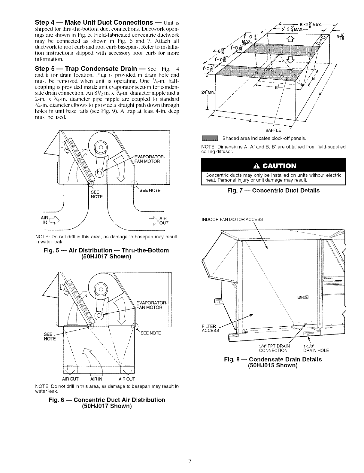
Step 4 -- Make Unit Duct Connections -- Unit is
shipped for thru-the-bottom duct connections. Ductwork open-
ings are shown in Fig. 5. Field-fabricated concentric ductwork
may be connected as shown in Fig. 6 and 7. Attach all
ductwork to roof curb and roof curb basepans. Refer to installa-
tion instructions shipped with accessory roof curb for more
information.
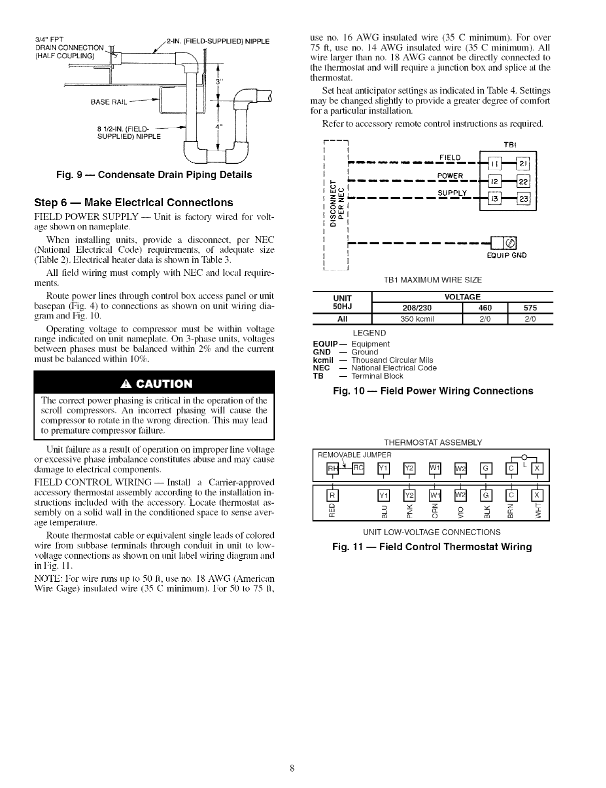
Step 5-- Trap Condensate Drain -- See Fig. 4
and 8 for drain location. Plug is provided in &'ain hole and
must be removed when unit is opelating. One 3/4-in. half-
coupling is provided inside unit evaporator section for conden-
sate drain connection. An 81/2 in. x :V4-in. diameter nipple and a
2-in. x 3/4-in. diameter pipe nipple are coupled to stan&trd
3/4-in. dimneter elbows to provide a straight path down through
holes in unit base rails (see Fig. 9). A trap at least 4-in. deep
must be used.
/EVAPORATOR-
FAN MOTOR
/
/
BAFFLE
Shaded area indicates block-off panels.
NOTE: Dimensions A, A' and B, B' are obtained from field-supplied
ceiling diffuser.
Concentric ducts may only be installed on units without electric
heat. Personal injury or unit damage may result.
Fig. 7 -- Concentric Duct Details
1#cb A,R
_/OUT
NOTE: Do not drill in this area, as damage to basepan may result
in water leak.
Fig. 5 -- Air Distribution -- Thru-the-Bottom
(50HJ017 Shown)
EVAPORATOR-
FAN MOTOR
SEE
NOTE
AIR OUT AIR IN AIR OUT
NOTE: Do not drill in this area, as damage to basepan may result in
water leak.
Fig. 6 -- Concentric Duct Air Distribution
(50HJ017 Shown)
INDOOR FAN MOTOR ACCESS
FILTER
ACCESS
I
3/4" FPT DRAIN 1-3/8"
CONNECTION DRAIN HOLE
Fig. 8 -- Condensate Drain Details
(50HJ015 Shown)
(HALF CO_ L_
8 I12-IN. (FIELD- _"'] I
SUPPLIED) NIPPLE
Fig. 9 -- Condensate Drain Piping Details
Step 6 -- Make Electrical Connections
FIELD POWER SUPPLY -- Unit is factory wired for volt-
age shown on nameplate.
When installing units, provide a disconnect, per NEC
(National Electrical Code) requirements, of adequate size
(Table 2). Electric_d heater data is shown in Table 3.
All field wiring must comply with NEC and local require-
ments.
Route power lines through conhol box access panel or unit
basepan (Fig. 4) to connections as shown on unit wiling dia-
gram and Fig. 10.
Operating voltage to compressor must be within voltage
range indicated on unit nmneplate. On 3-phase units, voltages
between phases must be balanced within 2% and the cunent
must be b_danced within 10%.
The correct power phasing is critical in the operation of the
scroll compressors. An inconect phasing will cause the
compressor to rotate in the wrong direction. This may lead
to premature compressor failure.
Unit failure as a result of operation on improper line voltage
or excessive phase imbalance constitutes abuse and may cause
dmnage to electrical components.
FIELD CONTROL WIRING -- Install a CguTier-approved
accessory fllermostat assembly according to the installation in-
structions included wifll the accessory. Locate thermostat as-
sembly on a solid wall in the conditioned space to sense aver-
age temperature.
Route thermostat cable or equiv_dent single leads of colored
wire fi_)m subbase terminals through conduit in unit to low-
voltage connections as shown on unit label wiring diagram and
in Fig. 11.
NOTE: For wire runs up to 50 It, use no. 18 AWG (American
Wire Gage) insulated wire (35 C minimum). For 50 to 75 It,
use no. 16 AWG insulated wire (35 C minimum). For over
75 It, use no. 14 AWG insulated wire (35 C minimum). All
wire larger than no. 18 AWG cannot be directly connected to
the thermostat and will require a junction box and splice at the
thermostat.
Set heat anticipator settings as indicated in Table 4. Settings
may be changed slightly to provide a greater degree of comfort
for a particuku inst_dlation.
Refer to accessory remote control instructions as lequired.
------'I TBI
I _
I FIELD I f---I F'LM
L ..... POWER I _
.......
1
r
, !
lEQUIP GNO
I
L....................
TB1 MAXIMUM WIRE SIZE
UNIT
50HJ
All
208/230
350 kcmil
LEGEND
EQUIP-- Equipment
GND -- Ground
kcmil -- Thousand Circular Mils
NEC -- National Electrical Code
TB -- Terminal Block
Fig.
VOLTAGE
2/0 2/0
10- Field Power Wiring Connections
THERMOSTAT ASSEMBLY
R E_J U M_]R I_ I_ I_ [_ [_
m m
C3 _ Z Z I--
LU _' Z CC 0 3_, _
cc m o_ 0 _ m m 5:
UNIT LOW-VOLTAGE CONNECTIONS
Fig. 11 -- Field Control Thermostat Wiring
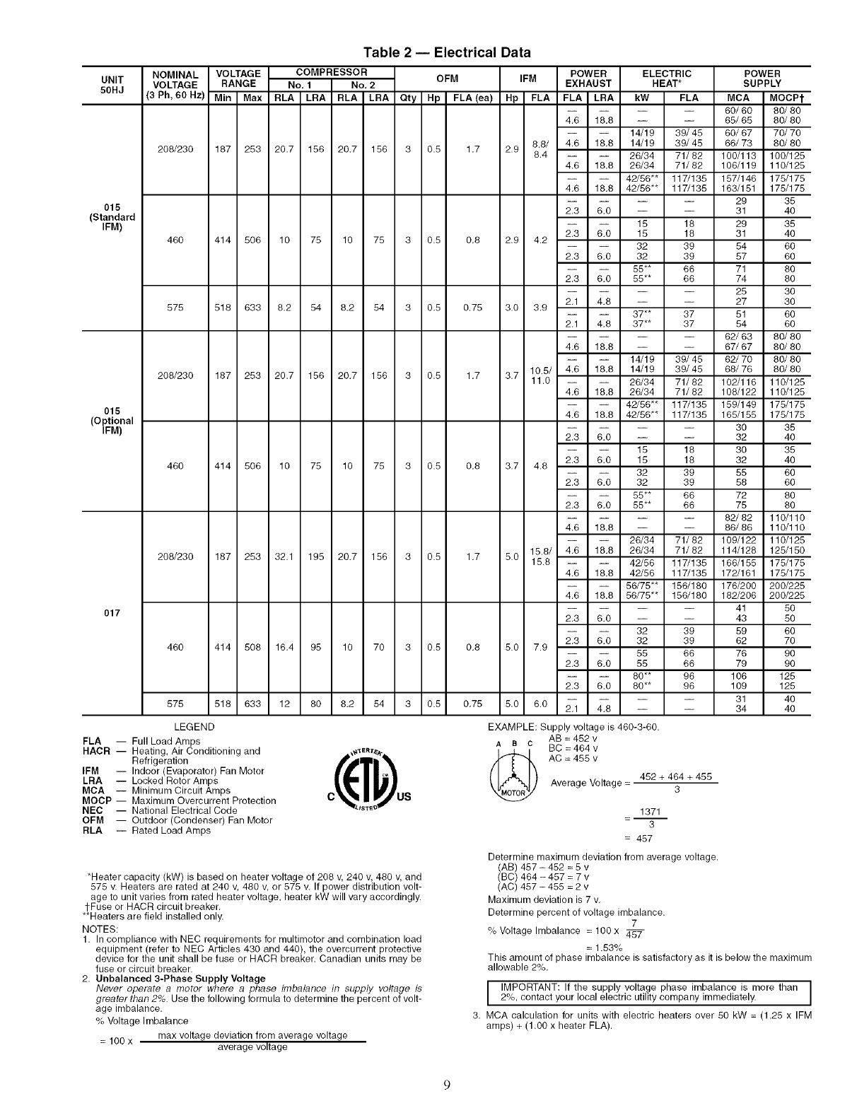
Table 2 -- Electrical Data
UNIT
50HJ
015
(Standard
IFM)
015
(Optional
IFM)
017
NOMINAL VOLTAGE COMPRESSOR OFM IFM POWER ELECTRIC
VOLTAGE RANGE No. 1 No, 2 EXHAUST HEAT*
(3 Ph, 60 Hz) Min Max RLA LRA RLA LRA Qty Hp FLA (ea) Hp FLA FLA LRA kW FLA
208/230 187 253 20.7 156 20.7 156 3 0.5 1.7 2.9
460 414 506 10 75 10 75 3 0.8 0.8 2.9 4.2
575 518 633 8.2 54 8.2 54 3 0.5 0.75 3.0 3.9
POWER
SUPPLY
MCA MOCPt
-- -- 60/60 80/80
4.6 18.8 -- -- 65/65 80/80
14/19 39/45 60/67 70/70
8.8/ 4.6 18.8 14/19 39/48 66/73 80/80
8.4 26/34 71/82 100/113 100/125
4.6 18.8 26/34 71/82 106/119 110/125
42/56"* 117/135 157/146 175/175
4.6 18.8 42/56"* 117/135 163/151 175/175
-- -- 29 35
2.3 6.0 -- -- 31 40
15 18 29 35
2.3 6.0 15 18 31 40
32 39 54 60
2.3 6.0 32 39 57 60
55** 66 71 80
2,3 6,0 55** 66 74 80
-- -- 25 30
2.1 4.8 -- -- 27 30
37** 37 51
2.1 4.8 37** 37 54
208/230 187 253 20.7 156 20.7 156 3 0.5 1.7 3.7
60
60
-- -- 62/63 80/80
4.6 18.8 -- -- 67/67 80/80
14/19 39/45 62/70 80/80
10.5/ 4.6 18.8 14/19 39/45 68/76 80/80
11.0 26/34 71/82 102/116 110/125
4.6 18.8 26/34 71/82 108/122 110/125
42/56"* 117/135 189/149 178/175
4.6 18.8 42/56"* 117/135 165/155 175/175
460 414 506 10 75 10 75 3 0.5 0.8 3.7 4.8
2.3 6.0 --
15
2.3 6.0 15
32
2.3 6.0 32
55**
2.3 6.0 55**
-- 30 35
-- 32 40
18 30 35
18 32 40
39 55 60
39 58 60
66 72 80
66 75 80
-- -- 82/82 110/110
4.6 18.8 -- -- 86/86 110/110
26/34 71/82 109/122 110/125
15.8/ 4.6 18.8 26/34 71/82 114/128 125/150
15.8 42/56 117/135 166/155 175/175
4.6 18.8 42/56 117/135 172/161 175/175
56/75"* 156/180 176/200 200/225
4.6 18.8 56/75"* 156/180 182/206 200/225
208/230 187 253 32.1 195 20.7 156 3 0.5 1.7 5.0
460 414 508 16.4 95 10 70 3 0.5 0.8 5.0 7.9
575 518 633 12 80 8.2 54 3 0.5 0.75 5.0 6.0
-- -- 41 50
2.3 6.0 -- -- 43 50
32 39 59 60
2.3 6.0 32 39 62 70
55 66 76 90
2.3 6.0 55 66 79 90
80** 96 106 128
2.3 6.0 80** 96 109 125
-- -- 31 40
2.1 4.8 -- -- 34 40
LEGEND
FLA -- Full Load Amps
HACR -- Heating, Air Conditioning and
Refrigeration
IFM -- Indoor (Evaporator) Fan Motor
LRA -- Locked Rotor Amps
MCA -- Minimum Circuit Amps
MOCP -- Maximum Overcurrent Protection
NEC -- National Electrical Code
OPM -- Outdoor (Condenser) Fan Motor
RLA -- Rated Load Amps
c t u,
_ISTE_
EXAMPLE: Supply voltage is 460-3-60.
AB = 452 v
Aac BC = 464 v
(_ AC =455 v
Average Voltage = 452 + 464 + 455
3
1371
=-- 3
= 457
*Heater capacity (kW) is based on heater voltage of 208 v, 240 v, 480 v, and
575 v. Heaters are rated at 240 v, 480 v, or 875 v. If power distribution volt-
age to unit varies from rated heater voltage, heater kW will vary accordingly.
l-Fuse or HACR circuit breaker.
**Heaters are field installed only.
NOTES:
1. In compliance with NEC requirements for multimotor and combination load
equipment (refer to NEC Articles 430 and 440), the overcurrent protective
device for the unit shall be fuse or HACR breaker. Canadian units may be
fuse or circuit breaker.
2. Unbalanced 3-Phase Supply Voltage
Never operate a motor where a phase imbalance in supply voltage is
o
greater than 2_. Use the following formula to determine the percent of volt-
age imbalance,
% Voltage Imbalance
= 100 x max voltage deviation from average voltage
average voltage
Determine maximum deviation from average voltage.
(AB) 457 - 452 = 5 v
(BC) 464 -487 = 7 v
(AC) 457 - 455 = 2 v
Maximum deviation is 7 v.
Determine percent of voltage imbalance.
7
% Voltage Imbalance = 100x
= 1.53%
This amount of phase imbalance is satisfactory as it is below the maximum
allowable 2%.
I IMPORTANT: If the supply voltage phase imbalance is more than ]2%, contact your local electric utility company immediately. J
3. MCA calculation for units with electric heaters over 80 kW = (1.25 x IFM
amps) + (1.00 x heater FLA).

Table 3 -- Electric Resistance Heater Data
UNIT
50HJ
015
017
HEATER kW
Unit Voltages HEATER %HEAT MAXIMUM
STAGES PER STAGES*
208 230 240 460 480 575 600 STAGE
14 17 19 14 15 1 100 1
26 31 34 30 32 2 50/50 2
42 52 56 50 55 37 40 2 33/67 3
26 31 34 30 32 2 50/50 2
42 52 56 50 55 2 33/67 3
56 69 75 73 80 2 50/50 4
MINIMUM
Heating Cfm
Cfm L/s
3750 1770
208 230
39.3 43.4
71.3 78.9
117.0 129.4
71.3 78.8
117.0 129.4
155.9 172.4
3750 1770
*Maximum number of stages using accessory low-ambient kit or head pressure control device and low-ambient kit.
NOTE: Heaters are rated at 240,480, and 575 v.
HEATER AMPS
240 460 480
45.3 17.2 17.9
82.3 37.3 39.0
135.0 63.3 66.1
82.3 37.3 39.0
135.0 63.3 66.1
179.9 92.0 96.0
575 600
37.0 38.6
Table 4 -- Heat Anticipator Settings
UNIT
50HJ
015, 017
UNIT kW* STAGE 1
VOLTAGES
14/19 .40
26/34 .40
208/230-3-60 42/56 .66
56/75 .66
15 .40
32 .40
480-3-60 55 .40
80 .66
575-3-60 37 .66
*Heater kW is based on heater voltage of
STAGE 2
.66
.40
.66
.40
.66
.66
.66
208 v, 240 v, 480 v, and 575 v.
OPTIONAL NON-FUSED DISCONNECT -- On units with
the option_fl non-fused disconnect, incoming power will be
wired into the disconnect switch. Refer to Fig. 12 for wiring
for 100 and 200 amp disconnect switches. Units with an
MOCP (maximum overcurrent protection) under 100 will use
the 100 amp disconnect switch. Units with an MOCP over 100
will use the 200 amp disconnect switch. Refer to the applicable
disconnect wiring diagrmn.
To prevent breakage during shipping, the disconnect handle
and shaft ale shipped and packaged inside the unit control box.
Install the disconnect handle before unit operation. To install
the handle and shaft, perform the following procedure:
1. Open the control box door and remove the handle and
shaft from shipping location.
2. Ix_osen the Allen bolt located on the disconnect switch.
The bolt is located on the square hole and is used to hold
the shaft in place. The shaft cannot be inserted until the
Allen bolt is moved.
3. Insert the disconnect shaft into the sqmue hole on the dis-
connect switch. The end of the shaft is specially cut and
the shaft can only be inserted in the correct orientation.
UNIT WIRING 6T3 4T2 2T1 LOAD
100 BLK. YEL. BLU.
AMP
1
I , I
INoNFUSED0'sODNNEOT __L LIN J
FIELD POWER SUPPLY 5L3 3L2 1L1 LINE
UNIT WIRING
200 BLK. YEL. BLU.
AMP ,
I NON FUSED DISCONNECT LINE 1
FIELD POWER SUPPLY
NOTE: The disconnect takes the place of TB-1 as shown on the unit wir-
ing diagram label and the component arrangement label.
Fig. 12 -- Optional Non-Fused Disconnect Wiring
4. Tighten the Allen bolt to lock the shaft into position.
5. Close the control box dool:
6. Attach the handle to the external access door with the two
screws provided. When the handle is in the ON position,
the handle will be vertical. When the handle is in the OFF
position, the handle will be horizontal.
7. Turn the handle to the OFF position and close the dool:
The handle should fit over the end of the shaft when the
door is closed.
8. The handle must be in the OFF position to open the con-
trol box door.
OPTIONAL CONVENIENCE OUTLET-- On units with
optional convenience outlet, a l15-v GFI (ground fault inter-
rupt) convenience outlet receptacle is provided for field wiring.
Field wiring should be run through the 7/_-in. knockout pro-
vided in the basepan near the return air opening.
Step 7 -- Make Outdoor-Air Inlet Adjustments
MANUAL OUTDOOR-AIR DAMPER -- All units (except
those equipped with a factory-installed economizer) have a
manual outdoor-tdr damper to provide ventilation all: Damper
can be preset to adinit up to 25% outdoor tdr into return-air
compartment. To adjust, loosen securing screws and move
damper to desired setting. Then retighten screws to secure
damper (Fig. 13).
Step 8 -- Install Outdoor-Air Hood
IMPORTANT: If the unit is equipped with the optiomd
EconoMiSerIV component, move the outdoor-air tempera-
ture sensor prior to installing the outdoor-air hood. See the
Optional EconoMiSerIV and Economi$er2 section for
more information.
The same type of factory-installed hood is used on units
with 25% air ventilation and units with an EconoMiSel:
NOTE: The hood top panel, upper and lower filter retainers,
hood diain pan, baffle (size 017 units), and filter support
bracket tu'e secured opposite the condenser end of the unit. The
25% ADJUSTABLE
AIR DAMPER
÷I
SECURING SCREWS
Fig. 13 -- 25% Outdoor-Air Section Details
BASE
UNIT
10
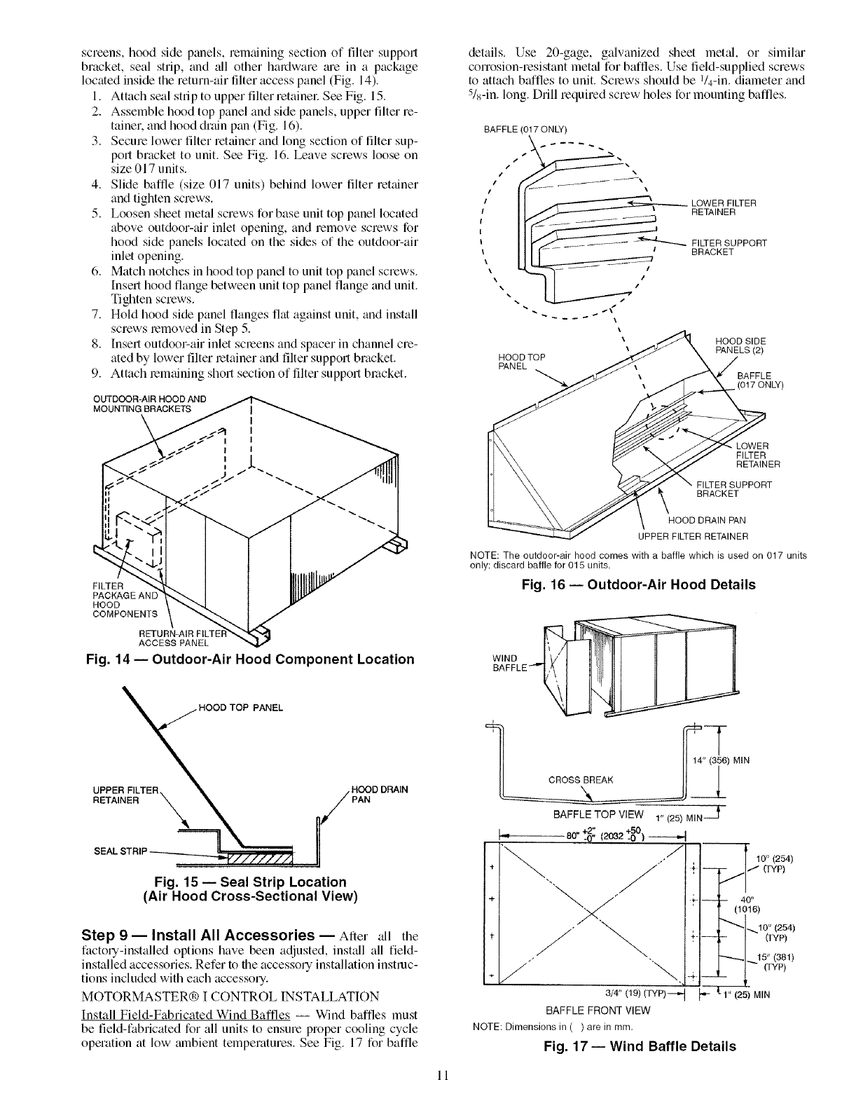
screens, hood side panels, remaining section of filter support
bracket, seal strip, and all other hardware me in a package
located inside the return-air filter access panel (Fig. 14).
1+ Attach seal strip to upper filter retainel: See Fig. 15.
2. Assemble hood top panel and side panels, upper filter re-
tainer, and hood diain pan (Fig. 16)+
3. Secure lower filter retainer and long section of filter sup-
port bracket to unit. See Fig+ 16. Leave screws loose on
size 017 units.
4. Slide baffle (size 017 units) behind lower filter retainer
and tighten screws.
5. Loosen sheet metal screws for base unit top panel located
above outdoor-air inlet opening, and remove screws for
hood side panels located on the sides of the outdoor-air
inlet opening.
6. Match notches in hood top panel to unit top panel screws.
Insert hood flange between unit top panel flange and unit.
Tighten screws.
7+ Hold hood side panel flanges flat against unit, and install
screws removed in Step 5+
8+ Insert outdoor-air inlet screens and spacer in channel cre-
ated by lower filter retainer and filter support bracket.
9+ Attach remaining short section of filter support bracket+
OUTDOOR-AIR HOOD AND
MOUNTING BRACKETS
details. Use 20-gage, galvanized sheet metal, or similm
corrosion-resistant metal for baffles. Use field-supplied screws
to attach baffles to unit. Screws should be I/4-in. diameter and
5/8-in. long. Drill required screw holes for mounting baffles.
BAFFLE (017 ONLY)
LOWER FILTER
RETAINER
FILTER SUPPORT
BRACKET
\
HOOD SIDE
\PANELS (2)
HOOD TOP
PANEL
BAFFLE
• (017 ONLY)
FILTER
PACKAGE AN[
HOOD
COMPONENfS
RETURN-AIR FtLTE}
ACCESS PANEL
Fig. 14- Outdoor-Air Hood Component Location
TOP PANEL
UPPER FILTER. HOOD DRAIN
RETAINER X PAN
Fig. 15 -- Seal Strip Location
(Air Hood Cross-Sectional View)
Step 9 -- Install All Accessories -- After all the
factory-installed options have been adjusted, install all field-
installed accessories. Refer to the accessory installation instruc-
tions included with each accessory.
MOTORMASTER® I CONTROL INSTALLATION
Install Field-Fabricated Wind Baffles -- Wind baffles must
be field-fabricated for all units to ensure proper cooling cycle
operation at low mnbient temperatures. See Fig+ 17 for baffle
LOWER
FI_ER
RETAINER
BRACKET
HOOD DRAIN PAN
UPPER FILTER RETAINER
NOTE: The outdoor-air hood comes with a baffle which is used on 017 units
only; discard baffle for 015 units.
Fig. 16- Outdoor-Air Hood Details
) MIN
BAFFLETOP VIEW 1" (25) MIN--_
I= 80- to%---4
/
/.
"%
÷ _ "+.
+ j÷-
+J \,+
3/4" 09)(_P)-+J _
BAFFLEFRONTVIEW
NOTE: Dimensions in ( ) are in mm.
Fig. 17- Wind Baffle Details
Jl 10" (254)
/" ffYp)
-- 40"
(to16)
,..,10" (254)
- (TYP)
"'-_1_+ 5"(381)
__ (TYP)
1" (25) MIN
11
To avoid dmnage to tile refiigerant coils and electrical com-
ponents, use recommended screw sizes only. Use cme
when &illing holes.
Install Motormaster [Controls -- Only one Motormaster I
control is required per unit. The Motormaster [control must be
used in conjunction with the accessory 0 ° F low mnbient kit
(purchased separately). The Motormaster I device controls out-
door fan no. 1 while outdoor fans no. 2 and 3 are sequenced off
by the accessory 0° F low ambient kit.
A_zessorv 0 °F Low Ambient Kit -- Install the accessory 0° F
low ambient kit per instruction supplied with accessory.
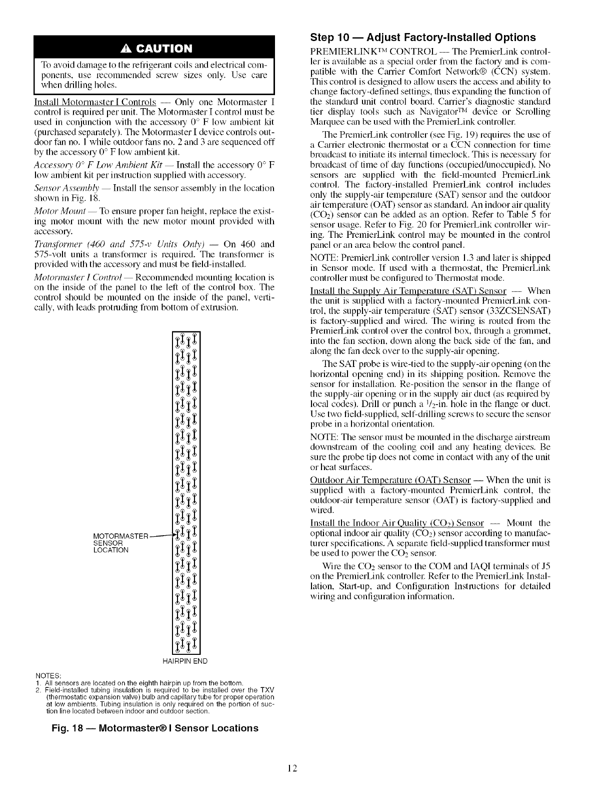
Sensor Assembly -- Install the sensor assembly in the location
shown in Fig. 18.
Motor Mount -- To ensure proper fan height, replace file exist-
ing motor mount with the new motor mount provided with
accessory.
Tran@nw_er (460 and 575-v Units Only) -- On 460 and
575-volt units a transformer is required. The transformer is
provided with the accessory and must be field-installed.
MotormasWr I Control -- Recommended mounting location is
on the inside of the panel to the left of the control box. The
control should be mounted on the inside of the panel, verti-
c:dly, with leads protruding from bottom of extrusion.
MOTORMASTER-------
SENSOR
LOCATION
i
HAIRPIN END
NOTES:
1. All sensors are located on the eighth hairpin up from the bottom.
2. Field-installed tubing insulation is required to be installed over the TXV
(thermostatic expansion valve) bulb and capillary tube for proper operation
at low ambients. Tubing insulation is only required on the portion of suc-
tion line located between indoor and outdoor section.
Fig. 18 -- Motormaster_) I Sensor Locations
Step 10- Adjust Factory-Installed Options
PREMIERLIN K TM CONTROL -- The PrelnierLink control-
let is available as a special order from the factory and is com-
patible with the Cmrier Comfort Network® (CCN) system.
This control is designed to allow use_ the access and ability to
change factory-defined settings, thus expanding the function of
the stan&trd unit control board. Carrier's diagnostic stan&trd
tier display tools such as Navigato( r_'_ device or Scrolling
Marquee c_m be used with the PremierLink controlle_:
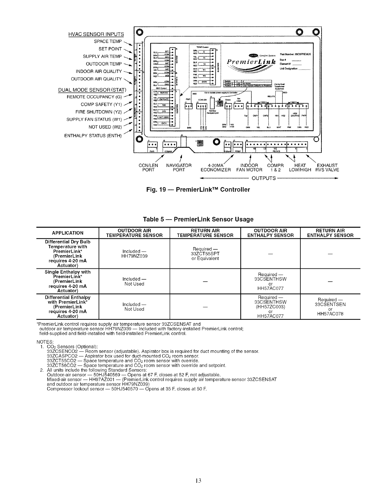
The PremierLink controller (see Fig. 19) requires the use of
a Cmrier electronic thermostat or a CCN connection for time
broadcast to initiate its internal timeclock. This is necessary for
broadcast of time of day functions (occupied/unoccupied). No
sensors are supplied with the field-mounted PremierLink
control. The factory-installed PremierLink control includes
only the supply-air temperature (SAT) sensor and the outdoor
air temperature (OAT) sensor as standard. An indoor air quality
(CO2) sensor can be added as an option. Refer to Table 5 for
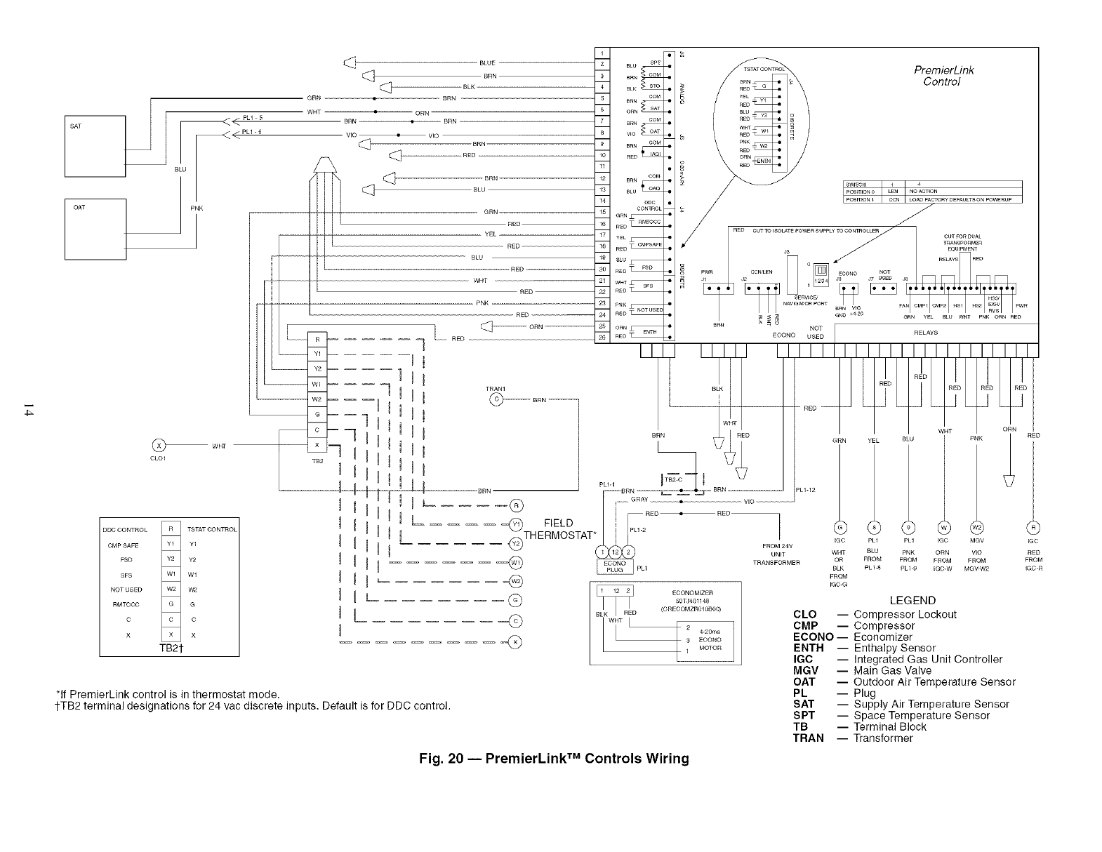
sensor usage. Refer to Fig. 20 for PremierLink controller wir-
ing. The PremierLink control may be mounted in the control
panel or an mea below the control panel.
NOTE: PremierLink controller version 1.3 and kiter is shipped
in Sensor mode. If used with a fl_ermostat, the PremierLink
controller must be configured to Thermostat mode.
Install the Supply Air Temperature (SAT) Sensor -- When
the unit is supplied with a factory-mounted PremierLink con-
trol, the supply-air temperature (SAT) sensor (33ZCSENSAT)
is factory-supplied and wired. The wiring is routed from the
PremierLink control over the control box, through a grommet,
into the fan section, down along the back side of the fan, and
along the fan deck over to the supply-air opening.
The SAT probe is wire-tied to the supply-air opening (on the
horizontal opening end) in its shipping position. Remove the
sensor for installation. Re-position the sensor in the flange of
the supply-air opening or in the supply air duct (as required by
loc_d codes). Drill or punch a 1/2-in. hole in the flange or duct.
Use two field-supplied, self-drilling screws to secure the sensor
probe in a horizontal orientation.
NOTE: The sensor must be mounted in the discharge airstream
downstream of file cooling coil and any heating devices. Be
sure the probe tip does not come in contact with any of the unit
or heat surfaces.
Outdoor Air Temperature (OAT) Sensor -- When the unit is
supplied with a factory-mounted PremierLink control, the
outdoor-air temperature sensor (OAT) is factory-supplied and
wired.
Install the Indoor Air Quality (COa2 Sensor -- Mount the
optional indoor air quality (CO2) sensor according to manufac-
turer specifications. A separate field-supplied transformer must
be used to power the CO2 sensor:
Wire the CO2 sensor to the COM and IAQI terminals of J5
on the PremierLink controlle_: Refer to the PremierLink Instal-
kition, Start-up, and Configuration Instructions for detailed
wiring and configuration information.
12
HVAC SENSOR INPUTS
SPACE TEMP
SET POINT
SUPPLY AIR TEMP
OUTDOOR TEMP
INDOOR AIR QUALITY
OUTDOOR AIR QUALITY
DUAL MODE SENSOR (STAT)
COMP SAFETY (Y1) 7
FIRE SHUTDOWN (Y2) /
SUPPLY FAN STATUS (Wl)
NOT USED (W2) /
ENTHALPY STATUS (ENTH)
O
O
O
(
_STATC_ !
_RN i C _s} _ Fatt Nmnboc &_OSPREMLK
=o_]oi PremlerL_nk ..... --
/- t/t"4 "-4 "-..
CCN/LEN NAVIGATOR 4-20MA INDOOR COMPR HEAT EXHAUST
PORT PORT ECONOMIZER FAN MOTOR 1 & 2 LOW/HIGH RVSVALVE
OUTPUTS
Fig. 19- PremierLink TM Controller
Table 5 -- PremierLink Sensor Usage
OUTDOOR AIR RETURN AIR OUTDOOR AIR RETURN AIR
APPLICATION TEMPERATURE SENSOR TEMPERATURE SENSOR ENTHALPY SENSOR ENTHALPY SENSOR
Differential Dry Bulb
Temperature with Required --
PremierLink* Included -- 33ZCT55SPT -- --
(PremierLink HH79NZ039 or Equivalent
requires 4-20 mA
Actuator)
Single Enthalpy with Required --
PremierLink* Included -- 33CSENTHSW
(PremierLink Not Used -- or --
requires 4-20 mA HH57AC077
Actuator)
Differential Enthalpy Required -- Required --
with PremierLink* Included- 33CSENTHSW 33CSENTSEN
(PremierLink Not Used -- (HH57ZC003) or
requires 4-20 mA or HH57AC078
Actuator) H H57AC077
*PremierLink control requires supply air temperature sensor 33ZCSENSAT and
outdoor air temperature sensor HH79NZ039 -- Included with factory-installed PremierLink control;
field-supplied and field-installed with field-installed PremierLink control.
NOTES:
1. CO2 Sensors (Optional):
33ZCSENCO2 -- Room sensor (adjustable). Aspirator box is required for duct mounting of the sensor.
33ZCASPCO2 -- Aspirator box used for duct-mounted CO2 room sensor.
33ZCT55CO2 -- Space temperature and CO2 room sensor with override.
33ZCT56CO2 -- Space temperature and CO2 room sensor with override and setpoint.
2. All units include the following Standard Sensors:
Outdoor-air sensor -- 50HJ540569 -- Opens at 67 F,closes at 52 F,not adjustable.
Mixed-air sensor -- HH97AZ001 -- (PremierLink control requires supply air temperature sensor 33ZCSENSAT
and outdoor air temperature sensor HH79NZ039)
Compressor lockout sensor -- 50HJ540570 -- Opens at 35 E closes at 50 E
13
T_
SAT
OAT
_<PU-6
BLU
w_
CLOl
BLUE
[_ BRN
BLK
GRN BRN
WHT •ORN
BRN •
VIO •VIO
RED BRN
[_ BLU
__ GRN
RED
- -- YEL --
RED
BLU
RED
WHT
RED
- PNK
_ RED
_ _-- RE
DDC CONTROL R TSTAT CONTROL
CMP SAFE Y1 Y1
FSD Y2 Y2
SFS Wl Wl
NOT USED W2 W2
RMTOCC G G
C C C
X X X
TB21-
R
Y1
Y2
Wl
W2 -- -- --
G
x
TB2
I t
U _
n I
I IU!
U IUL
n
U
BLU SPT
_N COM
_LK _
tOM
C_
_RN tOM
_o _
BRN COM
£ED_
C_
_L_
eoc
CONTROL
GRN_
RED _
YEL_
RED _
£EO_
WHT_
REO_
C_
ORN_
RED_
PremierLink
Control
*If PremierLink control is in thermostat mode,
1-TB2 terminal designations for 24 vac discrete inputs, Default is for DDC control.
I.....
posmoN0 LEN NO AC_ON
POS_ON 1 CCN LOAD FACTORy DEFAULTS ON POWERUP
OON-- °L'I REDII I
_TH EFIELDTAT_ 2 _24v _ _ ......
I_L_ ORN VIO RED
"(_ _pLl TRANsUN;MER tO: ' F_L_c_K9 :R(_O_, M_RvO_2 :GRcOM
EGC-G
GLEGEND
CLO -- Compressor Lockout
CMP -- Compressor
ECONO- Economizer
ENTH -- Enthalpy Sensor
IGC -- Integrated Gas Unit Controller
MGV -- Main Gas Valve
OAT -- Outdoor Air Temperature Sensor
PL -- Plug
SAT -- Supply Air Temperature Sensor
SPT -- Space Temperature Sensor
TB -- Terminal Block
TRAN -- Transformer
©
Q
ECONOMIZER
50TJ401148
(CREOOMZR010800)
4.20ma
3 ECONO
1 MOTOR
Fig. 20 -- PremierLink TM Controls Wiring
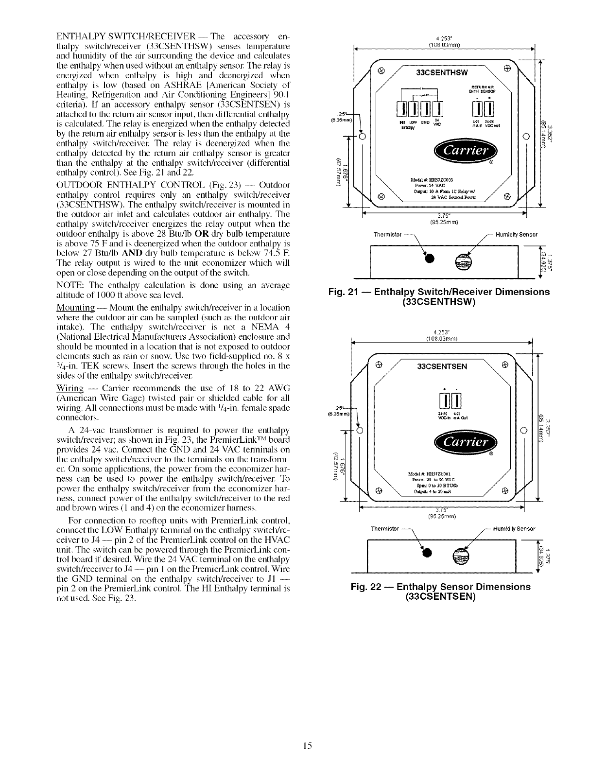
ENTHALPY SWITCH/RECEIVER -- The accessory en-
thalpy switch/receiver (33CSENTHSW) senses temperature
and humidity of the air surrounding the device and calculates
the enthalpy when used without tin enthtdpy sensol: The relay is
energized when enthalpy is high and deenergized when
enthalpy is low (based on ASHRAE [American Society of
Heating, Refiigerafion and Air Conditioning Engineersl 90.1
criteria). If an accessory enthalpy sensor (33CSENTSEN) is
attached to the return air sensor input, then differential enthalpy
is ctdculatedi The relay is energized when the enthalpy detected
by the return air enthalpy sensor is less than the enthtdpy at the
enthalpy switch/receivel: The relay is deenergized when the
enthalpy detected by the return air enthalpy sensor is greater
than the enthalpy at the enthalpy switch/receiver (differential
enthtdpy control). See Fig. 21 and 22.
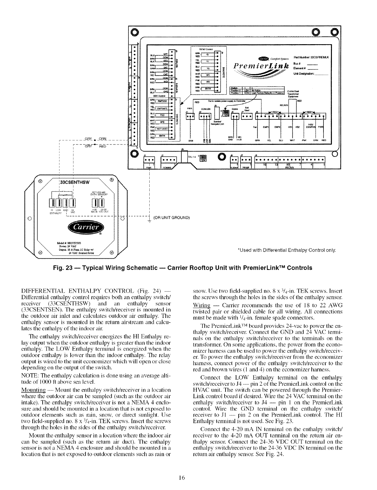
OUTDOOR ENTHALPY CONTROL (Fig. 23) -- Outdoor
enthalpy control requires only tin enthalpy switch/receiver
(33CSENTHSW). The enthalpy switch/receiver is mounted in
the outdoor air inlet and calculates outdoor air enthalpy. The
enthalpy switch/receiver energizes the relay output when the
outdoor enthalpy is above 28 Btu/lb OR din bulb temperature
is above 75 F and is deenergized when file outdoor enthalpy is
below 27 Btu/lb AND dUbulb temperature is below 74.5 E
The relay output is wired to the unit economizer which will
open or close depending on the output of the switch.
NOTE: The enthalpy calculation is done using tin average
altitude of 1000 ft above sea level.
Mounting -- Mount the enthalpy switch/receiver in a location
where the outdoor air can be sampled (such as the outdoor air
intt&e). The enthtdpy switchheceiver is not a NEMA 4
(National Electrical Manufacturers Association) enclosure and
should be mounted in a location that is not exposed to outdoor
elements such as rain or snow. Use two field-supplied no. 8 x
3/4-in. TEK screws. Insert the screws through the holes in the
sides of the enthalpy switch/receivel:
Wiring -- Carrier recommends the use of 18 to 22 AWG
(American Wire Gage) twisted pair or shielded cable for all
wiring. All connections must be made with l/4-in, female spade
connectors.
A 24-vac transformer is required to power the enthtdpy
switch/receiver; as shown in Fig. 23, the PremierLink TM board
provides 24 vac. Connect the GND and 24 VAC temrinals on
the enthalpy switch/receiver to the termimfls on the transform-
el: On some applications, the power fi_m the economizer har-
ness can be used to power the enthalpy switch/receivec To
power the enthalpy switch/receiver from the economizer har-
ness, connect power of the enthalpy switch/receiver to the red
and brown wires (1 and 4) on the economizer harness.
For connection to roollop units with PremierLink control,
connect the LOW Enthalpy terminal on the enthalpy switch/re-
ceiver to J4 -- pin 2 of the PremierLink control on the HVAC
unit. The switch can be powered through the PremierLink con-
trol board if desired. Wire file 24 VAC terminal on file enthalpy
switchheceiver to J4 -- pin 1on the PremierLink control. Wire
the GND termimd on file enthalpy switch/receiver to Jl --
pin 2 on the PremierLink control. The HI Enthalpy terminal is
not used. See Fig. 23.
25"-,--
(8 35ram)
ulb_
+'4"4
4253"
(108 03ram) IP
into
Thermistor --_ S Humidity Sensor
Fig. 21 -- Enthalpy Switch/Receiver Dimensions
(33CSENTHSW)
25'*- --
(6 35rnm)
4253"
(I 08 03turn)
¢to 3OmA
375"
(95 25rnm)
Thermistor -_
IJ,
c_ _o
S HurnMity Sensor
N_
Fig. 22 -- Enthalpy Sensor Dimensions
(33CSENTSEN)
15
/
o
\
GRY eORN
-- -- _GRY _e RED
E
E
UA _ V_COUr
gNT_tA_ _'Y
p_: _ VAC
_: loA F_ I¢ P_hy_!
24 VAC So_a Po_
0f
O_'J1
0 0
....... (OR UNIT GROUND)
*Used with Differential Enthalpy Control only.
Fig. 23 -- Typical Wiring Schematic -- Carrier Rooftop Unit with PremierLink TM Controls
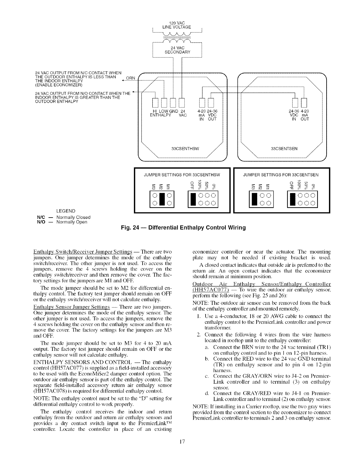
DIFFERENTIAL ENTHALPY CONTROL (Fig. 24) --
Differential enthalpy control requires both an enthalpy switch/
receiver (33CSENTHSW) and an enthalpy sensor
(33CSENTSEN). The enthalpy switch/receiver is mounted in
the outdoor air inlet and calculates outdoor air enthalpy. The
enthalpy sensor is mounted in the return airstream and calcu-
lates the enthalpy of the indoor ai_:
The enthalpy switch/receiver energizes the HI Enthalpy re-
lay output when the outdoor enthalpy is greater than the indoor
enthalpy. The LOW Enth_dpy terminal is energized when the
outdoor enth_dpy is lower than the indoor enthalpy. The relay
output is wired to the unit economizer which will open or close
depending on the output of the switch.
NOTE: The enthalpy calculation is done using an average _flti-
tude of 1000 ft above sea level.
Mounting -- Mount the enthalpy switchheceiver in a location
where the outdoor air can be sampled (such as the outdoor air
intake). The enthalpy switch/receiver is not a NEMA 4 enclo-
sure and should be mounted in a location that is not exposed to
outdoor elements such as rain, snow. or direct sunlight. Use
two field-supplied no. 8 x 3/4-in. TEK screws. Insert the screws
through the holes in the sides of the enth_dpy switch/receive_:
Mount the enthalpy sensor in a location where the indoor air
can be sampled (such as the return air duct). The enthalpy
sensor is not a NEMA 4 enclosure and should be mounted in a
location that is not exposed to outdoor elements such as rain or
snow. Use two field-supplied no. 8 x 3/4-in. TEK screws. Inset1
the screws through the holes in the sides of the enthalpy sensor:
Wiring -- Carrier recommends the use of 18 to 22 AWG
twisted pair or shielded cable for all wiring. All connections
must be made with I/4-in. female spade connectors.
The PremierLink TM board provides 24-vac to power the en-
thalpy switch/receive_: Connect the GND and 24 VAC termi-
nals on the enth_dpy switch/receiver to the terminals on the
transformec On some applications, the power from the econo-
mizer harness can be used to power the enthalpy switch/receiv-
e_: To power the enthalpy switch/receiver from the economizer
harness, connect power of the enthalpy switch/receiver to the
red and brown wires (1 and 4) on the economizer hmness.
Connect the LOW" Enthalpy terminal on the enthalpy
switch/receiver to J4 -- pin 2 of the PremierLink control on the
HVAC unit. The switch can be powered through the Premier-
Link control board if desired. Wire the 24 VAC terminal on the
enthalpy switchheceiver to J4 -- pin 1 on the PremierLink
control. Wire the GND terminal on the enthalpy switch/
receiver to Jl -- pin 2 on the PremierLink control. The HI
Enthalpy termimd is not used. See Fig. 23.
Connect the 4-20 mA IN terminal on the enthalpy switch/
receiver to the 4-20 mA OUT terminal on the return air en-
thalpy sensor: Connect the 24-36 VDC OUT terminal on the
enthalpy switch/receiver to the 24-36 VDC IN terminal on the
return air enth_dpy sensoc See Fig. 24.
16
120 VAC
LINE VOLTAGE J
24 VAC OUTPUT FROM N/C CONTACT WHEN
THE OUTDOOR ENTHALPY IS LESS THAN
THE INDOOR ENTHALPY
(ENABLE ECONOMIZER)
ORN
24 VAC OUTPUT FROM N/O CONTACT WHEN THE
INDOOR ENTHALPY IS GREATER THAN THE
OUTDOOR ENTHALPY
f
,/
HI LOW GND 24
ENTHALPY VAC 4-20 24-36
rnA VDC
IN OUT
"_ 33CSENTHSW
/
/
24-36 4-20
VDC rnA
IN OUT
"_ 33CSENTSEN
LEGEND
N/C -- Normally Closed
N/O -- Normally Open
JUMPER SETTINGS FOR 33CSENTHSW
o _ o_
_ _ooo
II°°°
000
JUMPER SETTINGS FOR 33CSENTSEN
O o ol
CO IX)
Fig. 24- Differential Enthalpy Control Wiring
Enthalpy Switch/Receiver Jumper Settings -- There are two
jumpel.s. One jumper determines the mode of file enthalpy
switchheceivel: The other jumper is not used. To access the
jumpel.s, remove the 4 screws holding the cover on the
enthalpy switch/receiver and then remove the covel: The fac-
tory settings for the jumpers are MI and OFF.
The mode jumper should be set to M2 for differential en-
thalpy control. The factory test jumper should remtdn on OFF
or the enthalpy switch/receiver will not calculate enthalpy.
Enthalpy Sensor Jumper Settings -- There are two jumpers.
One jumper determines the mode of the enthalpy sensor The
other jumper is not used. To access the jumpers, remove the
4 screws holding the cover on the enthalpy sensor and then re-
move the covel: The factory settings for the jumpers _ue M3
and OFF.
The mode jumper should be set to M3 for 4 to 20 mA
output. The factory test jumper should lemain on OFF or the
enthalpy sensor will not calculate enthalpy.
ENTHALPY SENSORS AND CONTROL -- The enth;dpy
control (HH57AC077) is supplied as a field-installed accessory
to be used with the EconoMiSer2 damper control option. The
outdoor air enth;dpy sensor is part of the enthalpy control. The
separate field-installed accessory return air enthalpy sensor
(HH57AC078) is required for differential enthalpy control
NOTE: The enthalpy control must be set to the "D" setting for
differential enthalpy control to won properly.
The enthalpy control receives the indoor and return
enthalpy from the outdoor and return air enthalpy sensors and
provides a @ contact switch input to the PremierLing TM
controllel: Locate the controller in place of an existing
economizer controller or near the actuatol: The mounting
plate may not be needed if existing bracket is used.
A closed contact indicates that outside air is preferred to the
return ai_: An open contact indicates that the economizer
should remain at minimum position.
Outdoor Air Enthalpy Sensor/Enthalpy Controller
(HH57AC077) -- To wire the outdoor air enthalpy sensor.
perform the following (see Fig. 25 and 26):
NOTE: The outdoor air sensor can be removed from the back
of the enthalpy controller and mounted remotely.
1. Use a 4-conductor. 18 or 20 AWG cable to connect the
enth_flpy control to the PremierLink controller and power
transformer
2. Connect the following 4 wires from the wire harness
located in rooftop unit to the enthalpy controller:
a. Connect the BRN wire to the 24 vac terminal (TRI)
on enthalpy control and to pin 1 on 12-pin harness.
b. Connect the RED wire to the 24 vac GND terminal
(TR) on enthalpy sensor and to pin 4 on 12-pin
harness.
c. Connect the GRAY/ORN wire to J4-2 on Premier-
Link controller and to terminal (3) on enthalpy
sensoE
d. Connect the GRAY/RED wire to J4-1 on Premier-
Link controller and to terminal (2) on enthalpy sensw:
NOTE: If installing in a Carrier rooftop, use the two gray wires
provided from the control section to the economizer to connect
PremierLink controller to termimds 2 and 3 on enthalpy sensol:
17
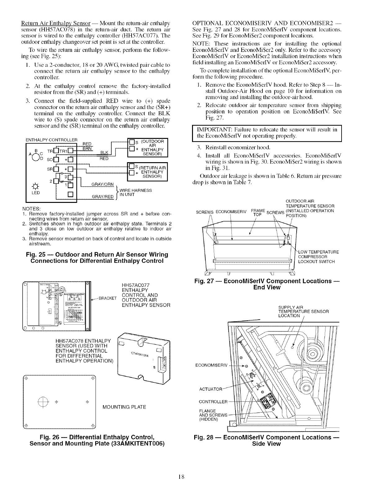
Return Air Enthalpy Sensor -- Mount the return-air enthalpy
sensor (HH57AC078) in the return-air duct. The return air
sensor is wired to the enth_dpy controller (HH57AC077). The
outdoor enth_dpy changeover set point is set at the controller.
To wire the return air enthalpy sensor, perform the follow-
ing (see Fig. 25):
1. Use a 2-conductor. 18 or 20 AWG, twisted pair cable to
connect the return air enthalpy sensor to the enthalpy
controller.
2.
3.
At the enthalpy control remove the factory-installed
resistor from the (SR) and (+) termin_ds.
Connect the field-supplied RED wire to (+) spade
connector on the return air enthalpy sensor and the (SR+)
terminal on the enthalpy controllel: Connect the BLK
wire to (S) spade connector on the return air enthalpy
sensor and the (SR) terminal on the enthalpy controllel:
ENTHALPY CONTROLLER [_
RED S (OUTDOOR
AIR
TRr'_TRI_- BRN + ENTHALPY
SENSOR)
sor
SR¢'I+lD"
LED
--q
BLK
RED
I [] S (RETURN AIR ]
r] + ENTHALPY
-- SENSOR
GRAY/ORN
LWIRE HARNESS
GRAY/RED JlN UNIT
NOTES:
1. Remove factory-installed jumper across SR and + before con-
necting wires from return air sensor.
2, Switches shown in high outdoor air enthalpy state. Terminals 2
and 3 close on low outdoor air enthalpy relative to indoor air
enthalpy.
3. Remove sensor mounted on back of control and locate in outside
airstream.
Fig. 25 -- Outdoor and Return Air Sensor Wiring
Connections for Differential Enthalpy Control
HH57AC077
ENTHALPY
CONTROL AND
OUTDOOR AIR
ENTHALPY SENSOR
HH57AC078 ENTHALPY
SENSOR(USED WITH
ENTHALPY CONTROL
FOR DIFFERENTIAL
ENTHALPY OPERATION)
÷÷MOUNTING PLATE
Fig. 26 -- Differential Enthalpy Control,
Sensor and Mounting Plate (33AMKITENT006)
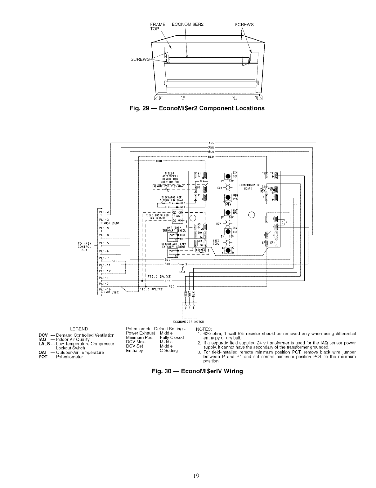
OPTIONAL ECONOMISERIV AND ECONOM[$ER2 --
See Fig. 27 and 28 for EconoMiSerIV component locations.
See Fig. 29 for EconoMi$er2 component locations.
NOTE: These instructions are for installing the optional
EconoMiSerIV and EconoMiSer2 only. Refer to the accessory
EconoMiSerIV or EconoMiSer2 installation instructions when
field installing an EconoMi$erIV or EconoMiSer2 accesso q.
To complete inst_dlation of the optional EconoMiSerIV. per-
form the following procedure.
1. Remove the EconoMiSerIV hood. Refer to Step 8 --[n-
stall Outdoor-Air Hood on page 10 for information on
removing and installing the outdoor-air hood.
2. Relocate outdoor air temperature sensor from shipping
position to operation position on EconoMiSerIV. See
Fig. 27.
IMPORTANT: Failure to relocate the sensor will result in
the EconoMiSerlV not operating properly.
3. Reinstall economizer hood.
4. Install all EconoMiSerIV accessories. EconoMiSeltV
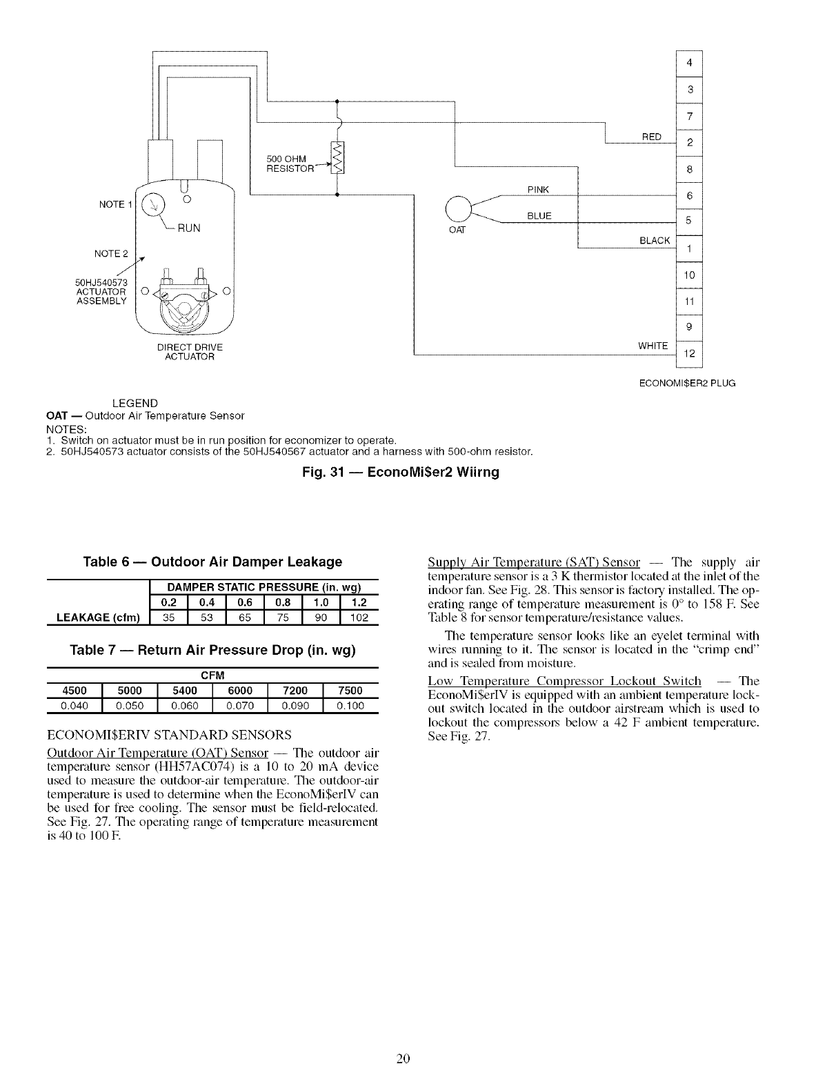
wiring is shown in Fig. 30. EconoMiSer2 wiring is shown
in Fig. 31.
Outdoor air leakage is shown in Table 6. Return air pressure
drop is shown in Table 7.
OUTDOOR AIR
TEMPERATURE SENSOR
SCREWS ECONOMI$ERIV FTRAME SCR}EWS (/NSsTALoLN_D OPERATION
I ! LOW TEMPERATURE
I i COMPRESSOR
LOCKOUT SWITCH
_g kv _J
Fig. 27 -- EconoMi$erlV Component Locations --
End View
SUPPLY AIR
TEMPERATURE SENSOR
LOCATION
ECONOMI$ERIV
FLANGE
(HIDDEN)
r
Fig. 28 -- EconoMi$erlV Component Locations --
Side View
18
FRAME ECONOMIBER2
SCREWS _i !
_J
SCREWS
Fig. 29 -- EconoMi$er2 Component Locations
LI_4
LI-B
-{NOI USED}
LI-9
m
PLI-8
TO MAIN PLI*5
CONTROL
BOX
PLI-I
PLI-D
41.D
(NOT USED)
YEL
-PNK
-BLU
RED
-- ORN
ACCESSORY 1 [] SET
RE_OT_ MIN
POS]T IO_ POT BLI_ BV 1DV
SENSOR (Bk Ohm} POS
IAO SENSOR l._ _, i _ ]ZV toy
I I OAf TZWPI L-- _, /\ BCV
If _NT.A_PYS_,SOR _J A_ _ o_,
_SO÷ _ _ _"
RETUR_ AIR TEMPI COOL
_ I Z.T.ALPY SE.SOR _' _C
i I BLU
I J PNK--_
I I LALB r
1 I FIELD SPLICE I
'_ I BRN
,L RED
FIELD SPLICE
ZCONOMI DZR MOTOR
LEGEND Potentiometer Default Settings:
DCV -- Demand Controlled Ventilation Power Exhaust Middle
IAQ -- Indoor Air Quality Minimum Poe. Fully Closed
DCV Max. Middle
LALS-- Low Temperature Compressor
Lockout Switch DCV Set Middle
OAT -- Outdoor-Air Temperature Enthalpy C Setting
POT -- Potentiometer
ZCONOMIBZR I_
BOARD
0
"I
/
NOTES:
1. 620 ohm, 1 watt 5% resistor should be removed only when using differential
enthalpy or dry bulb.
2. If a separate field-supplied 24 v transformer is used for the IAQ sensor power
supply, it cannot have the secondary of the transformer grounded.
3. For field-installed remote minimum position POT, remove black wire jumper
between P and P1 and set control minimum position POT to the minimum
position.
Fig. 30 -- EconoMi$erlV Wiring
19
NOTE1
NOTE2
J
50HJ540573
ACTUATOR
ASSEMBLY
/( o
_RUN
DIRECT DRIVE
ACTUATOR
500 OHM
RESISTOR" 7
OAT
RED
PINK
BLUE
BLACK
4
3
7
2
8
6
5
1
10
11
9
WHITE 12
ECONOMISER2 PLUG
LEGEND
OAT -- Outdoor Air Temperature Sensor
NOTES:
1. Switch on actuator must be in run position for economizer to operate,
2. 50HJ540573 actuator consists of the 50HJ540567 actuator and a harness with 500-ohm resistor.
Fig. 31 -- EconoMi$er2 Wiirng
Table 6 -- Outdoor Air Damper Leakage
DAMPER STATIC PRESSURE (in. wg)
0.2 0.4 0.6 0.8 1.0 1.2
LEAKAGE (cfm) 35 53 65 75 90 102
Table 7 -- Return Air Pressure Drop (in. wg)
CFM
4500 5000 5400 6000 7200 7500
0.040 0.050 0.060 0.070 0.090 0.100
ECONOMISERIV STANDARD SENSORS
Outdoor Air Temperature (OAT') Sensor -- The outdoor air
temperature sensor (HH57AC074) is a 10 to 20 mA device
used to measure file outdoor-air temperature. The outdoor-air
tempelature is used to determine when the EconoMiSer[V can
be used for free cooling. The sensor must be field-relocated.
See Fig. 27. The operating range of temperature measurement
is 40 to 100E
Supply Air Temperature (SAT) Sensor -- The supply air
temperature sensor is a 3 K thermistor located at the inlet of the
indoor fan. See Fig. 28. This sensor is factory installed. The op-
erating range of temperature measurement is 0° to 158 E See
Table 8 for sensor temperature/resistance v_dues.
The temperature sensor looks like an eyelet terminal with
wires running to it. The sensor is located in the "crimp end"
and is seeded from moisture.
Low Temperature Compressor Lockout Switch -- The
EconoMiSerIV is equipped with an ambient temperature lock-
out switch located in the outdoor airstream which is used to
lockout the compressol_ below a 42 F ambient temperature.
See Fig. 27.
2O
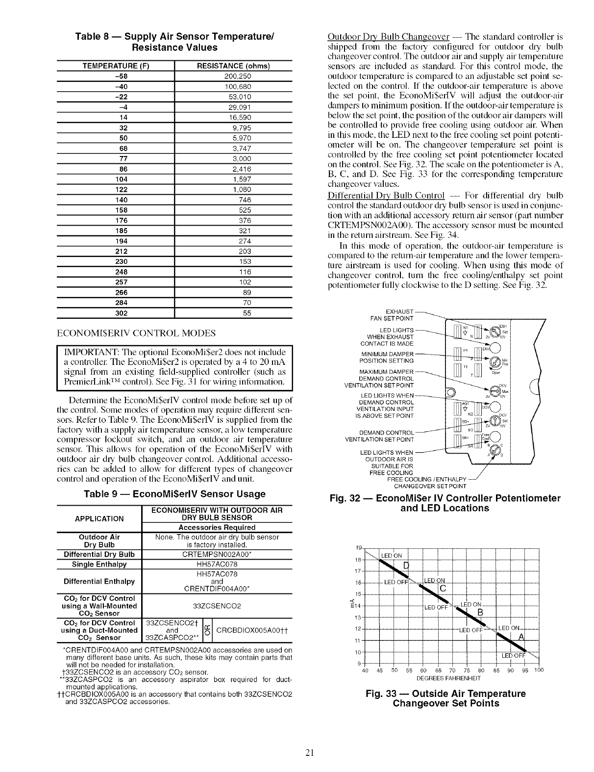
Table 8 -- Supply Air Sensor Temperature/
Resistance Values
TEMPERATURE(F) RESISTANCE(ohms)
-58 200,250
-40 100,680
-22 53,010
-4 29,091
14 15,590
32 9,795
50 5,970
68 3,747
77 3,000
86 2,416
104 1,597
122 1,080
140 746
158 525
176 376
185 321
194 274
212 203
230 153
248 115
257 102
266 89
284 70
302 55
ECONOM[$ERIV CONTROL MODES
IIMPORTANT: The optional EconoMi$er2 does not include
a controllel: The EconoMiSer2 is operated by a 4 to 20 mA
signal from an existing field-supplied controller (such as
PremierLink TM control). See Fig. 31 for wiling infonnation.
Detennine the EconoMiSerlV control mode before set up of
the control. Some modes of operation may lequire diffelent sen-
sors. Refer to Table 9. The EconoMi$erIV is supplied from the
factory with a supply air temperature sensor, a low temperature
complessor lockout switch, and an outdoor air temperature
sensol: This allows for operation of the EconoMi$erIV with
outdoor air dry bulb changeover control. Additional accesso-
ries can be added to allow for different types of changeover
control and operation of the EconoMiSerIV and unit.
Table 9 -- EconoMiSerlV Sensor Usage
APPLICATION
Outdoor Air
Dry Bulb
Differential Dry Bulb
Single Enthalpy
Differential Enthalpy
CO2 for DCV Control
using aWall-Mounted
CO2 Sensor
CO2 for DCV Control
using a Duct-Mounted
CO2 Sensor
ECONOMISERIV WITH OUTDOOR AIR
DRY BULB SENSOR
Accessories Required
None. The outdoor air dry bulb sensor
is factory installed.
CRTEMPSN002A00*
HH57AC078
HH57AC078
and
CRENTDIF004A00*
33ZCSENCO2
33ZCSENCO2t
and _ CRCBDIOX005A00tt
33ZCASPCO2**
*CRENTDIF004A00 and CRTEMPSN002A00 accessories are used on
many different base units. As such, these kits may contain parts that
will not be needed for installation.
1-33ZCSENCO2 is an accessory CO2 sensor.
**33ZCASPCO2 is an accessory aspirator box required for duct-
mounted applications.
1-1-CRCBDiOX005A00 is an accessory that contains both 33ZCSENCO2
and 33ZCASPCO2 accessories.
Outdoor Dly Bulb Changeover -- The standard controller is
shipped from the facto qconfigured for outdoor @ bulb
changeover control. The outdoor air and supply air temperature
sensors ;ue included as stan&ud. For this control mode, the
outdoor temperature is comptu'ed to an adjustable set point se-
lected on the control. [f the outdoor-air temperature is above
the set point, the EconoMiSerIV will adjust the outdoor-air
dampers to minimum position. If the outdoor-air temperature is
below the set point, the position of the outdoor air dampers will
be controlled to provide free cooling using outdoor ail: When
in this mode, the LED next to the free cooling set point potenti-
ometer will be on. The changeover temperature set point is
controlled by the flee cooling set point potentiometer located
on the control. See Fig. 32. The sc_de on the potentiometer is A,
B, C, and D. See Fig. 33 for the corresponding temperatme
changeover values.
Differential Dry Bulb Control -- For differential dry bulb
control the standard outdoor @ bulb sensor is used in conjunc-
tion with an additional accessory return air sensor (pall number
CRTEMPSN002A00). The accessory sensor must be mounted
in the return airstream. See Fig. 34.
In this mode of operation, the outdoor-air tempelature is
compared to the return-air temperature and the lower tempera-
ture airstream is used for cooling. When using this mode of
changeover control, turn file free cooling/enthalpy set point
potentiometer fully clockwise to the D setting. See Fig. 32.
FAN SET POINT
LED
WHEN EXHAUST
CONTACT IS MADE
POSITION SETTING
MAXtMt
DEMAND CONTROL
VENTILATION SET POINT
LED LIGHT_
DEMAND CONTROL
VENTILATION INPUT
IS ABOVE SET POINT
VENTILATION SET POINT
LED LIGHTS WHEN
OUTDOOR AIR IS
SUITABLE FOR
FREE COOLING
FREE COOLING /ENTHALPY
CHANGEOVER SET POINT
Fig. 32 -- EconoMi$er IV Controller Potentiometer
and LED Locations
19
18 ''_'+'_ LED _ON
LED ON
16- -- - LED OFF
_14
13
12
11
lO
9
4o 46 50 55
LED ON
LED ON-- --
LED OFF"_
I
65 70 75 80 85 90 95 100
DEGREES FAHRENHEIT
Fig. 33 -- Outside Air Temperature
Changeover Set Points
21
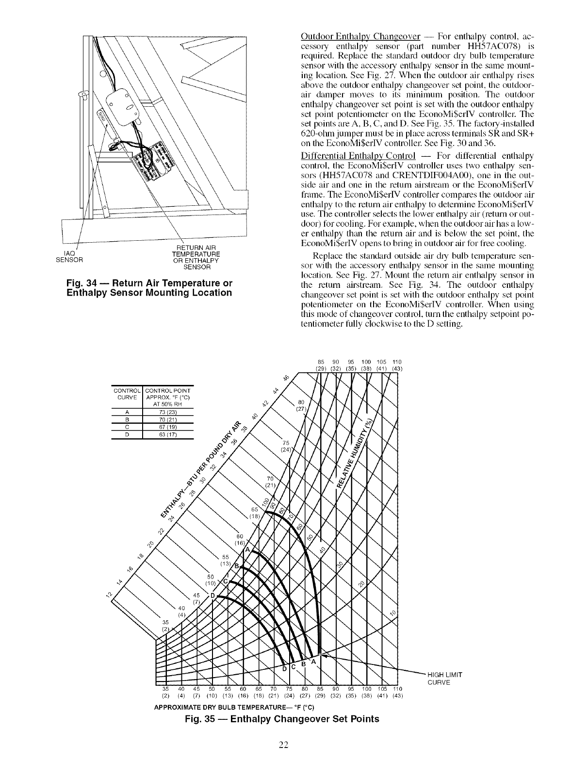
RETURN AIR
IAQ TEMPERATURE
SENSOR OR ENTHALPY
SENSOR
Fig. 34 -- Return Air Temperature or
Enthalpy Sensor Mounting Location
Outdoor Enthalpy Changeover -- For enthalpy control, ac-
cessory enthalpy sensor (p_ut number HH57AC078) is
required. Replace the standard outdoor dry bulb temperature
sensor with the accessory enthalpy sensor in the same mount-
ing location. See Fig. 27. When the outdoor air enthalpy rises
above file outdoor enthalpy changeover set point, file outdoor-
air damper moves to its minimum position. The outdoor
enthalpy changeover set point is set with the outdoor enth_dpy
set point potentiometer on the EconoMiSerlV controllel: The
set points are A, B, C, and I). See Fig. 35. The factory-installed
620-chin jumper must be in place across terminals SR and SR+
on the EconoMiSerIV controllel: See Fig. 30 and 36.
Differential Enthalpy Control -- For differential enth_dpy
control, the EconoMiSerIV controller uses two enthalpy sen-
sors (HH57AC078 and CRENTI)IF004A00), one in the out-
side air and one in the return airstream or the EconoMiSerIV
frame. The EconoMiSerlV controller compmes the outdoor air
enthalpy to file return air enthalpy to determine EconoMi$erIV
use. The controller selects the lower enthalpy air (return or out-
door) for cooling. For example, when the outdoor air has a low-
er enth_dpy than the return air and is below the set point, the
EconoMiSerIV opens to bring in outdoor tfir for free cooling.
Replace the standard outside air dry bulb temperature sen-
sor with the accessory entbalpy sensor in the same mounting
location. See Fig. 27. Mount the return air enthalpy sensor in
the return airstream. See Fig. 34. The outdoor enthalpy
changeover set point is set with the outdoor enthalpy set point
potentiometer on the EconoMiSerlV controller. When using
this mode of changeover control, turn the enthalpy setpoint po-
tentiometer fully clockwise to the D setting.
CONTROL CONTROL POINT
CURVE APPROX. °F (°C)
AT 50% RH
A 73123)
B 70(21)
C 67 {19)
D 63 (17)
85 90 95 100 105 110
(29) (32) (35) (38) (41) (43)
7-,
-.,/
7,,
\
-../
y.,.
\
-./
\
\
)<
\
HIGH LIMIT
CURVE
35 40 45 50 55 60 65 70 75 80 85 90 95 100 105 110
(2) (4) (7) (10) (13) (16) (18) (21) (24) (27) (29) (32) (35) (38) (41) (43)
APPROXIMATE DRY BULB TEMPERATURE-- °F (°C)
Fig. 35 -- Enthalpy Changeover Set Points
22
NOTE: Remove 620-ohm resistor if differential enthalpy sen-
sor is installed.
Indoor Air Quality (IAQ) Sensor Input -- The IAQ input
can be used for demand control ventilation control based on the
level of CO2 measured in the space or mtum air duct.
Mount the accessory IAQ sensor according to manufacturer
specifications. The IAQ sensor should be wired to file AQ and
AQI terminals of file controller Adjust the DCV potentiome-
ters to correspond to file DCV voltage output of the indoor air
qufflity sensor fit the usel;determined set point. See Fig. 37.
If a separate field-supplied transfon3rler is used to power the
IAQ sensor, the sensor must not be grounded or the
EconoMiSerIV control board will be &imaged.
Exhaust Set Point Adjustment -- The exhaust set point will
determine when the exhaust fan runs based on damper position
(if accessory power exhaust is installed). The set point is modi-
fied with the Exhaust Fan Set Point (EXH SET) potentiometel:
See Fig. 32. The set point represents the dm3rlper position above
which the exhaust fan will be turned on. When them is a call
for exhaust, the EconoMiSerIV controller provides a 45 _+ 15
second delay before exhaust fan activation to allow the damp-
ers to open. This delay allows the damper to reach file appro-
priate position to avoid unnecessary fan overload.
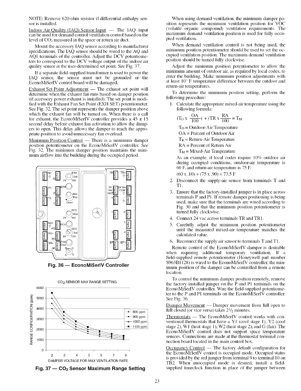
Minimum Position Control -- There is a minimum damper
position potentiometer on the EconoMiSerIV controllel: See
Fig. 32. The minimum dmnper position maintains the mini-
mum airflow into the building during the occupied period.
...........................TR
v'ac DM
EF_ _F1
..../
Fig. 36- EconoMi$erlV Controller
6000
5000
z
_o 4000
rr
---. 3000
Lk
z
oO 2000
IJJ
(5
z 1000
<
rr
CO 2 SENSOR MAX RANGE SETTING
+ 800ppm
+1100 ppm
o
2345678
DAMPER VOLTAGEFOR MAX VENTILATIONRATE
Fig. 37 -- 002 Sensor Maximum Range Setting
When using demand ventilation, the minimum dm3rlper po-
sition represents the minimum ventilation position for VOC
(volatile organic compound) ventilation requirements. The
maximum demand ventilation position is used for fully occu-
pied ventilation.
When demand ventilation control is not being used, the
minimum position potentiometer should be used to set the oc-
cupied ventilation position. The maximum demand ventilation
position should be turned fully clockwise.
Adjust the minimum position potentiometer to allow the
minimum amount of outdoor ail, as required by local codes, to
enter the building. Make minimum position adjustments with
at least 10 ° F temperature difference between file outdoor and
return-air temperatures.
To determine the minimum position setting, perform the
following procedure:
1. Calculate the appropriate mixed-air temperature using the
following formula:
OA RA
(To x l-T0-0- ) + (TR x l-T00- = TM
To = Outdoor-Air Temperature
OA = Percent of Outdoor Air
TR = Return-Air Temperature
RA = Pement of Return Air
TM = Mixed-Air Temperature
As an example, if local codes require 10% outdoor air
during occupied conditions, outdoor-air temperature is
60 E and return-air temperature is 75 E
(60 x. 10) + (75 x .90) = 73.5 F
2. Disconnect the supply-ffir sensor from temlinals T and
TI.
3. Ensure that the factou-installed jumper is in place across
terminals P and Pl. If remote damper positioning is being
used, make sure that the terminals are wired according to
Fig. 30 and that the minimum position potentiometer is
turned fully clockwise.
4. Connect 24 vac across terminals TR and TRI.
5. Carefully adjust the minimum position potentiometer
until the measured mixed-air temperature matches the
calculated vfflue.
6. Reconnect the supply air sensor to terminals T and TI.
Remote control of the EconoMi$erIV damper is desirable
when requiting additional tempora Uventilation, ff a
field-supplied remote potentiometer (Honeywell pfu-t number
$963B1128) is wired to the EconoMi$erIV controllen the min-
imum position of the &unper can be controlled from a remote
location.
To control file minimum damper position remotely, remove
file factou-installed jumper on file P and PI terminals on the
EconoMi$erIV controller Wire the field-supplied potentiome-
ter to the P and PI terminals on the EconoMi$erIV controllen
See Fig. 36.
Damper Movement -- Damper movement from full open to
lull closed (or vice versa) takes 21/2 minutes.
Thermostats -- The EconoMi$erlV control works with con-
ventional thermostats that have a YI (cool stage 1), Y2 (cool
stage 2), WI (heat stage 1), W2 (heat stage 2), and G (fan). The
EconoMi$erIV control does not support space temperatme
sensors. Connections fue made at the themlostat terminal con-
nection board located in file main control box.
Occupancy Control -- The facto Udefault configuration for
the EconoMi$erIV control is occupied mode. Occupied status
is provided by the red jumper from terminal 9 to terminal 10 on
TB2. When unoccupied mode is desired, install a field-
supplied timeclock function in place of the jumper between
23

terminals9and10onTB2.SeeFig.30.Whenthetimeclock
contactsareclosed,theEconoMiSerIVcontrolwillbeinoccu-
piedmode.Whenfiletimeclockcontactsareopen(removing
the24-vsignalfromterminalN),theEconoMiSerIVwillbein
unoccupiedmode.
Demand Controlled Ventilation (DCV) -- When using the
EconoMiSerlV for demand controlled ventilation, there me
some equipment selection criteria which should be considered.
When selecting the heat capacity and cool capacity of the
equipment, the maximum ventilation rate must be evaluated for
design conditions. The maximum dmnper position must be cal-
culated to provide the desired fresh tdl:
Typically file maximum ventilation rate will be about 5 to
10% more than the typical cfm required per peLson, using
normal outside air design criteria.
A proportional anticipatory strategy should be taken with
the following conditions: a zone with a large area, varied occu-
pancy, and equipment that cannot exceed the required ventila-
tion rate tit design conditions. Exceeding the required ventila-
tion rate means the equipment can condition air tit a maximum
ventilation rate that is greater than the required ventilation rate
for maximum occupancy. A proportional-anticipatory strategy
will cause the fresh air supplied to increase as the room CO2
level increases even though the CO2 set point has not been
reached. By the time the CO2 level reaches the set point, the
dmnper will be tit maximum ventilation and should maintain
the set point.
In order to have the CO2 sensor control the economizer
dalnper in this manner, first determine the damper voltage out-
put for minimum or base ventilation. Base ventilation is the
ventilation required to remove contaminants during unoccu-
pied periods. The following equation may be used to determine
the percent of outside-air entering the building for a given
damper position. For best results there should be at least a
10 degree difference in outside and return-air temperatures.
OA RA
(To x l---if6-) + (TR x _ = TM
To = Outdoor-Air Temperature
OA = Percent of Outdoor Air
TR = Return-Air Temperature
RA = Percent of Return Air
TM = Mixed-Air Temperature
Once base ventilation has been determined, set the mini-
mum dmnper position potentiometer to the correct position.
The stone equation can be used to determine the occupied or
maximum ventilation rate to the building. For example, tin out-
put of 3.6 volts to the actuator provides a base ventilation rate
of 5% and an output of 6.7 volts provides the maximum venti-
lation rate of 20% (or base plus 15 cfin per person). Use Fig. 37
to determine the maximum setting of the CO,__sensor For ex-
ample, a 1100 ppm set point relates to a 15 cfln per person de-
sign. Use the 1100 ppm curve on Fig. 37 to find the point when
the CO2 sensor output will be 6.7 volts. Line up the point on the
graph with the left side of the chart to determine that the range
configuration for the CO2 sensor should be 1800 ppm. The
EconoMiSerIV controller will output the 6.7 volts from the
CO,__sensor to the actuator when the CO,_ concentration in the
space is tit 1100 ppm. The DCV set point may be left tit 2 volts
since the CO2 sensor voltage will be ignored by the
EconoMiSerIV controller until it rises above the 3.6 volt setting
of the minimum position potentiometer
Once the fully occupied dmnper position has been deter-
mined, set file maximum dalnper demand control ventilation
potentiometer to this position. Do not set to the maximum posi-
tion as this can result in over-ventilation to the space and poten-
tial high-humidity levels.
CO,_ Sensor Configuration --The CO2 sensor has preset
standard voltage settings that can be selected anytime after the
sensor is powered up. See Table 10.
Use setting 1 or 2 for Carrier equipment. See Table 10.
1. Press Clear and Mode buttons. Hold tit least 5 seconds
until the sensor enters the Edit mode.
2. Press Mode twice. The STDSET Menu will appem:
3. Use the Up/Down button to select the preset numbel: See
Table 10.
4. Press Enter to lock in the selection.
5. Press Mode to exit and resume normal operation.
The custom settings of the CO2 sensor can be changed any-
time after the sensor is energized. Follow the steps below to
change the non-stanchrd settings:
1. Press Clear and Mode buttons. Hold tit least 5 seconds
until the sensor enters the Edit mode.
2. Press Mode twice. The STDSET Menu will appem:
3. Use the Up/Down button to toggle to the NONSTD menu
and press Entel:
4. Use the Up/Down button to toggle through each of the
nine variables, starting with Altitude, until the desired set-
ting is reached.
5. Press Mode to move through the variables.
6. Press Enter to lock in the selection, then press Mode to
continue to the next vmiable.
Dehumidification of Fresh Air with DCV Control -- Infor-
mation from ASHRAE indicates that the largest humidity load
on any zone is the fresh air introduced. For some applications,
a field-supplied energy recovery unit can be added to reduce
the moisture content of the fresh tdr being brought into the
building when the enthalpy is high. In most cases, the normal
heating and cooling processes are more than adequate to re-
move the humidity loads for most commercial applications.
If normal rooftop heating and cooling operation is not ade-
quate for the outdoor humidity level, an energy recovery unit
and/or a dehumidification option should be considered.
24
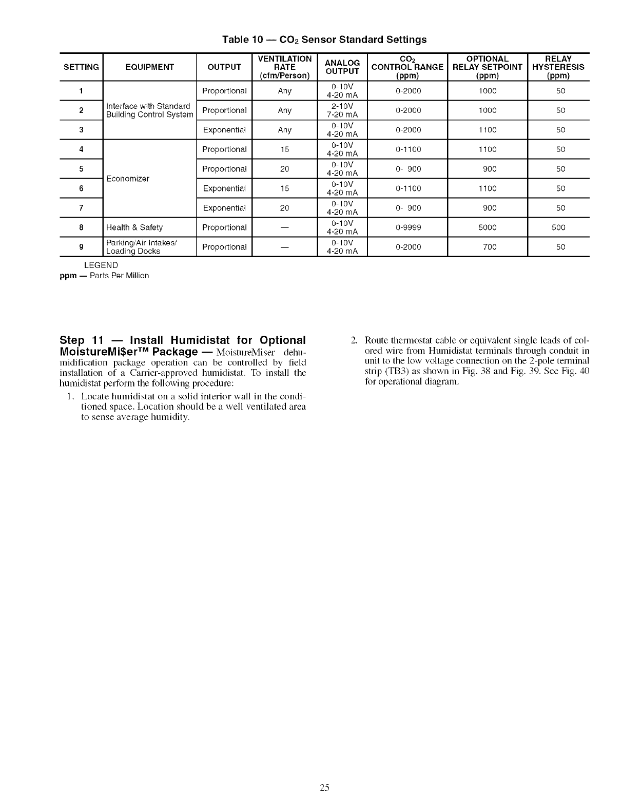
Table 10 -- 002 Sensor Standard Settings
ANALOG
OUTPUT
SETTING
1
2
3
4
5
6
7
8
EQUIPMENT
Interface with Standard
Building Control System
Economizer
Health & Safety
9Parking/Air Intakes/
Loading Docks
LEGEND
ppm -- Parts Per Million
OUTPUT
Proportional
Proportional
Exponential
Proportional
Proportional
Exponential
Exponential
Proportional
Proportional
VENTILATION
RATE
(cfm/Pereon)
Any
Any
Any
15
20
15
20
0-10V
4-20 mA
2-10V
7-20 mA
0-10V
4-20 mA
0-10V
4-20 mA
0-10V
4-20 mA
0-10V
4-20 mA
0-10V
4-20 mA
0-10V
4-20 mA
0-10V
4-20 mA
002
CONTROLRANGE
(ppm)
0-2000
0-2000
0-2000
0-1100
0- 900
0-1100
0- 900
0-9999
0-2000
OPTIONAL
RELAY SETPOINT
(ppm)
1000
1000
1100
1100
900
1100
900
5000
700
RELAY
HYSTERESIS
(ppm)
50
50
50
50
50
50
50
50O
50
Step 11 -- Install Humidistat for Optional
MoistureMi$er TM Package-- MoistureMiser dehu-
midification package operation can be controlled by field
installation of a Carrier-approved hurnidistat. To install tile
humidistat perform tile following procedure:
1. Locate humidistat on a solid interior wall in the condi-
tioned space. Location should be a well ventilated area
to sense average humidity.
Route therlnostat cable or equivalent single leads of col-
ored wire fiom Humidistat terminals through conduit in
unit to the low voltage connection on the 2-pole terminal
strip (TB3) as shown in Fig. 38 and Fig. 39. See Fig. 40
for operation_d diagram.
25
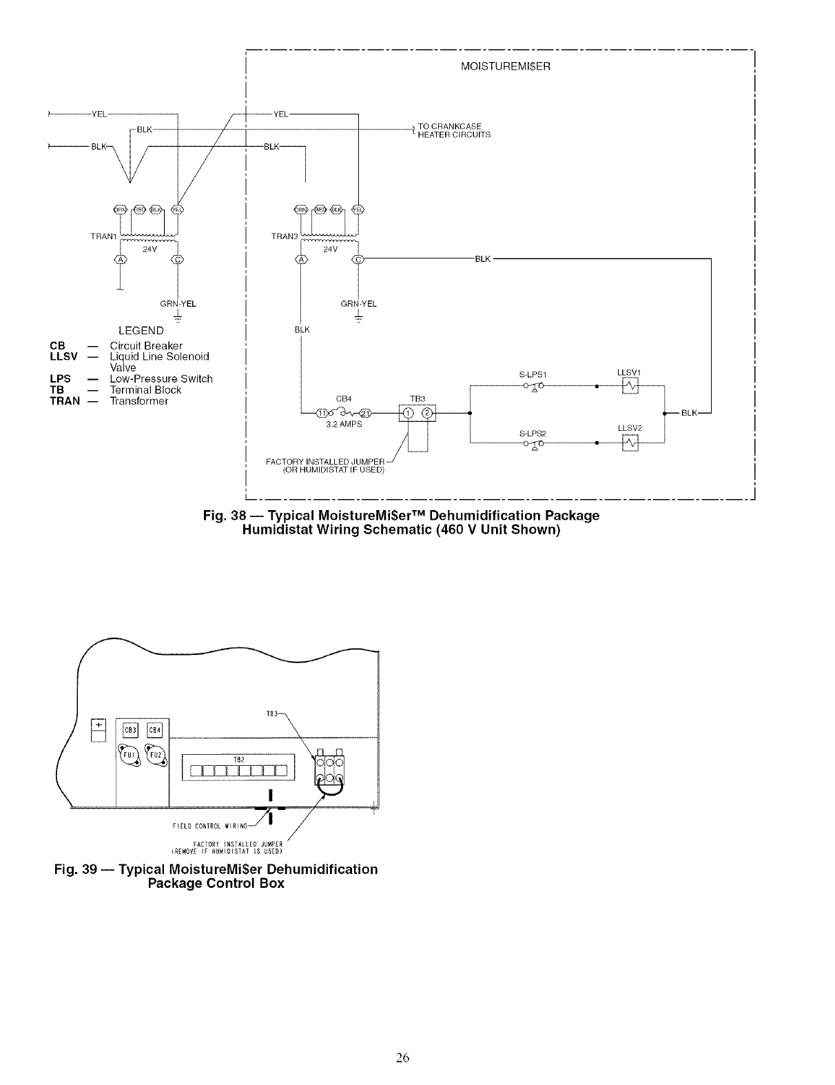
MOISTUREMI$ER
_----_YEL
BLK
_'_ BLK_,
CB --
LLSV --
LPS --
TB --
TRAN --
TRAN1_
GRN-YEL
±
LEGEND
Circuit Breaker
Liquid Line Solenoid
Valve
Low-Pressure Switch
Terminal Block
Transformer
TO CRANKCASE
/ HEATER CIRCUITS
EL "BLK
BLK
S-LPS1
CB4 TB3
3.2 AMPS S LPS2
FACTOR
(OR HUMIDISTAT IF USED)
LLSV1
•• LLeV2_ BLK--
Fig. 38 -- Typical MoistureMi$er TM Dehumidification Package
Humidistat Wiring Schematic (460 V Unit Shown)
FACTORY INSTALLED JUMPER
(R[MOVE _F HUNIOISTAT IS USZD)
Fig. 39 -- Typical MoistureMiSer Dehumidification
Package Control Box
26
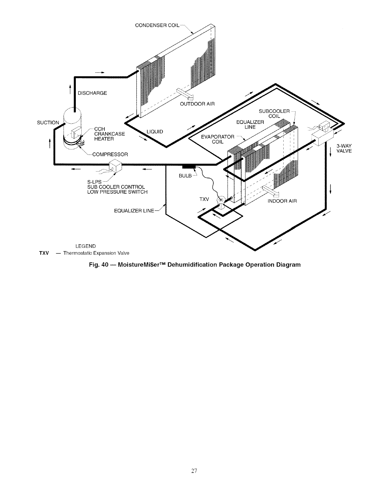
CONDENSER COIL ,
SUCTION
l DISCHARGE
/
_CCHCRANKCASE
HEATER
\--COMPRESSOR
LIQUID
OUTDOOR AiR
EVAPORATOR
COIL
EQUALIZER
LINE
COIL
3-WAY
VALVE
TXV
BULB
S-LPS -j I
SUB COOLER CONTROL
LOW PRESSURE SWITCH I
_oo_z_,_e_!_L._xv
/
/
INDOOR AIR
LEGEND
-- Thermostatic Expansion Valve
Fig. 40 -- MoistureMi$er TM Dehumidification Package Operation Diagram
27
START-UP
Use the following information and St_ut-Up Checklist on
page CL-I to check out unit PRIOR to start-up.
Unit Preparation -- Check that unit has been installed in
accordance with these installation instructions and all applica-
ble codes.
COMPRESSOR MOUNTING -- Compressors are internal-
ly spring mounted. Do not loosen or remove compressor hold-
down bolts.
REFRIGERANT SERVICE PORTS -- Each refrigerant sys-
tem has a total of 3 Schlader-type service gage ports. One port
is located on the suction line, one on the compressor discharge
line, and one on the liquid line. In addition Schmder-type
v;dves are located underneath the low-pressure switches. Be
sure that caps on the ports are tight.
COMPRESSOR ROTATION -- It is important to be certain
the compressors are rotating in the proper direction. To deter-
mine whether or not compressors tue rotating in the proper
direction:
1. Connect service gages to suction and discharge pressure
fittings.
2. Energize the compressoc
3. The suction pressure should drop and the discharge pres-
sure should rise, as is normal on any start-up.
If the suction pressure does not drop and the discharge pres-
sure does not rise to normal levels:
1. Note that the evaporator fan is probably _dso rotating in
the wrong direction.
2. Turn off power to the unit.
3. Reverse any two of the incoming power leads.
4. Turn on power to the compressol:
The suction and discharge pressure levels should now move
to their normal start-up levels.
NOTE: When compressors are rotating in the wrong direction,
the unit will have increased noise levels and will not provide
heating and cooling.
After a few minutes of reverse operation, the scroll com-
pressor internal overload protection will open, which will acti-
vate the unit's lockout and requires a manual reset. Reset is ac-
complished by turning the thermostat on and off.
INTERNAL WIRING- Check all electric_d connections in
unit control boxes; tighten as required.
CRANKCASE HEATER(S)--Heater(s) is energized as
long as there is power to unit and compressor is not operating.
IMPORTANT: Unit power must be on for 24 hom_ prior
to start-up. Otherwise, &image to compressor may result.
EVAPORATOR FAN- Fan belt and variable pulleys are
factory installed. Remove tape from the fan pulley. See
Tables 11- 13 for fan performance &_ta. Be sure that fans rotate
in the proper direction. See Table 14 for air quantity limits. See
Tables 15 and 16 for static pressure infommtion for accessories
and options. See Table 17 for fan rpm at various fan motor pul-
ley settings. See Table 18 for evaporator-fan motor specifica-
tions. To alter fan performance, see Evaporator Fan Perfor-
mance Adjustment section, page 35.
CONDENSER FANS AND MOTORS -- Condenser fans
and motors are factory set. Refer to Condenser-Fan Adjustment
section (page 36) as lequired. Be sure that fans rotate in the
conect direction.
RETURN-AIR FILTERS -- Check that correct filtel_ are in-
stalled in filter tracks. See Table 1. Do not operate unit without
return-air filters.
28
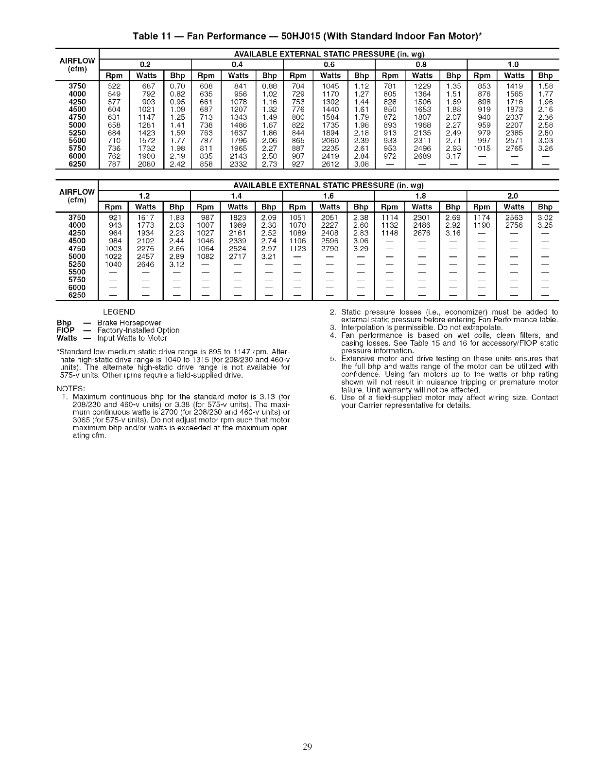
AIRFLOW
(cfm)
375O
4000
4250
4500
4750
5000
5250
5500
5750
6000
6250
Table 11 -- Fan Performance- 50HJ015 (With Standard Indoor Fan Motor)*
AVAILABLE EXTERNAL STATIC PRESSURE (in. wg)
0.2 0.4 0.6 0.8 1.0
Rpm Watts Bhp Rpm Watts Bhp Rpm Watts Bhp Rpm Watts Bhp Rpm Watts Bhp
522 687 0,70 608 841 0.88 704 1045 1.12 781 1229 1.35 853 1419 1.58
549 792 0,82 635 956 1.02 729 1170 1.27 805 1364 1.51 876 1565 1.77
577 903 0.95 661 1078 1.16 753 1302 1.44 828 1506 1.69 898 1716 1.96
604 1021 1.09 687 1207 1.32 776 1440 1.61 850 1653 1.88 919 1873 2.16
631 1147 1.25 713 1343 1.49 800 1584 1.79 872 1807 2.07 940 2037 2.36
658 1281 1,41 738 1486 1.67 822 1735 1.98 893 1968 2.27 959 2207 2.58
684 1423 1.59 763 1637 1.86 844 1894 2.18 913 2135 2.49 979 2385 2.80
710 1572 1.77 787 1796 2.06 865 2060 2.39 933 2311 2.71 997 2571 3.03
736 1732 1.98 811 1965 2.27 887 2235 2.61 953 2496 2.93 1015 2765 3.26
762 1900 2,19 835 2143 2.50 907 2419 2,84 972 2689 3.17 -- -- --
787 2080 2,42 858 2332 2.73 927 2612 3.08 ......
AIRFLOW
(cfm)
3750
4000
4250
4500
4750
5000
5250
5500
5750
6000
6250
AVAILABLE EXTERNAL STATIC PRESSURE (in. wg)
1.2 1.4 1.6 1.8 2.0
Rpm Watts Bhp Rpm Watts Bhp Rpm Watts Bhp Rpm Watts Bhp Rpm Watts Bhp
921 1617 1.83 987 1823 2.09 1051 2051 2.38 1114 2301 2.69 1174 2563 3.02
943 1773 2.03 1007 1989 2.30 1070 2227 2.60 1132 2486 2.92 1190 2756 3.25
964 1934 2.23 1027 2161 2.52 1089 2408 2.83 1148 2676 3.16 -- -- --
984 2102 2.44 1046 2339 2.74 1106 2596 3.06 ......
1003 2276 2.66 1064 2524 2.97 1123 2790 3.29 ......
1022 2457 2.89 1082 2717 3.21 .........
1040 2646 3.12 ............
LEGEND
Bhp -- Brake Horsepower
FlOP -- Factory-Installed Option
Watts -- Input Watts to Motor
*Standard low-medium static drive range is 895 to 1147 rpm. Alter-
nate high-static drive range is 1040 to 1315 (for 208/230 and 460-v
units). The alternate high-static drive range is not available for
575-v units. Other rpms require a field-supplied drive.
NOTES:
1. Maximum continuous bhp for the standard motor is 3.13 (for
208/230 and 460-v units) or 3.38 (for 575-v units). The maxi-
mum continuous watts is 2700 (for 208/230 and 460-v units) or
3065 (for 575-v units). Do not adjust motor rpm such that motor
maximum bhp and/or watts is exceeded at the maximum oper-
ating cfm.
2. Static pressure losses (i.e., economizer) must be added to
external static pressure before entering Fan Performance table.
3. Interpolation is permissible. Do not extrapolate.
4. Fan performance is based on wet coils, clean filters, and
casing losses. See Table 15 and 16 for accessory/FlOP static
pressure information.
5. Extensive motor and drive testing on these units ensures that
the full bhp and watts range of the motor can be utilized with
confidence. Using fan motors up to the watts or bhp rating
shown will not result in nuisance tripping or premature motor
failure. Unit warranty will not be affected.
6. Use of a field-supplied motor may affect wiring size. Contact
your Carrier representative for details.
29
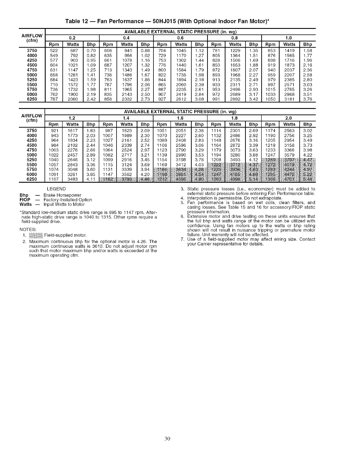
AIRFLOW
(cfm)
375O
4000
4250
4500
4750
5000
5250
5500
5750
6000
6250
Table 12 -- Fan Performance -- 50HJ015 (With Optional Indoor Fan Motor)*
AVAILABLE EXTERNAL STATIC PRESSURE (in. wg)
0.2 0.4 0.6 0.8 1.0
Rpm Watts Bhp Rpm Watts Bhp Rpm Watts Bhp Rpm Watts Bhp Rpm Watts Bhp
522 687 0.70 608 841 0.88 704 1045 1.12 781 1229 1.35 853 1419 1.58
549 792 0,82 635 956 1.02 729 1170 1.27 805 1364 1.51 876 1565 1.77
577 903 0,95 661 1078 1,16 753 1302 1,44 828 1506 1,69 898 1716 1,96
604 1021 1,09 687 1207 1,32 776 1440 1,61 850 1653 1,88 919 1873 2,16
631 1147 1.25 713 1343 1.49 800 1584 1.79 872 1807 2.07 940 2037 2.36
658 1281 1,41 738 1486 1,67 822 1735 1,98 893 1968 2,27 959 2207 2,58
684 1423 1,59 763 1637 1,86 844 1894 2,18 913 2135 2,49 979 2385 2,80
710 1572 1,77 787 1796 2,06 865 2060 2,39 933 2311 2,71 997 2571 3,03
736 1732 1,98 811 1965 2,27 887 2235 2,61 953 2496 2,93 1015 2765 3,26
762 1900 2,19 835 2143 2,50 907 2419 2,84 972 2689 3,17 1033 2968 3,51
787 2080 2,42 858 2332 2,73 927 2612 3.08 991 2892 3.42 1050 3181 3.76
AVAILABLE EXTERNAL STATIC PRESSURE (in. wg)
AIRFLOW
(cfm) 1.2 1.4 1.6 1.8
Rpm Watts Bhp Rpm Watts Bhp Rpm Watts Bhp Rpm Watts
3750 921 1617 1.83 987 1823 2.09 1051 2051 2.38 1114 2301
4000 943 1773 2.03 1007 1989 2.30 1070 2227 2.60 1132 2486
4250 964 1934 2.23 1027 2161 2.52 1089 2408 2.83 1148 2676
4500 984 2102 2.44 1046 2339 2.74 1106 2596 3.06 1164 2872
4750 1003 2276 2,66 1064 2524 2,97 1123 2790 3,29 1179 3073
5000 1022 2457 2,89 1082 2717 3,21 1139 2990 3,53 1194 3280
5250 1040 2646 3,12 1099 2916 3,45 1154 3198 3,78 1208 3493
5500 1057 2843 3,36 1115 3124 3,69 1169 3412 4,03 /_',f2 37 _;!2
5750 1074 3048 3.60 1131 3339 3.94 84 2; 3,9_ !
6000 1091 3261 3.85 1147 3562 4,20 i i i2, _-165
6250 1107 3483 4.11 _;2 _ i_ _0:4398
2.0
Bhp Rpm Watts Bhp
2.69 1174 2563 3.02
2.92 1190 2756 3.25
3.16 1205 2954 3.49
3.39 1219 3158 3,73
3.63 1233 3366 3.98
3.88 1247 3579 4.22
4.12 _259 8799 ;!47
NN N_ ? 48....
LEGEND
Bhp -- Brake Horsepower
FlOP -- Factory-Installed Option
Watts -- Input Watts to Motor
*Standard low-medium static drive range is 895 to 1147 rpm. Alter-
nate high-static drive range is 1040 to 1315. Other rpms require a
field-supplied drive.
NOTES:
1. Field-supplied motor.
2. Maximum continuous bhp for the optional motor is 4.26. The
maximum continuous watts is 3610. Do not adjust motor rpm
such that motor maximum bhp and/or watts is exceeded at the
maximum operating cfm.
3. Static pressure losses (i.e., economizer) must be added to
external static pressure before entering Fan Performance table.
4. Interpolation is permissible. Do not extrapolate.
5. Fan performance is based on wet coils, clean filters, and
casing losses. See Table 15 and 16 for accessory/FlOP static
pressure information.
6. Extensive motor and drive testing on these units ensures that
the full bhp and watts range of the motor can be utilized with
confidence. Using fan motors up to the watts or bhp rating
shown will not result in nuisance tripping or premature motor
failure. Unit warranty will not be affected.
7. Use of a field-supplied motor may affect wiring size. Contact
your Carrier representative for details.
.30
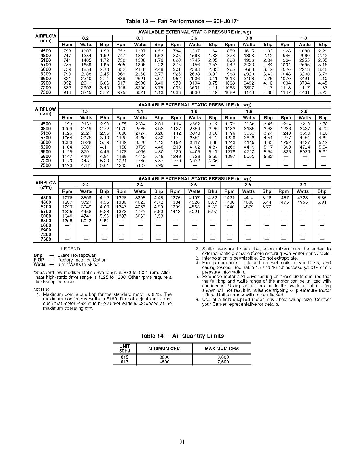
AIRFLOW
(cfm)
4500
4800
5100
5700
6000
6300
6600
6900
7200
7500
Table 13- Fan Performance- 50HJ017"
AVAILABLE EXTERNAL STATIC PRESSURE (in. wg)
0.2 0.4 0.6 0.8 1.0
Rpm Watts Bhp Rpm Watts Bhp Rpm Watts Bhp Rpm Watts Bhp Rpm Watts Bhp
753 1307 1.53 753 1307 1.53 784 1397 1.64 859 1635 1.92 928 1880 2.20
747 1384 1.62 747 1384 1.62 806 1563 1.83 878 1808 2.12 946 2060 2.42
741 1465 1.72 752 1500 1.76 828 1745 2.05 898 1996 2.34 964 2255 2.65
735 1659 1.95 805 1895 2.22 876 2156 2.53 942 2423 2.84 1004 2696 3.16
759 1854 2.18 832 2118 2.48 901 2388 2.80 965 2663 3.12 1026 2943 3.45
790 2088 2.45 860 2360 2.77 926 2638 3.09 988 2920 3.43 1048 3208 3.76
821 2340 2.74 888 2621 3.07 952 2906 3.41 1013 3196 3.75 1070 3491 4.10
852 2611 3.06 917 2900 3.40 979 3194 3.75 1038 3492 4.10 1094 3794 4.45
883 2903 3.40 946 3200 3.75 1006 3501 4.11 1063 3807 4.47 1118 4117 4.83
914 3216 3.77 975 3521 4.13 1033 3830 4.49 1089 4143 4.86 1142 4461 5.23
AIRFLOW
(cfm)
4500
4800
5100
5700
6000
6300
6600
6900
7200
7500
AVAILABLE EXTERNAL STATIC PRESSURE (in. wg)
1.2 1.4 1.6 1.8 2.0
Rpm Watts Bhp Rpm Watts Bhp Rpm Watts Bhp Rpm Watts Bhp Rpm Watts Bhp
993 2133 2.50 1055 2394 2.81 1114 2662 3.12 1170 2938 3.45 1224 3220 3.78
1009 2319 2.72 1070 2585 3.03 1127 2859 3.35 1183 3139 3.68 1236 3427 4.02
1026 2521 2.96 1086 2794 3.28 1142 3073 3.60 1196 3359 3.94 1248 3650 4.28
1064 2975 3.49 1120 3260 3.82 1174 3551 4.17 1226 3848 4.51 1277 4151 4.87
1083 3228 3.79 1139 3520 4.13 1192 3817 4.48 1243 4119 4.83 1292 4427 5.19
1104 3501 4.11 1158 3799 4.46 1210 4102 4.81 1260 4410 5.17 1309 4724 5.54
1126 3791 4.45 1178 4095 4.80 1229 4405 5.17 1278 4720 5.54 1326 5039 5.91
1147 4101 4.81 1199 4412 5.18 1249 4728 5.55 1297 5050 5.92 -- -- --
1170 4431 5.20 1221 4749 5.57 1270 5072 5.95 ......
1193 4781 5.61 1243 5107 5.99 .........
AIRFLOW
(cfm)
4500
4800
5100
5700
6000
6300
6600
6900
7200
7500
AVAILABLE EXTERNAL STATIC PRESSURE (in. wg)
2.2 2.4 2.6 2.8 3.0
Rpm Watts Bhp Rpm Watts Bhp Rpm Watts Bhp Rpm Watts Bhp Rpm Watts Bhp
1276 3509 4.12 1326 3805 4.46 1375 4107 4.82 1421 4414 5.18 1467 4728 5.55
1287 3721 4.36 1336 4020 4.72 1384 4326 5.07 1430 4638 5.44 1475 4955 5.81
1299 3949 4.63 1347 4253 4.99 1395 4563 5.35 1440 4879 5.72 -- -- --
1325 4458 5.23 1373 4772 5.60 1418 5091 5.97 ......
1340 4741 5.56 1387 5060 5.93 .........
1356 5043 5.91 ............
LEGEND
Bhp -- Brake Horsepower
FlOP -- Factory-Installed Option
Watts -- Input Watts to Motor
*Standard low-medium static drive range is 873 to 1021 rpm. Alter-
nate high-static drive range is 1026 to 1200. Other rpms require a
field-supplied drive.
NOTES:
1. Maximum continuous bhp for the standard motor is 6.13. The
maximum continuous watts is 5180. Do not adjust motor rpm
such that motor maximum bhp and/or watts is exceeded at the
maximum operating cfm.
2. Static pressure losses (i.e., economizer) must be added to
external static pressure before entering Fan Performance table.
3. Interpolation is permissible. Do not extrapolate.
4. Fan performance is based on wet coils, clean filters, and
casing losses. See Table 15 and 16 for accessory/FlOP static
pressure information.
5. Extensive motor and drive testing on these units ensures that
the full bhp and watts range of the motor can be utilized with
confidence. Using fan motors up to the watts or bhp rating
shown will not result in nuisance tripping or premature motor
failure. Unit warranty will not be affected.
6. Use of a field-supplied motor may affect wiring size. Contact
your Carrier representative for details.
Table 14- Air Quantity Limits
UNIT MINIMUM CFM
50HJ
015 3600
017 4500
MAXIMUM CFM
6,000
7,500
3!

Table 15 -- Accessory/FlOP Static Pressure (in. wg)
UNIT
50HJ
015, 017
HEATER
RATED
VOLTAGE*
208/240-3-60
480-3-60
575-3-60
CFM
3,750
4,000
5,000
6,000
7,200
7,500
3,750
4,000
5,000
6,000
7,200
7,500
3,750
4,000
5,000
6,000
7,200
7,500
0.05 (14/19, 26/34)
0.05 (14/19, 26/34)
0.07 (14/19, 26/34)
0.09 (14/19, 26/34)
0.11 (14/19, 26/34)
0.12 (14/19, 26/34)
0.05 (16, 32)
0.05 (16, 32)
0.07 (16, 32)
0.09 (15, 32)
0.11 (15, 32)
0.12 (15, 32)
ELECTRIC HEATERS
PRESSURE DROP
(kW)
0.06 (42/56)
0.06 (42/56)
0.08 (42/56)
0.12 (42/56)
0.16 (42/56)
0.17 (42/56)
0.06 (55)
0.06 (55)
0.08 (85)
0.12 (55)
0.16 (85)
0.17 (55)
0.06 (37)
0.06 (37)
0.08 (37)
0.12 (37)
0.16 (37)
0.17 (37)
LEGEND
0.07 (56/75)
0.07 (56/75)
0.10 (56/75)
0.15 (56/75)
0.20 (56/75)
0.21 (66/76)
0.07(80)
0.07(80)
0.10(80)
0.15 (80)
0.20 (80)
0.21 (80)
ECONOMIZER
PRESSURE
DROP
0.03
0.04
0.05
0.07
0.09
0.10
0.03
0.04
0.05
0.07
0.09
0.10
0.03
0.03
0.05
0.07
0.09
0.10
FlOP -- Factory-Installed Option 3.
*There are no electric heaters available for 017 676-v units.
NOTES:
1. Heaters are rated at 240 v, 480 v, and 676 v.
2. The factory assembled horizontal adapter substantially
improves fan performance.
The static pressure must be added to external static pressure.
The sum and the evaporator entering-air cfm should then be
used in conjunction with the Fan Performance table to deter-
mine blower rpm, bhp, and watts.
Table 16- MoistureMi$er TM Dehumidification
Package Static Pressure Drop (in. wg)
UNIT SIZE UNIT NOMINAL CFM PER TON
50HJ TONS 300 400 500
015 12 .026 .045 .071
017 15 .040 .071 .111
Table 17 -- Fan Rpm at Motor Pulley Settings*
50HJ (No. Turns Open) 01/2 1 11/2 2 21/2 3 31/2
015 (208/230, 460, 575 v)t 1147 1124 1101 1078 1055 1032 1010 987
015 (208/230, 460 v)** 1315 1292 1269 1248 1223 1200 1178 1155
017t tt 1-1- tt 1-1- 1021 1002 984 965
017"* tt tf tt tf 1200 1178 1156 1134
*Approximate fan rpm shown.
tlndicates standard drive package.
**Indicates alternate drive package.
ttDue to belt and pulley style, pulley cannot be set to this number of turns open.
441/2 5 51/2 6
964 941 918 895 tt
1132 1109 1086 1063 1040
947 928 910 891 873
1112 1091 1069 1047 1025
Table 18- Evaporator Fan Motor Specifications
UNIT NOMINAL MAX EFE MAX MAX MAX
50HJ HP VOLTAGE WATTS % BHP BkW AMPS
015 2.9 208 2700 85.8 3.13 2.34 9.46
(Standard 2.9 230 2700 85.8 3.13 2.34 8.6
2.9 460 2700 85.8 3.13 2.34 4.3
Motor) 3 575 3065 81.7 3.38 2.53 3.9
015 3.7 208 3610 85.8 4.26 3.18 10.5
(Optional 3.7 230 3610 85.8 4.26 3.18 10.5
Motor) 3.7 460 3610 85.8 4.26 3.18 4.8
5 208 5180 87.5 6.13 4.57 15.8
017 5 230 5180 87.5 6.13 4.57 15.8
5 460 5180 87.5 6.13 4.57 7.9
5 575 5180 87.5 6.13 4.57 6.0
LEGEND
BHP -- Brake Horsepower
32
Operating Sequence
COOLING. UNITS WITHOUT ECONOMIZER --When
thermostat calls for cooling, termimds G and YI ale energized.
The indoor (evaporator) fan contactor (IFC), outdoor fan contac-
tot (OFC), and compressor contactor no. 1 (CI) m'e energized
and evaporator-fan motol: condenser fans and compressor no. 1
stall. The condenser-fan motors run continuously while unit is
cooling. If the thermostat calls for a second stage of cooling by
energizing Y2, compressor contactor no. 2 (C2) is energized and
compressor no. 2 starts.
HEATING. UNITS WITHOUT ECONOMIZER (If Optional
or Accessory Heater is Installed) --Upon a call for heating
through terminal WI, IFC and heater contactor no. 1 (HCI) are
energized. On units equipped for 2 stages of heat, when addi-
tional heat is needed HC2 is energized through W2.
COOLING. UNITS WITH ECONOMISERIV --When free
cooling is not available, the compressors will be controlled by
the zone themlostat. When free cooling is available, the
outdoor-air &unper is modulated by the EconoMiSeriv control
to provide a 50 to 55 F supply-air temperature into the zone. As
the supply-air temperature fluctuates above 55 or below 50 IF.
the dampel.'s will be modulated (open or close) to bring the sup-
ply-air temperature back within set point limits.
For EconoMiSerIV operation, there must be a thermostat
call for the fan (G). This will move the damper to its minimum
position during the occupied mode.
Above 50 F supply-air temperature, the dmnpers will modu-
late from 100% open to the minimum open position. From 50 F
to 45 F supply-air temperature, the cktmpers will maintain at
the minimum open position. Below 45 F the dampers will be
completely shut. As the supply-air temperature rises, the damp-
ers will come back open to the minimum open position once
the supply-air temperature rises to 48 E
If optional power exhaust is inst_dled, as the outdoor-air
damper opens and closes, the power exhaust fans will be ener-
gized and deenergized.
If field-installed accessory CO2 sensors are connected to the
EconoMiSer IV control, a demand controlled ventilation strate-
gy will begin to operate. As the CO,_ level in the zone increases
above the CO2 set point, the minimum position of the &tmper
will be increased proportionally. As the CO2 level decreases
because of the increase in fresh all: the outdoor-air damper will
be proportionally closed. Dmnper position will follow the high-
er demand condition from DCV mode or free cooling mode.
Damper movement from full closed to full open (or vice
vel.sa) will take between 11/2and 21/2 minutes.
If free cooling can be used as determined from the appropri-
ate changeover command (switch, diy bulb, enthalpy curve,
differential dry bulb, or differential enthalpy), a call for cooling
(YI closes at the thermostat) will cause the control to modulate
the &tmpel.s open to maintain the supply air temperature set
point at 50 to 55 E
As the supply-air temperature diops below the set point
range of 50 to 55 E the control will modulate the outdoor-air
dampers closed to maintain the proper supply-air temperature.
HEATING, UNITS WITH ECONOMISERIV -- When the
room temperature calls for heat, the heating controls are ener-
gized as described in the Heating, Units Without Economizer
section. When the indoor fan is energized, the economizer
damper moves to the minimum position. When the indoor fan
is off. the economizer dmnper is fully closed.
COOLING. UNITS WITH ECONOMISER2, PREMIER-
LINK TM CONTROL AND A THERMOSTAT -- When free
cooling is not available, the complessors will be controlled by
the PremierLink control in response to the YI and Y2 inputs
from the thermostat.
The PremierLink control will use the following information
to determine if free cooling is available:
• Indoor fan has been on for at least 30 seconds.
• The SPT. SAT. and OAT inputs must have valid readings.
• OAT must be less than 75 E
• OAT must be less than SPT.
• Enthalpy must be LOW (may be jumpered if an enthalpy
sensor not available).
• Economizer position is NOT forced.
Pre-cooling occurs when the is no c_dl from the thermostat
except G Pre-cooling is defined as the economizer modulates
to provide 70 F supply all:
When free cooling is available the PremierLink control will
control the compressors, energize the reversing valve(s) and
economizer to provide a supply-air temperature determined to
meet the YI and Y2 calls from the thermostat using the follow-
ing three routines. The three control routines are based on OAT.
The 3 routines are based on OAT where:
SASP = Supply Air Set Point
DXCTLO = Direct Expansion Cooling Lockout Set Point
PID = Proportional Integral
Routine 1 (OAT < DXCTLO)
• YI energized - economizer maintains a SASP =
(SATLOI + 3).
• Y2 energized - economizer maintains a SASP =
(SATLO2 + 3).
Routine 2 (DXCTLO < OAT < 68 F)
• If only YI energized, the economizer maintains a SASP
= (SATLOI + 3).
• If SAT > SASP + 5 and economizer position > 80%,
economizer will go to minimum position for 3 minutes or
until SAT > 68 E
• First stage of mechanical cooling will be energized.
• Integrator resets.
• Economizer opens again and controls to current SASP
after stage one on for 90 seconds.
• With YI and Y2 energized economizer maintains an
SASP = SATLO2 + 3.
• If SAT > SASP + 5 and economizer position >80%,
economizer will go to minimum position for 3 minutes or
until SAT > 68 E
• If compressor one is on then second stage of mechanical
cooling will be energized. Otherwise the first stage will
be energized.
• Integrator resets.
• Economizer opens again and controls to SASP after
stage one on for 90 seconds.
Routine 3 (OAT > 68)
• Economizer is opened 100%.
•Compressors 1 and 2 are cycled based on YI and Y2
using minimum on and off times and watching the sup-
ply air temperature as compared to SATLOI and
SATLO2 set points.
If optional power exhaust is installed, as the outdoor-air
&tmper opens and closes, the power exhaust fans will be ener-
gized and deenergized.
If field-installed accessory CO2 sensors me connected to the
PremierLink TM control, a PID-controlled demand ventilation
strategy will begin to operate. As the CO2 level in the zone
increases above the CO2 set point, the minimum position of the
cktmper will be increased proportionally. As the CO2 level
decreases because of the increase in fresh air, the outdoor-air
&lmper will be proportionally closed.
33
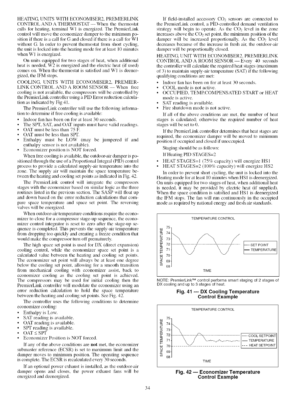
HEATING.UNITSWITHECONOMISER2,PREMIERLINK
CONTROLANDA THERMOSTAT-- Whenthethermostat
c_dlsforheating,terminalWI isenergized.ThePremierLink
controlwillmovetheeconomizerdampertotheminimumpo-
sitionif thereisacallforGandclosedif thereisacallforWI
withoutG Inordertopreventthermostatfromshortcycling,
theunitislockedintotheheatingmodeforatleast10minutes
whenWI isenergized.
Onunitsequippedfortwostagesofheat,whenadditional
heatisneeded,W2isenergizedandtheelectricheat(if used)
comeson.WhenthethermostatissatisfiedandWI isdeener-
gized,theIFMstops.
COOLING. UNITS WITH ECONOMISER2, PREMIER-
LINK CONTROL AND A ROOM SENSOR -- When free
cooling is not available, the compressors will be controlled by
the PremierLink controller using a PID Error reduction c_flcula-
tion as indicated by Fig 41.
The PremierLink controller will use the following informa-
tion to determine if free cooling is available:
• Indoor fan has been on for at least 30 seconds.
• The SPT. SAT. and OAT inputs must have valid readings.
• OAT must be less than 75 F.
• OAT must be less than SPT.
• Enthalpy must be LOW (may be jumpered if and
enthalpy sensor is not available).
• Economizer position is NOT forced.
When free cooling is available, the outdoor-air damper is po-
sitioned through the use of a Proportional Integral (PlD) control
process to provide a calculated supply-air temperature into the
zone. The supply air will maintain the space temperature be-
tween the heating and cooling set points as indicated in Fig. 42.
The PremierLink control will integrate the compressol.s
stages with the economizer based on simiku logic as the three
routines listed in the previous section. The SASP will float up
and down based on the error reduction calculations that com-
ptue space temperature and space set point. The reversing
valves will be energized.
When outdoor-air temperature conditions require the econo-
mizer to close for a compressor stage-up sequence, the econo-
mizer control integrator is reset to zero after the stage-up se-
quence is completed. This prevents the supply-air temperature
from &opping too quickly and creating a freeze condition that
would make the compressor turn off prematurely.
The high space set point is used for DX (direct expansion)
cooling control, while the economizer space set point is a
c_dculated value between the heating and cooling set points.
The economizer set point will always be at least one degree
below the cooling set point, allowing for a smooth transition
from mechanical cooling with economizer assist, back to
economizer cooling as the cooling set point is achieved.
The compressors may be used for initkfl cooling then the
PremierLink controller will modulate file economizer using an
enor reduction calculation to hold the space temperature
between the heating and cooling set points. See Fig. 42.
The controller uses the following conditions to determine
economizer cooling:
• Enthalpyis Low.
• SAT reading is available.
• OAT reading is available.
• SPT reading is available.
• OAT < SPT
• Economizer Position is NOT forced.
If any of the above conditions are not met, the economizer
submaster reference (ECSR) is set to maximum limit and the
dmnper moves to minimum position. The operating sequence
is complete. The ECSR is recalculated every 30 seconds.
If an optional power exhaust is inst_dled, as the outdoor-air
dmnper opens and closes, the power exhaust fans will be
energized and deenergized.
If field-installed accessory CO2 sensors tue connected to
the PremierLink control, a PID-controlled demand ventilation
strategy will begin to operate. As the CO2 level in file zone
increases above the CO2 set point, the minimum position of the
damper will be increased proportionally. As the CO2 level
decreases because of the increase in fresh all: the outdoor-air
damper will be proportionally closed.
HEATING. UNIT WITH ECONOMISER2, PREMIERLINK
CONTROL AND A ROOM SENSOR -- Every 40 seconds
the controller will calculate the required heat stages (maximum
of 3) to maintain supply-air temperature (SAT) if the following
qu_difying conditions are met:
• Indoor fan has been on for at least 30 seconds.
• COOL mode is not active.
• OCCUPIED, TEMRCOMPENSATED START or HEAT
mode is active.
• SAT reading is available.
• Fire shutdown mode is not active.
If all of the above conditions me met, the number of heat
stages is c_dculated; otherwise the required number of heat
stages will be set to 0.
If file PremierLink controller determines that heat stages are
required, the economizer dmnper will be moved to minimum
position if occupied and closed if unoccupied.
Staging should be as follows:
If Heating PID STAGES=2
• HEAT STAGES=I (75% capacity) will energize HSI
• HEAT STAGES=2 (100% capacity) will energize HS2
In order to prevent short cycling, the unit is locked into the
Heating mode forat least 10 minutes when HSI is deenergized.
On units equipped for two stages of heat, when additional heat
is needed, it may be provided by electric heat (if supplied).
When the space condition is satisfied and HSI is deenergized
the IFM stops. The fan will mn continuously in the occupied
mode as required by national energy and fresh air standards.
75,
W
744
_: 734
££
nm 724
714
I-
w704
o
694
co 68 J
TEMPERATURE CONTROL
TIME
...... SET POINT
I TEMPERATURE
NOTE: PremierLinkTM control performs smart staging of 2 stages of
DX cooling and up to 3 stages of heat.
Fig. 41 -- DX Cooling Temperature
Control Example
W
OC
W
w
W
o
69
TEMPERATURE CONTROL
75
74 1_.__
73
72 ......... _ .................................... ------COOL SETPO[NT
711 \ /j __ -- TEMPERATURE
704 ........ _v_ .......................... --- HEAT SETPOINT
J
69
68
TIME
Fig. 42 -- Economizer Temperature
Control Example
34
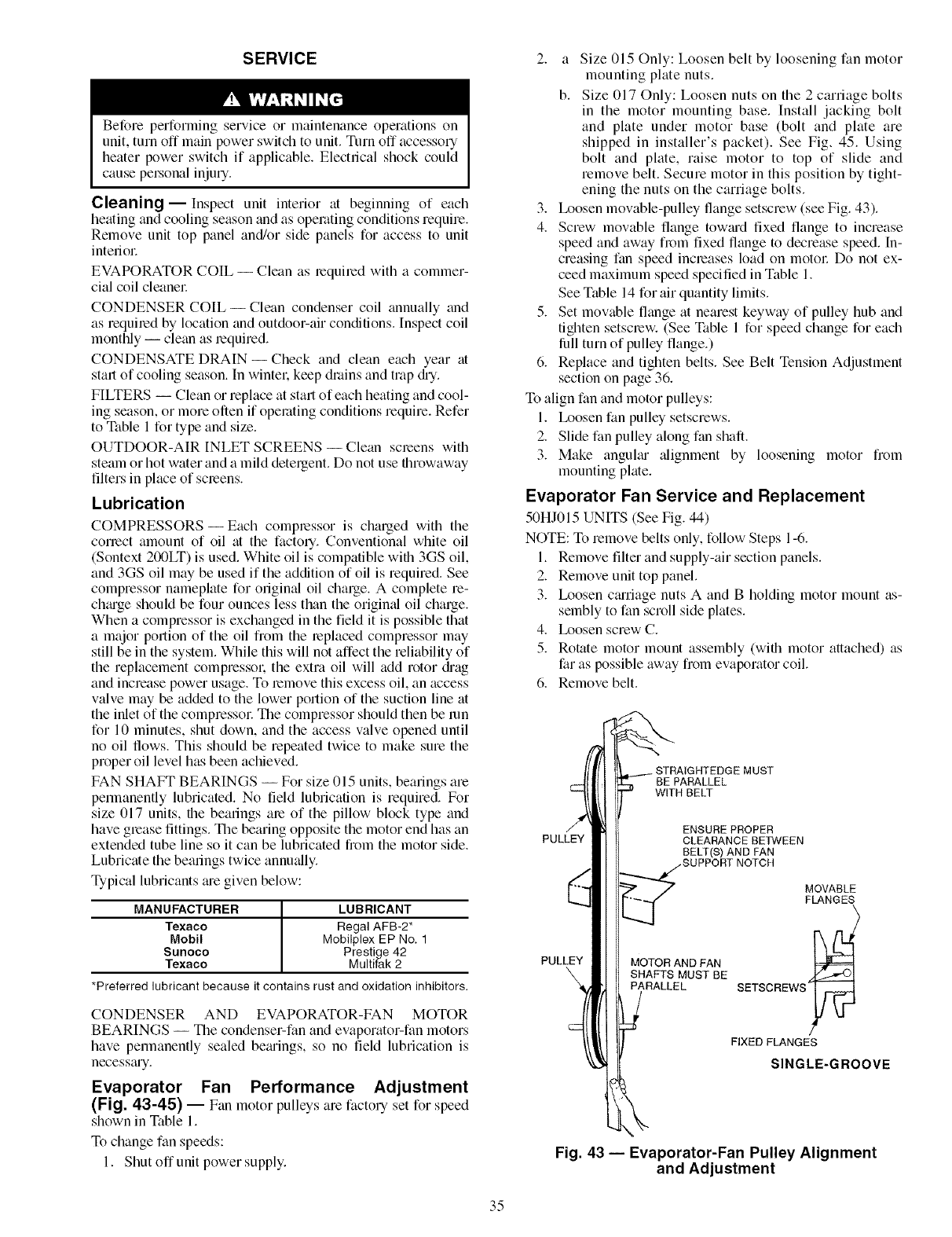
SERVICE
Before performing service or maintenance operations on
unit, turn off main power switch to unit. Tnm off accessory
heater power switch if applicable. Electrical shock could
cause pelNonal injury.
Cleaning- Inspect unit interior at beginning of each
heating and cooling season and as operating conditions require.
Remove unit top panel and/or side panels for access to unit
interiol:
EVAPORATOR COIL -- Clean as required with a commer-
cial coil cleanel:
CONDENSER COIL--Clean condenser coil annually and
as required by location and outdoor-air conditions. Inspect coil
monthly -- clean as require&
CONDENSATE DRAIN- Check and clean each year at
start of cooling season. In wintel: keep drains and trap &T.
FILTERS -- Clean or replace at start of each heating and cool-
ing season, or more often if operating conditions require. Refer
to Table 1 for type and size.
OUTDOOR-AIR INLET SCREENS -- Clean screens with
steam or hot water and a mild detergent. Do not use throwaway
filters in place of screens.
Lubrication
COMPRESSORS- Each compressor is charged with the
correct amount of oil at the factory. Conventional white oil
(Sontext 200LT) is used. White oil is compatible with 3GS oil,
and 3GS oil may be used if the addition of oil is required. See
compressor nameplate for origimd oil charge. A complete re-
ch_uge should be four ounces less than the origimd oil charge.
When a compressor is exchanged in the field it is possible that
a major portion of the oil from the replaced compressor may
still be in the system. While this will not affect the reliability of
the replacement compressol: the extra oil will add rotor diag
and increase power usage. To remove this excess oil, an access
valve may be added to the lower portion of the suction line at
the inlet of the compressol: The compressor should then be mn
for 10 minutes, shut down, and the access valve opened until
no oil flows. This should be repeated twice to make sure the
proper oil level has been achieved.
FAN SHAFT BEARINGS -- For size 015 units, bearings are
permanently lubricated. No field lubrication is required. For
size 017 units, the bearings are of the pillow block type and
have grease fittings. The bearing opposite the motor end has an
extended tube line so it can be lubricated from the motor side.
Lubricate the bearings twice annu_dly.
Typical lubricants _ue given below:
MANUFACTURER LUBRICANT
Texaco Regal AFB-2*
Mobil Mobilplex EP No. 1
Sunoco Prestige 42
Texaco Multifak 2
*Preferred lubricant because it contains rust and oxidation inhibitors.
CONDENSER AND EVAPORATOR-FAN MOTOR
BEARINGS -- The condenser-fan and evaporator-fan motors
have permanently sealed beguings, so no field lubrication is
necessguy.
Evaporator Fan Performance Adjustment
(Fig. 43-45) -- Fan motor pulleys are factory set for speed
shown in Table 1.
To change fan speeds:
1. Shut off unit power supply.
2. a Size 015 Only: Loosen belt by loosening fan motor
mounting plate nuts.
b. Size 017 Only: Loosen nuts on the 2 carriage bolts
in the motor mounting base. Install jacking bolt
and plate under motor base (bolt and plate are
shipped in installer's packet). See Fig, 45. Using
bolt and plate, raise motor to top of slide and
remove belt. Secure motor in this position by tight-
ening the nuts on the carriage bolts.
3. Ix_osen movable-pulley flange setscrew (see Fig. 43).
4. Screw movable flange tow_ud fixed flange to increase
speed and away from fixed flange to decrease speed. In-
creasing fan speed increases load on motol: Do not ex-
ceed mtcximum speed specified in Table 1.
See Table 14 for air quantity limits.
5. Set movable flange at nearest keyway of pulley hub and
tighten setscrew. (See Table 1 for speed change for each
lhll turn of pulley flange.)
6. Replace and tighten belts. See Belt Tension Adjustment
section on page 36.
To align fan and motor pulleys:
1. Ix_osen fan pulley setscrews.
2. Slide fan pulley along fan shaft.
3. Make anguku" alignment by loosening motor from
mounting plate.
Evaporator Fan Service and Replacement
50HJ015 UNITS (See Fig. 44)
NOTE: To remove belts only, follow Steps 1-6.
1. Remove filter and supply-air section panels.
2. Remove unit top panel.
3. Ix_osen cguriage nuts A and B holding motor mount as-
sembly to fan scroll side plates.
4. Ix_osen screw C.
5. Rotate motor mount assembly (with motor attached) as
far as possible away from evaporator coil.
6. Remove belt.
PULLEY
PULLEY
BE PARALLEL
WITH BELT
ENSURE PROPER
CLEARANCE BETWEEN
8ELT(_ AND FAN
MOTOR AND FAN
SHAFTS MUST BE
PARALLEL
MOVABLE
FLANGES
SETSCREWS
FIXED FLANGES
SINGLE-GROOVE
Fig. 43 -- Evaporator-Fan Pulley Alignment
and Adjustment
35
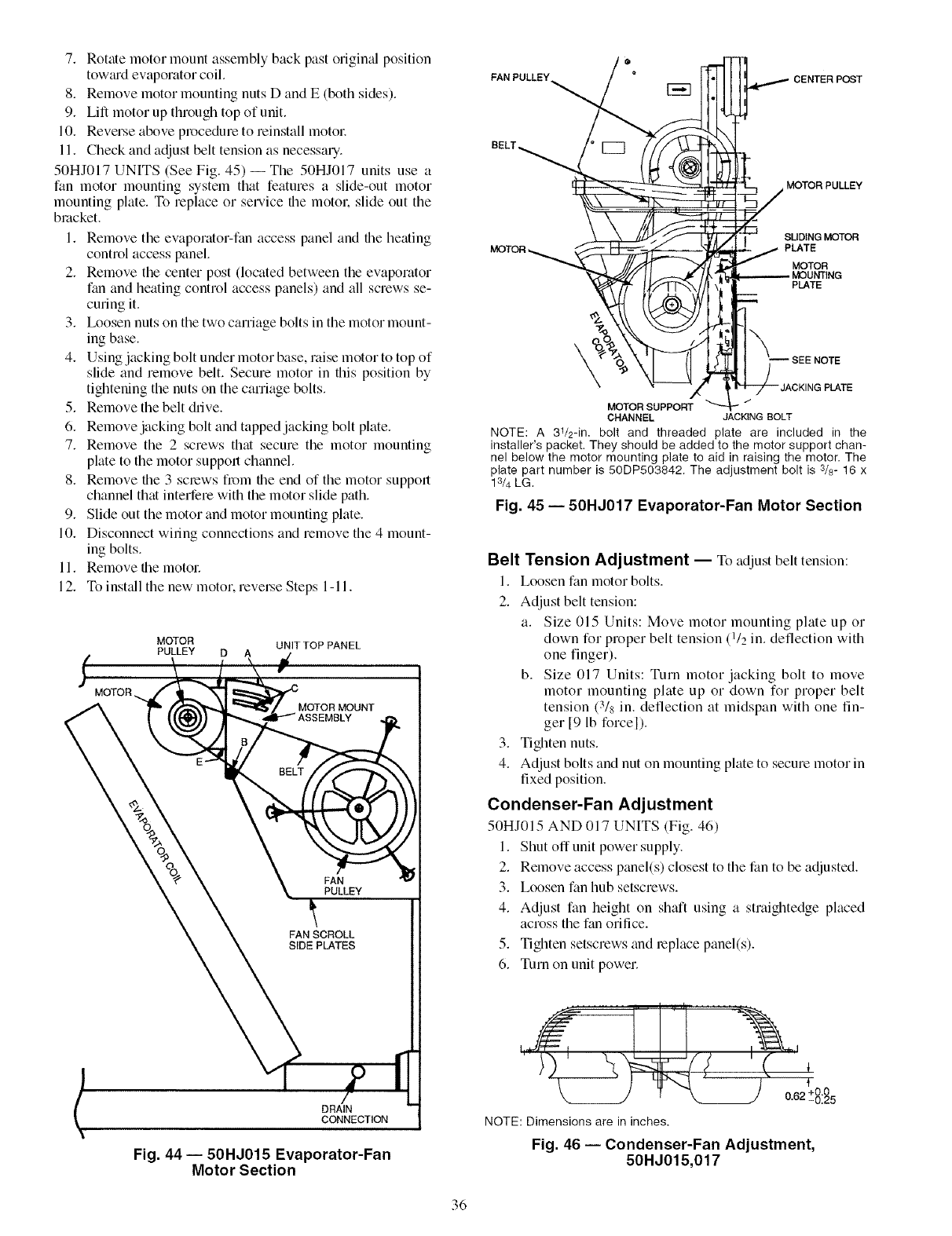
7. Rotate motor mount assembly back past original position
tow_ud evaporator coil.
8. Remove motor mounting nuts D and E (both sides).
9. Lift motor up through top of unit.
10. Reverse above procedure to reinstall motol:
11. Check and adjust belt tension as necessary.
50HJ017 UNITS (See Fig. 45)--The 50HJ017 units use a
fan motor mounting system that features a slide-out motor
mounting plate. To replace or service file motor, slide out the
bracket.
1. Remove the evaporator-fan access panel and file heating
control access panel.
2. Remove the center post (located between the evaporator
fan and heating control access panels) and all screws se-
curing it.
3. Ix_osen nuts on the two carriage bolts in the motor mount-
ing base.
4. Using jacking bolt under motor base, raise motor to top of
slide and remove belt. Secure motor in this position by
tightening the nuts on the carriage bolts.
5. Remove the belt drive.
6. Remove jacking bolt and tapped jacking bolt plate.
7. Remove the 2 screws that secure the motor mounting
plate to the motor support channel.
8. Remove the 3 screws from file end of the motor support
channel that interfere with the motor slide path.
9. Slide out the motor and motor mounting plate.
10. Disconnect wiring connections and remove the 4 mount-
ing bolts.
11. Remove file motol:
12. To inst_dl the new motor, reveLse Steps 1-11.
MOTOR _.
MOTOR UNIT TOP PANEL
PULLEY D A
FAN
_, PULLEY
FAN SCROLL
SIDE PLATES
DRAIN
CONNECTION
Fig. 44 -- 50HJ015 Evaporator-Fan
Motor Section
FAN PULLEY_
CENTER POST
BELT
MOTOR PULLEY
SUDING MOTOR
MOTOR _PLATE
MOTOR
PLATE
\
MOTORSUPPORT
CHANNEL JACKINGBOLT
NOTE: A 31/2-in. bolt and threaded plate are included in the
installer's packet. They should be added to the motor support chan-
nel below the motor mounting plate to aid in raising the motor. The
plate part number is 50DP503842. The adjustment bolt is 3/8- 16 x
13/4 LG.
Fig. 45 -- 50HJ017 Evaporator-Fan Motor Section
Belt Tension Adjustment -- To adjust belt tension:
1. Loosen fan motor bolts.
2. Adjust belt tension:
a. Size 015 Units: Move motor mounting plate up or
down for proper belt tension (1/2 in. deflection with
one finger).
b. Size 017 Units: Turn motor jacking bolt to move
motor mounting plate up or down for proper belt
tension (3/8 in. deflection at midspan with one fin-
ger [9 lb forcel).
3. Tighten nuts.
4. Adjust bolts and nut on mounting plate to secure motor in
fixed position.
Condenser-Fan Adjustment
50HJ015 AND 017 UNITS (Fig. 46)
1. Shut off unit power supply.
2. Remove access panel(s) closest to the fan to be adjusted.
3. Loosen fan hub setscrews.
4. Adjust fan height on shaft using a straightedge placed
across the fan orifice.
5. Tighten setscrews and replace panel(s).
6. Turn on unit power.
_ 0"62 +-8:_5
NOTE: Dimensions are in inches.
Fig. 46 -- Condenser-Fan Adjustment,
50HJ015,017
36
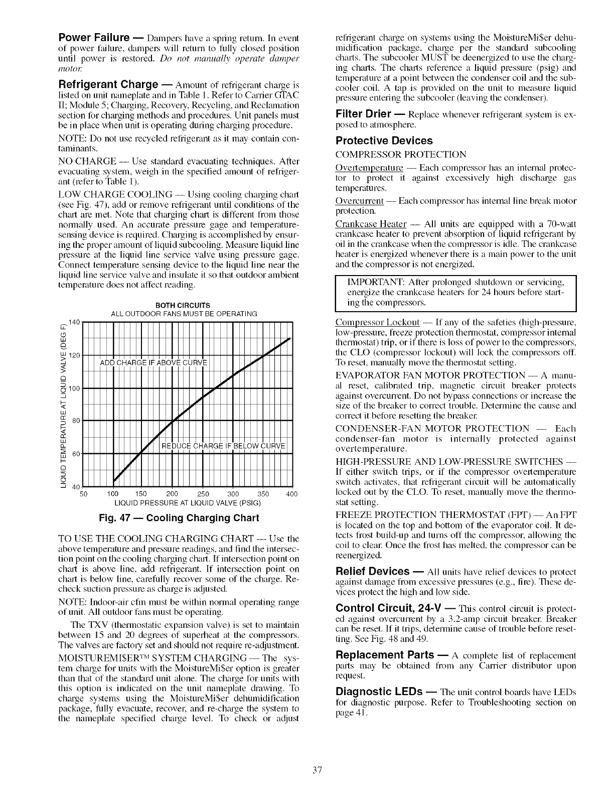
Power Failure -- Dampers have a spring return. In event
of power failure, &tmpo.s will return to fully closed position
until power is restored. Do not manually operate damper
gO_()E
Refrigerant Charge -- Amount of refligelant chalge is
listed on unit nameplate and in Table 1. Refer to Cmrier GI'AC
II; Module 5; Charging, Recovery, Recycling, and Reclmnation
section for chmging methods and procedures. Unit panels must
be in place when unit is operating during charging procedure.
NOTE: Do not use recycled refligerant as it may contain con-
taminants.
NO CHARGE -- Use standard evacuating techniques. After
evacuating system, weigh in the specified alnount of refriger-
ant (refer to Table 1).
LOW CHARGE COOLING -- Using cooling charging chart
(see Fig. 47), add or remove refrigerant until conditions of the
chmt are met. Note that chmging chmt is different from those
norm;ally used. An accurate pressure gage and temperature-
sensing device is required. Charging is accomplished by ensur-
ing the proper amount of liquid subcooling. Measure liquid line
pressure at the liquid line service valve using pressure gage.
Connect temperature sensing device to the liquid line nero the
liquid line service valve and insulate it so that outdoor ambient
temperature does not affect reading.
BOTH CIRCUITS
ALL OUTDOOR FANS MUST BE OPERATING
50 100 150 200 250 300 350 400
LIQUID PRESSURE AT LIQUID VALVE (PSIG)
Fig. 47 -- Cooling Charging Chart
TO USE THE COOLING CHARGING CHART -- Use the
above temperature and pressure readings, and find the intersec-
tion point on the cooling charging chart. If intersection point on
chin1 is above line, add refrigerant. If intersection point on
chmt is below line, carefully recover some of the charge. Re-
check suction pressure as charge is adjusted.
NOTE: Indoor-air cfm must be within normal operating range
of unit. All outdoor fans must be operating.
The TXV (thermostatic expansion valve) is set to maintain
between 15 and 20 degrees of superheat at the compressors.
The valves are factory set and should not require re-adjustment.
MOISTUREMISER TM SYSTEM CHARGING -- The sys-
tem charge for units with the MoistureMiSer option is greater
than that of the stan&_rd unit _done. The charge for units with
this option is indicated on the unit nameplate &awing. To
chmge systems using the MoistureMiSer dehumidification
package, fully evacuate, recover, and re-chmge the system to
the nameplate specified charge level. To check or adjust
refrigerant chm'ge on systems using the MoistureMiSer dehu-
midification package, charge per the stan&ud subcooling
charts. The subcooler MUST be deenergized to use the charg-
ing charts. The charts reference a liquid pressure (psig) and
temperature at a point between the condenser coil and the sub-
cooler coil. A tap is provided on the unit to measure liquid
pressure entering the subcooler (leaving the condenser).
Filter Drier -- Replace whenever refrigerant system is ex-
posed to atmosphere.
Protective Devices
COMPRESSOR PROTECTION
Overtemperature -- Each compressor has an intern_fl protec-
tor to protect it against excessively high discharge gas
temperatures.
Overcurrent -- Each compressor has internal line break motor
protection.
Crankcase Heater -- All units are equipped with a 70-watt
crankcase heater to prevent absorption of liquid refrigerant by
oil in the crankcase when the compressor is idle. The crankcase
heater is energized whenever there is a main power to the unit
and the compressor is not energized.
IIMPORTANT: After prolonged shutdown or servicing, I
energize the crankcase heaters for 24 houLs before stmt- I
ing the compressors.
Compressor Lockout -- If any of the safeties (high-pressure,
low-pressure, freeze protection thermostat, compressor internal
thermostat) trip, or if there is loss of power to the compressors,
the CLO (compressor lockout) will lock the compressors off.
To reset, manu_dly move the thermostat setting.
EVAPORATOR FAN MOTOR PROTECTION -- A manu-
_fl reset, calibrated trip, magnetic circuit breaker protects
against overcurrent. Do not bypass connections or increase the
size of the breaker to correct trouble. Determine the cause and
correct it before resetting the breakel:
CONDENSER-FAN MOTOR PROTECTION -- Each
condenser-fan motor is internally protected against
overtemperature.
HIGH-PRESSURE AND LOW-PRESSURE SWITCHES --
If either switch trips, or if the compressor overtemperature
switch activates, that refrigerant circuit will be automatically
locked out by the CLO. To reset, manually move the thermo-
stat setting.
FREEZE PROTECTION THERMOSTAT (FPT) -- An FPT
is located on the top and bottom of the evaporator coil. It de-
tects frost build-up and turns off the compressor, allowing the
coil to clem: Once the frost has melted, the compressor can be
reenergized.
Relief Devices -- All units have relief devices to protect
against &_mage from excessive pressures (e.g., fire). These de-
vices protect the high and low side.
Control Circuit, 24-7 -- This control circuit is protect-
ed against overcunent by a 3.2-amp circuit breakel: Breaker
can be reset. If it trips, determine cause of trouble before reset-
ting. See Fig. 48 and 49.
Replacement Parts -- A complete list of replacement
parts may be obtained from any Carrier distributor upon
request.
Diagnostic LEDs -- The unit control bo_uds have LEDs
for diagnostic purpose. Refer to Troubleshooting section on
page 41.
37

Optional Hinged Access Doors --When the optional
service package is ordered or the if the hinged access doors
option is ordered, the unit will be provided with external and
internal hinged access dool_ to facilitate service.
Four external hinged access doors are provided. All extern_d
doors me provided with 2 lalge 1/4 turn latches with folding
bail-type handles. (Compressor access doors have one latch.) A
single door is provided for filter and drive access. One door is
provided for control box access. The control box access door is
interlocked with the non-fused disconnect which must be in the
OFF position to open the dool: Two doors are provided for ac-
cess to the compressor comp_utment.
Two internal access doors are provided inside the tilter/
drive access dool: The filter access door (on the left) is secured
by 2 small 1/4 turn latches with folding bail-type handles. This
door must be opened prior to opening the drive access dool:
The (hive access door is shipped with 2 sheet metal screws
holding the door closed. Upon initial opening of the dooL these
screws may be removed and discarded. The door is then held
shut by the tilter access door. which closes over it.
38
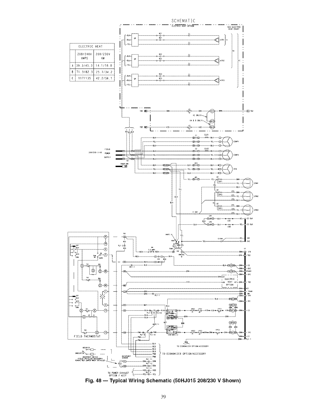
A
B
C
ELECTRIC HEAT
2081240V 200/230V
AHPS KW
393/453 1411188
7131823 2571342
117/135 42.2/561
_IELD
2eB1_30-3 6e _OWER
SUPPLY
SCHEMATIC
[L[CT_IC_EAT OPTION S_E_L_¢_IC
YE _
H_3
YE
LS
c_ CLO_
I
I
I
I
I
I
I
I
J _'"-£_4 )....
I
I
IL°?_LJ _ct
_rc
ire
Fig. 48 -- Typical Wiring Schematic (50HJ015 208/230 V Shown)
39

AHA
C
CAP
CB
CO
OH
CLO
COMP --
OR
DM
DU
EQUIP --
FL
FPT
FU
GND
HC
HPS
HTR
IAQ
IFC
IFM
IFR
L
LOR
LPS
LS
NEC
OAT
OCCUP --
OFC
OFM
PL
PRI
QT
RAT
SW
TB
TC
TH
TRAN
o
[_ ELECTRIC HEAl OPIIOH
L_
COMPONENT ARRANGEMENT
(A)
I [_ [_]ZL[CTRIC HZAT OPTION lI _ [_[_ZLECTRIC HZAT OP_ IO_ ]i
I I
(B) (C)
0_°:°I ='%=,
--\ :[]:
LEGEND
Adjustable, Heat Anticipator
Contactor, Compressor
Capacitor
Circuit Breaker
Cooing Compensator
Crankcase Heater
Compressor Lockout
Compressor Motor
Control Relay
Damper Motor
Dummy Terminal
Equipment
Filament
Freeze Protection Thermostat
Fuse
Ground
Heater Contactor
High-Pressure Switch
Heater
Indoor Air Quality Sensor
Indoor Fan Contactor
Indoor Fan Motor
Indoor Fan Relay
Light
Lockout Relay
Low-Pressure Switch
Limit Switch
National Electrical Code
Outdoor Air Temperature Sensor
Occupancy Sensor
Outdoor Fan Contactor
Outdoor Fan Motor
Plug Assembly
Prknary
Quadruple Terminal
Return Air Temperature Sensor
Switch
Terminal Block
Thernlostat Cooling
Thermostat Heating
Transformer
Terminal (Marked)
Terminal (Unmarked)
'I ,IiI_
=IBII
PL_
COnTrOL
BOX
RL_-8
pLI.lO _rlg£O $_tIC{
Y_L
-- ORN
s[l$11 (ll (}I) It_s
LI_EI--
_'Y2=,E_°,_ o'_,
,,,-,_,._,=_°9:2q-×- i ,,_1_'; 0
l_es[wso_
[_ Terminal Block
• Splice
-- Factory Wiring
Field Control Wiring
.... Accessory or Optional Wiring
To indicate common potential only;
not to represent wiring.
Economizer Motor
Remote POT Field Accessory
OAT Sensor
Disch Air Sensor
RAT Accessory Sensor
Low Ambient Lockout Switch
NOTES:
1. Compressor and/or fan motor(s) thermally protected three phase
motors protected against primary single phasing conditions.
2. If any of the original wire furnished must be replaced, it must be
replaced with Type 90 ° C or its equivalent.
3. Jumpers are omitted when unit is equipped with economizer.
4. IFCB must trip amps is equal to or less than 140% FLA.
5. On TRAN1 use BLK lead for 460-v power supply and ORN lead for
575w power supply.
6. The CLO locks out the compressor to prevent short cycling on corm
pressor overload and safety devices; before replacing CLO check
these devices.
7. Number(s) indicates the line location of used contacts. A bracket
over (2) numbers signifies a single pole, double throw contact. An
underlined number signifies a normally closed contact. Plain (no
line) number signifies a normally open contact.
8. 620 Ohm, 1 watt, 5% resistor should be removed only when using
differential enthalpy or dry bulb.
9. If a separate field-supplied 24 v transformer is used for the IAQ
sensor power supply, it cannot have the secondary of the trans-
former grounded.
10. OAT sensor is shipped inside unit and must be relocated in the field
for proper operation.
11. For field installed remote minimum position POT. remove black wire
jumper between P and P1 and set control minimum posgion POT to
the minimum position.
Fig. 49 -- Typical Component Arrangement (50HJ015 Unit Shown)
40
TROUBLESHOOTING
Unit Troubleshooting -- Refer to Tables 19 and 20 for
troubleshooting details.
EconoMiSerlV Troubleshooting-- See Table 21
for EconoMi$erIV logic.
A limctional view of file EconoMiSerIV is shown in Fig. 50.
Typic;d settings, sensor ranges, and jumper positions ;ue also
shown. An EconoMiSerIV simuhttor program is available from
Cartier to help with EconoMiSerlV training and troubleshooting.
ECONOMISERIV PREPARATION -- This procedure is
used to prepare the EconoMiSerIV for troubleshooting. No
troubleshooting or testing is done by performing the following
procedure.
NOTE: This procedure requires a 9-v battery. 1.2 kilo-ohln
resistol: and a 5.6 kilo-ohm resistor which are not supplied
with the EconoMiSerlV.
IMPORTANT: Be sure to record the positions of all poten-tiometers before starting troubleshooting.
1. Disconnect power at TR and TRI. All LEDs should be
off. Exhaust fan contacts should be open.
2. Disconnect device at P and PI.
3. Jumper P to PI.
4. Disconnect wires at T and TI. Place 5.6 kilo-ohm resistor
across T and TI.
5. Jumper TR to 1.
6. Jumper TR to N.
7. If connected, remove sensor from terminals So and +.
Connect 1.2 kilo-ohm 4074EJM checkout resistor across
terminals So and +.
8. Put 620-ohm resistor across terminals SR and +.
9. Set minimum position, DCV set point, and exhaust
potentiometers fully CCW (counterclockwise).
10. Set DCV maximum position potentiometer lhlly CW
Iclockwise).
11. Set enthalpy potentiometer to D.
12. Apply power (24 vac) to termimds TR and TRI.
DIFFERENTIAL ENTHALPY-- To check differential
enthalpy:
1. Make sure EconoMiSerIV preparation procedure has
been performed.
2. Place 620-ohm resistor across So and +.
3. Place 1.2 kilo-ohm resistor across SR and +. The Free
Cool LED should be lit.
4. Remove 620-ohm resistor across So and +. The Free
Cool LED should turn off.
5. Return EconoMiSerIV settings and wiring to normal
after completing troubleshooting.
SINGLE ENTHALPY -- To check single enth_dpy:
1. Make sure EconoMiSerIV preparation procedme has
been performed.
2. Set the enthalpy potentiometer to A (fully CCW). The
Free Cool LED should be lit.
3. Set the enthalpy potentiometer to D (fully CW). The Free
Cool LED should turn off.
4. Return EconoMiSerIV settings and wiring to normal
after completing troubleshooting.
DCV (Demand Controlled Ventilation) AND POWER
EXHAUST -- To check DCV and Power Exhaust:
1. Make sure EconoMiSerlV preparation procedure has
been performed.
2. Ensure terminals AQ and AQI are open. The LED for
both DCV and Exhaust should be off. The actuator
should be fully closed.
3. Connect a 9-v battery to AQ (positive node) and AQI
(negative node). The LED for both DCV and Exhaust
should turn on. The actuator should drive to between 90
and 95% open.
4. Turn the Exhaust potentiometer CW until the Exhaust
LED turns off. The LED should turn off when the
potentiometer is approximately 90%. The actuator should
lemain in position.
5. Turn the DCV set point potentiometer CW until the DCV
LED turns off. The DCV LED should turn off when the
potentiometer is approximately 9-v. The actuator should
(hive fully closed.
6. Turn the DCV and Exhaust potentiometers CCW until
the Exhaust LED turns on. The exhaust contacts will
close 30 to 120 seconds after the Exhaust LED turns on.
7. Return EconoMiSerlV settings and wiring to norlnal
after completing troubleshooting.
DCV MINIMUM AND MAXIMUM POSITION -- To check
the DCV minimum and maximum position:
1. Make sure EconoMiSerIV preparation procedure has
been performed.
2. Connect a 9-v battery to AQ (positive node) and AQI
(negative node). The DCV LED should turn on. The
actuator should drive to between 90 and 95% open.
3. Turn the DCV Maximum Position potentiometer to mid-
point. The actuator should drive to between 20 and 80%
open.
4. Turn the DCV Maximum Position potentiometer to fully
CCW. The actuator should drive fully closed.
5. Turn the Minimum Position potentiometer to midpoint.
The actuator should drive to between 20 and 80% open.
6. Turn the Minimum Position Potentiometer fully CW. The
actuator should drive fully open.
7. Remove the jumper from TR and N. The actuator should
chive fully closed.
8. Return EconoMi$erIV settings and wiring to normal
after completing troubleshooting.
SUPPLY-AIR INPUT -- To check supply-air input:
1. Make sure EconoMiSerlV preparation procedure has
been performed.
2. Set the Enthalpy potentiometer to A. The Free Cool LED
turns on. The actuator should drive to between 20 and
80% open.
3. Remove the 5.6 kilo-ohm resistor and jumper T to TI.
The actuator should drive fully open.
4. Remove the jumper across T and TI. The actuator should
(hive fully closed.
5. Return EconoMiSerIV settings and wiring to normal
after completing troubleshooting.
ECONOMISER IV TROUBLESHOOTING COMPLE-
TION -- This procedure is used to return the EconoMiSerlV
to operation. No troubleshooting or testing is done by perform-
ing the following procedure.
1. Disconnect power at TR and TRI.
2. Set enthalpy potentiometer to previous setting.
3. Set DCV maximum position potentiometer to previous
setting.
4. Set minimum position, DCV set point, and exhaust
potentiometel_ to previous settings.
5. Remove 620-ohm resistor from terminals SR and +.
6. Remove 1.2 kilo-ohln checkout resistor from termimfls So
and +. If used, reconnect sensor from tennin_ds So and +.
7. Remove jumper from TR to N.
8. Remove jumper from TR to 1.
9. Remove 5.6 kilo-ohln resistor from T and TI. Reconnect
wires at T and TI.
10. Remove jumper from P to PI. Reconnect device at P and
PI.
11. Apply power (24 vac) to terminals TR and TRI.
41

Table 19 -- MoistureMi$er TM Dehumidification Subcooler Service Analysis
PROBLEM
Subcooler Will Not Energize
CAUSE
No power to subcooler
control transformer.
No power from subcooler control transformer to
liquid line three-way valve.
Liquid line three-way valve
will not operate.
Subcooler Will Not Deenergize Liquid Line three-way valve
will not close.
Low System Capacity Low refrigerant charge or 1. Check charge amount. See system charging
frosted coil. section.
2, Evaporator coil frosted; check and replace
subcooler control low-pressure switch if necessary.
REMEDY
Check power source. Ensure all wire connections
are tight.
1, Fuse open; check fuse, Ensure continuity of wiring.
2, Subcooler control low-pressure switch open,
Cycle unit off and allow low-pressure switch
to reset, Replace switch if it will not close.
3. Transformer bad; check transformer.
1, Solenoid coil defective; replace.
2, Solenoid valve stuck closed; replace.
Valve is stuck open; replace.
42
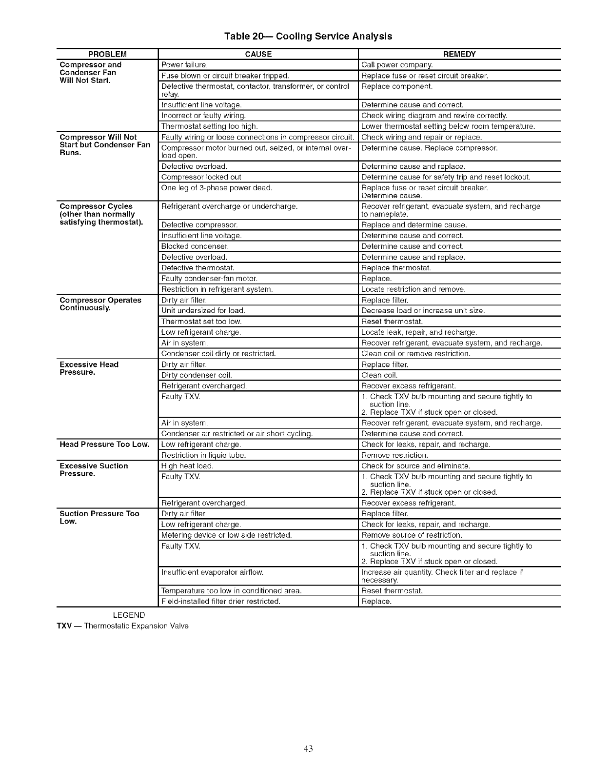
Table 20-- Cooling Service Analysis
PROBLEM CAUSE REMEDY
Compressor and Power failure. Call power company.
Condenser Fan Fuse blown or circuit breaker tripped. Replace fuse or reset circuit breaker.
Will Not Start. Defective thermostat, contactor, transformer, or control Replace component.
relay.
Insufficient line voltage. Determine cause and correct.
Incorrect or faulty wiring. Check wiring diagram and rewire correctly.
Thermostat setting too high. Lower thermostat setting below room temperature.
Compressor Will Not Faulty wiring or loose connections in compressor circuit. Check wiring and repair or replace.
Start but Condenser Fan Compressor motor burned out, seized, or internal over- Determine cause. Replace compressor.
Runs. load open.
Defective overload. Determine cause and replace.
Compressor locked out Determine cause for safety trip and reset lockout.
One leg of 3-phase power dead. Replace fuse or reset circuit breaker.
Determine cause.
Compressor Cycles Refrigerant overcharge or undercharge. Recover refrigerant, evacuate system, and recharge
(other than normally to nameplate.
satisfying thermostat). Defective compressor. Replace and determine cause.
Insufficient line voltage. Determine cause and correct.
Blocked condenser. Determine cause and correct.
Defective overload. Determine cause and replace.
Defective thermostat. Replace thermostat.
Faulty condenser-fan motor. Replace.
Restriction in refrigerant system. Locate restriction and remove.
Compressor Operates Dirty air filter. Replace filter.
Continuously. Unit undersized for load. Decrease load or increase unit size.
Thermostat set too low. Reset thermostat.
Low refrigerant charge. Locate leak, repair, and recharge.
Air in system. Recover refrigerant, evacuate system, and recharge.
Condenser coil dirty or restricted. Clean coil or remove restriction.
Excessive Head Dirty air filter. Replace filter.
Pressure. Dirty condenser coil. Clean coil.
Refrigerant overcharged. Recover excess refrigerant.
Faulty TXV. 1. Check TXV bulb mounting and secure tightly to
suction line.
2. Replace TXV if stuck open or closed.
Air in system. Recover refrigerant, evacuate system, and recharge.
Condenser air restricted or air short-cycling. Determine cause and correct.
Head Pressure Too Low. Low refrigerant charge. Check for leaks, repair, and recharge.
Restriction in liquid tube. Remove restriction.
Excessive Suction High heat load. Check for source and eliminate.
Pressure. Faulty TXV. 1. Check TXV bulb mounting and secure tightly to
suction line.
2. Replace TXV if stuck open or closed.
Refrigerant overcharged. Recover excess refrigerant.
Suction Pressure Too Dirty air filter. Replace filter.
Low. Low refrigerant charge. Check for leaks, repair, and recharge.
Metering device or low side restricted. Remove source of restriction.
Faulty TXV. 1. Check TXV bulb mounting and secure tightly to
suction line.
2. Replace TXV if stuck open or closed.
Insufficient evaporator airflow. Increase air quantity. Check filter and replace if
necessary.
Temperature too low in conditioned area. Reset thermostat.
Field-installed filter drier restricted. Replace.
LEGEND
TXV -- Thermostatic Expansion Valve
43
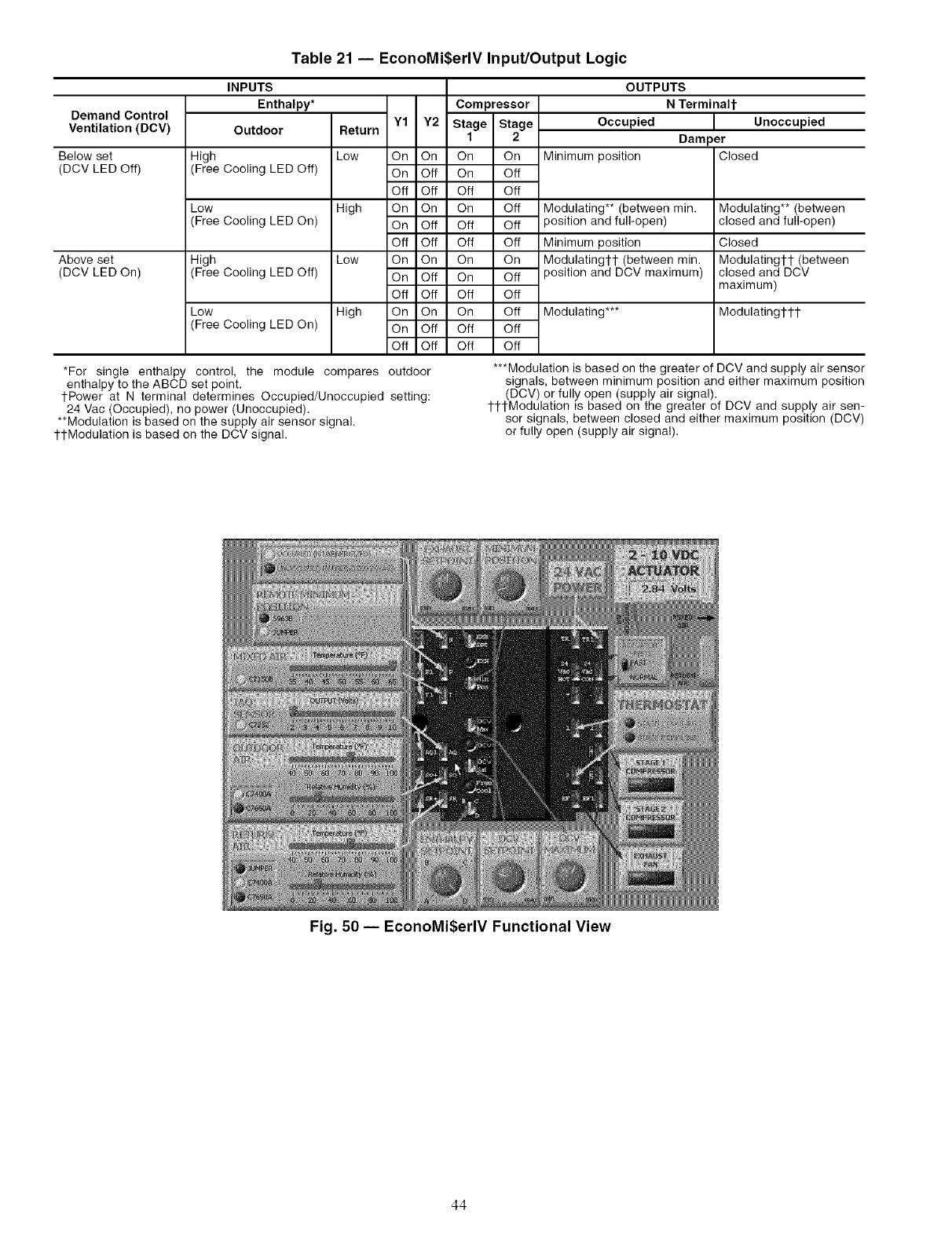
Table 21 -- EconoMi$erlV Input/Output Logic
Demand Control
Ventilation (DCV)
Below set
(DCV LED Off)
Above set
(DCV LED On)
INPUTS
Enthalpy* Compressor
Outdoor Return Y1 Y2 Stage Stage
1 2
High Low On On On On
(Free Cooling LED Off) On Off On Off
Off Off Off Off
Low High On On On Off
(Free Cooling LED On) On Off Off Off
Off Off Off Off
High Low On On On On
(Free Cooling LED Off) On Off On Off
Off Off Off Off
Low High On On On Off
(Free Cooling LED On) On Off Off Off
Off Off Off Off
*For single enthalpy control, the module compares
enthalpy to the ABCD set point.
tPower at N terminal determines Occupied/Unoccupied
24 Vac (Occupied), no power (Unoccupied).
**Modulation is based on the supply air sensor signal.
1-tModulation is based on the DCV signal.
OUTPUTS
NTerminalt
Occupied
Minimum position
Modulating** (between rain.
position and full-open)
Minimum position
Modulating1-1- (between min.
position and DCV maximum)
Modulating***
Unoccupied
Dam )er
Closed
Modulating** (between
closed and full-open)
Closed
Modulatingtl- (between
closed and DCV
maximum)
Modulatingtl-t
outdoor
setting:
***Modulation is based on the greater of DCV and supply air sensor
signals, between minimum position and either maximum position
(DCV) or fully open (supply air signal).
ttl-Modulation is based on the greater of DCV and supply air sen-
sor signals, between closed and either maximum position (DCV)
or fully open (supply air signal).
Fig. 50 -- EconoMi$erlV Functional View
44
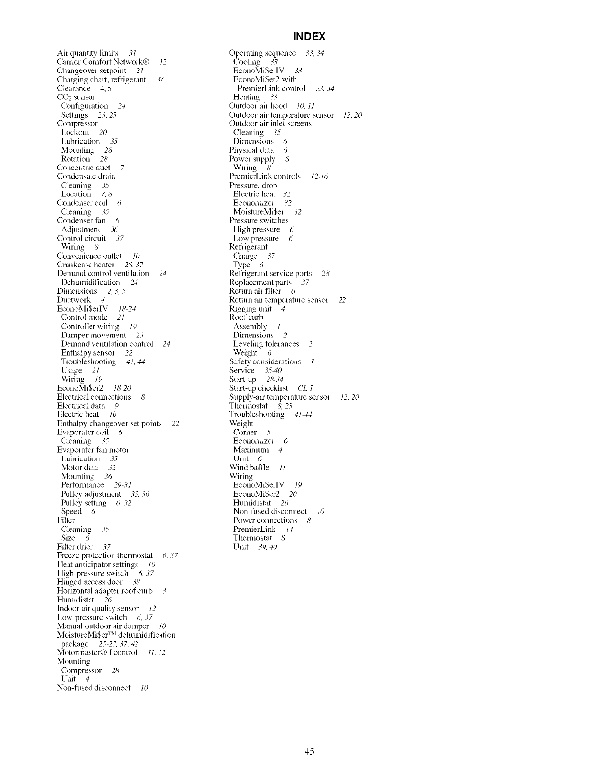
Air quantity limits 31
Carrier Comfort Network® 12
Changeover setpoint 21
Charging chart, refrigerant 37
Clearance 4, 5
CO2 sensor
Configuration 24
Settings 23, 25
Compressor
Lockout 20
Lubrication 35
Mounting 28
Rotation 28
Concentric duct 7
Condensate drain
Cleaning 35
Location 7, 8
Condenser coil 6
Cleaning 35
Condenser tim 6
Ac[iustment 36
Control circuit 37
Wiring 8
Convenience outlet 10
Crankcase heater 28, 37
Demand control ventilation 24
Dehumidification 24
Dfinensions 2, 3, 5
DuctwoN 4
EconoMiSerIV 18-24
Control mode 21
Controller wiring 19
Damper movement 23
Demand ventilation control 24
Enthalpy sensor 22
Troubleshooting 41, 44
Usage 21
Wiring 19
EconoMiSer2 18-20
Electrical connections 8
Electrical data 9
Electric heat 10
Enthalpy changeover set points 22
Evaporator coil 6
Cleaning 35
Evaporator fan motor
Lubrication 35
Motor data 32
Mounting 36
Performance 29-31
Pulley adjustment 35, 36
Pulley setting 6, 32
Speed 6
Filter
Cleaning 35
Size 6
Filter drier 37
Freeze protection thermostat 6, 37
Heat anticipator settings 10
High-pressure switch 6, 37
Hinged access door 38
Horizontal adapter roof curb 3
Humidistat 26
Indoor air quality sensor 12
Ix_w-pressure switch 6, 37
Manual outdoor air damper 10
MoistureMiSer TM dehumidification
package 25-2Z 37, 42
Motormaster® I control 11, 12
Mounting
Compressor 28
Unit 4
Non-fused disconnect 10
INDEX
Operating sequence 33, 34
Cooling 33
EconoMi$erlV 33
EconoMi$er2 with
PremierLinkcontrol 33,34
Heating 33
Outdoor air hood lO, 11
Outdoor air temperature sensor 12,20
Outdoor air inlet screens
Cleaning 35
Dimensions 6
Physical data 6
Power supply 8
Wiring 8
PmmierLink controls 12-16
Pressure, drop
Electric heat 32
Economizer 32
MoistureMiSer 32
Pressure switches
High pressure 6
Low pressure 6
Refrigerant
Cha_e 37
Type 6
Refrigerant sel_,ice ports 28
Replacement parts 37
Return air filter 6
Return air temperature sensor 22
Rigging unit 4
Roof curb
Assembly 1
Dimensions 2
Leveling tolerances 2
Weight 6
Safety considerations 1
Sew,ice 35-40
Start-up 28-34
Start-up checklist CL-1
Supply-air temperature sensor 12, 20
Thermostat 8, 23
Troubleshooting 41-44
Weight
Corner 5
Economizer 6
Maximum 4
Unit 6
Wind baffle 11
Wiring
EconoMi$erIV 19
EconoMi$er2 20
Humidistat 26
Nou-fused disconnect 10
Power connections 8
PremierLink 14
Thermostat 8
Unit 39, 40
45
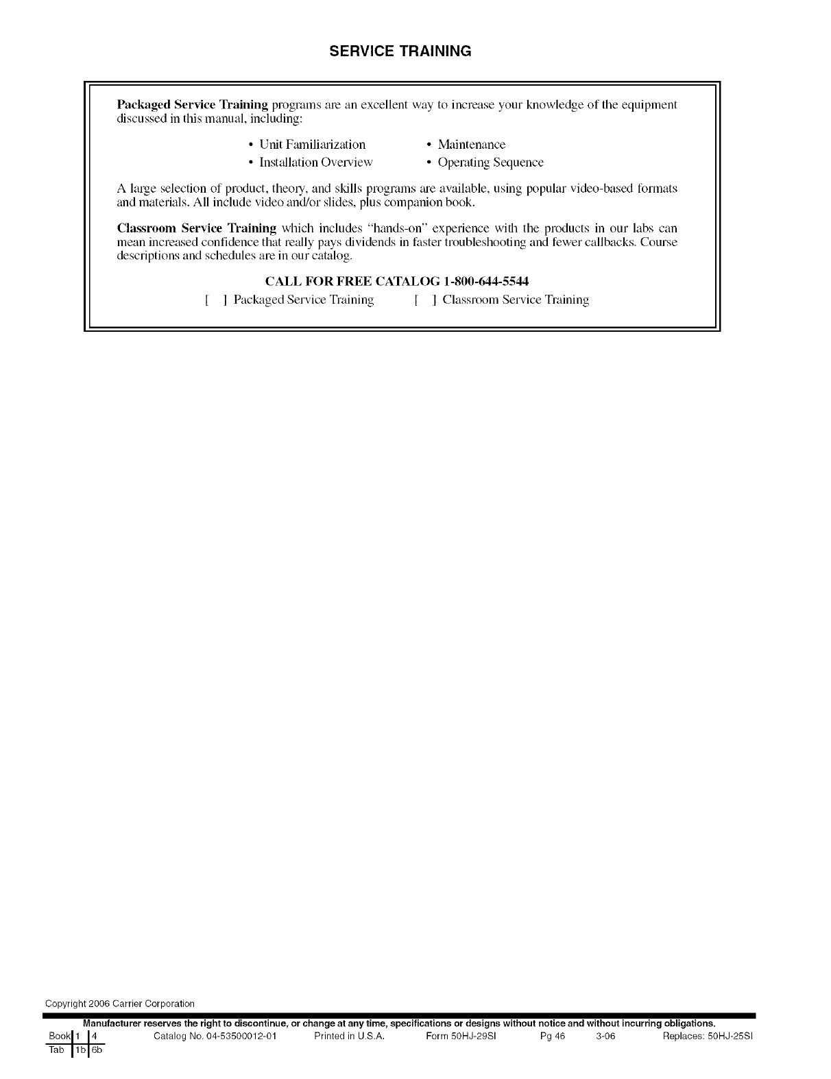
SERVICE TRAINING
Packaged Service Training programs ate an excellent way to increase your knowledge of the equipment
discussed in this manual, including:
• Unit Fmnilimization
• InstCdlation Overview
• Maintenance
• Operating Sequence
A large selection of product, theoty, and skills programs ;u'e available, using popular video-based formats
and materials. All include video and/or slides, plus companion book.
Classroom Service Training which includes "hands-on" experience with the products in our labs can
mean increased confidence thai really pays dividends in faster troubleshooting and fewer callbacks. Course
descriptions and schedules are in our catalog.
CALL FOR FREE CATALOG 1-800-644-5544
I Packaged Service Training [ I Classroom Service Training
Copyright 2006 Carrier Corporation
Manufacturer reserves the right to discontinue, or change at any time, specifications or designs without notice and without incurring obligations.
Catalog No. 04-53500012-01 Printed in U.S.A. Form 50HJ-29SI Pg 46 3-06 Replaces: 50HJ-25SI

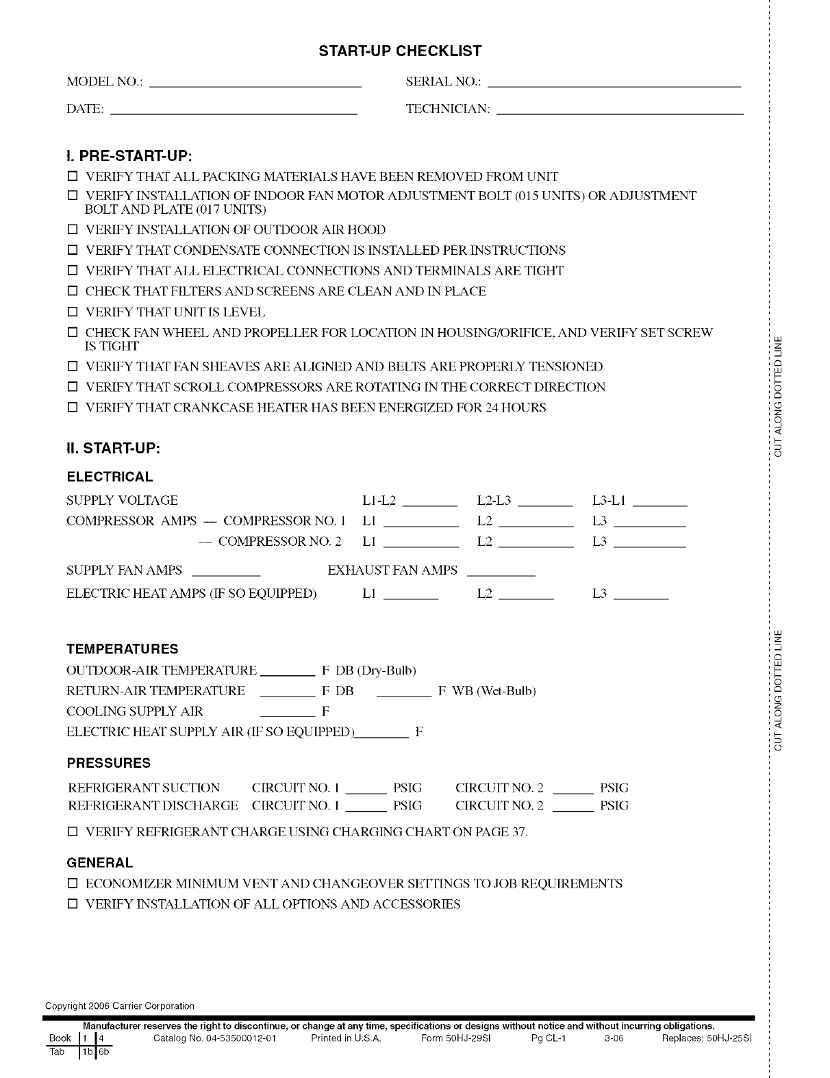
MODEL NO.:
DATE:
START-UP CHECKLIST
SERIAL NO.:
TECHNICIAN:
I. PRE-START-UP:
[] VERIFY THAT ALL PACKING MATERIALS HAVE BEEN REMOVED FROM UNIT
[] VERIFY INSTALLATION OF INDOOR FAN MOTOR ADJUSTMENT BOLT (015 UNITS) OR ADJUSTMENT
BOLT AND PLATE (017 UNITS)
[] VERIFY INSTALLATION OF OUTDOOR AIR HOOD
[] VERIFY THAT CONDENSATE CONNECTION IS INSTALLED PER INSTRUCTIONS
[] VERIFY THAT ALL ELECTRICAL CONNECTIONS AND TERMINALS ARE TIGHT
[] CHECK THAT FILTERS AND SCREENS ARE CLEAN AND IN PLACE
[] VERIFY THAT UNIT IS LEVEL
[] CHECK FAN WHEEL AND PROPELLER FOR LOCATION IN HOUSING/ORIFICE, AND VERIFY SET SCREW
IS TIGHT
[] VERIFY THAT FAN SHEAVES ARE ALIGNED AND BELTS ARE PROPERLY TENSIONED
[] VERIFY THAT SCROLL COMPRESSORS ARE ROTATING IN THE CORRECT DIRECTION
[] VERIFY THAT CRANKCASE HEATER HAS BEEN ENERGIZED FOR 24 HOURS
II. START-UP:
ELECTRICAL
SUPPLY VOLTAGE
COMPRESSOR AMPS -- COMPRESSOR NO. 1
-- COMPRESSOR NO. 2
LI-L2 L2-L3 L3-LI
LI L2 L3
LI L2 L3
SUPPLY FAN AMPS EXHAUST FAN AMPS
ELECTRIC HEAT AMPS (IF SO EQUIPPED) Ll L2 L3
TEMPERATU RES
OUTDOOR-AIR TEMPERATURE F DB (Dry-Bulb)
RETURN-AIR TEMPERATURE F DB
COOLING SUPPLY AIR F
ELECTRIC HEAT SUPPLY AIR (IF SO EQUIPPED)_ F
F WB (Wet-Bulb)
PRESSURES
REFRIGERANT SUCTION CIRCUIT NO. I PSIG CIRCUIT NO. 2
REFRIGERANT DISCHARGE CIRCUIT NO. 1 PSIG CIRCUIT NO. 2
[] VERIFY REFRIGERANT CHARGE USING CHARGING CHART ON PAGE 37.
PSIG
PSIG
GENERAL
[] ECONOMIZER MINIMUM VENT AND CHANGEOVER SETTINGS TO JOB REQUIREMENTS
[] VERIFY INSTALLATION OF ALL OPTIONS AND ACCESSORIES
Copyright 2006 Carrier Corporation
Manufacturer reserves the right to discontinue, or change at any time, specifications or designs without notice and without incurring obligations.
Book 1 14 Catalog No, 04-53500012-01 Printed in U.S,A. Form 50HJ-29SI Pg CL-1 3-06 Replaces: 50HJ-25SI
Tab 1b 16b
LU
2:
m
c_
LU
I--
rm
Z
o,
<
I-
(p
LU
2:
m
rm
LU
I-
c_
Z
o,
<
I-
(p
