CARRIER Air Conditioner/heat Pump(outside Unit) Manual L0611346
User Manual: CARRIER CARRIER Air conditioner/heat pump(outside unit) Manual CARRIER Air conditioner/heat pump(outside unit) Owner's Manual, CARRIER Air conditioner/heat pump(outside unit) installation guides
Open the PDF directly: View PDF ![]() .
.
Page Count: 4
50ZHA
Single-Package Heat Pump Units
AGuide To Operating and Maintaining Your
Single-Package Heat Pump Unit
HEATING & COOLING
ELECTRICAL SHOCK HAZARD
Failure to Ii_llow this warning could result in personal injury,
death.
Bef_re perlk)rming recoimnended maintenance, be sure the
main power switch to unit is turned olT.
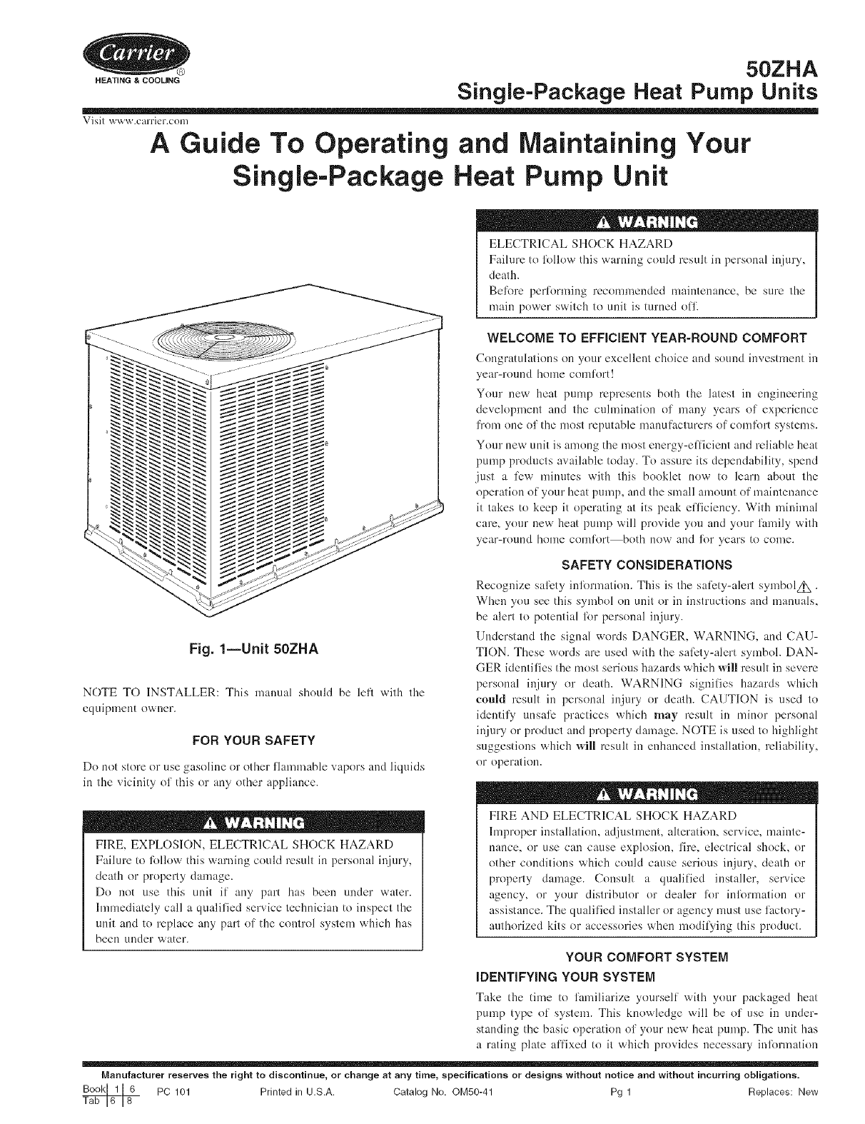
Fig. 1--Unit 50ZHA
NOTE TO INSTALLER: This manual shouM be lefl with the
equipment owner.
FOR YOUR SAFETY
Do not slore or use gasoline or other flauunable vapors and liquids
in the vicini{y of this or any odler appliance.
FIRE, EXPLOSION, ELECTRICAL SHOCK HAZARD
Failure to lbllow this warning could result in personal injury,
death or properly damage.
Do not use this unit if any part has been under water.
hnmediately call a qualified service technician to inspect the
unit and to replace any part of the control system which has
been under water.
WELCOME TO EFFiCiENT YEAR-ROUND COMFORT
Congratulations on your excellent choice and sound investment in
year-round home comlk_rt!
Your new heat pump represents both the latest in engineering
development and the cuhnination of many years of experience
from one of the most reputable manuIk_cturers of comlk_rt systems.
Your new unit is among the most energy-efficient and reliable heat
pump products available today. To assure its dependability, spend
just a li:w minutes with this booklet now to learn about the
operation of your heat pump, and the small amount of maintenance
it takes to keep it operating at its peak elTiciency. With minimal
care, your new heat pump will provide you and your family with
year-round home comlk)rt both now and lk_r years to come.
SAFETY CONSiDERATiONS
Recognize salEty inlk)rmatiou. This is the sali_ty-alert symbolz_.
When you see this symbol on unit or in instructions and manuals,
be alert to potential lbr personal injury.
Understand the signal words DANGER, WARNING, and CAU-
TION. These words are used with the sali_ty-alert symbol. DAN-
GER identifies the most serious hazards which will result in severe
personal injury or death. WARNING signifies hazards which
eoMd result in personal injury or deadl. CAUTION is used to
identify unsalE practices which may result in minor personal
injury or product and property damage. NOTE is used to highlight
suggestions which will result in enhanced installation, reliability,
or operation.
FIRE AND ELECTRICAL SHOCK HAZARD
Improper installatiom adjustment, alteration, service, mainte-
nance, or use can cause explosiom fire, electrical shocL or
other conditions which could cause serious injury, death or
properly damage. Consult a qualified installer, service
agency, or your distributor or dealer lk_r inlk_nnation or
assistance. The qualified installer or agency must use factory-
authorized kits or accessories when modilying this product.
YOUR COMFORT SYSTEM
iDENTIFYiNG YOUR SYSTEM
Take the time to familiarize yonrself with your packaged heat
pump type of systenL This knowledge will be of use in under-
standing the basic operation of your new heat pnmp. The unit has
a rating plate affixed to it which provides necessary inlkmnation
Manufacturer reserves the right to discontinue, or change at any time, specifications or designs without notice and without incurring obligations.
PC 101 Printed in U.S.A. Catalog No. ©M50-41 Pg 1 Replaces: New
lkwspecific identification of a unit. You should lkuniliafize yoursell'
with the product, model, and serial numbers listed on each rating
plate. Record them lkwlinure reli:rence in the space provided at the
end of this booklet.
iMPORTANT FACTS
To better protect your investn-lent and to eliminate unnecessary
calls_ familiarize yourself with the lollowing facts:
1. Your heat pump system should never be operated without a
clean air filter properly installed. Plan to inspect the filter
periodically. A clogged air filter will increase operating costs
and shorten the life ol' the unit.
2. Supply-air and return-air registers should not be blocked.
Drapes, limfiture, and toys are some o1' the items commonly
lound obstructing registers. Restricted airflow lessens the
unit's efl'iciency and lili: span.
3. The outdoor unit must have unrestficted airflow. Do not cover
the unit, lean anything against it, or stand on it. Do not allow
grass clippings, leaves, or other debris to accumulate around
on top of the unit. Maintain a 30-in. nfininmm clearance
between the outdoor unit and tall grass, vines, shrubs, etc.
4. Your nmltipurpose indoor tllermostal is the control center lkw
your beat pump system. You should familiarize yourself with
its proper operation. Attempting to control the system by other
n'aeans liar instance, switching the electrical supply power
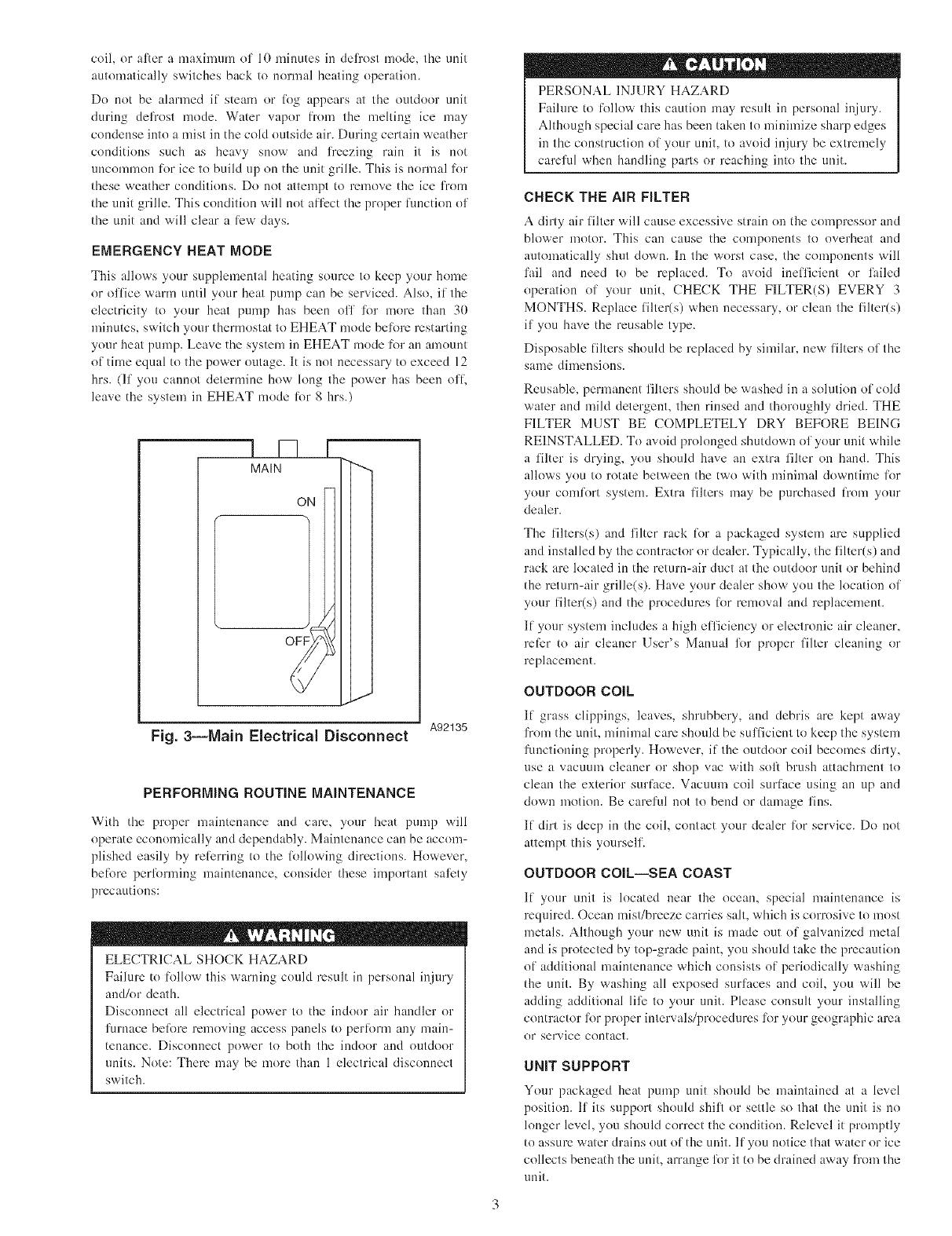
ON and OFF may cause damage to the unit (See Fig. 3).
5. Dufing heating, increasing the thermostat setting n'aorethan 2
degrees may cause the supplemental beaters to be turned on
lor a short period ol' time to satisfy the thermostat. Needless
use of the supplementary heat reduces potential energy sav-
ings.
6. You may find that you can maintain greater personal condort
by running the fan continuously. "Air pockets" can lbrna due
to the structure of the house, placement of registers, etc. air
pockets may be too cool or warm lot your liking. Continuous
lira operation minimizes any temperature dil'R:rences. Also,
systems equipped with electronic or mechanical air cleaners
and/or humidifiers ofler the added benefits ol' having the air
continuously cleaned year-round and humidified during the
winter season.
7. Your heat pump will remove bumidity fi'om your home during
the cooling season. Al_er a R:w minutes of operation, you
should be able to see water trickle from the condensate drain.
Check this occasionally to be stare the drain system is not
clogged. OI' course, don't expect to see much drainage if you
live in a very dry environment.
8. During the beating cycle, air fi'om your registers may seem
cooler than you ndght first expect. This is because your beat
pump delivers a constant flow ol' air at around 90"F to 105°F
instead of sudden bursts ol' hot air as with a conventional
liarnace. This air may leel cooler because it is slightly less than
your skin temperature. However, it is sufl'iciently warm to
keep you comlk_llable.
9. Ice or frost will tend to lkwm on the coil during the winter
beating operation. Your heat pump is designed to automati-
cally melt the ice. When in this defi'ost cycle, it is normal lk_r
steam or ling to rise fi'om the outdoor unit. Do not be alarmed!
10. Do not operate your unit in cooling mode when outdoor
temperatures are below 55"F unless your unit was naodified lkw
low-ambient operation.
11. Do not operate your unit in heating mode when outdoor
temperatures are above 66°F unless you set your thermostat to
emergency beat mode.
FIRE AND ELECTRICAL HAZARD
Failure to lk}llow this warning could result in personal injury,
death and/or property damage.
To prevent serious injury, deafll, or property dan'mge, read
and li_llow all instructions and warnings, including labels
shipped with or attached to unit beli.we operating your new
heat pump.
OPERATING YOUR HEAT PUMP
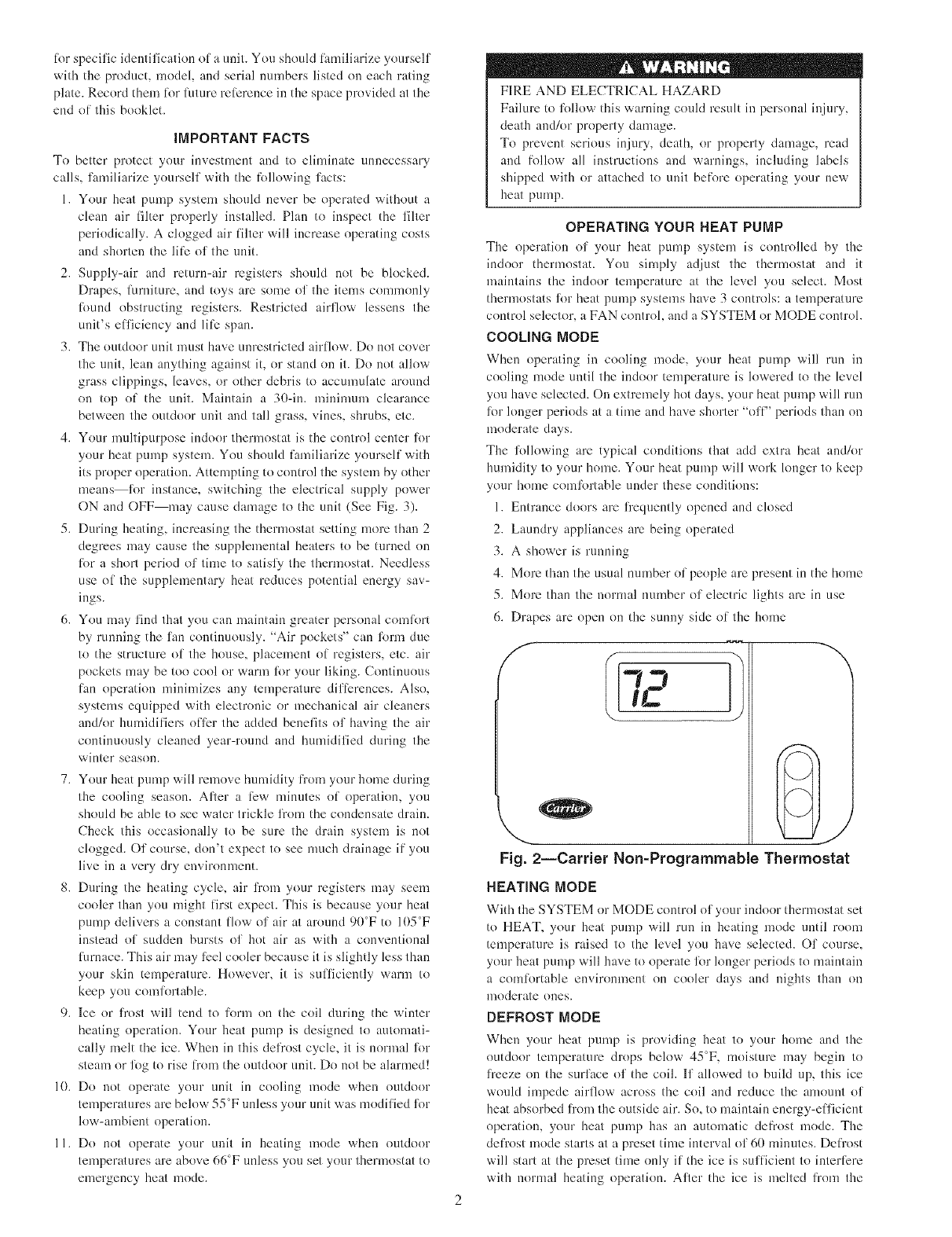
The operation of your heat pump system is controlled by the
indoor thermostat. You simply adjust the thermostat and it
maintains the indoor temperature at the level you select. Most
thermostats l_)r beat pump systems have 3 controls: a tenaperature
control selector, a FAN control, and a SYSTEM or MODE controh
COOLING MODE
When operating in cooling mode, your heat pump will run in
cooling mode until the indoor temperature is lowered to the level
yon have selected. On extremely hot days, your beat pump will run
li_)rlonger periods at a time and have shorter "ofP' periods than on
moderate days.
The li_llowing are typical conditions that add extra beat andk)r
humidity to your home. Your heat pump will work longer to keep
your home comfortable under these conditions:
1. Entrance doors are fi'eqnently opened and closed
2. Laundry appliances are being operated
3. A shower is running
4. More than the usual number of people are present in the bonae
5. More than the nornml number ol_electric lights are in use
6. Drapes are open on the sunny side of the home
f "x
Fig. 2--Carrier Non-Programmable Thermostat
HEATING MODE
With the SYSTEM or MODE control oI: your indoor thermostat set
to HEAT, your heat pump will run in heating mode until room
temperature is raised to the level you have selected. Of course,
your heat pump will have to operate for longer periods to nmintain
a comlkwtable environment on cooler days and nights than on
naoderate olaes.
DEFROST MODE
When your beat pump is providing heat to your home and the
outdoor temperature drops below 45"F_ moisture may begin to
freeze on the surface of the coil. If allowed to build tap, this ice
would impede airflow across the coil and reduce the amount of
heat absorbed fi'om the outside air. So, to maintain energy-efl'icient
operation, your beat pump has an automatic defi'ost mode. The
defi'ost mode starts at a preset time interval ol' 60 minutes. Defi'ost
will start at the preset time only if the ice is sufficient to interlcre
with normal heating operation. After the ice is melted fi'om the
coil, or after a maximum of 10 minutes in defi'ost mode, tile unit
automatically switches back to normal beating operation.
Do not be alarmed if steam or li)g appears at tile outdoor trait
during defrost mode. Water vapor fixm_ the melting ice may
condense into a mist in the cold outside air. During certain weather
conditions such as heavy snow and freezing rain it is not
uncommon lor ice to build up on the unit grille. This is normal lk)r
these weather conditions. Do not attempt to remove the ice from
the unit grille. This condition will not al]i_ct the proper l_lnction of
the unit and will clear a li_w days.
EMERGENCY HEAT MODE
This allows your supplemental beating source to keep your home
or office warm until your beat pump can be serviced. Also, if the
electricity to your heat pump has been off' lk_r more than 30
minutes, switch your thermostat to EHEAT mode beli_re restarting
your heat pump. Leave the system in EHEAT mode liar an amount
of time equal to the power outage. It is not necessary to exceed 12
hrs. (If you cannot determine how long the power has been off,
leave the system in EHEAT mode lor 8 hrs.)
! N I
MAIN i
Fig. 3--Main Electdcal Disconnect A92135
PERFORMING ROUTINE MAINTENANCE
With tile proper maintenance and care, your beat ptunp will
operate ecnnondcally and dependably. Maintenance can be accom-
plished easily by reli:rring to tile lbllowing directions. However,
belbrc perlbrming maintenance, consider these important sali_ty
precautions:
t , °
ELECTRICAL SHOCK HAZARD
Failure to lollow this warning could result in personal injury
and/or death.
Disconnect all electrical power to the indoor air handler or
furnace belorc removing access panels to perlorm any main-
tenance. Disconnect power to both the indoor and outdoor
units. Note: Them may be more than 1 electrical disconnect
switch.
PERSONAL INJURY HAZARD
Failure to ff)llow this caution may result in personal injury.
Although special care has been taken to minimize sharp edges
in tile construction of your uniL to avoid injury be extremely
careful when handling parts or reaching into the unit.
CHECK THE AiR FILTER
A dirty air filter will cause excessive strain on the compressor and
blower motor. This can cause the colnpnnenls to overheat and
antomatically shut down. In the worst case, the components will
fail and need to be replaced. To avoid inel]'icient or failed
operation of your unit, CHECK THE FILTER(S) EVERY 3
MONTHS. Replace filter(s) when necessary, or clean the filter(s)
if you have the reusable type.
Disposable filters should be replaced by similar, new filters of the
same dimensions.
Reusable, permanent filters should be washed in a solution of cold
water and mild detergent, then rinsed and thoroughly dried. THE
FILTER MUST BE COMPLETELY DRY BEFORE BEING
REINSTALLED. To avoid prolonged shutdown of your unit while
a filter is drying, yon should have an extra filter on baud. This
allows you to rotate between tile two with minimal downtime lk)r
your comlk)rt system. Extra filters may be purchased fi'om your
dealer.
The filters(s) and filter rack l_)r a packaged system are supplied
and installed by the contractor or dealer. Typically, tile filterIs) and
rack are located in the return-air duct at the outdoor unit or behind
the return-air grille(s). Have your dealer show you tile location of
your filter(s) and the procedures lk)r mmoval and replacement.
If your system includes a high elTiciency or electronic air cleaner,
relbr to air cleaner User's Manual lk)r proper filter cleaning or
replacement.
OUTDOOR COiL
If grass clippings, leaves, shrubbery, and debris are kept away
from the unit, minimal care should be sul'f]cient to keep the system
functioning properly. However, if the outdoor coil becomes dirly,
use a vacuum cleaner or shop vac with soft brush attachment to
clean the exterior surlace. Vacuum coil surface using an up and
down motion. Be careful not to bend or damage fins.
If dirt is deep in the coil, contact your dealer li)r service. Do not
attempt this yourself.
OUTDOOR COIL--SEA COAST
If your unit is located near the ocean, special maintenance is
required. Ocean mist/breeze carries salt, which is corrosive to most
metals. Although your new unit is made out of galvanized metal
and is protected by top-grade paint, you should take the precaution
of additional maintenance which consists of periodically washing
the unit. By washing all exposed surR_ces and coil, you will be
adding additional lili_ to your unit. Please consult your installing
contractor Ibr proper intervals/procedures liar your geographic area
or service contact.
UNiT SUPPORT
Your packaged heat pump unit should be maintained at a level
position. If its support should shift or settle so that the unit is no
longer level, you should correct the condition. Relevel it promptly
to assure water drains out of the unit. If you notice that water or ice
collects beneath the unit, arrange li)r it to be drained away fi'om the
unit.
BEFORE YOU REQUEST A "SERVICE CALL"
CHECK FOR THESE EASILY SOLVED PROBLEMS:
1. Check tile indoor and outdoor disconnect switches. Verify that
circuit breakers are ON or thai fuses have not blown.
2. Check lbr snfficient airflow. Check the air filter(s) lbr any
accnmulations of dirt. Check lot blocked return-air or snpply-
air registers. Be sure registers are open and unobstructed.
3. Check the settings on your indoor thermostat. If yon desire
cooling, make sure that the temperature control selector is set
below room telnperaUlre and the SYSTEM or MODE control
is set to COOL or AUTO. If you require warmth, make sure
that the ten_perature control selector is set above room
temperature and the SYSTEM or MODE control is set to
HEAT or AUTO. The FAN control should be set to ON lot
continuous blower operation or AUTO if you wish blower to
lhnction only while your heat pump is operating. If your
comlort system still fails to operate, turn your system off and
contact your servicing dealer for troubleshooting and repairs.
Specify your apparent probleln, and state the model and serial
number of your equipment. (You should have them recorded
on the last page of this booklet.) With this inlimnation, your
dealer may be able to oflcr helplid suggestions over the phone
or save valuable time through knowledgeable preparation li,_r
the service call.
REGULAR DEALER MAINTENANCE
In addition to the routine maintenance that you perlorm, your
home comlk_rt system should be inspected regularly by a properly
trained service technician. The inspection (prelbrably twice each
year, but at least once every year) should include the lollowing:
1. Routine inspection of air filter(s). Replacement or cleaning as
required.
2. Inspection and cleaning of the blower wheel, housing, and
motor as required.
3. Inspection and, if require& cleaning of coils.
4. A check of all electrical wiring and connections.
5. A check lbr secure physical connections of individual com-
ponents within unit.
6. Operational check of the heat primp system to determine
actual working condition. Necessary repair andk)r ad,iustment
should be pert'orn_ed at this time.
7. Your servicing dealer may oflcr an economical service con-
tract that covers seasonal inspections. Ask lbr fllrther details.
WARRANTIES
You have purchased a 50ZHA series unit. Be sure to read the
warranty at the back of this booklet carefully to determine the
coverage liar your unit.
FOR THE RECORD
Record the model, product, and serial uumbers of your ne'w
equipment in the spaces provided. This inlbrmation, along with the
other ready-relL'rence facts requested will be necessary should you
ever require inlbrmation or service.
iNSTALLATiON DATA
Date Installed ..................................................................................
Dealer's Name .................................................................................
Address ............................................................................................
State/Zip ..........................................................................................
Telephone ........................................................................................
UNiT DATA
Unit Model ......................................................................................
Unit Serial Number ........................................................................
Heater, if applicable:
Part Number ...................................................................................
Kilowatt Rating ..............................................................................
Copyright 2005 CARRIER Corp. • 7310 W. Morris St. •Indianapolis, IN 46231
Manufacturer reserves the right to discontinue, or change at any time, specifications or designs without notice and without incurring obligations.
B°°k 1L_L__ PC 101 Printed in U.S.A. Catalog No. OM50-41 Pg 4 Replaces: New
Tab 16 18
