CARRIER Evaporator Coils Manual L0711033
User Manual: CARRIER CARRIER Evaporator Coils Manual CARRIER Evaporator Coils Owner's Manual, CARRIER Evaporator Coils installation guides
Open the PDF directly: View PDF ![]() .
.
Page Count: 4
Installation Instructions
NOTE: Read the entire instruction manual before starting the
installation.
TABLE OF CONTENTS
PAGE
SAFETY CONSIDERATIONS ......................... 1
INTRODUCTION ................................... 1
INSTALLATION .................................... 2
Inspect Equipment ............................... 2
Select Installation ................................ 2
Installation of Evaporator Coils ...................... 2
Connect Refrigerant Piping ......................... 3
Connect Lines ................................... 3
Refrigerant Metering Device ........................ 4
Make Condensate Drain Line Connection .............. 4
SAFETY CONSIDERATIONS
Improper installation, adjustment, alteration, service, maintenance.
or use can cause explosion, fire, electrical shock or other conditions
which may cause personal injury or property damage. Consult a
qualified installer, service agency, or your distributor or branch for
information or assistance. The qualified installer or agency must
use factory-authorized kits or accessories when modifying this
product. Refer to the individual instructions packaged with the kits
or accessories when installing.
Follow all safety codes. Wear safety glasses and work gloves. Use
quenching cloths for brazing operations. Have fire extinguisher
available. Read these instructions thoroughly and follow all
warnings or cautions attached to the unit. Consult local building
codes and National Electrical Codes (NEC) for special
requirements.
It is important to recognize safety information. This is the
safety-alert symbol /_ . When you see this symbol on the unit and
in instructions or manuals, be alert to the potential for personal
injury.
Understand the signal words DANGER, WARNING. CAUTION,
and NOTE. These words are used with the safety-alert symbol.
DANGER identifies the most serious hazards which will result in
severe personal injury or death. WARNING signifies hazards
which could result in personal injury or death. CAUTION is used
to identify unsafe practices, which may result in minor personal
injury or product and property damage. NOTE is used to highlight
suggestions which will result in enhanced installation, reliability, or
operation.
ELECTRICAL SHOCK HAZARD
Failure to follow this warning could result in personal injury
or death.
Before installing or servicing system, always turn off main
power to system. There may be more than one disconnect
switch. Turn off accessory heater power if applicable. Tag
disconnect switch with lockout tag.
PERSONAL INJURY HAZARD
Failure to follow this caution may result in personal injury.
This coil contains Nitrogen precharge of up to 15 PSI. Release
of this pressure through the center of the rubber plugs is
required before removing the plugs.
PERSONAL INJURY AND ENVIRONMENTAL
HAZARD
Failure to follow this warning could result in personal injury or
death.
Relieve pressure and recover all refrigerant before servicing
existing equipment, and before final unit disposal. Use all
service ports and open all flow-control devices, including
solenoid valves.
Federal regulations require that you do not vent refrigerant into
the atmosphere. Recover during system repair or final unit
disposal.
IMPORTANT: Nitrogen can leak out through the hole that the
needle pierced in the plugs. This does not indicate a leaking coil
nor warrant return of the coil.
INTRODUCTION
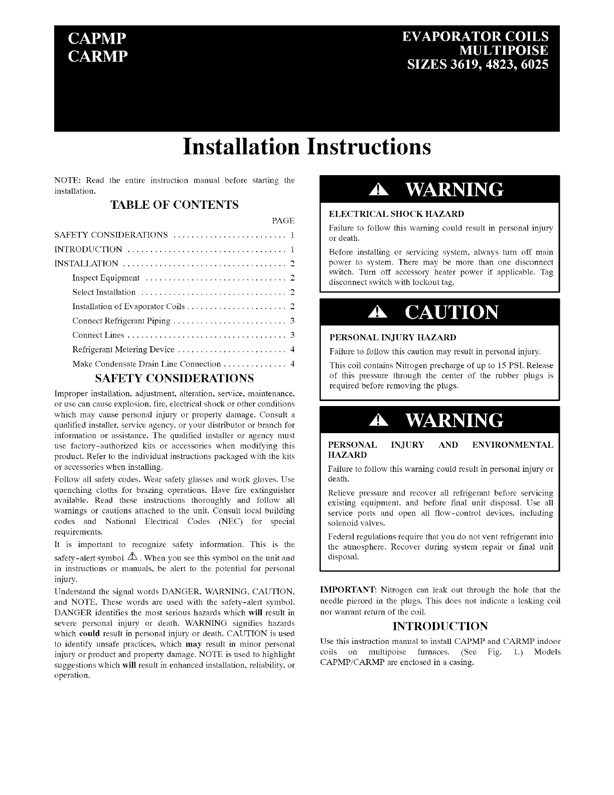
Use this instruction manual to install CAPMP and CARMP indoor
coils on multipoise furnaces. (See Fig. 1.) Models
CAPMP/CARMP are enclosed in a casing.
Supply _m"" _ Return
Supply
t
Horizontal Left Furnace hstallation
Evaporator
Coil %
Return _ Supply
Horizotlal Right R_rnace hstallation
Upfiow
Furnace
Installation
t
Return
A07737
Fig. 1- Typical Installation Multipoise Cased Coils
%
Evaporator
Coil
Return
Su_pply
Down flow
Furnace
Installation
A07738
o
Wide Coil o
Field Fabric_ed
/Adapter(s) \
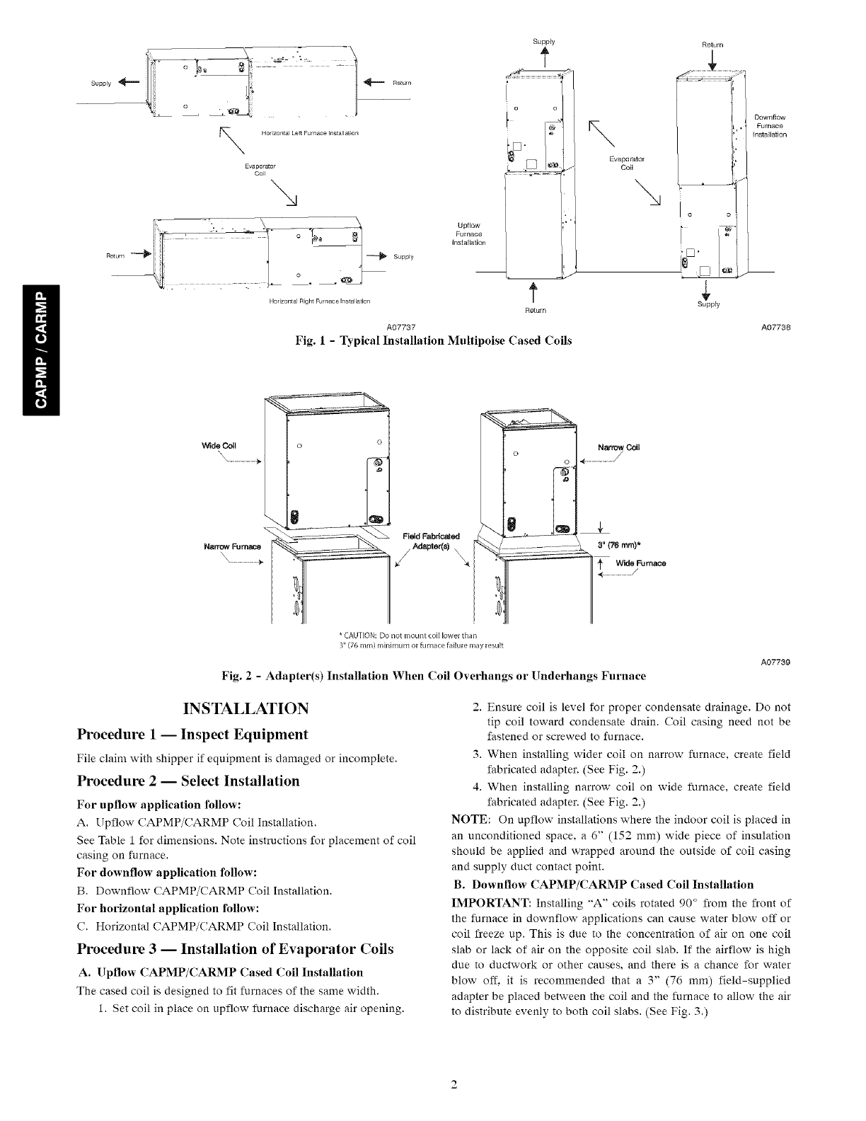
* CAUTION: Do not mount coil lower than
3" (76 ram) minimum or furnace failure may result
Narrow Coil
o
3" (76 ram)*
Fig. 2-Adapter(s) Installation When ('oil Overhangs or Underhangs Furnace
A07739
INSTALLATION
Procedure 1 -- Inspect Equipment
File claim with shipper if equipment is damaged or incomplete.
Procedure 2 -- Select Installation
For upflow application follow:
A. Upflow CAPMP/CARMP Coil Installation.
See Table 1 for dimensions. Note instructions for placement of coil
casing on furnace.
For downflow application follow-:
B. Downflow CAPMP/CARMP Coil Installation.
For horizontal application follow-:
C. Horizontal CAPMP/CARMP ('oil Installation.
Procedure 3 -- Installation of Evaporator Coils
A. Upflow CAPMP/CARMP Cased ('oil Installation
The cased coil is designed to fit furnaces of the same width.
1. Set coil in place on upflow furnace discharge air opening.
2. Ensure coil is level for proper condensate drainage. Do not
tip coil toward condensate drain. Coil casing need not be
fastened or screwed to furnace.
3. When installing wider coil on narrow furnace, create field
fabricated adapter. (See Fig. 2.)
4. When installing narrow coil on wide furnace, create field
fabricated adapter. (See Fig. 2.)
NOTE: On up flow installations where the indoor coil is placed in
an unconditioned space, a 6" (152 mm) wide piece of insulation
should be applied and wrapped around the outside of coil casing
and supply duct contact point.
B. Downflow CAPMP/CARMP Cased Coil Installation
IMPORTANT: Installing "A" coils rotated 90 ° from the front of
the furnace in downflow applications can cause water blow off or
coil freeze up. This is due to the concentration of air on one coil
slab or lack of air on the opposite coil slab. If the airflow is high
due to ductwork or other causes, and there is a chance for water
blow off. it is recommended that a 3" (76 mm) field-supplied
adapter be placed between the coil and the furnace to allow the air
to distribute evenly to both coil slabs. (See Fig. 3.)
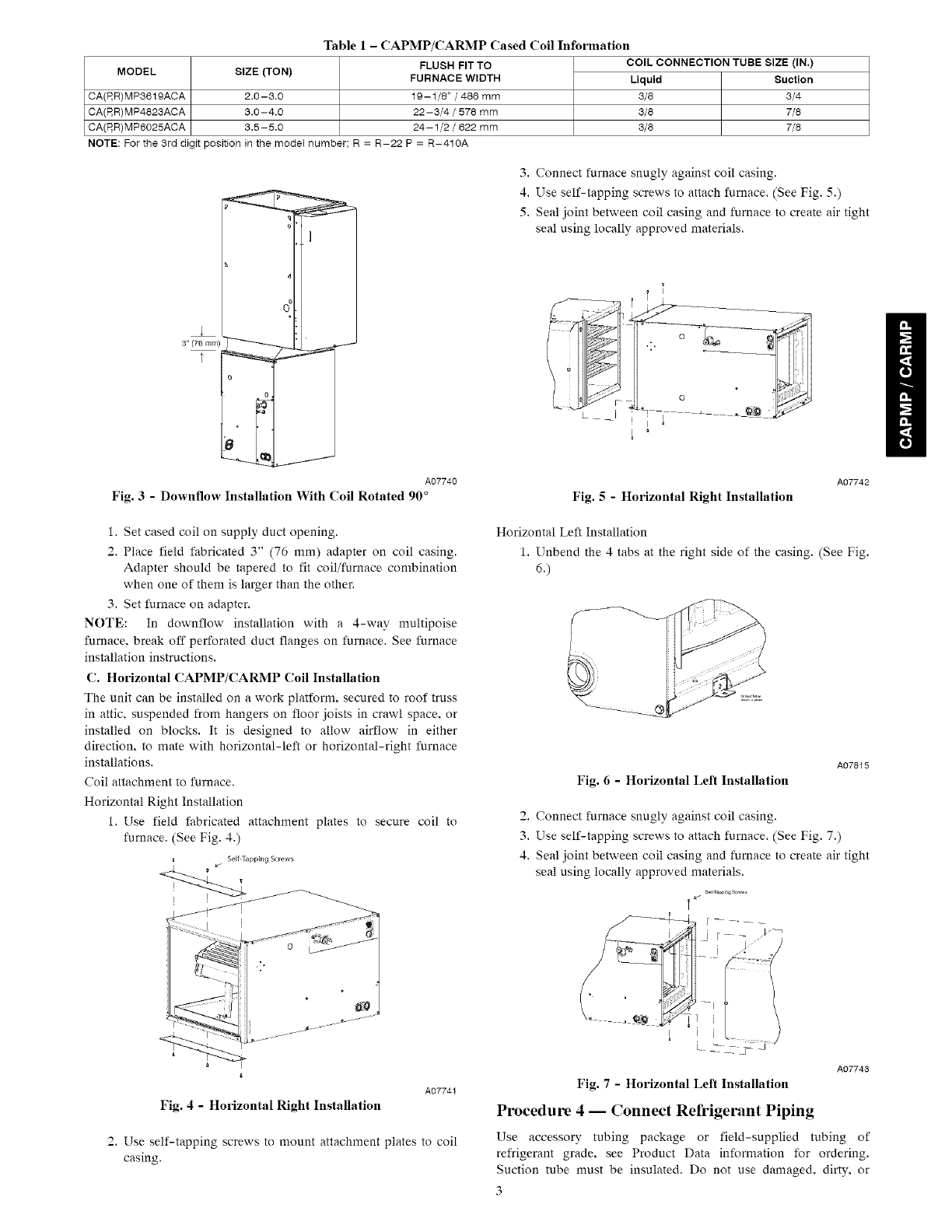
Table 1- CAPMP/CARMP Cased Coil Information
FLUSH FIT TO COIL CONNECTION TUBE SIZE (IN.)
MODEL SIZE (TON) FURNACE WIDTH Liquid Suction
CA(P,R)MP3519ACA 2.0-3.0 10-1/8" /486 mm 3/8 3/4
CA(P,R)MP4823ACA 3.0-4.0 22-3/4 /578 mm 3/8 7/8
CA(P,R)MPS025ACA 3.5-5.0 24-1/2 /622 mm 3/8 7/8
NOTE: For the 3rd digit position in the model number; R = R-22 P = R-410A
A07740
Fig. 3-Downflow Installation With Coil Rotated 90 °
3. Connect furnace snugly against coil casing.
4. Use self-tapping screws to attach furnace. (See Fig. 5.)
5. Seal joint between coil casing and furnace to create air tight
seal using locally approved materials.
Fig. 5- Horizontal Right Installation
A07742
1. Set cased coil on supply duct opening.
2. Place field fabricated 3" (76 mm) adapter on coil casing.
Adapter should be tapered to fit coil/furnace combination
when one of them is larger than the other.
3. Set furnace on adapter.
NOTE: In downflow installation with a 4-way multipoise
furnace, break off perforated duct flanges on furnace. See furnace
installation instructions.
C. Horizontal CAPMP/CARMP ('oil Installation
Tire unit can be installed on a work platform, secured to roof truss
in attic, suspended from hangers on floor joists in crawl space, or
installed on blocks. It is designed to allow airflow in either
direction, to mate with horizontal-left or horizontal-right furnace
installations.
Coil attachment to furnace.
Horizontal Right Installation
1. Use field fabricated attachment plates to secure coil to
furnace. (See Fig. 4.)
Self Tapping Screws
Horizontal Left Installation
1. Unbend the 4 tabs at the right side of the casing. (See Fig.
d.)
A07815
Fig. 6 - Horizontal Left Installation
2. Connect furnace snugly against coil casing.
3. Use self-tapping screws to attach furnace. (See Fig. 7.)
4. Seal joint between coil casing and furnace to create air tight
seal using locally approved materials.
J...... _
Fig. 4 - Horizontal Right Installation
A07741
2. Use self-tapping screws to mount attachment plates to coil
casing.
A07743
Fig. 7 -Horizontal Left Installation
Procedure 4 -- Connect Refrigerant Piping
Use accessory tubing package or field-supplied tubing of
refrigerant grade, see Product Data information for ordering.
Suction tube must be insulated. Do not use damaged, dirty, or
3
contaminatedtubingbecauseit mayplugrefrigerantflow-control
device.ALWAYSevacuatethecoilandfield-suppliedtubing
beforeopeningoutdoorunitservicevalves.
Procedure 5-- Connect Refrigerant, Liquid, and
Suction Lines
For matched and mismatched systems, use line sizes recommended
in outdoor unit Installation Instructions.
The coil can be connected to outdoor units using accessory tubing
packages or field-supplied tubing of refrigerant grade. Always
evacuate tubing and reclaim refrigerant when making connections
or flaring tubing. Leak check connections before insulating entire
suction line.
See Table 1 for coil connection tube size.
1. Remove cabinet door. Remove tubing plate with rubber
grommets and slide plate with grommets onto the
refrigerant lines (field line-set), away from braze joints.
2. Remove rubber plugs from coil stubs using a pulling and
twisting motion. Hold coil stubs steady to avoid bending or
distorting.
3. Wrap TXV and nearby tubing with a heat-sinking material
such as a wet cloth.
4. Fit refrigerant lines into coil stubs. Wrap a heat sinking
material such as a wet cloth behind braze joints.
5. Braze using a Sil-Fos or Phos-copper alloy.
6. After brazing, allow joints to cool. Slide tubing plate with
rubber grommets over joints. Position tubing at center of
each grommet to ensure an air seal around the tube.
UNIT DAMAGE HAZARD
Failure to follow this caution may result in product damage.
To avoid valve damage to the refrigerant control device while I
brazing, valves must be wrapped with a heat-sinking material
such as a wet cloth.
REFRIGERANT METERING DEVICE
CAPM Models:
These Coils have a factory installed hard shut-off TXV designed
only for use with R-410A refrigerant. Use only with outdoor units
designed for R-410A.
CARM Models:
These Coils have a factory installed hard shut-off TXV designed
only for use with R-22 refrigerant. Use only with outdoor units
designed for R-22.
NOTE: All TXV'S have preset superheat settings and are field
non-adjustable.
Procedure 6 -- Make Condensate Line
Connection
The coil is designed to dispose of accumulated water through
built-in condensate drain fitting. Two 3/4" female threaded pipe
connections are provide in each coil.
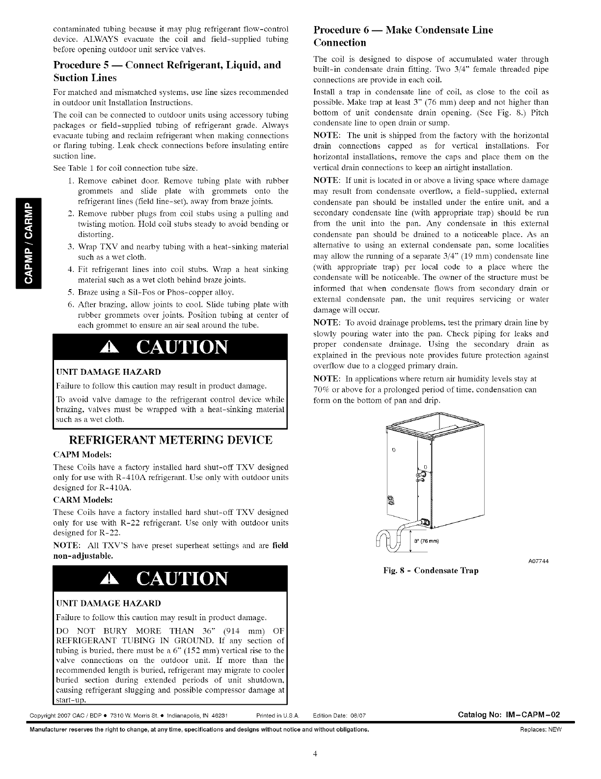
Install a trap in condensate line of coil, as close to the coil as
possible. Make trap at least 3" (76 ram) deep and not higher than
bottom of unit condensate drain opening. (See Fig. 8.) Pitch
condensate line to open drain or sump.
NOTE: The unit is shipped from the factory with the horizontal
drain connections capped as for vertical installations. For
horizontal installations, remove the caps and place them on the
vertical drain connections to keep an airtight installation.
NOTE: If unit is located in or above a living space where damage
may result from condensate overflow, a field-supplied, external
condensate pan should be installed under the entire unit, and a
secondary condensate line (with appropriate trap) should be run
from the unit into the pan. Any condensate in this external
condensate pan should be drained to a noticeable place. As an
alternative to using an external condensate pan, some localities
may allow the running of a separate 3/4" (19 mm) condensate line
(with appropriate trap) per local code to a place where the
condensate will be noticeable. The owner of the structure must be
informed that when condensate flows from secondary drain or
external condensate pan, the unit requires servicing or water
damage will occur.
NOTE: To avoid drainage problems, test the primary drain line by
slowly pouring water into the pan. Check piping for leaks and
proper condensate drainage. Using the secondary drain as
explained in the previous note provides future protection against
overflow due to a clogged primary drain.
NOTE: In applications where return air humidity levels stay at
70% or above for a prolonged period of time, condensation can
form on the bottom of pan and drip.
ram)
UNIT DAMAGE HAZARD
Failure to follow this caution may result in product damage.
DO NOT BURY MORE THAN 36" (914 mm) OF
REFRIGERANT TUBING IN GROUND. If any section of
tubing is buried, there must be a 6" (152 mm) vertical rise to the
valve connections on the outdoor unit. If more than the
recommended length is buried, refrigerant may migrate to cooler
buried section during extended periods of unit shutdown,
causing refrigerant slugging and possible compressor damage at
start-up.
Copyright 2007 CAC /BDP • 7310 W. Morris St. • _ndianapolis, iN 46231 Printed in U.SA Edition Date: 08/07
Manufacturer reserves the right to change_ at any time_ specifications and designs without notice and without obligations.
Fig. 8-Condensate Trap
A07744
Catalog No: IM-CAPM-02
Replaces: NEW
