CARRIER Package Units(both Units Combined) Manual L0801094
User Manual: CARRIER CARRIER Package Units(both units combined) Manual CARRIER Package Units(both units combined) Owner's Manual, CARRIER Package Units(both units combined) installation guides
Open the PDF directly: View PDF ![]() .
.
Page Count: 22
_rn to the Expertg
Installation Instructions
NOTE: Read the entire instruction manual before starting the
installation.
NOTE: Installer: Make sure the Owner's Manual and Service
Instructions are left with the unit after installation.
TABLE OF CONTENTS
Page
SAFETY CONSIDERATIONS ........................ 1
INTRODUCTION .................................. 2
RECEIVING AND INSTALLATION ................. 2-9
Check Equipment ................................. 2
Identify Unit ................................... 2
Inspect Shipment ................................ 2
Provide Unit Support .............................. 2
Roof Curb ..................................... 2
Slab Mount .................................... 2
Ground Mount ................................. 2
Provide Clearances ................................ 2
Field Fabricate Ductwork ........................... 2
Rig and Place Unit ................................ 2
Inspection ..................................... 6
Installation ..................................... 6
Use of Rigging Bracket ........................... 7
Connect Condensate Drain .......................... 7
Install Duct Connections ............................ 7
Configuring Units for Downflow (Vertical) Discharge ..... 8
Install Electrical Connections ........................ 8
High-Voltage Connections ........................ 9
Special Procedures for 208v Operation ............... 9
Control Voltage Connections ....................... 9
Standard Connection ............................. 9
Transformer Protection ........................... 9
PRE-START-UP .................................. 10
START-UP .................................... 11-16
Check for Refrigerant Leaks ........................ 11
Start-Up Adjustments ............................. 11
Checking Cooling Control Operation ............... 11
Checking and Adjusting Refrigerant Charge .......... 11
Indoor Airflow and Airflow Adjustments ............ 17
Cooling Sequence of Operation .................... 17
MAINTENANCE ............................... 17-19
Air Filter ....................................... 18
Indoor Blower and Motor .......................... 18
Outdoor Coil, Indoor Coil, and Condensate Drain Pan .... 18
Outdoor Fan .................................... 18
Electrical Controls and Wiring ...................... 18
Refrigerant Circuit ................................ 19
Indoor Airflow .................................. 19
Metering Devices
Thermostatic Expansion Valve .................... 19
AccuRater _5Piston ............................. 19
TROUBLESHOOTING ............................. 19
START-UP CHECKLIST ........................... 19
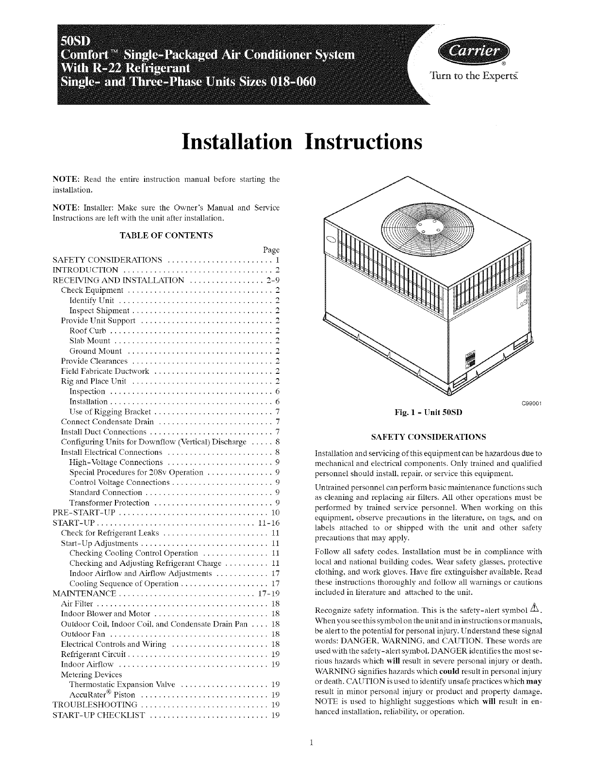
Fig. 1 - Unit 50SD
C99001
SAFETY CONSIDERATIONS
Installation and servicing of this equipment can be hazardous due to
mechanical and electrical components. Only trained and qualified
personnel should install, repair, or service this equipment.
Untrained personnel can perform basic maintenance functions such
as cleaning and replacing air filters. All other operations must be
performed by trained service personnel. When working on this
equipment, observe precautions in the literature, on tags, and on
labels attached to or shipped with the unit and other safety
precautions that may apply.
Follow all safety codes. Installation must be in compliance with
local and national building codes. Wear safety glasses, protective
clothing, and work gloves. Have fire extinguisher available. Read
these instructions thoroughly and follow all warnings or cautions
included in literature and attached to the unit.
Recognize safety information. This is the safety-alert symbol _.
When you see this symbol on the unit and in instructions or manuals,
be alert to the potential for personal injury. Understand these signal
words: DANGER, WARNING. and CAUTION. These words are
used with the safety-alert symbol. DANGER identifies the most se-
rious hazards which will result in severe personal injury or death.
WARNING signifies hazards which could result in personal injury
or death. CAUTION is used to identify unsafe practices which may
result in minor personal injury or product and property damage.
NOTE is used to highlight suggestions which will result in en-
hanced installation, reliability, or operation.
ELECTRICALSHOCKHAZARD
Failuretofollowthiswarningcouldresultinpersonalinjury
ordeath.
Beforeinstallingorservicingsystem,alwaysturnoffmain
powertosystem.Theremaybemorethanonedisconnect
switch.Turnoffaccessoryheaterpowerswitchifapplicable.
PERSONALINJURYAND ENVIRONMENTAL
HAZARD
Failuretorelievesystempressurecouldresultinpersonal
injuryand/ordeath.
1.Relievepressureandrecoverallrefrigerantbeforeservicing
existingequipment,andbeforefinalunitdisposal.Useall
serviceportsandopenallflow-controldevices,including
solenoklvalves.
2.Federalregulationsrequirethatyoudonotventrefrigerant
intotheatmosphere.Recoverduringsystemrepairorfinalunit
disposal.
INTRODUCTION
The50SDpackagedairconditionerisfullyself-containedand
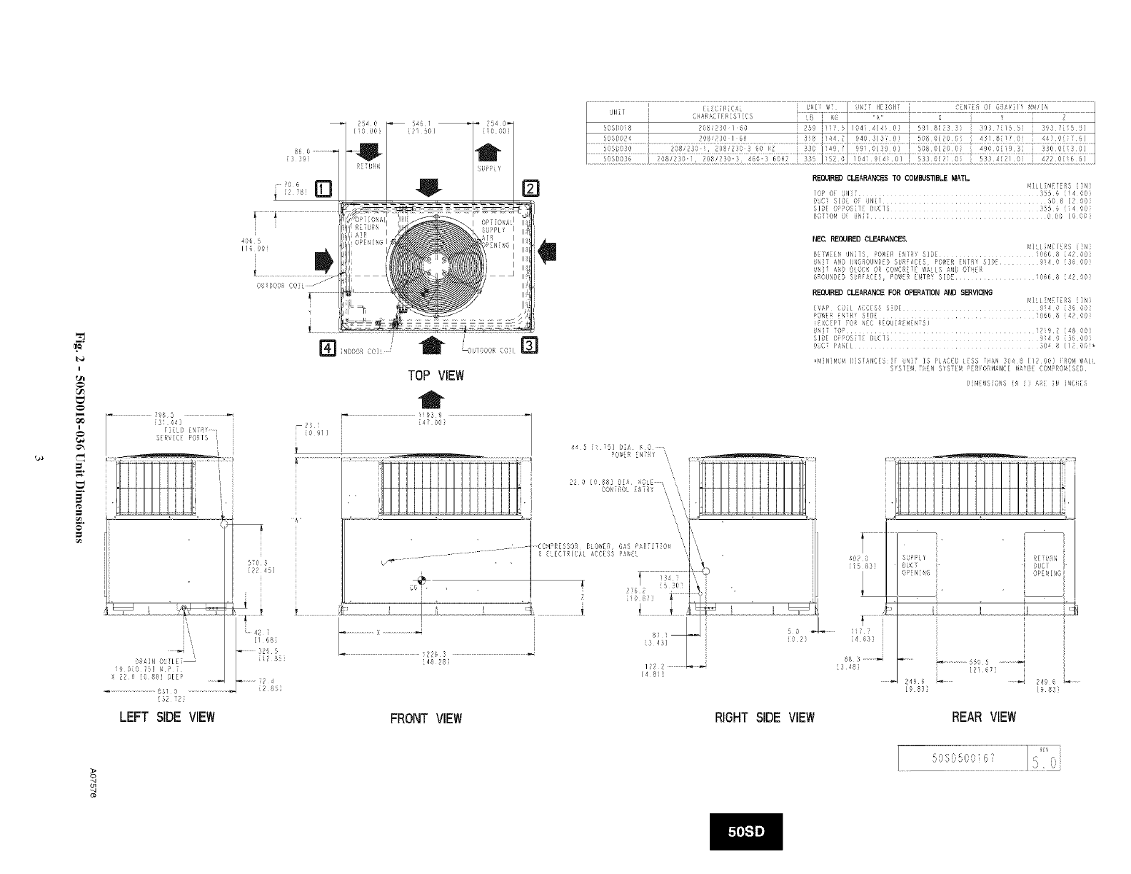
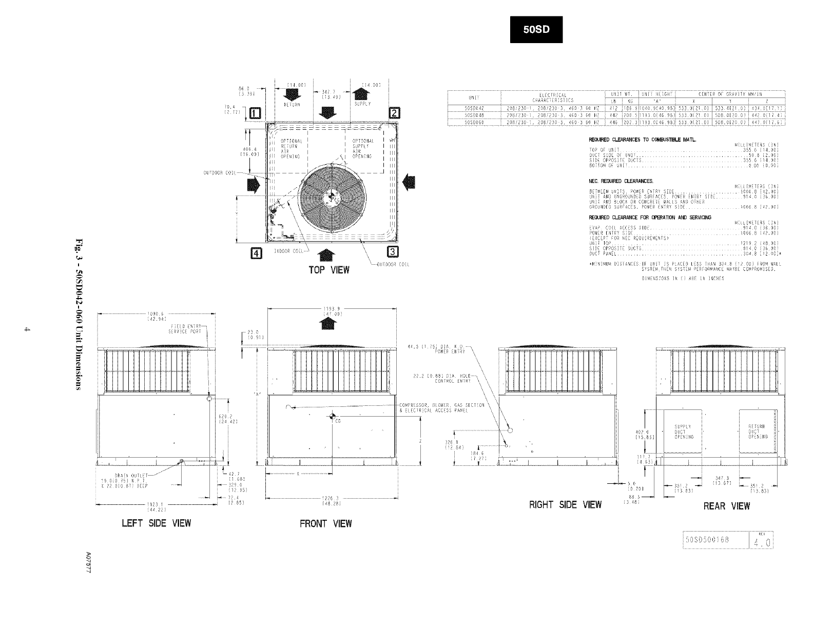
designedforoutdoorinstallation(SeeFig.1).SeeFig.2and3for
unitdimensions.Allunitsizeshavedischargeopeningsforboth
horizontalanddownflowconfigurations,andarefactoryshipped
withalldownflowductopeningscovered.Theunitmaybeinstalled
eitheronarooftop,ground-levelcementslab,ordirectlyonthe
groundiflocalcodespermit.(SeeFig.4forroofcurbdimensions.)
RECEIVINGANDINSTALLATION
Stepl--Check Equipment
IDENTIFY UNIT
The unit model number and serial number are printed on the unit
informative plate. Check this information against shipping papers.
INSPECT SHIPMENT
Inspect for shipping damage while unit is still on shipping pallet. If
unit appears to be damaged or is torn loose from its anchorage, have
it examined by transportation inspectors before removaL Forward
claim papers directly to transportation company. Manufacturer is
not responsible for any damage incurred in transit. Check all items
against shipping list. Immediately notify the nearest equipment
distribution office if any item is missing. To prevent loss or damage,
leave all parts in original packages until installation.
Step 2--Provide Unit Support
For hurricane tie downs, contact distributor for details and PE
(Professional Engineering) Certificate if required.
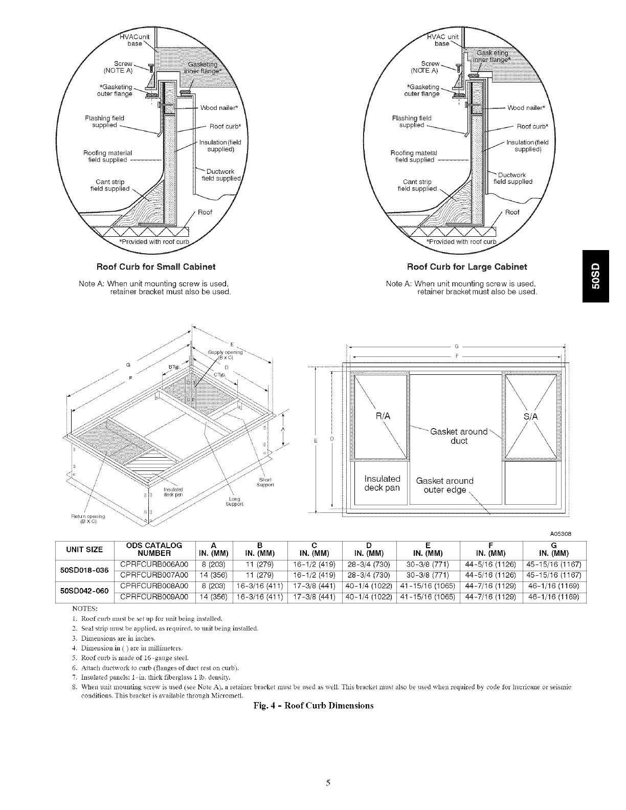
ROOF CURB
Install accessou roof curb in accordance with instructions shipped
with curb (See Fig. 4). Install insulation, cant strips, roofing, and
flashing. Ductwork must be attached to curb.
IMPORTANT: The gasketing of the unit to the roof curb is critical
for a water tight seal. Install gasketing material supplied with the
roof curb. Improperly applied gasketing also can result in air leaks
and poor unit performance.
Curb should be level to within 1/4 in. (See Fig. 6). This is necessary
for unit drain to function properly. Refer to accessory roof curb
installation instructions for additional information as required.
SLAB MOUNT
Place the unit on a solid, level concrete pad that is a minimum of 4
in. (102 mm) thick with 2 in. (51 ram) above grade. The slab should
extend approximately 2 in. beyond the casing on all 4 sides of the
unit (See Fig. 7). Do not secure the unit to the slab except when
required by local codes.
GROUND MOUNT
The unit may be installed either on a slab or placed directly on the
ground if local codes permit. Place the unit on level ground prepared
with gravel for condensate discharge.
Step 3--Provide Clearances
The required minimum service clearances are shown in Fig. 2 and
3. Adequate ventilation and outdoor air must be provided. The
outdoor fan draws air through the outdoor coil and discharges it
through the top fan grille. Be sure that the fan discharge does not
recirculate to the outdoor coil. Do not locate the unit in either a
corner or under an overhead obstruction. The minimum clearance
under apartial overhang (such as a normal house overhang) is 48 in.
(1219 ram) above the unit top. The maximum horizontal extension
of apartial overhang must not exceed 48 in. (1219 ram).
IMPORTANT: Do not restrict outdoor airflow. An air restriction at
either the outdoor-air inlet or the tim discharge may be detrimental
to compressor life.
Do not place the unit where water, ice. or snow from an overhang
or roof will damage or flood the unit. Do not install the unit on
carpeting or other combustible materials. Slab-mounted units
should be at least 4 in. (102 mm) above the highest expected water
and runoff levels. Do not use unit if it has been under water.
Step 4_Field-Fabricate Duetwork
Secure all ducts to roof curb and building structure on vertical
discharge units. Do not connect ductwork to unit. For horizontal
applications, unit is provided with flanges on the horizontal
openings. All ductwork should be secured to the flanges. Insulate
and weatherproof all external ductwork, joints, and roof openings
with counter flashing and mastic in accordance with applicable
codes.
Ducts passing through an unconditioned space nmst be insulated
and covered with a vapor barrier. If a plenum return is used on a
vertical unit. the return should be ducted through the roof deck to
comply with applicable fire codes. A minimum clearance is not
required around ductwork. Cabinet return- air static shall not exceed
-.25 in. wc.
Step 5--Rig and Place Unit
Rigging and handling of this equipment can be hazardous for many
reasons due to the installation location (roofs, elevated structures.
etc.).
Only trained, qualified crane operators and ground support staff
should handle and install this equipment.
When working with this equipment, observe precautions in the
literature, on tags, stickers, and labels attached to the equipment, and
any other safety precautions that might apply.
Training for operators of the lifting equipment should include, but
not be limited to, the following:
1. Application of the lifter to the load, and adjustment of the
lifts to adapt to various sizes or kinds of loads.
2. Instruction in any special operation or precaution.
3. Condition of the load as it relates to operation of the lifting
kit. such as balance, temperature, etc.
Follow all applicable safety codes. Wear safety shoes and work
gloves.
I-4
I
tSl
I
.=.
SERVICE PORTS
=
RAiN 0 LET
19 0(0 5] _, [
X 220 [088] DEEP
............................ 8`1/ 0 .........................
132 72i
LEFT SIDE VIEW
S,'O 3
{22 45]
4
[/ 66]
.126 5
_* 85
_ 2,
[281
5461
{21 501
REQUIRSD CLEARANCES TO COMI_JSTIBLE MATL
MILl SDTERS []14]
lOP Oi¸ UN{: ¸ 355 6 ii4 00)
DLiC SIDE CF UN:T .............................. SO 8 [2 00i
SIg[ O_?OS:T_ DUCTS }55 6 [14 00i
t_61:Or,10i D!iJI ............... 000 [O 09i
INDOOR C0] /i LOUT O")R COl []
TOP VIEW
i
,_ 195 9
2`1i i 147 003
(0 911 j
J
][.........................
44 5 il 751DZA K 0
22 0 DO 88i 91A :iOLE ,,
£ONTROL DNTR¢ ',
A
¸¸COMPRESSOR¸ B:O_[_, GAS PARTIT:O_J ",
i9 8_] ! "
.............................. _ f'!48 28 ............................... / __224 ] L_
t4 8ii
]]:l i]]
HIlIll1]LIII!JH:
NED. REO_IRED CLEARANCE& rilL[ _! I I$ {i14}
Bi1_[:/_i WiilS i>CWE[! {!iI_ ¸ SJD[ ..... 066 8 42 0,.}
U_iT _i9 U_4{,qOU_,D{9 SDRFACES POWER E!iTR! ¸ SIDE¸ 9i4 0 [36 0DI
U!i_ A_i_ i}t6(:_ O[ ¢OI481i_1: WALl D ;NO O/}iE[_
6ROUND_9 SLR_ADES, PO_ER E!i]_ ¸ SI_E ............ 1066 8 42 0R
REQUIRSD CLEARANCE FOR OPESATION AND SERVICING
MILD :_IDTERS [][41
E_AI> {O:[ !<I¢[.£S sin[¸ ........... 914 0 f _ 0 n_
PO_'_'ERiNTR_ S!n[ ........ 1,366 8 [4_ 00i
(i_,3iiFI fOR !iEC ii{OU:_iiM_N:S)
U_iii TOP ................................... 12i9 2 [48 00i
SIDE O?POS:TE DU{TS 914 0 [`16 00i
i)DCi ¸ I_N[I ............... 304 8 [/2 00]_
_!,IINIMU4 ()IS]AN¢(S 11 UN IS D{A D i:SS ::AN 30,! ! I/ '}C} IOII _1{
S!STE_4 TiiDN SYSTE_I _ER[ OR!4ANDE ,!£_B: ,30_!PRO!4TS_9
[)iM NSIO4S it il A ili INCf[
t
i5 8`1]
.... iiii
8_
88 3
[348]
SgPP[ /
,(
OPEN: G
Otl¢]
9PE ING
.I
....... _.................5505 .............
[2167]
24_ 6 _ ...... _ 24g 6 _
[9 8`1} [9 83_
FRONTVIEW RIGHTSIDE VIEW REARVIEW
o
o)
i
I
OUTDOOR
itDOOR 80 L _ /
< O[ }OOR C0ii
TOP VIEW
,? ! ii: i YrJ ],,
LNI if C/f} AI
REQUIREDCI._ARANCESTO COMBUSTIblEMATL. Mi[iJMNI_5 [Itii
TOPOF U!dT ...... 355 6 {i,108i
O_li 5iOE O{ UNli ................ 50 5 [208}
SIDE OPPOS}H:Od{T5 355 6 i/4 OOi
BONOM O_ UNli............................ 0 O0 [800i
NEC. REQUIRED CLEARANCES.
ML( ]4ET[R5
B ii_EEri @]18 ,3_iEI EtiR_ SIDE ......... 0668 {4208
UNiT Al_O UNSROU_D[O SURFAC[S P@#H_ H_[RY SIDE 914 0:6 08_
UN:i '-r_o 8LOCK OR (:or_SRE_E WAIL5 ANi) ,3iHiR
G_!OUNDEO SU_/rAC S POW{!fi iRY 5}C,f i066 8 {4Z 08i
RE_aJIREDCL,F_RANCE FIll 81"B_ATII?_ Ai_ SERVICINB
14:[i ]_4E1{:R5 ({ti}
_( P COIL A¢CES5 SIDE .... 9/4¸0 {:/6 00)
POWER [NTRY STD_ :O66 8:42OO}
(EXCEPT FOR tiE¢ REOU:REMENTS)
U_ii ¸ lOP ........... _2/9 2 i48 00}
SIDE OPPOS:TE DU¢T5 914 0 :6 O0
Od¢ N ' .......................... }04¸8 [12 80]_
_M:N:_IU_,! D}SIANCE5 ]F uri:l ]5 PLACED L_ S IHAN 304 8 [12 OOi fRO_l I_LL
5fS/E!,! /liEN 5fSTEM PEi_iORMA!iC[ MMIiI: £O!4PRO_,!}SEi)
O]_,![_iS:¢'_iS ]li i] ARE }ti }NCili5
i090 G
[4294]
[HiD N R_
5iR/lCf PORT ]
$Zo Z
24 42]
{I 68]
_Z o[o 87} DE[P _ 3290
i12 95}
....... ?s 4
i3 I _ [2 85]
[4422
LEFT SIDE VIEW
i!93 9
44 5 {/ 5] DIA K o x [:::fl_::::=::::=: 2::......
2 i0 88 A IOE _ ,
(ON OL EN ',
,,, • .
c ,P[ 55OR, i @_i AS 51¢1i04 _, _
& ELE¢IR]C!L _¢¢S PAr, I _ \\
oH | _ .
84 _ ..........
/ !/
148 8
i/,'
11....... _== f
00I
RIGHTSIDE VIEW ; _
FRONTVIEW
REUN
PLOT
4
{13 83} [1355]
REARVIEW
o>
s
q
HVAOunit
/(NOTE A) _11
/0,=4
' Wood nailer*
/Flashing field
I_I::!i:_ _nsulati°p (field
I Roofing rr, aterial It_-;!_'_II sopp,,ed>
/ '_e'ds_Pp"e_- lC_J:!IIIL
Roof Curb for SmMI Cabinet
Note A: When unit mounting screw is used,
retainer bracket must also be used.
/ ,,,_%w _.<_
/
i 1tl
' Wood nailer*
/Elasl_ing field _od nailer*
IF_ /lnsulati£p (f!eld
\ field -- -II: iitllL
Roof Curb for Large Cabinet
Note A: When unit mounting screw is used,
retainer bracket must also be used. /
Retu n opel_lrlg
(BXO)
E
Long
SuppoEt
Short
Support
A
R/A
\\ _Gasket around
\\ duct
\\
S/A
/2
Insulated Gasket around
deck pan outer edge X
\
UNIT SIZE
50SD018-036
50SD042-060
NOTES:
ODS CATALOG A B
NUMBER IN. (aM) IN. (aM)
CPRFCURBOO6AOO 8 (203) 11 (279)
CPRFCURBOO7AOO 14 (356) 11 (279)
CPRFCURBOO8AOO 8 (203) 16-3/18 (411)
CPRFCURBOO9AOO 14 (356) 16-3/16 (411)
[. Roof curb lnust be set tip for ullit being installed.
C
IN. (MM)
16-1/2 (419)
16-1/2 (419)
17-3/8 (441)
17-3/8 (441)
D
IN. (MM)
28-3/4 (730)
28-3/4 (730)
40-1/4 (1022)
40-1/4 (1022)
E
IN. (MM)
30-3/8 (771)
30-3/8 (771)
41-15/16 (1065)
41-15/18 (1065)
F
IN. (MM)
44-5/16 (1126)
44-5/16 (1126)
44-7/16 (1129)
44-7/16 (1129)
A05308
G
iN.(MM)
45-15/16 (1167)
45-15/16 (1167)
48 - 1/18 (1169)
46-1/18 (1169)
2. Seat strip nlusr be applied, as required, to unit being installed.
3. Dimensions are in inches.
4. Dimension in ( ) are in millimeters.
5. Roof curb is made of 16 gauge steel.
6. Attach dtlctwork to curb (flanges of duct rest on ctlrb),
7. Inadated panels: I in. thick fiberglass 1 lb. density.
S. When unit recruiting screw is t_sed (see Note A)+ a retainer bracket must be used as well. This bracket must also be t_sed when required by code for hurricane or seismic
conditions. This bracket is available through Micrometl.
Fig. 4 - Roof Curb Dimensions
1 2
©
43
C00071b
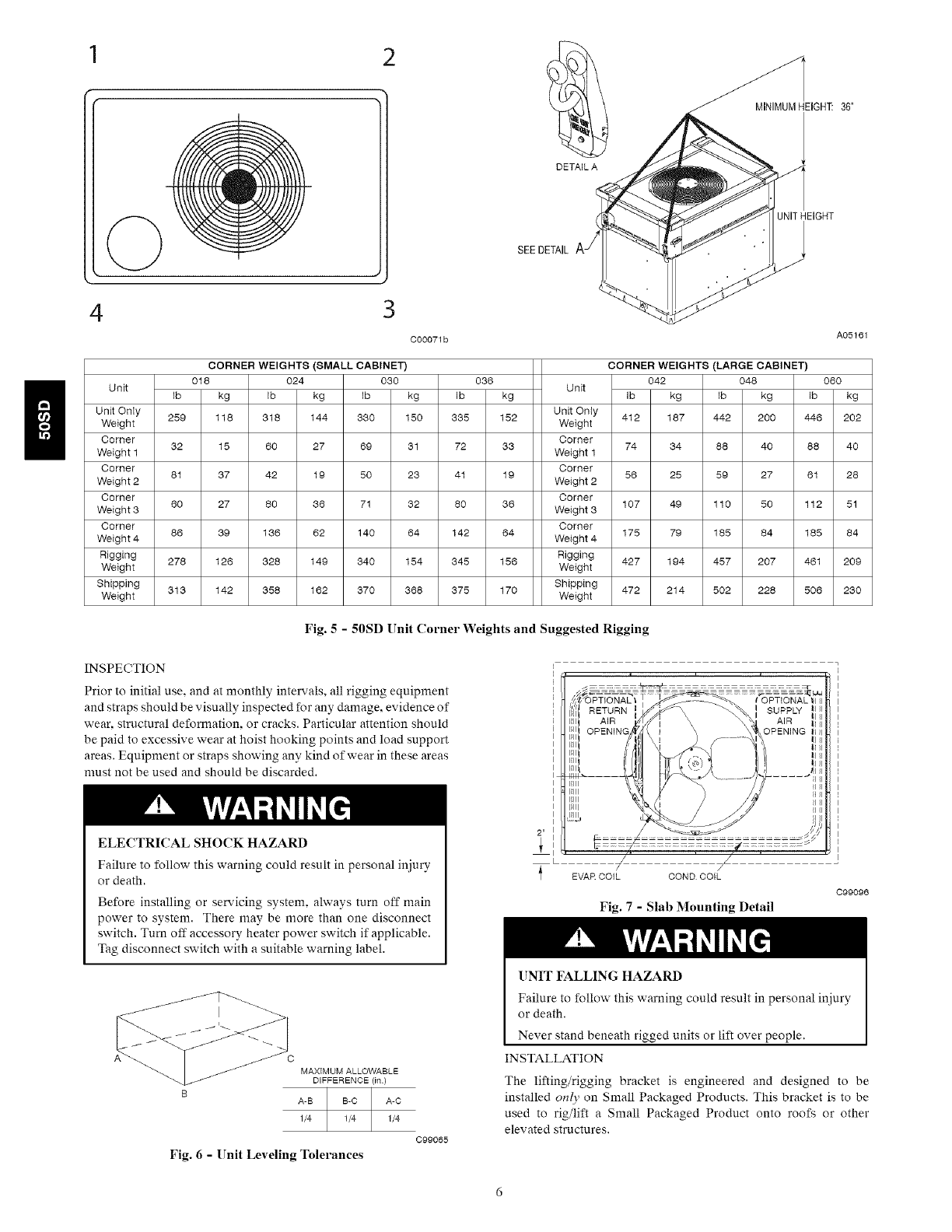
DETAIL A
SEE DETAIL Aj
MINIMUMHEIGHT: 36'
UNITHEIGHT
/
A05161
Unit
Unit Only
Weight
Corner
Weight 1
Corner
Weight 2
Corner
Weight 3
Corner
Weight 4
Rigging
Weight
Shipping
Weight
CORNER WEIGHTS (LARGE CABINET)
Unit
Unit Only
Weight
Corner
Weight 1
Corner
Weight 2
Corner
Weight 3
Corner
Weight 4
Rigging
Weight
Shipping
Weight
Fig. 5 - 50SD Unit Corner Weights and Suggested Rigging
INSPECTION
Prior to initial use. and at monthly intervals, all rigging equipment
and straps should be visually inspected for any damage, evidence of
wear, structural deformation, or cracks. Particular attention should
be paid to excessive wear at hoist hooking points and load support
areas. Equipment or straps showing any kind of wear in these areas
must not be used and should be discarded.
ELECTRICAL SHOCK HAZARD
Failure to follow this warning could result in personal injury
Drdeath.
Before installing or servicing system, always turn off main
power to system. There may be more than one disconnect
switch. Turn off accessory heater power switch if applicable.
Tag disconnect switch with a suitable warning label.
MAXIMUM ALLOWABLE
DIFFERENCE (in)
A-B A-O
1/4 1/4
Fig. 6 -Unit Leveling Tolerances
C99065
EVAR COIL COND COIL
Fig. 7 - Slab Mounting Detail
tOPTIONAL '41 II
}
}
}
}
}
}
C99096
[;NIT FALLING HAZARD
Failure to follow this warning could result in personal injury
or death.
Never stand beneath rigged units or lift over people.
INSTALLATION
The lifting/rigging bracket is engineered and designed to be
installed on(y on Small Packaged Products. This bracket is to be
used to rig/lift aSmall Packaged Product onto roofs or other
elevated structures.
PROPERTYDAMAGEHAZARD
Failureto followthiswarningcouldresultinpersonal
injury/deathorpropertydamage.
Riggingbracketsforoneunituseonly.Whenremovinga
unitattheendofitsusefullife,useanewsetofbrackets.
USEOFRIGGINGBRACKET
Field Installation of Ri_gin_ Bracket
1. If applicable, remove unit from shipping carton. Leave top
shipping skid on the unit for use as a spreader bar to prevent
the rigging straps from damaging the unit. If the skid is not
available, use a spreader bar of sufficient length to protect the
unit from damage.
2. Remove 4 screws in unit corner posts.
3. Attach each of the 4 metal rigging brackets under the panel
rain lip (See Fig. 5). Use the screws removed in step 2 above
to secure the brackets to the unit.
PROPERTY DAMAGE HAZARD
Failure to follow this warning could result in personal
injury/death or property damage.
Rigging bracket MUST be under the rain lip to provide
adequate lifting.
PROPERTY DAMAGE HAZARD
Failure to follow this warning could result in personal
injury/death or property damage.
Do not strip screws when re-securing the unit. If a screw is
stripped, replace the stripped one with a larger diameter screw
(included).
Ri_,ing/Liftin_, of Unit
1. Bend top of brackets down approximately 30 degrees from
the corner posts.
2. Attach straps of equal length to the rigging brackets at
opposite ends of the unit. Be sure straps are rated to hold the
weight of the unit (See Fig. 5).
3. Attach a clevis of sufficient strength in the middle of the
straps. Adjust the clevis location to ensure unit is lifted level
with the ground.
4. After unit is securely in place detach rigging straps. Remove
corner posts screws, and rigging brackets then reinstall
screws.
UNIT FALLING HAZARD
Failure to follow this warning could result in personal
injury/death or property damage.
When straps are taut. the clevis should be a minimum of 36 in.
(914 mm) above the unit top cover.
After the unit is placed on the roof curb or mounting pad, remove
the top crating.
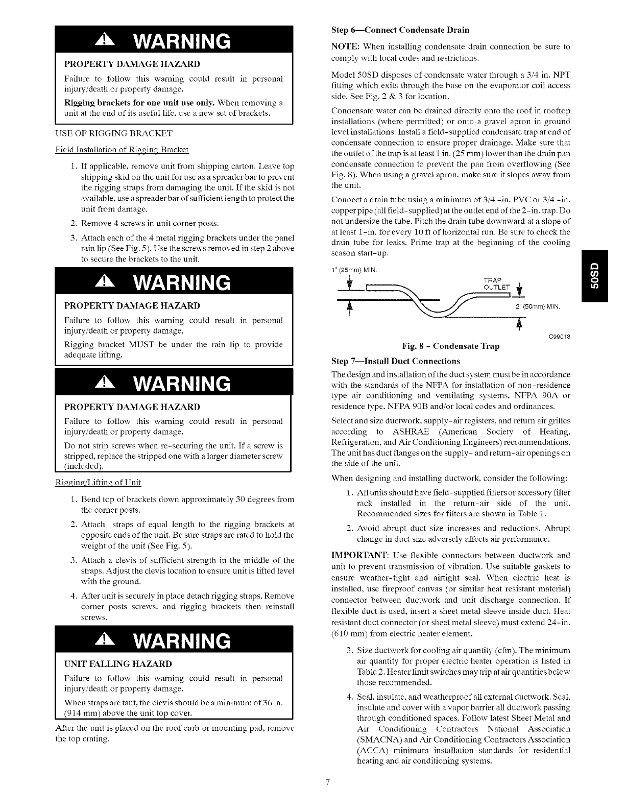
Step 6--Connect Condensate Drain
NOTE: When installing condensate drain connection be sure to
comply with local codes and restrictions.
Model 50SD disposes of condensate water through a 3/4 in. NPT
fitting which exits through the base on the evaporator coil access
side. See Fig. 2 & 3 for location.
Condensate water can be drained directly onto the roof in rooftop
installations (where permitted) or onto a gravel apron in ground
level installations. Install a field-supplied condensate trap at end of
condensate connection to ensure proper drainage. Make sure that
the outlet of the trap is at least 1 in. (25 mm) lower than the drain pan
condensate connection to prevent the pan from overflowing (See
Fig. 8). When using a gravel apron, make sure it slopes away from
the unit.
Connect a drain tube using a minimum of 3/4 -in. PVC or 3/4 -in.
copper pipe (all field-supplied) at the outlet end of the 2-in. trap. Do
not undersize the tube. Pitch the drain tube downward at a slope of
at least 1-in. for every 10 ft of horizontal run. Be sure to check the
drain tube for leaks. Prime trap at the beginning of the cooling
season start-up.
1" (25ram) MIN.
TRAP
2" (50mm) MIN.
099013
Fig. 8 - Condensate Trap
Step 7--Install Duct Connections
The design and installation of the duct system must be in accordance
with the standards of the NFPA for installation of non-residence
type air conditioning and ventilating systems, NFPA 90A or
residence type, NFPA 90B and/or local codes and ordinances.
Select and size ductwork, supply- air registers, and return air grilles
according to ASHRAE (American Society of Heating,
Refrigeration, and Air Conditioning Engineers) recommendations.
The unit has duct flanges on the supply- and return-air openings on
the side of the unit.
When designing and installing ductwork, consider the following:
1. All units should have field- supplied filters or accessory filter
rack installed in the return-air side of the unit.
Recommended sizes for filters are shown in Table 1.
2. Avoid abrupt duct size increases and reductions. Abrupt
change in duct size adversely affects air performance.
IMPORTANT: Use flexible connectors between ductwork and
unit to prevent transmission of vibration. Use suitable gaskets to
ensure weather-tight and airtight seal. When electric heat is
installed, use fireproof canvas (or similar heat resistant material)
connector between ductwork and unit discharge connection. If
flexible duct is used. insert a sheet metal sleeve inside duct. Heat
resistant duct connector (or sheet metal sleeve) must extend 24-in.
(610 mm) from electric heater element.
3. Size ductwork for cooling air quantity (cfm). The minimum
air quantity for proper electric heater operation is listed in
Table 2. Heater limit switches may trip at air quantities below
those recommended.
4. Seal. insulate, and weatherproof all external ductwork. Seal,
insulate and cover with a vapor barrier all ductwork passing
through conditioned spaces. Follow latest Sheet Metal and
Air Conditioning Contractors National Association
(SMACNA) and Air Conditioning Contractors Association
(ACCA) minimum installation standards for residential
heating and air conditioning systems.
n
5. Secure all ducts to building structure. Flash, weatherproof,
and vibration-isolate duct openings in wall or roof
according to good construction practices.
CONFIGURING UNITS FOR DOWNFLOW (VERTICAL)
DISCHARGE
ELECTRICAL SHOCK HAZARD
Failure to follow this warning could result in personal injury
or death.
Before performing service or maintenance operations on the
system, turn off main power to unit and install lockout tag.
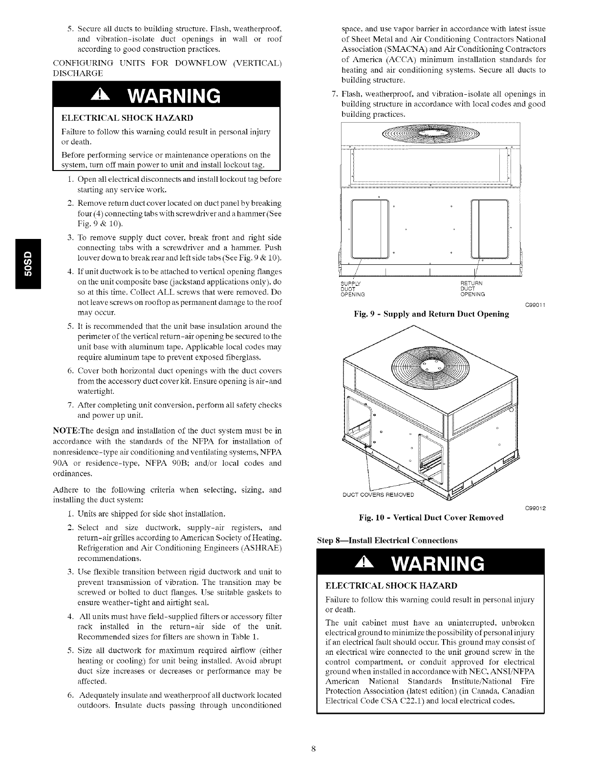
1. Open all electrical disconnects and install lockout tag before
starting any service work.
2. Removereturnductcover locatedon ductpanelbybreaking
four (4) connecting tabs with screwdriver and a hammer (See
Fig. 9 & 10).
3. To remove supply duct cover, break front and right side
connecting tabs with a screwdriver and a hammer. Push
louver down to break rear and left side tabs (See Fig. 9 & 10).
4. If unit ductwork is to be attached to vertical opening flanges
on the unit composite base (jackstand applications only), do
so at this time. Collect ALL screws that were removed. Do
not leave screws on rooftop as permanent damage to the roof
may occur.
5. It is recommended that the unit base insulation around the
perimeter of the vertical return-air opening be secured to the
unit base with aluminum tape. Applicable local codes may
require aluminum tape to prevent exposed fiberglass.
6. Cover both horizontal duct openings with the duct covers
from the accessory duct cover kit. Ensure opening is air-and
watertight.
7. After completing unit conversion, perform all safety checks
and power up unit.
NOTE:The design and installation of the duct system must be in
accordance with the standards of the NFPA for installation of
nonresidence-type air conditioning and ventilating systems. NFPA
90A or residence-type, NFPA 90B; and/or local codes and
ordinances.
Adhere to the following criteria when selecting, sizing, and
installing the duct system:
1. Units are shipped for side shot installation.
2. Select and size ductwork, supply-air registers, and
return-air grilles according to American Society of Heating,
Refrigeration and Air Conditioning Engineers (ASHRAE)
recommendations.
3. Use flexible transition between rigid ductwork and unit to
prevent transmission of vibration. The transition may be
screwed or bolted to duct flanges. Use suitable gaskets to
ensure weather-tight and airtight seal.
4. All units must have field-supplied filters or accessory filter
rack installed in the return-air side of the unit.
Recommended sizes for filters are shown in Table 1.
5. Size all ductwork for maximum required airflow (either
heating or cooling) for unit being installed. Avoid abrupt
duct size increases or decreases or performance may be
affected.
6. Adequately insulate and weatherproof all ductwork located
outdoors. Insulate ducts passing through unconditioned
space, and use vapor barrier in accordance with latest issue
of Sheet Metal and Air Conditioning Contractors National
Association (SMACNA) and Air Conditioning Contractors
of America (ACCA) minimum installation standards for
heating and air conditioning systems. Secure all ducts to
building structure.
Flash, weatherproof, and vibration-isolate all openings in
building structure in accordance with local codes and good
building practices.
SUPP_ RETURN
DUCT DUCT
OPENING OPEN{NG
Fig. 9- Supply and Return Duct Opening
C99011
DUCT COVERS REMOVED
Fig. 10 - Vertical Duct Cover Removed
Step 8---Install Electrical Connections
C99012
ELECTRICAL SHOCK HAZARD
Failure to follow this warning could result in personal injury
or death.
The unit cabinet must have an uninterrupted, unbroken
electrical ground to minimize the possibility of personal injury
if an electrical fault should occur. This ground may consist of
an electrical wire connected to the unit ground screw in the
control compartment, or conduit approved for electrical
ground when installed in accordance with NEC, ANSI/NFPA
American National Standards Institute/National Fire
Protection Association (latest edition) (in Canada, Canadian
Electrical Code CSA C22.1) and local electrical codes.
UNITCOMPONENTDAMAGEHAZARD
Failuretofollowthiscautionmayresultindamagetotheunit
beinginstalled.
1.MakeallelectricalconnectionsinaccordancewithNEC
ANSI/NFPA(latestedition)andlocalelectricalcodes
governingsuchwiring.In Canada,all electrical
connectionsmustbeinaccordancewithCSAstandard
C22.1CanadianElectricalCodePart1andapplicablelocal
codes.Refertounitwiringdiagram.
2.Useonlycopperconductorforconnectionsbetween
field-suppliedelectricaldisconnectswitchandunit.DO
NOTUSEALUMINUMWIRE.
3.Besurethathigh-voltagepowertounitiswithinoperating
voltagerangeindicatedonunitratingplate.On3-phase
units,ensurephasesarebalancedwithin2percent.Consult
localpowercompanyforcorrectionofimpropervoltage
and/orphaseimbalance.
4.Donotdamageinternalcomponentswhendrillingthrough
anypaneltomountelectricalhardware,conduit,etc.
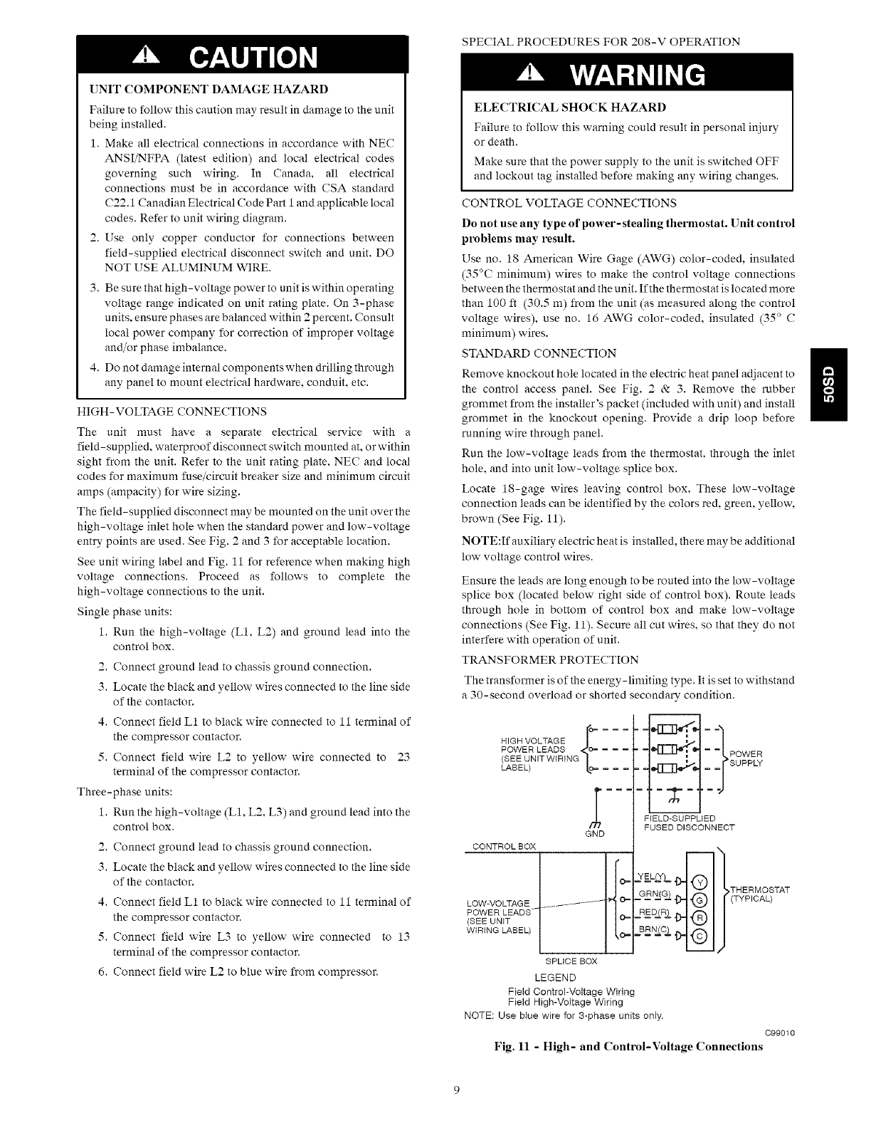
HIGH-VOLTAGECONNECTIONS
Theunitmusthavea separateelectricalservicewitha
field-supplied,waterproofdisconnectswitchmountedat,orwithin
sightfromtheunit.Refertotheunitratingplate.NECandlocal
codesformaximumfuse/circuitbreakersizeandminimumcircuit
amps(ampacity)forwiresizing.
Thefield-supplieddiscnnnectmaybemountedontheunitoverthe
high-voltageinletholewhenthestandardpowerandlow-voltage
entrypointsareused.SeeFig.2and3foracceptablelocation.
SeeunitwiringlabelandFig.11forreferencewhenmakinghigh
voltageconnections.Proceedasfollowsto completethe
high-voltageconnectionstotheunit.
Singlephaseunits:
1.Runthehigh-voltage(L1,L2)andgroundleadintothe
controlbox.
2.Connectgroundleadtochassisgroundconnection.
3.Locatetheblackandyellowwiresconnectedtothelineside
ofthecontactor.
4.ConnectfieldL1toblackwireconnectedto11terminalof
thecompressorcontactor.
5.ConnectfieldwireL2toyellowwireconnectedto 23
terminalofthecompressorcontactor.
Three-phaseunits:
1.Runthehigh-voltage(L1,L2,L3)andgroundleadintothe
controlbox.
2.Connectgroundleadtochassisgroundconnection.
3.Locatetheblackandyellowwiresconnectedtothelineside
ofthecontactor.
4.ConnectfieldL1toblackwireconnectedto11terminalof
thecompressorcontactor.
5.ConnectfieldwireL3toyellowwireconnectedto13
terminalofthecompressorcontactor.
6.ConnectfieldwireL2tobluewirefromcompressor.
SPECIALPROCEDURESFOR208-VOPERATION
ELECTRICALSHOCKHAZARD
Failuretofollowthiswarningcouldresultinpersonalinjury
ordeath.
MakesurethatthepowersupplytotheunitisswitchedOFF
andlockouttaginstalledbeforemakinganywiringchanges.
CONTROLVOLTAGECONNECTIONS
Donotuseanytype of power-stealing thermostat. Unit control
problems may result.
Use no. 18 American Wire Gage (AWG) color-coded, insulated
(35°C minimum) wires to make the control voltage connections
between the thermostat and the unit. If the thermostat is located more
than 100 ft (30.5 m) from the unit (as measured along the control
voltage wires), use no. 16 AWG color-coded, insulated (35 ° C
minimum) wires.
STANDARD CONNECTION
Remove knockout hole located in the electric heat panel adjacent to
the control access panel. See Fig. 2 &: 3. Remove the rubber
grommet from the installer's packet (included with unit) and install
grommet in the knockout opening. Provide a drip loop before
running wire through panel.
Run the low-voltage leads from the thermostat, through the inlet
hole. and into unit low-voltage splice box.
Locate 18-gage wires leaving control box. These low-voltage
connection leads can be identified by the cnlors red, green, yellow,
brown (See Fig. 11).
NOTE:If auxiliary electric heat is installed, there may be additional
low voltage control wires.
Ensure the leads are long enough to be routed into the low-voltage
splice box (located below right side of control box). Route leads
through hole in bottom of control box and make low-voltage
connections (See Fig. 11). Secure all cut wires, so that they do not
interfere with operation of unit.
TRANSFORMER PROTECTION
The transformer is of the energy-limiting type. It is set to withstand
a 30-secnnd overload or shorted secondary condition.
HIGH VOLTAGE r --- -
POWER LEADS lc e,- ----
(SEE UNIT WIRING
LABEL) _ ---
CONTROLBOX
LOW-VOLTAGE
POWER LEADS _-
(SEE UNIT
WIRING LABEL)
SPLICE BOX
LEGEND
FIELD-SUPPLIED
FUSED DISCONNECT
l i (THYEIRCNA° TAT
® I/
Field Control-Voltage Wiring
Field High-Voltage Wiring
NOTE: Use blue wire for 3-phase units only,
099010
Fig. 11 - High- and Control-Voltage Connections
n
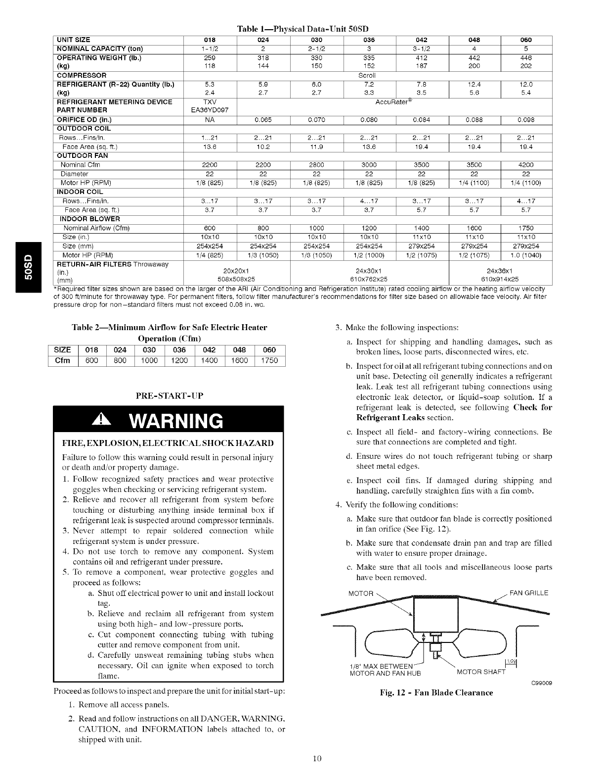
Table
018 024
1-1/2 2
259 318
118 144
1--Physical Data=Unit 50SD
030 036
2-1/2 3
330 335
150
UNIT SIZE 042 048 060
NO MINAL CAPACITY (ton) 3 - 1/2 4 5
OPERATING WEIGHT (Ib,) 412 442 446
(kg) 152 187 200 202
COMPRESSOR Scroll
REFRIGERANT (R-22) Quantity (Ib,) 5.3 5.9 6.0 7.2 7.8 12.4 12.0
(kg) 2.4 2.7 2.7 3.3 3,5 5,6 5.4
REFRIGERANT METERING DEVICE TXV AccuRater '_
PART NUMBER EA35YD097
ORIFICE OD (in.) NA 0.065 0.070 0.080 0.084 0.088 0.099
OUTDOOR COIL
Rows...Fins/in. 1 ,,.21 2...21 2...21 2...21 2...21 2...21 2...21
Face Area (sq. ft.) 13,5 10.2 11.9 13.5 19.4 19.4 19,4
OUTDOOR FAN
Nominal Ofm 2200 2200 2800 3000 3500 3500 4200
Diameter 22 22 22 22 22 22 22
Motor HP (RPM) 1/8 (825) 1/8 (825) 1/8 (825) 1/8 (825) 1/8 (825) 1/4 (1100) 1/4 (1100)
INDOOR COIL
Rows...Fins/in. 3,,.17 3...17 3...17 4...17 3...17 3...17 4...17
Face Area (sq. ft.) 3.7 3,7 3.7 3.7 5,7 5,7 5.7
INDOOR BLOWER
Nominal Airflow (Ofm) 600 800 10OO 1200 1400 1600 1750
Size (in,) 10x10 10x10 10x10 10x10 11x10 11x10 11x10
Size (mm) 254x254 254x254 254x254 254x254 279x254 279x254 279x254
Motor HP (RPM) 1/4 (825) 1/3 (1050) 1/3 (1050) 1/2 (1000) 1/2 (1075) 1/2 (1075) 1,0 (1040)
RETURN-AIR FILTERS Throwaway
(in.) 20x20x1 24x30x1 24x36x1
(mm) 508x508x25 610x762x25 610x914x25
*Required filter sizes shown are based on the larger of the ARI (Air Conditioning and Refrigeration institute) rated cooling airflow or the heating airflow velocity
of 300 ft/mlnute for throwaway type. For permanent filters, f@low filter manufacturer's recommendations for filter size based on allowable face velocity. Air filter
pressure drop for non-standard filters must not exceed 0.08 in. wc.
Table 2--Minimum Airflow for Safe Electric Heater
Operation (Cfm)
s,zE 018 o2410301o361o421o 81o6oI
Cfm 600 800 1000 1200 1400 1600 1750
PRE- START- UP
FIRE, EXPLOSION, ELECTRICAL SHOCK HAZARD
Failure to follow this warning could result in personal injury
or death and/or property damage.
1. Follow recognized safety practices and wear protective
goggles when checking or servicing refrigerant system.
2. Relieve and recover all refrigerant from system before
touching or disturbing anything inside terminal box if
refrigerant leak is suspected around compressor terminals.
3. Never attempt to repair soldered connection while
refrigerant system is under pressure.
4. Do not use torch to remove any component. System
contains oil and refrigerant under pressure.
5. To remove a component, wear protective goggles and
proceed as follows:
a. Shut off electrical power to unit and install lockout
tag.
b. Relieve and reclaim all refrigerant from system
using both high- and low-pressure ports.
c. Cut component connecting tubing with tubing
cutter and remove component from unit.
d. Carefully unsweat remaining tubing stubs when
necessary. Oil can ignite when exposed to torch
flame.
Proceed as follows to inspect and prepare the unit for initial start- up:
1. Remove all access panels.
2. Read and follow instructions on all DANGER, WARNING.
CAUTION. and INFORMATION labels attached to, or
shipped with unit.
3. Make the following inspections:
a. Inspect for shipping and handling damages, such as
broken lines, loose parts, disconnected wires, etc.
b. Inspect for oil at all refrigerant tubing connections and on
unit base. Detecting oil generally indicates a refrigerant
leak. Leak test all refrigerant tubing connections using
electronic leak detector, or liquid-soap solution. If a
refrigerant leak is detected, see following Check for
Refrigerant Leaks section.
c. Inspect all field- and factory-wiring connections. Be
sure that connections are completed and tight.
d. Ensure wires do not touch refrigerant tubing or sharp
sheet metal edges.
e. Inspect coil fins. If damaged during shipping and
handling, carefully straighten fins with a fin comb.
4. Verify the following conditions:
a. Make sure that outdoor fan blade is correctly positioned
in fan orifice (See Fig. 12).
b. Make sure that condensate drain pan and trap are filled
with water to ensure proper drainage.
c. Make sure that all tools and miscellaneous loose parts
have been removed.
MOTOR //FAN GRILLE
7
1/8" MAX BETWEEN
MOTOR AND FAN HUB MOTOR SHAFT
Fig. 12 - Fan Blade Clearance
C99009
10
START-UP
CHECK FOR REFRIGERANT LEAKS
Proceed as follows to locate and repair a refrigerant leak and to
charge the unit:
1. Locate leak and make sure that refrigerant system pressure
has been relieved and reclaimed from both high- and
low-pressure ports.
2. Repair leak following accepted practices.
NOTE: Install a filter drier whenever the system has been opened
for repair.
3. Add a small charge of R-22 refrigerant vapor to system and
leak-test unit.
4. Recnver refrigerant from system and evacuate to 500
microns if no additional leaks are found.
5. Charge unit with R-22 refrigerant, using a volumetric
charging cylinder or accurate scale. Refer to unit rating plate
for required charge. Be sure to add extra refrigerant to
compensate for internal volume of filter drier.
START-UP AND MAKING ADJUSTMENTS
Complete the required procedures given in the Pre-Start-Up
section before starting the unit. Do not jumper any safety devices
when operating the unit. Do not operate the unit when the outdoor
temperature is below 40°F (4°C) (unless accessory low-ambient kit
is installed). Do not rapid cycle the compressor. Allow 5 minutes
between "on" cycles to prevent compressor damage.
CHECKING COOLING CONTROL OPERATION
Start and check the unit for proper cooling cnntrol operation as
follows:
1. Place room thermostat SYSTEM switch in OFF position.
Observe that blower motor starts when FAN switch is placed
in ON position and shuts down after 30 second fan time
delay expires when FAN switch is placed in AUTO position.
2. Place SYSTEM switch in COOL position and FAN switch
in AUTO position. Set cooling control below room
temperature. Observe that compressor, condenser fan, and
evaporator blower motors start. Observe that compressor
and outdoor fan shut down when control setting is satisfied
and that indoor blower shuts down after 30 second fan time
delay expires.
IMPORTANT: Three-phase, scroll compressors are direction
oriented. Unit must be checked to ensure proper compressor
3-phase power lead orientation. If not corrected within 5 minutes,
the internal protector will shut off the compressor. The 3-phase
power leads to the unit must be reversed to correct rotation. When
turning backwards, the difference between compressor suction and
discharge pressures may be dramatically lower than normal.
CHECKING AND ADJUSTING REFRIGERANT CHARGE
The refrigerant system is fully charged with R-22 refrigerant and
is tested and factory sealed.
NOTE: Adjustment of the refrigerant charge is not required unless
the unit is suspected of not having the proper R-22 charge.
A refrigerant charging label is attached to the outside of the service
access panel.
The charging label and tables shown refer to system temperatures
and pressures in cooling mode only.
NOTE: Allow system to operate for a minimum of 10 minutes
before checking or adjusting refrigerant charge.
IMPORTANT: When evaluating the refrigerant charge, an
indicated adjustment to the specified factory charge must always be
very minimal. If a substantial adjustment is indicated, an abnormal
condition exists somewhere in the cooling system, such as
insufficient airflow across either coil or both coils.
018 Model Only
The charging chart (see Table 5) includes the required liquid line
temperature at given discharge line pressures and outdoor ambient
temperatures.
An accurate subcooling thermocouple or thermistor-type
thermometer and a gauge manifold are required when using the
subcooling charging method for evaluating the unit charge. Do not
use mercury or small dial-type thermometers because they are not
adequate for this type of measurement.
Proceed as follows:
1. Remove caps from low- and high-pressure service fittings.
2. Using hoses with valve core depressors, attach low- and
high-pressure gauge hoses to low- and high-pressure
service fittings, respectively.
3. Start unit in Cooling Mode and let unit run until system
pressures stabilize.
4. Measure and record the following:
a. Outdoor ambient-air temperature (°F (°C) db).
b. Liquid line temperature (°F (°C).
c. Discharge (high-side) pressure (psig).
5. Using "Cooling Charging Charts," compare outdoor-air
temperature (°F (°C) db) with the discharge line pressure
(psig) to determine desired system operating liquid line
temperature (see Table 5).
6. Compare actual liquid line temperature with desired liquid
line temperature. Using a tolerance of -+2°F (+/- 1.1°C), add
refrigerant if actual temperature is more than 2°F (1.1°C)
higher than proper liquid line temperature, or remove
refrigerant if actual temperature is more than 2°F (1.1°C)
lower than required liquid line temperature.
NOTE: If the problem causing the inaccurate readings is a
refrigerant leak, refer to the Check for Refrigerant Leaks section.
024 through 060 Models
The charging chart (see Table 5A) includes the required suction line
temperature at given suction line pressures and outdoor ambient
temperatures.
An accurate superheat thermocouple or thermistor-type
thermometer and a gauge manifold are required when using the
superheat charging method for evaluating the unit charge. Do not
use mercury or small dial-type thermometers because they are not
adequate for this type of measurement.
Proceed as follows:
1. Remove caps from low- and high-pressure service fittings.
2. Using hoses with valve core depressors, attach low- and
high-pressure gauge hoses to low- and high-pressure
service fittings, respectively.
3. Start unit and let run until system pressures stabilize.
4. Measure and record the following:
a. Outdoor ambient-air temperature (°F (°C) db).
b. Suction-tube temperature (°F (°C)) at low-side service
fitting.
c. Suction (low-side) pressure (psig).
11
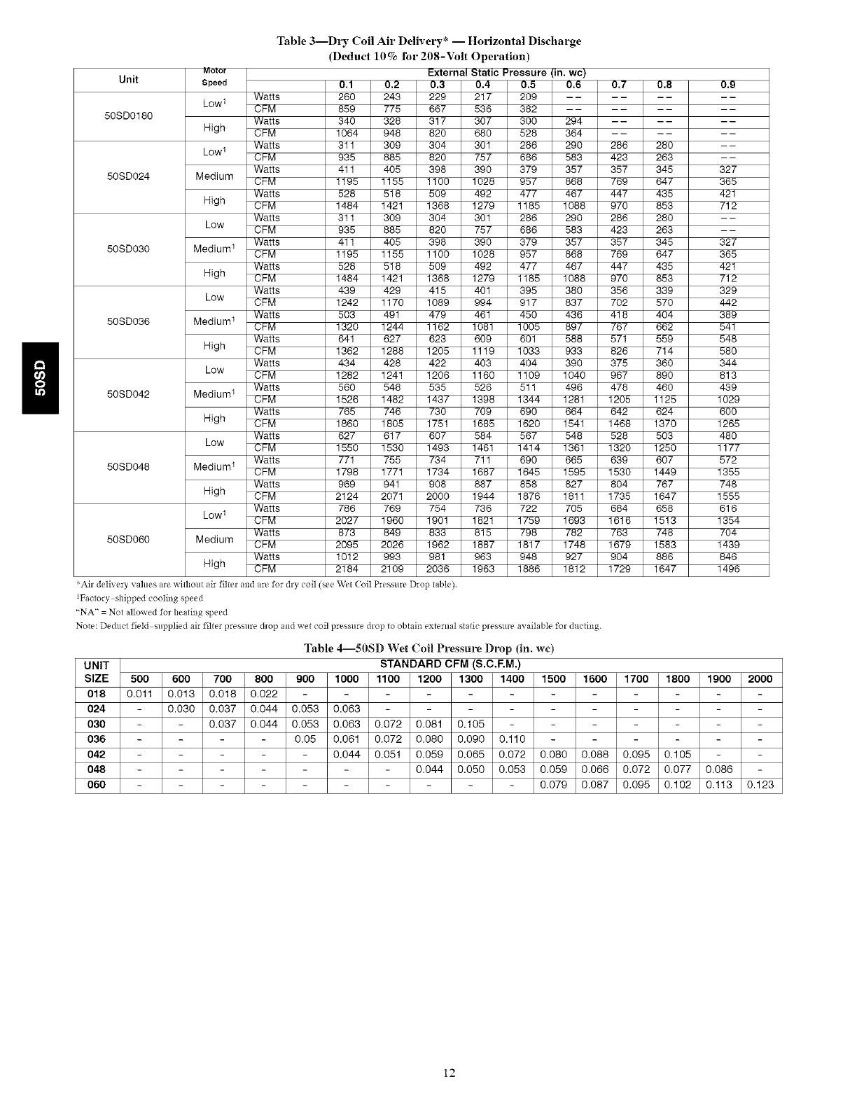
Table3--Dry Coil Air Delivery* -- Horizontal Discharge
(Deduct 10% for 208-Volt Operation)
External Static Pressure (in. wc)
Unit
50SD0180
50SD024
50SD030
50SD036
50SD042
50SD048
50SD060
Molor
Speed
Low 1
High
Low 1
Medium
High
Low
Medium 1
High
Low
Medium 1
High
Low
Medium 1
High
Low
Medium 1
High
Low 1
Medium
Watts
CFM
Watts
CFM
Watts
CFM
Watts
CFM
Watts
CFM
Watts
CFM
Watts
CFM
Watts
CFM
Watts
CFM
Watts
CFM
Watts
CFM
Watts
CFM
Watts
CFM
Watts
CFM
Watts
CFM
Watts
0.1 0.2 0.3 0.4 0.5 0.6
260 243 229 217 209 - -
859 775 667 536 382 - -
340 326 317 307 300 294
1064 948 620 680 528 364
311 309 304 301 286 290
935 885 620 757 686 583
411 405 398 390 379 357
1195 1155 1100 1028 957 868
528 516 509 492 477 467
1484 1421 1368 1279 1185 1088
311 309 304 301 286 290
935 885 620 757 686 583
411 405 398 390 379 357
1195 1155 1100 1028 957 868
528 516 509 492 477 467
1484 1421 1368 1279 1185 1088
439 429 415 401 395 380
1242 1170 1089 994 917 837
503 491 479 461 450 436
1320 1244 1162 1081 1005 897
641 627 623 609 601 588
1362 1288 1205 1119 1033 933
434 426 422 403 404 390
1282 1241 1206 1160 1109 1040
560 548 535 526 511 496
1526 1482 1437 1398 1344 1281
765 746 730 709 690 664
1860 1805 1751 1685 1620 1541
627 617 607 584 567 548
1550 1530 1493 1461 1414 1361
771 755 734 711 690 665
0.7 0.8 0.9
286 280 - -
423 263 --
357 345 327
769 647 365
447 435 421
970 853 712
286 280 - -
423 263 --
357 345 327
769 647 365
447 435 421
970 853 712
356 339 329
702 570 442
418 404 389
767 662 541
571 559 548
626 714 580
375 360 344
967 890 613
478 460 439
1205 1125 1029
642 624 600
1468 1370 1265
528 503 480
1320 1250 1177
639 607 572
1355
748
1555
616
1354
704
1439
846
1496
CFM
Watts
CFM
Watts
CFM
Watts
CFM
Watts
High CFM
1796 1771 1734
969 941 908
2124 2071 2000
766 769 754
2027 1960 1901
673 849 633
2095 2026 1962
1012 993 981
2184 2109 2036
Air delivery values are without air filter and are for dry coil (see Wet Coil Pressure Drop table).
iFactory shipped cooling speed
"NA" = Not allowed for heating speed
1687 1645 1595 1530 1449
887 658 827 604 767
1944 1876 1811 1735 1647
736 722 705 684 656
1821 1759 1693 1616 1513
815 798 782 763 748
1887 1817 1748 1679 1583
963 948 927 904 886
1963 1886 1812 1729 1647
Note: Deduct field supplied air filter pressure drop and wet coil presalre drop to obtain external static pressure available for ducting.
Table 4--50SDWet Coil Pressul_ Drop (in. wc)
UNIT STANDARD CFM (S.C.EM.)
SIZE 500 600 700 800 900 1000 1100 1200 1300 1400 1500 1600 1700 1800 1900 2000
018 0.011 0.013 0.018 0.022 - -
024 0.030 0.037 0.044 0.053 0.063 - -
030 0.037 0.044 0.053 0.063 0.072 0.081 0.105 -
036 0.05 0.061 0.072 0.080 0.090 0.110 -
042 0,044 0.051 0,059 0.065 0,072 0.080 0,088 0.095 0,105 -
048 0.044 0.050 0.053 0.059 0.066 0.072 0.077 0.086
060 - 0.079 0.087 0.095 0.102 0.113 0.123
12
cc /_ i D
SCi E,IA i ¢
_K 2'd8,2 [ : ;,0
,], <
L}]1 '" c ii c,r E> LK :C::
EOUI? ONC l/, 'l l':: " CC'_ SSO IIUG
,' ........./%
i' ......._n .......... 2Z::
'ELi{E} _ CCMP
SCH_A_C m _ 4/I DL J
ON HEA'FE_ACCESSORY.;4Z _ r c i .... ! U )I
...... _" O} 0 J F_L 0/8
8i _
ii7 h/,I '
JJANI --Orl [ Cif, {{--
'SRN ' JI 'SRN ' [ I
/l;' i
d
i :
i YI °,1 :!
TH2
i i _ f
i i
i i
i i
J
i$8 bOTE 8
8OhMO[' [
....................CiiN........
: ..........................C7f'i............
1i5/ (5 KW,_ :-. /- \
/
P, K :-- "/_ISN
,t
R R F 'r'_ ' - _
x x__
l/ ",,f 5,.2._ .<oN_,_-_.,., '/r_]' ':
iii 5=, ....ccscol,,,,c=,,,...................
i,R N
I!
(" [f'_
/x FIELD CPL/CE C CONFACIOR
o fIRM{HAL IMARKEI)) gAP i CAP,ACIIOR, _AN
o YERMiNA{ (UNMAP'KED) _AR 2 CAPAC[_OR, COMP
o SRIIC_ C_P' S CAPACITOR, INDUCER
SPLICE {_AR_EDI {OMP COMPRESSOR MOTOR
P,_CIORY WiRiN_ ROUIP, EOU]PMENT
.... FIELD CONTROLWIRINg EU FUSE
GROUND
liIAIiR RELAY
WIP'[NO RTR HEATER
....... TO INDICATE COMMON {{M [NDOOR IAN _OrOR
POTENTIAL ONLY: OFM OUTDOORFAN MOTOP,
ROE I0 R[PR_SENI OT OUADRUPi_ TERMINA{
_iRiNG C_ StOW BlOW EUSE
TDR TIME DELAY P,ELAY
IH fliERMOSYAI IiEAIING
iRAN iiRANSI:OR_ER
NULL.
3
4
iF ANY OR iH ORIGINAL WR S FURNISHED ANY REPLACED,
71EY RISI B :sEPLACED W l '<PC 90 EO <" WRE
(R /IS OJ VAt I',{
II iFICE iAOFS IO1 IH _FYOS AT Aki 3UBiJASLS
SE 7b DO COPPE CONDUC ORS FOR FI D iNSTALLATION
FOR 'iilGI S r D" IFM, SCONkECI R D' OR 'BLUE < W !Y
/ROI,' /{)t 3 AN:) C()NN[C ]lie "BIK' WIN{
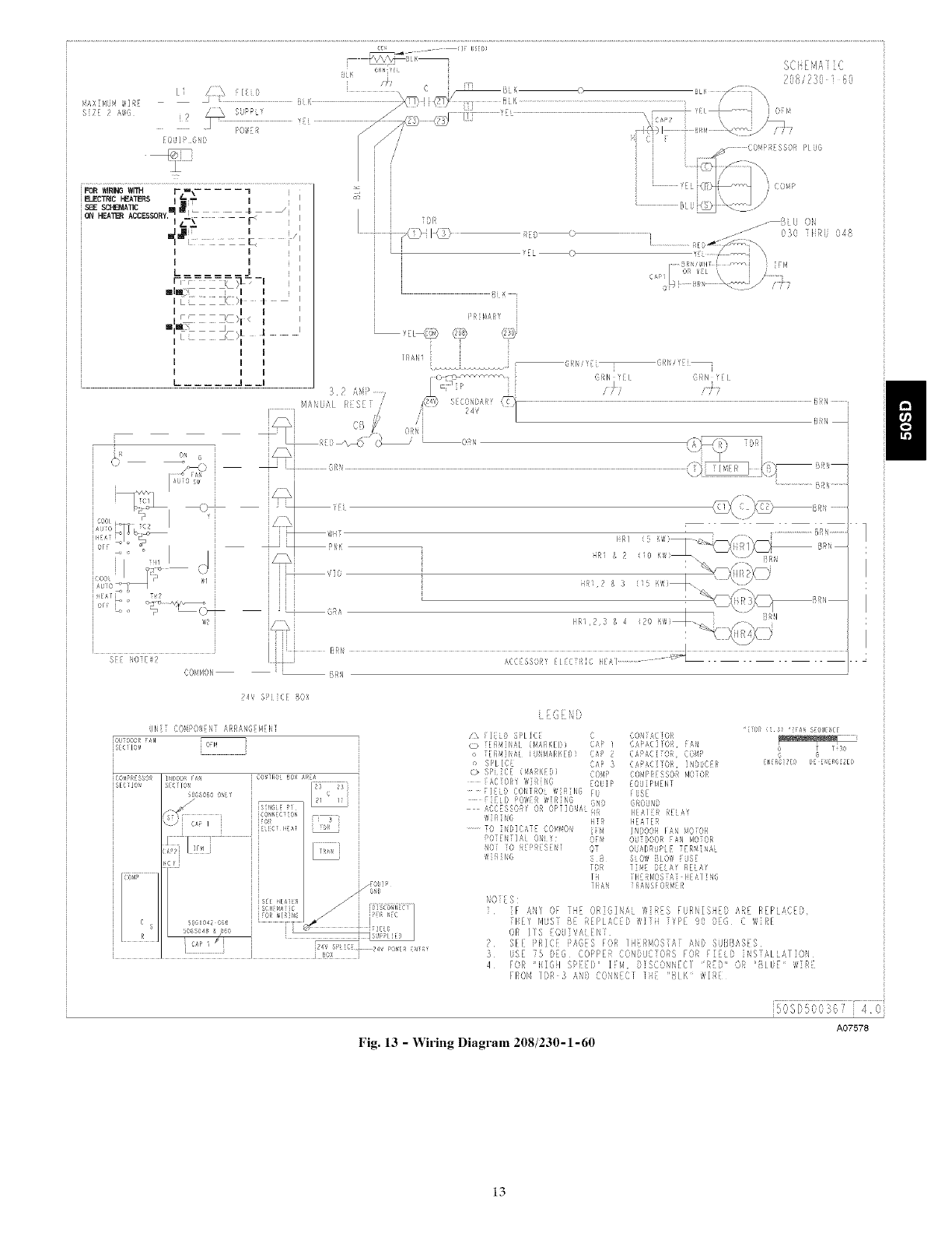
Fig. 13 -Wiring Diagram 208/230-1-60
.,JS[. _,,:_, 4 0
A07578
13
/
RAX tdW4 )_[R
S ;f 2 _g3 }/_ SLPP g
L2
/i
_OUTP BiB,
iFORWiRiNGWi_ F.=#" .... _
ELECTRICHEATERE '&=--,iT I I
i
SEE RCHEMA_C _: I
o°, =ERAO=EEEO",::
lii_ i I
SEE I_OTE#2
8t K i
qr F T7£
?08'730 } t_,
I I
irn r_r¢_p
i y ............ Pic:
'=1I _" (0 ;
b\ /
........................................................................................................................................................................_Lul_ _,t._./
]D
RE _> {
CAPii
?R14_t_!
r:;:'
i[ ZZ_ h T........
L J I 3 .4,
;............. qDNU/_L RES[ i!
f'Ni rOfI 'g[{I ]'S_,l,g I
--p°'qO'" ............. fEL iN g L
_/,_) E{or.,A,. {?i
s ?4
BRN
Oil
_ulo s_ ; ; BR'
--:,-: J : g _{ui_c _,-- ,
' z:::s .........."'..........
" _s I :: /'_l_ ,Fil _ R ( O )/£\. --\-.-/'_q'r/:\_
g F-I :;i,/\
> _Ci_ i/ ":RA Ib 3 & 4 " _77, i . _ /Br7
i ::1 : I
l Bm¢
C(}RIIOIi itIN f
24_ 5i1 £1 /]OX
JN[T COt4POfEb7 ARRAIOFR<'IY
¢O41' _[ SSDu
i S[,:l}O!
I/DOOR Ft*! CO4ilO 80)i I¢[A
s{cr ON
_S060 i 7} 1t
CN{
r '4 7 ........................
A?, , co _uu r_
Ji _" i {f: {
i ,<,_ i
i0g]
s s
SOil_4,_1re
ic _¢ 6
50_X04206 ......................
..........csf_ ,, !_ ..............
i. {. k.
Z% F ELD q_ /; C r_ TdrnR
_ [ER_]NDL {_4s,ii/,fO) CAP I C_PACITOR, ik, f(
o iljR_4/N_L _v_ (Y! _ CAP ?C_P;_{:i701i CORI¸>
o SPLICE CAP 5 CAPACiiOf_ iliDbC[{f_
¢:> SPLICE ,_A'_ED, C'3_ CO_PRESSORI,!OTO_
_OijZP EOUIPRENi
FACTC'Rg WlR]N6 Fb FUSE
.... r Fi D COfYROI ?dR]tO Grid 6ROd@
I]Elb POW[Fi WlFi/N'S HI tEAlEt !Ei£Y
...... DC /SSOFiI C'FiOPI ]ON_i 1ii7 IEA[ER
W]fT]f6 {If4 71D,cOp F_/I,i ,40701
.........fC' ]tl)] kfi] CC,!<'bON OU OtJ =OO_ fAN I,IOiOii
POTENTIAL 0 ) O] OIjDI)I¢IJl[I7 11 _"/NA
'7q S B SlOg BLOT7 rUSt
1'Oi IC' / +_1
WIIHI'dC, TO i{14E DELR' RELAI
' il f ili i71407,A[ i[1A i N(;
iRAf4 i RDI'iSFORVER
=]Ii)I i_ 31 "[FI_ SFOUENC[
i¢so
n
NOIES:
1 if ANY O_ iH c ORIGINAL WIRES FURNISHED ARE REPLACED,
THEY _UST B: REPLACED W]iH TYPE 90 tro G WiRE
OR IiS EOU]VALENT
2 SEE PR[CF PAGES FOR IIfERMOSIA] AND SUBBASFS
3 uSE 75 OEO COPPER CON%CrOPS FOR FIELD I_S[ALiArION
4 FOR HIGH s_rED _ {r#, DISCONNFC[ 'i!Et" OF! 'BIU_' WIRP
FROH /DR 3 A_D CONNECI [HE 'B{_" WIRF
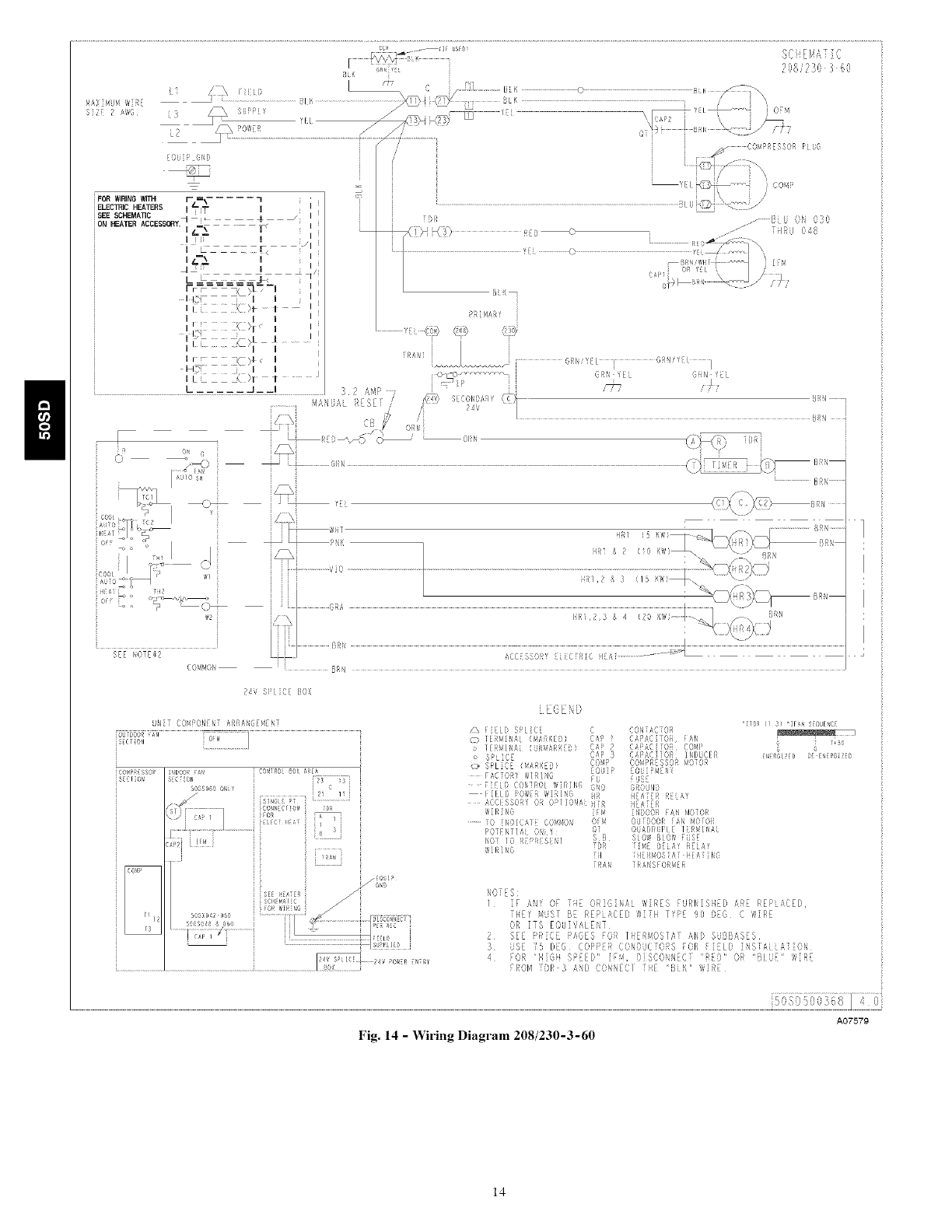
Fig. 14 -Wiring Diagram 208/230-3-60
A07579
14
:I _ i i I
I ;;I ," }l < I I
;12Z C ;_>t 4 .........
i i
IZZZ (>I < I
r i I
LI _d I
.................................................. - J3?A'_
,4ANUAi R] S] T
J
6i Y[[ GI'\
i i /-];i7 i _ ,
L
iR i
SEE _0(#2 I I ,
[}[Ri,i
24V S[[ it[ [OX
UN COM _,ONEt /_RR/q GEt, EN [
iou_Doo_FA_
iSFCT/@i
Si;C O_ I ]
5oGso_oo _
/,f 21
Ct,'4;[c (x
FOR
E C t_'
[
506_ 42 0_0
r.........................
24, SPL [ i 4d pO_,I! ,if
J_q ..............[
/J',
£_ F_ELt SPLICE C CONiACTOR
0 ]ERMiNAL (_AR_ED) CAP 1 CAPAC]]OR, FAN
o TEI_NiNAi (UN_AI_KED) CAP _ CAI_AC]{O_, CO_P
o SP[iC[ CAP 3 CAPACi[OR, i_DUCER
(_ SPLICE L_AR_FD) CO_i_ CO_PRESSO_ _OlOR
FACiORY WIRING EOSIP EOU_P_ENf
FiLLt COntROL _IRiNG [U FUSE
G_OUNO
_[ATER RFIAY
WIRING H_ H_ATER
iO iN_iCAIE CO,NON ][_ INDOOR FAN _0iOR
I_O]ENTiAi ONLY¸ OF_ OU]DOOii iA_ _0101_
NOT TO R_RESENT OT O(JAORLJPi[ _ER_INA[
_i_]NG SB SLOW BLOW FJSE
IDI_ [iN_ rELAY RELAY
ii[ iilEii_OSIAiiIEA[iNG
[RAN IIiA_SFOi_M_
4' [ S
2
3
[_GI/(_ DEE_ERGIZED
[ ANY OF FiiE OR]G[NA[ W ES FUPN SI D A:_E RFPLACED,
I Yy YUSJ BE REPL,'CED ,_/[ IYPE 90 DoG WIRE
OR IiS EOO]VA ELT
S F PRZCE PAGES OR iHERk*OSTA A!@ SURBASES
US t J) 6 COIP R CO I)UC Oi!S iOR i ] I D iLSi,H iA_l{}k
iOR i]GI Si]D IN, I IS(O',I!\ECJ "R [)" OR J! [' _, _[
FROM DR 3 AND {Y)'q,,EC Ii 5LK ,',IU
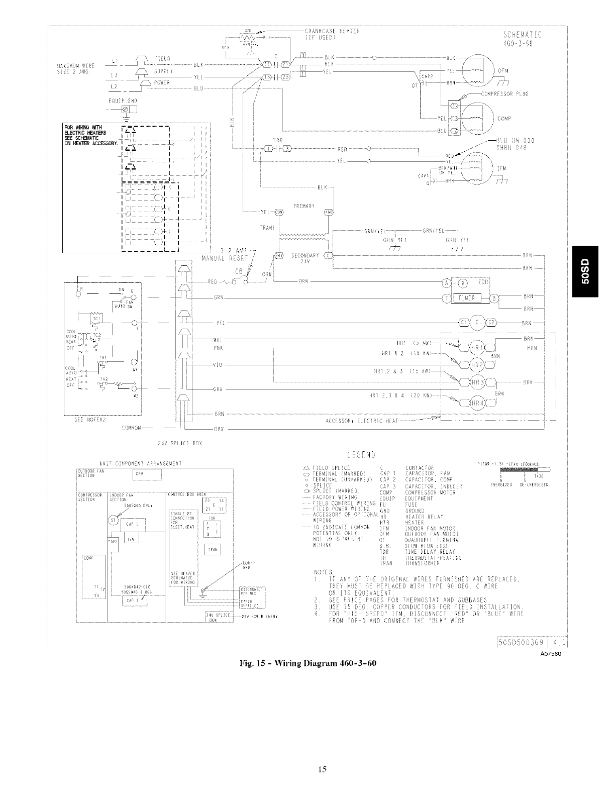
Fig. 15 -Wiring Diagram 460-3-60
50565C,0369i 40j
A07580
n
15
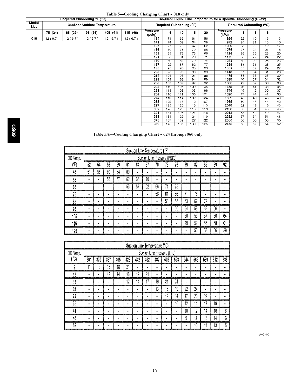
Table 5--Cooling Charging Chart - 018 only
Required Subcooling °F (°C) Required Liquid Line Temperature for aSpecific Subcooling (R-22)
.ode,, II
Size Outdoor Ambient Temperature Required Subcooling (°F) Required Subcooling (°C)
IPressureI 6 I lOI 16 I 2o11 Pressure
76 (24) 85 (29) 96 (36) 106 (41) 115 (46) (psig) I I I I I I (kPa) 368
018 12 6.7 12(6,7) 12(6.7) 12(6,7) 12(6.7) 134 I 71 I 88 I 61 I 56 II 924 22 19 16
141 I 74 I 6e I 54 I 5911 972 23 21 18
146 I 77 I 72 I 67 I 82111020 25 22 19
156 80 75 70 65 1076 27 24 21
163 I 83 I 78 I 73 I 68 II 1124 28 26 23
171100131173 I 7111 1179 30 27 24
179 89 84 79 74 1234 32 29 26
187 I 92 I 37 I 82 I 77 II 1269 33 31 23
1961°31901331301113613332 20
206 98 93 88 83 1413 37 34 31
214 I 101 I 98 I 91 I 38 II 1476 38 33 33
2231lO4199194139111536 40 37 34
233 107 102 97 92 1606 42 39 36
243 I 119 I 195 I 199 I 95 II 1676 43 41 38
25311131108110319811 174443 42 39
264 116 111 106 101 1620 47 44 41
274 I 119 I 114 I 109 I 104 II 1669 48 43 43
26511921117111211o711196530 47 44
297 125 120 115 110 2048 52 49 46
3o9 I 128 I 123 I 118 I 113 I I 2130 53 51 48
321,131,123,191,113,,221333 52 ,9
331 I I I III134129 124 119 2282 57 54 51
346 137 I 1321 127 I 12211 2386 58 56 53
359 140 135 130 125 2475 60 57 54
Table 5A--Cooling Charging Chart = 024 through 060 only
ODTemp.
(°F)
45
55
65
75
85
95
105
1t5
125
SuctionLineTem_
SuctionLinePressurePSL_
52 54 56 59 61 64 67 70 73 76 79 82 85 89 92
5t 55 60 64 69
53 57 62 66 70
53 57 62 66 71 75
56 61 66 71 76
53 58 63 67 72
50 54 58 62 66
50 53 57 60 64
49 52 55 58 6I
50 53 56 59
11
13
15
17
18
2O
22
23
25
27
28
3O
32
33
35
37
38
4O
42
43
45
47
48
50
52
ODTemp.
(oc)
7
t3
18
24
29
35
41
46
52
SuctionLineTem_
SuctionLinePres_
361 370 387 405 423 442 462 482 502 523 544 566 589 612 636
11 13 I5 18 21
I2 I4 16 19 21 _L_
___:__I2 14 17 19 21 24
13 I6 I9 22 24
12 14 17 20 22
10 12 t4 17 19
10 12 14 16 18
9 1t 13 14 16
t0 1t 13 15
A05109
ld
5. Using Cooling Charging Charts compare outdoor-air
temperature (°F (°C) db) with the suction line pressure
(psig) to determine desired system operating suction line
temperature (See Table 5A).
6. Compare actual suction-tube temperature with desired
suction-tube temperature. Using a tolerance of -+3°F
(-+1.7°C), add refrigerant if actual temperature is more than
3°F (1.7°C) higher than proper suction-tube temperature, or
remove refrigerant if actual temperature is more than 3°F
(1.7°C) lower than required suction-tube temperature.
NOTE: If the problem causing the inaccurate readings is a
refrigerant leak. refer to Check for Refrigerant Leaks section.
INDOOR AIRFLOW AND AIRFLOW ADJUSTMENTS
NOTE: For cooling operation, the recommended airflow is 350 to
450 cfm for each 12.000 Btuh of rated cooling capacity.
Table 3 shows cooling airflows at various external static pressures.
Refer to this table to determine the airflow for the system being
installed.
NOTE: Be sure that all supply- and return-air grilles are open, free
from obstructions, and adjusted properly.
ELECTRICAL SHOCK HAZARD
Failure to follow this warning could result in personal injury
or death.
Disconnect electrical power to the unit and install lockout tag
before changing blower speed.
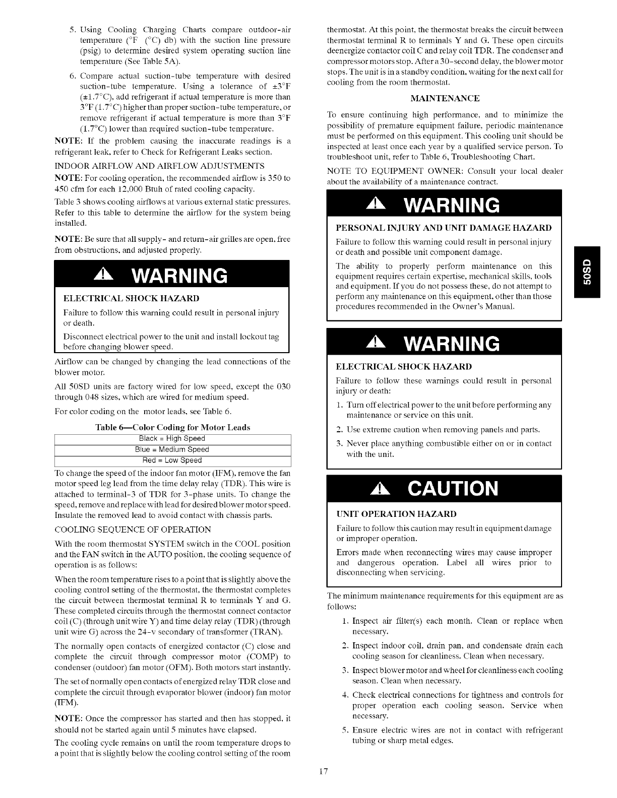
Airflow can be changed by changing the lead connections of the
blower motor.
All 50SD units are factory wired for low speed, except the 030
through 048 sizes, which are wired for medium speed.
For color coding on the motor leads, see Table 6.
Table 6--Color Coding for Motor Leads
Black = High Speed
Blue = Medium Speed
Red = Low Speed
To change the speed of the indoor fan motor (IFM), remove the fan
motor speed leg lead from the time delay relay (TDR). This wire is
attached to terminal-3 of TDR for 3-phase units. To change the
speed, remove and replace with lead for desired blower motor speed.
Insulate the removed lead to avoid contact with chassis parts.
COOLING SEQUENCE OF OPERATION
With the room thermostat SYSTEM switch in the COOL position
and the FAN switch in the AUTO position, the cooling sequence of
operation is as follov:s:
When the room temperature rises to a point that is slightly above the
cooling control setting of the thermostat, the thermostat completes
the circuit between thermostat terminal R to terminals Y and G.
These completed circuits through the thermostat connect contactor
coil (C) (through unit wire Y) and time delay relay (TDR) (through
unit wire G) across the 24-v secondary of transformer (TRAY).
The normally open contacts of energized contactor (C) close and
complete the circuit through compressor motor (COMP) to
condenser (outdoor) fan motor (OFM). Both motors start instantly.
The set of normally open contacts of energized relay TDR close and
complete the circuit through evaporator blower (indoor) fan motor
(IFM).
NOTE: Once the compressor has started and then has stopped, it
should not be started again until 5 minutes have elapsed.
The cooling cycle remains on until the room temperature drops to
a point that is slightly below the cooling control setting of the room
17
thermostat. At this point, the thermostat breaks the circuit between
thermostat terminal R to terminals Y and G. These open circuits
deenergize contactor coil C and relay coil TDR. The condenser and
compressor motors stop. After a 30-second delay, the blower motor
stops. The unit is in a standby condition, waiting for the next call for
cooling from the room thermostat.
MAINTENANCE
To ensure continuing high performance, and to minimize the
possibility of premature equipment failure, periodic maintenance
must be performed on this equipment. This cooling unit should be
inspected at least once each year by a qualified service person. To
troubleshoot unit, refer to Table 6, Troubleshooting Chart.
NOTE TO EQUIPMENT OWNER: Consult your local dealer
about the availability of a maintenance contract.
PERSONAL INJURY AND UNIT DAMAGE HAZARD
Failure to follow this warning could result in personal injury
or death and possible unit component damage.
The ability to properly perform maintenance on this
equipment requires certain expertise, mechanical skills, tools
and equipment. If you do not possess these, do not attempt to
perform any maintenance on this equipment, other than those
procedures recommended in the Owner's Manual.
ELECTRICAL SHOCK HAZARD
Failure to follow these warnings could result in personal
injury or death:
1. Turn off electrical power to the unit before performing any
maintenance or service on this unit.
2. Use extreme caution when removing panels and parts.
3. Never place anything combustible either on or in contact
with the unit.
UNIT OPERATION HAZARD
Failure to follow this caution may result in equipment damage
or improper operation.
Errors made when reconnecting wires may cause improper
and dangerous operation. Label all wires prior to
disconnecting when servicing.
The minimum maintenance requirements for this equipment are as
follows:
1. Inspect air filter(s) each month. (?lean or replace when
necessary.
2. Inspect indoor coil, drain pan, and condensate drain each
cooling season for cleanliness. Clean when necessary.
3. Inspect blov:er motor and wheel for cleanliness each cooling
season. Clean when necessary.
4. Check electrical connections for tightness and controls for
proper operation each cooling season. Service when
necessary.
5. Ensure electric wires are not in contact with refrigerant
tubing or sharp metal edges.
n
AIR FILTER
IMPORTANT: Never operate the unit without a suitable air filter
in the return- air duct system. Always replace the filter with the same
dimensional size and type as originally installed. See Table 1 for
recommended filter sizes.
Inspect air filter(s) at least once each month and replace
(throwaway-type) or clean (cleanable-type) at least twice during
each cooling season and twice during the heating season, or
whenever the filter becomes clogged with dust and lint.
INDOOR BLOWER AND MOTOR
NOTE: All motors are pre-lubricated. Do not attempt to lubricate
these motors.
For longer life, operating economy, and continuing efficiency, clean
accumulated dirt and grease from the blower wheel and motor
annually.
] ELECTRICAL SHOCK HAZARD
Failure to follow this warning could result in personal injury
or death.
Disconnect and tag electrical power to the unit before cleaning
and lubricating the blower motor and wheel.
To clean the blower motor and wheel:
1. Remove and disassemble blower assembly as follows:
a. Remove unit access panel.
b. Disconnect motor lead from time delay relay (TDR).
Disconnect yellow lead from terminal L2 of the contactor.
c. On all units remove blower assembly from unit. Remove
screws securing blower to blower partition and slide
assembly out. Be careful not to tear insulation in blower
compartment.
d. Ensure proper reassembly by marking blower wheel and
motor in relation to blower housing before disassembly.
e. Loosen setscrew(s) that secures wheel to motor shaft,
remove screws that secure motor mount brackets to
housing, and slide motor and motor mount out of
housing.
2. Remove and clean blower wheel as follows:
a. Ensure proper reassembly by marking wheel orientation.
b. Lift wheel from housing. When handling and/or cleaning
blower wheel, be sure not to disturb balance weights
(clips) on blower wheel vanes.
c. Remove caked-on dirt from wheel and housing with a
brush. Remove lint and/or dirt accumulations from wheel
and housing with vacuum cleaner, using soft brush
attachment. Remove grease and oil with mild solvent.
d. Reassemble wheel into housing.
e. Reassemble motor into housing. Be sure setscrews are
tightened on motor shaft flats and not on round part of
shaft.
f. Reinstall unit access panel.
3. Restore electrical power to unit. Start unit and check for
proper blower rotation and motor speeds during cooling
cycles.
OUTDOOR COIL, INDOOR COIL, AND CONDENSATE
DRAIN PAN
Inspect the condenser coil, evaporator coil, and condensate drain
pan at least once each year.
The coils are easily cleaned when dry; therefore, inspect and clean
the coils either before or after each cooling season. Remove all
obstructions, including weeds and shrubs, that interfere with the
airflow through the condenser coil.
Straighten bent fins with a fin comb. If coated with dirt or lint, clean
the coils with a vacuum cleaner, using the soft brush attachment. Be
careful not to bend the fins. If coated with oil or grease, clean the
coils with a mild detergent and water solution. Rinse coils with clear
water, using a garden hose. Be careful not to splash water on motors,
insulation, wiring, or air filter(s). For best results, spray condenser
coil fins from inside to outside the unit. On units with an outer and
inner condenser coil, be sure to clean between the coils. Be sure to
flush all dirt and debris from the unit base.
Inspect the drain pan and condensate drain line when inspecting the
coils. Clean the drain pan and condensate drain by removing all
foreign matter from the pan. Flush the pan and drain trough with
clear water. Do not splash water on the insulation, motor, wiring, or
air filter(s). If the drain trough is restricted, clear it with a "plumbers
snake" or similar probe device.
OUTDOOR FAN
UNIT OPERATION HAZARD
Failure to follow this caution may result in damage to unit
components.
Keep the condenser fan free from all obstructions to ensure
proper cooling operation. Never place articles on top of the
unit.
1. Remove 6 screws holding outdoor grille and motor to top
cover.
2. Turn motor/grille assembly upside down on top cover to
expose fan blade.
3. Inspect tire fan blades for cracks or bends.
4. If fan needs to be removed, loosen setscrew and slide fan off
motor shaft.
5. When replacing fan blade, position blade so that the hub is
1/8 in. (3.2 mm) away from the motor end (1/8 in. of motor
shaft will be visible) (3.2 mm) (See Fig. 12).
6. Ensure that set screw engages the flat area on the motor shaft
when tightening.
7. Replace grille.
ELECTRICAL CONTROLS AND WIRING
Inspect and check the electrical controls and wiring annually. Be
sure to turn off the electrical power to the unit.
Remove access panel to locate all the electrical controls and wiring.
Check all electrical connections for tightness. Tighten all screw
connections. If any smoky or burned connections are noticed.
disassemble the connection, clean all the parts, re-strip the wire end
and reassemble the connection properly and securely.
After inspecting the electrical controls and wiring, replace all the
panels. Start the unit, and observe at least one complete cooling
cycle to ensure proper operation. If discrepancies are observed in
operating cycle, or if a suspected malfunction has occurred, check
each electrical component with the proper electrical
instrumentation. Refer to the unit wiring label when making these
checks.
18
REFRIGERANTCIRCUIT
Inspectallrefrigeranttubingconnectionsandtheunitbaseforoil
accumulationannually.Detectingoil generallyindicatesa
refrigerantleak.
EXPLOSION,PERSONALINJURYHAZARD
Failureto followthiswarningcouldresultin property
damage,personalinjuryordeath.
Systemunderpressure.Relievepressureandrecoverall
refrigerantbeforesystemrepairorfinalunitdisposal.Useall
serviceportsandopenallflow-controldevices,including
solenoidvalves.
If oilisdetectedorif lowperformanceissuspected,leaktestall
refrigeranttubingusinganelectronicleakdetector,orliquid-soap
solution.If a refrigerantleakis detected,referto Checkfor
RefrigerantLeakssection.
Ifnorefrigerantleaksarefoundandlowperformanceissuspected,
refertoCheckingandAdjustingRefrigerantChargesection.
INDOORAIRFLOW
Thecoolingairflowdoesnotrequirecheckingunlessimproper
performanceis suspected.If aproblemexists,besurethatall
supply-andreturn-airgrillesareopenandfreefromobstructions.
andthattheairfilterisdean.
METERINGDEVICES
018 Model Onlv-TXV
This metering device is a hard shutoff, balance port TXV. The TXV
maintains a constant superheat at the evaporator exit resulting in
higher overall system efficiency.
024 through 060 Models-AccuRater Piston
Refrigerant metering device is a fixed orifice and is located in the
distributor assembly to the indoor coil.
TROUBLESHOOTING
Refer to the Troubleshooting Chart (Table 7) for troubleshooting
information.
START-UP CHECKLIST
Use the Start-Up Checklist at the back of this manual. n
19
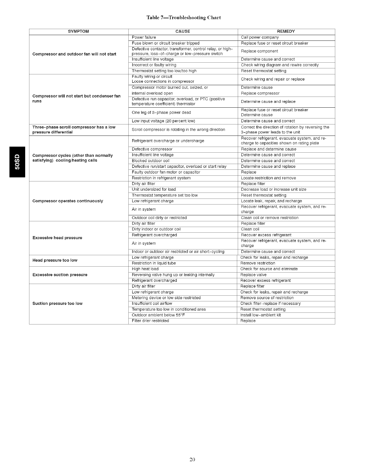
Table7--TroubleshootingChart
SYMPTOM
Compressor and outdoor fan will not start
Compressor win not start but condenser fan
FUnS
Three=phase scroll sompressor has a low
pressure differential
Compressor cycles (other than normally
satisfying) cooling/heating sails
Compressor operates continuously
Excessive head pressure
Head pressure too low
Excessive suction pressure
Suction pressure too low
CAUSE
Power failure
Fuse blown sr circuit breaker tripped
Defective contactor, transformer, control relay, or high-
pressure, loss-of-charge or low-pressure switch
Insufficient line voltage
Incorrect or faulty wiring
Thermostat setting too low/too high
Faulty wiring or circuit
Loose connections in compressor
Compressor motor burned out, seized, or
internal overload open
Defective run capacitor, overload, or PTC (positive
temperature coefficient) thermistor
One leg of 3-phase power dead
Low input voltage (20 percent low)
Scroll compressor is rotating in the wrong direction
Refrigerant overcharge or undercharge
Defective compressor
Insufficient line voltage
Blocked outdoor coil
Defective run/start capacitor, overload or start relay
Faulty outdoor fan motor or capacitor
Restriction in refrigerant system
Dirty air filter
Unit undersized for load
Thermostat temperature set too low
Low refrigerant charge
Air in system
Outdoor coil dirty or restricted
Dirty air filter
Dirty indoor or outdoor coil
Refrigerant overcharged
Air in system
Indoor or outdoor air restricted or air short-cycling
Low refrigerant charge
Restriction in liquid tube
High heat load
Reversing valve hung up or leaking internally
Refrigerant overcharged
Dirty air filter
Low refrigerant charge
Metering device or low side restricted
Insufficient coil airflow
Temperature too low in conditioned area
Outdoor ambient below 55°F
Filter drier restricted
REMEDY
Call power company
Replace fuse sr reset circuit breaker
Replace component
Determine cause and correct
Check wiring diagram and rewire correctly
Reset thermostat setting
Check wiring and repair or replace
Determine cause
Replace compressor
Determine cause and replace
Replace fuse or reset circuit breaker
Determine cause
Determine cause and correct
Correct the direction of rotation by reversing the
3-phase power leads to the unit
Recover refrigerant, evacuate system, and re-
charge to capacities shown on rating plate
Replace and determine cause
Determine cause and correct
Determine cause and correct
Determine cause and replace
Replace
Locate restriction and remove
Replace filter
Decrease load sr increase unit size
Reset thermostat setting
Locate leak, repair, and recharge
Recover refrigerant, evacuate system, and re-
charge
Clean coil or remove restriction
Replace filter
Clean coil
Recover excess refrigerant
Recover refrigerant, evacuate system, and re-
charge
Determine cause and correct
Check for leaks, repair and recharge
Remove restriction
Check for source and eliminate
Replace valve
Recover excess refrigerant
Replace filter
Check for leaks, repair and recharge
Remove source of restriction
Check filter replace if necessary
Reset thermostat setting
Install low-ambient kit
Replace
2O
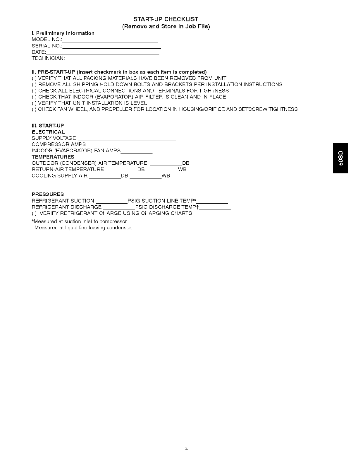
I. Preliminary information
MODEL NO.:
SERIAL NO.:
DATE:
TECHNICIAN:
START-UP CHECKLIST
(Remove and Store in Job File)
li. PRE-START=UP (Insert checkmark in box as each item is completed)
) VERIFY THAT ALL PACKING MATERIALS HAVE BEEN REMOVED FROM UNIT
) REMOVE ALL SHIPPING HOLD DOWN BOLTS AND BRACKETS PER INSTALLATION INSTRUCTIONS
) CHECK ALL ELECTRICAL CONNECTIONS AND TERMINALS FOR TIGHTNESS
) CHECKTHAT INDOOR (EVAPORATOR) AIR FILTER IS CLEAN AND IN PLACE
) VERIFY THAT UNIT INSTALLATION IS LEVEL
( ) CHECK FAN WHEEL, AND PROPELLER FOR LOCATION IN HOUSING/ORIFICE AND SETSCREW TIGHTNESS
III. START-UP
ELECTRICAL
SUPPLY VOLTAGE
COMPRESSOR AMPS
INDOOR (EVAPORATOR) FAN AMPS
TEMPERATURES
OUTDOOR (CONDENSER) AIR TEMPERATURE
RETURN-AIR TEMPERATURE DB
COOLING SUPPLY AIR DB WB
DB
WB
PRESSURES
REFRIGERANT SUCTION PSIG SUCTION LINE TEMP*
REFRIGERANT DISCHARGE PSIG DISCHARGE TEMPt
( ) VERIFY REFRIGERANT CHARGE USING CHARGING CHARTS
*Measured at suction inlet to compressor
1-Measured at liquid line leaving condenser.
21
Copyright 2007 Carrier Corporation Printed in the US.A. Edition Date: 07/07
Manufacturer reserves the right to change, at any time_ specifications and design without notice and without obligation.
22
Catalog No: 50SD-7Sl
Replaces: 50SD-6SI
