CARRIER Package Units(both Units Combined) Manual L0803488
User Manual: CARRIER CARRIER Package Units(both units combined) Manual CARRIER Package Units(both units combined) Owner's Manual, CARRIER Package Units(both units combined) installation guides
Open the PDF directly: View PDF ![]() .
.
Page Count: 22
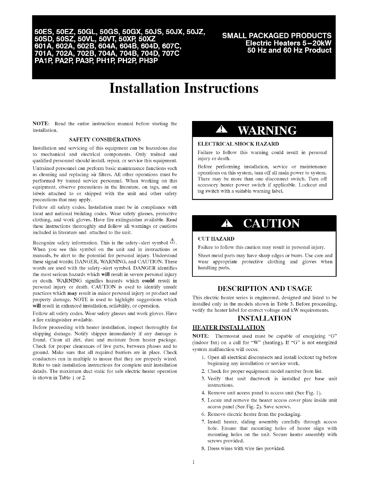
Installation Instructions
NOTE: Read the entire instruction manual before starting the
installation.
SAFETY CONSIDERATIONS
Installation and servicing of this equipment can be hazardous due
to mechanical and electrical components. Only trained and
qualified personnel should install, repair, or service this equipment.
Untrained personnel can perform basic maintenance functions such
as cleaning and replacing air filters. All other operations must be
performed by trained service personnel. When working on this
equipment, observe precautions in the literature, on tags, and on
labels attached to or shipped with the unit and other safety
precautions that may apply.
Follow all safety codes. Installation must be in compliance with
local and national building codes. Wear safety glasses, protective
clothing, and work gloves. Have fire extinguisher available. Read
these instructions thoroughly and follow all warnings or cautions
included in literature and attached to the unit.
Recognize safety information. This is the safety-alert symbol _.
When you see this symbol on the unit and in instructions or
manuals, be alert to the potential for personal injury. Understand
these signal words: DANGER, WARNING, and CAUTION. These
words are used with the safety-alert symbol. DANGER identifies
the most serious hazards which win result in severe personal injury
or death. WARNING signifies hazards which could result in
personal injury or death. CAUTION is used to identify unsafe
practices which may result in minor personal injury or product and
property damage. NOTE is used to highlight suggestions which
will result in enhanced installation, reliability, or operation.
Follow all safety codes. Wear safety glasses and work gloves. Have
a fire extinguisher available.
Before proceeding with heater installation, inspect thoroughly for
shipping damage. Notify shipper immediately if any damage is
found. Clean all dirt, dust and moisture from heater package.
Check for proper clearances of live parts, between phases and to
ground. Make sure that all required barriers are in place. Check
conductors run in multiple to insure that they are properly wired.
Refer to unit installation instructions for complete unit installation
details. The maximum duct static for safe electric heater operation
is shown in Table 1 or 2.
ELECTRICAL SHOCK HAZARD
Failure to follow this warning could result in personal
injury or death.
Before performing installation, service or maintenance
operations on this system, turn off all main power to system.
There may be more than one disconnect switch. Turn off
accessory heater power switch if applicable. Lockout and
tag switch with a suitable warning label.
(?liT HAZARD
Failure to follow this caution may result in personal injury.
Sheet metal parts may have sharp edges or burrs. Use care and
wear appropriate protective clothing and gloves when
handling parts.
DESCRIPTION AND USAGE
This electric heater series is engineered, designed and listed to be
installed only in the models shown in Table 3. Before proceeding,
verify the heater label for correct voltage and kW requirements.
INSTALLATION
HEATER INSTALLATION
NOTE: Thermostat used must be capable of energizing "G"
(indoor fan) on a call for "W" (heating). If "G" is not energized
system malfunction will occur.
1. Open all electrical disconnects and install lockout tag before
beginning any installation or service work.
2. Check for proper equipment model number from list.
3. Verify that unit ductwork is installed per base unit
instructions.
4. Remove unit access panel to access unit (See Fig. 1).
5. Locate and remove the heater access cover plate inside unit
access panel (See Fig. 2). Save screws.
6. Remove electric heater from the packaging.
7. Install heater, sliding assembly carefully through access
hole. Ensure that mounting holes of heater align with
mounting holes on the unit. Secure heater assembly with
screws provided.
8. Dress wires with wire ties provided.

ELECTRICALCONNECTION
1.Openallelectricaldisconnectsandinstalllockouttagbefore
beginninganyinstallationorservicework.
2.Allelectricalconnections,wiresizesandtypeofconduit
shallmeettheNationalElectricCode(NEC)andstateand
localcodes(orInternationalElectricCode)asapplicable.
Mainpowersupply,minimumwiresizes,circuits,fusing,
etc.areshownonschematicwiringdiagrams.
NOTE:Useminimum75°Ccopperwireonly.
3.Referto baseunitinstructionsforrecommendedwiring
procedures.
4.Connectlowvoltagewiresasshowninunitschematic
diagrams.Theseconnectionsmustbemadein the24v
barriersectioninsidetheunitpanel(SeeFig.2).
5.Connectfield power wiring as shown in heater wMng
diagram. All connections should be made inside the unit
and comply with the NEC and International Electric
Code and state and local codes. Heaters with factory
installed fuses may be installed on a branch circuit
protected by either a fuse or circuit breakel: For all
other heaters, the branch circuit must be protected by a
fuse or circuit breaker supplied by others.
6. Make all high voltage wire splice connections inside the
unit control box. Use splice connectors provided. Properly
insulate connectors. Separate all wires from incoming
power leads.
7. For fused heaters, incoming power leads should be strain
relieved. After attaching field power wires to the fuse block
lugs, use the pre-mounted wire tie on the inside of the
control box cover to secure and strain relieve these wires.
NOTE: The adjacent heater compressor contactor and low voltage
wiring are factory strain relieved in a similar manner.
8. Be sure that all electrical terminal connections, clamps,
screws, etc. are tight before proceeding.
9. Check wiring diagram supplied with heater for specific
connections and information.
10. Check operation as described in Start-Up section.
ELECTRICAL SHOCK HAZARD
Failure to follow this warning could result in personal
injury or death.
Before performing installation, service or maintenance
operations on this system, turn off all main power to system.
There may be more than one disconnect switch. Turn off
accessory heater power switch if applicable. Lockout and
tag switch with a suitable warning label.
START-UP
ELECTRICAL SHOCK HAZARD
Failure to follow this warning could result in personal
injury or death.
Before proceeding, verify that all wiring is correct per
factory approved schematic. Notify factory immediately of
any discrepancies.
1. Refer to base unit installation instructions as required.
2. Check for loose terminal connections.
3. Check that all fuse and circuit breaker short circuit
interrupting ratings are adequate.
4. Turn on unit and heater power.
5. Set thermostat to call for heat.
6. Check operation of heater.
7. Check that airflow across the heater is at or above the
minimum recommended CFM requirement (See unit
installation instructions). Adjust indoor blower heat speed
as required. Check that duct system confornrs to static
pressure limits in Table 1 or 2.
NOTE: See Table 1 for Non-Export units (with -3. -5 or -6 as
electrical option-see product data). See Table 2 for Export units
(with -9 as electrical option-see product data).
8. Any modifications or repairs to this equipment without
written permission from the factory will be done at the
installer's own risk and expense.
TROUBLESHOOTING
1. Fuses - Malfunction will interrupt power to the unit. Check
for cause of failure, replace fuses.
2. Limit Switch - Malfunction prevents heating element(s)
from being energized. Replace switch if malfunction occurs.
3. Contactor - Malfunction will not allow heater to energize.
Replace faulty contactor. Do not attempt to replace coil or
dress contacts.
PACKAGE CONTENTS
Electric Heater Package Contents
1. Heater assembly
2. UPC heater label
3. Installation instructions
4. Identification label
5. Schematic on lid door for all fused units
6. Schematic on sticker to be placed inside unit panel for
non-fused units
7. Wire connectors (3)
8. Wire ties-6-in. (5)
9. Screws #10A (5)
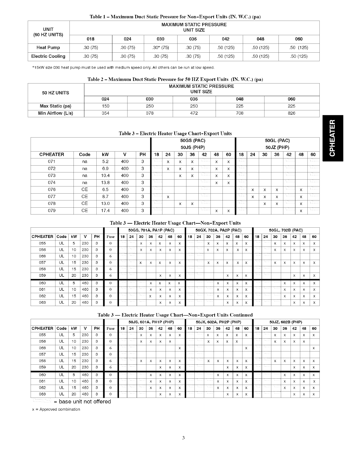
Table1-Maximum Duct Static Pressure for Non-Export Units (IN. W.C.) (pa)
MAXIMUM STATIC PRESSURE
UNIT UNIT SIZE
(60 HZ UNITS) 018 024 030 036 042 048 060
Heat Pump .30 (75) .30 (75) .30" (75) .30 (75) .50 (125) .50 (125) .50 (125)
Electric Cooling .30 (75) .30 (75) .30 (75) .30 (75) .50 (125) .50 (125) .50 (125)
*15kW size 030 heat pump must be used with medium speed only. All ethers can be run at towspeed.
Table 2-Maximum Duct Static Pressure for 50 HZ Export Units (IN. W.C.) (pa)
MAXIMUM STATIC PRESSURE
50 HZ UNITS UNIT SIZE
024 030 036 048 060
Max Static (pa) 150 250 250 225 225
Min Airflow (L/e) 354 378 472 708 826
Table 3 - Electric Heater Usage Chart-Export Units
50GS (PAC) 50GL (PAC)
50JS (PHP) 50JZ (PHP)
CPHEATER Code kW V PH 18 24 30 36 42 48 60 18 24 30 36 42 48 60
071 na 5.2 400 3 x x x x x
072 na 6,9 400 3 x x x x x
073 na 10.4 400 3 x x x x
074 na 13.8 400 3 x x
076 CE 6.5 400 3 x x x x
077 CE 8.7 400 3 x x x x x
078 CE 13.0 400 3 x x x x x
079 CE 17.4 400 3 x x x
Table 3-- Electric Heater Usage Chart--Non-Export Units
50GS, 701A, PAIP (PAC) 50GX, 702A, PA2P (PAC) 50GL, 702B (PAC)
CPHEATER Code kW V PH Fuse 18 24 30 36 42 48 60 18 24 30 36 42 48 60 18 24 30 36 42 48 60
X X X X X X X X X X X X X X X
XXXXX XXX XX XXXX X
X X X X X X X X X X X X X X X
X X X X X X X X X
055 UL 5 230 3 0
056 UL 10 230 3 0
068 UL 10 230 3 6
057 U L 15 230 3 0
058 UL 15 230 3 6
059 UL 20 230 3 6
060 UL 5 460 3 0
061 UL 10 460 3 0
062 U L 15 460 3 0
063 UL 20 460 3 0
X X X X X X X X X X X X
X X X X X X X X X X X X
X X X X X X X X X X X X
X X X X X X X X X
Table 3-- Electric Heater Usage Chart--Non-Export Units Continued
50J$, 601A, PH1P (PHP) 50JX, 602A, PH2P(PHP) 50JZ, 602B (PHP)
CPHEATER Code kW V PH Fuse 18 24 30 36 42 48 60 18 24 30 36 42 48 60 18 24 30 36 42 48 60
XXXXX XXXXX XXXXX
XXXX XXXX XXXX
X X X
XXXXX XXXXX XXXXX
055 UL 5 230 3 0
056 UL 10 230 3 0
068 UL 10 230 3 6
057 U L 15 230 3 0
058 UL 15 230 3 6
059 UL 20 230 3 6
060 UL 5 460 3 0
061 UL 10 460 3 0
062 U L 15 460 3 0
063 UL 20 460 3 0
= base unit not offered
x = Approved combination
XXX XXX XXX
XXXX XXXX XXXX
XXXX XXXX XXXX
XXXX XXXX XXXX
XXX XXX XXX
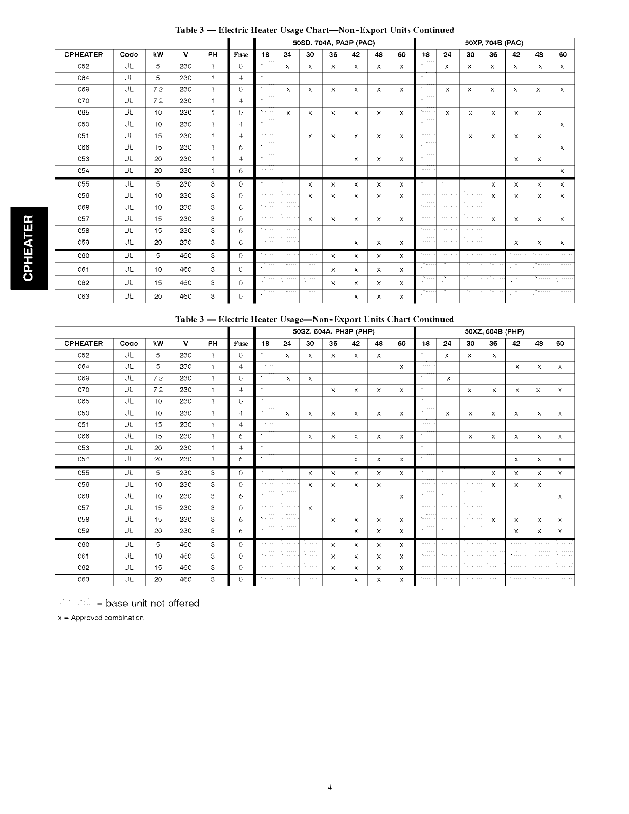
Table 3-- Electric Heater Usage Chart--Non-Export Units Continued
50$D, 704A, PA3P (PAC) 50XP, 704B (PAC)
CPHEATER Code kW V PH Fuse 18 24 30 36 42 48 60 18 24 30 36 42 48 60
052
064
069
070
065
050
051
066
053
054
055
056
068
057
O58
O59
O6O
061
062
063
UL 5 230 1
UL 5 230 1
UL 7,2 230 1
UL 7,2 230 1
UL 10 230 1
UL 10 230 1
UL 15 230 1
UL 15 230 1
UL 20 230 1
UL 20 230 1
UL 5 230 3
UL 10 230 3
UL 10 230 3
UL 15 230 3
UL 15 230 3
UL 20 230 3
UL 5 460 3
UL 10 460 3
UL 15 460 3
UL 20 460 3
0 X X X X X X X X X X X X
4
0 X X X X X X X X X X X X
4
0 XXXXX X XX XXX
4 X
4 X X X X X X X X X
6 X
4 X X X X X
d X
0 XXXX X XXXX
0 XXXX X XXXX
6
0 XXXX X XXXX
6
6 X X X X X X
0 X X X X ......
0 X X X X
0 X X X X ......
,, ,,, ,,,
0 X X X ......
Table 3 -- Electric Heater Usage---Non-Export Units Chart Continued
50SZ, 604A, PH3P (PHP) 50XZ, 604B (PHP)
CPHEATER Code kW V PH Fuse 18 24 30 36 42 48 60 18 24 30 36 42 48 60
052 UL 5 230 1 0 x x x x x x x x
064 UL 5 230 1 4 x x x x
069 UL 7,2 230 1 0 x x x
070 UL 7,2 230 1 4 x x x x x x x x x
065 UL 10 230 1 0
050 UL 10 230 1 4 x x x x x x x x x x x x
051 UL 15 230 1 4
066 UL 15 230 1 d x x x x x x x x x x
053 UL 20 230 1 4
054 UL 20 230 1 d x x x x x x
055 UL 5 230 3 0 x x x x x x x x x
056 UL 10 230 3 0 x x x x x x x
068 UL 10 230 3 6 x x
057 UL 15 230 3 0 x
058 UL 15 230 3 6 x x x x x x x x
059 UL 20 230 3 d x x x x x x
060 UL 5 460 3 0 x x x x ......
061 UL 10 460 3 0 x x x x ......
062 UL 15 460 3 0 x x x x ......
063 UL 20 460 3 0 x x x ......
= base unit not offered
x = Approved combination
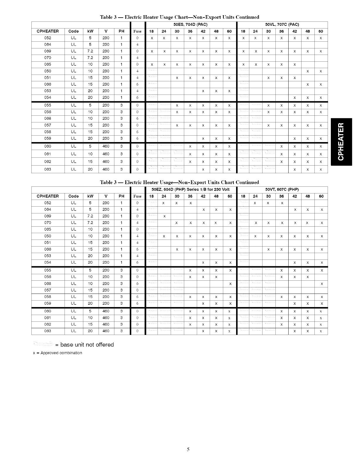
Table 3-- Electric Heater Usage (]hart Non-Export Units Continued
50ES, 704D (PAC) 50VL, 707C (PAC)
CPHEATER Code kW V PH Fuse 18 24 30 36 42 48 60 18 24 30 36 42 48 60
0 X X X X X X X X X X X X X X
4
0 X X X X X X X X X X X X X X
4
0 X X X X X X X X X X X X
UL 5 230 1
UL 5 230 1
UL 7,2 230 1
UL 7,2 230 1
UL 10 230 1
UL 10 230 1
UL 15 230 1
UL 15 230 1
UL 20 230 1
UL 20 230 1
UL 5 230 3
UL 10 230 3
UL 10 230 3
UL 15 230 3
UL 15 230 3
UL 20 230 3
UL 5 460 3
UL 10 460 3
UL 15 460 3
UL 20 460 3
O52
O64
O69
O7O
O65
O5O
051
O66
O53
O54
O55
O56
O68
O57
O58
O59
O6O
061
062
063
4 x x
4 x x x x x x x x
6 x x
4 x x x
6 x x x
0 xxxx x x xxxx
0 xxxx x x xxxx
0 XXXX X X XXXX
6
6 X X X X X X
0 XXX X XXXX
0 XXX X XXXX
0 XXX X XXXX
0 X X X X X X
Table 3 -- Electric Heater Usage---Non-Export Units Chart Continued
50EZ, 604D (PHP) Series 1/B for 230 Volt 50vr, 607c (PHP)
CPHEATER Code kW V PH Fuse 18 24 30 36 42 48 60 18 24 30 36 42 48 60
052 UL 5 230 1 0 x x x x x x
064 UL 5 230 1 4 x x x x x x
069 UL 7,2 230 1 0 x
070 UL 7,2 230 1 4 x x x x x x x x x x x
065 UL 10 230 1 0
050 UL 10 230 1 4 x x x x x x x x x x x x
051 UL 15 230 1 4
066 UL 15 230 1 6 x x x x x x x x x x
053 UL 20 230 1 4
054 UL 20 230 1 6 x x x x x x
055 UL 5 230 3 0 x x x x x x x x
056 UL 10 230 3 0 x x x x x x
068 UL 10 230 3 6 x x
057 UL 15 230 3 0 ....
058 UL 15 230 3 6 x x x x x x x x
059 UL 20 230 3 6 x x x x x x
060 UL 5 460 3 0 x x x x x x x x
061 UL 10 460 3 0 x x x x x x x x
062 UL 15 460 3 0 x x x x x x x x
063 UL 20 460 3 0 x x x x x x
= base unit not offered
x = Approved combination
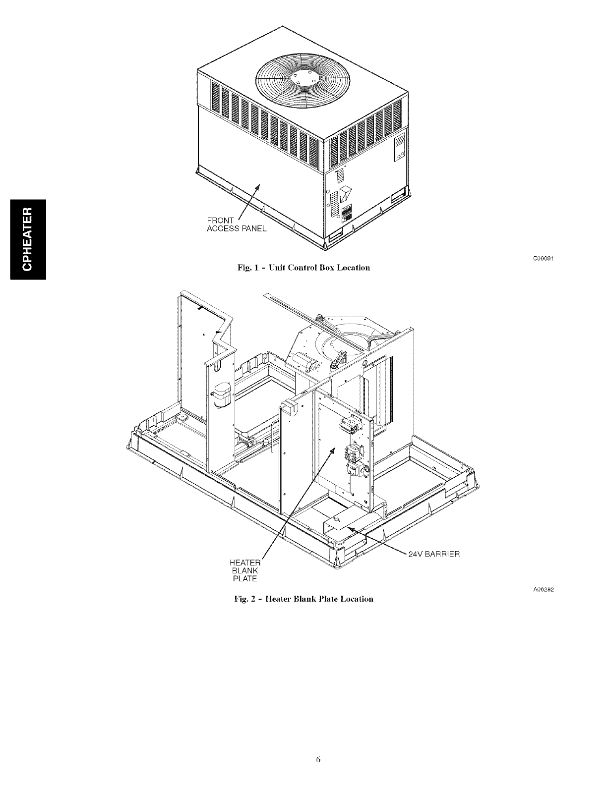
FRONT
ACCESS PANEL
Fig. 1 - Unit Control Box Location
C99091
HEATER
BLANK
PLATE
Fig. 2- Heater Blank Plate Location
• 24V BARRIER
A06282
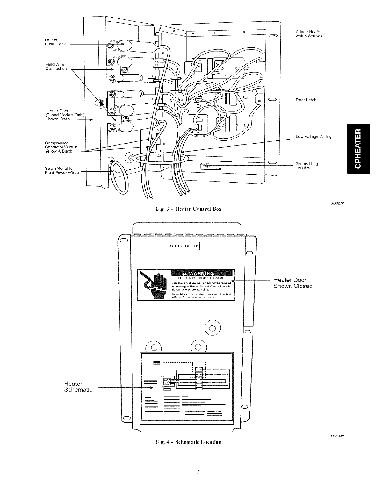
Heater
FuseBlock
FieldWire
Connection
\\(
Heater Door
(Fused Models Only I
Shown Open --
Compressor
Contactor Wire In
Yellow & Black _
Strain Relief for
Field Power Wires
Attach Heater
with 5 Screws
__ Door Latch
Low Voltage Wiring
Ground Lug
Location
Fig. 3- Heater Control Box
A06276
Heater
Schematic
m
C
i
i
i
i
Fig. 4-Schematic Location
Heater Door
Shown Closed
C01042
111001866
TOU_IITCONtrOL 2_ _
@
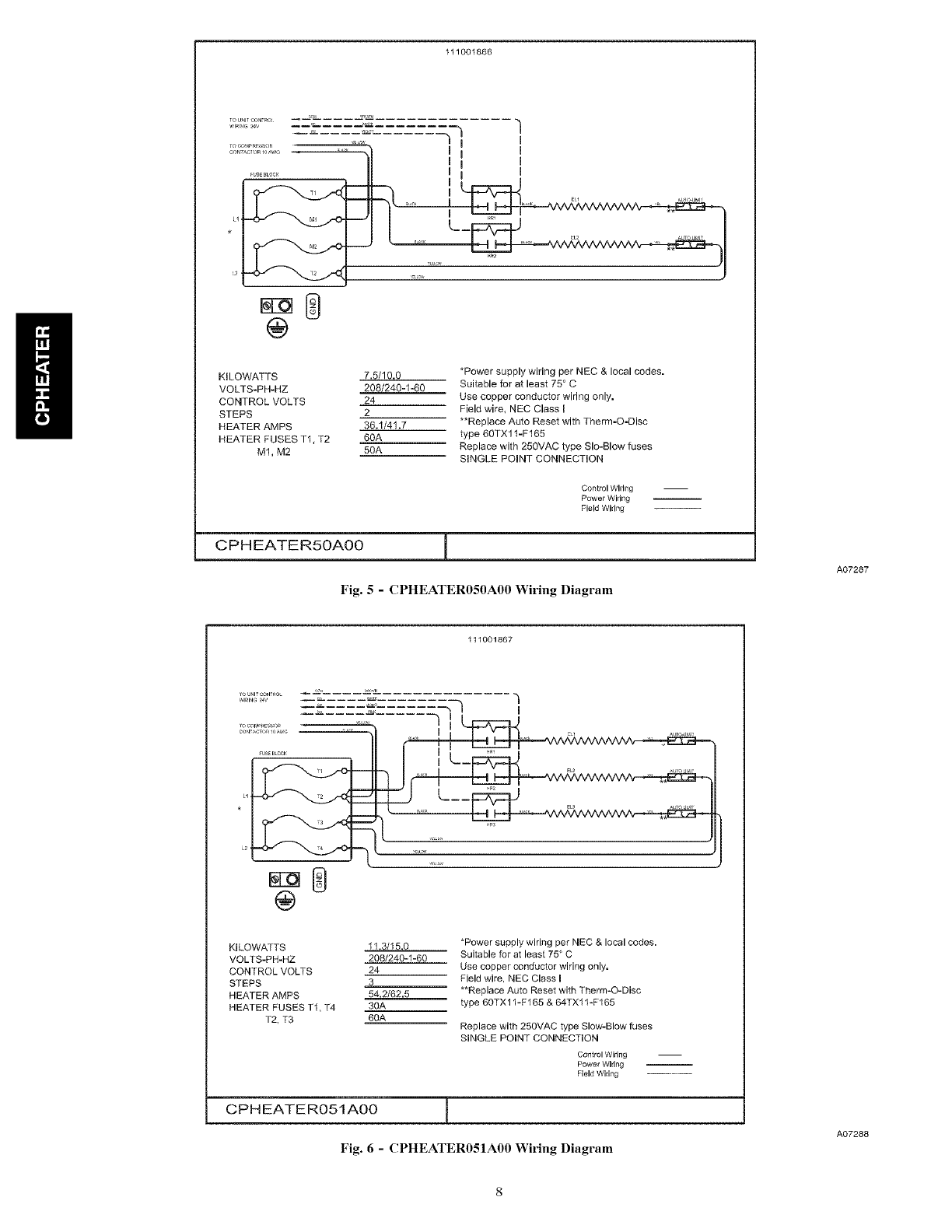
KmLOWATTS 7.5/10.0
VOLTS-PH-HZ 208/240-1-60
CONTROL VOLTS 24
STEPS 2
HEATER AMPS 36.1/41.7
HEATER FUSES T1, T2 60A
M1, M2 50A
*Power supply wiring per NEC & local codes.
Suitable for at least 75 ° C
Use copper conductor wiring only.
Field wire, NEC Class I
**Replace Auto Reset with Therm-O-Disc
type 60TX11-F165
Replace with 250VAC type Sle-Blow fuses
SINGLE POINT CONNECTION
Control Wiring
Power wiring
Field Wiring
CPHEATER5OAOO
Fig. 5- CPHEATER050A00 Wiring Diagram
A07287
111001867
.... _ -.... -'/ i
@
KILOWATTS 11.3/15.0
VOLTS-PH-HZ 208/240-1-80
CONTROL VOLTS 24
STEPS 3
HEATER AMPS 54.2/82.5
HEATER FUSES TI, T4 30A
T2, T3 60A
*Power supply wiring per NEC & local codes.
Suitable for at least 75 ° C
Use copper conductor wiring only.
Field wire, NEC Class I
**Replace Auto Reset with Therm-O-Disc
type 60TX11-F165 & 64TX11-F165
Replace with 250VAC type Slow-Blow fuses
SINGLE POINT CONNECTION
Control wiring
Power Wiring
Field Wiring
CPH EATER051AO0 1
Fig. 6 - CPHEATER051A00 Wiring Diagram
A07288
111001868
,............,_ I 0
................. I1"_ I I0
@
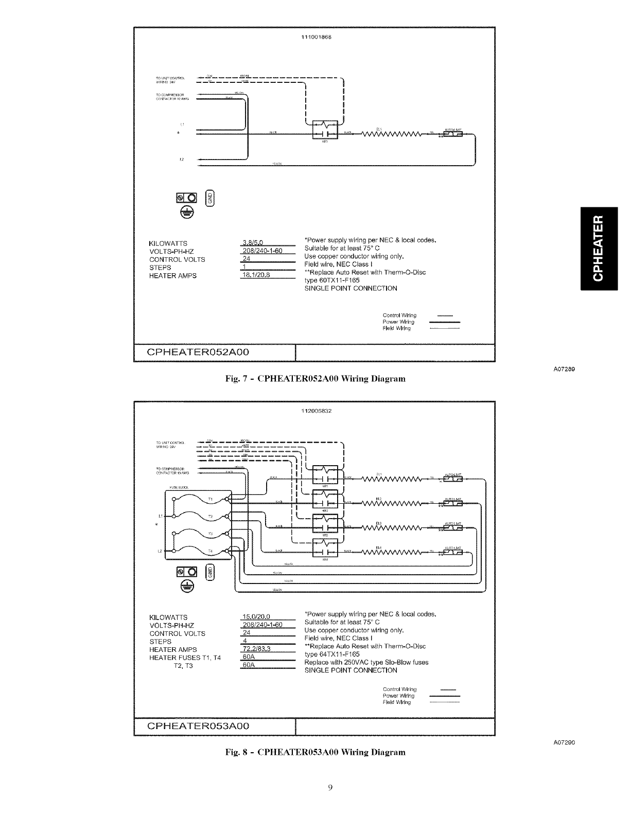
KILOWATTS _ /r
VOLTS-PH-HZ 208/240-1-60
CONTROL VOLTS 24
STEPS 1
HEATER AMPS 18.1/20.8
*Power supply wiring per NEC & local codes,
Suitable for at least 75 ° C
Use copper conductor wiring only.
Field wire, NEC Class I
**Replace Auto Reset with Therm-O-Disc
type 60TX11-F165
SINGLE POINT CONNECTION
Control Wiring
Power Wiring
Field Wiring
CPHEATERO52AOO 1
Fig. 7 - CPHEATER052A00 Wiring Diagram
112005832
A07289
KILOWATTS
VOLTS-PH-HZ
CONTROL VOLTS
STEPS
HEATER AMPS
HEATER FUSES T1, T4
T2, T3
15.0/20.0
208/240-1-60
24
4
72.2/83.3
60A
60A
*Power supply wiring per NEC & local codes.
Suitable for at least 75 ° C
Use copper conductor wiring only.
Field wire, NEC Class I
**Replace Auto Reset with Therm-O-Disc
type 64TXl 1-F165
Replace with 258VAC type Slo-Blow fuses
SINGLE POINT CONNECTION
Control Wiring
Power Wiring
Field Wiring
CPHEATERO53AO0 1
Fig. 8-CPHEATER053A00 Wiring Diagram
A07290
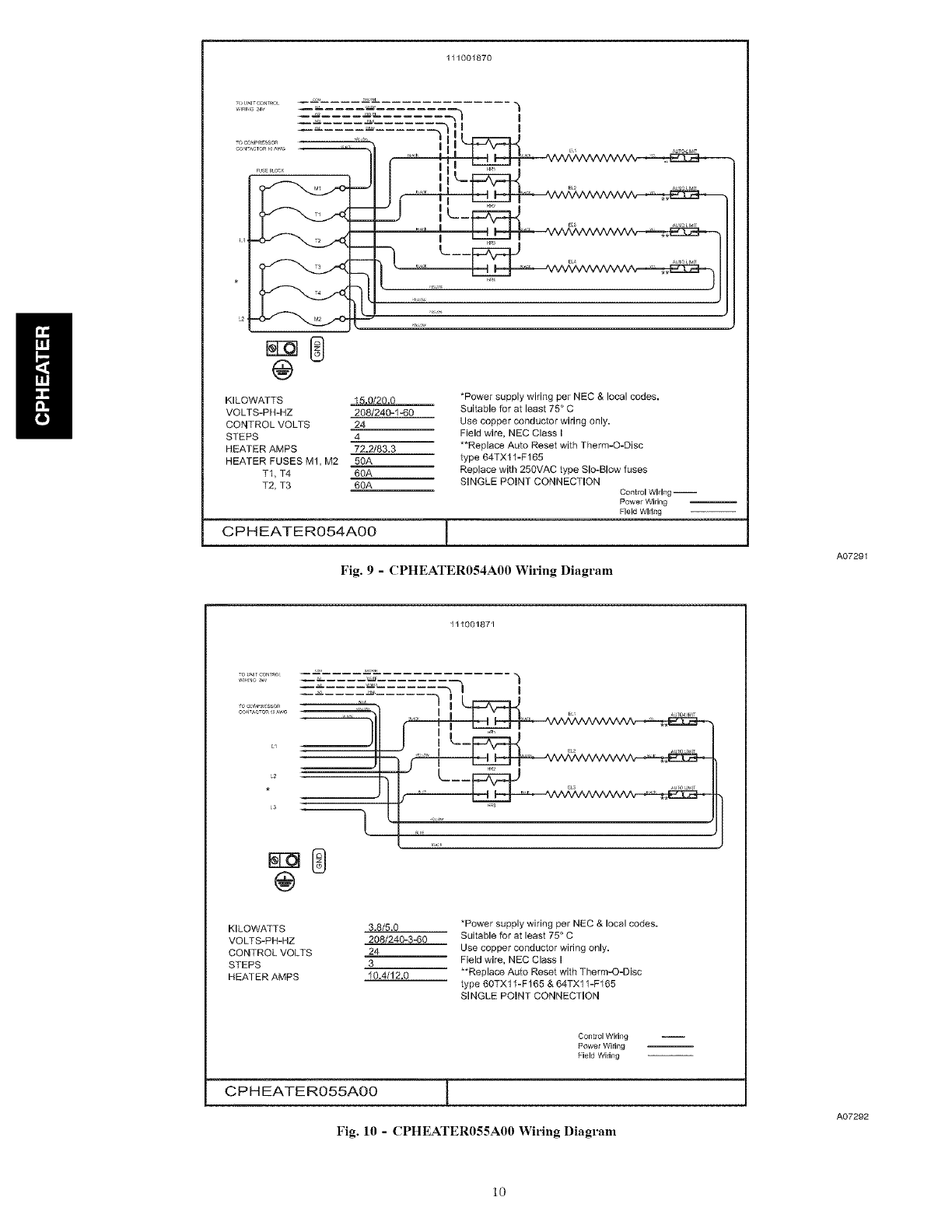
111001870
WlRI_IG_4V
FUSE BLOCK
@
I
_-311 I
I k I I I ,, II .........
/ llt__ _
....... I
KILOWATTS _ *Power supply wiring per NEC & local codes.
VOLTS-PH-HZ 208/240-1.-60 Suitable for at least 75 ° C
CONTROL VOLTS 24 Use copper conductor wiring only.
STEPS 4 Field wire, NEC Class I
HEATER AMRS 72.2/83.3 **Replace Auto Reset with Therm-O-Disc
HEATER FUSES M1, M2 50A type 64TX11-F165
TI, T4 68A Replace with 250VAC type Slo-Blow fuses
T2, T3 6OA SINGLE POINT CONNECTION Control wiring --
Power Wiring
Field Wldng
CPHEATERO54AO0 I
Fig. 9 -CPHEATER054A00 Wiring Diagram
111001871
A07291
TOU_ITCONT_O_
"---7 ..... -ql_
C2
@
t
KILOWATTS 3.8/5.0
VOLTS-PH-HZ 208/240-3-60
CONTROL VOLTS 24
STEPS 3
HEATER AMPS 10.4/12.0
.....C___ ., E_ _ ** u, ,
*Power supply wiring per NEC & local codes.
Suitable for at least 75 ° C
Use copper conductor wiring only.
Field wire, NEC Class I
**Replace Auto Reset with Therm-O-Disc
type 60TXll-F165 & 64TX11-F165
SINGLE POINT CONNECTION
Control Wiring
Power Wiring
Field Wiring
CPH EATER055A00 I
Fig. 10 -CPHEATER055A00 Wiring Diagram
A07292
10
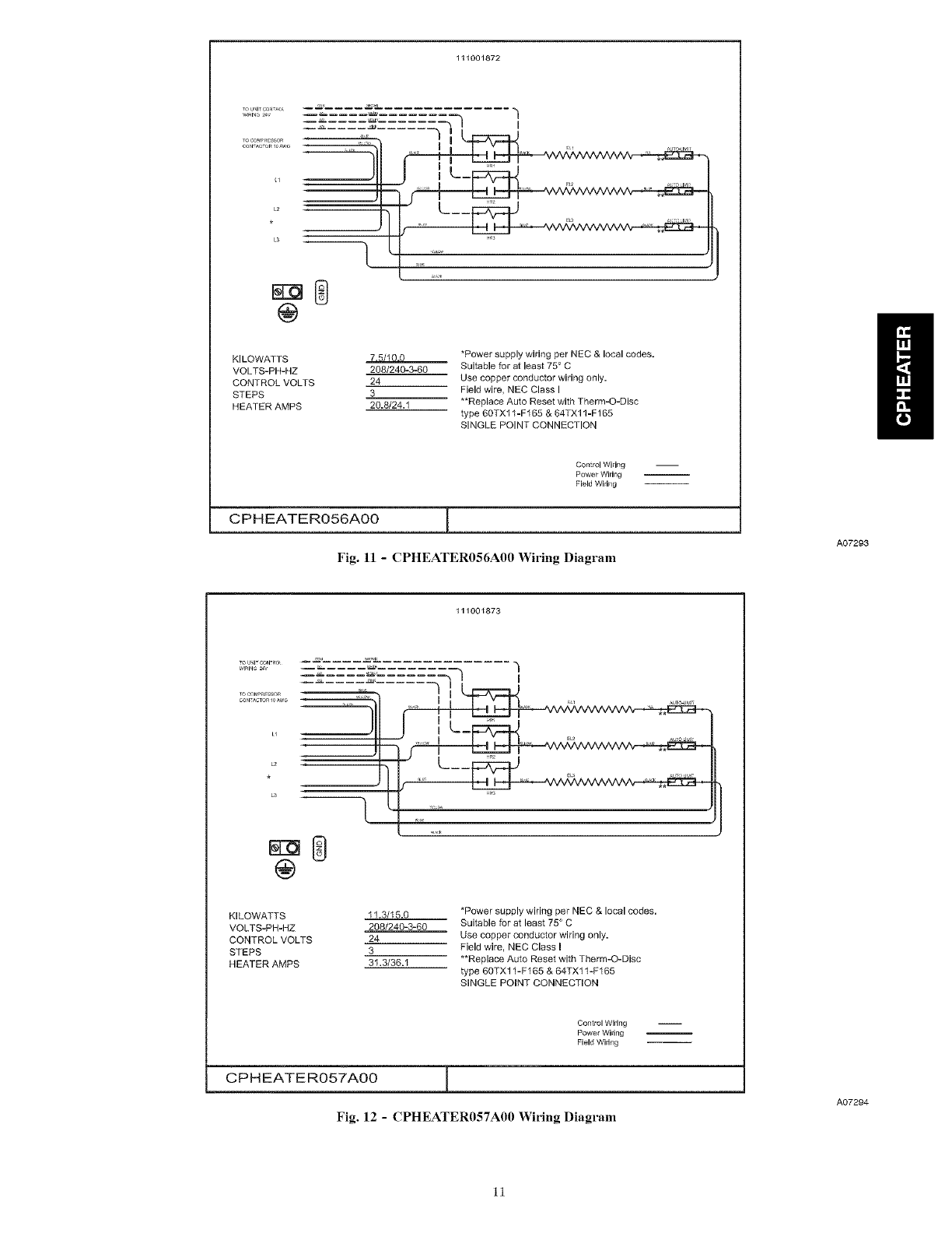
111001872
TOU_IT'_O_
COWAC_ORIOAWG
j ....
KILOWATTS 7 = I
VOLTS-PH-HZ 2081240-3-60
CONTROL VOLTS 24
STEPS 3
HEATER AMPS 20.8/24.1
*Power supply wiring per NEC & local codes.
Suitable for at least 750 C
Use copper conductor wiring only.
Field wire, NEC Class I
**Replace Auto Reset with Therm-O-Disc
type 60TXI 1-F165 & 64TXl 1-F165
SINGLE POINT CONNECTION
Control Wiring
Power Wiring
Field Wiring
CPHEATERO56AOO ]
Fig. 11 -CPHEATER056A00 Wiring Diagram
111001873
A07293
KILOWATTS 11.3/15.0
VOLTS-PH-HZ 208/240-3-60
CONTROL VOLTS 24
STEPS 3
HEATER AMPS 31.3/36.1
*Power supply wiring per NEC & local codes.
Suitable for at least 75 ° C
Use copper conductor wiring only.
Field wire, NEC Class I
**Replace Auto Reset with Therm-O-Disc
type 6OTXI 1-F165 & 64TXl 1-F165
SINGLE POINT CONNECTION
Control Wiring
Power Wiring
Field Wiring
CPHEATERO57AO0 1
Fig. 12 -CPHEATER057A00 Wiring Diagram
A07294
11
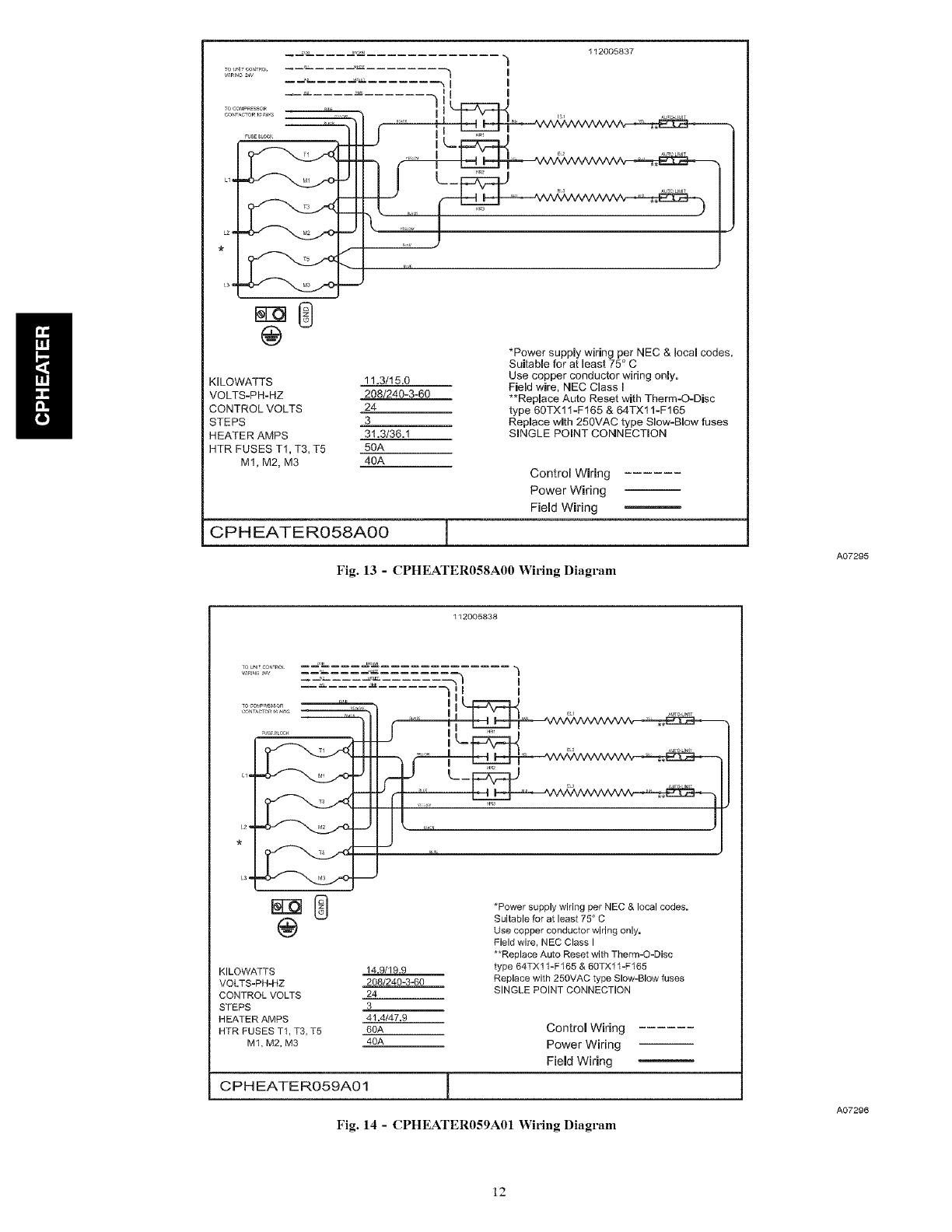
112005837
WIRINGTOUNIT CO_ITRO24V _ --_ -- -- -- _ .......
I I
,...... iI
.Lil
r IL-
,1-
@
KILOWATTS 11.3/15.0
VOLTS-PH-HZ 208/240-3-60
CONTROL VOLTS 24
STEPS 3
HEATER AMPS 31.3/36.1
HTR FUSES T1, T3, T5 50A
M1, M2, M3 40A
*Power supply wiring per NEC & local codes.
Suitable for at least 75 ° C
Use copper conductor wiring only.
Field wire, NEC Class I
**Replace Auto Reset with Therm-O-Disc
type 60TX11-Ft65 & 64TX11-F165
Replace with 250VAC type Slow-Blow fuses
SINGLE POINT CONNECTION
Control Wiring
Power Wiring
Field Wiring
CPHEATERO58AOO I
Fig. 13 - CPHEATER058A00 Wiring Diagram
112005838
A07295
@
KILOWATTS 14.9/19.9
VOLTS-PH-HZ 208/240-3-60
CONTROL VOLTS 24
STEPS 3
HEATER AMPS 41,4/47,9
HTR FUSES TI, T3, T5 60A
M1, M2, M3 40A
CPH EATER059A01
*Power supply wiring per NEC & local codes.
Suitable for at least 75 ° C
Use copper conductor wiring only,
Field wire, NEC Class I
**Replace Auto Reset with Therm-O-Disc
type 64TXl 1-F165 & 60TXl 1-F165
Replace with 250VAC type Slow-Blow fuses
SINGLE POINT CONNECTION
Control Wiring
Power Wiring
Field Wiring
Fig. 14 - CPHEATER059A01 Wiring Diagram
A07296
12

112005839
TO<_OMPRSSSOR
L2
L3
i/ i
J
I
_UT_UMF
LS, _L!
KmLOWATTS
VOLTS-PH-HZ
CONTROL VOLTS
STEPS
HEATER AMPS
5.0
480-3,-60
24
1
6.0
_Power supply wiring per NEC & local codes.
Suitable for at least 75 ° C
Use copper conductor wiring only,
Field wire, NEC Class i
**Replace Auto Reset with Therm-O-Disc
type 64TXX11-F165
SINGLE POINT CONNECTION
Control Wiring
Power wiring
Field Wiring
C PH EATERO6OAOO
Fig. 15 - CPHEATER060A00 Wiring Diagram
A07297
112005840
WIRING24V
TOCOM_R_SSOR
CO_TACTO_IOAW_
H
L2
L3
I
@
KILOWATTS
VOLTS-PH-HZ
CONTROL VOLTS
STEPS
HEATER AMPS
10.0
480-3..,60
24
1
12.0
*Power supply wiring per NEC & local codes.
Suitable for at least 75 ° C
Use copper conductor wiring only.
Field wire, NEC Class i
**Replace Auto Reset with Therm-O-Disc
type 64TXX11-F165
SINGLE POINT CONNECTION
Control Wiring i
Power Wiring
Field Wiring
CPHEATERO61AO0
Fig. 16 - CPHEATER061A00 Wiring Diagram
13
A07298
L1
L2
L3
@
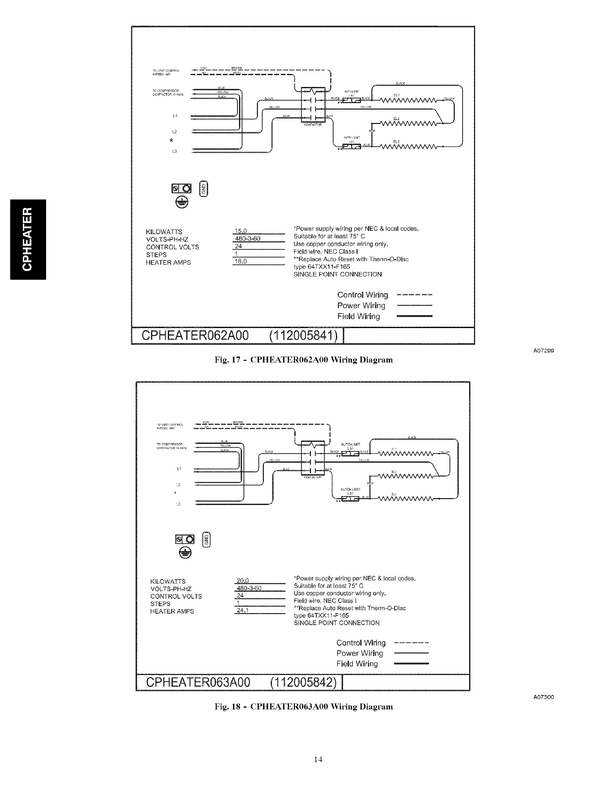
KILOWATTS 15.0
VOLTS-PH-HZ 480-3-60
CONTROL VOLTS 24
STEPS 1
HEATER AMPS 18.0
*Power supply wiring per NEC & local codes.
Suitable for at least 75 ° C
Use copper conductor wiring only.
Field wire, NEC Class I
**Replace Auto Reset with Therm-O-Disc
type 64TXXl 1-F165
SINGLE POINT CONNECTION
CPHEATER062A00
Control Wiring
Power Wiring
Field Wiring
(112005841 ) L
Fig. 17 - CPHEATER062A00 Wiring Diagram
A07299
co,., B_.._
t i
TOOF'F4P_ESSF_ _W AUTD-LIMIT
C@NTACTO_IOAWG LSI E
L2
LS
@
KILOWA_S 20.0
VOLTS-PH-HZ 480-3-60
CONTROL VOLTS 24
STEPS 1
HEATER AMPS 24,1
*Power supply wiring per NEC & local codes.
Suitable for at least 75° C
Use copper conductor wiring only.
Field wire, NEC Class I
**Replace Auto Reset with Therm-O-Disc
type 64TXX11 -F 166
SINGLE POINT CONNECTION
CPHEATER063A00
Control Wiring
Power Wiring
Field Wiring
(112005842) 1
Fig. 18 - CPHEATER063A00 Wiring Diagram
A07300
14
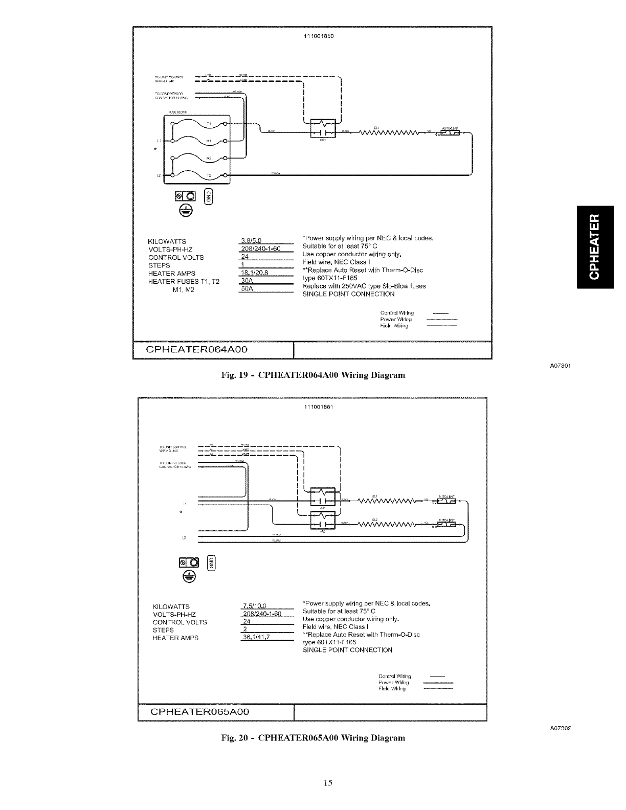
111001880
................. JL ..t:._ "l
WIRING 24V _ ..........
]1 I0
@
KILOWATTS 3.8/5.6
VOLTS-PH-HZ 208/240-140
CONTROL VOLTS 24
STEPS 1
HEATER AMPS 18.1/20.8
HEATER FUSES T1, T2 3OA
M1, M2 5OA
*Power supply wiring per NEC & local codes.
Suitable for at least 75 ° C
Use copper conductor wiring only,
Field wire, NEC Class m
**Replace Auto Reset with Therm-Q-Disc
type 60TX11-F165
Replace with 250VAC type Slo-Blow fuses
SINGLE POINT CONNECTION
Control Wiring
Power Wiring
Field wirif_g
CPHEATER064A00 [
Fig. 19 -CPHEATER064A00 Wiring Diagram
111001881
A07301
0I I
12
@
KILOWATTS 7.5/10.0
VOLTS-PH-HZ 208/240-1-60
CONTROL VOLTS 24
STEPS 2
HEATER AMPS 36.1/41,7
*Power supply wiring per NEC & local codes,
Suitable for at least 75 ° C
Use copper conductor wiring only.
Field wire, NEC Class I
**Replace Auto Reset with Therm-O-Disc
type 60TXl 1-F165
SINGLE POINT CONNECTION
Control Wiring
Power Wiring
Field Wldng
CPHEATERO65AOO ]
Fig. 20 -CPHEATER065A00 Wiring Diagram
A07802
]5
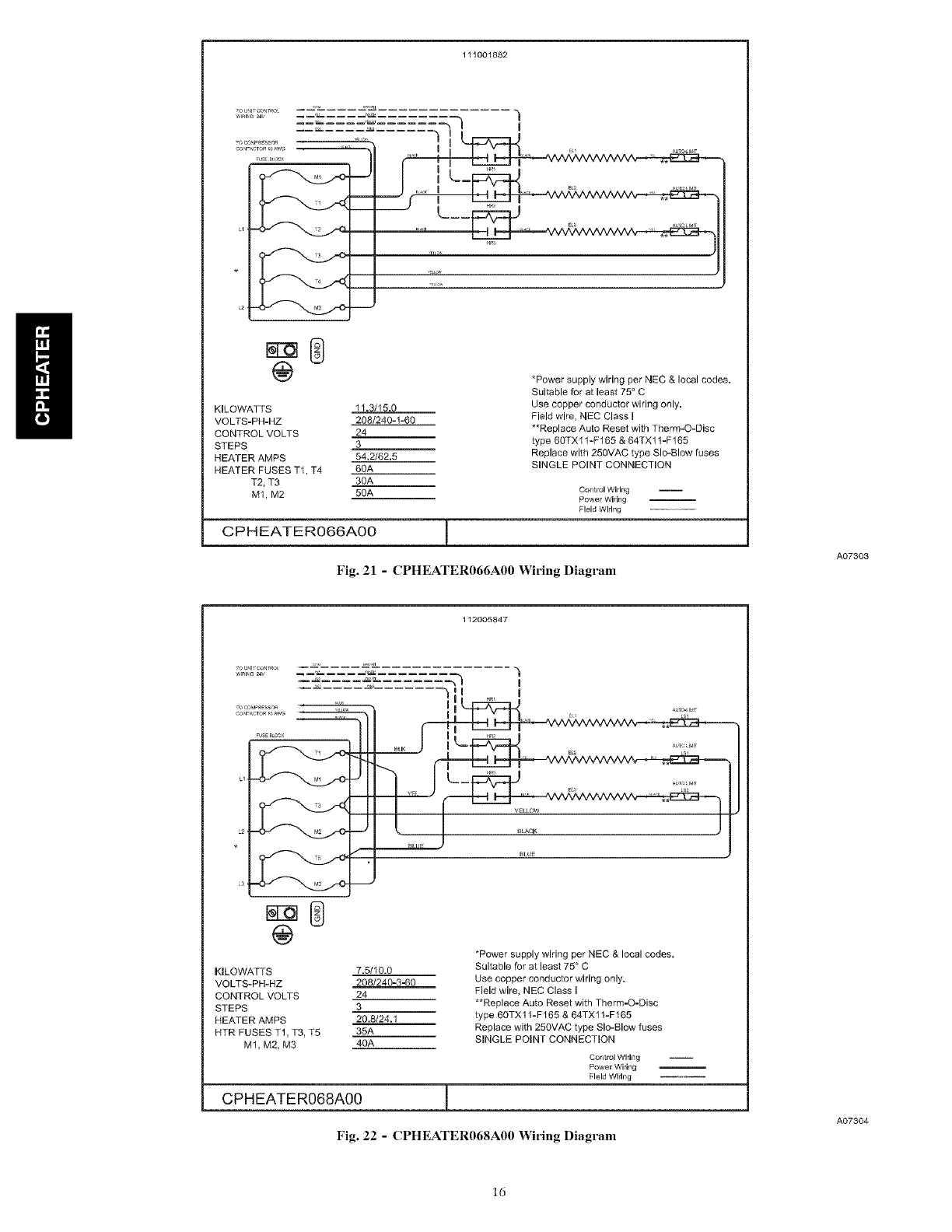
111001882
J-_-,,,.z_tj..c. _ _
L__
_o
_
KILOWATTS 11.3/15.0
VOLTS-PH-HZ 208/240-1-60
CONTROL VOLTS 24
STEPS 3
HEATER AMPS 54,2/62.5
HEATER FUSES T1, T4 60A
T2, T3 30A
M1, M2 50A
*Power supply wiring per NEC & local codes.
Suitable for at least 75 ° C
Use copper conductor wiring only,
Field wire, NEC Class I
**Replace Auto Reset with Therm-O-Disc
type 60TX 11-F165 & 64TX11 -F165
Replace with 250VAC type SIo.-Blow fuses
SINGLE POINT CONNECTION
Control Wiring
Power Wiring
Field Wiring
CPHEATERO66AO0 [
Fig. 21 - CPHEATER066A00 Wiring Diagram
112005847
A07303
KILOWATTS
VOLTS-PH-HZ
CONTROL VOLTS
STEPS
HEATER AMPS
HTR FUSES TI, T3, T5
M1, M2, M3
I RR_
Bo K -- I RR_
IR:
_1 _ E_ LS2
@
*Power supply wiring per NEC & local codes,
7.5/10.0 Suitable for at least 75 ° C
208/240-3.-60 Use copper conductor wiring only.
24 Field wire, NEC Class [
3 **Replace Auto Reset with Therm-O-Disc
20.8/24.1 type 60TX11-F165 & 64TX11-F165
35A Replace with 256VAC type Slo-Blow fuses
40A SINGLE POINT CONNECTION
CPHEATER068A00
Control Wiring
Power Wiring
Field Wiring
Fig. 22 -CPHEATER068A00 Wiring Diagram
A07304
ld
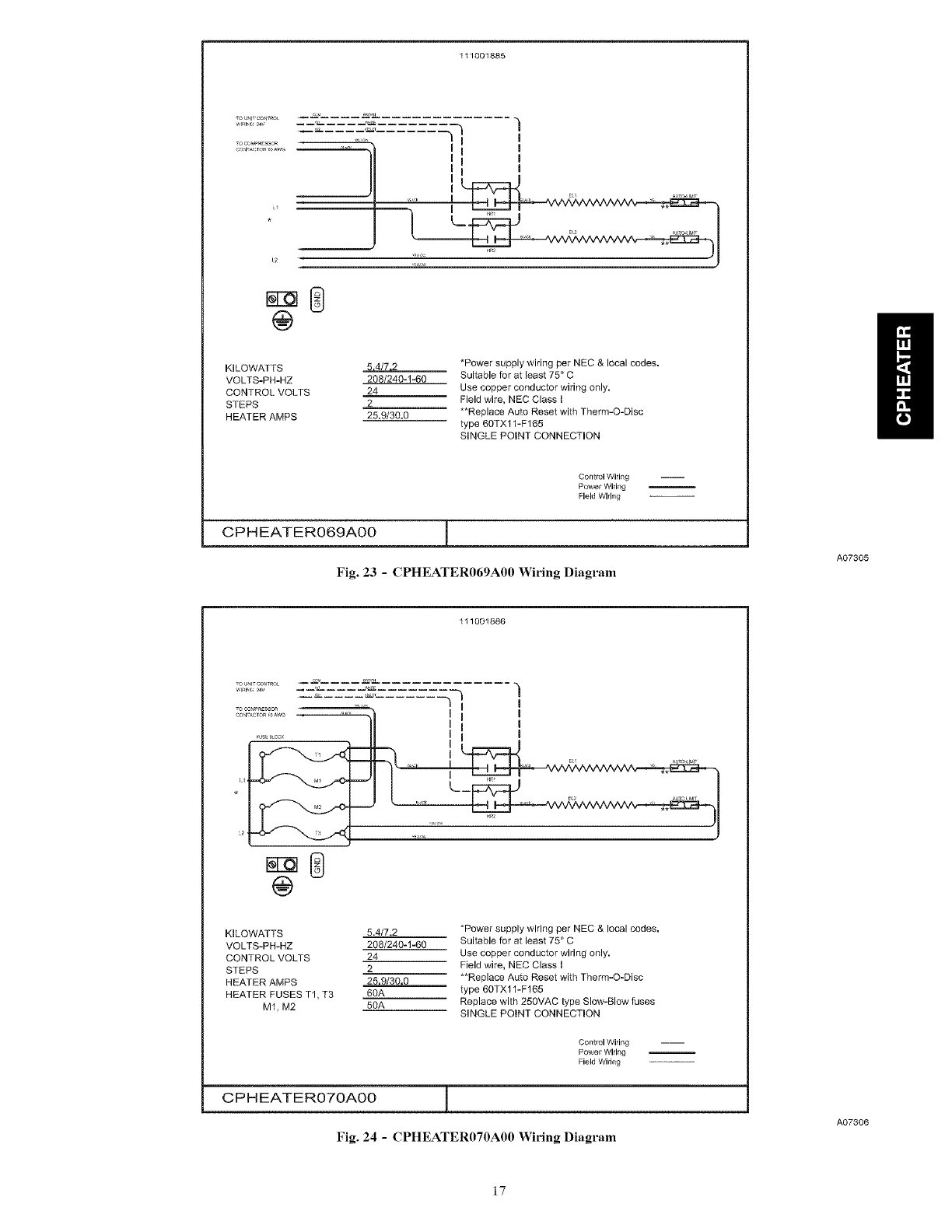
111001885
t
"fl I 'm I
II I i i
JI
t_ r _,, •
@
KILOWATTS 5,4 72/7,2
VOLTS-PH-HZ 208/240-1-60
CONTROL VOLTS 24
STEPS 2
HEATER AMPS 25.9/30.0
*Power supply wiring per NEC & local codes,
Suitable for at least 75 ° C
Use copper conductor wiring only.
Field wire, NEC Class I
**Replace Auto Reset with Therm-O-Disc
type 60TX11-F165
SINGLE POINT CONNECTION
Control Wiring
Power Wiring
Field Wiring
CPHEATERO69AO0 1
Fig. 23 -CPHEATER069A00 Wiring Diagram
111001886
A07305
w,......... --_,-_------_%-----------__-) "_
]1 I i I
...... II i 0i
.I -' ....
_ u
@
KILOWATTS 5.4/7.2
VOLTS-PH-HZ 208/240-1-60
CONTROL VOLTS 24
STEPS 2
HEATER AMPS 25,9/30,0
HEATER FUSES T1, T3 60A
M1, M2 5OA
*Power supply wiring per NEC & local codes,
Suitable for at least 75 ° C
Use copper conductor wiring only,
Field wire, NEC Class I
**Replace Auto Reset with Therm-O-Disc
type 60TX11-F165
Replace with 250VAC type Slow-Blow fuses
SINGLE POINT CONNECTION
Control Wiring
Power Wiring
Field Widng
CPHEATER070A00 j
Fig. 24 -CPHEATER070A00 Widng Diagram
A07306
17
ro_Ull¸cou_o_
0
/ -I I
L2
_------J .J
£5
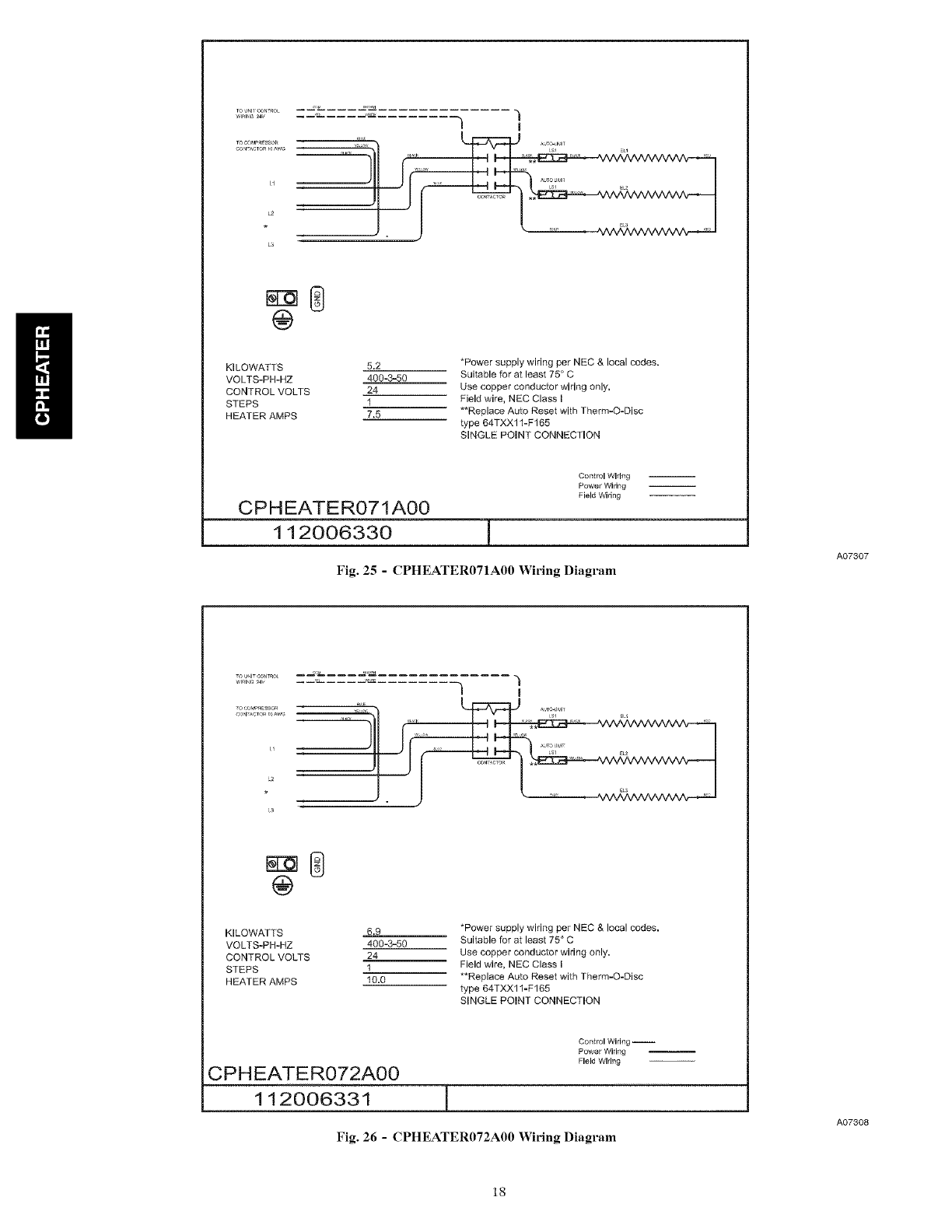
KILOWATTS 5.2
VOLTS-PI-I-HZ 400-3-50
CONTROL VOLTS 24
STEPS 1
HEATER AMPS 7,5
*Power supply wiring per NEC & local codes.
Suitable for at least 75 ° C
Use copper conductor wiring only.
Field wire, NEC Class I
**Replace Auto Reset with Therm-O-Disc
type 64TXX11-F165
SINGLE POINT CONNECTION
CPH EATE R071A00
112006330
Control Wiring
Power Wiring
Field Wiring
Fig. 25 -CPHEATER071A00 Wiring Diagram
A07307
|0
L2
•: L J
@
KILOWATTS 6.9
VOLTS-PH-HZ 400-3-50
CONTROL VOLTS 24
STEPS 1
HEATER AMPS 10.0
*Power supply wiring per NEC & local codes.
Suitable for at least 75 ° C
Use copper coflductor wiring only.
Field wire, NEC Class I
**Replace Auto Reset with Therm-O-Disc
type 64TXX11-F165
SINGLE POINT CONNECTION
CPHEATER072A00
112006331 1
Control Wiring --
Power Wiring
Field Wiring
Fig. 26 -CPHEATER072A00 Widng Diagram
A07308
18

@
KILOWATTS 10.4
VOLTS-PH-HZ 400-3-50
CONTROL VOLTS 24
STEPS 1
HEATER AMPS 15.0
*Power supply wiring per NEC & local codes.
Suitable for at least 75 ° C
Use copper conductor wiring only,
Field wire, NEC Class I
**Replace Auto Reset with Therm-O-Disc
type 64TXX11-F165
SINGLE POINT CONNECTION
Control Wiring
Power Wiring
Field WMng
CPHEATER073A00 (112006332) [
Fig. 27 -CPHEATER073A00 Wiring Diagram
A07309
L!
L2
KILOWATTS 13.8
VOLTS-PH-HZ 400-3-50
CONTROL VOLTS 24
STEPS 1
HEATER AMPS 20,0
*Power supply wiring per NEC & local codes.
Suitable for at least 75 ° C
Use copper conductor wiring only,
Field wire, NEC Class I
**Replace Auto Reset with Therm-O-Disc
type 64TXX11-F165
SINGLE POINT CONNECTION
CPHEATER074A00
Control Wiring
Power Wiring
Field Wiring
(112006333) [
Fig. 28 -CPHEATER074A00 Wiring Diagram
A07310
19
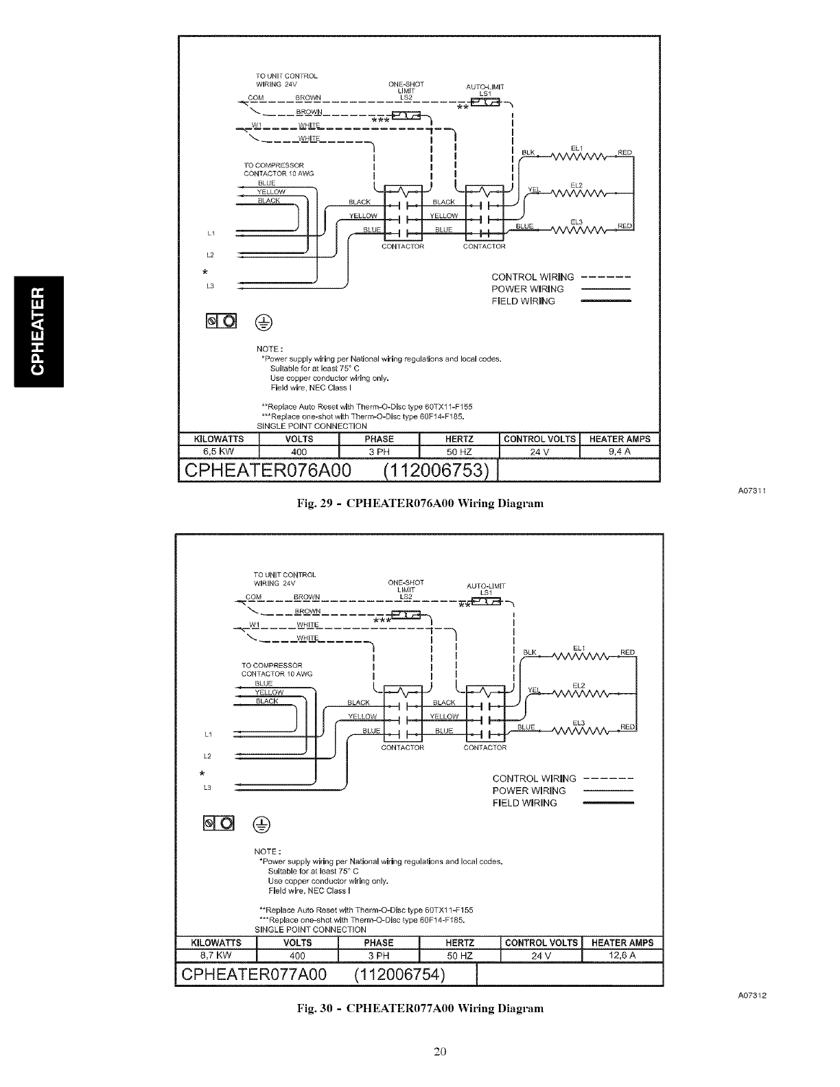
L1
L2
L3
tO UNIT CONTROL
WIRING 24V ONB_qHOT AUTO-LIMIT
LIMIT LSl
COM BROWN LS2
\ BROWN _._E_:Z__hI
W1 WHITE
-'- F-q I
\_ WHITE I
I I I Eu
10 COMPRESSOR I I I I
CONTACTOR 10AWG I I I I
BLUE EL2
_ I _ BLUE EL3 RED
__ ) #CONTROL WIRING
POWER WIRING
FIELD WIRING
T-Oq@
NOTE :
*Power supply wiring per Nalional wiring regulalions and local codes,
Suitable for at least 75 ° C
Use copper conductor wiring only,
Field wire, NEC Class I
**Replace Auto Reset with Therm-O-Disc type 6OTX11-F155
***Replace one-shot with Therm-O-Disc type 60F14-F185,
SINGLE POINT CONNECTION
KILOWATTS6,5KW VOLTS ! PHASE i HERTZ i CONTROL VOLTS [HEATERAMPS400 3 PH 50 HZ 24 V 9,4 A
CPHEATER076A00 (112006753) I
Fig. 29 - CPHEATER076A00 Wiring Diagram
A07311
L1
L2
L3
TO UNITCONTROL
WIRING 24V ONE.SHOT AUTO-LIMIT
LIMIT LSI
COM BROWN LS2
_'-_ BROWN
Wl WRITE _ _::_ F-h"_ WHITE
"_ I I EU
I I IBLK -- RED
TO COMPRESSOR I I I I I
CONTACTOR 10AWG I I I [ I
LF:: ::qJ LF: qJ I
___BLACK BLACK BLACK
POWER WIRING
FIELD WIRING
NOTE :
*Power supply wiring per National wiring regulations and local codes.
Suitable for at least 75 ° C
Use copper conductor wiring only.
Field wire, NEC Class I
**Replace Auto Reset witb Tberm-O-Disc type 60TXl 1-F155
***Replace one-shot with Therm,-O-Disc type 60F14-7185,
SINGLE POINT CONNECTION
KILOWATTS J VOLTS J PHASE _ HERTZ
8,7 KW I 400 ! 3 PH ! 50 HZ
CPHEATER077A00 (112006754) 1
[ CONTROL VOLTS [ HEATER AIVIPS
!24V I 12,6A
Fig. 30 -CPHEATER077A00 Wiring Diagram
A07312
2O
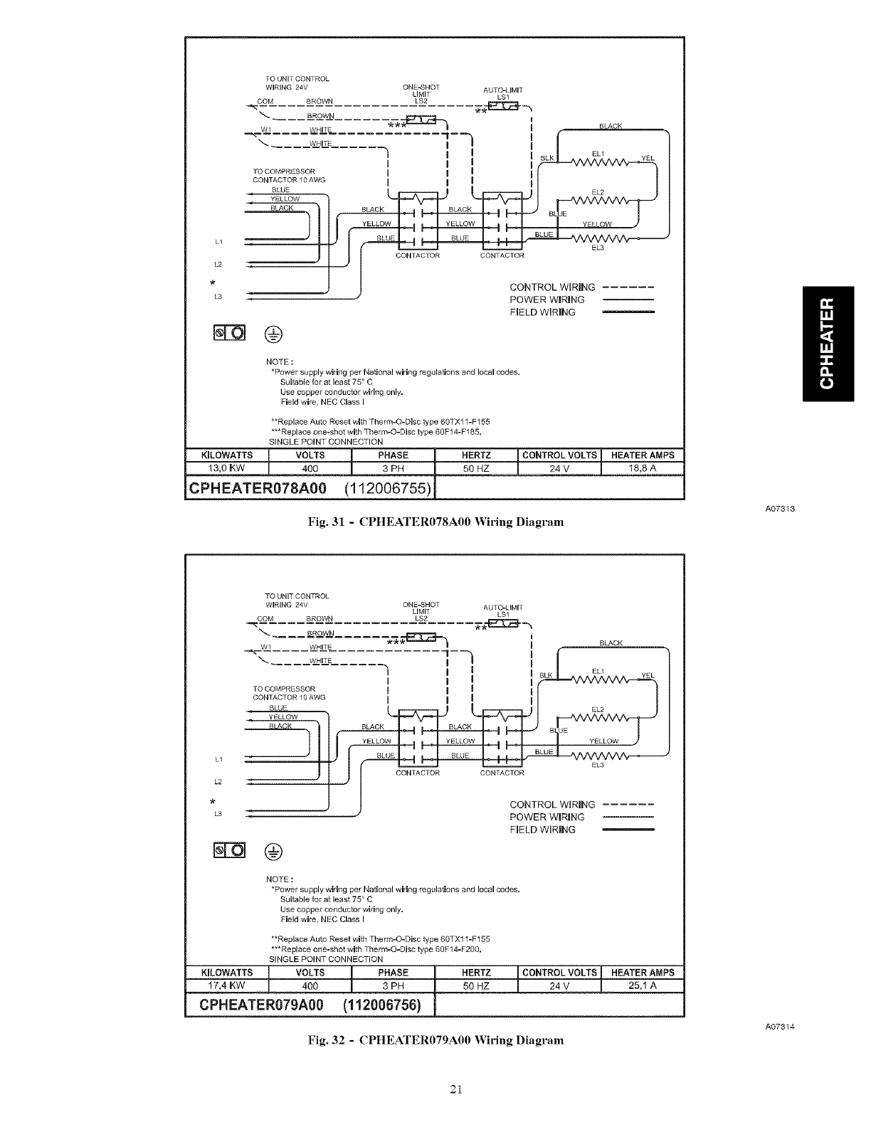
[O UNIT CONTROL
WIRING 24V ONE-SHOT AUTO-LIMIT
LIMIT LSl
COM BROWN LS2
BROWN .__._ I BLACK
Wl WHITE
EL1
IIBLK IA ^ ^ AEL2 ^ * ^ '{EL
I I I #_---- vv vv vv v v-_--h
]OCOMPRESSOR I
- I I I I I
CONTACTOR 10 AWG I [ I I I [
BLUE
BLACK BLACK BLACK
YELLOW
L2
•CONTROL WIRING
L3 POWER WIRING
FIELD WIRING
@
NOTE :
*Power supply wiring per National wiring regulations and local codes,
Suitable for at least 75 ° C
Use copper conductor wiring only,
Field wire, NEC Class I
**Replace Auto Reset with Therm-O-Disc type 60TX11-F155
***Replace one-shot with Therm-O-Disc type 60F14-F185,
SINGLE POINT CONNECTION
KILOWATTS]13,0KW VOLTS !PHASE400 3 PH HERTZ iCONTROL VOLTS [HEATERAMPS50HZ 24 V 18,8 A
CPHEATER078A00 (112006755)
Fig. 31 - CPHEATER078A00 Wiring Diagram
A07313
TO UNIT CONTROL
WIRING 24V ONE-SHOI AUTO-LIMIT
LIMIT LS1
COM BROWN LS2
WI WHI1_
-"-- I--% l (
WHITE . I ! I /
I I I / EL1 y
BLK EL
TO COMPRESSOR I I I [I I
CONTACTOR_0AWG ! I ! I I I
I CONTACTOR CONTACTOR
L2
* CONTROL WIRING
L3 POWER WIRING
FIELD WIRING
@
NOTE :
*Power supply wiring per National wiring regulations and local codes.
Suitable for at least 75 ° C
Use copper conductor wiring only,
Field wire. NEC Class I
**Replace Auto Reset with Therm-O-Disc type 6OTX1 l-F155
***Replace one-shot with Therm-O-Disc type 60F14-F200,
SINGLE POINT CONNECTION
KILOWATTS J VOLTS t PHASE HERTZ t CONTROL VOLTS17,4 KW 400 3 PH 50 HZ 24 V
CPHEATER079A00 (112006756)
tHEATER AhlPS
25,1 A
Fig. 32 -CPHEATER079A00 Wiring Diagram
A07314
21

Copyright 2008 CAC /BDP • 7310 W. Morris St. • indianapolis, iN 46231 Printed in U.SA Edition Date: 03/08
Manufacturer reserves the right to change_ at any time_ specifications and designs without notice and without obligations.
Catalog No: IIKCPHEATER-09
Replaces: IIKCPHEATER - 08
22
