CARRIER Humidifier Manual L0803491
User Manual: CARRIER CARRIER Humidifier Manual CARRIER Humidifier Owner's Manual, CARRIER Humidifier installation guides
Open the PDF directly: View PDF ![]() .
.
Page Count: 4
HUMiDiTRACTMHUMiDiFiERCONTROL
Safety and Installation Instructions
READ COMPLETE iNSTALLATiON iNSTRUCTiONS AND TEMPLATE BEFORE STARTING.
Attention Installer: This product must be installed by a qualified heating and air conditioning contractor.
Failure to do so could result in serious injury from electrical shock.
THESE iNSTALLATiON iNSTRUCTiONS ARE FORTHE HUMIDiTRAC TMHUMiDiFiER CONTROLONLY!
ForHumidifier installation, follow Humidifier Installation instructions.
/A
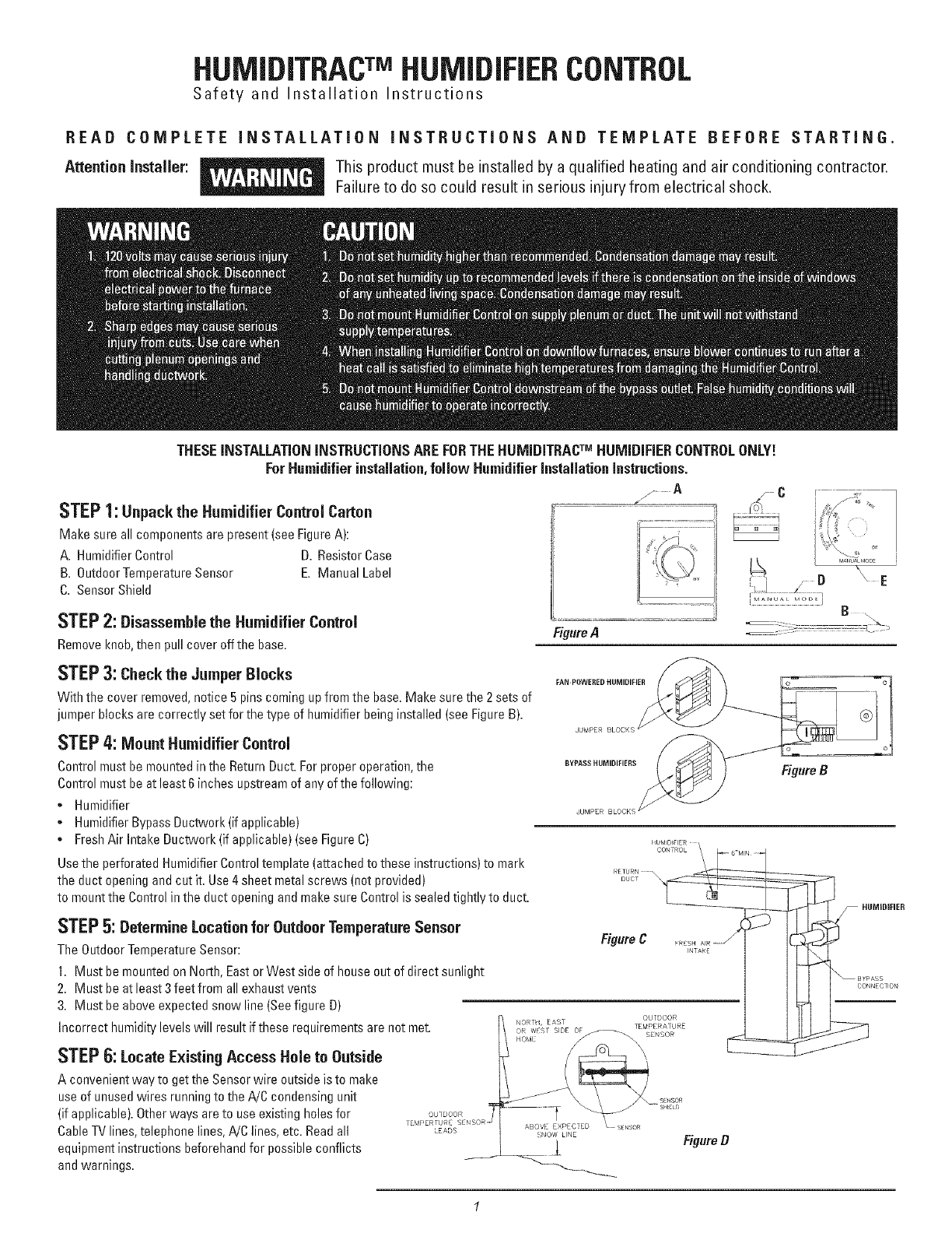
STEP1: Unpack the Humidifier Control Carton
Make sure all components are present (see FigureA):
A. HumidifierControl D. ResistorCase
B. OutdoorTemperature Sensor E. Manual Label
C. Sensor Shield
STEP2:Disassemble the Humidifier Control
Removeknob,then pull cover offthe base. FigureA
STEP3:Checkthe Jumper Blocks
With the cover removed,notice 5 pins coming upfrom the base. Make sure the 2 sets of
jumper blocks are correctly set for the type of humidifier being installed (see FigureB).
STEP4: MountHumidifier Control
FAN-POWERED HUMIDIFIER
3UMPER
Control must be mountedin the Return Duct.For properoperation, the
Controlmust be atleast 6 inches upstreamof any of the following:
* Humidifier
*HumidifierBypass Ductwork(if applicable)
* FreshAir Intake Ductwork (if applicable) (see Figure C)
BYPASS HUMIDIFIERS Figured
HDMDI I R
Usethe perforated HumidifierControl template (attachedto these instructions)to marl<
the duct opening and cut it. Use4 sheet metal screws (not provided)
to mountthe Control in the duct opening and make sure Control is sealed tightly to duct.
STEP 5: Determine Locationfor OutdoorTemperatureSensor
The OutdoorTemperatureSensor:
1. Must be mounted on North,Eastor West side of house out of direct sunlight
2. Must be at least3 feet from all exhaustvents
3. Must be aboveexpected snow line (Seefigure D)
Incorrect humiditylevels will result if these requirementsare not met.
STEP6: Locate Existing Access Hole to Outside
A convenientway to get the Sensorwire outside is to make
use of unusedwires running to the A!C condensing unit
(if applicable).Otherways are to useexisting holesfor
Cable11/lines, telephone lines,A/0 lines, etc. Readall 'EADD
equipment instructions beforehand for possible conflicts
and warnings.
NORH, EAS[
HOMI
ABOVE EXPECIED
SNOW LNE
L
OUTDOOR
TEMPERATURE
Figured
-- HUMiDiFiER
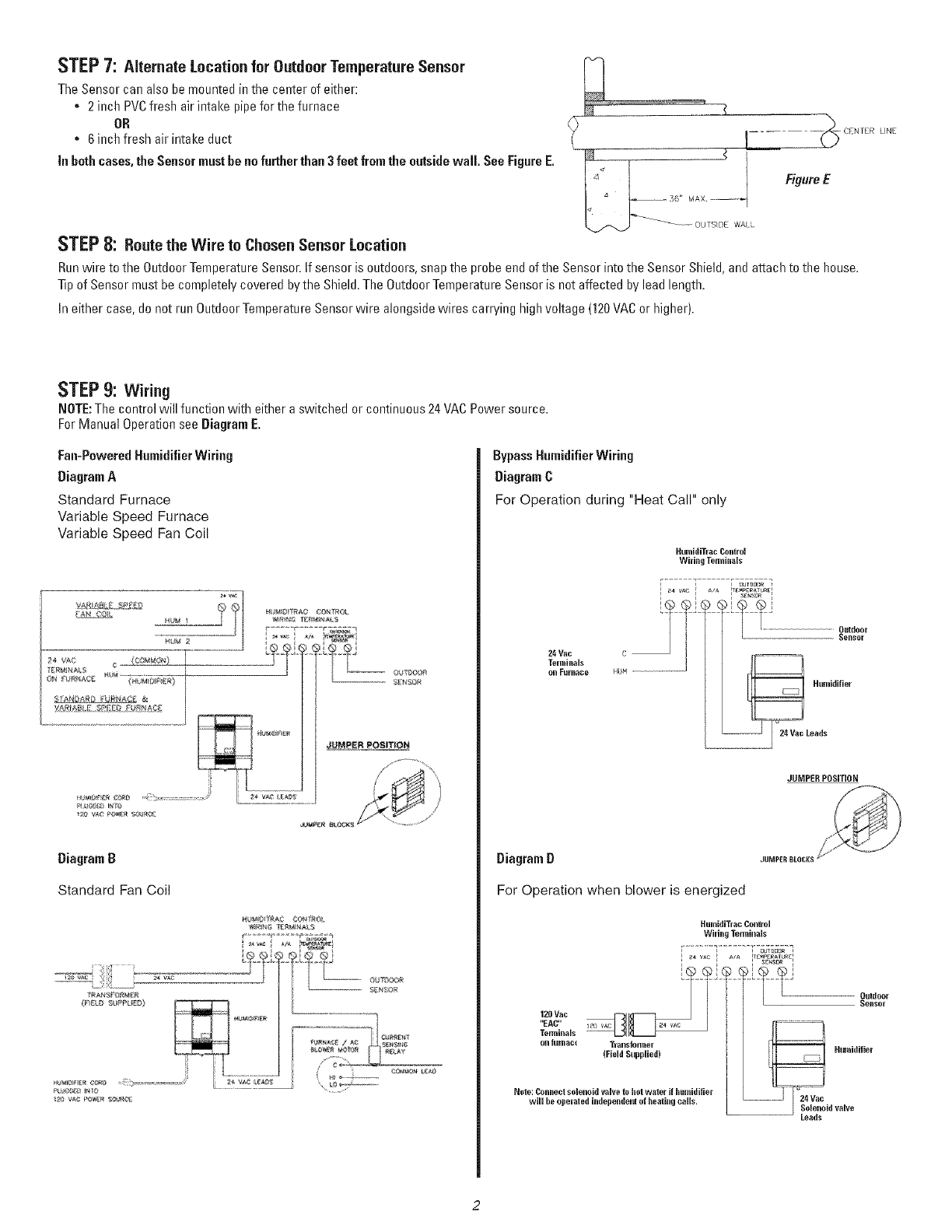
STEP7: Alternate Location for Outdoor Temperature Sensor
TheSensor can alsobe mountedin the center of either:
•2 inch PVCfresh air intake pipefor the furnace
OR
6 inch fresh air intake duct
in bethcases,the Sensormust be nofurther than3 feet fromthe outside wall. See FigureE,
STEP8: Routethe Wire to Chosen Sensor Location
CENrER LINE
Figure E
Runwire to the OutdoorTemperature Sensor.If sensor is outdoors, snap the probe end of the Sensor intothe SensorShield, and attachto the house.
Tipof Sensormust be completely covered by the Shield.The OutdoorTemperature Sensor is not affected by lead length.
In either case,do not run OutdoorTemperature Sensorwire alongsidewires carrying high voltage (120VACor higher).
STEP9: Wiring
NOTE:The control will function with either a switched or continuous 24 VACPower source.
ForManual OperationseeDiagram E.
Fan-PoweredHumidifierWiring
DiagramA
Standard Furnace
Variable Speed Furnace
Variable Speed Fan Ceil
DiagramD
Standard Fan Coil
HUM 8!Tf_AC CC_T_O_.
WIR N/_ _Z_]#tAL
Bypass Humidifier Wiring
DiagramC
For Operation during "Heat Call" only
24Vac C
Terminals
o1_Eurl_ace HUH .......
HumidiTlac Conlrol
Wiring Te.ninals
F7outdoor
Outdoor
Sel_Sllr
JUMPER POSiTiON
DiagramD
For Operation when blower is energized
120Vac
"EAC"
TerminMs --
o1_fLirllac_
HumidiTrac Control
Wiring Terminals
r
Transformer
(Field Supplied)
Nole: Conneclsolenoi(I valve to hol waler if hlllllilliRer
will be operated independelll of healing calls,
_Te_pEraTUR£_
Sensor
Humidifier
.............. 24Vac id valve
Leads

Installingthe HumidifierCobol forManualOperation
If itisnotfeasibleto usethe OutdoorTemperatureSensor,theHumidifierControlcanbe
installedinManualMode.
1. InserttheManualModeResistorCaseinto
theterminalslabeled "OutdoorTemperature
Sensor"onthehumidifierControl.
2. SnaptheResistorCaseintotheslot provided
so that ResistorCasesticksoutfromthe
bottomedgeefthe base.
3. Follow Instructons to complete the
wiring.Applythe ManualModeFaceplate
intothe recessedareaof thecover.Return
the coverto thebaseandre-install knob.
System Checkout
1. Forsystemtest, be sure that 24VACis appliedto the 24VAC
terminals of HumidifierControl.
2. Putthe cover and knob back onto HumidifierControl base.
3. Activate furnace blower andbesure thermostatis callingfor heat.
4. Rotatethe control knob of HumidifierControlclockwise to the
"Test" position.
5. If all isset up properly,you should be able to hearthe solenoid
valve click open. In "Test" mode,the Humidifierwill operatefor
1 minute.
6. If the humidifier does netactivate with the Humidifier Controlin
the "Test" position,refer to troubleshooting guide.
7. Settingthe HumidifierControl:
•If homeis occupied, set Humidifier Controlto "Normal"
•If homeis vacant, set HumidifierControlto "Off"
8. Inform homeownerto set the HumidifierControlto "Normal"
(position5) for the initial adjustmentperiod. Oncethe Humidifier
Controlis properlyadjusted, no further adjustmentis necessary!
HumidifierControl TroubleshootingGuide
SYMPTOM TROUBLESHOOTINGPROCEDURE
Humidifierdoes net
operate in "Test" mode
,Make sure furnace blower is operating and thermostat is calling for heat.
, Make sure the OutdoorTemperatureSensor is connected tothe "Outdoor Temperature Sensor" terminals of the control.
, Check mainwiring diagramfor correct Humidifier Controlinstallation.
, Check voltage at Humidifier Control24 VACterminals. Voltage should be 22VACminimum-30 VAC maximum.
•Check Humidifier Controlfor correct installation of jumper blocks.
•Check Current Sensing Relay(if used)for correct installation. Donot use Model 50Relayin transformer circuit or "24 VAC"
circuit of Humidifier Control.Model 50relay is to be usedin the "A/A" circuit only.
•In"Test" mode,humidifierwill operatefor 1 minuteonly. DONOTLEAVEIN TESTMODEAS HUMIDIFIERWILL NOTOPERATE.
3

Humidifieroperates only
in "Test" mode
• If outdoor temperature is greater than 65°For less than -32°F,the HumidifierControl will
only operate inthe "Test" mode.(Automatic Mode Only)
• If the humidity level inthe homeis higher than the knobsetting,the HumidifierControl
will notoperate the Humidifier.
• Check the resistance of the sensor by removingthe leads of the OutdoorTemperature
Sensorfromthe terminals and measuringthe resistance acrossthe wires with an ohmme-
ter. Confirm reading to outdoor temperature in Table 1.
• Make sure the OutdoorTemperatureSensoris mountedcompletely outside the house
on the North, East,or West side of the house and out of direct sunlight.
• If OutdoorTemperature Sensor is mounted infresh air intake duct, make sure the probe
is nofurther than 36inches from the outsidewall.
• Make sure the OutdoorTemperature Sensoris located at least3 feet away from all
exhaustvents.
TABLE 1
Outdoor
Temperature Resistance
100° F 6,000 OHMS
90° F 7,500 OHMS
80° F 9,500 OHMS
70° F 12,000OHMS
60° F 15,500OHMS
50° F 20,000OHMS
40° F 26,000OHMS
30° F 34,500OHMS
20° F 46,000OHMS
10° F 62,000OHMS
0° F 84,500OHMS
-10° F 116,500OHMS
-20° F 162,500OHMS
-30° F 229,500OHMS
HumidifierControl TroubleshootingGuide
SYMPTOM TROUBLESHOOTING PROCEDURE
Humidifieroperates • If the humidity levelin the homeis lessthan the knob setting,the HumidifierControlwill
constantly operate the Humidifier until the humidity level is higherthan the knob setting.
, In the "Test" mode,verify unit will operatefor approximatelyone minute.
, Check the resistance of the sensor by removingthe wires ofthe Outdoor Temperature
Sensor and measuringthe resistance acrossthe wires with an ohmmeter.Compare
measurementto outdoortemperature in Table 1.
• Make sure the OutdoorTemperatureSensor is mountedcompletely outside the houseon
the North, East,or West side of the house and out of direct sunlight..
, Rotatethe HumidifierControl knobcounterclockwise to the "Off" position, and observe
whether the humidifierturns off.If the humidifier still operates in the "Off" position,
performthe following:
1. Checksummary wiring diagramfor correct HumidifierControl Installation.
2. Removewires from Humidifier Control's"A/A" terminals. If Humidifier continues
to operate, replace solenoid valve.
Humidifieror Humidifier • Check for steady 22 VAC- 30VACwith voltmeter.
Control"chatters" or ,Make sure OutdoorTemperatureSensor wiring is not run alongsidewires carrying high voltage (120VACor higher).
clicks ONand OFFrapidly
WARNING
Sharp edgeson the opening may cause cuts. Use care when cutting the plenum opening
and installing the Humidifier Control.
CAUTION
• Do not mount Humidifier Control on supply plenum or duct. Tile unitwill =rotwithstand
supplytemperatures and will malfunction!
• When installing Humidifier Control on counterflow furnaces, ensure blower continues
to run after a heat call issatisfied to eliminate hightemperatures from damaging the
Humidifier Control.
• Donot mount Humidifier Control downstream of the bypassoutlet. FalsehumiditV
conditions will cause humidifier to operate incorrectly.
1. CUTOUTTEMPLATEALONGEDGES.
2. PLACETHiSTEMPLATEONTHERETURNPLENUMUPSTREAMOF(BEFORE)THE
HUMiDiFiERCONNECTION.
3. TRACETHE OUTSIDEEDGESOFTHiSTEMPLATE.
4. REMOVETEMPLATEAND ACCURATELYCUTTHEPLENUMOPENING.
5. USING4 SHEETMETALSCREWS,iNSTALLHUMiDiFiERCONTROLiN PLENUMOPENING.
4
Form:AG - UAWC- 02
Catalog:63UA- WCI
© 2003CAC/BDP
7310W. Morris St.
Indianapolis,IN 46231
DP #10005688
B2202881A
Rev.10-28-03
