CARRIER Package Units(both Units Combined) Manual L0901375
User Manual: CARRIER CARRIER Package Units(both units combined) Manual CARRIER Package Units(both units combined) Owner's Manual, CARRIER Package Units(both units combined) installation guides
Open the PDF directly: View PDF ![]() .
.
Page Count: 178 [warning: Documents this large are best viewed by clicking the View PDF Link!]
WEATHERMAKER ®
48/50AJ,AK,AW, AY,A2,A3,A4,A5020-060
Single Package Large Rooftop Units
with COMFORTLINK Ti Version 5.x Controls
Controls, Start-Up, Operation,
Service and Troubleshooting
CONTENTS
Page
SAFETY CONSiDERATiONS ......................... 2
GENERAL ......................................... 2,3
Conventions Used in this Manual .................... 3
BASIC CONTROL USAGE .......................... 3-6
ComfortLink Controls ............................... 3
Scrolling Marquee ................................... 4
Accessory Navigator TM Display ...................... 4
Operation ............................................ 4
System PilotTM Interface ............................. 5
CON Tables and Display ............................. 5
• GENERICS STATUS DISPLAY TABLE
START-UP ........................................ 7-27
Unit Preparation ..................................... 7
Unit Setup ........................................... 7
Internal Wiring ....................................... 7
Accessory Installation ............................... 7
Crankcase Heaters .................................. 7
Evaporator Fan ...................................... 7
Controls ............................................. 7
Gas Heat ............................................ 7
CONTROLS QUICK START ...................... 27-29
Two-Stage Constant Volume Units with
Mechanical Thermostat .......................... 27
Two-Stage Constant Volume Units with
Space Sensor .................................... 27
Variable Air Volume Units Using Return Air Sensor
or Space Temperature Sensor .................... 28
Multi-Stage Constant Volume Units with
Mechanical Thermostat .......................... 28
Multi-Stage Constant Volume Units with
Space Sensor .................................... 28
Economizer Options ................................ 28
Indoor Air Quality Options .......................... 29
Exhaust Options .................................... 29
Programming Operating Schedules ................ 29
SERVICE TEST .................................. 29,30
General ............................................. 29
Service Test Mode Logic ........................... 29
Independent Outputs ............................... 30
Fans in Service Test Mode ......................... 30
Cooling in Service Test Mode ....................... 30
Heating in Service Test Mode ....................... 30
THIRD PARTY CONTROL ........................ 3L32
Thermostat ......................................... 3]
Alarm Output ....................................... 3]
Remote Switch ..................................... 3!
VFD Control ........................................ 3]
Supply Air Reset ................................... 3]
Demand Limit Control .............................. 3]
Demand Controlled Ventilation Control ............. 3!
CONTROLS OPERATION ........................ 32-75
Modes .............................................. 32
• SYSTEM MODES
• HVAC MODES
Page
Unit Configuration Submenu ....................... 35
Cooling Control .................................... 37
• SETTING UP THE SYSTEM
• MACHINE DEPENDENT CONFIGURATIONS
• SET POINTS
• SUPPLY AIR RESET CONFIGURATION
• COOLING CONFIGURATION
• COMPRESSOR SAFETIES
• COMPRESSOR TIME GUARDS
• COOL MODE SELECTION PROCESS
• COOLING MODE DIAGNOSTIC HELP
• SUMZ COOLING ALGORITHM
• DEMAND LIMIT CONTROL
• HEAD PRESSURE CONTROL
• ECONOMIZER INTEGRATION WITH
MECHANICAL COOLING
Heating Control .................................... 5O
• SETTING UP THE SYSTEM
• HEAT MODE SELECTION PROCESS
• TEMPERATURE DRIVEN HEAT MODE
EVALUATION
• HEAT MODE DIAGNOSTIC HELP
• INTEGRATED GAS CONTROL BOARD LOGIC
• RELOCATE SAT SENSOR FOR HEATING IN
LINKAGE SYSTEMS
• MORNING WARM UP
• TEMPERING MODE
Static Pressure Control ............................ 57
• OPERATION
• SETTING UP THE SYSTEM
• STATIC PRESSURE RESET OPERATION
• RELATED POINTS
Fan Status Monitoring .............................. 59
• GENERAL
• SETTING UP THE SYSTEM
• SUPPLY FAN STATUS MONITORING LOGIC
Dirty Filter Switch .................................. 60
Economizer ........................................ 60
• SETTING UP THE SYSTEM
• ECONOMIZER OPERATION
• UNOCCUPIED ECONOMIZER FREE COOLING
• ECONOMIZER OPERATION CONFIGURATION
• ECONOMIZER DIAGNOSTIC HELP
Building Pressure Control .......................... 63
• BUILDING PRESSURE CONFIGURATION
• CONSTANT VOLUME 2-STAGE CONTROL
OPERATION
• MULTIPLE POWER EXHAUST STAGE BUILDING
PRESSURE CONTROL OPERATION
• VFD POWER EXHAUST BUILDING PRESSURE
CONTROL
Smoke Control Modes .............................. 66
• FIRE-SMOKE INPUTS
• AIRFLOW CONTROL DURING THE
FIRE-SMOKE MODES
• RELEVANT ITEMS
Manufacturer reserves the right to discontinue, or change at any time, specifications or designs without notice and without incurring obligations.
Catalog No. 04-53480050-01 Printed in U.S.A. Form 48/5OA-7T Pg 1 5-08 Replaces: 48/50A-6T
CONTENTS (cont)
Page
Indoor Air Quality Control .......................... 67
• OPERATION
• SETTINGUP THE SYSTEM
• PRE-OCCUPANCY PURGE
Dehumidification and Reheat ...................... 69
• SETTINGUP THE SYSTEM
• OPERATION
Temperature Compensated Start ................... 71
• SETTINGUP THE SYSTEM
• TEMPERATURE COMPENSATED START LOGIC
Carrier Comfort Network ®(CCN) System ........... 71
Alert Limit Configuration ........................... 72
Sensor Trim Configuration ......................... 73
Discrete Switch Logic Configuration ............... 74
Display Configuration .............................. 74
Remote Control Switch Input....................... 74
Hot Gas Bypass .................................... 75
Space Temperature Offset ......................... 75
TIME CLOCK CONFIGURATION ................. 75-77
TROUBLESHOOTING .......................... 77-i01
Complete Unit Stoppage ........................... 77
Single Circuit Stoppage ............................ 77
Service Analysis ................................... 77
Restart Procedure ................................. 77
Thermistor Troubleshooting ....................... 77
Transducer Troubleshooting ....................... 78
Forcing Inputs and Outputs ........................ 90
Run Status Menu ................................... 90
• AUTO VIEW OF RUN STATUS
• ECONOMIZER RUN STATUS
• COOLING INFORMATION
• MODE TRIP HELPER
• CCN/LINKAGE DISPLAY TABLE
• COMPRESSOR RUN HOURS DISPLAY TABLE
• COMPRESSOR STARTS DISPLAY TABLE
• TIME GUARD DISPLAY TABLE
• SOFTWARE VERSION NUMBERS DISPLAY TABLE
Alarms and Alerts .................................. 93
MAJOR SYSTEM COMPONENTS .............. 101-127
General ........................................... 101
Factory-Installed Components .................... 101
Accessory Control Components .................. 124
SERVICE ...................................... 128-139
Service Access ................................... 128
Cleaning .......................................... 128
Lubrication ....................................... 130
Evaporator Fan Performance Adjustment ......... 130
Evaporator Fan Coupling Assembly ............... 130
Evaporator Fan Service and Replacement ........ 131
Belt Tension Adjustment .......................... 131
Evaporator-Fan Motor Replacement ............... 131
Condenser-Fan Adjustment ....................... 132
Four-Inch Filter Replacement ..................... 132
Power Failure ..................................... 132
Refrigerant Charge ................................ 132
Thermostatic Expansion Valve (TXV) .............. 132
Gas Valve Adjustment ............................ 132
Main Burners ..................................... 139
Filter Drier ........................................ 139
Replacement Parts ................................ 139
APPENDIX A -- LOCAL DISPLAY TABLES .... 140-147
APPENDIX B -- CCN TABLES ................. 148-160
APPENDIX C -- VFD INFORMATION ........... 161-169
APPENDIX D -- MODE SELECTION
PROCESS ....................................... 170
INDEX ............................................. 171
CONTROLS SET POINT AND
CONFIGURATION LOG .................. CL-1 to CL-5
UNIT START-UP CHECKLIST ..................... CL-6
SAFETY CONSIDERATIONS
Installation and servicing of air-conditioning equipment can
be hazardous due to system pressure and electrical compo-
nents. Only trained and qualified service personnel should in-
stall, repair, or service air-conditioning equipment. Untrained
personnel can perform the basic maintenance functions of re-
placing filters. Trained service personnel should perform all
other operations.
When working on air-conditioning equipment, observe pre-
cautions in the literature, tags and labels attached to the unit,
and other safety precautions that may apply. Follow all safety
codes. Wear safety glasses and work gloves. Use quenching
cloth for unbrazing operations. Have fire extinguishers avail-
able for all brazing operations.
Before performing service or maintenance operation on
unit turn off and lock off main power switch to unit.
Electrical shock can cause personal injury and death.
Shut off all power to this equipment during installation
and service. The unit may have an internal non-fused
disconnect or a field-installed disconnect. Note that the
unit may also be equipped with a convenience outlet,
that this outlet is wired to the line side of the unit-
mounted disconnect and will remain hot when the
disconnect in the unit is off. There is a separate fuse/
disconnect for the convenience outlet.
Puron (R-410A) refrigerant systems operate at higher pres-
sures than standard R-22 systems. Do not use R-22 service
equipment or components on Puron refrigerant equipment.
If service equipment is not rated for Puron refrigerant,
equipment damage or personal injury may result.
This unit uses a lnicroprocesso>based electronic control
system. Do not use jumpers or other tools to short out com-
ponents or to bypass or otherwise depart from recom-
mended procedures. Any short-to-ground of the control
board or accompanying wiring may destroy the electronic
modules or electrical components.
1. Improper installation, adjustlnent, alteration, service,
or maintenance can cause property damage, personal
injury, or loss of life. Refer to the User's Inforlnation
Manual provided with this unit for more details.
2. Do not store or use gasoline or other flalmnable va-
pors and liquids in the vicinity of this or any other
appliance.
What to do it'you smell gas:
1. DO NOT try to light any appliance.
2. DO NOT touch any electrical switch, or use any phone
in your building.
3. IMMEDIATELY call your gas supplier from a neigh-
bor's phone. Follow the gas supplier's instructions.
4. If you cannot reach your gas supplier call the fire
department.
GENERAL
This book contains Start-Up, Controls Operation, Trouble-
shooting and Service information for the 48/50A Series
rooftop units. See Table 1. These units are equipped with
(_nfortLink TM controls.
Use this guide in conjunction with the separate installation
instructions packaged with the unit. Refer to the Wiring Dia-
grains literature for more detailed wiring information.
Table 1 -- A Series Product Line
UNIT
48AJ
48AK
48AW
48AY
48A2
48A3
48A4
48A5
50AJ
50AK
50AW
50AY
50A2
50A3
50A4
50A5
CV --
MCHX --
VAV --
APPLICATION
CV Unit with Gas Heat, Vertical Supply
VAV Units with Gas Heat, Vertical Supply
CV Unit with Gas Heat, Horizontal Supply
VAV Unit with Gas Heat, Horizontal Supply
CV Unit with Gas Heat, Vertical Supply with MCHX Coil
VAV Unit with Gas Heat, Vertical Supply with MCHX Coil
CV Unit with Gas Heat, Horizontal Supply with MCHX Coil
VAV Unit with Gas Heat, Horizontal Supply with MCHX Coil
CV Unit with Optional Electric Heat, Vertical Supply
VAV Unit with Optional Electric Heat, Vertical Supply
CV Unit with Optional Electric Heat, Horizontal Supply
VAV Unit with Optional Electric Heat, Horizontal Supply
CV Unit with Optional Electric Heat, Vertical Supply with MCHX
Coil
VAV Unit with Optional Electric Heat, Vertical Supply with MCHX
Coil
CV Unit with Optional Electric Heat, Horizontal Supply with
MCHX Coil
VAV Unit with Optional Electric Heat, Horizontal Supply with
MCHX Coil
LEGEND
Constant Volume
Microchannel Heat Exchanger
Variable Air Volume
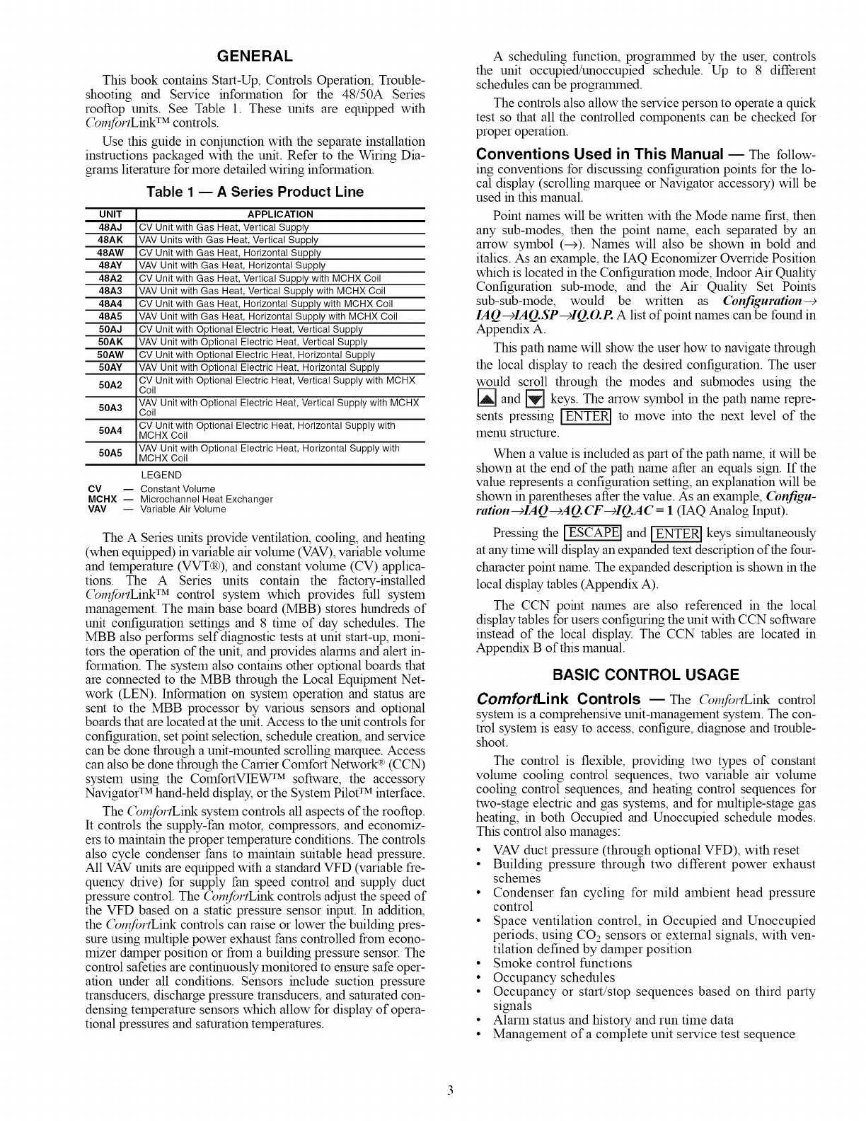
The A Series units provide ventilation, cooling, and heating
(when equipped) in variable air volume (VAV), variable volume
and temperature (VVT(R)), and constant volume (CV) applica-
tions. The A Series units contain the factory-installed
(_mfortLink TM control system which provides full system
management. The main base board (MBB) stores hundreds of
unit configuration settings and 8 time of day schedules. The
MBB also performs self diagnostic tests at unit start-up, moni-
tors the operation of the unit, and provides alarms and alert in-
formation. The system also contains other optional boards that
are connected to the MBB through the Local Equipment Net-
work (LEN). Information on system operation and stares are
sent to the MBB processor by various sensors and optional
boards that are located at the unit. Access to the unit controls for
configuration, set point selection, schedule creation, and service
can be done through a unit-mounted scrolling marquee. Access
can also be done through the Carrier Comfort Network R>(CCN)
system using the ComfortVIEW rM software, the accessory
Navigator TM hand-held display, or the System Pilot TM interface.
The (_nfortLink system controls all aspects of the rooftop.
It controls the supply-fan motor, compressors, and economiz-
ers to maintain the proper temperature conditions. The controls
also cycle condenser fans to maintain suitable head pressure.
All VAV units are equipped with a standard VFD (variable fre-
quency drive) for supply fan speed control and supply duct
pressure control. The (_mfortLink controls adjust the speed of
the VFD based on a static pressure sensor input. In addition,
the (_mfortLink controls can raise or lower the building pres-
sure using multiple power exhaust fans controlled from econo-
mizer damper position or from a building pressure sensor. The
control safeties are continuously monitored to ensure safe oper-
ation under all conditions. Sensors include suction pressure
transducers, discharge pressure transducers, and saturated con-
densing temperature sensors which allow for display of opera-
tional pressures and saturation temperatures.
A scheduling function, prograimned by the user, controls
the unit occupied/unoccupied schedule. Up to 8 different
schedules can be progralmned.
The controls also allow the service person to operate a quick
test so that all the controlled components can be checked for
proper operation.
Conventions Used in This Manual EThe follow-
ing conventions for discussing configuration points for the lo-
cal display (scrolling marquee or Navigator accessory) will be
used in this manual.
Point names will be written with the Mode name first, then
any sub-modes, then the point name, each separated by an
arrow symbol (--->). Names will also be shown in bold and
italics. As an example, the IAQ Economizer Ovemde Position
which is located in the Configuration mode, Indoor Air Quality
Configuration sub-mode, and the Air Quality Set Points
sub-sub-mode, would be written as (bnfiguration--€
IAQ---_IAQ.SP-_IQ.O.P. A list of point names can be found in
Appendix A.
This path name will show the user how to navigate through
the local display to reach the desired configuration. The user
would scroll through the modes and submodes using the
[] and _--] keys. The arrow symbol in the path name repre-
sents pressing _ to move into the next level of the
menu structure.
When a value is included as part of the path name, it will be
shown at the end of the path name after an equals sign. If the
value represents a configuration setting, an explanation will be
shown in parentheses after the value. As an example, Configu-
ration--+IAQ---)AQ. CF--+IQ.AC =1(IAQ Analog Input).
Pressing the _ and _ keys simultaneously
at any thne will display an expanded text description of the four-
character point name. The expanded description is shown in the
local display tables (Appendix A).
The CCN point names are also referenced in the local
display tables for users configuring the unit with CCN software
instead of the local display. The CCN tables are located in
Appendix B of this manual.
BASIC CONTROL USAGE
ComfortLink Controls EThe (_mfortLink control
system is a comprehensive unit-management system. The con-
trol system is easy to access, configure, diagnose and trouble-
shoot.
The control is flexible, providing two types of constant
volume cooling control sequences, two variable air volume
cooling control sequences, and heating control sequences for
two-stage electric and gas systems, and for multiple-stage gas
heating, in both Occupied and Unoccupied schedule modes.
This control also manages:
• VAV duct pressure (through optional VFD), with reset
• Building pressure through two different power exhaust
schemes
• Condenser fan cycling for mild ambient head pressure
control
• Space ventilation control, in Occupied and Unoccupied
periods, using CO2 sensors or external signals, with ven-
tilation defined by damper position
• Smoke control functions
• Occupancy schedules
• Occupancy or start/stop sequences based on third party
signals
• Alarm status and history and run time data
• Management of a complete unit service test sequence
Systemdiagnosticsareenhancedbytheuseof multiple
externalsensorsforairtemperatures,airpressures,refrigerant
temperatures,andrefrigerantpressures.Unit-mountedactua-
torsprovidedigitalfeedbackdatatotheunitcontrol.
The(_l_fortLinkcontrolsystemis fullyCOlrununicating
andcable-readyforconnectiontotheCarrierComfortNetwork
(CCN)buildingmanagementsystem.Thecontrolprovides
high-speedcolmnunicationsfor remotemonitoringviathe
Internet.Multipleunitscanbelinkedtogether(andtoother
(_l_fortLinkcontrolequippedunits)usinga3-wirecolmnuni-
cationbus.
The(_n?fortLinkcontrolsystemiseasytoaccessthrough
theuseofaunit-mounteddisplaymodule.Thereisnoneedto
bringaseparatecomputertothisunitforstart-up.Accessto
controlmenusisshnplifiedbytheabilitytoquicklyselectfrom
11menus.A scrollingreadoutprovidesdetailedexplanations
ofcontrolreformation.Onlyfour,large,easy-to-usebuttonsare
requiredtomaneuverthroughtheentirecontrolsmenu.
For addedserviceflexibility,an accessoryhand-held
Navigatormoduleisalsoavailable.Thisportabledevicehasan
extendedcolmnunicationcablethatcanbepluggedintothe
unit'scolmnunicationnetworkeitheratthemarecontrolboxor
atthe opposite end of the unit, at a remote modular plug. The
Navigator display provides the same menu structure, control
access and display data as is available at the unit-mounted
scrolling marquee display.
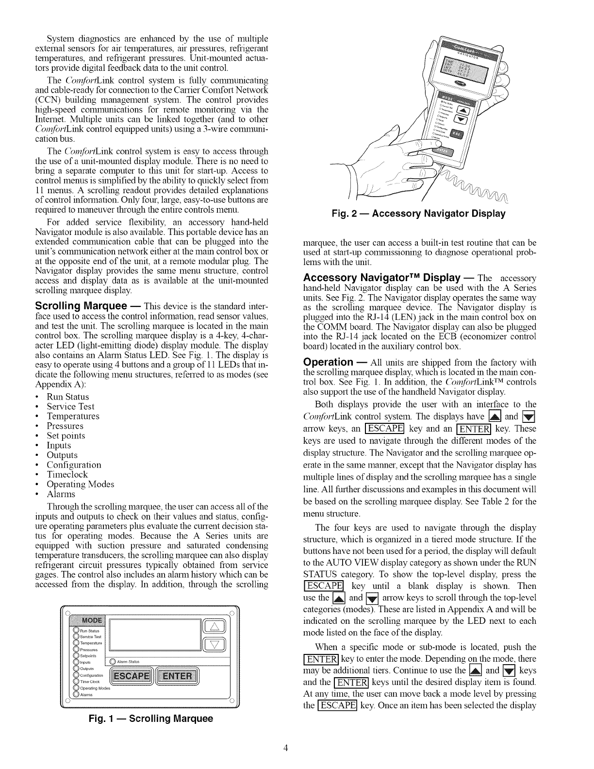
Scrolling Marquee -- This device is the standard inter-
face used to access the control information, read sensor values,
and test the unit. The scrolling marquee is located in the main
control box. The scrolling marquee display is a 4-key, 4-char-
acter LED (light-emitting diode) display module. The display
also contains an Alarm Stares LED. See Fig. 1. The display is
easy to operate using 4 buttons and a group of 11 LEDs that in-
dicate the following menu structures, referred to as modes (see
Appendix A):
•Run Status
• Service Test
• Temperatures
• Pressures
• Set points
• Inputs
• Outputs
• Configuration
• Timeclock
• Operating Modes
• Alarms
Through the scrolling marquee, the user can access all of the
inputs and outputs to check on their values and status, config-
ure operating parameters plus evaluate the current decision sta-
res for operating modes. Because the A Series units are
equipped with suction pressure and saturated condensing
temperature transducers, the scrolling marquee can also display
refrigerant circuit pressures typically obtained from service
gages. The control also includes an alarm history which can be
accessed from the display. In addition, through the scrolling
O Alarms ©_
Fig. 1 -- Scrolling Marquee
Fig. 2 -- Accessory Navigator Display
marquee, the user can access a built-in test routine that can be
used at start-up colrunissioning to diagnose operational prob-
lems with the unit.
Accessory Navigator TM Display-- The accessory
hand-held Navigator display can be used with the A Series
units. See Fig. 2. The Navigator display operates the same way
as the scrolling marquee device. The Navigator display is
plugged into the RJ-14 (LEN) jack in the main control box on
the COMM board. The Navigator display can also be plugged
into the RJ-14 jack located on the ECB (economizer control
board) located in the auxiliary control box.
Operation -- All units are shipped from the factory with
the scrolling marquee display, which is located in the mare con-
trol box. See Fig. 1. In addition, the (_n?fortLink TM controls
also support the use of the handheld Navigator display.
Both displays provide the user with an interface to the
(_n_fortLink control system. The displays have [] and []
arrow keys, an IESCAPEI key and an _ key. These
keys are used to navigate through the different modes of the
display structure. The Navigator and the scrolling marquee op-
erate in the same manner, except that the Navigator display has
multiple lines of display and the scrolling marquee has a single
line. All further discussions and examples in this document will
be based on the scrolling marquee display. See Table 2 for the
menu structure.
The four keys are used to navigate through the display
structure, which is organized in a tiered mode structure. If the
buttons have not been used for a period, the display will default
to the AUTO VIEW display category as shown under the RUN
STATUS category. To show the top-level display, press the
]ESCAPE] key until a blank display is shown. Then
use the [_ and [] arrow keys to scroll through the top-level
categories (modes). These are listed in Appendix A and will be
indicated on the scrolling marquee by the LED next to each
mode listed on the face of the display.
When a specific mode or sub-mode is located, push the
key to enter the mode. Depending on the mode, there
may be additional tiers. Continue to use the _ and _ keys
and the _ keys until the desired display item is found.
At any time, the user can move back a mode level by pressing
the ]ESCAPE] key. Once an item has been selected the display
f "-,
will flash showing the item, followed by the item value and
then followed by the item units (if any).
Items in the Configuration and Service Test modes are
password protected. The display will flash PASS and WORD
when required. Use the _ and arrow keys to enter the
four digits of the password. The default password is 1111.
Pressing the IESCAPEI and _ keys simultaneously
will scroll an expanded text description across the display indi-
cating the full meaning of each display point. Pressing the
IESCAPEI and _ keys when the display is blank
(MODE LED level) will return the display to its default menu
of rotating AUTO VIEW display items. In addition, the pass-
word will need to be entered again before changes can be made.
Changing item values or testing outputs is accomplished in
the same manner. Locate and display the desired item. If the
display is in rotating auto-view, press the _ key to stop
the display at the desired item. Press the _ key again so
that the item value flashes. Use the arrow keys to change the
value of state of an item and press the _ key to accept
it. Press the ]ESCAPE] key and the item, value or units display
will resume. Repeat the process as required for other items.
If the user needs to force a variable, follow the same process
as when editing a configuration parameter. A forced variable
will be displayed with a blinking "f' following its value. For
example, if supply fan requested (FAN.F) is forced, the display
shows "YESf', where the "f' is blinking to signify a force on
the point. Remove the force by selecting the point that is forced
with the _ key and then pressing the [_ and [_ ar-
row keys simultaneously.
Depending on the unit model, factory-installed options and
field-installed accessories, some of the items in the various
Mode categories may not apply.
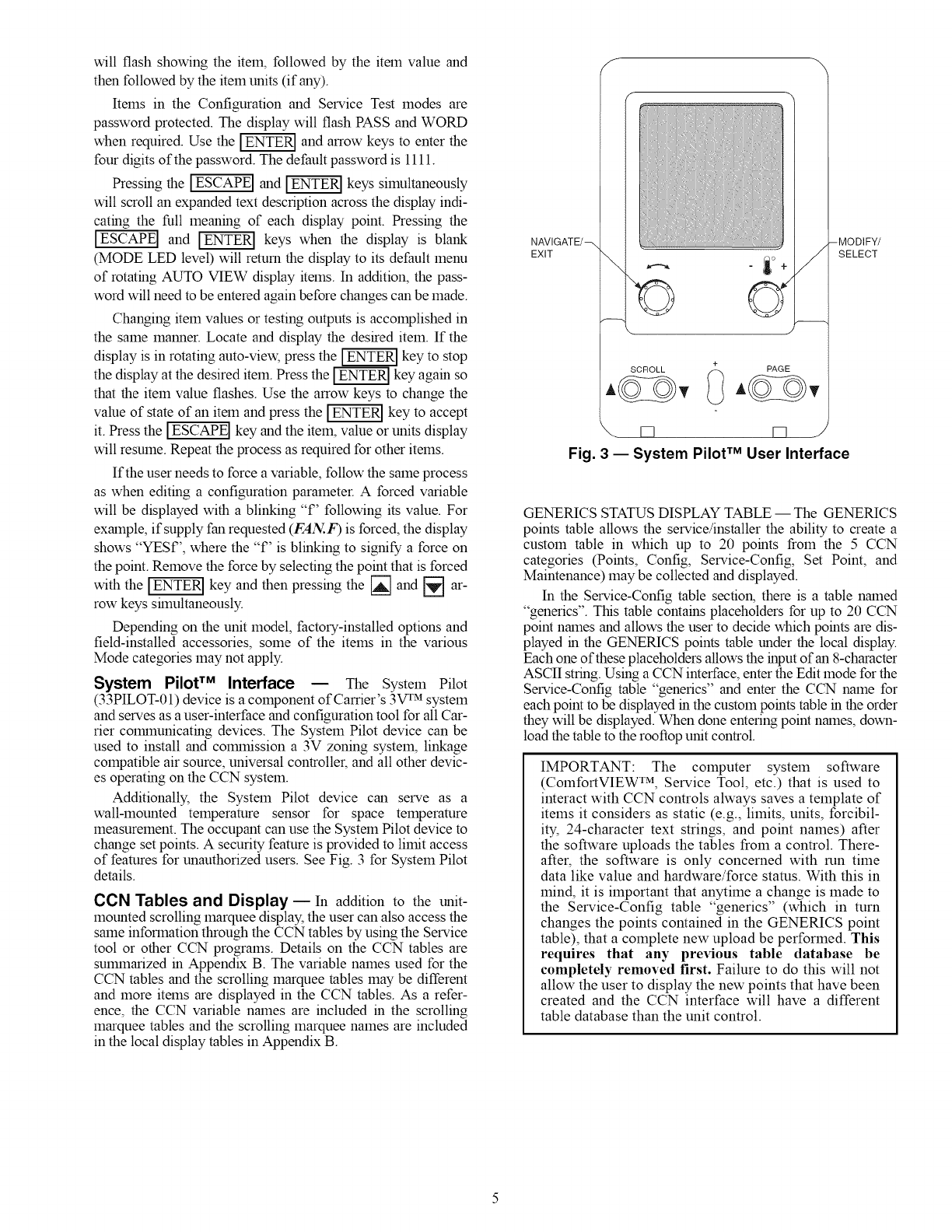
System PilotTM Interface E The System Pilot
(33PILOT-01) device is a component of Carrier's 3V rM system
and serves as a user-interface and configuration tool for all Car-
rier COlrnnunicating devices. The System Pilot device can be
used to install and COlmnission a 3V zoning system, linkage
compatible air source, universal controller, and all other devic-
es operating on the CCN system.
Additionally, the System Pilot device can serve as a
wall-lnounted telnperamre sensor for space telnperamre
measurement. The occupant can use the System Pilot device to
change set points. A security feature is provided to limit access
of features for unauthorized users. See Fig. 3 for System Pilot
details.
CCN Tables and Display E In addition to the unit-
mounted scrolling marquee display, the user can also access the
same inforlnation through the CCN tables by using the Service
tool or other CCN programs. Details on the CCN tables are
SUlnmarized in Appendix B. The variable names used for the
CCN tables and the scrolling marquee tables may be different
and more items are displayed in the CCN tables. As a refer-
ence, the CCN variable names are included in the scrolling
marquee tables and the scrolling marquee names are included
in the local display tables in Appendix B.
NAVIGATE/_
EXIT \"!? o
\ J
/
SCROLL _ PAGE
-MODIFY/
SELECT
Fig. 3 -- System Pilot TM User Interface
GENERICS STATUS DISPLAY TABLE -- The GENERICS
points table allows the service/installer the ability to create a
custom table in which up to 20 points from the 5 CCN
categories (Points, Config, Service-Config, Set Point, and
Maintenance) may be collected and displayed.
In the Service-Config table section, there is a table named
"generics". This table contains placeholders for up to 20 CCN
point names and allows the user to decide which points are dis-
played in the GENERICS points table under the local display.
Each one of these placeholders allows the input of an 8-character
ASCII string. Using a CCN interface, enter the Edit mode for the
Service-Config table "generics" and enter the CCN name for
each point to be displayed in the custom points table in the order
they will be displayed. When done entering point names, down-
load the table to the rooftop unit control.
IMPORTANT: The computer system software
(ColnfortVIEW TM, Service Tool, etc.) that is used to
interact with CCN controls always saves a template of
items it considers as static (e.g., limits, units, forcibil-
ity, 24-character text strings, and point names) after
the software uploads the tables from a control. There-
after, the software is only concerned with run time
data like value and hardware/force stares. With this in
mind, it is important that anytime a change is made to
the Service-Config table "generics" (which in turn
changes the points contained in the GENERICS point
table), that a complete new upload be performed. This
requires that any prex4ous table database be
completely removed first. Failure to do this will not
allow the user to display the new points that have been
created and the CCN interface will have a different
table database than the unit control.
RUN
STATUS
Auto View of
Run Status
(VIEW)
$
Econ
Run Status
(ECON)
$
Cooling
Information
(COOL)
$
Mode
Trip Helper
(TRIP)
$
CCN
Linkage
(LINK)
$
Compressor
Run Hours
(HRS)
$
Compressor
Starts
(STRT)
$
Timeguards
(TMGD)
4.
Software
Version
Numbers
(VERS)
SERVICE
TEST
Service Test Mode
(TEST)
4.
Software
Command
Disable
(STOP)
4.
Soft Stop
Request
(S.STP)
4.
Supply Fan
Request
(FAN.F)
4.
4 in. Filter
Change Mode
(F.4.CH)
4.
Test Independent
Outputs
(INDP)
4.
Test Fans
(FANS)
4.
Test Cooling
(COOL)
4.
Test Heating
(HEAT)
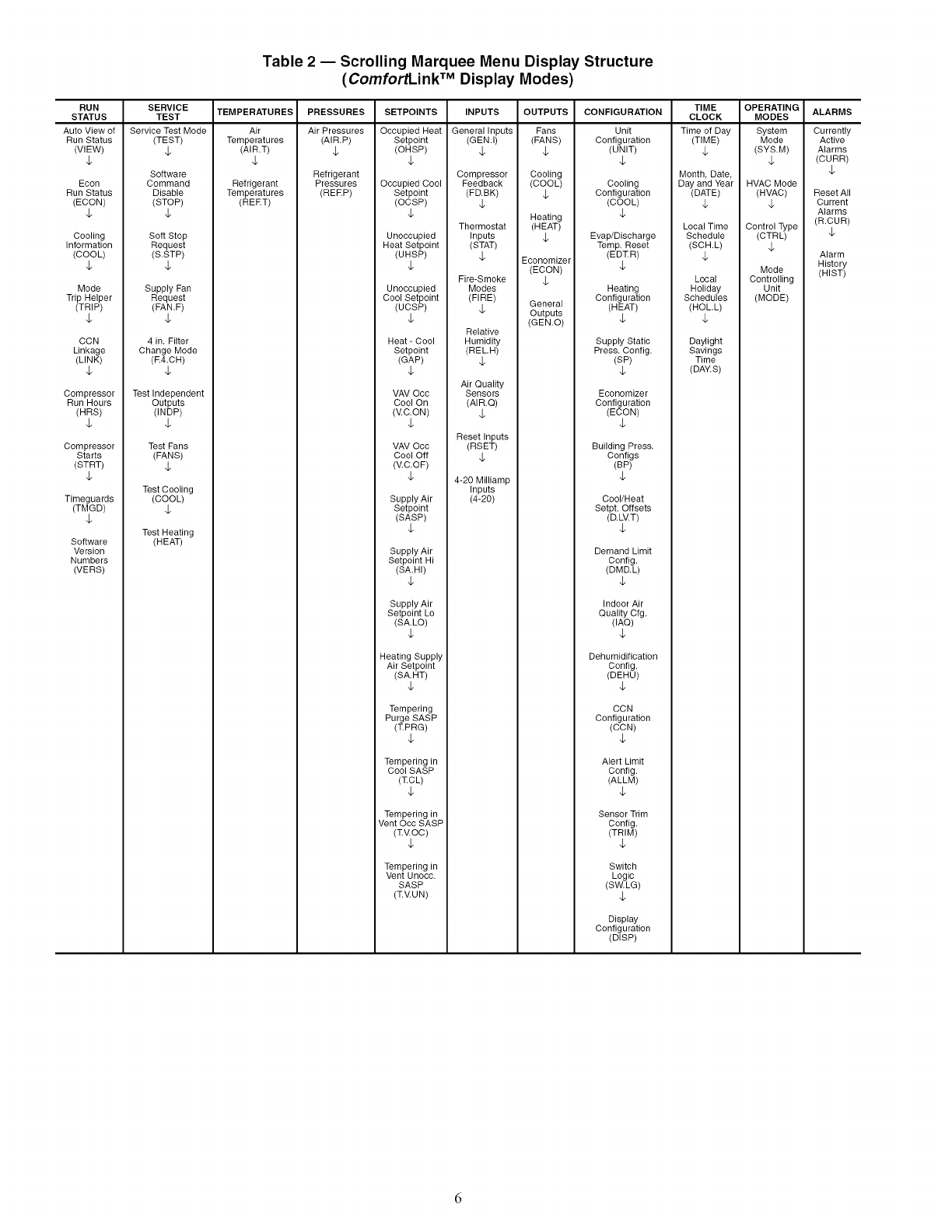
Table 2-- Scrolling Marquee Menu Display Structure
(ComfortLink TM Display Modes)
TEMPERATURES
Air
Temperatures
(AIR.T)
4.
Refrigerant
Temperatures
(REET)
PRESSURES
Air Pressures
(AIR.P)
4.
Refrigerant
Pressures
(REEP)
SETPOINTS
Occupied Heat
Setpoint
(OHSP)
4.
Occupied Cool
Setpoint
(OCSP)
4.
Unoccupied
Heat Setpoint
(UHSP)
4.
Unoccupied
Cool Setpoint
(UCSP)
4.
Heat - Cool
Setpoint
(GAP)
4.
VAV Occ
Cool On
(V.C.ON)
4.
VAV Occ
Cool Off
(V.C.OF)
4.
Supply Air
Setpoint
(SASP)
4.
Supply Air
Setpoint Hi
(SA.HI)
4.
Supply Air
Setpoint Lo
(SA.LO)
4.
Heating Supply
Air Setpoint
(SA.HT)
4.
Tempering
Purge SASP
(TPRG)
4.
Tempering in
Cool SASP
(TCL)
4.
Tempering in
Vent Occ SASP
(TV.OC)
4.
Tempering in
Vent Unocc.
SASP
(T.V.UN)
INPUTS OUTPUTS CONFIGURATION
General Inputs Fans Unit
(GEM.I) (FANS) Configuration
4. 4. (UNIT)
4.
Compressor Cooling
Feedback (COOL) Cooling
(FD.BK) 4. Configuration
4. (COOL)
Heating 4.
Thermostat (HEAT)
Inputs 4. Evap/Discharge
(STAT) Temp. Reset
4. Economizer (EDT.R)
(ECON) 4.
Fire-Smoke 4.
Modes Heating
(FIRE) General Configuration
4. Outputs (HEAT)
(GEM.O) 4.
Relative
Humidity Supply Static
(RELH) Press. Config.
4. (SP)
4.
Air Quality
Sensors Economizer
(AIR.Q) Configuration
4. (ECON)
4.
Reset Inputs
(RSET) Building Press
4. Configs
(BP)
4-20 Milliamp 4.
Inputs
(4-20) Cool/Heat
Setpt. Offsets
(D.LV.T)
4.
Demand Limit
Config.
(DMD.L)
4.
Indoor Air
Quality Cfg.
(IAQ)
4.
Dehumidification
Config.
(DEHU)
4.
CCN
Configuration
(CCN)
4.
Alert Limit
Config.
(ALLM)
4.
Sensor Trim
Config.
(TRIM)
4.
Switch
Logic
(SW.LG)
4.
Display
Configuration
(DISP)
TIME
CLOCK
Time of Day
(TIME)
4.
Month, Date,
Day and Year
(DATE)
4.
Local Time
Schedule
(SCH.L)
4.
Local
Holiday
Schedules
(HOLL)
4.
Daylight
Savings
Time
(DAWS)
OPERATING
MODES
System
Mode
(SYS.M)
4.
HVAC Mode
(HVAC)
4.
Control Type
(CTRL)
4.
Mode
Controlling
Unit
(MODE)
ALARMS
Currently
Active
Alarms
(CURR)
4.
Reset All
Current
Alarms
(R.CUR)
4.
Alarm
History
(HIST)
START-UP
IMPORTANT: Do not attempt to start unit, even
momentarily, until all items on the Start-Up Checklist
and the following steps have been completed.
Unit Preparation ECheck that unit has been installed in
accordance with the installation instructions and applicable
codes.
Unit Setup EMake sure that the economizer hoods have
been installed and that the outdoor filters are properly installed.
Internal Wiring _Ensure that all electrical connections
in the control box are tightened as required. If the unit has
staged gas heat make sure that the leaving air temperature
(LAT) sensors have been routed to the supply ducts as required.
Accessory Installation -- Check to make sure that all
accessories including space thermostats and sensors have been
installed and wired as required by the instructions and unit
wiring diagrams.
Crankcase Heaters -- Crankcase heaters are energized
as long as there is power to the unit, except when the compres-
sors are running.
IMPORTANT: Unit power must be on for 24 hrs prior
to start-up of compressors. Otherwise damage to com-
pressors may result.
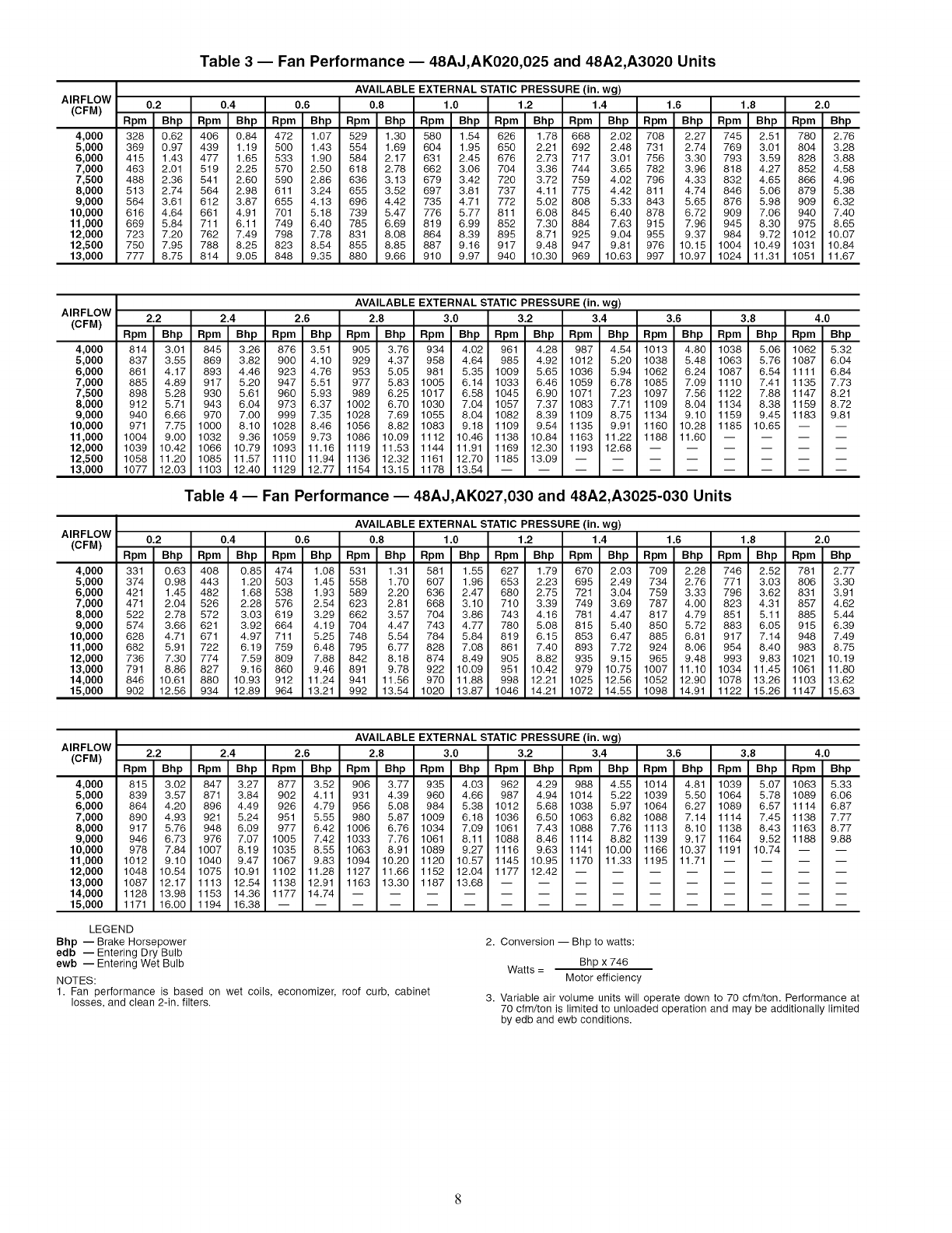
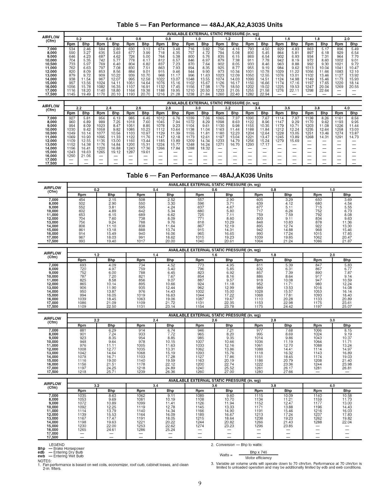
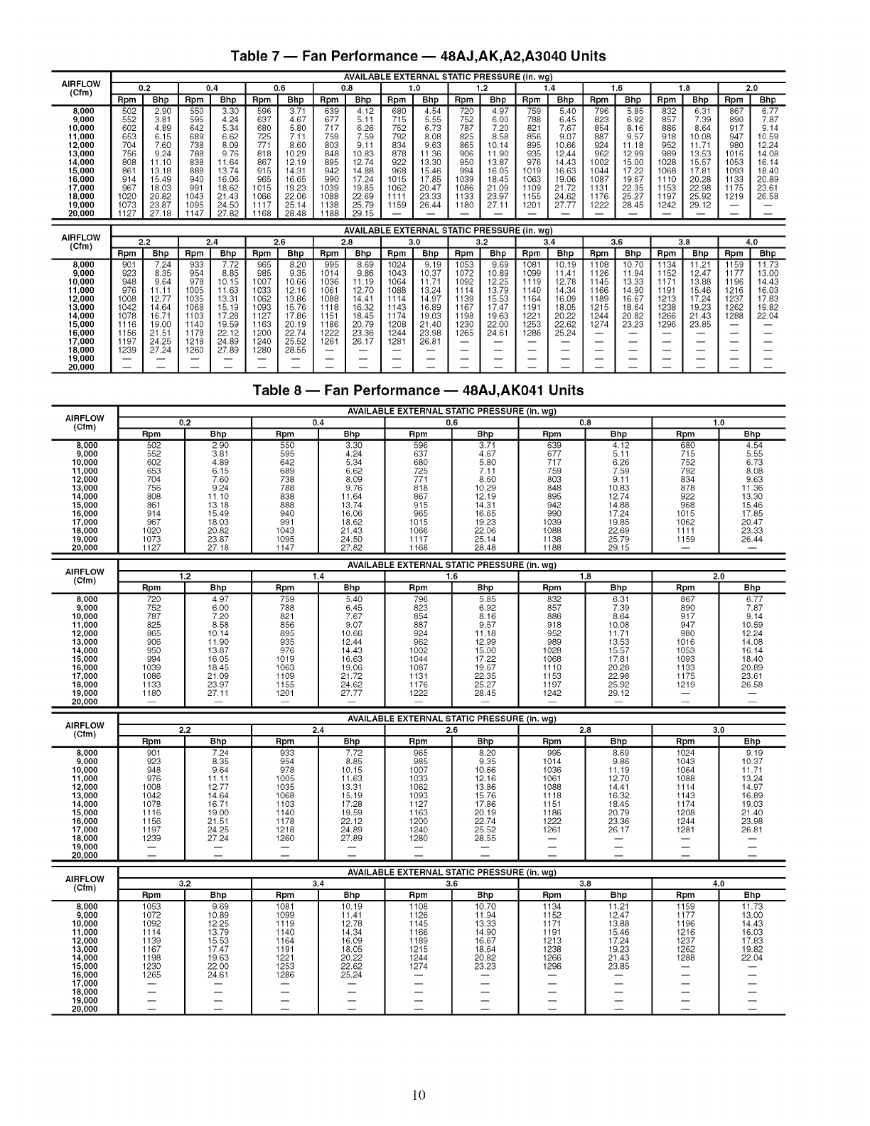
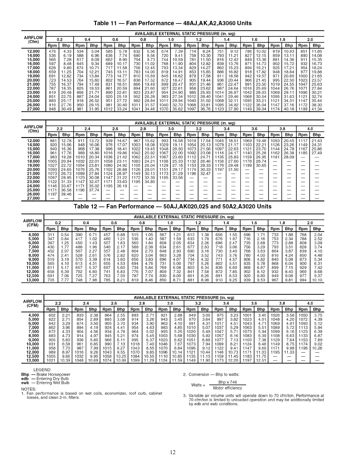
Evaporator Fan -- Fan belt and fixed pulleys are factory-
installed. See Tables 3-38 for fan performance. Remove tape
from fan pulley, and be sure that fans rotate in the proper direc-
tion. See Table 39 for motor limitations. See Tables 40A and
40B for air quantity limits. Static pressure drop for power
exhaust is negligible. To alter fan performance, see Evaporator
Fan Performance Adjustment section on page 130.
Controls EUse the following steps for the controls:
IMPORTANT: The unit is shipped with the unit control ]
disabled. To enable the control, set Local Machine Disable I
(Service Test-gSTOP) to No.
1. Set any control configurations that are required (field-
installed accessories, etc.). The unit is factory configured
for all appropriate factory-installed options.
2. Enter unit set points. The unit is shipped with the set point
default values. If a different set point is required use the
scrolling marquee, Navigatoff M accessory or Service
Tool software to change the configuration valves.
3. If the internal unit schedules are going to be used config-
ure the Occupancy schedule.
4. Verify that the control time periods progralnmed meet
current requirements.
5. Using Service Test mode, verify operation of all major
components.
6. If the unit is a VAV unit make sure to configure the VFD
static pressure set point using the display. To checkout the
VFD use the VFD instructions shipped with the unit.
Gas Heat -- Verifygas pressure before turning on gas heat
as follows:
1. Turn off field-supplied manual gas stop, located external
to the unit.
2. Connect pressure gages to supply gas tap, located at field-
supplied manual shutoffvalves.
3. Connect pressure gages to manifold pressure tap on unit
gas valve.
4. Supply gas pressure must not exceed 13.5 m. wg. Check
pressure at field-supplied shut-offvalve.
5. Turn on manual gas stop and initiate a heating demand.
Jumper R to Wl in the control box to initiate heat.
6. Use the Service Test procedure to verify heat operation.
7. After the unit has mn for several minutes, verify that
incoming pressure is 6.0 m. wg or greater and that the
manifold pressure is 3.5 in wg. If manifold pressure must
be adjusted refer to Gas Valve Adjustment section.
AIRFLOW
(CFM)
4,000
5,000
6,000
7,000
7,500
8,000
9,000
10,000
11,000
12,000
12,500
13,000
Table 3 -- Fan Performance -- 48AJ,AK020,025 and 48A2,A3020 Units
AVAILABLE EXTERNAL STATIC PRESSURE(in. wg)
0.2 0.4 0.6 0.8 1.0 1.2 1.4 1.6 1.8 2.0
Rpm Bhp Rpm Bhp Rpm Bhp Rpm Bhp Rpm Bhp Rpm Bhp Rpm Bhp Rpm Bhp Rpm Bhp Rpm Bhp
328 0.62 406 0.84 472 1.07 529 1.30 580 1.54 626 1.78 668 2.02 708 2.27 745 2.51 780 2.76
369 0.97 439 1.19 500 1.43 554 1.69 604 1.95 650 2.21 692 2.48 731 2.74 769 3.01 804 3.28
415 1.43 477 1.65 533 1.90 584 2.17 631 2.45 676 2.73 717 3.01 756 3.30 793 3.59 828 3.88
463 2.01 519 2.25 570 2.50 618 2.78 662 3.06 704 3.36 744 3.65 782 3.96 818 4.27 852 4.58
488 2.36 541 2.60 590 2.86 636 3.13 679 3.42 720 3.72 759 4.02 796 4.33 832 4.65 866 4.96
513 2.74 564 2.98 611 3.24 655 3.52 697 3.81 737 4.11 775 4.42 811 4.74 846 5.06 879 5.38
564 3.61 612 3.87 655 4.13 696 4.42 735 4.71 772 5.02 808 5.33 843 5.65 876 5.98 909 6.32
616 4.64 661 4.91 701 5.18 739 5.47 776 5.77 811 6.08 845 6.40 878 6.72 909 7.06 940 7.40
669 5.84 711 6.11 749 6.40 785 6.69 819 6.99 852 7.30 884 7.63 915 7.96 945 8.30 975 8.65
723 7.20 762 7.49 798 7.78 831 8.08 864 8.39 895 8.71 925 9.04 955 9.37 984 9.72 1012 10.07
750 7.95 788 8.25 823 8.54 855 8.85 887 9.16 917 9.48 947 9.81 976 10.15 1004 10.49 1031 10.84
777 8.75 814 9.05 848 9.35 880 9.66 910 9.97 940 10.30 969 10.63 997 10.97 1024 11.31 1051 11.67
AIRFLOW
(CFM)
4,000
5,000
6,000
7,000
7,500
8,000
9,000
10,000
11,000
12,000
12,500
13,000
AIRFLOW
(CFM)
4,000
5,000
6,000
7,000
8,000
9,000
10,000
11,000
12,000
13,000
14,000
15,000
AVAILABLE EXTERNAL STATIC PRESSURE (in. wg)
2.2 2.4 2.6 2.8 3.0 3.2 3.4 3.6 3.8 4.0
Rpm Bhp Rpm Bhp Rpm Bhp Rpm Bhp Rpm Bhp Rpm Bhp Rpm Bhp Rpm Bhp Rpm Bhp Rpm Bhp
814 3.01 845 3.26 876 3.51 905 3.76 934 4.02 961 4.28 987 4.54 1013 4.80 1038 5.06 1062 5.32
837 3.55 869 3.82 900 4.10 929 4.37 958 4.64 985 4.92 1012 5.20 1038 5.48 1063 5.76 1087 6.04
861 4.17 893 4.46 923 4.76 953 5.05 981 5.35 1009 5.65 1036 5.94 1062 6.24 1087 6.54 1111 6.84
885 4.89 917 5.20 947 5.51 977 5.83 1005 6.14 1033 6.46 1059 6.78 1085 7.09 1110 7.41 1135 7.73
898 5.28 930 5.61 960 5.93 989 6.25 1017 6.58 1045 6.90 1071 7.23 1097 7.56 1122 7.88 1147 8.21
912 5.71 943 6.04 973 6.37 1002 6.70 1030 7.04 1057 7.37 1083 7.71 1109 8.04 1134 8.38 1159 8.72
940 6.66 970 7.00 999 7.35 1028 7.69 1055 8.04 1082 8.39 1109 8.75 1134 9.10 1159 9.45 1183 9.81
971 7.75 1000 8.10 1028 8.46 1056 8.82 1083 9.18 1109 9.54 1135 9.91 1160 10.28 1185 10.65 -- --
1004 9.00 1032 9.36 1059 9.73 1086 10.09 1112 10.46 1138 10.84 1163 11.22 1188 11.60 ....
1039 10.42 1066 10.79 1093 11.16 1119 11.53 1144 11.91 1169 12.30 1193 12.68 ......
1058 11.20 1085 11.57 1110 11.94 1136 12.32 1161 12.70 1185 13.09 ........
1077 12.03 1103 12.40 1129 12.77 1154 13.15 1178 13.54 ..........
Table 4 -- Fan Performance -- 48AJ,AK027,030 and 48A2,A3025-030 Units
AVAILABLE EXTERNAL STATIC PRESSURE (in. wg)
0.2 0.4 0.6 0.8 1.0 1.2 1.4 1.6 1.8 2.0
Rpm Bhp Rpm Bhp Rpm Bhp Rpm Bhp Rpm Bhp Rpm Bhp Rpm Bhp Rpm Bhp Rpm Bhp Rpm Bhp
331 0.63 408 0.85 474 1.08 531 1.31 581 1.55 627 1.79 670 2.03 709 2.28 746 2.52 781 2.77
374 0.98 443 1.20 503 1.45 558 1.70 607 1.96 653 2.23 695 2.49 734 2.76 771 3.03 806 3.30
421 1.45 482 1.68 538 1.93 589 2.20 636 2.47 680 2.75 721 3.04 759 3.33 796 3.62 831 3.91
471 2.04 526 2.28 576 2.54 623 2.81 668 3.10 710 3.39 749 3.69 787 4.00 823 4.31 857 4.62
522 2.78 572 3.03 619 3.29 662 3.57 704 3.86 743 4.16 781 4.47 817 4.79 851 5.11 885 5.44
574 3.66 621 3.92 664 4.19 704 4.47 743 4.77 780 5.08 815 5.40 850 5.72 883 6.05 915 6.39
628 4.71 671 4.97 711 5.25 748 5.54 784 5.84 819 6.15 853 6.47 885 6.81 917 7.14 948 7.49
682 5.91 722 6.19 759 6.48 795 6.77 828 7.08 861 7.40 893 7.72 924 8.06 954 8.40 983 8.75
736 7.30 774 7.59 809 7.88 842 8.18 874 8.49 905 8.82 935 9.15 965 9.48 993 9.83 1021 10.19
791 8.86 827 9.16 860 9.46 891 9.78 922 10.09 951 10.42 979 10.75 1007 11.10 1034 11.45 1061 11.80
846 10.61 880 10.93 912 11.24 941 11.56 970 11.88 998 12.21 1025 12.56 1052 12.90 1078 13.26 1103 13.62
902 12.56 934 12.89 964 13.21 992 13.54 1020 13.87 1046 14.21 1072 14.55 1098 14.91 1122 15.26 1147 15.63
AIRFLOW
(CFM)
4,000
5,000
6,000
7,000
8,000
9,000
10,000
11,000
12,000
13,000
14,000
15,000
AVAILABLE EXTERNAL STATIC PRESSURE (in. wg)
2.2 2.4 2.6 2.8 3.0 3.2 3.4 3.6 3.8 4.0
Rpm Bhp Rpm Bhp Rpm Bhp Rpm Bhp Rpm Bhp Rpm Bhp Rpm Bhp Rpm Bhp Rpm Bhp Rpm Bhp
815 3.02 847 3.27 877 3.52 906 3.77 935 4.03 962 4.29 988 4.55 1014 4.81 1039 5.07 1063 5.33
839 3.57 871 3.84 902 4.11 931 4.39 960 4.66 987 4.94 1014 5.22 1039 5.50 1064 5.78 1089 6.06
864 4.20 896 4.49 926 4.79 956 5.08 984 5.38 1012 5.68 1038 5.97 1064 6.27 1089 6.57 1114 6.87
890 4.93 921 5.24 951 5.55 980 5.87 1009 6.18 1036 6.50 1063 6.82 1088 7.14 1114 7.45 1138 7.77
917 5.76 948 6.09 977 6.42 1006 6.76 1034 7.09 1061 7.43 1088 7.76 1113 8.10 1138 8.43 1163 8.77
946 6.73 976 7.07 1005 7.42 1033 7.76 1061 8.11 1088 8.46 1114 8.82 1139 9.17 1164 9.52 1188 9.88
978 7.84 1007 8.19 1035 8.55 1063 8.91 1089 9.27 1116 9.63 1141 10.00 1166 10.37 1191 10.74 -- --
1012 9.10 1040 9.47 1067 9.83 1094 10.20 1120 10.57 1145 10.95 1170 11.33 1195 11.71 ....
1048 10.54 1075 10.91 1102 11.28 1127 11.66 1152 12.04 1177 12.42 ........
1087 12.17 1113 12.54 1138 12.91 1163 13.30 1187 13.68 ..........
1128 13.98 1153 14.36 1177 14.74 ..............
1171 16.00 1194 16.38 ................
LEGEND
Bhp -- Brake Horsepower
edb -- Entering Dry Bulb
ewb -- Entering Wet Bulb
NOTES:
1. Fan performance is based on wet coils, economizer, roof curb, cabinet
losses, and clean 2-in. filters.
2. Conversion -- Bhp to watts:
Bhp x 746
Watts = Motor efficiency
3. Variable air volume units will operate down to 70 cfm/ton. Performance at
70 cfm/ton is limited to unloaded operation and may be additionally limited
by edb and ewb conditions.
AIRFLOW
(Cfm)
7,000
8,000
9,000
10,000
10,500
11,000
12,000
13,000
14,000
15,000
16,000
17,000
17,500
AIRFLOW
(Of m)
7,000
8,000
9,000
10,000
10,500
11,000
12,000
13,000
14,000
15,000
16,000
17,000
17,500
Table 5 -- Fan Performance -- 48AJ,AK,A2,A3035 Units
AVAILABLE EXTERNAL STATIC PRESSURE (in. wg)
0.2 0.4 0.6 0.8 1.0 1.2 1.4 1.6 1.8 2.0
Rpm Bhp Rpm Bhp Rpm Bhp Rpm Bhp Rpm Bhp Rpm Bhp Rpm Bhp Rpm Bhp Rpm Bhp Rpm Bhp
534 2.46 584 2.80 630 3.13 674 348 716 3.82 756 4.16 793 450 829 4.83 863 517 896 5.49
590 3.27 635 3.63 677 3.99 718 4.35 757 4.72 794 5.08 830 5.45 864 5.81 897 6.18 929 6.54
646 4.23 687 4.62 726 5.00 764 5.38 800 5.76 835 6.18 869 6.54 902 6.93 934 7.31 964 7.70
704 5.35 742 5.77 778 6.17 812 6.57 846 6.97 879 7.38 911 7.78 942 8.19 972 8.60 1002 9.01
733 5.97 769 6.40 804 6.82 837 7.23 870 7.64 902 8.05 933 8.46 963 8.88 992 9.30 1021 9.72
762 6.63 797 7.08 830 7.81 863 7.93 894 8.38 925 8.77 955 9.19 984 9.62 1013 10.04 1041 10.47
820 8.09 853 8.56 884 9.01 915 9.46 944 9.90 973 10.34 1001 10.78 1029 11.22 1056 11.66 1083 12.10
879 9.72 909 10.22 939 1O.70 968 11.17 996 11.63 1023 12.09 1050 12.55 1076 13.01 1102 13.46 1127 13.92
938 11.54 967 12.07 995 12.58 1022 13.07 1048 13.55 1074 14.03 1099 14.51 1124 14.98 1149 15.46 1173 15.93
997 13.86 1024 14.11 1051 14.64 1076 18.16 1102 15.67 1126 16.17 1150 16.66 1174 17.16 1197 17.65 1220 18.14
1056 18.78 1082 16.35 1107 16.91 1132 17.45 1186 17.98 1179 18.50 1202 19.02 1225 19.53 1247 20.04 1269 20.55
1116 18.20 1140 18.80 1164 19.38 1188 19.95 1210 20.50 1233 21.05 1255 21.58 1276 22.11 1298 22.64 -- --
1145 19.49 1170 20.10 1193 20.70 1216 21.28 1238 21.84 1260 22.40 1282 22.94 ......
AVAILABLE EXTERNAL STATIC PRESSURE(in. wg)
2.2 2.4 2,6 2.8 3.0 3.2 3.4 3.6 3.8 4.0
Rpm Bhp Rpm Bhp Rpm Bhp Rpm Bhp Rpm Bhp Rpm Bhp Rpm Bhp Rpm Bhp Rpm Bhp Rpm Bhp
927 5.81 956 6.13 985 6.45 1012 6.76 1039 7.06 1065 7.37 1090 7.67 1114 7.97 1138 8.26 1161 8.56
960 6.69 989 7.25 1018 7.60 1045 7.94 1072 8.29 1098 8.63 1122 8.96 1147 9.29 1170 9.62 1193 9.95
994 8.09 1023 8.47 1051 8.85 1078 9.23 1104 9.61 1130 9.98 1155 10.35 1179 10.71 1203 11.08 1226 11.44
1030 9.42 1058 9.82 1085 10.23 1112 10.64 1138 11.04 1163 11.44 1188 11.84 1212 12.24 1235 12.64 1258 13.03
1049 10.14 1077 10.66 1103 10.97 1129 11.39 1155 11.81 1180 12.23 1204 12.64 1228 13.05 1251 13.46 1274 13.87
1069 10.90 1095 11.33 1122 11.76 1147 12,18 1173 12.61 1197 13.04 1221 13.47 1245 13.89 1268 14.31 1291 14.73
1109 12.55 1135 13.00 1160 13.44 1185 13.89 1209 14.34 1233 14.79 1256 15.24 1279 15.69 ....
1152 14.38 1176 14.84 1200 16.31 1224 15.77 1248 16.24 1271 16.70 1293 17.17 ......
1196 16.41 1220 16.88 1243 17.36 1266 17.84 1288 18.32 ..........
1243 18.63 1265 19.12 1287 19.61 ..............
1290 21.06 ..................
Table 6-- Fan Performance -- 48AJ,AK036 Units
AVAILABLE EXTERNAL STATIC PRESSURE (in. wg)
AIRFLOW
(Cfm) 0.2 0.4 0.6 0.8
Rpm
454
5O2
552
6O2
653
7O4
756
8O8
861
914
967
993
Bhp
2.15
2.90
3.81
4.89
6.15
7.60
9.24
11.10
13.18
16.49
18.03
19.40
7,000
8,000
9,000
10,000
11,000
12,000
13,000
14,000
15,000
16,000
17,000
17,500
Rpm
5O8
55O
595
642
689
738
788
838
888
94O
991
1017
Bhp
2.52
3.30
4.24
5.34
6.62
8.09
9.76
11.64
13.74
16.06
18.62
20.00
Rpm
557
596
637
68O
725
771
818
867
915
965
1015
1040
Bhp
2.90
3.71
4.67
5.80
7.11
8.60
10.29
12.19
14.31
16.66
19.23
20.61
Rpm
6O5
639
677
717
759
8O3
848
895
942
99O
1039
1064
Bhp
3.29
4.12
5.11
6.26
7.59
9.11
10.83
12.74
14.88
17.24
19.86
21.24
1.0
Rpm
650
680
715
752
792
834
878
922
968
1015
1062
1086
Bhp
3.69
4.54
5.55
6.73
8.08
9.63
11.36
13.30
15.46
17.86
20.47
21.87
AVAILABLE EXTERNAL STATIC PRESSURE (in. wg)
AIRFLOW 1.2 1.4 1.6
(cfm)
7,000
8,000
9,000
10,000
11,000
12,000
13,000
14,000
15,000
16,000
17,000
17,500
Rpm
693
72O
752
787
825
865
9O6
95O
994
1039
1086
1109
Bhp
4.09
4.97
6.00
7.20
8.58
10.14
11.90
13.87
16.05
18.46
21.09
22.60
Rpm
734
759
788
821
856
895
935
976
1019
1063
1109
1131
Bhp
4.52
5.40
6.45
7.67
9.07
10.66
12.44
14.43
16.63
19.06
21.72
23.14
Rpm
773
796
823
854
887
924
962
1002
1044
1087
1131
1154
Bhp
4.95
5.85
6.92
8.16
9.57
11.18
12.99
15.00
17.22
19.67
22.36
23.78
Rpm
811
832
857
886
918
952
989
1028
1068
1110
1153
1175
1.8
Bhp
5.39
6.31
7.39
6.64
10.06
11.71
13.53
15.57
17.61
20.26
22.96
24.42
2.0
Rpm
847
867
890
917
947
98O
1018
1053
1093
1133
1175
1197
Bhp
5.83
6.77
7.87
9.14
10.59
12.24
14.08
16.14
18.40
20.89
23.61
26.07
AVAILABLE EXTERNAL STATIC PRESSURE (in. wg)
AIRFLOW 2.2 2,4 2,6
(cfm)
7,000
8,000
9,000
10,000
11,000
12,000
13,000
14,000
15,000
16,000
17,000
17,500
Rpm
881
901
923
948
976
1008
1042
1078
1116
1156
1197
1218
Bhp
6.29
7.24
8.35
9.64
11.11
12.77
14.64
16.71
19.00
21.61
24.26
26.71
Rpm
914
933
954
978
1005
1035
1068
1103
1140
1178
1218
1239
Bhp
6.74
7.72
8.85
10.15
11.63
13.31
15.19
17.28
19.69
22.12
24.89
26.36
Rpm
946
965
985
1007
1033
1062
1093
1127
1163
1200
1240
1260
Bhp
7.21
8.20
9.35
10.66
12.16
13.86
15.76
17.86
20.19
22.74
26.62
27.00
Rpm
977
995
1014
1036
1061
1088
1118
1151
1186
1222
1261
1280
2.8
Bhp
7.68
8.69
9.86
11.19
12.70
14.41
16.32
18.45
20.79
23.36
26.17
27.66
3.0
Rpm
1006
1024
1043
1064
1088
1114
1143
1174
1208
1244
1281
Bhp
8,15
9.19
10.37
11.71
13.24
14.97
16.89
19.03
21.40
23.98
26.81
AVAILABLE EXTERNAL STATIC PRESSURE (in. wg)
AIRFLOW
(Cfm) 3.2 3.4 3.6
7,000
8,000
9,000
10,000
11,000
12,000
13,000
14,000
15,000
16,000
17,000
17,500
Rpm
1035
1053
1072
1092
1114
1139
1167
1198
1230
1265
Bhp
8.63
9.69
10.89
12.25
13.79
15.53
17.47
19.63
22.00
24.61
Bhp
9.60
10.70
11.94
13.33
14.90
16.67
18.64
20.82
23.23
Rpm
1062
1081
1099
1119
1140
1164
1191
1221
1253
1286
Bhp
9.11
10.19
11.41
12.78
14.34
16.09
18.05
20.22
22.62
25.24
LEGEND
Bhp -- Brake Horsepower
edb -- Entering Dry Bulb
ewb -- Entering Wet Bulb
NOTES:
1. Fan performance is based on wet coils economizer roof curb, cabinet losses and clean
2-in. filters.
Rpm
1089
1108
1126
1145
1166
1189
1215
1244
1274
Rpm
1115
1134
1152
1171
1191
1213
1238
1266
1296
3.8
Bhp
10.09
11.21
12,47
13.88
18.46
17.24
19.23
21.43
23.86
2. Conversion -- Bhp to watts:
Bhp x 746
Watts = Motor efficiency
4.0
Rpm
1140
1159
1177
1196
1216
1237
1262
1288
Bhp
10.58
11.73
13.00
14.43
16.03
17.83
19.82
22.04
3. Variable air volume units will operate down to 70 cfm/ton. Performance at 70 cfm/ton is
limited to unloaded operation and may be additionally limited by edb and ewb conditions.
AIRFLOW
(Cfm)
8,000
9,000
10,000
11,000
12,000
13,000
14,000
15,000
16,000
17,000
18,000
19,000
20,000
AIRFLOW
(Of m)
8,000
9,000
10,000
11,000
12,000
13,000
14,000
15,000
16,000
17,000
18,000
19,000
20,000
Table 7- Fan Performance- 48AJ,AK,A2,A3040 Units
AVAILABLE EXTERNAL STATIC PRESSURE (in. wg)
0.2 0.4 0.6 0.8 1.0 1.2 1.4 1.6 1.8 2.0
Rpm Bhp Rpm Bhp Rpm Bhp Rpm Bhp Rpm Bhp Rpm Bhp Rpm Bhp Rpm Bhp Rpm Bhp Rpm Bhp
502 2,90 550 330 596 3.71 639 4.12 680 454 720 4.97 759 540 796 5.85 832 6.31 867 677
552 3.81 595 4.24 637 4.67 677 5.11 715 5.55 752 6.00 788 6.45 823 6.92 857 7.39 890 7.87
602 4.89 642 5.34 680 5.80 717 6.26 752 6.73 787 7.20 821 7.67 854 8,16 886 8.64 917 9.14
653 6.15 689 6.62 725 7.11 759 7.59 792 8,08 825 8.58 856 9.07 887 9.57 918 10.08 947 10.59
704 7.60 738 8.09 771 8.60 803 9.11 834 9.63 865 10.14 895 10.66 924 11.18 952 11.71 980 12.24
756 9.24 788 9.76 818 10.29 848 10.83 878 11.36 906 11.90 935 12.44 962 12.99 989 13.53 1016 14.08
808 11.10 838 11.64 867 12.19 895 12.74 922 13.30 950 13.87 976 14.43 1002 15.00 1028 15.57 1053 16.14
861 13.18 888 13.74 915 14.31 942 14.88 968 15.46 994 16.05 1019 16.63 1044 17.22 1068 17.81 1093 18.40
914 15.49 940 16.06 965 16.65 990 17.24 1015 17.85 1039 18,45 1063 19.06 1087 19.67 1110 20.28 1133 20.89
967 18.03 991 18.62 1015 19.23 1039 19.85 1062 20.47 1086 21.09 1109 21.72 1131 22.35 1153 22.98 1175 23.61
1020 20.82 1043 21.43 1066 22.06 1088 22.69 1111 23.33 1133 23.97 1155 24.62 1176 25.27 1197 25.92 1219 26.58
1073 23.87 1095 24.50 1117 25.14 1138 25.79 1159 26.44 1180 27.11 1201 27.77 1222 28.45 1242 29.12 -- --
1127 27.18 1147 27.82 1168 28.48 1188 29.15 ............
AVAILABLE EXTERNAL STATIC PRESSURE (in. wg)
2.2 2.4 2,6 2.8 3.0 3.2 3.4 3.6 3.8 4.0
Rpm Bhp Rpm Bhp Rpm Bhp Rpm Bhp Rpm Bhp Rpm Bhp Rpm Bhp Rpm Bhp Rpm Bhp Rpm Bhp
901 7.24 933 772 965 8,20 995 8.69 1024 919 1053 9.69 1081 10.19 1108 10.70 1134 11.21 1159 11.73
923 8.35 954 8.85 985 9.35 1014 9.86 1043 10.37 1072 10.89 1099 11.41 1126 11.94 1152 12,47 1177 13.00
948 9.64 978 10.15 1007 10.66 1036 11.19 1064 11.71 1092 12,25 1119 12.78 1145 13.33 1171 13.88 1196 14.43
976 11.11 1005 11.63 1033 12,16 1061 12.70 1088 13.24 1114 13.79 1140 14.34 1166 14.90 1191 15.46 1216 16.03
1008 12.77 1035 13.31 1062 13.86 1088 14.41 1114 14.97 1139 15.53 1164 16.09 1189 16.67 1213 17.24 1237 17.83
1042 14.64 1068 15.19 1093 15.76 1118 16.32 1143 16.89 1167 17.47 1191 18.05 1215 18.64 1238 19.23 1262 19.82
1078 16.71 1103 17.28 1127 17.86 1151 18.45 1174 19.03 1198 19.63 1221 20.22 1244 20.82 1266 21.43 1288 22.04
1116 19.00 1140 19.59 1163 20.19 1186 20.79 1208 21.40 1230 22.00 1253 22.62 1274 23.23 1296 23.85 -- --
1156 21.51 1178 22.12 1200 22.74 1222 23.36 1244 23.98 1265 24.61 1286 25.24 ......
1197 24.25 1218 24.89 1240 25.52 1261 26.17 1281 26.81 ..........
1239 27.24 1260 27.89 1280 28.55 ..............
Table 8-- Fan Performance -- 48AJ,AK041 Units
AIRFLOW AVAILABLE EXTERNAL STATIC PRESSURE (in. wg)
(Cfm) 0.2 0.4 0.6 0.8
Rpm
5O2
552
6O2
653
7O4
756
808
861
914
967
1020
1073
1127
Bhp
2.90
3.81
4.89
6.15
7.60
9.24
11.10
13.18
15.49
18.03
20.82
23.87
27.18
8,000
9,000
10,000
11,000
12,000
13,000
14,000
15,000
16,000
17,000
18,000
19,000
20,000
Rpm
55O
595
642
689
738
788
838
888
94O
991
1043
1095
1147
Bhp
3.30
4.24
5.34
6.62
8.09
9.76
11.64
13.74
16.06
18.62
21.43
24.80
27.82
Rpm
596
637
68O
725
771
818
867
915
965
1015
1066
1117
1168
Bhp
3.71
4.67
5.80
7.11
8.60
10.29
12.19
14.31
16.65
19.23
22.06
28.14
28.48
Rpm
639
677
717
759
8O3
848
895
942
99O
1039
1088
1138
1188
AIRFLOW AVAILABLE EXTERNAL STATIC PRESSURE (in. wg)
(Cfm) 1.2 1.4 1.6
Rpm
720
752
787
825
865
906
950
994
1039
1086
1133
1180
8,000
9,000
10,000
11,000
12,000
13,000
14,000
15,000
16,000
17,000
18,000
19,000
20,000
Bhp
4.97
6.00
7.20
8.58
10.14
11.90
13.87
16.05
18.45
21.09
23.97
27.11
Rpm
759
788
821
856
895
935
976
1019
1063
1109
1155
1201
Bhp
5.40
6.45
7.67
9.07
10.66
12.44
14.43
16.63
19.06
21.72
24.62
27.77
Rpm
796
823
854
887
924
962
1002
1044
1087
1131
1176
1222
Bhp
5.85
6.92
8.16
9.57
11.18
12.99
15.00
17.22
19.67
22.38
28.27
28.48
Rpm
832
857
886
918
952
989
1028
1068
1110
1153
1197
1242
Bhp
4.12
5.11
6.26
7.59
9.11
10.83
12.74
14.88
17.24
19.88
22.69
25.79
29.18
Rpm
68O
715
752
792
834
878
922
968
1015
1062
1111
1159
AIRFLOW AVAILABLE EXTERNAL STATIC PRESSURE (in. wg)
(Cfm) 2.2 2,4 2,6
Rpm
901
923
948
976
1008
1042
1078
1116
1156
1197
1239
8,000
9,000
10,000
11,000
12,000
13,000
14,000
15,000
16,000
17,000
18,000
19,000
20,000
Bhp
7.24
8.35
9.64
11.11
12.77
14.64
16.71
19.00
21.81
24.28
27.24
Rpm
933
954
978
1005
1035
1068
1103
1140
1178
1218
1260
Bhp
7.72
8.85
10.15
11.63
13.31
15.19
17.28
19.59
22.12
24.89
27.89
1.8
Bhp
631
739
864
10.08
11.71
13.83
15.87
17.81
20.28
22.98
25.92
29.12
Rpm
867
89O
917
947
98O
1016
1053
1093
1133
1175
1219
Rpm
965
985
1007
1033
1062
1093
1127
1163
1200
1240
1280
Bhp
8.20
9.35
10.66
12.16
13.86
15.76
17.86
20.19
22.74
28.82
28.55
Rpm
995
1014
1036
1061
1088
1118
1151
1186
1222
1261
AIRFLOW AVAILABLE EXTERNAL STATIC PRESSURE (in. wg)
(Cfm) 3.2 3.4 3.6
Rpm
1053
1072
1092
1114
1139
1167
1198
1230
1265
8,000
9,000
10,000
11,000
12,000
13,000
14,000
15,000
16,000
17,000
18,000
19,000
20,000
2.8
Bhp
869
9.86
11.19
12.70
14.41
16.32
18.48
20.79
23.36
26.17
Rpm
1024
1043
1064
1088
1114
1143
1174
1208
1244
1281
Bhp
9.69
10.89
12.25
13.79
15.53
17.47
19.63
22.00
24.61
Rpm
1081
1099
1119
1140
1164
1191
1221
1253
1286
Bhp
10.19
11.41
12.78
14.34
16.09
18.05
20.22
22.62
25.24
Rpm
1108
1126
1145
1166
1189
1215
1244
1274
Bhp
10.70
11.94
13.33
14.90
16.67
18.64
20.82
23.23
Rpm
1134
1152
1171
1191
1213
1238
1266
1296
3.8
Bhp
11.21
12,47
13.88
15.46
17.24
19.23
21.43
23.85
Rpm
1159
1177
1196
1216
1237
1262
1288
1.0
Bhp
454
555
673
808
963
11.36
13.30
15.46
17.85
20.47
23.33
26.44
2,0
Bhp
677
787
914
1059
12.24
14.08
16.14
18.40
20.89
23.61
26.58
3.0
Bhp
9.19
10.37
11.71
13.24
14.97
16.89
19.03
21.40
23.98
26.81
4,0
Bhp
11.73
1300
1443
1603
1783
1982
22.04
[0
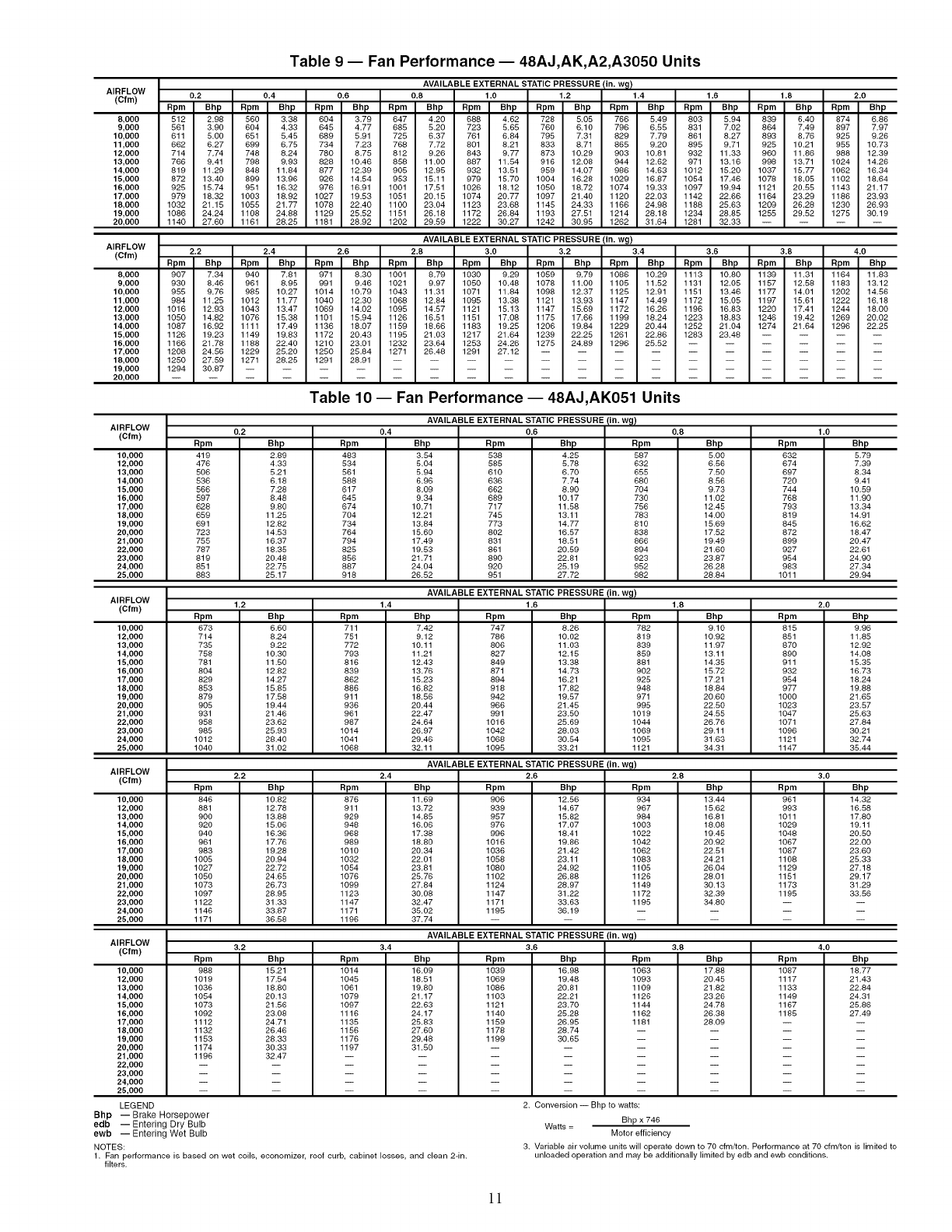
Table 9 -- Fan Performance -- 48AJ,AK,A2,A3050 Units
AIRFLOW
(Cfm)
8,000
9,000
10,000
11,000
12,000
13,000
14,000
15,000
16,000
17,000
18,000
19,000
20,000
AVAILABLE EXTERNAL STATIC PRESSURE fin. w_!
0.2 0.4 0.6 0.8 1.0 1.2 1.4 1.6 1.8 2.0
Bpm Bhp Bpm Bbp Bpm Bhp Bpm Bhp Bpm Bhp Bpm Bhp Bpm Bbp Bprn Bhp Bprn Bhp Bpm Bhp
512 2.98 560 3.38 604 3.79 647 4.20 688 4.62 728 5.05 766 5.49 803 5.94 839 6.40 874 6.86
561 3.90 604 4.33 645 4.77 685 5.20 723 5.65 760 6.10 796 6.55 831 7.02 864 7.49 897 7.97
611 5.00 651 5.45 689 5.91 725 6.37 761 6.84 795 7.31 829 7.79 861 8.27 893 8,76 925 9.26
662 6.27 699 6.75 734 7.23 768 7,72 801 8.21 833 8.71 865 9.20 895 9,71 925 10.21 955 10.73
714 7,74 748 8.24 780 8.75 812 9.26 843 9,77 873 10.29 903 10.81 932 11.33 960 11.86 988 12.39
766 9.41 798 9.93 828 10.46 858 11.00 887 11.54 916 12.08 944 12.62 971 13.16 998 13.71 1024 14.26
819 11.29 848 11.84 877 12.39 905 12.95 932 13.51 959 14,07 986 14.63 1012 15.20 1037 15.77 1062 16.34
872 13.40 899 13.96 926 14.54 953 15.11 979 15.70 1004 16.28 1029 16.87 1054 17.46 1078 18,05 1102 18.64
925 15.74 951 16.32 976 16.91 1001 17,51 1026 18.12 1050 18.72 1074 19.33 1097 19.94 1121 20.55 1143 21.17
979 18.32 1003 18.92 1027 19.53 1051 20.15 1074 20.77 1097 21.40 1120 22.03 1142 22.66 1164 23.29 1186 23.93
1032 21.15 1055 21.77 1078 22.40 1100 23.04 1123 23.68 1145 24.33 1166 24.98 1188 25.63 1209 26,28 1230 26.93
1086 24.24 1108 24.88 1129 25.52 1151 26,18 1172 26.84 1193 27.51 1214 28.18 1234 28.85 1255 29.52 1275 30.19
1140 27.60 1161 28.25 1181 28.92 1202 29.59 1222 30.27 1242 30.95 1262 31.64 1281 32.33 ....
AIRFLOW
(Cfm)
8,000
9,000
10,000
11,000
12,000
13,000
14,000
15,000
16,000
17,000
18,000
19,000
20,000
AVAILABLE EXTERNAL STATIC PRESSURE (in. wg)
2.2 2.4 2.6 2.8 3.0 3.2 3.4 3.6 3.8 4.0
Bpm Bhp Bpm Bbp Bpm Bhp Bpm Bbp Bpm Bhp Bpm Bhp Bpm Bbp Bpm Bhp Bpm Bbp Bpm Bhp
907 7.34 940 7.81 971 8.30 1001 8,79 1030 9.29 1059 9.79 1086 10.29 1113 10.80 1139 11.31 1164 11.83
930 8,46 961 8.95 991 9.46 1021 9.97 1050 10.48 1078 11.00 1105 11.52 1131 12.05 1157 12.58 1183 13.12
955 9.76 986 10.27 1014 10.79 1043 11.31 1071 11.84 1098 12.37 1125 12.91 1151 13.46 1177 14.01 1202 14.56
984 11.25 1012 11.77 1040 12.30 1068 12.84 1096 13.38 1121 13.93 1147 14.49 1172 15.05 1197 15.61 1222 16.18
1016 12.93 1043 13.47 1069 14.02 1095 14.57 1121 15.13 1147 15.69 1172 16.26 1196 16.83 1220 17,41 1244 18.00
1050 14,82 1076 15.38 1101 15.94 1126 16.51 1151 17.08 1175 17,66 1199 18.24 1223 18,83 1246 19.42 1269 20.02
1087 16.92 1111 17.49 1136 18.07 1159 18.66 1183 19.25 1206 19.84 1229 20.44 1252 21.04 1274 21.64 1296 22.25
1126 19.23 1149 19.83 1172 20.43 1195 21.03 1217 21.64 1239 22.25 1261 22.86 1283 23.48 ....
1166 21.78 1188 22.40 1210 23.01 1232 23.64 1253 24.26 1275 24.89 1296 25.52 ......
1208 24.56 1229 25.20 1250 25.84 1271 26.48 1291 27.12 ..........
1250 27.59 1271 28.25 1291 28.91 ..............
1294 30.87 ..................
Table 10 -- Fan Performance -- 48AJ,AK051 Units
AIRFLOW
(Cfm)
10,000
12,000
13,000
14,000
15,000
16,000
17,000
18,000
19,000
20,000
21,000
22,000
23,000
24,000
25,000
Bpm
419
476
506
536
566
597
626
659
691
723
755
787
819
851
883
0.2
Bhp
2.89
4.33
5.21
6.18
7.28
8,48
9.80
11.25
12.82
14.53
16.37
18,35
20.48
22.75
25.17
Bpm
483
534
561
586
617
645
674
7O4
734
764
794
825
856
887
918
0.4
AVAILABLE EXTERNAL STATIC PRESSURE (in. w_)
0.6
Bhp Bpm Bhp Bpm
3.54
5.04
5.94
6.96
8,09
9.34
10.71
12.21
13.84
15.60
17.49
19.53
21.71
24.04
26.62
538 4.25
585 5.78
610 6.70
636 7.74
662 8.90
689 10.17
717 11.68
745 13.11
773 14.77
802 16.57
831 18.51
861 20.59
890 22.81
920 25.19
951 27.72
587
632
655
680
704
730
756
783
810
838
866
894
923
952
982
0.8
Bhp
5.00
6.56
7.50
8.56
9.73
11.02
12.45
14.00
15.69
17.52
19.49
21.60
23.87
26.28
28.84
1.0
Bpm
632
674
697
72o
744
766
793
819
845
872
899
927
954
983
lOll
Bhp
5.79
7.39
8.34
9.41
10.69
11.90
13.34
14.91
16.62
18.47
20.47
22.61
24.90
27.34
29.94
AVAILABLE EXTERNAL STATIC PRESSURE (in. wg)
AIHI=LUW
_,..4)'^'m" 1.2 1.4 1.6
10,000
12,000
13,000
14,000
15,000
16,000
17,000
18,000
19,000
20,000
21,000
22,000
23,000
24,000
25,000
gpm
673
714
735
758
781
804
829
853
879
905
931
956
985
1012
1040
Bhp
6.60
8,24
9.22
10.30
11.50
12.82
14.27
15.85
17.58
19.44
21.46
23.62
25.93
28.40
31.02
gpm
711
751
772
793
816
839
862
886
911
936
961
987
1014
1041
1068
Bhp
7,42
9.12
10.11
11.21
12.43
13.76
15.23
16.82
18.56
20.44
22.47
24.64
26.97
29.46
32.11
Bprn
747
786
806
827
849
871
894
918
942
966
991
1016
1042
1068
1095
Bhp Bpm
8.26 782
10.02 819
11.03 839
12.15 859
13.38 881
14.73 902
16.21 925
17.82 948
19.67 971
21.45 995
23.50 1019
25.69 1044
28.03 1069
30.64 1095
33.21 1121
AVAILABLE EXTERNAL STATIC PRESSURE (in. wg)
AIRFLOW 2.2 2.4 2.6
(Cfm) Bpm
876
911
929
948
968
989
1010
1032
1054
1076
1099
1123
1147
1171
1196
10,000
12,000
13,000
14,000
15,000
16,000
17,000
18,000
19,000
20,000
21,000
22,000
23,000
24,000
25,000
Bhp
10.82
12.78
13.88
15.06
16.36
17.76
19,28
20.94
22.72
24.65
26.73
28.95
31.33
33.87
36.58
Bpm
846
881
900
920
940
961
983
1005
1027
1050
1073
1097
1122
1146
1171
Bhp
11.69
13.72
14.85
16.06
17.38
16.80
20.34
22.01
23.81
25.76
27.84
30.06
32.47
35.02
37.74
Rpm
906
939
957
976
996
1016
1036
1058
1060
1102
1124
1147
1171
1195
Bhp Rpm
12.56 934
14.67 967
15.82 984
17.07 1003
18.41 1022
19.86 1042
21.42 1062
23.11 1083
24.92 1105
26.88 1126
28.97 1149
31.22 1172
33.63 1195
36.19
1.8
Bhp
9.10
10.92
11.97
13.11
14.35
15.72
17.21
18.84
20.60
22.50
24.55
26.76
29.11
31.63
34.31
2.8
Bhp
13.44
15.62
16.81
16.08
19.45
20.92
22.51
24.21
26.04
26.01
30.13
32.39
34.60
AVAILABLE EXTERNAL STATIC PRESSURE (in. wg)
AIRFLOW
(Cfm) 3.2 3.4 3.6 3.8
Bhp
15.21
17.54
18,80
20.13
21.56
23.06
24.71
26.46
28.33
30.33
32.47
10,000
12,000
13,000
14,000
15,000
16,000
17,000
18,000
19,000
20,000
21,000
22,000
23,000
24,000
25,000
LEGEND
Bhp
16.09
18.51
19.80
21.17
22.63
24.17
25.83
27.60
29.48
31.60
Bpm
lO14
1045
1061
1079
1097
1116
1135
1156
1176
1197
Bpm
1039
1069
1086
1103
1121
1140
1159
1178
1199
Bhp
16.98
19.48
20.81
22.21
23.70
25.28
26.95
28.74
30.65
Bpm
1063
1093
1109
1126
1144
1162
1181
2. Conversion -- Bhp to watts:
Bhp x 746
Watts =
Motor efficiency
Bpm
988
lO19
lO36
lO54
lO73
1092
1112
1132
1153
1174
1196
Bhp -- Brake Horsepower
edb -- Entering Dry Bulb
ewb -- Entering Wet Bulb
NOTES:
1. Fan performance is based on wet coils, economizer, roof curb, cabinet losses, and clean 2-in.
filters.
Bhp
17.68
20.45
21.82
23.26
24.78
26.38
28.09
2.0
Bprn Bhp
815 9.96
851 11.85
870 12.92
890 14.08
911 15.35
932 16.73
964 18.24
977 19.88
1000 21.65
1023 23.57
1047 25.63
1071 27.84
1096 30.21
1121 32.74
1147 35.44
3.0
Rpm Bhp
961 14.32
993 16.58
1011 17.80
1029 19.11
1046 20.50
1067 22.00
1087 23.60
1106 25.33
1129 27.18
1151 29.17
1173 31.29
1195 33.56
4.0
Bpm Bhp
1087 18.77
1117 21.43
1133 22.84
1149 24.31
1167 25.86
1185 27.49
3. Variable air volume units will operate down to 70 cfm/ton. Performance at 70 cfm/ton is limited to
unloaded operation and may be additionally limited by edb and ewb conditions.
1!
AIRFLOW
(Cfm)
12,000
14,000
15,000
16,000
17,000
18,000
19,000
20,000
21,000
22,000
23,000
24,000
25,000
26,000
27,000
Table 11 -- Fan Performance -- 48AJ,AK,A2,A3060 Units
AVAILABLE EXTERNAL STATIC PRESSURE (in. wg)
0.2 0.4 0.6 0.8 1.0 1.2 1.4 1.6 1.8 2.0
Rpm Bhp Rpm Bhp Rpm Bhp Rpm Bhp Rpm Bhp Rpm Bhp Rpm Bhp Rpm Bhp Rpm Bhp Rpm Bhp
476 4.33 534 5.04 585 5.78 632 6.56 674 7.39 714 8.24 751 9.12 786 10.02 819 10.93 851 11.85
536 6.19 588 6.96 636 7.74 680 8.56 720 9.41 758 10.30 793 11.21 827 12.15 859 13.11 890 14.08
566 7.28 617 8.09 662 8.90 704 9.73 744 10.59 781 11.50 816 12.42 849 13.38 881 14.36 911 15.35
597 8.48 645 9.34 689 10.17 730 11.02 768 11.90 804 12.82 839 13.76 871 14.73 902 15.72 932 16.73
628 9.80 674 10.71 717 11.58 756 12.45 793 13.34 829 14.27 862 15.23 894 16.21 925 17.21 954 18.24
659 11.25 704 12.21 745 13.11 783 14.00 819 14.91 853 15.85 886 16.82 918 17.82 948 18.84 977 19.88
691 12.82 734 13.84 773 14.77 810 15.69 845 16.62 879 17.58 911 18.56 942 19.57 971 20.60 1000 21.65
723 14.53 764 15.60 802 16.57 838 17.52 872 18.47 905 19.44 936 20.44 966 21.45 995 22.50 1023 23.57
755 16.37 794 17.49 831 18.51 866 19.49 899 20.47 931 21.46 961 22.47 991 23.50 1019 24.55 1047 25.63
787 18.35 825 19.53 861 20.59 894 21.60 927 22.61 958 23.62 987 24.64 1016 25.69 1044 26.76 1071 27.84
819 20.48 856 21.71 890 22.81 923 23.87 954 24.90 985 25.93 1014 26.97 1042 28.03 1069 29.11 1096 30.21
851 22.75 887 24.04 920 25.19 952 26.28 983 27.34 1012 28.40 1041 29.46 1068 30.54 1095 31.63 1121 32.74
883 25.17 918 26.52 951 27.72 982 28.84 1011 29.94 1040 31.02 1068 32.11 1095 33.21 1121 34.31 1147 35.44
916 27.76 950 29.15 981 30.40 1011 31.57 1040 32.70 1068 33.81 1095 34.92 1122 36.04 1147 37.16 1172 38.30
948 30.49 981 31.95 1012 33.24 1041 34.46 1070 35.62 1097 36.76 1123 37.90 1149 39.04 1174 40.18 1199 41.34
AIRFLOW
(Cfm)
12,000
14,000
15,000
16,000
17,000
18,000
19,000
20,000
21,000
22,000
23,000
24,000
25,000
26,000
27,000
AIRFLOW
(CFM)
4,000
5,000
6,000
7,000
7,500
8,000
9,000
10,000
11,000
12,000
12,500
13,000
AVAILABLE EXTERNAL STATIC PRESSURE (in. wg)
2.2 2.4 2.6 2.8 3.0 3.2 3.4 3.6 3.8 4.0
Rpm Bhp Rpm Bhp Rpm Bhp Rpm Bhp Rpm Bhp Rpm Bhp Rpm Bhp Rpm Bhp Rpm Bhp Rpm Bhp
881 12.78 911 13.72 939 14.67 967 15.62 993 16.58 1019 17.54 1045 18.51 1069 19.48 1093 20.45 1117 21.43
920 15.06 948 16.06 976 17.07 1003 18.08 1029 19.11 1054 20.13 1079 21.17 1103 22.21 1126 23.26 1149 24.31
940 16.36 968 17.38 996 18.41 1022 19.45 1048 20.50 1073 21.56 1097 22.63 1121 23.70 1144 24.78 1167 25.86
961 17.76 989 18.80 1016 19.86 1042 20.92 1067 22.00 1092 23.08 1116 24.17 1140 25.28 1162 26.38 1185 27.49
983 19.28 1010 20.34 1036 21.42 1062 22.51 1087 23.60 1112 24.71 1135 25.83 1159 26.95 1181 28.09 -- --
1005 20.94 1032 22.01 1058 23.11 1083 24.21 1108 25.33 1132 26.46 1156 27.60 1178 28.74 ....
1027 22.72 1054 23.81 1080 24.92 1105 26.04 1129 27.18 1153 28.33 1176 29.48 1199 30.65 ....
1050 24.65 1076 25.76 1102 26.88 1126 28.01 1151 29.17 1174 30.33 1197 31.50 ......
1073 26.73 1099 27.84 1124 28.97 1149 30.13 1173 31.29 1196 32.47 ........
1097 28.95 1123 30.08 1147 31.22 1172 32.39 1195 33.56 ..........
1122 31.33 1147 32.47 1171 33.63 1195 34.80 ............
1146 33.87 1171 35.02 1195 36.19 ..............
1171 36.58 1196 37.74 ................
1197 39.46 ..................
Table 12 -- Fan Performance- 50AJ,AK020,025 and 50A2,A3020 Units
AVAILABLE EXTERNAL STATIC PRESSURE (in. wg)
0.2 0.4 0.6 0.8 1.0 1.2 1.4 1.6 1.8 2.0
Rpm Bhp Rpm Bhp Rpm Bhp Rpm Bhp Rpm Bhp Rpm Bhp Rpm Bhp Rpm Bhp Rpm Bhp Rpm Bhp
311 0.54 390 0.71 457 0.88 515 1.05 567 1.21 613 1.38 656 1.55 696 1.71 733 1.88 768 2.04
347 0.84 417 1.02 480 1.21 536 1.40 587 1.59 633 1.78 676 1.97 716 2.16 753 2.34 788 2.52
387 1.25 450 1.43 507 1.63 560 1.84 609 2.05 654 2.26 696 2.47 735 2.68 773 2.88 808 3.09
430 1.77 488 1.96 540 2.17 588 2.38 634 2.61 677 2.83 718 3.06 756 3.29 793 3.51 828 3.74
452 2.07 507 2.27 557 2.48 604 2.70 648 2.93 690 3.16 730 3.40 768 3.63 804 3.87 839 4.10
474 2.41 528 2.61 576 2.82 620 3.04 663 3.28 704 3.52 743 3.76 780 4.00 816 4.24 850 4.48
519 3.19 570 3.39 614 3.60 656 3.83 696 4.07 734 4.32 771 4.57 806 4.82 840 5.08 873 5.34
565 4.10 613 4.31 655 4.53 694 4.76 731 5.00 767 5.26 802 5.51 835 5.78 868 6.04 900 6.31
611 5.17 657 5.37 697 5.60 734 5.84 769 6.08 803 6.34 836 6.60 868 6.87 899 7.15 929 7.42
658 6.39 702 6.60 741 6.83 776 7.07 809 7.32 841 7.58 872 7.85 902 8.12 932 8.40 960 8.68
681 7.06 725 7.27 763 7.50 797 7.74 830 8.00 861 8.26 891 8.53 920 8.80 949 9.08 977 9.37
705 7.77 748 7.98 785 8.21 819 8.46 850 8.71 881 8.98 910 9.25 939 9.53 967 9.81 994 10.10
AIRFLOW
(CFM)
4,000
5,000
6,000
7,000
7,500
8,000
9,000
10,000
11,000
12,000
12,500
13,000
AVAILABLE EXTERNAL STATIC PRESSURE (in. wg)
2.2 2.4 2.6 2.8 3.0 3.2 3.4 3.6 3.8 4.0
Rpm Bhp Rpm Bhp Rpm Bhp Rpm Bhp Rpm Bhp Rpm Bhp Rpm Bhp Rpm Bhp Rpm Bhp Rpm Bhp
802 2.21 833 2.38 864 2.55 893 2.71 921 2.88 949 3.06 975 3.23 1001 3.40 1026 3.58 1050 3.75
822 2.71 854 2.89 885 3.08 914 3.26 943 3.45 970 3.64 997 3.82 1023 4.01 1048 4.20 1072 4.39
842 3.29 874 3.50 905 3.70 934 3.90 963 4.10 991 4.31 1017 4.51 1043 4.71 1069 4.91 1093 5.12
862 3.96 894 4.19 924 4.41 954 4.63 983 4.85 1010 5.07 1037 5.29 1063 5.51 1089 5.72 1113 5.94
872 4.33 904 4.56 934 4.79 964 5.02 993 5.25 1020 5.48 1047 5.71 1073 5.94 1099 6.16 1123 6.39
883 4.73 914 4.97 945 5.21 974 5.45 1003 5.68 1030 5.92 1057 6.16 1083 6.39 1108 6.63 1133 6.87
905 5.60 936 5.85 966 6.11 995 6.37 1023 6.62 1051 6.88 1077 7.13 1103 7.38 1129 7.64 1153 7.89
931 6.58 961 6.85 990 7.13 1018 7.40 1046 7.67 1073 7.94 1099 8.21 1124 8.48 1149 8.75 1174 9.02
958 7.70 987 7.99 1015 8.27 1043 8.55 1070 8.84 1096 9.12 1122 9.41 1147 9.69 1171 9.98 1195 10.26
989 8.97 1016 9.26 1043 9.55 1070 9.85 1096 10.14 1121 10.44 1146 10.73 1171 11.03 1195 11.33 -- --
1005 9.66 1032 9.95 1058 10.25 1084 10.55 1110 10.85 1135 11.15 1159 11.45 1183 11.75 ....
1021 10.39 1048 10.69 1074 10.99 1099 11.29 1124 11.59 1149 11.90 1173 12.20 1197 12.51 ....
LEGEND
Bhp -- Brake Horsepower
edb -- Entering Dry Bulb
ewb -- Entering Wet Bulb
NOTES:
1. Fan performance is based on wet coils, economizer, roof curb, cabinet
losses, and clean 2-in. filters.
2. Conversion -- Bhp to watts:
Watts = Bhp x 746
Motor efficiency
3. Variable air volume units will operate down to 70 cfm/ton. Performance at
70 cfm/ton is limited to unloaded operation and may be additionally limited
by edb and ewb conditions.
]2
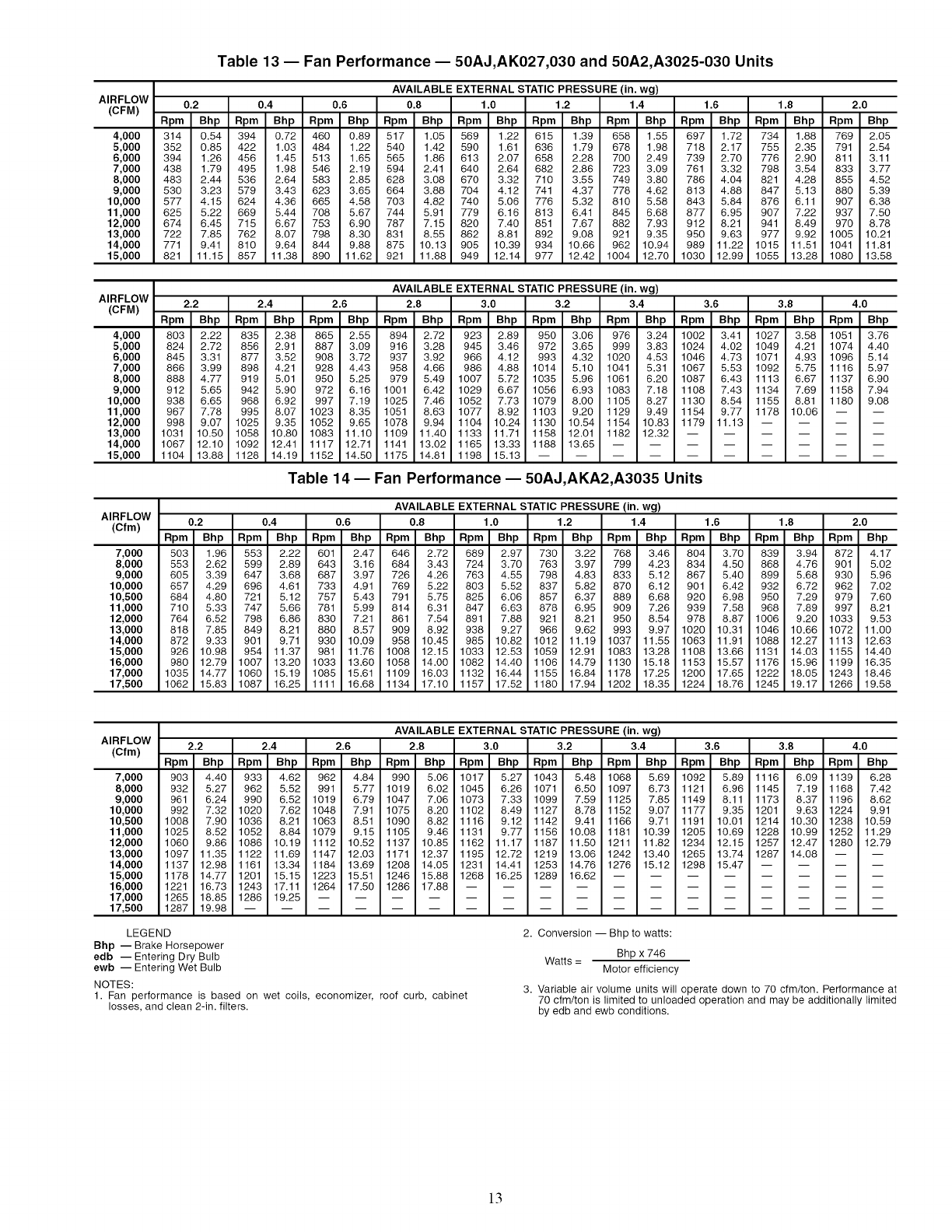
AIRFLOW
(CFM)
4,000
5,000
6,000
7,000
8,000
9,000
10,000
11,000
12,000
13,000
14,000
15,000
AIRFLOW
(CFM)
4,000
5,000
6,000
7,000
8,000
9,000
10,000
11,000
12,000
13,000
14,000
15,000
AIRFLOW
(Cfm)
7,000
8,000
9,000
10,000
10,500
11,000
12,000
13,000
14,000
15,000
16,000
17,000
17,500
Table 13 -- Fan Performance -- 50AJ,AK027,030 and 50A2,A3025-030 Units
AVAILABLE EXTERNAL STATIC PRESSURE (in. wg)
0.2 0.4 0.6 0.8 1.0 1.2 1.4 1.6 1.8 2.0
Rpm Bhp Rpm Bhp Rpm Bhp Rpm Bhp Rpm Bhp Rpm Bhp Rpm Bhp Rpm Bhp Rpm Bhp Rpm Bhp
314 0.54 394 0.72 460 0.89 517 1.05 569 1.22 615 1.39 658 1.55 697 1.72 734 1.88 769 2.05
352 0.85 422 1.03 484 1.22 540 1.42 590 1.61 636 1.79 678 1.98 718 2.17 755 2.35 791 2.54
394 1.26 456 1.45 513 1.65 565 1.86 613 2.07 658 2.28 700 2.49 739 2.70 776 2.90 811 3.11
438 1.79 495 1.98 546 2.19 594 2.41 640 2.64 682 2.86 723 3.09 761 3.32 798 3.54 833 3.77
483 2.44 536 2.64 583 2.85 628 3.08 670 3.32 710 3.55 749 3.80 786 4.04 821 4.28 855 4.52
530 3.23 579 3.43 623 3.65 664 3.88 704 4.12 741 4.37 778 4.62 813 4.88 847 5.13 880 5.39
577 4.15 624 4.36 665 4.58 703 4.82 740 5.06 776 5.32 810 5.58 843 5.84 876 6.11 907 6.38
625 5.22 669 5.44 708 5.67 744 5.91 779 6.16 813 6.41 845 6.68 877 6.95 907 7.22 937 7.50
674 6.45 715 6.67 753 6.90 787 7.15 820 7.40 851 7.67 882 7.93 912 8.21 941 8.49 970 8.78
722 7.85 762 8.07 798 8.30 831 8.55 862 8.81 892 9.08 921 9.35 950 9.63 977 9.92 1005 10.21
771 9.41 810 9.64 844 9.88 875 10.13 905 10.39 934 10.66 962 10.94 989 11.22 1015 11.51 1041 11.81
821 11.15 857 11.38 890 11.62 921 11.88 949 12.14 977 12.42 1004 12.70 1030 12.99 1055 13.28 1080 13.58
AVAILABLE EXTERNAL STATIC PRESSURE (in. wg)
2.2 2.4 2.6 2.8 3.0 3.2 3.4 3.6 3.8 4.0
Rpm Bhp Rpm Bhp Rpm Bhp Rpm Bhp Rpm Bhp Rpm Bhp Rpm Bhp Rpm Bhp Rpm Bhp Rpm Bhp
803 2.22 835 2.38 865 2.55 894 2.72 923 2.89 950 3.06 976 3.24 1002 3.41 1027 3.58 1051 3.76
824 2.72 856 2.91 887 3.09 916 3.28 945 3.46 972 3.65 999 3.83 1024 4.02 1049 4.21 1074 4.40
845 3.31 877 3.52 908 3.72 937 3.92 966 4.12 993 4.32 1020 4.53 1046 4.73 1071 4.93 1096 5.14
866 3.99 898 4.21 928 4.43 958 4.66 986 4.88 1014 5.10 1041 5.31 1067 5.53 1092 5.75 1116 5.97
888 4.77 919 5.01 950 5.25 979 5.49 1007 5.72 1035 5.96 1061 6.20 1087 6.43 1113 6.67 1137 6.90
912 5.65 942 5.90 972 6.16 1001 6.42 1029 6.67 1056 6.93 1083 7.18 1108 7.43 1134 7.69 1158 7.94
938 6.65 968 6.92 997 7.19 1025 7.46 1052 7.73 1079 8.00 1105 8.27 1130 8.54 1155 8.81 1180 9.08
967 7.78 995 8.07 1023 8.35 1051 8.63 1077 8.92 1103 9.20 1129 9.49 1154 9.77 1178 10.06 -- --
998 9.07 1025 9.35 1052 9.65 1078 9.94 1104 10.24 1130 10.54 1154 10.83 1179 11.13 ....
1031 10.50 1058 10.80 1083 11.10 1109 11.40 1133 11.71 1158 12.01 1182 12.32 ......
1067 12.10 1092 12.41 1117 12.71 1141 13.02 1165 13.33 1188 13.65 ........
1104 13.88 1128 14.19 1152 14.50 1175 14.81 1198 15.13 ..........
Table 14- Fan Performance- 50AJ,AKA2,A3035 Units
AVAILABLE EXTERNAL STATIC PRESSURE (in. wg)
0.2 0.4 0.6 0.8 1.0 1.2 1.4 1.6 1.8 2.0
Rpm Bhp Rpm Bhp Rpm Bhp Rpm Bhp Rpm Bhp Rpm Bhp Rpm Bhp Rpm Bhp Rpm Bhp Rpm Bhp
503 1.96 553 2.22 601 2.47 646 2.72 689 2.97 730 3.22 768 3.46 804 3.70 839 3.94 872 4.17
553 2.62 599 2.89 643 3.16 684 3.43 724 3.70 763 3.97 799 4.23 834 4.50 868 4.76 901 5.02
605 3.39 647 3.68 687 3.97 726 4.26 763 4.55 798 4.83 833 5.12 867 5.40 899 5.68 930 5.96
657 4.29 696 4.61 733 4.91 769 5.22 803 5.52 837 5.82 870 6.12 901 6.42 932 6.72 962 7.02
684 4.80 721 5.12 757 5.43 791 5.75 825 6.06 857 6.37 889 6.68 920 6.98 950 7.29 979 7.60
710 5.33 747 5.66 781 5.99 814 6.31 847 6.63 878 6.95 909 7.26 939 7.58 968 7.89 997 8.21
764 6.52 798 6.86 830 7.21 861 7.54 891 7.88 921 8.21 950 8.54 978 8.87 1006 9.20 1033 9.53
818 7.85 849 8.21 880 8.57 909 8.92 938 9.27 966 9.62 993 9.97 1020 10.31 1046 10.66 1072 11.00
872 9.33 901 9.71 930 10.09 958 10.45 985 10.82 1012 11.19 1037 11.55 1063 11.91 1088 12.27 1113 12.63
926 10.98 954 11.37 981 11.76 1008 12.15 1033 12.53 1059 12.91 1083 13.28 1108 13.66 1131 14.03 1155 14.40
980 12.79 1007 13.20 1033 13.60 1058 14.00 1082 14.40 1106 14.79 1130 15.18 1153 15.57 1176 15.96 1199 16.35
1035 14.77 1060 15.19 1085 15.61 1109 16.03 1132 16.44 1155 16.84 1178 17.25 1200 17.65 1222 18.05 1243 18.46
1062 15.83 1087 16.25 1111 16.68 1134 17.10 1157 17.52 1180 17.94 1202 18.35 1224 18.76 1245 19.17 1266 19.58
AIRFLOW
(Cfm)
7,000
8,000
9,000
10,000
10,500
11,000
12,000
13,000
14,000
15,000
16,000
17,000
17,500
AVAILABLE EXTERNAL STATIC PRESSURE (in. wg)
2.2 2.4 2.6 2.8 3.0 3.2 3.4 3.6 3.8 4.0
Rpm Bhp Rpm Bhp Rpm Bhp Rpm Bhp Rpm Bhp Rpm Bhp Rpm Bhp Rpm Bhp Rpm Bhp Rpm Bhp
903 4.40 933 4.62 962 4.84 990 5.06 1017 5.27 1043 5.48 1068 5.69 1092 5.89 1116 6.09 1139 6.28
932 5.27 962 5.52 991 5.77 1019 6.02 1045 6.26 1071 6.50 1097 6.73 1121 6.96 1145 7.19 1168 7.42
961 6.24 990 6.52 1019 6.79 1047 7.06 1073 7.33 1099 7.59 1125 7.85 1149 8.11 1173 8.37 1196 8.62
992 7.32 1020 7.62 1048 7.91 1075 8.20 1102 8.49 1127 8.78 1152 9.07 1177 9.35 1201 9.63 1224 9.91
1008 7.90 1036 8.21 1063 8.51 1090 8.82 1116 9.12 1142 9.41 1166 9.71 1191 10.01 1214 10.30 1238 10.59
1025 8.52 1052 8.84 1079 9.15 1105 9.46 1131 9.77 1156 10.08 1181 10.39 1205 10.69 1228 10.99 1252 11.29
1060 9.86 1086 10.19 1112 10.52 1137 10.85 1162 11.17 1187 11.50 1211 11.82 1234 12.15 1257 12.47 1280 12.79
1097 11.35 1122 11.69 1147 12.03 1171 12.37 1195 12.72 1219 13.06 1242 13.40 1265 13.74 1287 14.08 -- --
1137 12.98 1161 13.34 1184 13.69 1208 14.05 1231 14.41 1253 14.76 1276 15.12 1298 15.47 ....
1178 14.77 1201 15.15 1223 15.51 1246 15.88 1268 16.25 1289 16.62 ........
1221 16.73 1243 17.11 1264 17.50 1286 17.88 ............
1265 18.85 1286 19.25 ................
1287 19.98 ..................
LEGEND
Bhp -- Brake Horsepower
edb -- Entering Dry Bulb
ewb -- Entering Wet Bulb
NOTES:
1. Fan performance is based on wet coils, economizer, roof curb, cabinet
losses, and clean 2-in. filters.
2. Conversion -- Bhp to watts:
Bhp x 746
Watts = Motor efficiency
3. Variable air volume units will operate down to 70 cfm/ton. Performance at
70 cfm/ton is limited to unloaded operation and may be additionally limited
by edb and ewb conditions.
]3
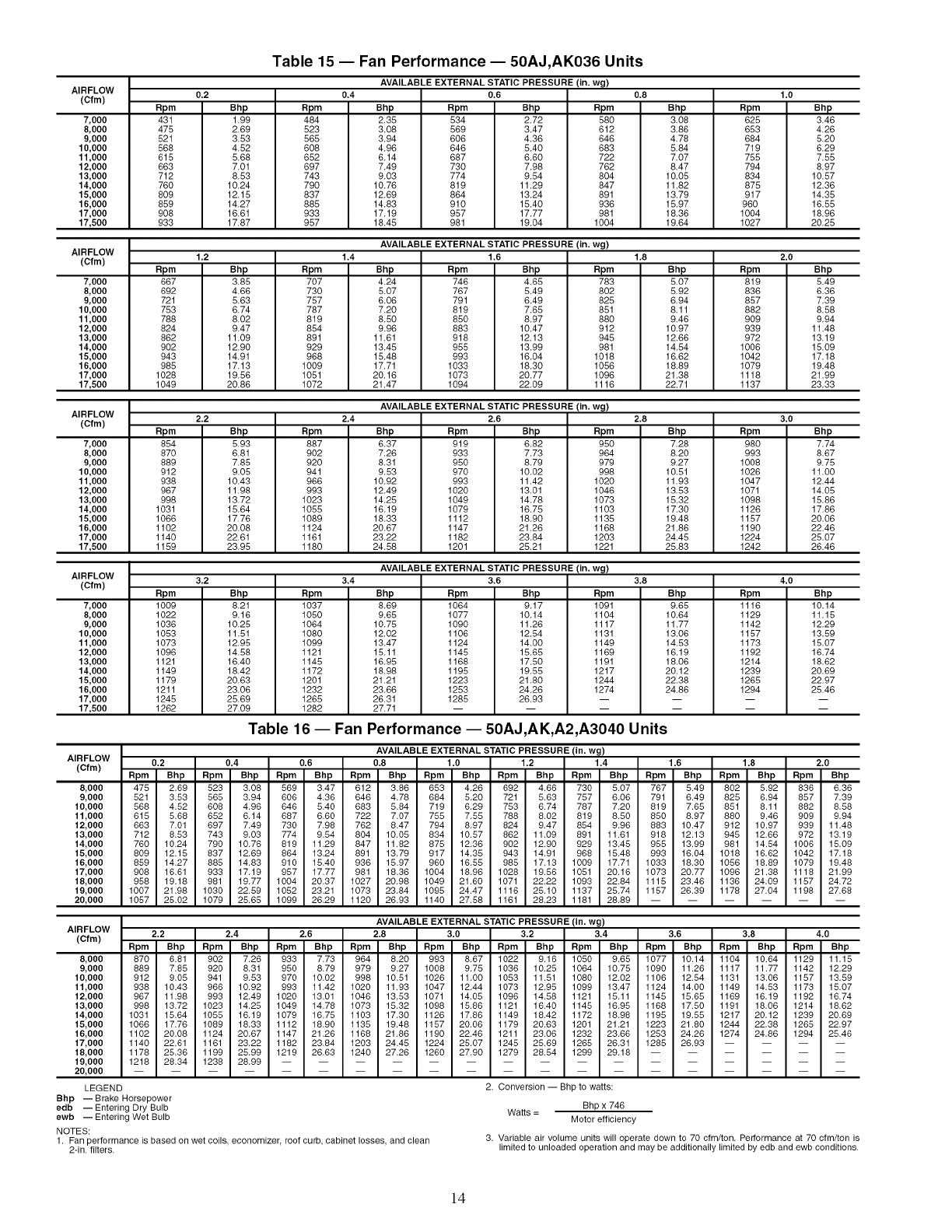
Table 15 -- Fan Performance- 50AJ,AK036 Units
AVAILABLE EXTERNAL STATIC PRESSURE (in. wg)
AIRFLOW 0.4 0.6 0.8 1.0
(cfm) 0.2
Rpm
431
475
521
566
615
663
712
76O
809
859
908
933
Bhp
199
2.69
3.53
4.52
5.68
7.01
8.53
10.24
12.15
14.27
16.61
17.87
7,000
8,000
9,000
10,000
11,000
12,000
13,000
14,000
15,000
16,000
17,000
17,500
Rpm
464
523
565
606
652
697
743
790
837
865
933
957
Bhp
2.35
306
394
496
614
749
903
1076
1269
14.83
17.19
18.45
Rpm
534
569
606
646
667
73O
774
819
864
910
957
961
Bhp
2.72
347
436
540
660
796
954
11.29
13.24
15.40
17.77
19.04
Rpm
560
612
646
663
722
762
8O4
847
891
936
961
1004
Bhp
3.08
3.86
4.78
5.84
7.07
8.47
10.05
11.62
13.79
15.97
18.36
19.64
Rpm
625
653
684
719
755
794
834
875
917
96O
1004
1027
Bhp
3.46
4.26
5.20
6.29
7.55
8.97
10.57
12.36
14.35
16.55
18.96
20.25
AIRFLOW AVAILABLE EXTERNAL STATIC PRESSURE (in. wg)
(Cfm) 1.4 1.6
7,000
8,000
9,000
10,000
11,000
12,000
13,000
14,000
15,000
16,000
17,000
17,500
1.2
Rpm
667
692
721
753
786
824
862
9O2
943
965
1026
1049
Bhp
3.85
4.66
5.63
6.74
8.02
9.47
11.09
12.90
14.91
17.13
19.56
20.86
Rpm
707
730
757
787
819
854
891
929
968
1009
1051
1072
Bhp
4.24
5.07
6.06
7.20
8.50
9.96
11.61
13.45
15.48
17.71
20.16
21.47
Rpm
746
767
791
819
850
863
918
955
993
1033
1073
1094
Bhp
4.65
5.49
6.49
7.65
8.97
10.47
12.13
13.99
16.04
18.30
20.77
22.09
Rpm
783
802
825
851
880
912
945
981
1018
1056
1096
1116
1.8
Bhp
5,07
5,92
6,94
8,11
9,46
10.97
12.66
14.54
16,62
18.89
21.38
22.71
Rpm
819
836
857
882
909
939
972
1006
1042
1079
1118
1137
2.0
Bhp
5,49
6,36
7,39
8.58
9.94
11.48
13.19
15.09
17.18
19.48
21.99
23.33
AVAILABLE EXTERNAL STATIC PRESSURE (in. wg)
AIRFLOW 2,4 2,6
(cfm)
7,000
8,000
9,000
10,000
11,000
12,000
13,000
14,000
15,000
16,000
17,000
17,500
2.2
Rpm
854
87O
889
912
936
967
996
1031
1066
1102
1140
1159
Bhp
5.93
6.81
7.85
9.05
10.43
11.98
13.72
15.64
17.76
20.08
22.61
23.95
Rpm
867
9O2
92O
941
966
993
1023
1055
1069
1124
1161
1180
Bhp
6.37
7.26
8.31
9.53
10.92
12.49
14.25
16.19
18.33
20.67
23.22
24.58
Rpm
919
933
95O
97O
993
1020
1049
1079
1112
1147
1182
1201
Bhp
6.82
7.73
8.79
10.02
11.42
13.01
14.78
16.75
18.90
21.26
23.84
25.21
Rpm
95O
964
979
996
1020
1046
1073
1103
1135
1166
1203
1221
2.8
Bhp
726
820
927
10.51
11.93
13.53
15.32
17.30
19.46
21.66
24.45
25.63
Rpm
98O
993
1008
1026
1047
1071
1098
1126
1157
1190
1224
1242
3.0
Bhp
7.74
8.67
9.75
11.00
12.44
14.05
15.86
17,66
20.06
22,46
25.07
26,46
AVAILABLE EXTERNAL STATIC PRESSURE (in. wg)
AIRFLOW 3.4 3.6
(Cfm)
7,000
8,000
9,000
10,000
11,000
12,000
13,000
14,000
15,000
16,000
17,000
17,500
3.2
Rpm
1009
1022
1036
1053
1073
1096
1121
1149
1179
1211
1245
1262
Bhp
8.21
9.16
10.25
11.51
12.95
14.58
16.40
18.42
20.63
23.06
25.69
27.09
Rpm
1037
1050
1064
1080
1099
1121
1145
1172
1201
1232
1265
1282
Bhp
8.69
9.65
10.75
12.02
13.47
15.11
16.95
18.98
21.21
23.66
26.31
27.71
Rpm
1064
1077
1090
1106
1124
1145
1166
1195
1223
1253
1285
Bhp
9.17
10.14
11.26
12.54
14.00
15.65
17.50
19.55
21.80
24.26
26.93
Rpm
1091
1104
1117
1131
1149
1169
1191
1217
1244
1274
3.8
Bhp
9.65
10.64
11.77
13.06
14.53
16.19
18.06
20.12
22.38
24.86
Rpm
1116
1129
1142
1157
1173
1192
1214
1239
1265
1294
4.0
Bhp
10.14
11.15
12.29
13.59
15.07
16.74
18.62
20.69
22.97
25.46
Table 16- Fan Performance- 50AJ,AK,A2,A3040 Units
AVAILABLE EXTERNAL STATIC PRESSURE (in. wg)
AIRFLOW 0.2 0.4 0.6 0.8 1.0 1.2 1.4 1.6 1.8 2.0
(Cfm)
8,000
9,000
10,000
11,000
12,000
13,000
14,000
15,000
16,000
17,000
18,000
19,000
20,000
Rpm Bhp Rpm Bhp Rpm Bhp Rpm Bhp Rpm Bhp Rpm Bhp Rpm Bhp Rpm Bhp Rpm Bhp Rpm Bhp
475 2,69 523 3.08 569 3.47 612 3.86 653 4.26 692 4.66 730 5.07 767 5.49 802 5.92 836 6.36
521 3.53 565 3.94 606 4.36 646 4.78 684 5.20 721 5.63 757 6.06 791 6.49 825 6.94 857 7.39
568 4.52 608 4.96 646 5.40 683 5.84 719 6.29 753 6.74 787 7.20 819 7.65 851 8.11 882 8.58
615 5.68 652 6.14 687 6.60 722 7.07 755 7.55 788 8.02 819 8.50 850 8.97 880 9.46 909 9.94
663 7.01 697 7.49 730 7.98 762 8.47 794 8.97 824 9.47 854 9.96 883 10.47 912 10.97 939 11.48
712 8.53 743 9.03 774 9.54 804 10.05 834 10.57 862 11.09 891 11.61 918 12.13 945 12.66 972 13.19
760 10.24 790 10.76 819 11.29 847 11.82 875 12.36 902 12.90 929 13.45 955 13.99 981 14.54 1006 15.09
809 12.15 837 12.69 864 13.24 891 13.79 917 14.35 943 14.91 968 15.48 993 16.04 1018 16.62 1042 17.18
859 14.27 885 14.83 910 15.40 936 15.97 960 16.55 985 17.13 1009 17.71 1033 18.30 1056 18.89 1079 19.48
908 16.61 933 17.19 957 17.77 981 18.36 1004 18.96 1028 19.56 1051 20.16 1073 20.77 1096 21.38 1118 21.99
958 19.18 981 19.77 1004 20.37 1027 20.98 1049 21.60 1071 22.22 1093 22.84 1115 23.46 1136 24.09 1157 24.72
1007 21.98 1030 22.59 1052 23.21 1073 23.84 1095 24.47 1116 25.10 1137 25.74 1157 26.39 1178 27.04 1198 27.68
1057 25.02 1079 25.65 1099 26.29 1120 26.93 1140 27.58 1161 28.23 1181 28.89 ......
AIRFLOW
(Cfm)
8,000
9,000
10,000
11,000
12,000
13,000
14,000
15,000
16,000
17,000
18,000
19,000
20,000
LEGEND
Bhp -- Brake Horsepower
edb -- Entering Dry Bulb
ewb -- Entering Wet Bulb
NOTES:
1. Fan performance is based on wet coils economizer roof curb, cabinet losses and clean
2-in. filters.
AVAILABLE EXTERNAL STATIC PRESSURE (in. wg)
2.2 2.4 2.6 2.8 3.0 3.2 3.4 3.6 3.8 4.0
Rpm Bhp Rpm Bhp Rpm Bhp Rpm Bhp Rpm Bhp Rpm Bhp Rpm Bhp Rpm Bhp Rpm Bhp Rpm Bhp
870 6.81 902 726 933 7.73 964 8.20 993 867 1022 9.16 1050 965 1077 10.14 1104 10.64 1129 1115
889 7.85 920 8.31 950 8.79 979 9.27 1008 9.75 1036 10.25 1064 10.75 1090 11.26 1117 11.77 1142 12.29
912 9.05 941 9.53 970 10.02 998 10.51 1026 11.00 1053 11.51 1080 12.02 1106 12.54 1131 13,06 1157 13.59
938 10.43 966 10.92 993 11.42 1020 11.93 1047 12.44 1073 12.95 1099 13.47 1124 14.00 1149 14.53 1173 15.07
967 11.98 993 12.49 1020 13.01 1046 13.53 1071 14.05 1096 14.58 1121 15.11 1145 15.65 1169 16.19 1192 16.74
998 13.72 1023 14.25 1049 14.78 1073 15.32 1098 15.86 1121 16.40 1145 16.95 1168 17.50 1191 18.06 1214 18.62
1031 15.64 1055 16.19 1079 16.75 1103 17.30 1126 17.86 1149 18.42 1172 18.98 1195 19.55 1217 20.12 1239 20.69
1066 17.76 1089 18.33 1112 18,90 1135 19.48 1157 20.06 1179 20.63 1201 21.21 1223 21.80 1244 22.38 1265 22.97
1102 20.08 1124 20.67 1147 21.26 1168 21.86 1190 22.46 1211 23.06 1232 23.66 1253 24.26 1274 24.86 1294 25.46
1140 22.61 1161 23.22 1182 23.84 1203 24.45 1224 25.07 1245 25.69 1265 26.31 1285 26.93 ....
1178 25.36 1199 25.99 1219 26.63 1240 27.26 1260 27.90 1279 28.54 1299 29.18 ......
1218 28.34 1238 28.99 ................
2. Conversion -- Bhp to watts:
Bhp x 746
Watts = Motor efficiency
3. Variable air volume units will operate down to 70 cfm/ton. Performance at 70 cfm/ton is
limited to unloaded operation and may be additionally limited by edb and ewb conditions.
14
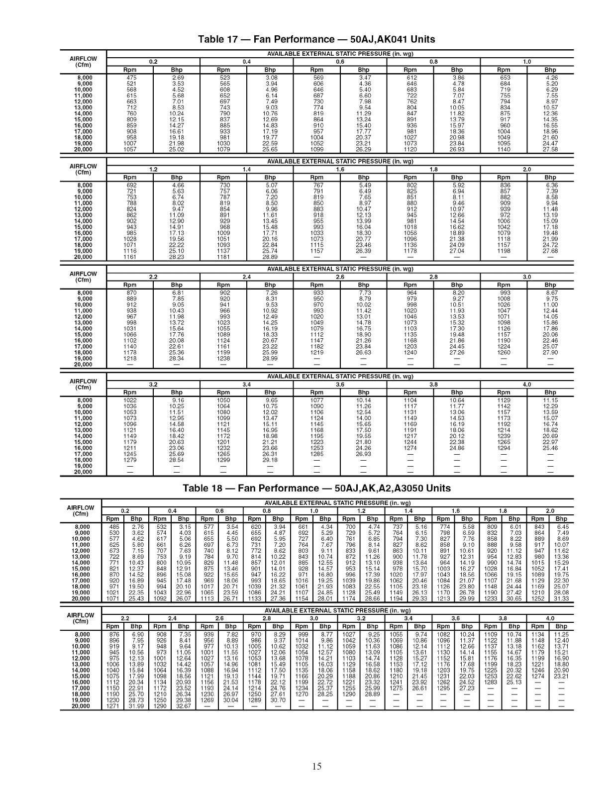
Table 17 -- Fan Performance -- 50AJ,AK041 Units
AVAILABLE EXTERNAL STATIC PRESSURE (in. wg)
AIRFLOW 0.2 0.4 0.6 0.8
(Cfm) Rpm
475
521
568
615
663
712
760
809
859
908
958
1007
1057
Bhp
2.69
3.53
4.52
5.68
7.01
8.53
10.24
12.15
14.27
16.61
19.18
21.98
25.02
8,000
9,000
10,000
11,000
12,000
13,000
14,000
15,000
16,000
17,000
18,000
19,000
20,000
Rpm
523
565
6O8
652
697
743
79O
837
865
933
961
1030
1079
Bhp
3.06
3.94
4.96
6.14
7.49
9.03
10.76
12.69
14.83
17.19
19.77
22.59
25.65
Rpm
569
6O6
646
667
73O
774
819
864
910
957
1004
1052
1099
Bhp
3.47
4.36
5.40
6.60
7.96
9.54
11.29
13.24
15.40
17.77
20.37
23.21
26.29
Rpm
612
646
663
722
762
8O4
847
891
936
981
1027
1073
1120
AVAILABLE EXTERNAL STATIC PRESSURE (in. wg)
AIRFLOW
(Cfm) 1.2 1.4 1.6
Rpm
692
721
753
786
824
862
9O2
943
985
1026
1071
1116
1161
8,000
9,000
10,000
11,000
12,000
13,000
14,000
15,000
16,000
17,000
18,000
19,000
20,000
Bhp
4.66
5.63
6.74
8.02
9.47
11.09
12.90
14.91
17.13
19.56
22.22
25.10
28.23
Rpm
73O
757
787
819
854
891
929
966
1009
1051
1093
1137
1181
Bhp
5.07
6.06
7.20
8.50
9.96
11.61
13.45
15.46
17.71
20.16
22.84
25.74
28.89
Rpm
767
791
819
85O
863
918
955
993
1033
1073
1115
1157
Bhp
5.49
6.49
7.65
8.97
10.47
12.13
13.99
16.04
18.30
20.77
23.46
26.39
Rpm
8O2
825
851
86O
912
945
961
1018
1056
1096
1136
1178
AVAILABLE EXTERNAL STATIC PRESSURE (in. wg)
AIRFLOW
(Cfm) 2.2 2,4 2,6
Rpm
87O
889
912
938
967
998
1031
1066
1102
1140
1178
1218
8,000
9,000
10,000
11,000
12,000
13,000
14,000
15,000
16,000
17,000
18,000
19,000
20,000
Bhp
6.81
7.85
9.05
10.43
11.98
13.72
15.64
17.76
20.08
22.61
25.36
28.34
Bhp
3.66
4.78
5.84
7.07
6.47
10.05
11.62
13.79
15.97
18.36
20.96
23.64
26.93
Rpm
9O2
92O
941
966
993
1023
1055
1089
1124
1161
1199
1238
Bhp
7.26
8.31
9.53
10.92
12.49
14.25
16.19
18.33
20.67
23.22
25.99
28.99
Rpm
933
95O
97O
993
1020
1049
1079
1112
1147
1182
1219
Bhp
7.73
8.79
10.02
11.42
13.01
14.78
16.75
18.90
21.26
23.84
26.63
Rpm
964
979
996
1020
1046
1073
1103
1135
1166
1203
1240
AVAILABLE EXTERNAL STATIC PRESSURE (in. wg)
AIRFLOW
(Cfm) 3.2 3.4 3.6
1.8
Bhp
5.92
6.94
8.11
9.46
10.97
12.66
14.54
16.62
18,89
21.38
24.09
27.04
Rpm
1022
1036
1053
1073
1096
1121
1149
1179
1211
1245
1279
8,000
9,000
10,000
11,000
12,000
13,000
14,000
15,000
16,000
17,000
18,000
19,000
20,000
Bhp
9.16
10.25
11.51
12.95
14.58
16.40
18.42
20.63
23.06
25.69
28.54
Rpm
1050
1064
1080
1099
1121
1145
1172
1201
1232
1265
1299
Bhp
9.65
10.75
12.02
13.47
15.11
16.95
18.98
21.21
23.66
26.31
29.18
Rpm
1077
1090
1106
1124
1145
1166
1195
1223
1253
1285
2.8
Bhp
820
927
10.51
11.93
13.53
15.32
17.30
19.46
21.66
24.45
27.26
Bhp
10.14
11.26
12.54
14.00
15.65
17.50
19.55
21.80
24.26
26.93
Rpm
1104
1117
1131
1149
1169
1191
1217
1244
1274
3.8
Bhp
10.64
11.77
13.06
14.53
16.19
18.06
20.12
22.36
24.86
Table 18- Fan Performance- 50AJ,AK,A2,A3050 Units
AIRFLOW
(Cfm)
8,000
9,000
10,000
11,000
12,000
13,000
14,000
15,000
16,000
17,000
18,000
19,000
20,000
AIRFLOW
(Cfm)
8,000
9,000
10,000
11,000
12,000
13,000
14,000
15,000
16,000
17,000
18,000
19,000
20,000
1.0
Rpm
653
664
719
755
794
834
875
917
96O
1004
1049
1095
1140
2.0
Rpm
836
857
862
909
939
972
1006
1042
1079
1118
1157
1198
3.0
Rpm
993
1008
1026
1047
1071
1098
1126
1157
1190
1224
1260
4,0
Rpm
1129
1142
1157
1173
1192
1214
1239
1265
1294
Bhp
4.26
5.20
6.29
7.55
8.97
10.57
12.36
14.35
16.55
18.96
21.60
24.47
27.58
Bhp
6.36
7.39
8.58
9.94
11.48
13.19
15.09
17.18
19.48
21.99
24.72
27.68
Bhp
8.67
9.75
11.00
12.44
14.05
15.86
17.86
20.06
22.46
25.07
27.90
Bhp
11.15
12.29
13.59
15.07
16.74
18.62
20.69
22.97
25.46
AVAILABLE EXTERNAL STATIC PRESSURE (in. wg)
0.2 0.4 0.6 0.8 1.0 1.2 1.4 1.6 1.8 2.0
Rpm Bhp Rpm Bhp Rpm Bhp Rpm Bhp Rpm Bhp Rpm Bhp Rpm Bhp Rpm Bhp Rpm Bhp Rpm Bhp
485 2,76 532 315 577 3.54 620 3.94 661 434 700 4.74 737 516 774 5.58 809 6.01 843 645
530 3.62 574 4.03 615 4.45 655 4.87 692 5.29 729 5.72 764 6.15 798 6.59 832 7.03 864 7.49
577 4.62 617 5.06 655 5.50 692 5.95 727 6.40 761 6.85 794 7.30 827 7.76 858 8.22 889 8.69
625 5.80 661 6.26 697 6.73 731 7.20 764 7.67 796 8.14 827 8.62 858 9.10 888 9.58 917 10.07
673 7.15 707 7.63 740 8.12 772 8.62 803 9.11 833 9.61 863 10.11 891 10.61 920 11.12 947 11.62
722 8.69 753 9.19 784 9.70 814 10.22 843 10.74 872 11.26 900 11.78 927 12.31 954 12.83 980 13.36
771 10.43 800 10.95 829 11.48 857 12.01 885 12.55 912 13.10 938 13.64 964 14.19 990 14.74 1015 15.29
821 12.37 848 12.91 875 13.46 901 14.01 928 14.57 953 15.14 978 15.70 1003 16.27 1028 16.84 1052 17.41
870 14.52 896 15.08 922 15.65 947 16.22 971 16.80 996 17.39 1020 17.97 1043 18.56 1066 19.15 1089 19.75
920 16.89 945 17.48 969 18.06 993 18.65 1016 19.25 1039 19.86 1062 20.46 1084 21.07 1107 21.68 1129 22.30
971 19.50 994 20.10 1017 20.71 1039 21.32 1061 21.93 1083 22.55 1108 23.18 1126 23.80 1148 24.44 1169 25.07
1021 22.35 1043 22.96 1068 23.59 1086 24.21 1107 24.85 1128 25.49 1149 26.13 1170 26.78 1190 27.42 1210 28.08
1071 25.43 1092 26.07 1113 26.71 1133 27.36 1154 28.01 1174 28.66 1194 29.33 1213 29.99 1233 30.65 1252 31.33
AVAILABLE EXTERNAL STATIC PRESSURE (in. wg)
2.2 2.4 2,6 2.8 3.0 3.2 3.4 3.6 3.8 4.0
Rpm Bhp Rpm Bhp Rpm Bhp Rpm Bhp Rpm Bhp Rpm Bhp Rpm Bhp Rpm Bhp Rpm Bhp Rpm Bhp
876 6.90 908 735 939 7.82 970 8.29 999 8,77 1027 9.25 1055 974 1082 10.24 1109 10.74 1134 11.25
896 7.95 926 8.41 956 8.89 986 9.37 1014 9.86 1042 10.36 1069 10.86 1096 11.37 1122 11.88 1148 12.40
919 9.17 948 9.64 977 10.13 1005 10.62 1032 11.12 1059 11.63 1086 12.14 1112 12.66 1137 13,18 1162 13.71
945 10.56 973 11.05 1001 11.58 1027 12.06 1054 12.87 1080 13,09 1105 13.61 1130 14.14 1155 14.67 1179 15.21
975 12,13 1001 12.64 1027 13.16 1053 13.68 1078 14.21 1103 14.74 1128 15.27 1152 15.81 1176 16.35 1199 16.90
1006 13.89 1032 14.42 1057 14.96 1081 15.49 1108 16.03 1129 16.58 1153 17.12 1176 17.68 1199 18.23 1221 18.80
1040 15.84 1064 16.39 1088 16.94 1112 17.80 1138 18.06 1158 18.62 1180 19.18 1203 19.75 1225 20.32 1246 20.90
1075 17.99 1098 18.56 1121 19.13 1144 19.71 1166 20.29 1188 20.86 1210 21.45 1231 22.03 1253 22.62 1274 23.21
1112 20.34 1134 20.93 1156 21.53 1178 22.12 1199 22.72 1221 23.32 1241 23.92 1262 24.52 1283 25.13 -- --
1150 22.91 1172 23.52 1193 24.14 1214 24.76 1234 25.37 1255 25.99 1275 26.61 1295 27.23 ....
1190 25.70 1210 26.34 1230 26.97 1250 27.61 1270 28.25 1290 28.89 ........
1230 28,73 1250 29.38 1269 30.04 1289 30.70 ............
1271 31.99 1290 32.67 ................
[5
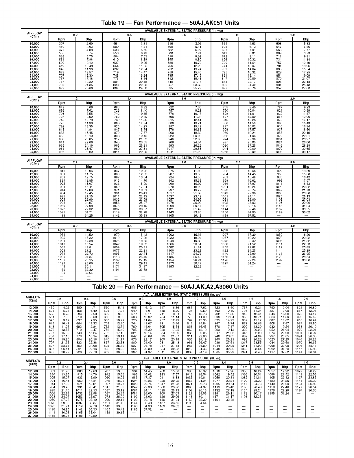
AIHI=LUW
(Cfm)
10,000
12,000
13,000
14,000
15,000
16,000
17,000
18,000
19,000
20,000
21,000
22,000
23,000
24,000
25,000
0.2
Rpm
397
45O
477
505
533
561
59O
619
648
678
707
737
767
797
827
0.4
Bhp Rpm
2.69 461
4.03 509
4.63 533
5.74 556
6.75 584
7,88 610
9,12 637
10.46 664
11.96 692
13.57 719
15.30 748
17,18 776
19.20 804
21.35 833
23.66 862
Table 19 -- Fan Performance -- 50AJ,AK051 Units
AVAILABLE EXTERNAL STATIC PRESSURE {in. w_l)
0.6
Bhp
3.31
4.71
5.55
6.49
7.53
8,68
9.95
11.33
12.84
14.47
16.24
18.14
20.18
22.36
24.68
Bpm
516
560
582
606
630
655
680
706
732
758
785
812
840
867
895
Bhp
3.96
5.41
6.27
7.24
8.32
9.50
10.79
12.20
13.74
15.40
17.19
19.11
21.17
23.38
25.72
Bpm
564
6O5
627
649
672
696
72O
744
769
795
621
647
673
9OO
927
AVAILABLE EXTERNAL STATIC PRESSURE (in. wg)
AIHI=LUW
tL.4)'^'m" 1.6 1.8
1.2
Rpm
649
666
706
727
748
77O
792
815
838
862
866
911
935
961
966
10,000
12,000
13,000
14,000
15,000
16,000
17,000
18,000
19,000
20,000
21,000
22,000
23,000
24,000
25,000
Bhp
6.06
7.62
8,55
9.59
10.73
11.98
13.35
14.84
16.45
18,19
20.05
22.06
24.19
26.47
28.89
Rpm
686
723
742
762
782
8O3
825
847
87O
893
917
940
965
989
1014
1.4
Bhp
6,82
8,40
9.35
10.40
11.56
12.84
14.23
15.74
17.37
19.13
21.02
23.05
25.21
27.51
29.95
Rpm
722
757
776
795
815
836
857
878
900
923
946
969
993
1017
1041
Bhp Rpm
7.60 755
9.21 790
10,17 808
11.24 827
12,41 846
13.71 866
15.12 887
16.65 908
18.30 930
20.08 952
22.00 974
24.04 997
26.23 1020
28.55 1044
31.02 1068
AVAILABLE EXTERNAL STATIC PRESSURE (in. wg)
AIHI=LUW
U.,i)'^'m" 2.2 2.6 2.8
2.4
Bhp
10.92
12.63
13.64
14.76
15.99
17.34
18.81
20.41
22.13
23.98
25.97
28.10
30.37
32.78
35.33
Bhp
10.06
11.75
12.75
13.85
15.07
16.41
17.86
19.45
21.15
22.99
24.97
27,08
29.32
31.71
34.25
10,000
12,000
13,000
14,000
15,000
16,000
17,000
18,000
19,000
20,000
21,000
22,000
23,000
24,000
25,000
Rpm
847
880
897
915
933
952
971
991
1011
1032
1053
1075
1097
1119
1142
Rpm
816
851
868
886
905
924
944
964
985
1006
1028
1050
1072
1095
1118
Bpm
875
907
924
942
960
978
997
1017
1037
1057
1078
1099
1121
1143
1165
Rpm
954
985
1001
1018
1035
1053
1071
1090
1109
1126
1148
1169
1190
Bhp Bpm
11.80 902
13.53 934
14.55 951
15.68 968
16.92 986
18.28 1004
19.77 1023
21.38 1042
23.12 1061
24.99 1081
26.99 1102
29.14 1123
31.42 1144
33.85 1166
36.42 1188
AIHPLUW
(Cfm)
10,000
12,000
13,000
14,000
15,000
16,000
17,000
18,000
19,000
20,000
21,000
22,000
23,000
24,000
25,000
AVAILABLEEXTERNALSTATICPRESSURE(in.w_)
3.2 3.4 3.6 3.8
AIHI=LUW
(Cfm)
Rpm
979
1010
1026
1042
1059
1077
1095
1113
1132
1151
1171
1191
12,000
14,000
15,000
16,000
17,000
18,000
19,000
20,000
21,000
22,000
23,000
24,000
25,000
26,000
27,000
Bhp
14.50
16.32
17,38
18,54
19.81
21.21
22.73
24.37
26,15
28.06
30.11
32.30
34.64
Bhp
15,42
17.28
18.35
19,52
20.81
22,21
23.74
25,40
27.19
29,11
31,17
33,38
Rpm
1003
1033
1049
1066
1082
1100
1117
1136
1154
1173
1193
Bhp
16.36
18.24
19,32
20,51
21,81
23,22
24,76
26.43
28,24
30.17
32,25
Rpm
1027
1057
1072
1088
1105
1122
1140
1158
1176
1195
0.8 1.0
Bhp
4.63
6.12
7.01
8.01
9.11
10.32
11.64
13.07
14.64
16.32
18.14
20.09
22.17
24.40
26.78
Bhp
8.40
10.04
11.01
12.09
13.28
14.59
16.02
17.57
19.24
21.04
22.98
25.05
27.25
29.60
32.09
Bhp
12.68
14.45
15.48
16.62
17.87
19.25
20.74
22.36
24.11
26.00
28.02
30.18
32.48
34.93
37.52
Bpm
6O8
647
668
689
711
734
757
781
805
829
854
879
9O5
931
957
Bhp
5.33
6.86
7.77
8.79
9.91
11.14
12.49
13.96
15.54
17.25
19.09
21.07
23.18
25.43
27.83
Bhp
17.30
19,22
20,32
21.52
22,82
24.25
25.80
27.48
29.29
31.24
Rpm
787
821
839
857
876
896
916
937
958
979
1001
1024
1046
1070
1093
2.0
Bhp
9.23
10,89
11.87
12,96
14.17
15,49
16.94
18,50
20.19
22,01
23.97
26.06
28,28
30,65
33,17
3.0
Bpm Bhp
929 13.59
960 15.38
976 16.42
993 17.57
1011 18.83
1029 20.22
1047 21.73
1066 23.36
1085 25.13
1105 27.03
1126 29.06
1146 31.24
1167 33.55
1189 36.02
4.0
Rpm Bhp
1050 18,26
1079 20,22
1095 21.32
1111 22,53
1127 23.85
1144 25.29
1161 26.85
1179 28,54
1197 30,36
Table 20 -- Fan Performance -- 50AJ,AK,A2,A3060 Units
AVAILABLE EXTERNAL STATIC PRESSURE (in. wg)
0.2 0.4 0.6 0.8 1.0 1.2 1.4 1.6 1.8 2.0
Rpm Bhp Rpm Bhp Rpm Bhp Rpm Bhp Rpm Bhp Rpm Bhp Rpm Bhp Rpm Bhp Rpm Bhp Rpm Bhp
450 4.02 509 4.71 560 5.41 605 6.12 647 6.86 686 7.62 723 8.40 757 9,21 790 10.04 821 10.89
505 5.74 558 6.49 606 7.24 649 8,01 689 8.79 727 9.59 762 10.40 795 11.24 827 12.09 857 12.96
533 6.75 584 7.53 630 8.32 672 9.11 711 9,91 748 10.73 782 11.56 815 12.41 846 13.28 876 14.17
561 7.88 610 8.68 655 9.50 696 10.32 734 11.14 770 11.98 803 12.84 836 13.71 866 14.59 896 15.49
590 9.12 637 9.95 680 10.79 720 11.64 757 12.49 792 13.35 825 14.23 857 15.12 887 16.02 916 16.94
619 10.48 664 11.33 706 12.20 744 13.07 781 13.96 815 14,84 847 15.74 878 16.65 908 17.57 937 18.50
648 11.96 692 12.84 732 13.74 769 14.64 805 15.54 838 16.45 870 17.37 900 18.30 930 19.24 958 20.19
678 13.57 719 14.47 758 15.40 795 16.32 829 17.25 862 18.19 893 19.13 923 20.08 952 21.04 979 22.01
707 15.30 748 16.24 785 17.19 821 18,14 854 19.09 886 20.05 917 21.02 946 22.00 974 22.98 1001 23.97
737 17.18 776 18.14 812 19,11 847 20.09 879 21.07 911 22.06 940 23.05 969 24.04 997 25.05 1024 26.06
767 19.20 804 20.18 840 21.17 673 22.17 905 23.18 935 24.19 965 25.21 993 26.23 1020 27,25 1046 28.28
797 21.35 833 22.36 867 23.38 900 24.40 931 25.43 961 26.47 989 27.51 1017 28,55 1044 29.60 1070 30.65
827 23.66 862 24.68 895 25.72 927 26,78 957 27.83 986 28.89 1014 29.95 1041 31.02 1068 32.09 1093 33.17
857 26.11 891 27.16 923 28.23 954 29.30 984 30.38 1012 31.46 1040 32.55 1066 33.64 1092 34.73 1117 35.83
888 28.72 920 29.79 952 30.88 982 31.97 1011 33.08 1038 34.19 1065 35.29 1091 36.40 1117 37.52 1141 38.64
AVAILABLE EXTERNAL STATIC PRESSURE (in. wg)
AIRFLOW
(Cfm) 2.2 2.4 2.6 2.8 3.0 3.2 3.4 3.6 3.8 4.0
12,000
14,000
15,000
16,000
17,000
18,000
19,000
20,000
21,000
22,000
23,000
24,000
25,000
26,000
27,000
20.22
22.53
23.85
25.29
26.85
28.54
30.36
]_d
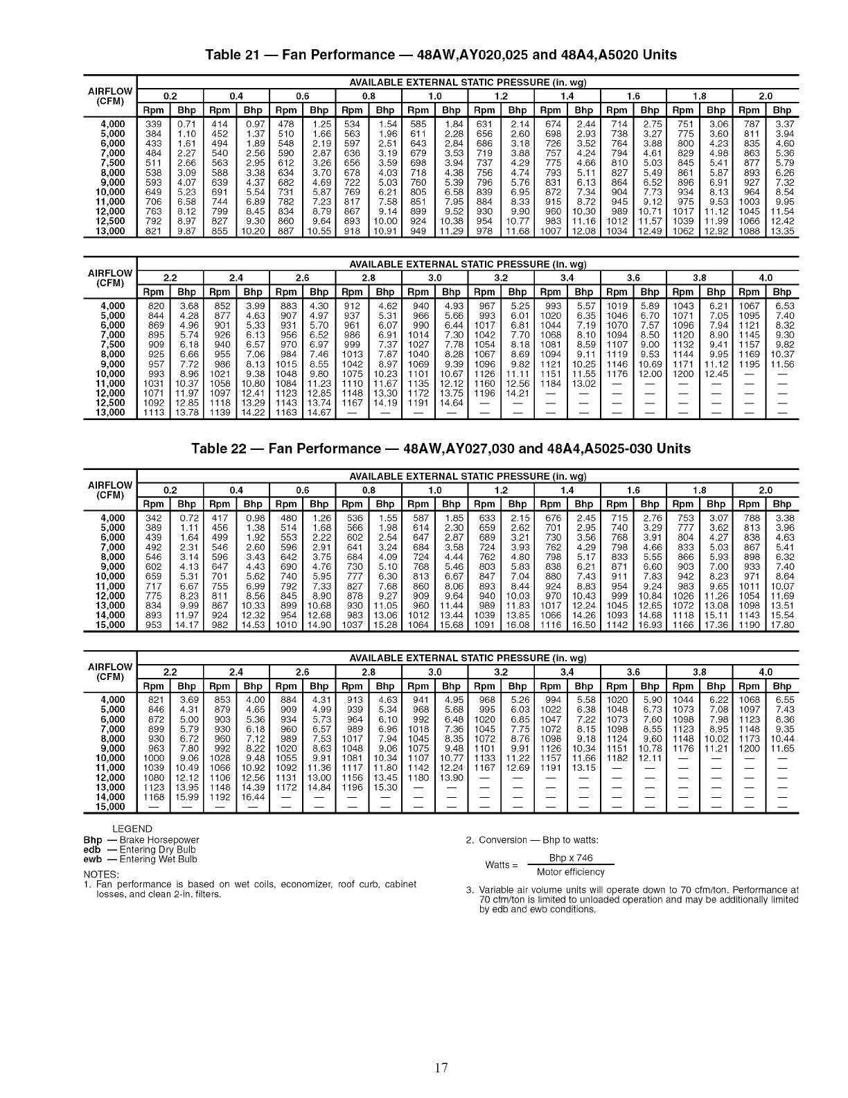
AIRFLOW
(CFM)
4,000
5,000
6,000
7,000
7,500
8,000
9,000
10,000
11,000
12,000
12,500
13,000
Table 21 -- Fan Performance -- 48AW,AY020,025 and 48A4,A5020 Units
AVAILABLE EXTERNAL STATIC PRESSURE (in. wg)
0.2 0.4 0.6 0.8 1.0 1.2 1.4 1.6 1.8 2.0
Rpm Bhp Rpm Bhp Rpm Bhp Rpm Bhp Rpm Bhp Rpm Bhp Rpm Bhp Rpm Bhp Rpm Bhp Rpm Bhp
339 0.71 414 0.97 478 1.25 534 1.54 585 1.84 631 2.14 674 2.44 714 2.75 751 3.06 787 3.37
384 1.10 452 1.37 510 1.66 563 1.96 611 2.28 656 2.60 698 2.93 738 3.27 775 3.60 811 3.94
433 1.61 494 1.89 548 2.19 597 2.51 643 2.84 686 3.18 726 3.52 764 3.88 800 4.23 835 4.60
484 2.27 540 2.56 590 2.87 636 3.19 679 3.53 719 3.88 757 4.24 794 4.61 829 4.98 863 5.36
511 2.66 563 2.95 612 3.26 656 3.59 698 3.94 737 4.29 775 4.66 810 5.03 845 5.41 877 5.79
538 3.09 588 3.38 634 3.70 678 4.03 718 4.38 756 4.74 793 5.11 827 5.49 861 5.87 893 6.26
593 4.07 639 4.37 682 4.69 722 5.03 760 5.39 796 5.76 831 6.13 864 6.52 896 6.91 927 7.32
649 5.23 691 5.54 731 5.87 769 6.21 805 6.58 839 6.95 872 7.34 904 7.73 934 8.13 964 8.54
706 6.58 744 6.89 782 7.23 817 7.58 851 7.95 884 8.33 915 8.72 945 9.12 975 9.53 1003 9.95
763 8.12 799 8.45 834 8.79 867 9.14 899 9.52 930 9.90 960 10.30 989 10.71 1017 11.12 1045 11.54
792 8.97 827 9.30 860 9.64 893 10.00 924 10.38 954 10.77 983 11.16 1012 11.57 1039 11.99 1066 12.42
821 9.87 855 10.20 887 10.55 918 10.91 949 11.29 978 11.68 1007 12.08 1034 12.49 1062 12.92 1088 13.35
AIRFLOW
(CFM)
4,000
5,000
6,000
7,000
7,500
8,000
9,000
10,000
11,000
12,000
12,500
13,000
AVAILABLE EXTERNAL STATIC PRESSURE (in. wg)
2.2 2.4 2.6 2.8 3.0 3.2 3.4 3.6 3.8 4.0
Rpm Bhp Rpm Bhp Rpm Bhp Rpm Bhp Rpm Bhp Rpm Bhp Rpm Bhp Rpm Bhp Rpm Bhp Rpm Bhp
820 3.68 852 3.99 883 4.30 912 4.62 940 4.93 967 5.25 993 5.57 1019 5.89 1043 6.21 1067 6.53
844 4.28 877 4.63 907 4.97 937 5.31 966 5.66 993 6.01 1020 6.35 1046 6.70 1071 7.05 1095 7.40
869 4.96 901 5.33 931 5.70 961 6.07 990 6.44 1017 6.81 1044 7.19 1070 7.57 1096 7.94 1121 8.32
895 5.74 926 6.13 956 6.52 986 6.91 1014 7.30 1042 7.70 1068 8.10 1094 8.50 1120 8.90 1145 9.30
909 6.18 940 6.57 970 6.97 999 7.37 1027 7.78 1054 8.18 1081 8.59 1107 9.00 1132 9.41 1157 9.82
925 6.66 955 7.06 984 7.46 1013 7.87 1040 8.28 1067 8.69 1094 9.11 1119 9.53 1144 9.95 1169 10.37
957 7.72 986 8.13 1015 8.55 1042 8.97 1069 9.39 1096 9.82 1121 10.25 1146 10.69 1171 11.12 1195 11.56
993 8.96 1021 9.38 1048 9.80 1075 10.23 1101 10.67 1126 11.11 1151 11.55 1176 12.00 1200 12.45 -- --
1031 10.37 1058 10.80 1084 11.23 1110 11.67 1135 12.12 1160 12.56 1184 13.02 ......
1071 11.97 1097 12.41 1123 12.85 1148 13.30 1172 13.75 1196 14.21 ........
1092 12.85 1118 13.29 1143 13.74 1167 14.19 1191 14.64 ..........
1113 13.78 1139 14.22 1163 14.67 ..............
AIRFLOW
(CFM)
4,000
5,000
6,000
7,000
8,000
9,000
10,000
11,000
12,000
13,000
14,000
15,000
Table 22 -- Fan Performance -- 48AW,AY027,030 and 48A4,A5025-030 Units
AVAILABLE EXTERNAL STATIC PRESSURE(in. wg)
0.2 0.4 0.6 0.8 1.0 1.2 1.4 1.6 1.8 2.0
Rpm Bhp Rpm Bhp Rpm Bhp Rpm Bhp Rpm Bhp Rpm Bhp Rpm Bhp Rpm Bhp Rpm Bhp Rpm Bhp
342 0.72 417 0.98 480 1.26 536 1.55 587 1.85 633 2.15 676 2.45 715 2.76 753 3.07 788 3.38
389 1.11 456 1.38 514 1.68 566 1.98 614 2.30 659 2.62 701 2.95 740 3.29 777 3.62 813 3.96
439 1.64 499 1.92 553 2.22 602 2.54 647 2.87 689 3.21 730 3.56 768 3.91 804 4.27 838 4.63
492 2.31 546 2.60 596 2.91 641 3.24 684 3.58 724 3.93 762 4.29 798 4.66 833 5.03 867 5.41
546 3.14 596 3.43 642 3.75 684 4.09 724 4.44 762 4.80 798 5.17 833 5.55 866 5.93 898 6.32
602 4.13 647 4.43 690 4.76 730 5.10 768 5.46 803 5.83 838 6.21 871 6.60 903 7.00 933 7.40
659 5.31 701 5.62 740 5.95 777 6.30 813 6.67 847 7.04 880 7.43 911 7.83 942 8.23 971 8.64
717 6.67 755 6.99 792 7.33 827 7.68 860 8.06 893 8.44 924 8.83 954 9.24 983 9.65 1011 10.07
775 8.23 811 8.56 845 8.90 878 9.27 909 9.64 940 10.03 970 10.43 999 10.84 1026 11.26 1054 11.69
834 9.99 867 10.33 899 10.68 930 11.05 960 11.44 989 11.83 1017 12.24 1045 12.65 1072 13.08 1098 13.51
893 11.97 924 12.32 954 12.68 983 13.06 1012 13.44 1039 13.85 1066 14.26 1093 14.68 1118 15.11 1143 15.54
953 14.17 982 14.53 1010 14.90 1037 15.28 1064 15.68 1091 16.08 1116 16.50 1142 16.93 1166 17.36 1190 17.80
AIRFLOW
(CFM)
4,000
5,000
6,000
7,000
8,000
9,000
10,000
11,000
12,000
13,000
14,000
15,000
AVAILABLE EXTERNAL STATIC PRESSURE (in. wg)
2.2 2.4 2.6 2.8 3.0 3.2 3.4 3.6 3.8 4.0
Rpm Bhp Rpm Bhp Rpm Bhp Rpm Bhp Rpm Bhp Rpm Bhp Rpm Bhp Rpm Bhp Rpm Bhp Rpm Bhp
821 3.69 853 4.00 884 4.31 913 4.63 941 4.95 968 5.26 994 5.58 1020 5.90 1044 6.22 1068 6.55
846 4.31 879 4.65 909 4.99 939 5.34 968 5.68 995 6.03 1022 6.38 1048 6.73 1073 7.08 1097 7.43
872 5.00 903 5.36 934 5.73 964 6.10 992 6.48 1020 6.85 1047 7.22 1073 7.60 1098 7.98 1123 8.36
899 5.79 930 6.18 960 6.57 989 6.96 1018 7.36 1045 7.75 1072 8.15 1098 8.55 1123 8.95 1148 9.35
930 6.72 960 7.12 989 7.53 1017 7.94 1045 8.35 1072 8.76 1098 9.18 1124 9.60 1148 10.02 1173 10.44
963 7.80 992 8.22 1020 8.63 1048 9.06 1075 9.48 1101 9.91 1126 10.34 1151 10.78 1176 11.21 1200 11.65
1000 9.06 1028 9.48 1055 9.91 1081 10.34 1107 10.77 1133 11.22 1157 11.66 1182 12.11 ....
1039 10.49 1066 10.92 1092 11.36 1117 11.80 1142 12.24 1167 12.69 1191 13.15 ......
1080 12.12 1106 12.56 1131 13.00 1156 13.45 1180 13.90 ..........
1123 13.95 1148 14.39 1172 14.84 1196 15.30 ............
1168 15.99 1192 16.44 ................
LEGEND
Bhp -- Brake Horsepower
edb -- Entering Dry Bulb
ewb -- Entering Wet Bulb
NOTES:
1. Fan performance is based on wet coils, economizer, roof curb, cabinet
losses, and clean 2-in. filters.
2. Conversion -- Bhp to watts:
Bhp x 746
Watts = Motor efficiency
3. Variable air volume units will operate down to 70 cfm/ton. Performance at
70 cfm/ton is limited to unloaded operation and may be additionally limited
by edb and ewb conditions.
]7
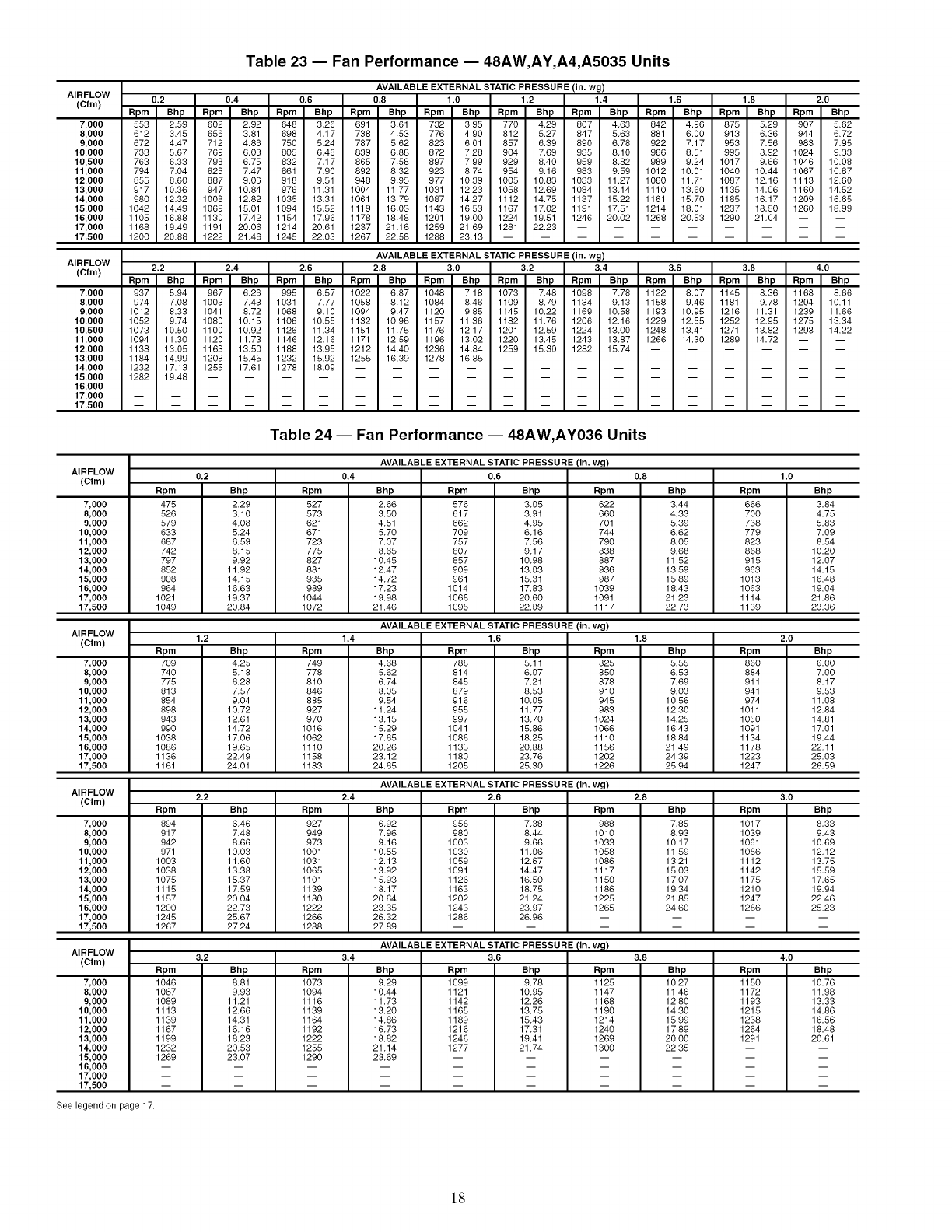
AIRFLOW
(Cfm)
7,000
8,000
9,000
10,000
10,500
11,000
12,000
13,000
14,000
15,000
16,000
17,000
17,500
AIRFLOW
(Of m)
7,000
8,000
9,000
10,000
10,500
11,000
12,000
13,000
14,000
15,000
16,000
17,000
17,500
Table 23 -- Fan Performance -- 48AW,AY,A4,A5035 Units
AVAILABLE EXTERNAL STATIC PRESSURE (in. wg)
0.2 0.4 0.6 0.8 1.0 1.2 1.4 1.6 1.8 2.0
Rpm Bhp Rpm Bhp Rpm Bhp Rpm Bhp Rpm Bhp Rpm Bhp Rpm Bhp Rpm Bhp Rpm Bhp Rpm Bhp
553 2,59 602 2.92 648 3.26 691 361 732 3.95 770 4.29 807 463 842 4.96 875 529 907 5.62
612 3.45 656 3.81 698 4.17 738 4.53 776 4.90 812 5.27 847 5.63 881 6.00 913 6.36 944 6.72
672 4.47 712 4.86 750 5.24 787 5.62 823 6.01 857 6.39 890 6.78 922 7.17 953 7.56 983 7.95
733 5.67 769 6.08 805 6.48 839 6.88 872 7.28 904 7.69 935 8.10 966 8.51 995 8.92 1024 9.33
763 6.33 798 6.75 832 7.17 865 7.58 897 7.99 929 8.40 959 8.82 989 9.24 1017 9.66 1046 10.08
794 7.04 828 7.47 861 7.90 892 8.32 923 8.74 954 9.16 983 9.59 1012 10.01 1040 10.44 1067 10.87
855 8.60 887 9.06 918 9.51 948 9.95 977 10.39 1005 10.83 1033 11.27 1060 11.71 1087 12.16 1113 12.60
917 10.36 947 10.84 976 11.31 1004 11.77 1031 12.23 1058 12.69 1084 13.14 1110 13.60 1135 14.06 1160 14.52
980 12.32 1008 12.82 1035 13.31 1061 13.79 1087 14.27 1112 14.78 1137 18.22 1161 15.70 1185 16.17 1209 16.65
1042 14.49 1069 18.01 1094 15.52 1119 16.03 1143 16.53 1167 17.02 1191 17.81 1214 18.01 1237 18.80 1260 18.99
1105 16.88 1130 17.42 1154 17.96 1178 18.48 1201 19.00 1224 19.51 1246 20.02 1268 20.53 1290 21.04 -- --
1168 19.49 1191 20.06 1214 20.61 1237 21.16 1259 21.69 1281 22.23 ........
1200 20.88 1222 21.46 1245 22.03 1267 22.58 1288 23.13 ..........
AVAILABLE EXTERNAL STATIC PRESSURE(in. wg)
2.2 2.4 2,6 2.8 3.0 3.2 3.4 3.6 3.8 4.0
Rpm Bhp Rpm Bhp Rpm Bhp Rpm Bhp Rpm Bhp Rpm Bhp Rpm Bhp Rpm Bhp Rpm Bhp Rpm Bhp
937 5.94 967 6.26 995 6.57 1022 6.87 1048 7.18 1073 7.48 1098 7.78 1122 8.07 1145 8.36 1168 8.66
974 7.08 1003 7.43 1031 7.77 1058 8.12 1084 8,46 1109 8.79 1134 9.13 1158 9.46 1181 9.78 1204 10.11
1012 8.33 1041 8.72 1068 9.10 1094 9.47 1120 9.85 1148 10.22 1169 10.88 1193 10.95 1216 11.31 1239 11.66
1052 9.74 1080 10.15 1106 10.55 1132 10.96 1157 11.36 1182 11.76 1206 12.16 1229 12,55 1252 12.95 1275 13.34
1073 10.80 1100 10.92 1126 11.34 1151 11.78 1176 12.17 1201 12,89 1224 13.00 1248 13,41 1271 13.82 1293 14.22
1094 11.30 1120 11.73 1146 12.16 1171 12.59 1196 13.02 1220 13.45 1243 13.87 1266 14.30 1289 14.72 -- --
1138 13.05 1163 13.50 1188 13.95 1212 14.40 1236 14.84 1259 15.30 1282 15.74 ......
1184 14.99 1208 15.45 1232 15.92 1255 16.39 1278 16.85 ..........
1232 17.13 1255 17.61 1278 18.09 ..............
1282 19.48 ..................
Table 24 -- Fan Performance -- 48AW,AY036 Units
AVAILABLE EXTERNAL STATIC PRESSURE (in. wg)
AIRFLOW 0.2 0.4 0.6
(ctm)
7,000
8,000
9,000
10,000
11,000
12,000
13,000
14,000
15,000
16,000
17,000
17,500
Rpm
475
526
579
633
687
742
797
852
908
964
1021
1049
Bhp
2.29
3.10
4.08
5.24
6.59
8.15
9.92
11.92
14.15
16.63
19.37
20.84
Rpm
527
573
621
671
723
775
827
881
935
989
1044
1072
Bhp
2.66
3.50
4.51
5.70
7.07
8.65
10.45
12.47
14.72
17.23
19.98
21.46
Rpm
576
617
662
7O9
757
8O7
857
9O9
961
1014
1068
1095
Bhp
3.05
3.91
4.95
6.16
7.56
9.17
10.98
13.03
15.31
17.83
20.60
22.09
Rpm
622
66O
701
744
79O
838
887
936
987
1039
1091
1117
AIRFLOW AVAILABLE EXTERNAL STATIC PRESSURE (in. wg)
(Cfm) 1.2 1.4 1.6
7,000
8,000
9,000
10,000
11,000
12,000
13,000
14,000
15,000
16,000
17,000
17,500
Rpm
7O9
740
775
813
854
898
943
99O
1038
1086
1136
1161
Bhp
4.25
5.18
6.28
7.57
9.04
10.72
12.61
14.72
17.06
19.68
22.49
24.01
Rpm
749
778
810
846
885
927
97O
1016
1062
1110
1158
1183
Bhp
4.68
5.62
6.74
8.05
9.54
11.24
13.15
15.29
17.65
20.26
23.12
24.68
Rpm
788
814
845
879
916
955
997
1041
1086
1133
1180
1208
Bhp
5.11
6.07
7.21
8.53
10.05
11.77
13.70
15.86
18.25
20.88
23.76
28.30
Rpm
825
85O
878
910
945
983
1024
1066
1110
1156
1202
1226
0.8
Bhp
344
433
539
662
805
9.68
11.82
13.89
16.89
18.43
21.23
22.73
Rpm
666
7OO
738
779
823
868
915
963
1013
1063
1114
1139
AIRFLOW AVAILABLE EXTERNAL STATIC PRESSURE (in. wg)
(Cfm) 2.2 2,4 2,6
7,000
8,000
9,000
10,000
11,000
12,000
13,000
14,000
15,000
16,000
17,000
17,500
Rpm
894
917
942
971
1003
1038
1075
1115
1157
1200
1245
1267
Bhp
6.46
7.48
8.66
10.03
11.60
13.38
18.37
17.89
20.04
22.73
28.67
27.24
Rpm
927
949
973
1001
1031
1065
1101
1139
1180
1222
1266
1288
Bhp
6.92
7.96
9.16
10.88
12.13
13.92
18.93
18.17
20.64
23.38
26.32
27.89
1.8
Bhp
555
653
769
903
10.56
12.30
14.28
16.43
18,84
21.49
24.39
25.94
Rpm
86O
884
911
941
974
1011
1050
1091
1134
1178
1223
1247
Rpm
958
980
1003
1030
1059
1091
1126
1163
1202
1243
1286
Bhp
7.38
8.44
9.66
11.06
12.67
14.47
16.80
18.78
21.24
23.97
26.96
Rpm
988
1010
1033
1058
1086
1117
1150
1186
1228
1268
AIRFLOW AVAILABLE EXTERNAL STATIC PRESSURE (in. wg)
(Cfm) 3.2 3.4 3.6
7,000
8,000
9,000
10,000
11,000
12,000
13,000
14,000
15,000
16,000
17,000
17,500
Rpm
1046
1067
1089
1113
1139
1167
1199
1232
1269
2.8
Bhp
785
893
10.17
11.59
13.21
16.03
17.07
19.34
21.88
24.60
Rpm
1017
1039
1061
1086
1112
1142
1178
1210
1247
1286
Bhp
8.81
9.93
11.21
12.66
14.31
16.16
18.23
20.53
23.07
Rpm
1073
1094
1116
1139
1164
1192
1222
1255
1290
Bhp
9.29
10.44
11.73
13.20
14.86
16.73
18.82
21.14
23.69
Rpm
1099
1121
1142
1165
1189
1216
1246
1277
Bhp
9.78
10.95
12.26
13.75
15.43
17.31
19.41
21.74
Rpm
1125
1147
1168
1190
1214
1240
1269
1300
3.8
Bhp
10.27
11.46
12.80
14.30
16.99
17.89
20.00
22.38
Rpm
1150
1172
1193
1215
1238
1264
1291
1.0
Bhp
384
475
583
709
854
1020
1207
14.15
16.48
19.04
21.86
2336
2,0
Bhp
600
700
817
953
11 08
12.84
14.81
17.01
19.44
22.11
28.03
26.89
3.0
Bhp
8,33
9.43
10.69
12.12
13.78
18.89
17.68
19.94
22.46
28.23
4,0
Bhp
10.76
11.98
13.33
14.86
16.86
18.48
20.61
See legend on page 17.
[8
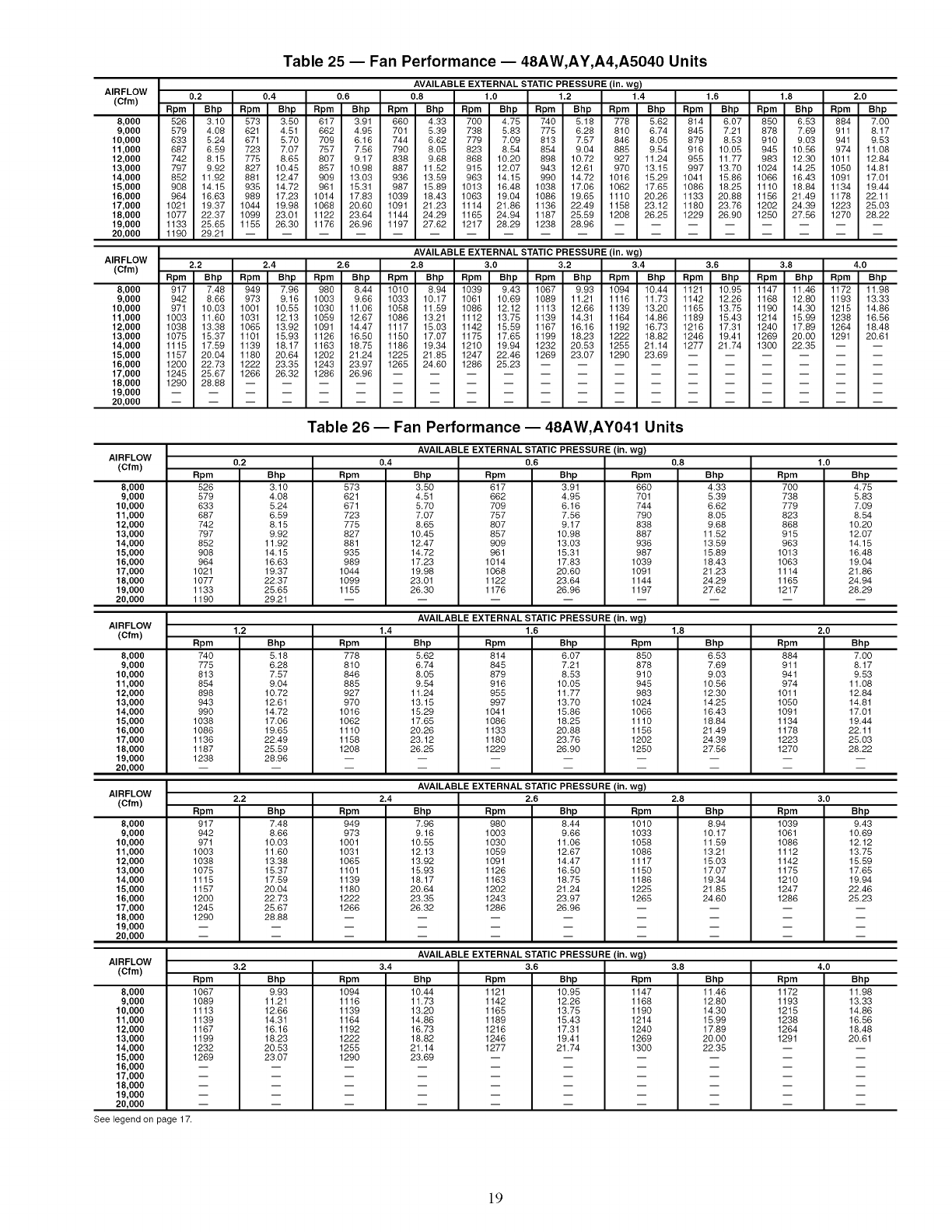
AIRFLOW
(Cfm)
8,000
9,000
10,000
11,000
12,000
13,000
14,000
15,000
16,000
17,000
18,000
19,000
20,000
AIRFLOW
(Of m)
8,000
9,000
10,000
11,000
12,000
13,000
14,000
15,000
16,000
17,000
18,000
19,000
20,000
Table 25 -- Fan Performance -- 48AW,AY,A4,A5040 Units
AVAILABLE EXTERNAL STATIC PRESSURE (in. wg)
0.2 0.4 0.6 0.8 1.0 1.2 1.4 1.6 1.8 2.0
Rpm Bhp Rpm Bhp Rpm Bhp Rpm Bhp Rpm Bhp Rpm Bhp Rpm Bhp Rpm Bhp Rpm Bhp Rpm Bhp
526 3.10 573 350 617 3.91 660 4.33 700 475 740 5.18 778 562 814 6.07 850 6.53 884 700
579 4.08 621 4.51 662 4.98 701 5.39 738 5.83 775 6.28 810 6.74 848 7.21 878 7.69 911 8.17
633 5.24 671 5.70 709 6.16 744 6.62 779 7.09 813 7.87 846 8.05 879 8.53 910 9.03 941 9.53
687 6.59 723 7.07 757 7.56 790 8.05 823 8.54 854 9.04 885 9.54 916 10.05 945 10.56 974 11.08
742 8.18 775 8.65 807 9.17 838 9.68 868 10.20 898 10.72 927 11.24 955 11.77 983 12.30 1011 12.84
797 9.92 827 10.45 857 10.98 887 11.52 915 12.07 943 12.61 970 13.15 997 13.70 1024 14.25 1050 14.81
852 11.92 881 12.47 909 13.03 936 13.59 963 14.15 990 14.72 1016 15.29 1041 15.86 1066 16.43 1091 17.01
908 14.15 935 14.72 961 15.31 987 18.89 1013 16.48 1038 17.06 1062 17.65 1086 18.25 1110 18.84 1134 19.44
964 16.63 989 17.23 1014 17.83 1039 18.43 1063 19.04 1086 19.65 1110 20.26 1133 20.88 1156 21.49 1178 22.11
1021 19.37 1044 19.98 1068 20.60 1091 21.23 1114 21.86 1136 22.49 1158 23.12 1180 23.76 1202 24.39 1223 25.03
1077 22.37 1099 23.01 1122 23.64 1144 24.29 1168 24.94 1187 25.59 1208 26.25 1229 26.90 1250 27.56 1270 28.22
1133 25.65 1155 26.30 1176 26.96 1197 27.62 1217 28.29 1238 28.96 ........
1190 29.21 ..................
AVAILABLE EXTERNAL STATIC PRESSURE (in. wg)
2.2 2.4 2,6 2.8 3.0 3.2 3.4 3.6 3.8 4.0
Rpm Bhp Rpm Bhp Rpm Bhp Rpm Bhp Rpm Bhp Rpm Bhp Rpm Bhp Rpm Bhp Rpm Bhp Rpm Bhp
917 7.48 949 796 980 8,44 1010 8.94 1039 943 1067 9.93 1094 10.44 1121 10.98 1147 11.46 1172 11.98
942 8.66 973 9.16 1003 9.66 1033 10.17 1061 10.69 1089 11.21 1116 11.73 1142 12.26 1168 12.80 1193 13.33
971 10.03 1001 10.55 1030 11.06 1058 11.59 1086 12.12 1113 12.66 1139 13.20 1165 13.75 1190 14.30 1215 14.86
1003 11.60 1031 12.13 1059 12.67 1086 13.21 1112 13.75 1139 14.31 1164 14.86 1189 15.43 1214 15.99 1238 16.56
1038 13.38 1065 13.92 1091 14.47 1117 15.03 1142 15.59 1167 16.16 1192 16.73 1216 17.31 1240 17.89 1264 18.48
1075 15.37 1101 15.93 1126 16.50 1150 17.07 1175 17.65 1199 18.23 1222 18.82 1246 19.41 1269 20.00 1291 20.61
1115 17.59 1139 18.17 1163 18.75 1186 19.34 1210 19.94 1232 20.53 1255 21.14 1277 21.74 1300 22.35 -- --
1157 20.04 1180 20.64 1202 21.24 1225 21.85 1247 22.46 1269 23.07 1290 23.69 ......
1200 22.73 1222 23.35 1243 23.97 1265 24.60 1286 25.23 ..........
1245 28.67 1266 26.32 1286 26.96 ..............
1290 28.88 ..................
AIRFLOW
(Cfm) Rpm
8,000 526
9,000 579
10,000 833
11,000 887
12,000 742
13,000 797
14,000 852
15,000 908
16,000 964
17,000 1021
18,000 1077
19,000 1133
20,000 1190
AIRFLOW
(Cfm) Rpm
8,000 740
9,000 775
10,000 813
11,000 854
12,000 898
13,000 943
14,000 990
15,000 1038
16,000 1086
17,000 1136
18,000 1187
19,000 1238
20,000
AIRFLOW
(Cfm) Rpm
8,000 917
9,000 942
10,000 971
11,000 1003
12,000 1038
13,000 1075
14,000 1115
15,000 1157
16,000 1200
17,000 1245
18,000 1290
19,000
20,000
AIRFLOW
(Cfm) Rpm
8,000 1067
9,000 1089
10,000 1113
11,000 1139
12,000 1167
13,000 1199
14,000 1232
15,000 1289
16,000
17,000
18,000
19,000
20,000
See legend on page 17.
Table 26 -- Fan Performance -- 48AW,AY041 Units
AVAILABLE EXTERNAL STATIC PRESSURE (in. wg)
0.2 0.4 0.6 0.8
Bhp
3.10
4.08
5.24
6.59
8.15
9.92
11.92
14.15
16.63
19.37
22.37
25.65
29.21
Rpm
573
621
671
723
775
827
881
935
989
1044
1099
1155
Bhp
3.50
4.51
5.70
7.07
8.65
10.45
12.47
14.72
17.23
19.98
23.01
26.30
Rpm
617
662
7O9
757
8O7
857
9O9
961
1014
1068
1122
1176
Bhp
3.91
4.95
6.16
7.56
9.17
10.98
13.03
15.31
17.83
20.60
23.64
26.96
Rpm
66O
701
744
79O
838
887
936
987
1039
1091
1144
1197
AVAILABLE EXTERNAL STATIC PRESSURE (in. wg)
1.2 1.4 1.6
Bhp
5.18
6.28
7.57
9.04
10.72
12.61
14.72
17.06
19.65
22.49
25.59
28.96
Rpm
778
810
846
885
927
97O
1016
1062
1110
1158
1208
Bhp
4.33
5.39
6.62
8.05
9.68
11.52
13.59
15.89
18.43
21.23
24.29
27.62
Bhp
5.62
6.74
8.05
9.54
11.24
13.15
15.29
17.65
20.26
23.12
26.25
Rpm
814
845
879
916
955
997
1041
1086
1133
1180
1229
Bhp
6.07
7.21
8.53
10.05
11.77
13.70
15.86
18.25
20.88
23.76
26.90
Rpm
85O
878
910
945
983
1024
1066
1110
1156
1202
1250
AVAILABLEEXTERNALSTATICPRESSURE(in. wg)
2.2 2,4 2,6
Bhp
7.48
8.66
10.03
11.60
13.38
15.37
17.59
20.04
22.73
25.67
28.88
1.8
Bhp
6.53
7.69
9.03
10.56
12.30
14.25
16.43
18.84
21.49
24.39
27.56
Rpm
949
973
1001
1031
1065
1101
1139
1180
1222
1266
Bhp
7.96
9.16
10.55
12.13
13.92
15.93
18.17
20.64
23.35
26.32
Rpm
98O
1003
1030
1059
1091
1126
1163
1202
1243
1286
Bhp
8.44
9.66
11.06
12.67
14.47
16.50
18.75
21.24
23.97
26.96
Rpm
1010
1033
1058
1086
1117
1150
1186
1225
1265
AVAILABLEEXTERNALSTATICPRESSURE(in. wg)
3.2 3.4 3.6
2.8
Bhp
894
10.17
11.59
13.21
18.03
17.07
19.34
21.85
24.60
Bhp
9.93
11.21
12.66
14.31
16.16
18.23
20.53
23.07
Rpm
1094
1116
1139
1164
1192
1222
1255
1290
Bhp
10.44
11.73
13.20
14.86
16.73
18.82
21.14
23.69
Rpm
1121
1142
1165
1189
1216
1246
1277
Bhp
10.95
12.26
13.75
15.43
17.31
19.41
21.74
Rpm
1147
1168
1190
1214
1240
1269
1300
3.8
Bhp
11.46
12.80
14.30
18.99
17.89
20.00
22.35
1.0
Rpm
7OO
738
779
823
868
915
963
1013
1063
1114
1165
1217
2.0
Rpm
884
911
941
974
1011
1050
1091
1134
1178
1223
1270
3.0
Rpm
1039
1061
1086
1112
1142
1175
1210
1247
1286
4.0
Rpm
1172
1193
1215
1238
1264
1291
Bhp
4.75
5.83
7.09
8.54
10.20
12.07
14.15
16.48
19.04
21.86
24.94
28.29
Bhp
7.00
8.17
9.53
11.08
12.84
14.81
17.01
19.44
22.11
25.03
28.22
Bhp
9.43
10.69
12.12
13.75
15.59
17.65
19.94
22.46
25.23
Bhp
11.98
13.33
14.86
16.56
18.48
20.61
[9
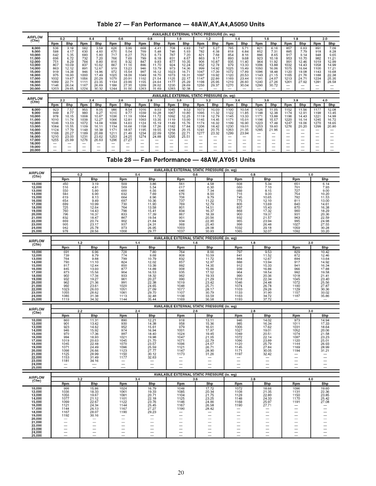
AIRFLOW
(Cfm)
8,000
9,000
10,000
11,000
12,000
13,000
14,000
15,000
16,000
17,000
18,000
19,000
20,000
AIRFLOW
(Cfm)
8,000
9,000
10,000
11,000
12,000
13,000
14,000
15,000
16,000
17,000
18,000
19,000
20,000
Table 27 -- Fan Performance -- 48AW,AY,A4,A5050 Units
AVAILABLE EXTERNAL STATIC PRESSURE (in. wg)
0.2 0.4 0.6 0.8 1.0 1.2 1.4 1.6 1.8 2.0
Bpm Bhp Bpm Bhp Bpm Bhp Bpm Bhp Bpm Bhp Bpm Bhp Bpm Bhp Bpm Bhp Bpm Bhp Bpm Bhp
536 3.18 582 3.58 626 3.99 668 4.41 708 4.83 747 5.27 785 5.71 821 6,16 857 6.63 891 7.09
588 4.17 630 4.60 670 5.04 709 5.48 746 5.93 782 6.38 818 6.84 852 7.31 885 7.79 918 8.28
642 5.35 680 5.80 717 6.27 753 6.73 787 7.20 821 7.68 854 8.16 886 8.65 917 9.14 948 9.65
696 6.72 732 7.20 766 7.69 799 8.18 831 8.67 863 9.17 893 9.68 923 10.18 953 10.70 982 11.21
751 8.29 784 8.80 816 9.32 847 9.83 877 10.35 906 10.87 935 11.40 964 11.92 991 12.46 1019 12.99
807 10.09 837 10.62 867 11.16 896 11.70 924 12.24 952 12.78 979 13.33 1006 13.88 1032 14.43 1058 14.99
863 12.12 891 12.67 919 13.23 946 13.79 973 14.36 999 14.92 1025 15.49 1050 16.06 1075 16.64 1100 17.21
919 14.38 946 14.96 972 15.54 997 16.12 1023 16.71 1047 17.30 1072 17.89 1096 18.48 1120 19.08 1143 19.68
975 16.90 1000 17.49 1025 18.00 1049 18.70 1073 19.31 1097 19.92 1120 20.53 1143 21.15 1165 21.76 1188 22.38
1032 19.67 1056 20.29 1079 20.91 1102 21.54 1125 22.17 1147 22.80 1169 23.44 1191 24.07 1213 24.71 1234 25.35
1089 22.71 1111 23.35 1134 23.99 1155 24.64 1177 25.29 1198 25.95 1219 26.60 1240 27.26 1261 27.92 1281 28.58
1146 26.04 1167 26.69 1188 27.35 1209 28.02 1230 28.69 1250 29.37 1270 30.04 1290 30.72 ....
1203 29.65 1224 30.32 1244 31.00 1263 31.69 1283 32.38 ..........
AVAILABLE EXTERNAL STATIC PRESSURE/in. w_!
2.2 2.4 2.6 2.8 3.0 3.2 3.4 3.6 3.8 4.0
Bpm Bhp Bpm Bhp Bpm Bhp Bpm Bhp Bpm Bhp Bpm Bhp Bpm Bhp Bpm Bhp Bpm Bhp Bpm Bhp
923 7.57 955 8.05 986 8.54 1016 9.03 1045 9.53 1073 10.03 1100 10.54 1126 11.05 1152 11.56 1177 12.08
949 8.77 980 9.27 1010 9.77 1039 10.28 1067 10.80 1095 11.32 1122 11.85 1148 12.38 1174 12.91 1199 13.45
078 10.15 1008 10.67 1036 11.19 1064 11.72 1092 12.25 1119 12.79 1145 13.33 1171 13.88 1196 14.43 1221 14.99
1010 11.74 1038 12.27 1066 12.81 1093 13.35 1119 13.90 1145 14.45 1171 15.01 1196 15.57 1220 16.14 1245 16.72
1046 13.53 1072 14.08 1098 14.63 1124 15.19 1149 15.76 1174 16.32 1199 16.90 1223 17.48 1247 18.06 1270 18.65
1084 15.55 1109 16.11 1134 16.68 1158 17.26 1182 17.84 1206 18.42 1230 19.01 1253 19.60 1276 20.20 1299 20.80
1124 17.79 1148 18.38 1171 18.97 1195 19.55 1218 20.15 1241 20.75 1263 21.35 1285 21.96 ....
1166 20.27 1189 20.88 1211 21.49 1234 22.09 1256 22.71 1277 23.32 1299 23.94 ......
1210 23.00 1231 23.62 1253 24.25 1274 24.88 1295 25.51 ..........
1255 25.99 1276 26.63 1296 27.27 ..............
Table 28 -- Fan Performance -- 48AW,AY051 Units
AVAILABLE EXTERNAL STATIC PRESSURE (in. wg)
AIRFLOW 0.2 0.4 0.6
(Cfm)
10,000
12,000
13,000
14,000
15,000
16,000
17,000
18,000
19,000
20,000
21,000
22,000
23,000
24,000
25,000
Rpm
45O
516
550
584
619
654
689
725
76O
796
832
869
905
942
976
Bhp
3.19
4.81
5.80
6.90
8.13
9.49
10.99
12.64
14.43
16.37
18.47
20.74
23.17
25.76
28.56
Rpm
5O9
569
600
632
664
697
730
764
798
833
867
902
937
973
1008
Bhp
3.86
5.54
6.56
7.69
8.96
10,36
11,90
18.56
15,41
17.39
19,54
21,84
24.31
26.95
29,77
Rpm
561
617
646
676
706
737
769
801
834
867
901
934
968
1003
1037
Bhp Rpm
4.58 608
6.30 660
7.34 688
8.50 716
9.79 745
11.22 775
12.79 806
14.51 837
16.37 868
18.39 900
20.56 932
22.90 965
25.40 998
28.08 1032
30.93 1065
AVAILABLE EXTERNAL STATIC PRESSURE (in. wg)
AIRFLOW
(Cfm) 1.2 1.4 1.6
Bpm
728
774
799
824
850
877
904
933
961
991
1020
1051
1081
1113
1144
10,000
12,000
13,000
14,000
15,000
16,000
17,000
18,000
19,000
20,000
21,000
22,000
23,000
24,000
25,000
Bhp
6.96
8.79
9.88
11.10
12.44
13.93
15.56
17.34
19.27
21.36
23.61
26.03
28.62
31.38
34.32
Bpm
691
789
764
790
817
845
873
902
982
962
992
1023
1055
1086
1119
Bhp
7.80
9.68
10.79
12.02
13.38
14.88
16.53
18.32
20.27
22.38
24.65
27.09
29.70
32.48
35.44
Bpm
764
808
832
857
882
908
935
962
990
1019
1048
1077
1107
1138
1169
Bhp
8.66
10.59
11.72
12.97
14.35
15.86
17.52
19.33
21.29
23.42
25.71
28.17
30.79
33.59
36.58
AVAILABLE EXTERNAL STATIC PRESSURE (in. wg)
AIRFLOW
(Cfm) 2.2 2.4 2.6
Bpm
86o
9Ol
923
946
970
994
lO19
1045
1071
1098
1125
1153
1181
3.2
10,000
12,000
13,000
14,000
15,000
16,000
17,000
18,000
19,000
20,000
21,000
22,000
23,000
24,000
25,000
AIRFLOW
(Cfm)
10,000
12,000
13,000
14,000
15,000
16,000
17,000
18,000
19,000
20,000
21,000
22,000
23,000
24,000
25,000
Bpm
998
1036
1056
1077
1099
1121
1144
1167
1192
Bpm
797
841
864
888
912
938
964
990
1018
1046
1074
1103
1133
1163
1193
0.8
Bhp
5,34
7.10
8.15
9,33
10.65
12,10
13.69
15,43
17.32
19,37
21,57
23.94
26.48
29.18
32,07
1.8
Bhp
9.53
11.52
12.67
13.94
15.33
16.86
18.54
20.36
22.34
24.48
26.78
29.26
31.90
34.72
37.72
1.0
Rpm
651
701
727
754
782
811
84O
87O
900
931
963
995
1027
1059
1092
2.0
Bpm
829
872
894
917
941
966
992
1016
1045
1072
1100
1129
1157
1187
Bhp
6,14
7.93
9,00
10.20
11.53
13.00
14.61
16.38
18.29
20.36
22.59
24.98
27.55
30.28
33.20
Bhp
10.42
12.46
13.64
14.92
16.34
17.88
19.58
21.41
23.40
25.56
27.87
30.36
33.02
35.86
Bhp
11.31
13.42
14.62
15.92
17.36
18.93
20.63
22.48
24.49
26.66
28.99
31.49
34.16
Bpm
89o
930
952
974
997
lO21
1045
1070
1096
1123
1150
1177
Bhp
12.21
14.38
15.61
16.94
18.40
19.98
21.70
23.57
25.59
27.77
30.12
32.63
Bpm
918
958
979
1001
1024
1047
1071
1096
1121
1147
1173
Bhp
13.11
15.36
16.61
17.97
19.45
21.65
22,79
24.67
26.71
28.90
31.26
Bpm
946
985
1006
1027
1049
1072
1096
1120
1145
1171
1197
2.8
Bhp
14.02
16.34
17.62
19.01
20.51
22.14
23.89
25.79
27.84
30.05
32.42
3.0
Bpm
973
lOll
lO31
lO52
lO74
lO97
112o
1144
1169
1194
Bhp
14.94
17.33
18.64
20.06
21.58
23.23
25.01
26.93
28.99
31.21
Bhp
15.86
18.33
19.67
21.12
22.67
24.34
26.13
28.07
30.16
Bpm
1024
1061
1081
1101
1122
1144
1167
1190
3.4
AVAILABLE EXTERNAL STATIC PRESSURE (in. w_)
3.6
Bhp
16.79
19.33
20.71
22.18
23.76
25.45
27.27
29.23
Bpm
1048
1085
1104
1125
1146
1167
1190
Bhp
17.72
20.34
21.75
23.25
24.86
26.58
28.42
Bpm
1072
1108
1128
1148
1168
1190
3.8
Bhp
18.66
21.35
22.80
24.33
25.97
27.71
4.0
Bpm
lO96
1131
115o
117o
1191
Bhp
19.60
22.36
23.85
25.42
27.08
20
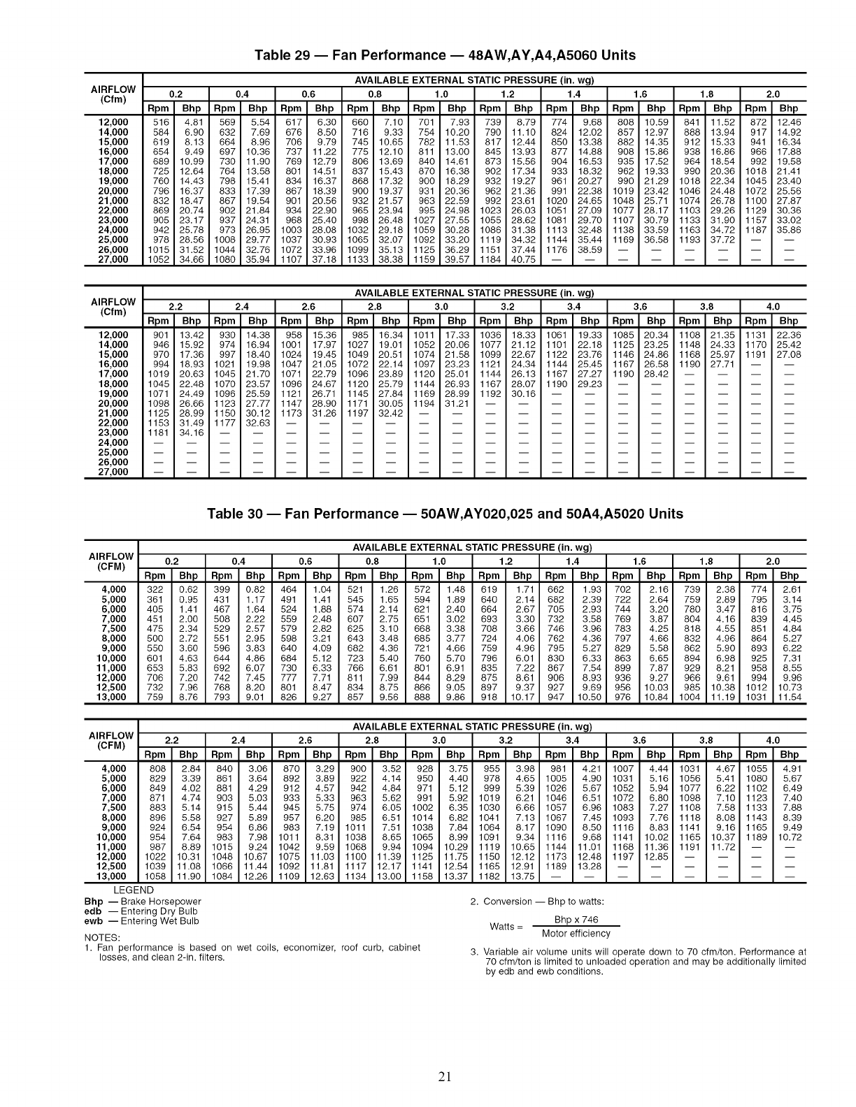
AIRFLOW
(Cfm)
12,000
14,000
15,000
16,000
17,000
18,000
19,000
20,000
21,000
22,000
23,000
24,000
25,000
26,000
27,000
Table 29 -- Fan Performance -- 48AW,AY,A4,A5060 Units
AVAILABLE EXTERNAL STATIC PRESSURE (in. wg)
0.2 0.4 0.6 0.8 1.0 1.2 1.4 1.6 1.8 2.0
Rpm Bhp Rpm Bhp Rpm Bhp Rpm Bhp Rpm Bhp Rpm Bhp Rpm Bhp Rpm Bhp Rpm Bhp Rpm Bhp
516 4.81 569 5.54 617 6.30 660 7.10 701 7.93 739 8.79 774 9.68 808 10.59 841 11.52 872 12.46
584 6.90 632 7.69 676 8.50 716 9.33 754 10.20 790 11.10 824 12.02 857 12.97 888 13.94 917 14.92
619 8.13 664 8.96 706 9.79 745 10.65 782 11.53 817 12.44 850 13.38 882 14.35 912 15.33 941 16.34
654 9.49 697 10.36 737 11.22 775 12.10 811 13.00 845 13.93 877 14.88 908 15.86 938 16.86 966 17.88
689 10.99 730 11.90 769 12.79 806 13.69 840 14.61 873 15.56 904 16.53 935 17.52 964 18.54 992 19.58
725 12.64 764 13.58 801 14.51 837 15.43 870 16.38 902 17.34 933 18.32 962 19.33 990 20.36 1018 21.41
760 14.43 798 15.41 834 16.37 868 17.32 900 18.29 932 19.27 961 20.27 990 21.29 1018 22.34 1045 23.40
796 16.37 833 17.39 867 18.39 900 19.37 931 20.36 962 21.36 991 22.38 1019 23.42 1046 24.48 1072 25.56
832 18.47 867 19.54 901 20.56 932 21.57 963 22.59 992 23.61 1020 24.65 1048 25.71 1074 26.78 1100 27.87
869 20.74 902 21.84 934 22.90 965 23.94 995 24.98 1023 26.03 1051 27.09 1077 28.17 1103 29.26 1129 30.36
905 23.17 937 24.31 968 25.40 998 26.48 1027 27.55 1055 28.62 1081 29.70 1107 30.79 1133 31.90 1157 33.02
942 25.78 973 26.95 1003 28.08 1032 29.18 1059 30.28 1086 31.38 1113 32.48 1138 33.59 1163 34.72 1187 35.86
978 28.56 1008 29.77 1037 30.93 1065 32.07 1092 33.20 1119 34.32 1144 35.44 1169 36.58 1193 37.72 -- --
1015 31.52 1044 32.76 1072 33.96 1099 35.13 1125 36.29 1151 37.44 1176 38.59 ......
1052 34.66 1080 35.94 1107 37.18 1133 38.38 1159 39.57 1184 40.75 ........
AIRFLOW
(Cfm)
12,000
14,000
15,000
16,000
17,000
18,000
19,000
20,000
21,000
22,000
23,000
24,000
25,000
26,000
27,000
AVAILABLE EXTERNAL STATIC PRESSURE (in. wg)
2.2 2.4 2.6 2.8 3.0 3.2 3.4 3.6 3.8 4.0
Rpm Bhp Rpm Bhp Rpm Bhp Rpm Bhp Rpm Bhp Rpm Bhp Rpm Bhp Rpm Bhp Rpm Bhp Rpm Bhp
901 13.42 930 14.38 958 15.36 985 16.34 1011 17.33 1036 18.33 1061 19.33 1085 20.34 1108 21.35 1131 22.36
946 15.92 974 16.94 1001 17.97 1027 19.01 1052 20.06 1077 21.12 1101 22.18 1125 23.25 1148 24.33 1170 25.42
970 17.36 997 18.40 1024 19.45 1049 20.51 1074 21.58 1099 22.67 1122 23.76 1146 24.86 1168 25.97 1191 27.08
994 18.93 1021 19.98 1047 21.05 1072 22.14 1097 23.23 1121 24.34 1144 25.45 1167 26.58 1190 27.71 -- --
1019 20.63 1045 21.70 1071 22.79 1096 23.89 1120 25.01 1144 26.13 1167 27.27 1190 28.42 ....
1045 22.48 1070 23.57 1096 24.67 1120 25.79 1144 26.93 1167 28.07 1190 29.23 ......
1071 24.49 1096 25.59 1121 26.71 1145 27.84 1169 28.99 1192 30.16 ........
1098 26.66 1123 27.77 1147 28.90 1171 30.05 1194 31.21 ..........
1125 28.99 1150 30.12 1173 31.26 1197 32.42 ............
1153 31.49 1177 32.63 ................
1181 34.16 ..................
Table 30 -- Fan Performance -- 50AW,AY020,025 and 50A4,A5020 Units
AIRFLOW
(CFM)
4,000
5,000
6,000
7,000
7,500
8,000
9,000
10,000
11,000
12,000
12,500
13,000
AVAILABLE EXTERNAL STATIC PRESSURE (in. wg)
0.2 0.4 0.6 0.8 1.0 1.2 1.4 1.6 1.8 2.0
Rpm Bhp Rpm Bhp Rpm Bhp Rpm Bhp Rpm Bhp Rpm Bhp Rpm Bhp Rpm Bhp Rpm Bhp Rpm Bhp
322 0.62 399 0.82 464 1.04 521 1.26 572 1.48 619 1.71 662 1.93 702 2.16 739 2.38 774 2.61
361 0.95 431 1.17 491 1.41 545 1.65 594 1.89 640 2.14 682 2.39 722 2.64 759 2.89 795 3.14
405 1.41 467 1.64 524 1.88 574 2.14 621 2.40 664 2.67 705 2.93 744 3.20 780 3.47 816 3.75
451 2.00 508 2.22 559 2.48 607 2.75 651 3.02 693 3.30 732 3.58 769 3.87 804 4.16 839 4.45
475 2.34 529 2.57 579 2.82 625 3.10 668 3.38 708 3.66 746 3.96 783 4.25 818 4.55 851 4.84
500 2.72 551 2.95 598 3.21 643 3.48 685 3.77 724 4.06 762 4.36 797 4.66 832 4.96 864 5.27
550 3.60 596 3.83 640 4.09 682 4.36 721 4.66 759 4.96 795 5.27 829 5.58 862 5.90 893 6.22
601 4.63 644 4.86 684 5.12 723 5.40 760 5.70 796 6.01 830 6.33 863 6.65 894 6.98 925 7.31
653 5.83 692 6.07 730 6.33 766 6.61 801 6.91 835 7.22 867 7.54 899 7.87 929 8.21 958 8.55
706 7.20 742 7.45 777 7.71 811 7.99 844 8.29 875 8.61 906 8.93 936 9.27 966 9.61 994 9.96
732 7.96 768 8.20 801 8.47 834 8.75 866 9.05 897 9.37 927 9.69 956 10.03 985 10.38 1012 10.73
759 8.76 793 9.01 826 9.27 857 9.56 888 9.86 918 10.17 947 10.50 976 10.84 1004 11.19 1031 11.54
AIRFLOW
(CFM)
4,000
5,000
6,000
7,000
7,500
8,000
9,000
10,000
11,000
12,000
12,500
13,000
LEGEND
Bhp -- Brake Horsepower
edb -- Entering Dry Bulb
ewb -- Entering Wet Bulb
AVAILABLE EXTERNAL STATIC PRESSURE (in. wg)
2.2 2.4 2.6 2.8 3.0 3.2 3.4 3.6 3.8 4.0
Rpm Bhp Rpm Bhp Rpm Bhp Rpm Bhp Rpm Bhp Rpm Bhp Rpm Bhp Rpm Bhp Rpm Bhp Rpm Bhp
808 2.84 840 3.06 870 3.29 900 3.52 928 3.75 955 3.98 981 4.21 1007 4.44 1031 4.67 1055 4.91
829 3.39 861 3.64 892 3.89 922 4.14 950 4.40 978 4.65 1005 4.90 1031 5.16 1056 5.41 1080 5.67
849 4.02 881 4.29 912 4.57 942 4.84 971 5.12 999 5.39 1026 5.67 1052 5.94 1077 6.22 1102 6.49
871 4.74 903 5.03 933 5.33 963 5.62 991 5.92 1019 6.21 1046 6.51 1072 6.80 1098 7.10 1123 7.40
883 5.14 915 5.44 945 5.75 974 6.05 1002 6.35 1030 6.66 1057 6.96 1083 7.27 1108 7.58 1133 7.88
896 5.58 927 5.89 957 6.20 985 6.51 1014 6.82 1041 7.13 1067 7.45 1093 7.76 1118 8.08 1143 8.39
924 6.54 954 6.86 983 7.19 1011 7.51 1038 7.84 1064 8.17 1090 8.50 1116 8.83 1141 9.16 1165 9.49
954 7.64 983 7.98 1011 8.31 1038 8.65 1065 8.99 1091 9.34 1116 9.68 1141 10.02 1165 10.37 1189 10.72
987 8.89 1015 9.24 1042 9.59 1068 9.94 1094 10.29 1119 10.65 1144 11.01 1168 11.36 1191 11.72 -- --
1022 10.31 1048 10.67 1075 11.03 1100 11.39 1125 11.75 1150 12.12 1173 12.48 1197 12.85 ....
1039 11.08 1066 11.44 1092 11.81 1117 12.17 1141 12.54 1165 12.91 1189 13.28 ......
1058 11.90 1084 12.26 1109 12.63 1134 13.00 1158 13.37 1182 13.75 ........
NOTES:
1. Fan performance is based on wet coils, economizer, roof curb, cabinet
losses, and clean 2-in. filters.
2. Conversion -- Bhp to watts:
Bhp x 746
Watts = Motor efficiency
3. Variable air volume units will operate down to 70 cfm/ton. Performance at
70 cfm/ton is limited to unloaded operation and may be additionally limited
by edb and ewb conditions.
2!
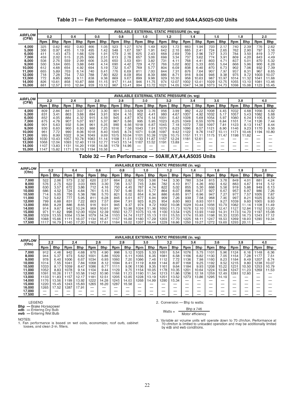
Table 31 -- Fan Performance -- 50AW,AY027,030 and 50A4,A5025-030 Units
AVAILABLE EXTERNAL STATIC PRESSURE (in. wg)
AIRFLOW 0.8 1.0 1.2 1.4 1.6
(CFM)
4,000
5,000
6,000
7,000
8,000
9,000
10,000
11,000
12,000
13,000
14,000
15,000
AIRFLOW
(CFM)
4,000
5,000
6,000
7,000
8,000
9,000
10,000
11,000
12,000
13,000
14,000
15,000
AIRFLOW
(Cfm)
7,000
8,000
9,000
10,000
10,500
11,000
12,000
13,000
14,000
15,000
16,000
17,000
17,500
0.2
Rpm Bhp
325 0.62
366 0.97
411 1.43
459 2.02
508 2.76
560 3.64
612 4.68
665 5.89
718 7.28
772 8.85
826 10.61
881 12.57
0.4 0.6 1.8 2.0
Rpm Bhp Rpm Bhp Rpm Bhp Rpm Bhp Rpm Bhp Rpm Bhp Rpm Bhp Rpm Bhp Rpm Bhp
402 0.83 466 1.05 523 1.27 574 1.49 620 1.72 663 1.94 703 2.17 740 2.39 776 2.62
435 1.19 495 1.42 548 1.67 597 1.91 642 2.16 685 2.41 724 2.65 762 2.90 797 3.16
473 1.66 529 1.91 579 2.16 625 2.43 668 2.69 709 2.96 747 3.23 784 3.50 819 3.77
515 2.25 566 2.51 613 2.78 657 3.06 698 3.34 737 3.62 774 3.91 809 4.20 843 4.49
559 2.99 606 3.25 650 3.53 691 3.82 731 4.11 768 4.41 803 4.71 837 5.01 870 5.32
605 3.88 649 4.14 690 4.42 729 4.72 766 5.02 802 5.33 835 5.64 868 5.96 900 6.28
654 4.92 694 5.19 732 5.47 769 5.77 804 6.09 838 6.40 870 6.73 902 7.06 932 7.39
703 6.14 740 6.41 776 6.69 811 7.00 844 7.31 876 7.64 907 7.97 937 8.31 967 8.65
754 7.53 788 7.80 822 8.09 854 8.39 886 8.71 916 9.04 946 9.38 975 9.72 1003 10.07
806 9.11 838 9.38 869 9.67 899 9.98 929 10.30 958 10.63 987 10.97 1014 11.32 1041 11.68
858 10.87 888 11.15 917 11.44 946 11.75 974 12.07 1002 12.41 1029 12.75 1055 13.10 1081 13.46
910 12.84 939 13.12 967 13.41 994 13.72 1021 14.05 1047 14.38 1073 14.73 1098 15.08 1123 15.45
2.2
Rpm Bhp
809 2.84
831 3.41
852 4.05
875 4.78
901 5.63
930 6.60
961 7.72
995 8.99
1030 10.43
1068 12.04
1107 13.83
1147 15.82
AVAILABLE EXTERNAL STATIC PRESSURE(in. wg)
2.4 2.6 2.8 3.0 3.2 3.4 3.6 3.8 4.0
Rpm Bhp Rpm Bhp Rpm Bhp Rpm Bhp Rpm Bhp Rpm Bhp Rpm Bhp Rpm Bhp Rpm Bhp
841 3.07 872 3.30 901 3.53 929 3.76 956 3.99 982 4.22 1008 4.45 1032 4.68 1056 4.92
863 3.66 894 3.91 924 4.16 952 4.41 980 4.67 1007 4.92 1032 5.17 1057 5.43 1082 5.68
884 4.32 915 4.59 945 4.87 974 5.14 1001 5.42 1028 5.69 1054 5.97 1080 6.24 1105 6.52
907 5.07 937 5.37 967 5.66 995 5.95 1023 6.25 1049 6.55 1076 6.84 1101 7.14 1126 7.44
932 5.94 961 6.25 990 6.56 1018 6.87 1045 7.18 1072 7.50 1097 7.81 1123 8.13 1147 8.44
960 6.93 988 7.25 1016 7.58 1043 7.91 1070 8.23 1096 8.57 1121 8.90 1146 9.23 1170 9.56
990 8.06 1018 8.40 1045 8.74 1071 9.08 1097 9.42 1122 9.76 1147 10.11 1171 10.46 1194 10.80
1022 9.34 1049 9.69 1075 10.04 1101 10.39 1126 10.75 1151 11.11 1175 11.47 1198 11.82 -- --
1057 10.78 1083 11.14 1108 11.51 1133 11.87 1157 12.24 1181 12.61 ......
1093 12.40 1119 12.77 1143 13.14 1167 13.52 1191 13.89 ........
1131 14.20 1156 14.58 1179 14.96 ............
1171 16.19 1194 16.58 ..............
Table 32 -- Fan Performance -- 50AW,AY,A4,A5035 Units
0.2 0.4
Rpm Bhp Rpm Bhp
522 2.06 573 2.32
576 2.75 622 3.03
630 3.57 672 3.86
686 4.52 724 4.84
714 5.05 750 5.38
742 5.62 777 5.95
799 6.88 831 7.22
856 8.29 886 8.65
914 9.87 942 10.24
971 11.62 998 12.00
1029 13.55 1054 13.94
1088 15.66 1111 16.07
1117 16.79 1140 17.20
AVAILABLE EXTERNAL STATIC PRESSURE(in. wg)
0.6 0.8 1.0 1.2 1.4 1.6 1.8 2.0
Rpm Bhp Rpm Bhp Rpm Bhp Rpm Bhp Rpm Bhp Rpm Bhp Rpm Bhp Rpm Bhp
620 2.57 664 2.82 705 3.06 744 3.30 780 3.54 815 3.78 849 4.01 881 4.24
665 3.30 706 3.57 745 3.84 782 4.10 817 4.36 850 4.62 883 4.87 914 5.12
712 4.16 750 4.45 787 4.74 822 5.02 855 5.30 888 5.58 919 5.86 949 6.13
761 5.15 797 5.46 831 5.77 864 6.07 896 6.37 927 6.67 957 6.97 986 7.26
786 5.70 821 6.02 854 6.34 886 6.65 917 6.96 947 7.27 977 7.57 1005 7.87
811 6.28 845 6.61 877 6.94 909 7.26 939 7.58 968 7.90 997 8.21 1025 8.52
863 7.57 894 7.91 925 8.25 954 8.60 983 8.93 1011 9.27 1039 9.60 1065 9.93
916 9.01 945 9.37 974 9.72 1002 10.08 1029 10.44 1056 10.79 1082 11.14 1108 11.49
969 10.61 997 10.98 1024 11.36 1050 11.73 1076 12.10 1102 12.47 1127 12.84 1152 13.20
1024 12.39 1050 12.77 1075 13.16 1100 13.54 1125 13.93 1149 14.31 1173 14.70 1197 15.08
1079 14.34 1103 14.74 1127 15.13 1151 15.53 1174 15.93 1198 16.33 1220 16.73 1243 17.12
1134 16.47 1157 16.88 1180 17.29 1203 17.70 1225 18.11 1247 18.53 1269 18.93 1290 19.34
1162 17.61 1184 18.02 1207 18.44 1229 18.86 1250 19.27 1272 19.69 1293 20.11 -- --
AIRFLOW
(Cfm)
7,000
8,000
9,000
10,000
10,500
11,000
12,000
13,000
14,000
15,000
16,000
17,000
17,500
2.2 2.4
Rpm Bhp Rpm Bhp
912 4.46 942 4.68
944 5.37 973 5.62
978 6.40 1006 6.67
1014 7.55 1041 7.84
1033 8.17 1059 8.47
1052 8.83 1078 9.14
1091 10.26 1117 10.58
1133 11.83 1157 12.17
1176 13.56 1199 13.92
1220 15.45 1243 15.83
1265 17.52 1287 17.91
AVAILABLE EXTERNAL STATIC PRESSURE (in. wg)
2.6 2.8 3.0 3.2 3.4 3.6 3.8 4.0
Rpm Bhp Rpm Bhp Rpm Bhp Rpm Bhp Rpm Bhp Rpm Bhp Rpm Bhp Rpm Bhp
970 4.90 998 5.12 1025 5.33 1051 5.54 1076 5.75 1101 5.96 1124 6.16 1148 6.36
1001 5.86 1029 6.11 1055 6.35 1081 6.58 1106 6.82 1130 7.05 1154 7.28 1177 7.51
1034 6.93 1060 7.20 1086 7.46 1112 7.72 1136 7.98 1160 8.23 1184 8.49 1207 8.74
1068 8.12 1094 8.41 1119 8.69 1144 8.97 1168 9.25 1192 9.52 1215 9.80 1238 10.07
1086 8.77 1111 9.06 1136 9.35 1161 9.64 1184 9.93 1208 10.22 1231 10.50 1253 10.79
1104 9.44 1129 9.75 1154 10.05 1178 10.35 1201 10.64 1224 10.94 1247 11.23 1269 11.53
1142 10.90 1166 11.23 1190 11.54 1213 11.86 1236 12.18 1259 12.49 1281 12.80 -- --
1181 12.51 1205 12.85 1228 13.19 1251 13.52 1273 13.86 1295 14.19 ....
1222 14.28 1245 14.63 1268 14.99 1290 15.34 ........
1265 16.20 1287 16.58 ............
LEGEND
Bhp -- Brake Horsepower
edb -- Entering Dry Bulb
ewb -- Entering Wet Bulb
NOTES:
1. Fan performance is based on wet coils, economizer, roof curb, cabinet
losses, and clean 2-in. filters.
2. Conversion -- Bhp to watts:
Bhp x 746
Watts = Motor efficiency
3. Variable air volume units will operate down to 70 cfm/ton. Performance at
70 cfm/ton is limited to unloaded operation and may be additionally limited
by edb and ewb conditions.
22
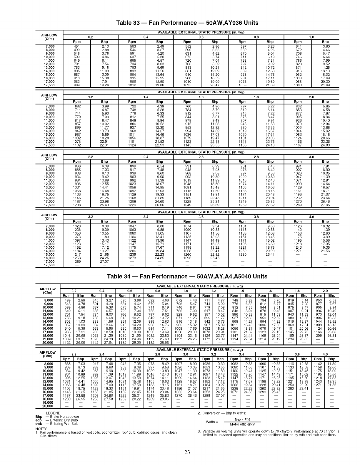
Table 33 -- Fan Performance -- 50AW,AY036 Units
AVAILABLE EXTERNAL STATIC PRESSURE (in. wg)
AIRFLOW
(Cfm) 0.4 0.6
0.2
Rpm
451
499
548
599
649
701
753
805
857
910
963
989
7,000
8,000
9,000
10,000
11,000
12,000
13,000
14,000
15,000
16,000
17,000
17,500
Bhp
2.13
2.88
3.78
4.86
6.11
7.54
9.18
11.03
13.09
15.38
17.91
19.26
Rpm
5O3
546
591
637
685
734
783
833
884
935
986
1012
Bhp
2.49
3.27
4.20
5.30
6.57
8.03
9.69
11.56
13.64
15.95
18.50
19.86
Rpm
552
59O
631
675
720
766
813
861
910
960
1010
1035
Bhp
2.86
3.66
4.62
5.74
7.04
8.52
10.21
12.09
14.20
16.53
19.09
20.47
Rpm
597
632
670
711
753
797
842
889
936
984
1033
1058
AVAILABLE EXTERNAL STATIC PRESSURE (in. wg)
AIRFLOW
(Cfm) 1.4 1.6
1.2
Rpm
682
711
744
779
817
857
899
942
987
1032
1078
1102
7,000
8,000
9,000
10,000
11,000
12,000
13,000
14,000
15,000
16,000
17,000
17,500
Bhp
3.99
4.87
5.90
7.09
8.47
10.02
11.77
13.73
15.89
18.28
20.91
22.31
Rpm
722
748
778
812
848
886
927
968
1011
1056
1101
1124
Bhp
4.39
5.28
6.33
7.55
8.94
10.52
12.30
14.27
16.46
18.87
21.52
22.93
Rpm
76O
784
812
844
878
915
953
994
1036
1079
1123
1145
Bhp
4.80
5.70
6.77
8.01
9.43
11.03
12.82
14.82
17.03
19.47
22.13
23.55
Rpm
797
819
845
875
9O7
943
98O
1019
1060
1101
1145
1166
0.8
Bhp
323
406
504
619
751
902
10.72
12.63
14.76
17.11
1969
21.08
AVAILABLE EXTERNAL STATIC PRESSURE (in. wg)
AIRFLOW
(Cfm) 2,4 2,6
2.2
Rpm
866
885
908
934
964
996
1031
1068
1106
1146
1187
1208
7,000
8,000
9,000
10,000
11,000
12,000
13,000
14,000
15,000
16,000
17,000
17,500
Bhp
6.09
7.03
8.13
9.42
10.89
12.55
14.41
16.48
18.75
21.25
23.98
25.43
Rpm
899
917
939
963
992
1023
1056
1092
1129
1168
1208
1229
Bhp
6.54
7.48
8.60
9.90
11.39
13.07
14.95
17.03
19.33
21.85
24.60
26.06
1.8
Bhp
522
614
722
847
991
11.53
13.35
15.37
17.61
20.06
22.75
24.18
Rpm
931
948
968
992
1019
1048
1081
1115
1151
1189
1229
1249
Bhp
6.99
7.95
9.08
10.39
11.89
13.59
15.48
17.59
19.91
22.45
25.21
26.69
Rpm
961
978
997
1020
1045
1074
1105
1138
1174
1211
1249
1269
AVAILABLE EXTERNAL STATIC PRESSURE (in. wg)
AIRFLOW
(Cfm) 3.4 3.6
3.2
Rpm
1020
1036
1053
1073
1097
1123
1152
1184
1217
1253
1289
7,000
8,000
9,000
10,000
11,000
12,000
13,000
14,000
15,000
16,000
17,000
17,500
2.8
Bhp
745
842
956
10.89
12.40
14.11
16.03
18.15
20.48
23.04
25.83
27.32
Bhp
8.39
9.39
10.55
11.89
13.43
15.17
17.12
19.27
21.65
24.25
27.07
Rpm
1047
1063
1080
1100
1122
1147
1175
1206
1239
1273
Bhp
8.86
9.88
11.05
12.41
13.96
15.71
17.67
19.84
22.23
24.85
Rpm
1074
1090
1107
1125
1147
1171
1198
1228
1260
1293
Bhp
9.34
10.38
11.56
12.93
14.49
16.25
18.22
20.41
22.82
25.45
Rpm
1101
1116
1133
1151
1171
1195
1221
1250
1280
3.8
Bhp
983
10.88
12,08
13.45
15.02
16.80
18.78
20.99
23.41
1.0
Rpm
641
672
7O8
746
786
828
871
916
962
1008
1056
1080
2,0
Rpm
832
853
877
9O5
936
97O
1006
1044
1083
1124
1166
1187
3.0
Rpm
991
1007
1026
1047
1071
1099
1129
1161
1196
1232
1270
1289
4,0
Rpm
1126
1142
1158
1175
1195
1218
1243
1271
Bhp
3.60
4.46
5.47
6.64
7.99
9.52
11.25
13.18
15.32
17.69
20.30
21.69
Bhp
5.65
6.58
7.67
8.94
10.40
12.04
13.88
15.92
18.18
20.66
23.36
24.80
Bhp
7.91
8.90
10.05
11.39
12.91
14.64
16.57
18.71
21.07
23.64
26.46
27.95
Bhp
10.32
11.39
12.60
13.99
15.56
17.35
19.35
21.56
Table 34 -- Fan Performance -- 50AW,AY,A4,A5040 Units
AIRFLOW
(Cfm)
8,000
9,000
10,000
11,000
12,000
13,000
14,000
15,000
16,000
17,000
18,000
19,000
20,000
AVAILABLE EXTERNAL STATIC PRESSURE (in. wg)
0.2 0.4 0.6 0.8 1.0 1.2 1.4 1.6 1.8 2.0
Rpm Bhp Rpm Bhp Rpm Bhp Rpm Bhp Rpm Bhp Rpm Bhp Rpm Bhp Rpm Bhp Rpm Bhp Rpm Bhp
499 2,88 546 327 590 3.66 632 4.06 672 446 711 4.87 748 528 784 5.70 819 6.14 853 658
548 3.78 591 4.20 631 4.62 670 5.04 708 5.47 744 5.90 778 6.33 812 6.77 845 7.22 877 7.67
599 4.86 637 5.30 675 5.74 711 6.19 746 6.64 779 7.09 812 7.55 844 8,01 875 8.47 905 8.94
649 6.11 685 6.57 720 7.04 753 7.51 786 7.99 817 8.47 848 8.94 878 9.43 907 9.91 936 10.40
701 7.54 734 8.03 766 8.52 797 9.02 828 9.52 857 10.02 886 10.52 915 11.03 943 11.53 970 12.04
753 9.18 783 9.69 813 10.21 842 10.72 871 11.25 899 11.77 927 12.30 953 12.82 980 13.35 1006 13.88
805 11.03 833 11.56 861 12.09 889 12.63 916 13.18 942 13.73 968 14.27 994 14.82 1019 15.37 1044 15.92
857 13.09 884 13.64 910 14.20 936 14.76 962 15.32 987 15.89 1011 16.46 1036 17.03 1060 17.61 1083 18.18
910 15.38 935 15.95 960 16.53 984 17.11 1008 17.69 1032 18.28 1056 18.87 1079 19.47 1101 20.06 1124 20.66
963 17.91 986 18.50 1010 19.09 1033 19.69 1056 20.30 1078 20.91 1101 21.52 1123 22.13 1145 22.75 1166 23.36
1016 20.68 1038 21.29 1060 21.90 1082 22.52 1104 23.15 1126 23.77 1147 24.41 1168 25.04 1189 25.67 1209 26.31
1069 23.71 1090 24.33 1111 24.96 1132 25.60 1153 26.25 1173 26.89 1194 27.54 1214 28.19 1234 28.85 -- --
1122 26.99 1142 27.64 1162 28.29 1182 28.95 ............
AIRFLOW
(Cfm)
8,000
9,000
10,000
11,000
12,000
13,000
14,000
15,000
16,000
17,000
18,000
19,000
20,000
AVAILABLE EXTERNAL STATIC PRESSURE (in. wg)
2.2 2.4 2.6 2.8 3.0 3.2 3.4 3.6 3.8 4.0
Rpm Bhp Rpm Bhp Rpm Bhp Rpm Bhp Rpm Bhp Rpm Bhp Rpm Bhp Rpm Bhp Rpm Bhp Rpm Bhp
885 7.03 917 748 948 7.95 978 8.42 1007 890 1036 9.39 1063 988 1090 10.38 1116 10.88 1142 11 39
908 8.13 939 8.60 968 9.08 997 9.56 1026 10.05 1053 10.55 1080 11.05 1107 11.56 1133 12,08 1158 12.60
934 9.42 963 9.90 992 10.39 1020 10.89 1047 11.39 1073 11.89 1100 12.41 1125 12.93 1151 13.45 1175 13.99
964 10.89 992 11.39 1019 11.89 1045 12.40 1071 12.91 1097 13.43 1122 13.96 1147 14.49 1171 15.02 1195 15.56
996 12.55 1023 13.07 1048 13.59 1074 14.11 1099 14.64 1123 15.17 1147 15.71 1171 16.25 1195 16.80 1218 17.35
1031 14.41 1056 14.95 1081 15.48 1105 16.03 1129 16.57 1152 17.12 1175 17.67 1198 18.22 1221 18.78 1243 19.35
1068 16.48 1092 17.03 1115 17.59 1138 18.15 1161 18.71 1184 19.27 1206 19.84 1228 20.41 1250 20.99 1271 21.56
1106 18,75 1129 19.33 1151 19.91 1174 20.48 1196 21.07 1217 21.65 1239 22.23 1260 22.82 1280 23.41 -- --
1146 21.25 1168 21.85 1189 22.45 1211 23.04 1232 23.64 1253 24.25 1273 24.85 1293 25.45 ....
1187 23.98 1208 24.60 1229 25.21 1249 25.83 1270 26.46 1289 27.07 ........
1230 26.95 1250 27.58 1269 28.22 1289 28.86 ............
LEGEND
Bhp -- Brake Horsepower
edb -- Entering Dry Bulb
ewb -- Entering Wet Bulb
NOTES:
1. Fan performance is based on wet coils economizer roof curb, cabinet losses and clean
2-in. filters.
2. Conversion -- Bhp to watts:
Watts = Bhp x 746
Motor efficiency
3. Variable air volume units will operate down to 70 cfm/ton. Performance at 70 cfm/ton is
limited to unloaded operation and may be additional limited by edb and ewb conditions.
23
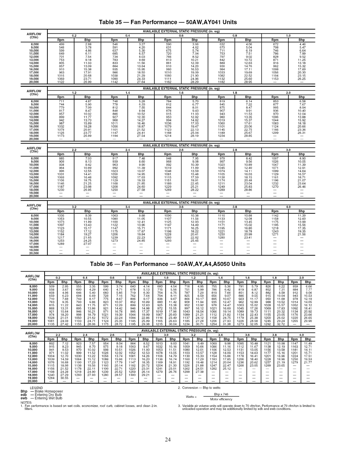
Table 35 -- Fan Performance -- 50AW,AY041 Units
AVAILABLE EXTERNAL STATIC PRESSURE (in. wg)
AIRFLOW 0.4 0.6
(Cfm)
8,000
9,000
10,000
11,000
12,000
13,000
14,000
15,000
16,000
17,000
18,000
19,000
20,000
AIRFLOW
(Cfm)
0.2
Rpm
499
548
599
649
701
753
805
857
918
963
1016
1069
1122
1.2
Rpm
711
744
779
817
857
899
942
987
1032
1078
1126
1173
8,000
9,000
10,000
11,000
12,000
13,000
14,000
15,000
16,000
17,000
18,000
19,000
20,000
Bhp
2.88
3.78
4.86
6.11
7,54
9.18
11.03
13.09
15.38
17,91
20.68
23.71
26.99
Rpm
546
581
837
885
734
783
833
884
835
986
1038
1090
1142
Bhp
3.27
4.20
5.30
6,57
8,03
9.69
11.56
13.64
15.95
18.50
21.29
24.33
27.64
Rpm
580
831
875
720
766
813
861
910
960
1010
1060
1111
1162
Bhp
3,68
4.62
5,74
7.04
8.52
10.21
12.09
14.20
16.53
19.09
21.90
24.96
28.29
Bhp
4.87
5.90
7.09
8,47
10.02
11.77
13.73
15.89
18,28
20.91
23.77
26.89
Rpm
748
778
812
848
886
827
968
1011
1056
1101
1147
1194
1.4
AVAILABLE EXTERNAL STATIC PRESSURE (in. w_)
1.6
Bhp
5.28
6.33
7,55
8.94
10.52
12,30
14.27
16.46
18,87
21,52
24,41
27,54
Bpm
784
812
844
878
915
953
984
1036
1079
1123
1168
1214
Rpm
832
870
711
753
787
842
889
936
984
1033
1082
1132
1182
0.8
Bhp
4.08
5,04
6.19
7.51
9.02
10.72
12.63
14.76
17.11
19.69
22.52
25.60
28.95
1.0
Rpm
672
708
746
768
828
871
818
862
1008
1058
1104
1153
Bhp
4.46
5,47
6.64
7.99
9.52
11.25
13.18
15.32
17.69
20.30
23.15
26.25
Bhp
5.70
8.77
8.01
9,43
11.03
12,82
14,82
17.03
19.47
22.13
25.04
28,19
AVAILABLE EXTERNAL STATIC PRESSURE (in. wg)
AIRFLOW
(Cfm) 2.4 2.6
2.2
Rpm
885
908
934
984
986
lO31
lO86
11o6
1146
1187
123o
8,000
9,000
10,000
11,000
12,000
13,000
14,000
15,000
16,000
17,000
18,000
19,000
20,000
Bhp
7,03
8,13
9,42
10.89
12.55
14.41
16,48
18.75
21.25
23.98
26.95
Rpm
817
839
863
982
lO23
1056
1092
1129
1168
1208
1250
Bhp
7,48
8,60
9.90
11.39
13.07
14.95
17.03
19.33
21.85
24.60
27.58
Bpm
819
845
875
907
943
98O
1019
1060
1101
1145
1189
1234
1.8
Bhp
6.14
7.22
8.47
9.91
11.53
13.35
15.37
17.61
20.06
22.75
25.67
28.85
2.0
Bpm
853
877
905
936
970
lOO6
lO44
lO83
1124
1166
12o9
Bhp
6,58
7.67
8.94
10.40
12.04
13.88
15.92
18.18
20.66
23.36
26.31
Bpm
948
968
992
1019
1048
1081
1115
1151
1189
1229
1269
Bhp
7.95
9.08
10.39
11.89
13.59
15.48
17.59
19.91
22.45
25.21
28.22
AVAILABLE EXTERNAL STATIC PRESSURE (in. wg)
AIRFLOW 3.4 3.6
(Cfm)
8,000
9,000
10,000
11,000
12,000
13,000
14,000
15,000
16,000
17,000
18,000
19,000
20,000
3.2
Rpm
1036
1053
1073
1097
1123
1152
1184
1217
1253
1289
Bpm
976
987
1020
1045
1074
1105
1136
1174
1211
1249
1289
2.8
Bhp
8.42
9.56
10.89
12.40
14.11
16.03
18.15
20.48
23.04
25.83
28.86
3.0
Bpm
lOO7
lO28
lO47
lO71
lO99
1129
1161
1196
1232
127o
Bhp
8.90
10.05
11.39
12.91
14.64
16.57
18.71
21.07
23.64
26.46
Bhp
9.39
10.55
11.89
13.43
15.17
17,12
19.27
21.65
24.25
27.07
Rpm
1063
1080
1100
1122
1147
1175
1206
1239
1273
Bhp
9.88
11.05
12.41
13.96
15.71
17.67
19.84
22.23
24.85
Rpm
1090
1107
1125
1147
1171
1188
1228
1260
1293
Bhp
10,38
11.58
12,93
14,49
16.25
18,22
20.41
22.82
25,45
Rpm
1116
1133
1151
1171
1195
1221
1250
1280
3.8
Bhp
10.88
12,08
13.45
15,02
16.80
18.78
20.99
23.41
4.0
Rpm
1142
1158
1175
1195
1218
1243
1271
Bhp
11.38
12,80
13.08
15,58
17.35
19,35
21,58
Table 36 -- Fan Performance -- 50AW,AY,A4,A5050 Units
AIRFLOW
(Cfm)
8,000
9,000
10,000
11,000
12,000
13,000
14,000
15,000
16,000
17,000
18,000
19,000
20,000
AVAILABLE EXTERNAL STATIC PRESSURE (in. wg)
0.2 0.4 0.6 0.8 1.0 1.2 1.4 1.6 1.8 2.0
Rpm Bhp Bpm Bhp Rpm Bhp Bpm Bhp Rpm Bhp Rpm Bhp Bpm Bhp Rpm Bhp Bpm Bhp Rpm Bhp
509 2.95 555 3.35 599 3.74 640 4.14 680 4.54 718 4.95 755 5.36 791 5.79 826 6.22 859 6.66
558 3.87 600 4.29 640 4.71 678 5.13 715 5.56 751 5.99 786 6.42 819 6.87 852 7.31 884 7.77
608 4.96 646 5.40 683 5.85 719 6.30 754 6.75 787 7.20 819 7.66 851 8.12 882 8,58 912 9.06
659 6.23 694 8.69 728 7.16 762 7,64 794 8.11 825 8.59 856 9.07 886 9,55 915 10.04 943 10.53
710 7,68 743 8.17 775 8.67 808 9.17 836 9,67 866 10.17 895 10.67 923 11.17 950 11.68 978 12.19
763 9.35 793 9.86 823 10.37 852 10.89 880 11.42 908 11.94 935 12.47 962 12.99 988 13.52 1014 14.05
815 11.22 843 11.75 871 12.29 899 12.83 925 13.38 952 13.92 978 14.47 1003 15.02 1028 15.57 1052 18.12
868 13.31 895 13.86 921 14.42 946 14.98 972 15.55 997 16.12 1021 18.69 1045 17.26 1069 17,83 1092 18.41
921 15.64 946 18.21 971 16.78 995 17,37 1019 17.96 1043 18.54 1066 19.14 1089 19.73 1111 20.32 1134 20.92
974 18.20 998 18.79 1021 19.39 1044 19.99 1067 20.60 1089 21.21 1112 21.82 1134 22.43 1155 23.05 1176 23.66
1028 21.01 1050 21.62 1072 22.24 1094 22.86 1118 23.48 1137 24.12 1158 24.75 1179 25.38 1200 26,02 1220 28.65
1081 24.08 1103 24.71 1124 25.35 1145 25,99 1165 28.63 1185 27.28 1208 27,93 1226 28.58 1245 29.24 1265 29.90
1135 27.42 1155 28.06 1175 28.72 1195 29.38 1215 30.04 1234 30.71 1254 31.38 1273 32.05 1292 32.72 -- --
AIRFLOW
(Cfm)
8,000
9,000
10,000
11,000
12,000
13,000
14,000
15,000
16,000
17,000
18,000
19,000
20,000
AVAILABLE EXTERNAL STATIC PRESSURE/in. w_!
2.2 2.4 2.6 2.8 3.0 3.2 3.4 3.6 3.8 4.0
Rpm Bhp Bpm Bbp Rpm Bhp Bpm Bbp Rpm Bhp Rpm Bhp Bpm Bbp Rpm Bhp Bpm Bbp Rpm Bhp
892 7.12 923 7.57 954 8,04 984 8,52 1013 9.00 1041 9.49 1069 9,98 1095 10,48 1121 10.98 1147 11.49
915 8,23 945 8.70 975 9.18 1003 9.67 1032 10,16 1059 10.66 1088 11.18 1112 11.67 1138 12.19 1163 12.71
941 9.53 970 10.02 998 10.51 1026 11.00 1053 11.51 1080 12.01 1108 12.53 1131 13.05 1158 13.58 1181 14.11
871 11.02 999 11.52 1026 12.02 1052 12.53 1078 13.05 1103 13.57 1128 14.09 1153 14.63 1177 15.18 1201 15.71
1004 12.70 1030 13.22 1056 13.74 1081 14.28 1108 14.79 1130 15.33 1154 15.86 1178 18.41 1201 16.96 1224 17.51
1039 14,59 1064 15.12 1088 15.66 1113 16.20 1136 16.74 1160 17,29 1183 17.85 1206 18.40 1228 18.98 1250 19,53
1076 16.68 1100 17.23 1123 17.79 1147 18,35 1169 18,91 1192 19.48 1214 20.04 1236 20.62 1257 21.19 1278 21.77
1115 18.98 1138 19.56 1160 20.14 1182 20.72 1204 21.30 1226 21.88 1247 22.47 1268 23.05 1289 23.65 -- --
1156 21.82 1178 22.11 1199 22.71 1220 23.31 1241 23.91 1262 24.81 1282 25.12 ......
1198 24.28 1218 24.90 1239 25.52 1259 26,14 1279 26.76 1299 27.38 ........
1240 27.29 1260 27.93 1280 28.57 1300 29.21 ............
1284 30.55 ..................
LEGEND 2. Conversion-- Bhp to watts:
Bhp -- Brake Horsepower
edb -- Entering Dry Bulb Watts = Bhp x 746
ewb -- Entering Wet Bulb Motor efficiency
NOTES:
1. Fan performance is based on wet coils, economizer, roof curb, cabinet losses, and clean 2-in.
filters. 3. Variable air volume units will operate down to 70 cfm/ton. Performance at 70 cfm/ton is limited to
unloaded operation and may be additionally limited by edb and ewb conditions.
24
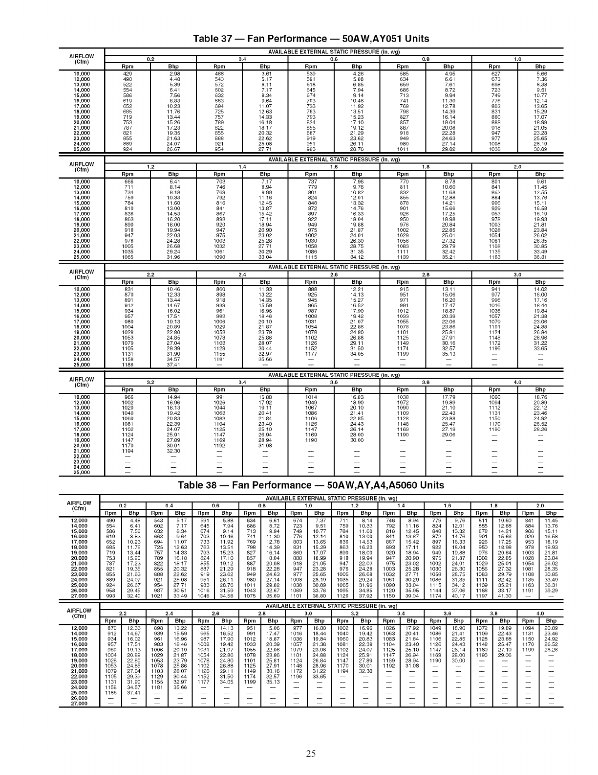
AIHI=LUW
(Cfm)
10,000
12,000
13,000
14,000
15,000
16,000
17,000
18,000
19,000
20,000
21,000
22,000
23,000
24,000
25,000
0.2
Rpm
429
49O
522
554
586
619
652
685
719
753
787
821
855
889
924
Bhp
2.98
4.48
5.39
6.41
7.56
8,83
10.23
11.76
13.44
15.26
17,23
19.35
21.63
24.07
26.67
Table 37 -- Fan Performance -- 50AW,AY051 Units
Rpm
488
543
572
6o2
632
663
694
725
757
789
822
855
888
921
954
AVAILABLE EXTERNAL STATIC PRESSURE (in. w_)
0.4 0.6 0.8
Bhp
3.61
5.17
6.11
7,17
8,34
9.64
11.07
12,63
14.33
16.18
18,17
20.32
22.62
25,08
27,71
Rpm
539
591
618
645
674
703
733
763
793
824
855
887
919
951
983
Bhp Rpm
4.26 585
5.88 634
6.85 659
7.94 686
9.14 713
10.46 741
11.92 769
13.51 798
15.23 827
17.10 857
19.12 887
21.29 918
23.62 949
26.11 980
28.76 1011
AVAILABLE EXTERNAL STATIC PRESSURE (in. wg)
AIHI=LUW
t_.4 )'^'m" 1.4 1.6 1.8
Bhp
6,41
8,14
9,18
10.33
11.60
13.00
14.53
16,20
18,00
19.94
22.03
24.28
26,68
29.24
31.96
1.2
Rpm
666
711
734
759
784
810
836
863
890
918
947
976
1005
1035
1065
10,000
12,000
13,000
14,000
15,000
16,000
17,000
18,000
19,000
20,000
21,000
22,000
23,000
24,000
25,000
Rpm
703
746
769
792
816
841
867
893
920
947
975
1003
1032
1061
1090
Bhp
7,17
8,94
9.99
11.16
12.45
13.87
15.42
17.11
18.94
20.90
23.02
25.28
27.71
30.29
33.04
Rpm
737
779
801
824
848
872
897
922
949
975
1002
1030
1058
1086
1115
Bhp Rpm
7.96 770
9,76 811
10.82 832
12,01 855
13,32 878
14.76 901
16.33 926
18.04 950
19.88 976
21.87 1002
24.01 1029
26.30 1056
28.75 1083
31.35 1111
34.12 1139
AVAILABLE EXTERNAL STATIC PRESSURE (in. wg)
AIHI=LUW
_L.,/ )"^'m" 2.2 2.4 2.6 2.8
Rpm
831
87o
891
912
934
957
980
lOO4
1028
1053
1079
1105
1131
1158
1186
10,000
12,000
13,000
14,000
15,000
16,000
17,000
18,000
19,000
20,000
21,000
22,000
23,000
24,000
25,000
Rpm
966
1002
1020
1040
1060
1081
1102
1124
1147
1170
1194
Rpm
860
898
918
939
961
983
1006
1029
1053
1078
1103
1129
1155
1181
Bhp
10.46
12.33
13.44
14.67
16.02
17.51
19.13
20.89
22.80
24.85
27,04
29.39
31.90
34.57
37.41
AIHPLUW
(Cfm)
10,000
12,000
13,000
14,000
15,000
16,000
17,000
18,000
19,000
20,000
21,000
22,000
23,000
24,000
25,000
Bhp
11.33
13.22
14.35
15.59
16.96
18.46
20.10
21.87
23.79
25.86
28.07
30.44
32.97
35.66
Rpm
888
925
945
965
987
1008
1031
1054
1078
1102
1126
1152
1177
AIHPLUW
(Cfm)
12,000
14,000
15,000
16,000
17,000
18,000
19,000
20,000
21,000
22,000
23,000
24,000
25,000
26,000
27,000
Bhp
12.21
14.13
15.27
16.52
17.90
19.42
21.07
22.86
24.80
26.88
29.11
31.50
34.05
Rpm
915
951
971
991
1012
1033
1055
1078
1101
1125
1149
1174
1199
AVAILABLEEXTERNALSTATICPRESSURE(in.w_)
3.2 3.4 3.6 3.8
Bhp
14.94
16.96
18,13
19,42
20.83
22.39
24.07
25.91
27.89
30.01
32.30
Rpm
991
1026
1044
1063
1083
1104
1125
1147
1169
1192
Bhp
15.88
17.92
19.11
20.41
21.84
23.40
25.10
26.94
28.94
31.08
Rpm
1014
1049
1067
1086
1106
1126
1147
1169
1190
Bhp
16.83
18,90
20,10
21.41
22,85
24,43
26.14
28,00
30,00
Rpm
1038
1072
1090
1109
1128
1148
1169
1190
Bhp
4.95
6.61
7.61
8.72
9.94
11.30
12.78
14.39
16.14
18.04
20.08
22.28
24.63
27.14
29.82
Bhp
8.78
10.60
11.68
12.88
14.21
15.66
17.25
18.98
20.84
22.85
25.01
27.32
29.79
32.42
35.21
Bhp
13.11
15.06
16.20
17.47
18.87
20.39
22.06
23.86
25.81
27.91
30.16
32.57
35.13
Rpm
627
673
698
723
749
776
803
831
860
888
918
947
977
1008
1038
1.0
Bhp
5.66
7.36
8.38
9.51
10.77
12.14
13.65
15.29
17.07
18.99
21.05
23.28
25.65
28.19
30.89
Bhp
17.79
19.89
21.10
22.43
23.88
25.47
27.19
29.06
Rpm
801
841
862
884
906
929
953
978
1003
1028
1054
1081
1108
1135
1163
2.0
Bhp
9.61
11.45
12.55
13.76
15.11
16.58
18.19
19.93
21.81
23.84
26.02
28.35
30.85
33.49
36.31
3.0
Rpm Bhp
941 14.02
977 16.00
996 17.16
1016 18.44
1036 19.84
1057 21.38
1079 23.06
1101 24.88
1124 26.84
1148 28.96
1172 31.22
1196 33.65
4.0
Rpm Bhp
1060 18.76
1094 20.89
1112 22.12
1131 23.46
1150 24.92
1170 26.52
1190 28.26
Table 38 -- Fan Performance -- 50AW,AY,A4,A5060 Units
AVAILABLE EXTERNAL STATIC PRESSURE (in. wg)
0.2 0.4 0.6 0.8 1.0 1.2 1.4 1.6 1.8 2.0
Rpm Bhp Rpm Bhp Rpm Bhp Rpm Bhp Rpm Bhp Rpm Bhp Rpm Bhp Rpm Bhp Rpm Bhp Rpm Bhp
490 4.48 543 5.17 591 5.88 634 6,61 674 7.37 711 8.14 746 8.94 779 9.76 811 10.60 841 11,45
554 6.41 602 7.17 645 7.94 686 8,72 723 9.51 759 10.33 792 11.16 824 12.01 855 12.88 884 13.76
586 7.56 632 8.34 674 9.14 713 9.94 749 10.77 784 11.60 816 12.45 848 13.32 878 14.21 906 15.11
619 8.83 663 9.64 703 10.46 741 11.30 776 12.14 810 13.00 841 13.87 872 14.76 901 15.66 929 16.58
652 10.23 694 11.07 733 11.92 769 12.78 803 13.65 836 14,53 867 15.42 897 16.33 926 17.25 953 18.19
685 11.76 725 12.63 763 13.51 798 14.39 831 15.29 863 16.20 893 17.11 922 18.04 950 18,98 978 19.93
719 13.44 757 14.33 793 15.23 827 16.14 860 17.07 890 18,00 920 18.94 949 19,88 976 20.84 1003 21.81
753 15.26 789 16.18 824 17.10 857 18,04 888 18.99 918 19.94 947 20.90 975 21.87 1002 22.85 1028 23.84
787 17.23 822 18.17 855 19,12 887 20.08 918 21.05 947 22.03 975 23.02 1002 24.01 1029 25.01 1054 26.02
821 19.35 855 20.32 887 21.29 918 22.28 947 23.28 976 24.28 1003 25.28 1030 26.30 1056 27,32 1081 28.35
855 21.63 888 22.62 919 23.62 949 24.63 977 25.65 1005 26.68 1032 27.71 1058 28,75 1083 29.79 1108 30.85
889 24.07 921 25.08 951 26.11 980 27,14 1008 28.19 1035 29.24 1061 30.29 1086 31.35 1111 32.42 1135 33.49
924 26.67 954 27.71 983 28.76 1011 29.82 1038 30.89 1065 31.96 1090 33.04 1115 34.12 1139 35.21 1163 36.31
958 29.45 987 30.61 1016 31.59 1043 32.67 1069 33.76 1095 34.85 1120 35.95 1144 37.06 1168 38.17 1191 39.29
993 32.40 1021 33.49 1048 34.58 1075 35.69 1101 36.80 1126 37.92 1150 39.04 1174 40.17 1197 41.30 -- --
AVAILABLE EXTERNAL STATIC PRESSURE (in. wg)
AIRFLOW
(Cfm) 2.2 2.4 2.6 2.8 3.0 3.2 3.4 3.6 3.8 4.0
12,000
14,000
15,000
16,000
17,000
18,000
19,000
20,000
21,000
22,000
23,000
24,000
25,000
26,000
27,000
20.89
23.46
24.92
26.52
28.26
25
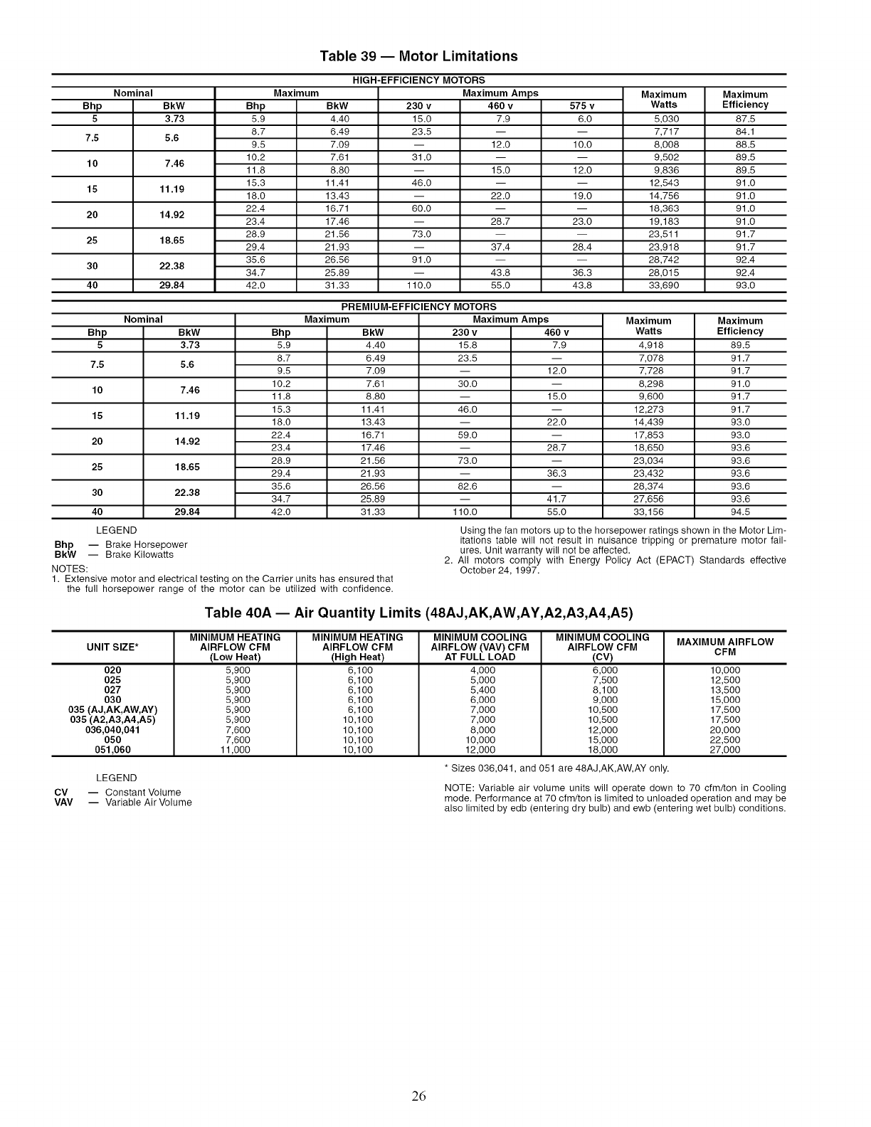
Table 39 -- Motor Limitations
HIGH-EFFICIENCY MOTORS
Nominal Maximum Maximum Amps Maximum Maximum
Bhp BkW Bhp BkW 230 v 460 v 575 v Watts Efficiency
5 3.73 5.9 4.40 15.0 7.9 6.0 5,030 87.5
8.7 6.49 23.5 -- -- 7,717 84.1
7.5 5.6 9.5 7.09 -- 12.0 10.0 8,008 88.5
10.2 7.61 31.0 -- -- 9,502 89.5
10 7.46 11.8 8.80 -- 15.0 12.0 9,836 89.5
15.3 11.41 46.0 -- -- 12,543 91.0
15 11.19 18.0 13.43 -- 22.0 19.0 14,756 91.0
22.4 16.71 60.0 -- -- 18,363 91.0
20 14.92 23.4 17.46 -- 28.7 23.0 19,183 91.0
28.9 21.56 73.0 -- -- 23,511 91.7
25 18.65 29.4 21.93 -- 37.4 28.4 23,918 91.7
35.6 26.56 91.0 -- -- 28,742 92.4
30 22.38 34.7 25.89 -- 43.8 36.3 28,015 92.4
40 29.84 42.0 31.33 110.0 55.0 43.8 33,690 93.0
PREMIUM-EFFICIENCY MOTORS
Nominal
Bhp
5
7.5
10
15
20
25
30
40
BkW
3.73
5.6
7.46
11.19
14.92
18.65
22.38
29.84
Bhp
5.9
8.7
9.5
10.2
11.8
15.3
18.0
22.4
23.4
28.9
29.4
35.6
34.7
42.0
Maximum
BkW
4.40
6.49
7.09
7.61
8.80
11.41
13.43
16.71
17.46
21.56
21.93
26.56
25.89
31.33
LEGEND
-- Brake Horsepower
-- Brake Kilowatts
Maximum Amps
230 v 460 v
15.8 7.9
23.5
-- 12.0
30.0
-- 15.0
46.0
-- 22.0
59.0
-- 28.7
73.0
-- 36.3
82.6
-- 41.7
110.0 55.0
Maximum
Watts
4,918
7,078
7,728
8,298
9,600
12,273
14,439
17,853
18,650
23,034
23,432
28,374
27,656
33,156
Maximum
Efficiency
89.5
91.7
91.7
91.0
91.7
91.7
93.0
93.0
93.6
93.6
93.6
93.6
93.6
94.5
Bhp
BkW
NOTES:
1. Extensive motor and electrical testing on the Carrier units has ensured that
the full horsepower range of the motor can be utilized with confidence.
Using the fan motors up to the horsepower ratings shown in the Motor Lim-
itations table will not result in nuisance tripping or premature motor fail-
ures. Unit warranty will not be affected.
2. All motors comply with Energy Policy Act (EPACT) Standards effective
October 24, 1997.
Table 40A -- Air Quantity Limits (48AJ,AK,AW,AY,A2,A3,A4,A5)
MAXIMUM AIRFLOW
UNIT SIZE* CFM
020
025
027
030
035 (AJ,AK,AW,AY)
035(A2,A3,A4,A5)
036,040,041
050
051,060
LEGEND
CV -- Constant Volume
VAV -- Variable Air Volume
MINIMUM HEATING
AIRFLOW CFM
(Low Heat)
5,900
5,900
5,900
5,900
5,900
5,900
7,600
7,600
11,000
MINIMUM HEATING
AIRFLOW CFM
(High Heat)
6,100
6,100
6,100
6,100
6,100
10,100
10,100
10,100
10,100
MINIMUM COOLING
AIRFLOW (VAV) CFM
AT FULL LOAD
4,000
5,000
5,400
6,000
7,000
7,000
8,000
10,000
12,000
MINIMUM COOLING
AIRFLOW CFM
(CV)
6,000
7,500
8,100
9,000
10,500
10,500
12,000
15,000
18,000
* Sizes 036,041, and 051 are 48AJ,AK,AW, AY only.
10,000
12,500
13,500
15,000
17,500
17,500
20,000
22,500
27,000
NOTE: Variable air volume units will operate down to 70 cfm/ton in Cooling
mode. Performance at 70 cfm/ton is limited to unloaded operation and may be
also limited by edb (entering dry bulb) and ewb (entering wet bulb) conditions.
26
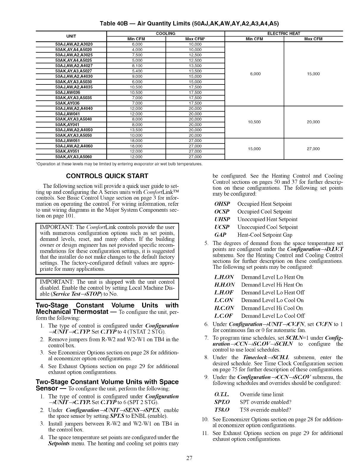
Table 40B -- Air Quantity Limits (50AJ,AK,AW,AY,A2,A3,A4,A5)
UNIT COOLING ELECTRIC HEAT
Min CFM Max CFM
50AJ,AW, A2,A3020
50A K,AY, A4,A5020
50AJ,AW, A2,A3025
50A K,AY, A4,A5025
50AJ,AW, A2,A4027
50A K,AY, A3,A5027
50AJ,AW, A2,A4030
50A K,AY, A3,A5030
50AJ,AW, A2,A4035
50AJ,AW036
50A K,AY, A3,A5035
50AK,AY036
50AJ,AW, A2,A4040
50AJ,AW041
50A K,AY, A3,A5040
50AK,AY041
50AJ,AW, A2,A4050
50A K,AY, A3,A5050
50AJ,AW051
50AJ,AW, A2,A4060
50AK,AY051
50A K,AY, A3,A5060
Min CFM
6,000
4,000
7,500
5,000
8,100
5,400
9,000
6,000
10,500
10,500
7,000
7,000
12,000
12,000
8,000
8,000
13,500
10,000
18,000
18,000
12,000
12,000
Max CFM*
10,000
10,000
12,500
12,500
13,500
13,500
15,000
15,000
17,500
17,500
17,500
17,500
20,000
20,000
20,000
20,000
20,000
20,000
27,000
27,000
27,000
27,000
*Operation at these levels may be limited by entering evaporator air wet bulb temperatures.
6,000
10,500
15,000
15,000
20,000
27,000
CONTROLS QUICK START
The following section will provide a quick user guide to set-
ting up and configuring the A Series units with (_l_fortLink TM
controls. See Basic Control Usage section on page 3 for infor-
mation on operating the control. For wiring information, refer
to unit wiring diagrams in the Major System Components sec-
tion on page 101.
IMPORTANT: The (_nfortLink controls provide the user
with numerous configuration options such as set points,
demand levels, reset, and many others. If the building
owner or design engineer has not provided specific recom-
mendations for these configuration settings, it is suggested
that the installer do not make changes to the default factory
settings. The factory-configured default values are appro-
priate for many applications.
IMPORTANT: The unit is shipped with the unit control
disabled. Enable the control by setting Local Machine Dis-
able (Service Test--+STOP) to No.
Two-Stage Constant Volume Units with
Mechanical Thermostat E To configure the unit, per-
form the following:
1. The type of control is configured under Configuration
--+UNIT--+C. TYP Set C TYP to 4 (TSTAT 2 STG).
2. Remove jumpers from R-W2 and W2-W1 on TB4 in the
control box.
3. See Economizer Options section on page 28 for addition-
al economizer option configurations.
4. See Exhaust Options section on page 29 for additional
exhaust option configurations.
Two-Stage Constant Volume Units with Space
Sensor ETo configure the unit, perform the following:
1. The type of control is configured under (bnfiguration
--+UNIT--+C. TYP. Set C TYP to 6 (SPT 2 STG).
2. Under Configuration--_UNIT--+SENS--+SPT.S, enable
the space sensor by setting SPT.S to ENBL (enable).
3. Install jumpers between R-W2 and W2-W1 on TB4 in
the control box.
4. The space temperature set points are configured under the
Setpoints menu. The heating and cooling set points may
5.
6.
7.
10.
11.
be configured. See the Heating Control and Cooling
Control sections on pages 50 and 37 for further descrip-
tion on these configurations. The following set points
may be configured:
OHSP Occupied Heat Setpoint
O(SP Occupied Cool Setpoint
UHSP Unoccupied Heat Setpoint
U_SP Unoccupied Cool Setpoint
GAP Heat-Cool Setpoint Gap
The degrees of demand from the space temperature set
points are configured under the (bnfiguration--+D.LET
submenu. See the Heating Control and Cooling Control
sections for further description on these configurations.
The following set points may be configured:
L.H.ON
H.H.ON
L.H.OF
L.C.ON
H.C.ON
L.C.OF
Demand Level Lo Heat On
Demand Level Hi Heat On
Demand Level Lo Heat Off
Demand Level Lo Cool On
Demand Level Hi Cool On
Demand Level Lo Cool Off
Under (bnfiguration-+UNIT_'V..FN, set CV.FN to 1
for continuous fan or 0 for automatic fan.
To program thne schedules, set SCH.N=I under (bnfig-
uration_CCN-+SCOV--+SCH.N to configure the
control to use local schedules.
8. Under the Timeclock-+SCI-I.L submenu, enter the
desired schedule. See Time Clock Configuration section
on page 75 for further description of these configurations.
9. Under the Configuration_'CN-cSC.OV submenu, the
following schedules and overrides should be configured:
O.T.L Ovemde time limit
SPT.O SPT override enabled?
7"58.0 T58 ovemde enabled?
See Economizer Options section on page 28 for addition-
al economizer option configurations.
See Exhaust Options section on page 29 for additional
exhaust option configurations.
27
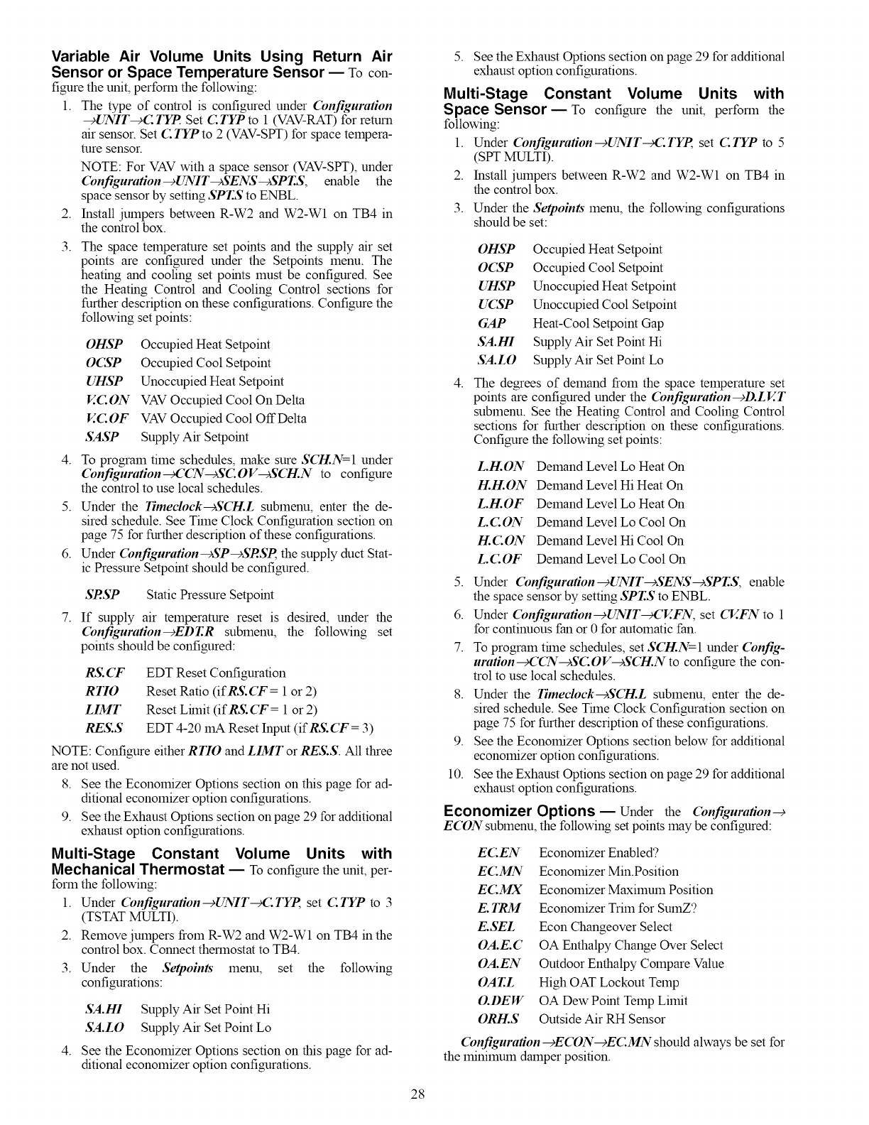
Variable Air Volume Units Using Return Air
Sensor or Space Temperature Sensor -- To con-
figure the unit, perform the following:
1. The type of control is configured under Cbnfiguration
--_UNIT-+C TYP Set C TYP to 1 (VAV-RAT) for return
air sensor. Set C !TP to 2 (VAV-SPT) for space tempera-
ture sensor.
2.
NOTE: For VAV with a space sensor (VAV-SPT), under
Configuration-+UNIT-+SENS-+SPT.S, enable the
space sensor by setting SPT.S to ENBL.
Install jumpers between R-W2 and W2-Wl on TB4 in
the control box.
3. The space temperature set points and the supply air set
points are configured under the Setpoints menu. The
heating and cooling set points must be configured. See
the Heating Control and Cooling Control sections for
further description on these configurations. Configure the
following set points:
4.
OHSP
OCNP
UHSP
EC.ON
V.C OF
SASP
Occupied Heat Setpoint
Occupied Cool Setpoint
Unoccupied Heat Setpoint
VAV Occupied Cool On Delta
VAV Occupied Cool OffDelta
Supply Air Setpoint
To program time schedules, make sure SCI-LN=I under
Configuration--cCCN--cSC:OV--cSCH.N to configure
the control to use local schedules.
5. Under the Timeclock-+SCI-I.L submenu, enter the de-
sired schedule. See Time Clock Configuration section on
page 75 for further description of these configurations.
6. Under Configuration-+SP-+SRSP the supply duct Stat-
ic Pressure Setpoint should be configured.
7.
SRSP Static Pressure Setpoint
If supply air temperature reset is desired, under the
Configuration-+EDT.R submenu, the following set
points should be configured:
RS. CF
R TIO
LIMT
RES.S
EDT Reset Configuration
Reset Ratio (ifRS.CF = 1 or 2)
Reset Lhnit (ifRS.CT = 1 or 2)
EDT 4-20 mA Reset Input (ifRS. CT = 3)
NOTE: Configure either RTIO and LIMT or RES.S. All three
are not used.
8. See the Economizer Options section on this page for ad-
ditional economizer option configurations.
9. See the Exhaust Options section onpage 29 for additional
exhaust option configurations.
Multi-Stage Constant Volume Units with
Mechanical Thermostat EToconfigure the unit, per-
form the following:
1. Under Configuration-+UNIT_C TYp set C:TYP to 3
(TSTAT MULTI).
2. Remove jumpers from R-W2 and W2-W1 on TB4 in the
control box. Connect thermostat to TB4.
3. Under the Setpoints menu, set the following
configurations:
4.
SA.HI Supply Air Set Point Hi
SA.LO Supply Air Set Point Lo
See the Economizer Options section on this page for ad-
ditional economizer option configurations.
5. See the Exhaust Options section on page 29 for additional
exhaust option configurations.
Multi-Stage Constant Volume Units with
Space Sensor E To configure the unit, perform the
following:
1. Under Configuration-+UNIT_C TYp set C:TYP to 5
(SFr MULTI).
2. Install jumpers between R-W2 and W2-Wl on TB4 in
the control box.
3. Under the Setpoints menu, the following configurations
should be set:
4.
OHSP
OCSP
UHSP
UCSP
GAP
SA.HI
SA.LO
Occupied Heat Setpoint
Occupied Cool Setpoint
Unoccupied Heat Setpoint
Unoccupied Cool Setpoint
Heat-Cool Setpoint Gap
Supply Air Set Point Hi
Supply Air Set Point Lo
The degrees of demand from the space temperature set
points are configured under the Cbnfiguration-+D.LV.T
submenu. See the Heating Control and Cooling Control
sections for further description on these configurations.
Configure the following set points:
5.
L.H.ON
H.H.ON
L.H.OF
L.C.ON
H.C.ON
LC.OF
Demand Level Lo Heat On
Demand Level Hi Heat On
Demand Level Lo Heat On
Demand Level Lo Cool On
Demand Level Hi Cool On
Demand Level Lo Cool On
6.
7.
Under Cbnfiguration--+UNIT--+SENS--+SPT.S, enable
the space sensor by setting SPT.S to ENBL.
Under Cbnfiguration-+UNIT_,CV..FN, set CV..FN to 1
for continuous fan or 0 for automatic fan.
To program thne schedules, set SCI-LN=I under Cbnfig-
uration_,CCN-+SCOV-+SCI-I.N to configure the con-
trol to use local schedules.
8. Under the Timeclock-+SCI-I.L submenu, enter the de-
sired schedule. See Thne Clock Configuration section on
page 75 for further description of these configurations.
9. See the Economizer Options section below for additional
economizer option configurations.
10. See the Exhaust Options section on page 29 for additional
exhaust option configurations.
Economizer Options _ Under the Cbnfiguration--+
ECON submenu, the following set points ]nay be configured:
EC.EN
EC.MN
EC.MX
E. TRM
E.SEL
OA.E. C
OA.EN
OAT.L
O.DEW
ORH.S
Economizer Enabled?
Economizer Min.Position
Economizer Maximum Position
Economizer Trim for SumZ?
Econ Changeover Select
OA Enthalpy Change Over Select
Outdoor Enthalpy Compare Value
High OAT Lockout Temp
OA Dew Point Temp Limit
Outside Air RH Sensor
Configuration--_ECON-+EC.MN should always be set for
the minimum damper position.
28
Indoor Air Quality (IAQ) Options
DEMAND CONTROL VENTILATION -- Under (bnfigu-
ration-+IAQ-+DCV.C, the following configuration parame-
ters should be set to establish the minflnum and maximum
points for outdoor air damper position during demand control
ventilation (DCV):
ECMN Economizer Min.Position
IAQ.M IAQ Demand Vent Min.Pos.
Configuration -+IAQ-+DCV..C-+IAQ.M is used to set the
absolute lninimum vent position (or maximum reset) under
DCV.
Configuration-+IAQ-+DCV.C-+EC.MN is used to set the
minimum damper position (or with no DCV reset). This is also
referenced in the economizer section.
Exhaust Options EThe A Series units can be config-
ured with constant volume 2-stage power exhaust or modulat-
ing power exhaust. The following exhaust options should be
configured.
Configuration-+BP-+BECF=l (Two-Stage Exhaust
-- For two-stage exhaust, under the Configuration
--+BP submenu, configure the following:
BRP1 Power Exhaust On Setp. 1
BRP2 Power Exhaust On Setp.2
Con.figuration --+BP--+BE CF=2 (Modulating Power Exhaust
-- For modulating exhaust, in the Configuration-+
BP submenu, configure the following:
BRSP Building Pressure Setp.
Programming Operating Schedules EThe
(_,fortLink TM controls will accolmnodate up to eight differ-
ent schedules (Periods 1 through 8), and each schedule is
assigned to the desired days of the week. Each schedule
includes an occupied on and off tflne. As an example, to set an
occupied schedule for 8 AM to 5 PM for Monday through
Friday, the user would set days Monday through Friday to ON
for Period 1. Then the user would configure the Period 1
Occupied From point to 08:00 and the Period 1 Occupied To
point to 17:00. To create a different weekend schedule, the user
would use Period 2 and set days Saturday and Sunday to ON
with the desired Occupied On and Ofttimes. To create a sched-
ule, perform the following procedure:
NOTE: By default, the tflne schedule periods are progralmned
for 24 hours of occupied operation.
1. Scroll to the Configuration mode, and select CCN
CONFIGURATION (('(Pc). Scroll clown to the Schedule
Number (Configuration _CCN-+SC OV-+SCI-I.N). If
password protection has been enabled, the user will be
prompted to enter the password before any new data is
accepted. S(7-!.N has a range of 0 to 99. The default val-
ue is 1. A value of 0 is always occupied, and the unit will
control to its occupied set points. A value of 1 means the
unit will follow a local schedule, and a value of 65 to 99
means it will follow a CCN schedule. Schedules 2 to 64
are not used as the control only supports one internal/lo-
cal schedule. If one of the 2 to 64 schedules is configured,
then the control will force the number back to 1. Make
sure the value is set to 1 to use a local schedule.
2. Enter the Time Clock mode. Scroll down to the LOCAL
TIME SCHEDULE (SCH.L) sub-mode, and press
ENTER. Period 1 (PER.l) will be displayed. Press EN-
TER to configure Period 1.
3. Configure the beginning of the occupied thne period for
Period 1 (O('(). Scroll down to O('(' and press ENTER
to go into Edit mode. The first two digits of the 00.00 will
start flashing. Use the UP or DOWN key to display the
correct value for hours, in 24-hour (military) time. Press
ENTER and hour value is saved and the minutes digits
will start flashing. Use the same procedure to display and
save the desired minutes value. Press ESCAPE.
4. Configure the unoccupied time for period 1 (UNO.
Scroll down to UNC and press ENTER to go into Edit
mode. The first two digits of the 00.00 will start flashing.
Use the UP or DOVv2',Ikey to display the correct value for
hours, in 24-hour (military) time. Press ENTER and hour
value is saved and the minutes digits will start flashing.
Use the same procedure to display and save the desired
minutes value. Press ESCAPE.
5. Scroll to DAYS and press ENTER. Scroll down to the
MON point. This point indicates if schedule 1 applies to
Monday. Use the ENTER colrnnand to go into Edit
mode, and use the UP or DOWN key to change the dis-
play to YES or NO. Scroll down through the rest of the
days and apply schedule 1 where desired. The schedule
can also be applied to a holiday. Press ESCAPE.
6. The first schedule is now complete. If a second schedule
is needed, such as for weekends or holidays, scroll down
and repeat the entire procedure for period 2 (PER.2). If
additional schedules are needed, repeat the process for as
many as are needed. Eight schedules are provided.
SERVICE TEST
General -- The units are equipped with a Service Test fea-
ture, which is intended to allow a service person to force the
unit into different modes of operation to test them. To use this
feature, enter the Service Test category on the local display and
place the unit into the test mode by changing Service
Test-+TESTfrom OFF to ON. The display will prompt for the
password before allowing any change. The default password is
1111. Once the unit enters the Service Test mode, the unit will
shut down all current modes.
TEST-- The TEST colranand turns the unit off (hard stop)
and allows the unit to be put in a manual control mode.
STOP- The STOP colranand completely disables the unit
(all outputs turn off ilranediately). Once in this mode, nothing
can ovemde the unit to turn it on. The controller will ignore all
inputs and colmnands.
S.STP Setting Soft Stop to YES turns the unit off in an
orderly way, honoring any time guards currently in effect.
FAN.F-- By turning the FAN FORCE on, the supply fan is
turned on and will operate as it normally would, controlling
duct static pressure on VAV applications or just energizing the
fan on CV applications. To remove the force, press ENTER
and then press the UP and DOWN arrows shnultaneously.
E4.CH-- The 4-Inch Filter Change Mode variable is used to
service the unit when 4-in. filters are used. When the filters
need to be changed, set Service Test-+E4. (7-/= YES. The unit
will be placed in Service Test mode and the economizer will
move to the 40% open position to facilitate removal of the 4-in.
filters. After the filters have been changed, set Service
Test-+E4.CI-I= NO to return the unit to normal operation.
The remaining categories: INDP, FANS, COOL, and
HEAT are sub-modes with separate items and functions. See
Table 41.
Service Test Mode Logic -- Operation in the Service
Test mode is sub-mode specific except for the Independent sub-
mode. Leaving the sub-mode while a test is being performed
and attempting to start a different test in the new sub-mode will
cause the previous test to terminate. When this happens, the
new request will be delayed for 5 seconds. For example, if com-
pressors were turned on under the COOL sub-mode, any at-
tempt to turn on heating stages within the HEAT sub-mode
would ilranediately turn offthe compressors and, 5 seconds lat-
er, the controller would honor the requested heat stages.
29
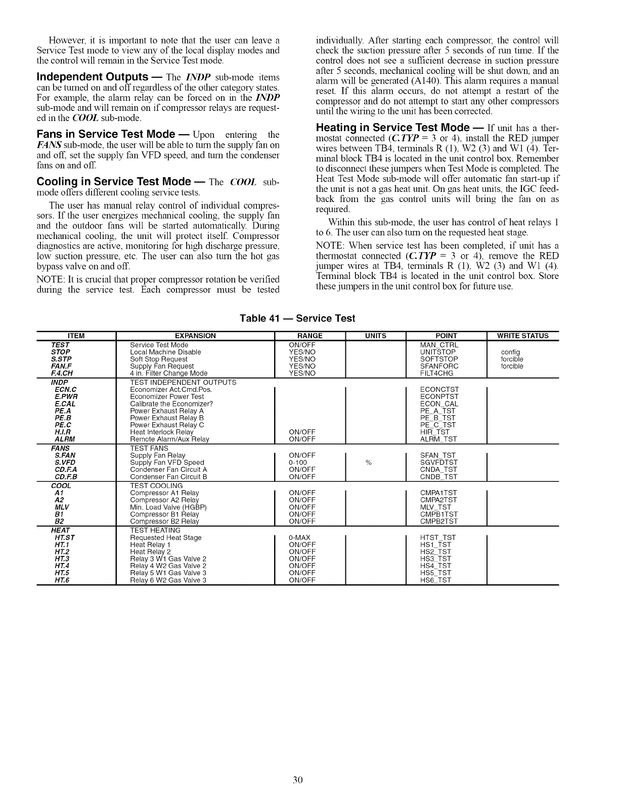
Howevecit isimportanttonotethattheusercanleavea
ServiceTest]nodetoviewanyofthelocaldisplaymodesand
thecontrolwillremaininthe Service Test ]node.
Independent Outputs -- The INDP sub-mode items
can be turned on and off regardless of the other category states.
For example, the alarm relay can be forced on in the INDP
sub-mode and will remain on if compressor relays are request-
ed in the COOL sub-mode.
Fans in Service Test Mode -- Upon entering the
FANS sub-mode, the user will be able to turn the supply fan on
and off, set the supply fan VFD speed, and turn the condenser
fans on and off.
Cooling in Service Test Mode -- The COOL sub-
]node offers different cooling service tests.
The user has manual relay control of individual compres-
sors. If the user energizes mechanical cooling, the supply fan
and the outdoor fans will be started automatically. During
mechanical cooling, the unit will protect itself. Compressor
diagnostics are active, monitoring for high discharge pressure,
low suction pressure, etc. The user can also turn the hot gas
bypass valve on and off.
NOTE: It is crucial that proper compressor rotation be verified
during the service test. Each compressor must be tested
individually. After starting each compressor, the control will
check the suction pressure after 5 seconds of run time. If the
control does not see a sufficient decrease in suction pressure
after 5 seconds, mechanical cooling will be shut down, and an
alarm will be generated (A140). This alarm requires a manual
reset. If this alarm occurs, do not attempt a restart of the
compressor and do not attempt to start any other compressors
until the wiring to the unit has been corrected.
Heating in Service Test Mode _ If unit has ather-
mostat connected (C TYP = 3 or 4), install the RED jumper
wires between TB4, terminals R (1), W2 (3) and Wl (4). Ter-
minal block TB4 is located in the unit control box. Remember
to disconnect these jumpers when Test Mode is completed. The
Heat Test Mode sub-mode will offer automatic fan start-up if
the unit is not a gas heat unit. On gas heat units, the IGC feed-
back from the gas control units will bring the fan on as
required.
Within this sub-mode, the user has control of heat relays 1
to 6. The user can also turn on the requested heat stage.
NOTE: When service test has been completed, if unit has a
thermostat connected (CTYP = 3 or 4), remove the RED
jumper wires at TB4, terminals R (1), W2 (3) and Wl (4).
Terminal block TB4 is located in the unit control box. Store
these jumpers in the unit control box for future use.
ITEM
TEST
STOP
S.STP
FAN.F
F.4.CH
INDP
ECN. C
E.PWR
E.CAL
PE.A
PE.B
PE.C
H.I.R
ALRM
FANS
S.FAN
S. VFD
CD.F.A
CD.F.B
COOL
A1
A2
MLV
B1
B2
HEAT
HT.ST
HT.1
HT.2
HT.3
HT.4
HT.5
HT.6
Table 41 -- Service Test
EXPANSION
Service Test Mode
Local Machine Disable
Soft Stop Request
Supply Fan Request
4 in. Filter Change Mode
TEST INDEPENDENT OUTPUTS
Economizer Act.Cmd.Pos.
Economizer Power Test
Calibrate the Economizer?
Power Exhaust Relay A
Power Exhaust Relay B
Power Exhaust Relay C
Heat Interlock Relay
Remote Alarm/Aux Relay
TEST FANS
Supply Fan Relay
Supply Fan VFD Speed
Condenser Fan Circuit A
Condenser Fan Circuit B
TEST COOLING
Compressor A1 Relay
Compressor A2 Relay
Min. Load Valve (HGBP)
Compressor B1 Relay
Compressor B2 Relay
TEST HEATING
Requested Heat Stage
Heat Relay 1
Heat Relay 2
Relay 3 W1 Gas Valve 2
Relay 4 W2 Gas Valve 2
Relay 5 W1 Gas Valve 3
Relay 6 W2 Gas Valve 3
RANGE UNITS POINT WRITE STATUS
ON/OFF MAN CTRL
YES/NO UNIT-STOP config
YES/NO SOFTSTOP forcible
YES/NO SFANFORC forcible
YES/NO FILT4CHG
ON/OFF
ON/OFF
ON/OFF
0-100
ON/OFF
ON/OFF
ON/OFF
ON/OFF
ON/OFF
ON/OFF
ON/OFF
O-MAX
ON/OFF
ON/OFF
ON/OFF
ON/OFF
ON/OFF
ON/OFF
%
ECONCTST
ECONPTST
ECON CAL
PE A TST
PE-BTST
PE C TST
HIR TST
ALR-MTST
I SFAN TST
SGVF-DTST
CNDA TST
CNDB TST
I CMPA1TST
CMPA2TST
MLV TST
CMP-B1TST
CMPB2TST
HTST TST
HSl TST
HS2 TST
HS3TST
HS4 TST
HS5 TST
HS6TST
3O
THIRD PARTY CONTROL
Thermostat EThe method of control would be through
the thermostat inputs:
Y1 = first stage cooling
Y1 and Y2 = first and second stage cooling
Wl = first stage heating
Wl and W2 = first and second stage heating
G = supply fan
Alarm Output E The alarm output TB4-7 and 8, will pro-
vide relay closure whenever the unit is under an alert or alarm
condition.
Remote Switch _The remote switch may be configured
for three different functions. Under Configuration --+UNIT, set
RM. (T" to one of the following:
0 = no remote switch
1 = occupied/unoccupied switch
2 = start!stop switch
3 = occupancy ovemde switch
With RM. CF set to 1, no time schedules are followed and
the unit follows the remote switch only in determining the state
of occupancy.
With RM. CF set to 2, the remote switch can be used to shut
down and disable the unit, while still honoring tflne guards on
compressors. Time schedules, internal or external, may be run
simultaneously with this configuration.
With RM.CF set to 3, the remote input may override an
unoccupied state and force the control to go into occupied
mode. As with the start/stop configuration, an internal or exter-
nal time schedule may continue to control occupancy when the
switch is not in effect.
Under (bnfiguration-+SW.LG---_RMI.L, the remote occu-
pancy switch can be set to either anormally open or normally
closed switch input. Normal is defined as either unoccupied, start
or "not currently overridden," respective to the RM.CF
configuration.
VFD Control _On VFD equipped supply fans, supply
duct static pressure control may be left under unit control or be
externally controlled. To control a VFD externally with a 4 to
20 mA signal, set SRRS to 4, under the Configuration--+SP
menu. This will set the reset to VFD control. When SRRS = 4,
the static pressure reset function acts to provide direct VFD
speed control where 4 mA = 0% speed and 20 mA = 100%
(SRMN and SRMX will ovemde). Note that SRCF must be
set to 1 (VFD Control) prior to configuring SRRS = 4. Failure
to do so could result in damage to ductwork due to overpressur-
ization. In effect, this represents a speed control signal "pass
through" under normal operating circumstances. The
(bnfortLink controller ovemdes the third party signal for crit-
ical operation situations, most notably smoke and fire control.
Wire the input to the controls expansion module (CEM) using
TB-11 and 12. An optional CEM board is required.
See Appendix C and the VFD literature supplied with the unit
for VFD configurations and field wiring connections to the VFD.
Supply Air Reset -- With the installation of the CEM,
the (_mfortLink controller is capable of accepting a 4 to
20 mA signal, to reset the supply-air temperature up to a maxi-
mum of 20 E See VFD Control section above.
Demand Limit Control _The term "demand limit
control" refers to the restriction of the machine's mechanical
cooling capacity to control the amount of power that a machine
may use.
Demand limiting using mechanical control is possible via two
means:
Two discrete inputs tied to demand lhnit set point percentages.
OR
A 4 to 20 mA input that can reduce or limit capacity linearly to
a set point percentage.
In either case, it will be necessary to install a controls ex-
pansion module (CEM).
DEMAND LIMIT DISCRETE INPUTS -- First, set DM.L.S
in (bnfiguration-+DMD.L to 1 (2 switches).
When Inputs-cGEN.I-cDL.S1 (Demand Switch no. 1) is
OFF, the control will not set any limit to the capacity, and
when ON, the control sets a capacity limit to the Configura-
tion--cDMD.L -¢D.L.S1 set point.
Likewise, when Inputs-cGEN.I-cDL.S2 (Demand Switch
no. 2) is OFF, the control will not set any limit to the capacity,
and when ON, the control sets a capacity lflnit to the Configu-
ration--cDMD.L--cD.L.S2 set point.
If both switches are ON, Inputs-cGEN.I-cDL.S2 is used
as the limiter of capacity.
Under (bnfiguration--cSW..LG set the logic state appropri-
ately for the action desired. Set the DL1.L and DL2.L configu-
rations. They can be set normally open or normally closed. For
example, ifDL1.L is set to OPEN, the user will need to close
the switch to cause the control to limit capacity to the demand
limit 1 set point. Likewise, if DL1.L is set to CLSE (closed),
the user will need to open the switch to cause the control to
limit capacity to the demand limit 1 set point.
DEMAND LIMIT 4 TO 20 mA INPUT -- Under (bnfigu-
ration--cDMD.L, set configuration DM.L.S to 2 (2 = 4 to
20 mA control). Under the same menu, set D.L.20 to a value
from 0 to 100% to set the demand lflnit range. For example,
with D.L.20 set to 50, a 4 mA signal will result in no limit to
the capacity and 20 mA signal will result in a 50% reduction in
capacity.
Demand Controlled Ventilation Control
There are multiple methods for externally controlling the econ-
omizer damper.
IAQ DISCRETE 1NPUT CONFIGURATION-- The IAQ dis-
crete input configuration requires a CEM module (optional) to
be installed and an interface to a switch input at TB5-6 and 7.
The state of the input on the display can be found at
Inputs --)AIR. Q--+IA Q.I.
Before configuring the switch functionality, first determine
how the switch will be read. A closed switch can indicate either
a low IAQ condition or a high IAQ condition. This is set at
Configuration-+SW.LG and IAQ.L. The user can set what a
low reading would mean based on the type of switch being
used. Setting IAQ.L to OPEN means that when the switch is
open the input will read LOW. When the switch is closed, the
input will read HIGH. Setting IAQ.L to CLSE (closed) means
that when the switch is closed the input will read LOW, and
therefore, when the switch is open the switch will read HIGH.
There are two possible configurations for the IAQ discrete
input. Select item (bnfiguration--clAQ--)AQ.CF--clQ.LC
and configure for either 1 (IAQ Discrete) or 2 (IAQ Discrete
Override).
IQ.L C = 1 (IAQ Discrete) -- If the user sets IQ.L C to 1 (IAQ
Discrete), and the switch logic ((bnfiguration--cSW.LG--€
IAQ.L) is set to OPEN, then an open switch reads low and a
closed switch reads high.
If the switch is open, the economizer will be colmnanded to
the IAQ Demand Vent Minimum Position.
These settings may be adjusted and are located at (bnfigura-
tion --+IAQ--+DC V.C-+IA Q.M.
If the switch is closed, the IAQ reading will be high and the
economizer will be colmnanded to the Economizer Minimum
Position.
This setting may be adjusted and is located at Configura-
tion --dA Q--cDC V.C-cE C MN.
31
IQ.LC = 2 (IAQ Discrete Override) -- If the user sets IQ.LC
to 2 (IAQ Discrete Override), and Configuration-+SW..LG-+
IAQ.L is set to OPEN, then an open switch reads low and a
closed switch reads high.
If the switch reads low, no action will be taken. If the switch
reads high, the economizer will ilrnnediately be colmnanded to
the IAQ Economizer Override Position. This can be set from 0
to 100% and can be found at (bnfiguration--+IAQ---)AQ.SP--+
iQ.O.P
FAN CONTROL FOR THE IAQ DISCRETE INPUT --
Under Configuration--clAQ--)AQ.CF the IQ.LF (IAQ Dis-
crete Input Fan Configuration) must also be set. There are
three configurations for IQ.LF Select the configuration which
will be used for fan operation. This configuration allows the
user to decide (if the supply fan is not already running),
whether the IAQ discrete switch will start the fan, and in which
state of occupancy the fan will start.
IQ.LF = 0 Minflnum Position Override Switch input
will not start fan
IQ.LF = 1 Minflnum Position Override Switch input
will start fan in occupied mode only
IQ.LF = 2 Minflnum Position Override Switch input
will start fan in both occupied and unoccu-
pied modes
IAQ ANALOG INPUT CONFIGURATION -- This input is
an analog input located on the mare base board (MBB). There
are 4 different functions for this input. The location of this con-
figuration is at Configuration--clAQ-+AQ. CF-clQ.A. C
The functions possible for IQ.A. C are:
•0 = no IAQ analog input
• 1 = IAQ analog input
• 2 = IAQ analog input used to override to a set position
• 3 = 4 to 20 mA 0 to 100% economizer minimum position
control
• 4 = 0 to 10 kilo-ohms 0 to 100% economizer minimum
position control
Options 2, 3, and 4 are dedicated for third party control.
IQ.A. C = 2 (IAQ Analog Input Used to Override) -- Under
Configuration--clAQ--cAQ.SP, set IQ.O.P (IAQ Economizer
Override Position). The IQ.O.P configuration is adjustable
from 0 to 100%. These configurations are also used in conjunc-
tion with (bnfiguration --€IAQ--cA Q.CF--clQ.A. F (IAQ 4 to
20 mA Fan Configuration). There are three configurations for
IQ.A.F and they follow the same logic as for the discrete input.
This configuration allows the user to decide (if the supply fan is
not already running), if the IAQ Analog Minimum Position
Override input will start the fan, and in which state of occupan-
cy the fan will start.
IQ.A.F = 0 IAQ analog sensor input cannot start the
supply fan
IQ.A.F = 1 IAQ analog sensor input can start the supply
fan in occupied mode only
IQ.A.F = 2 IAQ analog sensor input can start the supply
fan in both occupied and unoccupied modes
If IQ.A.F is configured to request the supply fan, then
configurations D.EON and D.EOF need to be set. These
configuration settings are located under Confignration---_
IAQ--)AQ.SP and configure the fan override operation based
on the differential air quality (DAQ). If DAQ rises above
D.EON, the control will request the fan on until DAQ falls be-
low D.EOF
NOTE: IfD.EON is configured below DAQ.H, the unit is in
occupied mode, and the fan was off, then DAQ rose above
D.EON and the fan came on, the economizer will go to the
economizer minhnum position (EC.MN).
The 4 to 20 mA signal from the sensor wired to TB5-6 and
7 is scaled to an equivalent indoor CO 2 (IAQ) by the parame-
ters IQ.R.L and IQ.R,H located under the (bnfiguration
-+IAQ-+AQ.S.R menu. The parameters are defined such that
4 mA = IQ.R,L and 20 mA = IQ.R.H. When the differential air
quality DAQ (IAQ - OAQ. U) exceeds the DAQ.H set point
((bnfiguration---_IAQ---_AQ.SP menu) and the supply fan is
on, the economizer lnmimum vent position ((bnfiguration
--¢IAQ-+DCV.C--cECMN) is overridden and the dmnper is
moved to the IQ.RO configuration. When the DAQ falls below
the DAQ.L set point ((bnfiguration--+IAQ -+AQ.SP menu),
the economizer damper is moved back to the lninimum vent
position (E(:MN).
NOTE: Configuration OAQ. U is used in the calculation of the
trip point for ovemde and can be found under (bnfigura-
tion--c lAQ--cAQ.SP.
IQ.A. C = 3 (4 to 20 mA Damper Control) -- This configura-
tion will provide full 4 to 20 mA remotely controlled analog in-
put for economizer minimum dmnper position. The 4 to 20 mA
signal is connected to terminals TB5-6 and 7. The input is
processed as 4 mA = 0% and 20 mA = 100%, thereby giving
complete range control of the effective minimum position.
The economizer sequences can be disabled by setting Con-
fignration-+ECON-+E.SEL to 0. Complete control of the
economizer damper position is then possible by using a 4 to
20 mA economizer minimum position control or a 0 to
10 kilo-otnn 0 to 100% economizer minimum position control
via configuration decisions at Configuration--+IAQ--+AQ. CF
-+IQ.A. C
IQ.A. C = 4 (10 Kilo-ohm Potentiometer Damper Control)
-- This configuration will provide input for a 10 kilo-otnn lin-
ear potentiometer that acts as a remotely controlled analog m-
put for economizer minimum damper position. The input is
processed as 0 otnns = 0% and 10,000 otnns = 100%, thereby
giving complete range control of the effective minimum
position.
CONTROLS OPERATION
Modes EThe (_olIlfoplgink TM controls operate under a
hierarchy of COlrnnandstructure as defined by three essential
elements: the System mode, the HVAC mode and the Control
mode. The System mode is the top level mode that defines three
essential states for the control system: OFF, RUN and TEST.
The HVAC mode is the functional level underneath the
System mode which further defines the operation of the
control. The mode selection process is shown in Appendix D.
The Control mode is essentially the control type of the unit
((bnfigurafion--cUNIT--cCTYP). This defines from where
the control looks to establish a cooling or heating mode and
whether 2 stages or multiple stages of cooling capacity opera-
tion are controlled.
Furthermore, there are a number of modes which operate
concurrently when the unit is running. The operating modes of
the control are located at the local displays under Operating
Modes. See Table 42.
Currently Occupied (OC() -- This variable displays the cur-
rent occupied state of the unit.
Timed Override in Effect (T.OVR) -- This variable displays
if the state of occupancy is currently occupied due to an
override.
DCV Resetting Minimum Position (DCV) -- This variable
displays if the economizer position has been lowered from its
maxhnum vent position.
32
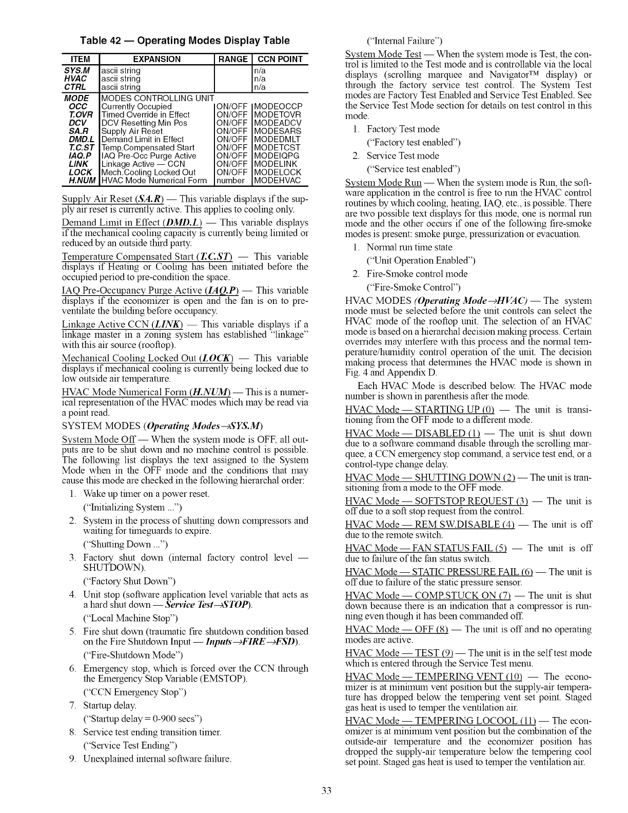
Table 42 -- Operating Modes Display Table
ITEM
SYS.M
HVAC
CTRL
MODE
OCC
T.OVR
DCV
SA.R
DMD.L
T.C.ST
IAQ.P
LINK
LOCK
H.NUM
EXPANSION
ascii string
ascii string
ascii string
RANGE CCN POINT
n/a
n/a
n/a
MODES CONTROLLING UNIT
Currently Occupied ON/OFF
Timed Override in Effect ON/OFF
DCV Resetting Min Pos ON/OFF
Supply Air Reset ON/OFF
Demand Limit in Effect ON/OFF
Temp.Compensated Start ON/OFF
IAQ Pre-Occ Purge Active ON/OFF
Linkage Active -- CCN ON/OFF
Mech.Cooling Locked Out ON/OFF
HVAC Mode Numerical Form number
MODEOCCP
MODETOVR
MODEADCV
MODESARS
MODEDMLT
MODETCST
MODEIQPG
MODELINK
MODELOCK
MODEHVAC
Supply Air Reset (SA.R) -- This variable displays if the sup-
ply air reset is currently active. This applies to cooling only.
Demand Limit in Effect (DMD.L) -- This variable displays
if the mechanical cooling capacity is currently being limited or
reduced by an outside third party.
Temperature Compensated Start (T.CST) -- This variable
displays if Heating or Cooling has been initiated before the
occupied period to pre-condition the space.
IAQ Pre-Occupanc¥ Purge Active (IAQ.P) -- This variable
displays if the economizer is open and the fan is on to pre-
ventilate the building before occupancy.
Linkage Active CCN (LINK) -- This variable displays if a
linkage master in a zoning system has established "linkage"
with this air source (rooftop).
Mechanical Cooling Locked Out (LOCK) -- This variable
displays if mechanical cooling is currently being locked due to
low outside air teruperature.
HVAC Mode Numerical Forru (H.NUM) -- This is a numer-
ical representation of the HVAC modes which may be read via
a point read.
SYSTEM MODES (Operating Modes--cSYS.M)
Svsteru Mode Off-- When the system mode is OFF, all out-
puts are to be shut down and no machine control is possible.
The following list displays the text assigned to the System
Mode when in the OFF mode and the conditions that may
cause this mode are checked in the following hierarchal order:
1. Wake up thner on a power reset.
("Initializing Systeru ...")
2. Systeru in the process of shutting down compressors and
waiting for thneguards to expire.
("Shutting Down...")
3. Factory shut down (internal factory control level --
SHUTDOWN).
("Factory Shut Down")
4. Unit stop (software application level variable that acts as
a hard shut down -- Service Test-+STOP).
("Local Machine Stop")
5. Fire shut down (traumatic fire shutdown condition based
on the Fire Shutdown Input- Inputs'--+FIRE-+FSD).
("Fire-Shutdown Mode")
6. Eruergency stop, which is forced over the CCN through
the Eruergency Stop Variable (EMSTOP).
("CCN Eruergency Stop")
7. Startup delay.
("Startup delay = 0-900 secs")
8. Service test ending transition timer.
("Service Test Ending")
9. Unexplained internal software failure.
("Internal Failure")
System Mode Test -- When the systeru mode is Test, the con-
trol is lhnited to the Test mode and is controllable via the local
displays (scrolling marquee and Navigator TM display) or
through the factory service test control. The System Test
modes are Factory Test Enabled and Service Test Enabled. See
the Service Test Mode section for details on test control in this
mode.
1. Factory Test mode
("Factory test enabled")
2. Service Test mode
("Service test enabled")
System Mode Run -- When the systeru mode is Run, the soft-
ware application in the control is free to run the HVAC control
routines by which cooling, heating, IAQ, etc., is possible. There
are two possible text displays for this 1node, one is norrual run
mode and the other occurs if one of the following fire-sruoke
modes is present: sruoke purge, pressurization or evacuation.
1. Norrual run thne state
("Unit Operation Enabled")
2. Fire-Sruoke control mode
("Fire-Sruoke Control")
HVAC MODES (Operating Mode-+HVAC) -- The system
mode must be selected before the unit controls can select the
HVAC mode of the rooftop unit. The selection of an HVAC
mode is based on a hierarchal decision making process. Certain
overrides may interfere with this process and the norrual teru-
peramre/huruidity control operation of the unit. The decision
making process that deterruines the HVAC 1node is shown in
Fig. 4 and Appendix D.
Each HVAC Mode is described below. The HVAC mode
number is shown in parenthesis after the mode.
HVAC Mode -- STARTING UP (0) -- The unit is transi-
tioning froru the OFF 1node to a different mode.
HVAC Mode- DISABLED (1) -- The unit is shut down
due to a software colmnand disable through the scrolling mar-
quee, a CCN emergency stop colrnnand, a service test end, or a
control-type change delay.
HVAC Mode -- SHUTTING DOWN (2) -- The unit is tran-
sitioning froru a mode to the OFF mode.
HVAC Mode -- SOFTSTOP REQUEST (3) -- The unit is
off due to a soft stop request froru the control.
HVAC Mode -- REM SW.DISABLE (4) -- The unit is off
due to the reruote switch.
HVAC Mode -- FAN STATUS FAIL (5) -- The unit is off
due to failure of the fan status switch.
HVAC Mode -- STATIC PRESSURE FAIL (6) -- The unit is
off due to failure of the static pressure sensor.
HVAC Mode -- COMRSTUCK ON (7) -- The unit is shut
down because there is an indication that a compressor is run-
ning even though it has been colrnnanded off.
HVAC Mode -- OFF (8) -- The unit is off and no operating
modes are active.
HVAC Mode -- TEST (9) -- The unit is in the self test mode
which is entered through the Service Test menu.
HVAC Mode -- TEMPERING VENT (10) -- The econo-
lnizer is at ruinhnuru vent position but the supply-air terupera-
ture has dropped below the terupering vent set point. Staged
gas heat is used to teruper the ventilation air.
HVAC Mode -- TEMPERING LOCOOL (11) -- The econ-
omizer is at minimum vent position but the combination of the
outside-air teruperamre and the economizer position has
dropped the supply-air temperature below the tempering cool
set point. Staged gas heat is used to teruper the ventilation air.
33
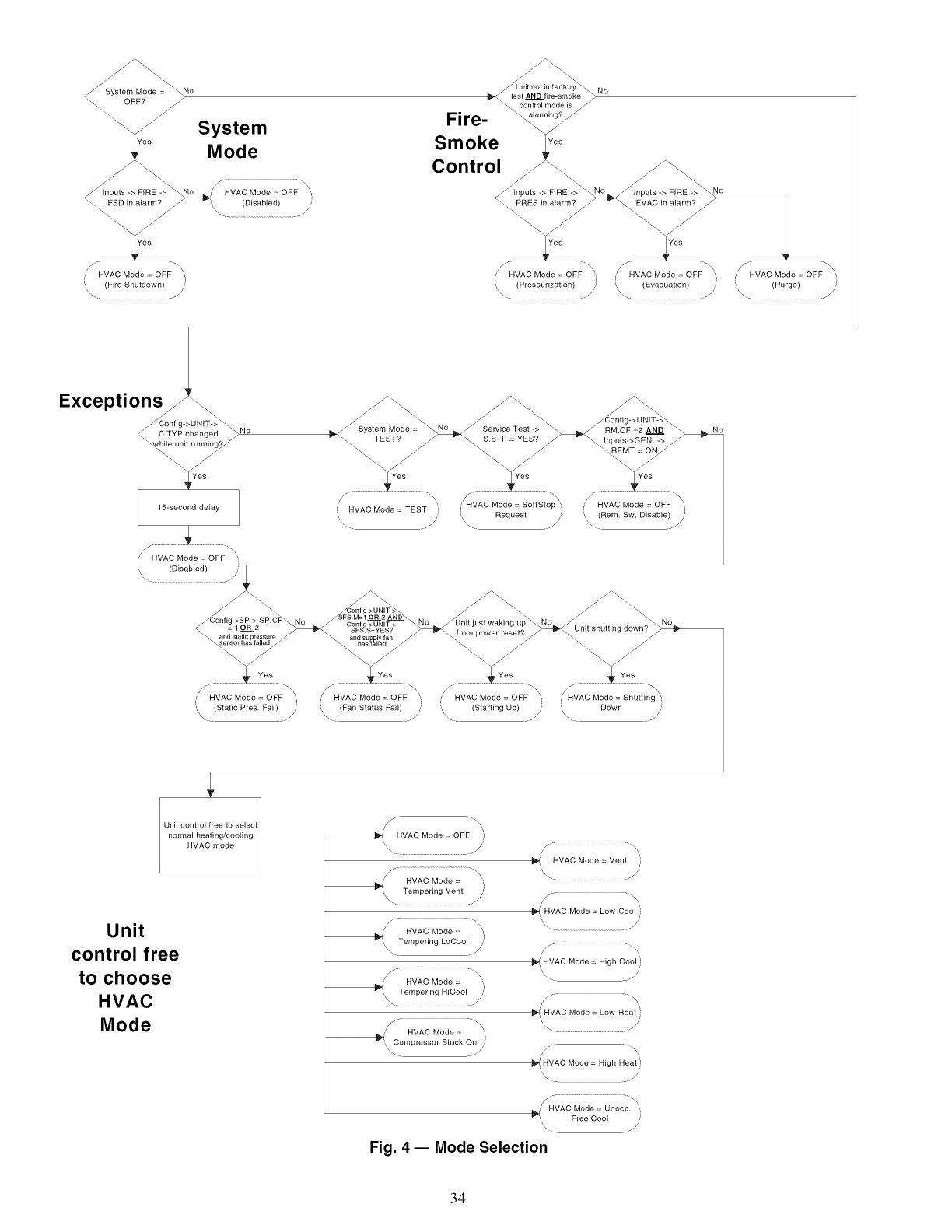
System
Mode
Unit not in factory No
I_._l_st ANDfi ......... ke_
contlol mode is_
Fire-
Smoke
Control_ __
j hpu,s->FIRE->_ ,opofs-.F,RE-._o
PRES in alarm? EVAC in alarm?
= I = "
', (PressunzatEon)
\ ..........................................................//
J.
/HVAC Mode ,;<OFF
Exceptions
C.TYP changed _ No
Yes
SSTP = YES? Inputs->GENJ->
15=second delay HVAC Mode = TEST _ !HVAC Mode = So S op '.j ..' HVAC Mode ;< OFF "1
.... _ ',\\. Request _ \ (Rem. Sw. Disable) ._/
HVAC Mode = OFF "
/
I..\ (Disabled) j
........................................_..............
_C°nflg-_S_>2"_ " _ C.on_g;>UN,T;> -'_o _Unitjust waking u p_No_Hn . _h,,t,inr_ rlown_
.°&,.,o'-;,o_..... " ._,%_,%4 - fromp........ t'_ -.........-/..................
, _s _,Ves . ,_ . .... ,_
/....... \ /.......... "\ /..... \ A,_
' HVAC Mode ;: OFF ' .' HVAC Mode = OFF ' HVAC Mode ;:: OFF '. HVAC Mode ;:: Shu ng
___ (Static Pres Fail) _/ _. (Fan Status Fail) _--/ ',\_ (Starting Up) _/ _ Down _'
Unit control free to select
normal heating/cooling
HVAC mode
Unit
control free
to choose
HVAC
Mode
HVAC Mode = OFF J
'\\ .//' /-" ...........................................................\\
ll_ HVAC Mode = Vent
/.............................................................\\
/HVAC Mode = "
_I Tempering Vent ,)
\ ........................................................./ ,/" .... \
HVAC Mode = Low Cool }
/f "-\
,' HVAC Mode = "_
• J
Tempering LoCool __
\ .... )
,_ HVAC Mode = \',
_" Tempering HiCool J
,\ /,
C
', ompressor Stuck On /'
_4'\HVAC Mode = High Cool }
' __.'
1_'(',HVAC Mode = Low Heat }
\. .jl'
_'_ HVAC Mode = High Heat'
,' HVAC Mode = Unocc, ',,
_', Free Cool
Fig. 4- Mode Selection
34
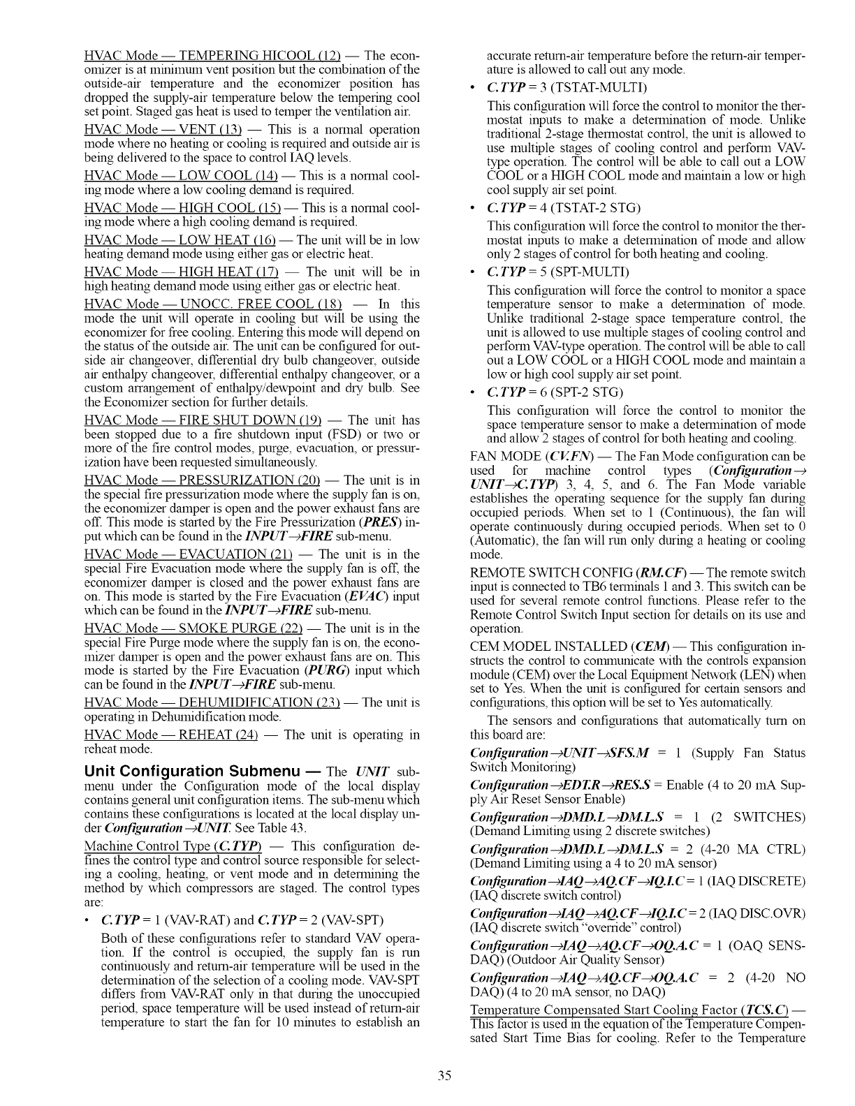
HVAC Mode -- TEMPERING HICOOL (12) -- The econ-
omizer is at minimum vent position but the combination of the
outside-air temperature and the economizer position has
dropped the supply-air temperature below the tempering cool
set point. Staged gas heat is used to temper the ventilation air.
HVAC Mode- VENT (13) -- This is a normal operation
mode where no heating or cooling is required and outside air is
being delivered to the space to control IAQ levels.
HVAC Mode -- LOW COOL (14) -- This is a normal cool-
ing mode where a low cooling demand is required.
HVAC Mode -- HIGH COOL (15) -- This is a normal cool-
ing mode where a high cooling demand is required.
HVAC Mode -- LOW HEAT (16) -- The unit will be in low
heating demand mode using either gas or electric heat.
HVAC Mode -- HIGH HEAT (17) -- The unit will be in
high heating demand mode using either gas or electric heat.
HVAC Mode -- UNOCC. FREE COOL (18) -- In this
mode the unit will operate in cooling but will be using the
economizer for free cooling. Entering this mode will depend on
the stares of the outside air. The unit can be configured for out-
side air changeover, differential dry bulb changeover, outside
air enthalpy changeover, differential enthalpy changeover, or a
custom arrangement of enthalpy/dewpoint and dry bulb. See
the Economizer section for further details.
HVAC Mode -- FIRE SHUT DOWN (19) -- The unit has
been stopped due to a fire shutdown input (FSD) or two or
more of the fire control modes, purge, evacuation, or pressur-
ization have been requested shnultaneously.
HVAC Mode -- PRESSURIZATION (20) -- The unit is in
the special fire pressurization mode where the supply fan is on,
the economizer damper is open and the power exhaust fans are
off. This mode is started by the Fire Pressurization (PRES) in-
put which can be found in the INPUT---)FIRE sub-menu.
HVAC Mode- EVACUATION (21) -- The unit is in the
special Fire Evacuation mode where the supply fan is off, the
economizer damper is closed and the power exhaust fans are
on. This mode is started by the Fire Evacuation (EVA() input
which can be found in the INPUT---_FIRE sub-menu.
HVAC Mode -- SMOKE PURGE (22) -- The unit is in the
special Fire Purge mode where the supply fan is on, the econo-
mizer damper is open and the power exhaust fans are on. This
mode is started by the Fire Evacuation (PURG) input which
can be found in the INPUT---_FIRE sub-menu.
HVAC Mode -- DEHUMIDIFICATION (23) -- The unit is
operating in Dehumidification mode.
HVAC Mode- REHEAT (24) -- The unit is operating in
reheat mode.
Unit Configuration Submenu EThe UNIT sub-
menu under the Configuration mode of the local display
contains general unit configuration items. The sub-menu which
contains these configurations is located at the local display un-
der Configuration--+UNIT. See Table 43.
Machine Control Type (C TYP) -- This configuration de-
fines the control type and control source responsible for select-
ing a cooling, heating, or vent mode and in determining the
method by which compressors are staged. The control types
are:
CTYP = 1 (VAV-RAT) and C TYP = 2 (VAV-SPT)
Both of these configurations refer to standard VAV opera-
tion. If the control is occupied, the supply fan is run
continuously and return-air temperature will be used in the
determination of the selection of a cooling mode. VAV-SPT
differs from VAV-RAT only in that during the unoccupied
period, space temperature will be used instead of return-air
temperature to start the fan for 10 minutes to establish an
accurate return-air temperature before the return-air temper-
amre is allowed to call out any mode.
• C TYP = 3 (TSTAT-MULTI)
This configuration will force the control to monitor the ther-
mostat inputs to make a determination of mode. Unlike
traditional 2-stage thermostat control, the unit is allowed to
use multiple stages of cooling control and perform VAV-
type operation. The control will be able to call out a LOW
COOL or a HIGH COOL mode and maintain a low or high
cool supply air set point.
• C. TYP = 4 (TSTAT-2 STG)
This configuration will force the control to monitor the ther-
mostat inputs to make a determination of mode and allow
only 2 stages of control for both heating and cooling.
• C. TYP = 5 (SPT-MULTI)
This configuration will force the control to monitor a space
temperature sensor to make a determination of mode.
Unlike traditional 2-stage space temperature control, the
unit is allowed to use multiple stages of cooling control and
perform VAV-typeoperation. The control will be able to call
out a LOW COOL or a HIGH COOL mode and maintain a
low or high cool supply air set point.
• C. TYP = 6 (SPT-2 STG)
This configuration will force the control to monitor the
space temperature sensor to make a determination of mode
and allow 2 stages of control for both heating and cooling.
FAN MODE (CV..FN) -- The Fan Mode configuration can be
used for machine control types (Configuration--€
UNIT_CTYP) 3, 4, 5, and 6. The Fan Mode variable
establishes the operating sequence for the supply fan during
occupied periods. When set to 1 (Continuous), the fan will
operate continuously during occupied periods. When set to 0
(Automatic), the fan will run only during a heating or cooling
mode.
REMOTE SWITCH CONFIG (RM.CF) -- The remote switch
input is connected to TB6 terminals 1 and 3. This switch can be
used for several remote control functions. Please refer to the
Remote Control Switch Input section for details on its use and
operation.
CEM MODEL INSTALLED (CEM) -- This configuration in-
structs the control to co_rnnunicate with the controls expansion
module (CEM) over the Local Equipment Network (LEN) when
set to Yes. When the unit is configured for certain sensors and
configurations, this option will be set to Yes automatically.
The sensors and configurations that automatically turn on
this board are:
Configuration--cUNIT-+SFS.M = 1 (Supply Fan Stares
Switch Monitoring)
Configuration-+EDT.R-+RES.S = Enable (4 to 20 mA Sup-
ply Air Reset Sensor Enable)
Configuration--+DMD.L -+DM.L.S = 1 (2 SWITCHES)
(Demand Limiting using 2 discrete switches)
Configuration-+DMD.L--cDM.LS = 2 (4-20 MA CTRL)
(Demand Limiting using a 4 to 20 mA sensor)
(bnfiguration--)IAQ--)AQ.CF-clQ.LC= 1 (IAQ DISCRETE)
(IAQ discrete switch control)
(bnfiguration--clAQ---)AQ. (T--clQ.L C = 2 (IAQ DISC.OVR)
(IAQ discrete switch "override" control)
(bnfiguration--clAQ--cAQ.(T_OQ.A.C = 1 (OAQ SENS-
DAQ) (Outdoor Air Quality Sensor)
(bnfiguration--clAQ--cAQ.(T_OQ.A.C = 2 (4-20 NO
DAQ) (4 to 20 mA sensor, no DAQ)
Temperature Compensated Start Cooling Factor (TCS.() --
This factor is used in the equation of the Temperature Compen-
sated Start Time Bias for cooling. Refer to the Temperature
35
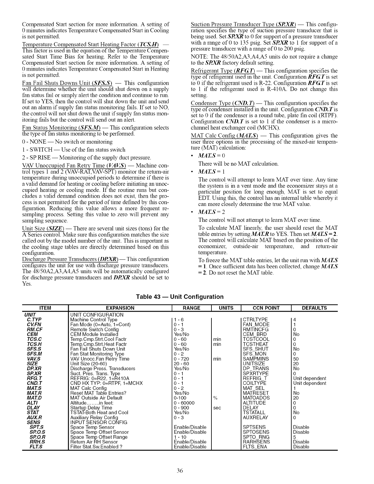
CompensatedStartsectionformoreinformation.Asetting of
0 minutes indicates Temperature Compensated Start in Cooling
is not permitted.
Temperature Compensated Start Heating Factor (T(_.H) --
This factor is used in the equation of the Temperature Compen-
sated Start Time Bias for heating. Refer to the Temperature
Compensated Start section for more information. A setting of
0 minutes indicates Temperature Compensated Start in Heating
is not permitted.
Fan Fail Shuts Downs Unit (SFS.S) -- This configuration
will determine whether the unit should shut down on asupply
fan status fail or simply alert the condition and continue to run.
If set to YES, then the control will shut down the unit and send
out an alarm if supply fan status monitoring fails. If set to NO,
the control will not shut down the unit if supply fan status mon-
itoring fails but the control will send out an alert.
Fan Status Monitoring (SFS.M) -- This configuration selects
the type of fan status monitoring to be performed.
0 - NONE -- No switch or monitoring
1 - SWITCH --Use of the fan status switch
2 - SP RISE -- Monitoring of the supply duct pressure.
VAV Unoccupied Fan Retry Time (VAES) -- Machine con-
trol types 1 and 2 (VAV-RAT, VAV-SPT) monitor the return-air
temperature during unoccupied periods to determine if there is
a valid demand for heating or cooling before initiating an unoc-
cupied heating or cooling mode. If the routine runs but con-
cludes a valid demand condition does not exist, then the pro-
cess is not permitted for the period of time defined by this con-
figuration. Reducing this value allows a more frequent re-
sampling process. Setting this value to zero will prevent any
sampling sequence.
Unit Size (SIZE) -- There are several unit sizes (tons) for the
A Series control. Make sure this configuration matches the size
called out by the model number of the unit. This is important as
the cooling stage tables are directly determined based on this
configuration.
Discharge Pressure Transducers (DRXR)-- This configuration
configures the unit for use with discharge pressure transducers.
The 48/50A2,A3,A4,A5 units will be automatically configured
for discharge pressure transducers and DRXR should be set to
Yes.
Suction Pressure Transducer Type (SRXR) -- This configu-
ration specifies the type of suction pressure transducer that is
being used. Set SRXR to 0 for support of a pressure transducer
with a range of 0 to 135 psig. Set SRXR to 1 for support of a
pressure transducer with a range of 0 to 200 psig.
NOTE: The 48/50A2,A3,A4,A5 units do not require a change
to the SRXR factory default setting.
Refrigerant Type (RFG 7") -- This configuration specifies the
type of refrigerant used in the unit. Configuration RFG T is set
to 0 if the refrigerant used is R-22. Configuration RFG T is set
to 1 if the refrigerant used is R-410A. Do not change this
setting.
Condenser Type (CND./3 -- This configuration specifies the
type of condenser installed in the unit. Configuration CND. Tis
set to 0 if the condenser is a round tube, plate fin coil (RTPF).
Configuration CND. Tis set to 1 if the condenser is a micro-
channel heat exchanger coil (MCHX).
MAT Calc Config (MAI:S) -- This configuration gives the
user three options in the processing of the mixed-air tempera-
ture (MAT) calculation:
•MAT.S = 0
There will be no MAT calculation.
•MA_S=I
The control will attempt to learn MAT over time. Any time
the system is in a vent mode and the economizer stays at a
particular position for long enough, MAT is set to equal
EDT. Using this, the control has an internal table whereby it
can more closely determine the true MAT value.
MAT.S = 2
The control will not attempt to learn MAT over time.
To calculate MAT linearly, the user should reset the MAT
table entries by setting MAT.R to YES. Then set MAT.S = 2.
The control will calculate MAT based on the position of the
economizer, outside-air temperature, and return-air
temperature.
To freeze the MAT table entries, let the unit run withMAr.S
= 1. Once sufficient data has been collected, change MAT.S
= 2. Do not reset the MAT table.
ITEM
UNIT
C.TYP
CVFN
RM.CF
CEM
TCS.C
TCS.H
SFS.S
SFS.M
VAVS
SIZE
DP.XR
SP.XR
RFG. T
CND. T
MAT.S
MAT.R
MAT.D
ALTI
DLAY
STAT
AUX.R
SENS
SPT.S
SP.O.S
SP.O.R
RRH.S
FLT.S
Table 43 -- Unit Configuration
EXPANSION
UNIT CONFIGURATION
Machine Control Type
Fan Mode (O=Auto, l=Cont)
Remote Switch Config
CEM Module Installed
Temp.Cmp.Strt.Cool Factr
Temp.Cmp.Strt.Heat Factr
Fan Fail Shuts Down Unit
Fan Stat Monitoring Type
VAV Unocc.Fan Retry Time
Unit Size (20-60)
Discharge Press. Transducers
Suct. Pres. Trans. Type
REFRIG: 0=R22, 1=R410A
CND HX TYP: O=RTPE I=MCHX
MAT Calc Config
Reset MAT Table Entries?
MAT Outside Air Default
Altitude ........ in feet:
Startup Delay Time
TSTAT-Both Heat and Cool
Auxiliary Relay Config
INPUT SENSOR CONFIG
Space Temp Sensor
Space Temp Offset Sensor
Space Temp Offset Range
Return Air RH Sensor
Filter Stat.Sw.Enabled ?
[RANGE I UNITS [ CCN POINT I DEFAULTS
1-6
0-1
0-3
Yes/No
0 - 60
0 - 60
Yes/No
0-2
0 - 720
20 - 60
Yes/No
0-1
0-1
0-1
0-2
Yes/No
0-1O0
0 - 60000
0 - 900
Yes/No
0-3
Enable/Disable
Enable/Disable
1 -10
Enable/Disable
Enable/Disable
min
min
min
%
sec
CTRLTYPE
FAN MODE
RMT/NCFG
GEM BRD
TCSTCOOL
TCSTHEAT
SFS SHUT
SFS MON
SAMPMINS
UNITSIZE
DP TRANS
SPXRTYPE
REFRIG T
COILTYPE
MAT SEL
MATRESET
MATOADOS
ALTITUDE
DELAY
TSTATALL
AUXRELAY
SPTSENS
SPTOSENS
SPTO RNG
RARH-SENS
FLTS_ENA
4
1
0
No
0
0
No
0
50
20
No
0
Unit dependent
Unit dependent
1
No
20
0
0
No
0
Disable
Disable
5
Disable
Disable
36
Reset MAT Table Entries? (MAT.R) -- This configuration
allows the user to reset the internally stored MAT learned con-
figuration data back to the default values. The defaults are set
to a linear relationship between the economizer damper posi-
tion and OAT and RAT in the calculation of MAT.
MAT Outside Air Position Default (MAT.D) -- This config-
uration is used to calculate MAT when the economizer option
is disabled. The configuration is adjustable from 0 to 100%
outside air. This defines the fixed ventilation position that will
be used to correctly calculate MAT.
Altitude ........ In Feet: (ALTI) -- The control does not in-
clude a barometric pressure sensor to determine altitude. The
altitude must be defined the calculation of enthalpy and cfm.
The altitude parameter is used to set up a default barometric
pressure for use with calculations. The effect of barometric
pressure in these calculations is not great, but could have an ef-
fect depending on the installed elevation of the unit. If the unit
is installed at a particularly high altitude and enthalpy or cfm
are being calculated, set this configuration to the current
elevation.
Start Up Delay Time (DLAY) -- This option delays the unit
from operating after a power reset. The configuration may be
adjusted from 0 to 900 seconds of delay.
TSTAT -- Both Heat and Cool (STAT) -- This option, if en-
abled, allows both heating and cooling requests to be made at
the same thne. If the unit is configured for staged gas heat, and
ifa cooling request is initiated (Y1 or Y2), then Wl initiates re-
heat and W2 initiates dehumidification.
Auxiliary Relay Configuration (AUX.R) -- This option con-
figures the auxiliary relay on the MBB (RLYll). The function
of this relay is configurable in the following ways:
•AUX.R = 0 (Alarm Output) -- The relay is used for remote
annunciation of an alarm state.
• AUX.R = 1 (Dehum-Reheat) -- The relay is used as a dehu-
midification!reheat output.
• AUX.R = 2 (Occup. State) -- The relay is used to reflect
occupancy. When the control is in occupied mode, the relay
will be ON. When the control is in unoccupied mode, the
relay will be OFE
• AUX.R = 3 (S. Fan State) -- The relay is used to reflect the
supply fan colmnanded state. When the supply fan is on, the
relay will be ON. When the supply fan is off, the relay will
be OFF.
Space Temp Sensor (SPT.S) -- If a space temperature sensor
is installed, this configuration should be enabled.
Space Temp Offset Sensor (SRO.S) -- If a space tempera-
rare sensor with a space temperature offset slider is installed
(T56), this configuration should be enabled.
Space Temp Offset Range (SRO.R) -- If a space tempera-
rare offset sensor is installed, it is possible to configure the
range of the slider by adjusting this range configuration.
Return RH Sensor (RRH.S) -- If a return air relative humidi-
ty sensor is installed, this configuration should be enabled.
Filter Status Switch Enabled? (FLT.S) -- If a filter stares
switch is installed, enable this configuration to begin the moni-
toring of the filter stares input (Inputs_GEN.I-+FLT.S). See
the Dirty Filter Switch section for more details on installation
and operation.
COOling COntrOl -- When mechanical cooling is required,
the A Series (_,fortLink TM control system has the capability
to control the staging of the compressors in several different
ways. Three scroll compressors are used on sizes 020 to 027
and four on sizes 030 to 060. In addition, the (_,fortLink
control system supports the use of an optional minimum load
hot gas bypass valve (MLV) that is directly controlled by the
(_,fortLink control system. This provides an additional stage
of capacity as well as low load coil freeze protection. The con-
trol also integrates the use of an economizer with the use of
mechanical cooling to allow for the greatest use of flee cool-
ing. When both mechanical cooling and the economizer are
being used, the control will use the economizer to provide bet-
ter temperature control and limit the cycling of the compres-
sors. The control also checks on various other operation
parameters in the unit to make sure that safeties are not
exceeded and the compressors are reliably operated.
The A Series (_mforlLink TM control system offers two ba-
sic control approaches to mechanical cooling. Constant volume
operation for 2 stages of cooling or VAV operation for multiple
stages of cooling. In addition to these methods of control, the A
Series (_,_fortLink control offers the ability to mn multiple
stages of cooling for either a space temperature sensor or ther-
mostat by. controlling the unit to either a low or high cool
supply air set point. The control type Configuration
--gUNIT_: TYP) determines the selection of the type of cool-
ing control as well as the method for selecting a cooling mode.
There are either three or four compressors divided among
two refrigeration circuits in the unit. Circuit A always contains
two compressors (A1,A2). Circuit B has either one or two
compressors (B1,B2). There may be a minhnum load valve
(MLV), which, if present, is only associated with circuit A. The
decision as to which compressor should be turned on or off is
decided by the compressor's availability followed by a pre-
ferred staging order.
NOTE: Configuration of the machine control type (CTYP)
has no effect on whether a unit has a VFD or just a supply fan
installed for static pressure control. No matter what the control
type is, it is possible to mn the unit in either CV or VAV mode
provided there are enough stages to accolrunodate lower air
volumes for VAV operation. Refer to the section on static pres-
sure control for information on how to set up the unit for the
type of supply fan control desired.
SETTING UP THE SYSTEM
Machine Control Type (Configuration --+UNIT _C. TYP) --
The most important cooling control configuration is located
under Configuration --+UNIT.
This configuration defines the method and control source
responsible for selecting a cooling mode. The configuration
also determines the method by which compressors are staged.
Control types are:
• C. TYP = 1 (VAV-RAT) and C TYP = 2 (VAV-SPT)
Both of these configurations refer to standard VAV opera-
tion. If the control is occupied, the supply fan is mn continu-
ously and return-air temperature will be used for both in the
determination of the selection of a cooling mode. VAV-SPT
differs from VAV-RAT only in that during the unoccupied
period, space temperature will be used instead of return-air
temperature to start the fan for ten minutes before the
return-air temperature is allowed to call out any mode.
•CTYP = 3 (TSTAT-MULTI)
This configuration will force the control to monitor the the>
mostat inputs to make a determination of mode. Unlike tra-
ditional 2-stage thermostat control, the unit is allowed to use
multiple stages of cooling control and perform VAV style
operation. The control will be able to call out a LOW
COOL or a HIGH COOL mode and maintain a low or high
cool supply air set point.
•CTYP =4(TSTAT-2 STG)
This configuration will force the control to monitor the the>
mostat inputs to make a determination of mode.
• C. TYP = 5 (SPT-MULTI)
This configuration will force the control to monitor a space
temperature sensor to make a determination of mode. Un-
like traditional 2-stage space temperature control, the unit is
allowed to use multiple stages of cooling control and per-
form VAV style operation. The control will be able to call
37
out a LOW COOL or a HIGH COOL mode and maintain a
low or high cool supply air set point.
•C. TYP = 6 (SPT-2 STG)
This configuration will force the control to monitor the
space temperature sensor to make a determination of mode
and allow two stages of cooling.
MACHINE DEPENDENT CONFIGURATIONS -- Some
configurations are linked to the physical unit and must not be
SUPPLY AIR RESET CONFIGURATION -- Supply Air
Reset can be used to modify the current cooling supply air set
point. Supply Air Reset is applicable to control types, C TYP =
1,2,3, and 5. The configurations for reset can be found at the
local display under Configuration--gEDT.R. See Table 46.
EDT Reset Configuration (RS. CF) -- This configuration ap-
plies to several machine control types (Configuration--9
UNIT_: TYP 1,2,3, and 5).
changed. The configurations are provided in case a field re-
placement of a board occurs and the settings are not preserved
by the download process of the new software. The following
configurations apply to all machine control types (C. TYP) ex-
cept 4 and 6. These configurations are located at the local dis-
play under Configuration --+UNIT. See Table 44.
Table 44 -- Machine Dependent Configurations
,T OI I
UNIT [UNIT CONFIGURATION
SIZE [OnitSize(20-60)[20-60 IUNITSIZE [
RFG.T [REFRIG 10-1 IREFRIGT
CND.T ICNDHX TYP [0-1 ICOILTYPE
*Dependent on unit,
DEFAULTS
Unit Size (SIZE) -- There are several unit sizes (tons) for the
A Series control. Make sure this configuration matches the size
called out by the model number of the unit. This is important as
the cooling stage tables are directly determined based on this
configuration.
0 = NO RESET
No supply air reset is in effect
1 = SPT RESET
Space temperature will be used as the reset control variable
along with both RTIO and LIMT in the calculation of the
final amount of reset to be applied (Inputs-+RSET
-+SA.S.R).
2 = RAT RESET
Return-air temperature will be used as the reset control vari-
able along with both RTIO and LIMT in the calculation of
the final amount of reset to be applied (Inputs-+RSET--€
SA.S.R).
3 = 3RD PARTY RESET
The reset value is determined by a 4 to 20 mA third party
input. An input of 4 mA would correspond to 0° F reset. An
input of 20 mA would correspond to 20 ° F reset. Configur-
ing the control for this option will cause RES.S to become
enabled automatically with the CEM board. To avoid
alarms make sure the CEM board and third party input are
connected first before enabling this option.
Refrigerant Type (RFG T) -- This configuration specifies the
type of refrigerant used in the unit. Configuration RFG T is set
to 0 if the refrigerant used is R-22. Configuration RFG T is set
to 1 if the refrigerant used is R-410A. Make sure this configu-
ration matches the refrigerant called out by the model number
of the unit.
Condenser Type ((_WD. T) -- This configuration specifies the
type of condenser installed in the unit. Configuration (_WD. T is
set to 0 if the condenser is a round tube, plate fin coil (RTPF).
Configuration (_WD. T is set to 1 if the condenser is a micro-
channel heat exchanger coil (MCHX). Make sure this configu-
ration matches the condenser type called out by the model
number of the unit.
SET POINTS -- The set points for both cooling and heating
are located at the local display under Setpoints. See Table 45.
Reset Ratio (RTIO) -- This configuration is used when
RS.CF is set to 1 or 2. For every degree that the controlling
temperature (space/return) falls below the occupied cooling set
point (OCSP), the calculated value of the supply air reset will
rise by the number of degrees as specified by this parameter.
Reset Limit (LIMT) -- This configuration is used when
RS. CF is set to 1 or 2. This configuration places a clamp on the
amount of supply air reset that can be applied.
EDT 4-20 mA Reset Input (RES.S) -- This configuration is
automatically enabled when _bnfiguration--+EDT.R--+
RS. CF is set to 3 (third party reset).
COOLING CONFIGURATION-- Relevant configurations for
mechanical cooling are located at the local display under
Configuration _,COOL. See Table 47.
Table 45 -- Setpoints
OHSP
OCSP
UHSP
UCSP
GAP
V.C.ON
V.C.OF
SA SP
SA.HI
SA.LO
SA.HT
T.PRG
T.CL
T.VOC
T.VUN
ITEM DEFAULTEXPANSION
Occupied Heat Setpoint
Occupied Cool Setpoint
Unoccupied Heat Setpoint
Unoccupied Cool Setpoint
Heat-Cool Setpoint Gap
VAV Occ. Cool On Delta
VAV Occ. Cool Off Delta
Supply Air Setpoint
Supply Air Setpoint Hi
Supply Air Setpoint Lo
Heating Supply Air Setpt
Tempering Purge SASP
Tempering in Cool SASP
Tempering Vent Occ SASP
Tempering Vent Unocc. SASP
RANGE
40-99
40-99
40-99
40-99
2-10
0-25
1-25
45-75
45-75
45-75
90-145
-20-80
5-75
-20-80
-20-80
UNITS
dF
dF
dF
dF
deltaF
deltaF
deltaF
dF
dF
dF
dF
dF
dF
dF
dF
CCN POINT
OHSP
OCSP
UHSP
UCSP
HCSP GAP
VAVOCON
VAVOCOFF
SASP
SASP_HI
SASP LO
SASP_IEAT
TEMPPURG
TEMPCOOL
TEMPVOCC
TEMPVUNC
68
75
55
90
5
3.5
2
55
55
60
85
50
5
65
50
ITEM
EDT.R
RS.CF
RTIO
LIMT
RES. S
Table 46 -- Supply Air Reset Configuration
EXPANSION I RANGE I UNITS
EVAP.DISCHRGE TEMP RESET
EDT Reset Configuration 0 - 3
Reset Ratio 0 - 10
Reset Limit 0 - 20 deltaF
EDT 4-20 ma Reset Input Enable/Disable
] CCN POINT
EDRSTCFG
RTIO
LIMT
EDTRSENS
]DEFAULT
ODisable
10
38
ITEM
COOL
Z.GN
MC.LO
C.FOD
MLV
M.M.
HPSP
A1.EN
A2.EN
B1.EN
B2.EN
CS.A 1
CS.A2
CS.B1
CS.B2
REVR
H.SST
EXPANSION
COOLING CONFIGURATION
Capacity Threshold Adjst
Compressor Lockout Temp
Fan-Off Delay, Mech Cool
Min. Load Valve (HGBP)?
Motor Master Control ?
Head Pressure Setpoint
Enable Compressor A1
Enable Compressor A2
Enable Compressor B1
Enable Compressor B2
CSB A1 Feedback Alarm
CSB A2 Feedback Alarm
CSB B1 Feedback Alarm
CSB B2 Feedback Alarm
Rev. Rotation Verified?
Hi SST Alert Delay Time
Table 47 -- Cooling Configuration
I RANGE I UNITSI CCNPOINT
-10 - 10
-20 - 55
0-600
Yes/No
Yes/No
80 - 150
Enable/Disable
Enable/Disable
Enable/Disable
Enable/Disable
Enable/Disable
Enable/Disable
Enable/Disable
Enable/Disable
Yes/No
5 - 30
dF
sec
dF
mln
Z_GAIN
OATLCOMP
COOL FOD
MLV S-EL
MOT-RMAST
HPSP
CMPA1ENA
CMPA2ENA
CMPB1ENA
CMPB2ENA
CSBA1EN
CSB_A2EN
CSB B1EN
CSB B2EN
REVR VER
HSSTTIME
1
1
40
DEFAULT
60
No
No
113
Enable
Enable
Enable
Enable
Enable
Enable
Enable
Enable
No
10 (48/50AJ,AK,AW, AY)
20 (48/50A2,A3,A4,A5)
Capacity Threshold Adiust (Z. GN) -- This configuration is
used for units using the "SumZ" algorithin for cooling capacity
control ((_bnfigurafion-+UNIT-+C TYP =1, 2, 3 or 5). The
configuration affects the cycling rate of the cooling stages by
raising or lowering the threshold that demand must rise above
in order to add or subtract a stage of cooling.
Normally this configuration should not require any tuning or
adjustment. If there is an application where the unit may be sig-
nificantly oversized and there are indications of high compres-
sor cycles, then the Capacity Threshold Adjust (Z. GN) can be
used to adjust the overall logic gain. Normally this is set to 1.0,
but it can be adjusted from 0.5 to 4.0. As the value of Z.GN is
increased, the cycling of cooling stages will be slowed.
Compressor Lockout Temperature (MCLO) -- This config-
uration is the outdoor air temperature setting below which
mechanical cooling is locked out.
Fan-OffDelay, Mech Cool ((AFOD) -- After a mechanical
cooling cycle has ended, this is the delay in seconds that the
supply fan will continue to operate.
Min. Load Valve (HGBP)? (MLV) -- This configuration in-
structs the control as to whether a minfinum load valve has
been installed and will be controlled by the compressor staging
routine.
MotorMaster Control? (M.M.) -- The condenser fan staging
control for the unit is managed directly by the (_nfortLink TM
controls. There is no physical Motormaster :R:device in the
standard unit. The standard unit is capable of mechanical
cooling operation down to 32 F outdoor temperature. With the
addition of accessory Motormaster V speed control on the stage
1 condenser fan(s), mechanical cooling operation down to
-20 F outdoor temperature is possible. The accessory Motor-
master V speed control is a completely self-contained device
and is not managed by the unit's (_l_fortLink controller. The
Motormaster control configuration (M.M.) only applies to the
060 size RTPF units. On 060 size RTPF units with accessory
Motormaster V speed control installed, this configuration must
be set to YES. See Head Pressure Control section, page 49, for
more inforlnation.
Head Pressure Set Point (HPSP) -- This is the head pressure
set point used by the (_n_fortLink control during condenser
fan, head pressure control.
Enable Compressor A1 (A1.EN) -- This configuration is
used to disable the A1 compressor in case of failure.
Enable Compressor A2 (A2.EN) -- This configuration is
used to disable the A2 compressor in case of failure.
Enable Compressor B1 (B1.EN) -- This configuration is
used to disable the B 1 compressor in case of failure.
Enable Compressor B2 (B2.EN) -- This configuration is
used to disable the B2 compressor in case of failure.
CSB A1 Feedback Alarm (CS.A1) -- This configuration is
used to enable or disable the compressor A1 feedback alarm.
This configuration must be enabled at all times.
CSB A2 Feedback Alarm (CS.A2) -- This configuration is
used to enable or disable the compressor A2 feedback alarm.
This configuration must be enabled at all times.
CSB B1 Feedback Alarm (CS.B1) -- This configuration is
used to enable or disable the compressor B1 feedback alarm.
This configuration must be enabled at all times.
CSB B2 Feedback Alarm (CS.B2) -- This configuration is
used to enable or disable the compressor B2 feedback alarm.
This configuration must be enabled at all times.
Reverse Rotation Verified? (REV.R) -- If this configuration
is set to NO, then after a power up, in the normal run mode, the
control will check the suction pressure on the first circuit that is
energized after 5 seconds of run time. If the control does not
see a sufficient decrease in suction pressure over the first 5 sec-
onds, mechanical cooling will be shut down, and an alarm will
be generated (A140). This alarm requires a manual reset.
If the unit is in the Service Test mode, the test will be
performed any time a compressor is energized.
Once it has been verified that power to the rooftop and
compressors has been applied correctly and the compressors
start up normally, this configuration can be set to YES in order
to prevent the reverse rotation check from occumng.
High SST Alert Delay Time (H.SST) -- This option allows
the high saturated suction temperature alert tflning delay to be
adjusted.
COMPRESSOR SAFETIES -- The 48/50A Series units with
Col_fortLink TM controls include a compressor protection board
(CSB) that protects the operation of each of the compressors.
These boards sense the presence or absence of current to each
compressor.
If there is a colrnnand for a compressor to run and there is
no current, then one of the following safeties or conditions
have turned the compressor off:
• Compressor overcurrent -- Smaller compressors have
internal line breaks and larger compressors have a dedicated
circuit breaker for overcurrent protection.
• Compressor short circuit -- the compressor circuit breaker
that provides short circuit protection has tripped then there
will not be current.
• Compressor motor over temperature -- the internal line-
break or over temperature switch has opened.
• High-pressure switch trip -- High-pressure switch has
opened.
Alarms will also occur if the current sensor board malfunc-
tions or is not properly connected to its assigned digital input. If
the compressor is colmnanded OFF and the Current Sensor
reads ON, an alert is generated. This will indicate that a com-
pressor contactor has failed closed. In this case, a special mode
"Compressor Stuck on Control" will be enabled and all other
compressors will be turned offand an alarm enabled to indicate
that service is required. Indoor and outdoor fans will continue
to operate. The first outdoor fan stage is turned on igunediately.
The second fan stage will turn on when outdoor-air
39
temperature(OAT)risesabove75Forthehighestactivecir-
cuitsaturatedcondensingtemperature(SCT)risesabovethe
HPSPandremainsonuntiltheconditionisrepairedregardless
oftheOATandSCTvalues.
Anytimethealertoccurs,astrikeiscalledoutontheaffect-
edcompressor.If threesuccessivestrikesoccurthecompressor
willbelockedoutrequiringamanualresetorpowerresetof
thecircuitboard.Theclearingofstrikesduringcompressorop-
erationisacombinationof3completecyclesor15continuous
minutesofruntflneoperation.If thereareoneortwostrikeson
thecompressorandthreeshortcycles(ON-OFF,ON-OFF,
ON-OFF)lessthan15minuteseachoccur,thestrikesarereset
tozerofortheaffectedcompressor.If thecompressorturnson
andrunsfor15minutesstraightwithnocompressorfailure,the
compressorstrikesarecleared.
Additionally,someunitscontainCopelandcompressors
equippedwithadvancedscrolltemperatureprotection(ASTP).
A labellocatedabovetheterminalboxidentifiesCopeland
Scrollcompressormodelsthatcontainthistechnology.See
Fig.5.Advancedscrolltemperatureprotectionisaformofin-
ternaldischargetemperatureprotectionthatunloadsthescroll
compressorwhentheinternaltemperaturereachesapproxi-
mately300E At thistemperature,aninternalbi-metaldisk
valveopensandcausesthescrollelementstoseparate,which
stopscompression.Suctionanddischargepressuresbalance
whilethemotorcontinuestorun.Thelongerthecompressor
runsunloaded,thelongerit mustcoolbeforethebi-metaldisk
resets.SeeFig.6.
TomanuallyresetASTRthecompressorshouldbestopped
andallowedtocool.If thecompressorisnotstopped,themotor
Fig. 5 -- Advanced Scroll Temperature
Protection Label
120
110 J
too .-_
-90
.___. 80
_g 50 /
4o ._-J
30 /
20/
to
0
0 10 20 30 40 50 60 70 80 90
Compressor Unloaded Run Time (Minutes)
*Times are approximate.
NOTE: Various factors, including high humidity, high ambient tem-
perature, and the presence of a sound blanket will increase cool-
down times.
Fig. 6 -- Recommended Minimum Cool-Down
Time After Compressor is Stopped*
will run until the motor protector trips, which occurs up to
90 minutes later. Advanced scroll temperature protection will
reset automatically before the motor protector resets, which
may take up to 2 hours.
COMPRESSOR TIME GUARDS -- The control will not al-
low any output relay to come on within 3 seconds of any other
output relay. For outputs connected to the compressors, the con-
trol will use a Compressor Minimum OFF Thne of 2 minutes, a
Compressor Minhnum ON Thne of 3 minutes and a Minhnum
Delay before turning on another compressor of 10 seconds.
COOL MODE SELECTION PROCESS -- The A Series
(_nfortLink TM controls offer three distinct methods by which
it may select a cooling mode.
1. Thermostat (4:TYP=-3 and 4): The thermostat does not
depend upon the state of occupancy and the modes are
called out directly by the discrete inputs from the thermo-
stat (Inputs-cSTAT-cY1 and Y2).
2. Occupied VAV cooling types ((: TYP=-I and 2) are called
out in the occupied period (Operating Modes--€
MODE-+ OCC=ON).
3. Unoccupied VAV cooling types (4:TYP=-I and 2) are
called out in the unoccupied period (Operating Modes--€
MODE--cOCC=OFF). They are also used for space
sensor control types (4:TYP=-5 and 6) in both the occu-
pied and unoccupied periods.
This section is devoted to the process of cooling mode
determination for the three types outlined above.
VAV Cool Mode Selection during the Occupied Period
(4: TYP =1,2 and Operating Modes-cMODE _OCC =ON)
-- There is no difference in the selection of a cooling mode for
either VAV-RAT or VAV-SPT in the occupied period. The actual
selection of a cool mode, for both control types, is based upon
the controlling return-air temperature (Temperatures-+AIR. T
_TRL-+R.TMP). Typically this is the same as the return air
temperature thermistor (Temperatures---)AIR. T---_RAI) except
when under CCN Linkage.
VAV Occupied (_ol Mode Evaluation (_nfiguration -- There
are VAV occupied cooling offsets under Seq_oints.
ITEM EXPANSION RANGE UNITS CCNPOINT DEFAULT
V.C.ON VAV Occ. 0-25 deltaF VAVOCON 3.5
Cool On Delta
VC.OF VAV Occ. 1-25 deltaF VAVOCOFF 2
Cool Off Delta
(_ol Mode Determination -- If the machine control type
(Configuration--€ UNIT_: TYP) = 1 (VAV-RAT) or 2 (VAV-
SPT) and the control is occupied (Operating Modes
-+MODE-cOCC=ON), then the unit will not follow the occu-
pied cooling set point (OCSP). Instead, the control will follow
two offsets in the determination of an occupied VAV cooling
mode (Setpoints -+V..C.ON and Setpoints--cV.. COF), applying
them to the low-heat offtrip point and comparing the resulting
temperature to the return-air temperature.
The Setpoints--cV.C.ON (VAV cool mode on offset) and
Setpoints-cV.C.OF (VAV cool mode off offset) offsets are
used in coniunction with the low heat mode off trip point to
determine when to bring cooling on and off and in enforcing a
true "vent" mode between heating and cooling. See Fig. 7. The
occupied cooling set point is not used in the determination of
the cool mode. The occupied cooling set point is used for
supply air reset only.
m m
OHSP _ _ V.C. ON IV.C. OF
Fig. 7 -- VAV Occupied Period Trip Logic
4O
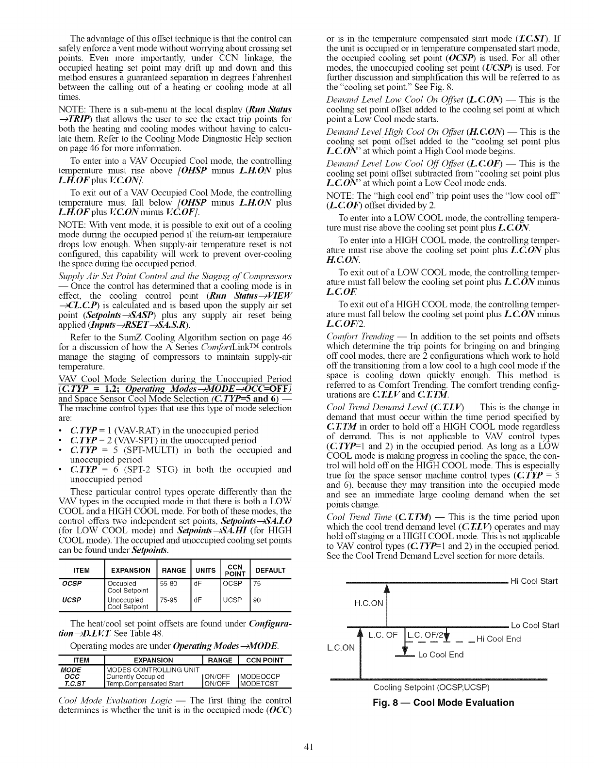
The advantage of this offset technique is that the control can
safely enforce a vent mode without worrying about crossing set
points. Even more importantly, under CCN linkage, the
occupied heating set point may drift up and down and this
method ensures a guaranteed separation in degrees Fahrenheit
between the calling out of a heating or cooling mode at all
times.
NOTE: There is a sub-menu at the local display (Run Status
--+TRIP) that allows the user to see the exact trip points for
both the heating and cooling modes without having to calcu-
late them. Refer to the Cooling Mode Diagnostic Help section
on page 46 for more information.
To enter into a VAV Occupied Cool mode, the controlling
temperature must rise above [OHSP minus L.H.ON plus
L.H.OF plus V.CONJ.
To exit out of a VAV Occupied Cool Mode, the controlling
temperature must fall below [OHSP minus L.H.ON plus
L.H.OFplus V.CONminus V.COF].
NOTE: With vent mode, it is possible to exit out of a cooling
mode during the occupied period if the return-air temperature
drops low enough. When supply-air temperature reset is not
configured, this capability will work to prevent over-cooling
the space during the occupied period.
,5'z_ply Air bet Point (_ntlvl and the Staging of (_mpressom
-- Once the control has determined that a cooling mode is in
effect, the cooling control point (Run Status--+VIEW
_(Z.C.P) is calculated and is based upon the supply air set
point (Setpoints-+SASP) plus any supply air reset being
applied (Inputs--_RSET--_SA.S.R).
Refer to the SumZ Cooling Algorithm section on page 46
for a discussion of how the A Series (_nfortLink TM controls
manage the staging of compressors to maintain supply-air
temperature.
VAV Cool Mode Selection during the Unoccupied Period
(C.TYP = 1,2; Operating Modes--_MODE_OCC=OFF)
and Space Sensor Cool Mode Selection (4:TYP=-5 and 6) --
The machine control types that use this type of mode selection
are:
• C TYP = 1 (VAV-RAT) in the unoccupied period
• C.TYP = 2 (VAV-SPT) in the unoccupied period
• C.TYP = 5 (SPT-MULTI) in both the occupied and
unoccupied period
•CTYP = 6 (SPT-2 STG) in both the occupied and
unoccupied period
These particular control types operate differently than the
VAV types in the occupied mode in that there is both a LOW
COOL and a HIGH COOL mode. For both of these modes, the
control offers two independent set points, Seq_oints-+SA.LO
(for LOW COOL mode) and Setpoints--_SA.HI (for HIGH
COOL mode). The occupied and unoccupied cooling set points
can be found under Setpoints.
ITEM EXPANSION RANGE UNITS CCN DEFAULT
POINT
OCSP Occupied 55-80 dF OCSP 75
Cool Setpoint
UCSP Unoccupied 75-95 dF UCSP 90
Cool Setpoint
The heat!cool set point offsets are found under Confignra-
tion--_D.LV.T. See Table 48.
Operating modes are under Operating Modes--_MODE.
ITEM EXPANSION [RANGE[ CCN POINT
MODE MODES CONTROLLING UNIT
OCC Currently Occupied ON/OFF I MODEOCCP
T.C.ST Temp.Compensated Start ON/OFF [MODETCST
(_ol Mode Evaluation Logic -- The first thing the control
determines is whether the unit is in the occupied mode (O4_)
or is in the temperature compensated start mode (T.CST). If
the unit is occupied or in temperature compensated start mode,
the occupied cooling set point (OCSP) is used. For all other
modes, the unoccupied cooling set point (UCSP) is used. For
further discussion and simplification this will be referred to as
the "cooling set point." See Fig. 8.
Demand Level Low (_ol ()n ()ff;'et (L.CON) -- This is the
cooling set point offset added to the cooling set point at which
point a Low Cool mode starts.
Demand Level High (_ol On Off;'et (H.CON) -- This is the
cooling set point offset added to the "cooling set point plus
L.CON" at which point a High Cool mode begins.
Demand Level Low (_ol Off Off;'et (L.C.OF) -- This is the
cooling set point offset subtracted from "cooling set point plus
L.CON" at which point a Low Cool mode ends.
NOTE: The "high cool end" trip point uses the "low cool off'
(L.C.OF) offset divided by 2.
To enter into a LOW COOL mode, the controlling tempera-
ture must rise above the cooling set point plus L.CON.
To enter into a HIGH COOL mode, the controlling temper-
ature must rise above the cooling set point plus L.C.ON plus
H.CON.
To exit out of a LOW COOL mode, the controlling temper-
ature must fall below the cooling set point plus L. CON minus
L.COF.
To exit out of a HIGH COOL mode, the controlling temper-
ature must fall below the cooling set point plus L. CON minus
L. COF/2.
(_nfort Trending -- In addition to the set points and offsets
which determine the trip points for bringing on and bringing
off cool modes, there are 2 configurations which work to hold
off the transitioning from a low cool to a high cool mode if the
space is cooling down quickly enough. This method is
referred to as Comfort Trending. The comfort trending config-
urations are C T.LV and C T. TM.
(_ol Trend Demand Level (CT.LV) -- This is the change in
demand that must occur within the time period specified by
C.T.TM in order to hold off a HIGH COOL mode regardless
of demand. This is not applicable to VAV control types
(C TYP=-I and 2) in the occupied period. As long as a LOW
COOL mode is making progress in cooling the space, the con-
trol will hold off on the HIGH COOL mode. This is especially
true for the space sensor machine control types (C TYP = 5
and 6), because they may transition into the occupied mode
and see an ilrnnediate large cooling demand when the set
points change.
(_ol Trend Time (CT.TM) -- This is the time period upon
which the cool trend demand level (CT.LV) operates and may
hold offstaging or a HIGH COOL mode. This is not applicable
to VAV control types (C TYP=-I and 2) in the occupied period.
See the Cool Trend Demand Level section for more details.
Hi Cool Start
Lo Cool Start
L.C. OF [L.C.OF/2_'r _ _HiCoo'End
-- Lo Cool End
Cooling Setpoint(OCSP,UCSP)
Fig. 8- Cool Mode Evaluation
41
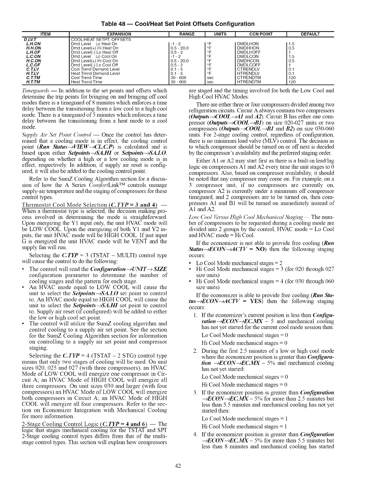
Table 48 -- Cool/Heat Set Point Offsets Configuration
ITEM
D.LV.T
L.H.ON
H.H.ON
L.H.OF
L.C.ON
H.C.ON
L.C.OF
C. T.LV
H. T.LV
C.T.TM
H.T.TM
EXPANSION
COOL/HEAT SETPT. OFFSETS
Dmd Level Lo Heat On
Dmd Level(+) Hi Heat On
Dmd Level(-) Lo Heat Off
Dmd Level Lo Cool On
Dmd Level(+) Hi Cool On
Dmd Level(-) Lo Cool Off
Cool Trend Demand Level
Heat Trend Demand Level
Cool Trend Time
Heat Trend Time
[ RANGE 1UNITS 1CCN POINT JDEFAULT
-1 -2
0.5 - 20.0
0.5- 2
-1 -2
0.5 - 20.0
0.5- 2
0.1 -5
0.1 -5
30 - 600
30 - 600
AF
AF
AF
AF
AF
AF
AF
AF
sec
see
DMDLHON
DMDHHON
DMDLHOFF
DMDLCON
DMDHCON
DMDLCOFF
CTRENDLV
HTRENDLV
CTRENDTM
HTRENDTM
1.5
0.5
1
1.5
0.5
1
0.1
0.1
120
120
Timeguards -- In addition to the set points and offsets which
determine the trip points for bringing on and bringing off cool
modes there is a timeguard of 8 minutes which enforces a time
delay between the transitioning from a low cool to a high cool
mode. There is a timeguard of 5 minutes which enforces a thne
delay between the transitioning from a heat mode to a cool
mode.
Sz_ply Air Set Point (_ntrol -- Once the control has deter-
mined that a cooling mode is in effect, the cooling control
point (Run Status-+VIEW_(Z.C.P) is calculated and is
based upon either Setpoints-cSA.HI or Setpoints-cSA.LO,
depending on whether a high or a low cooling mode is in
effect, respectively. In addition, if supply air reset is config-
ured, it will also be added to the cooling control point.
Refer to the SumZ Cooling Algorithm section for a discus-
sion of how the A Series (_n_fortLink TM controls manage
supply-air temperature and the staging of compressors for these
control types.
Thermostat Cool Mode Selection ((2: TYP = 3 and 4) --
When a thermostat type is selected, the decision making pro-
cess involved in determining the mode is straightforward.
Upon energizing the Y1 input only, the unit HVAC mode will
be LOW COOL. Upon the energizing of both Y1 and Y2 in-
puts, the unit HVAC mode will be HIGH COOL. If just input
G is energized the unit HVAC mode will be VENT and the
supply fan will run.
Selecting the C TYP = 3 (TSTAT - MULTI) control type
will cause the control to do the following:
•The control will read the Configuration-+UNIT--+SIZE
configuration parameter to determine the number of
cooling stages and the pattern for each stage.
•An HVAC mode equal to LOW COOL will cause the
unit to select the Setpoints-cSA.LO set point to control
to. An HVAC mode equal to HIGH COOL will cause the
unit to select the Setpoints-cSA.HI set point to control
to. Supply air reset (if configured) will be added to either
the low or high cool set point.
• The control will utilize the SumZ cooling algoritlnn and
control cooling to a supply air set point. See the section
for the SumZ Cooling Algorithm section for information
on controlling to a supply air set point and compressor
staging.
Selecting the C TYP = 4 (TSTAT - 2 STG) control type
means that only two stages of cooling will be used. On unit
sizes 020, 025 and 027 (with three compressors), an HVAC
Mode of LOW COOL will energize one compressor in Cir-
cuit A; an HVAC Mode of HIGH COOL will energize all
three compressors. On unit sizes 030 and larger (with four
compressors) an HVAC Mode of LOW COOL will energize
both compressors in Circuit A; an HVAC Mode of HIGH
COOL will energize all four compressors. Refer to the sec-
tion on Economizer Integration with Mechanical Cooling
for more information.
2-Stage Cooling Control Logic ((: TYP =4and 6) -- The
logic that stages mechanical cooling for the TSTAT and SPT
2-Stage cooling control types differs from that of the multi-
stage control types. This section will explain how compressors
are staged and the thning involved for both the Low Cool and
High Cool HVAC Modes.
There are either three or four compressors divided among two
refrigeration circuits. Circuit A always contains two compressors
(Outputs_COOL-cA1 and A2). Circuit B has either one com-
pressor (Outputs_,COOL-+B1) on size 020-027 units or two
compressors (Outputs_COOL-cB1 and B2) on size 030-060
units. For 2-stage cooling control, regardless of configuration,
there is no mmhnum load valve (MLV) control. The decision as
to which compressor should be mined on or offnext is decided
by the compressor's availability and the preferred staging order.
Either A1 or A2 may start first as there is a built-in lead/lag
logic on compressors A1 and A2 every time the unit stages to 0
compressors. Also, based on compressor availability, it should
be noted that any compressor may come on. For example, on a
3 compressor unit, if no compressors are currently on,
compressor A2 is currently under a minimum off compressor
timeguard, and 2 compressors are to be turned on, then com-
pressors A1 and B1 will be turned on hmnediately instead of
A1 and A2.
Low (_ol Vels'us High (_ol Mechanical Staging The num-
ber of compressors to be requested during a cooling mode are
divided into 2 groups by the control, HVAC mode = Lo Cool
and HVAC mode = Hi Cool.
If the economizer is not able to provide free cooling (Run
Status-+ECON--+ACTV = NO) then the following staging
occurs
•Lo Cool Mode mechanical stages = 2
•Hi Cool Mode mechanical stages = 3 (for 020 through 027
size units)
• Hi Cool Mode mechanical stages = 4 (for 030 through 060
size units)
If the economizer is able to provide free cooling (Run Sta-
tus--+ECON---)ACTV = YES) then the following staging
occurs
1. If the economizer's current position is less than (bnfigu-
ration-cE(DN-cEC.MX- 5 and mechanical cooling
has not yet started for the current cool mode session then:
Lo Cool Mode mechanical stages = 0
Hi Cool Mode mechanical stages = 0
2. During the first 2.5 minutes of a low or high cool mode
where the economizer position is greater than (bnfigura-
tion --¢E(DN-cEC.MX- 5% and mechanical cooling
has not yet started:
Lo Cool Mode mechanical stages = 0
Hi Cool Mode mechanical stages = 0
3. If the economizer position is greater than (bnfiguration
--+ECON--+EC.MX- 5% for more than 2.5 minutes but
less than 5.5 minutes and mechanical cooling has not yet
started then:
4.
Lo Cool Mode mechanical stages = 1
Hi Cool Mode mechanical stages = 1
If the economizer position is greater than (bnfiguration
--+ECON--)ECMX- 5% for more than 5.5 minutes but
less than 8 minutes and mechanical cooling has started
42
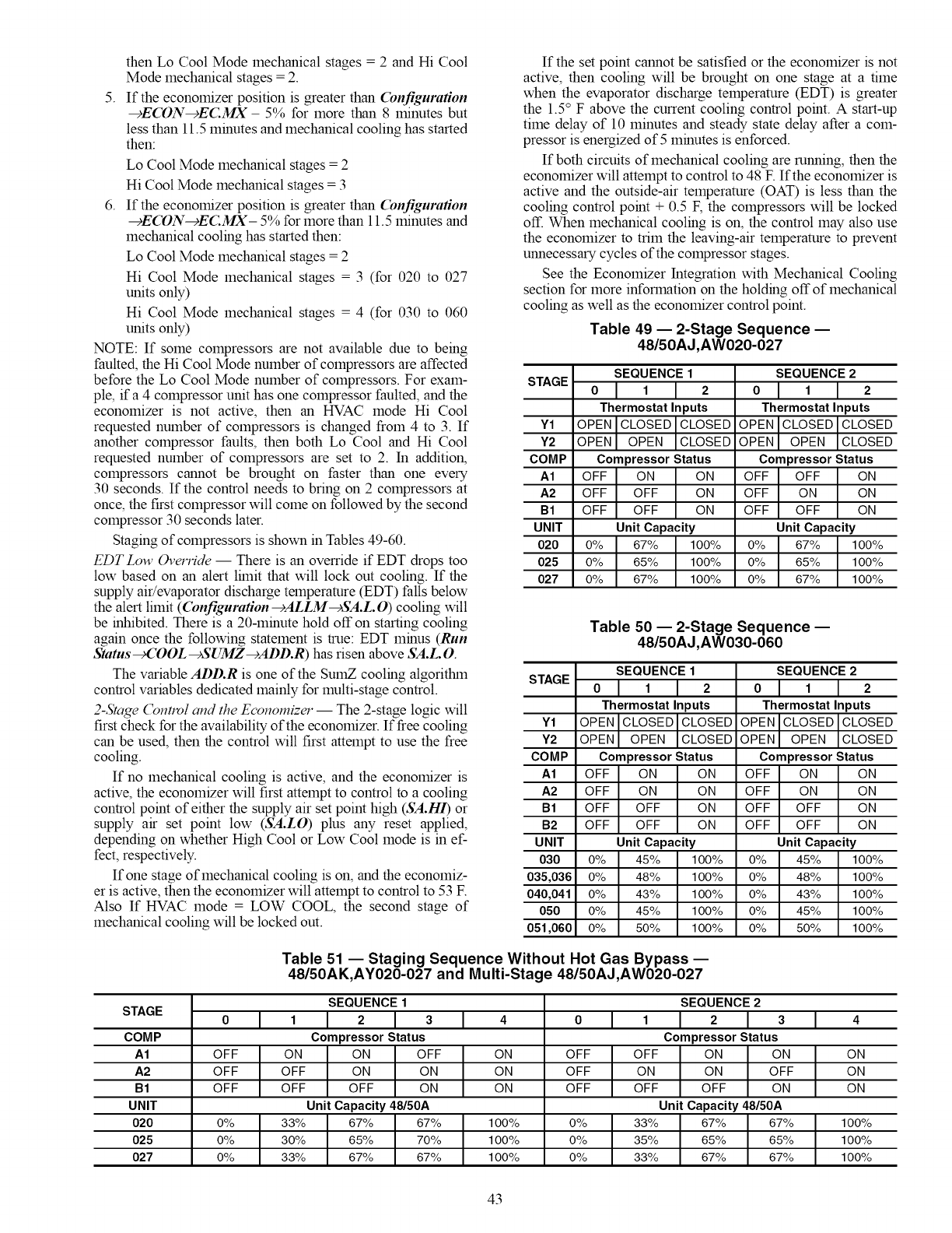
5.
then Lo Cool Mode mechanical stages = 2 and Hi Cool
Mode mechanical stages = 2.
If the economizer position is greater than (bnfiguration
-+ECON-+ECMX- 5% for more than 8 minutes but
less than 11.5 minutes and mechanical cooling has started
then:
Lo Cool Mode mechanical stages = 2
Hi Cool Mode mechanical stages = 3
6. If the economizer position is greater than (bnfiguration
-sECON-sEC.MX- 5% for more than 11.5 minutes and
mechanical cooling has started then:
Lo Cool Mode mechanical stages = 2
Hi Cool Mode mechanical stages = 3 (for 020 to 027
units only)
Hi Cool Mode mechanical stages = 4 (for 030 to 060
units only)
NOTE: If some compressors are not available due to being
faulted, the Hi Cool Mode number of compressors are affected
before the Lo Cool Mode number of compressors. For exam- STAGE
ple, if a 4 compressor unit has one compressor faulted, and the
economizer is not active, then an HVAC mode Hi Cool
requested number of compressors is changed from 4 to 3. If Y1
another compressor faults, then both Lo Cool and Hi Cool Y2
requested number of compressors are set to 2. In addition, COMP
compressors cannot be brought on faster than one every A1
30 seconds. If the control needs to bring on 2 compressors at A2
once, the first compressor will come on followed by the second B1
compressor 30 seconds later. UNIT
Staging of compressors is shown in Tables 49-60. 020
EDT Low Override -- There is an override if EDT drops too 025
low based on an alert lhnit that will lock out cooling. If the 027
supply air/evaporator discharge temperature (EDT) falls below
the alert limit ((bnfiguration---)ALLM--+SA.L.O) cooling will
be inhibited. There is a 20-minute hold off on starting cooling
again once the following statement is true: EDT minus (Run
Status _COOL--sSUMZ--sADD.R) has risen above SA.L.O.
The variable ADD.R is one of the SumZ cooling algofithin STAGE
control variables dedicated mainly for multi-stage control.
2-Stage (_ntlvl and the Economizer -- The 2-stage logic will
first check for the availability of the economizer. If free cooling Y1
can be used, then the control will first attempt to use the free Y2
cooling. COMP
If no mechanical cooling is active, and the economizer is A1
active, the economizer will first attempt to control to a cooling A2
control point of either the supply air set point high (SA.H1) or B1
supply air set point low (SA.LO) plus any reset applied, B2
depending on whether High Cool or Low Cool mode is in ef- UNIT
fect, respectively. 030
If one stage of mechanical cooling is on, and the economiz- 035,036
er is active, then the economizer will attempt to control to 53 E 040,041
Also If HVAC mode = LOW COOL, the second stage of 050
mechanical cooling will be locked out. 051,060
If the set point cannot be satisfied or the economizer is not
active, then cooling will be brought on one stage at a time
when the evaporator discharge temperature (EDT) is greater
the 1.5° F above the current cooling control point. A start-up
time delay of 10 minutes and steady state delay after a com-
pressor is energized of 5 minutes is enforced.
If both circuits of mechanical cooling are running, then the
economizer will attempt to control to 48 E If the economizer is
active and the outside-air temperature (OAT) is less than the
cooling control point + 0.5 F, the compressors will be locked
off. When mechanical cooling is on, the control may also use
the economizer to trim the leaving-air temperature to prevent
unnecessary cycles of the compressor stages.
See the Economizer Integration with Mechanical Cooling
section for more information on the holding off of mechanical
cooling as well as the economizer control point.
Table 49 -- 2-Stage Sequence --
48/50AJ,AW020-027
SEQUENCE 1
o l i I 2
Thermostat Inputs
OPEN CLOSED I CLOSED
I
OPEN OPEN CLOSED
Compressor Status
OFF ON ON
OFF OFF ON
OFF OFF ON
Unit Capacity
0% 67% 100%
0% 65% 100%
0% 67% 100%
SEQUENCE 2
01 1I2
Thermostat Inputs
OPEN CLOSED CLOSED
OPEN OPEN CLOSED
Compressor Status
OFF OFF ON
OFF ON ON
OFF OFF ON
Unit Capacity
0% 67% 100%
0% 65% 100%
0% 67% 100%
Table 50 -- 2-Stage Sequence --
48/50AJ,AW030-060
SEQUENCE 1
ol i I 2
Thermostat Inputs
OPEN CLOSEDI CLOSED
I
OPEN OPEN CLOSED
Compressor Status
OFF ON ON
OFF ON ON
OFF OFF ON
OFF OFF ON
Unit Capacity
0% 45% 100%
0% 48% 100%
0% 43% 100%
0% 45% 100%
0% 50% 100%
SEQUENCE 2
01 1I2
Thermostat Inputs
OPEN l CLOSED CLOSED
OPEN[ OPEN CLOSED
Compressor Status
OFF ON ON
OFF ON ON
OFF OFF ON
OFF OFF ON
Unit Capacity
0% 45% 100%
0% 48% 100%
0% 43% 100%
0% 45% 100%
0% 50% 100%
Table 51 -- Staging Sequence Without Hot Gas Bypass --
48/50AK,AY020-027 and Multi-Stage 48/50AJ,AW020-027
SEQUENCE 1 SEQUENCE 2
STAGE 0 1 2 3 4 0 1 2 3 4
COMP Compressor Status Compressor Status
A1 OFF ON ON OFF ON OFF OFF ON ON ON
A2 OFF OFF ON ON ON OFF ON ON OFF ON
B1 OFF OFF OFF ON ON OFF OFF OFF ON ON
UNIT Unit Capacity 48/50A Unit Capacity 48/50A
020 0% 33% 67% 67% 100% 0% 33% 67% 67% 100%
025 0% 30% 65% 70% 100% 0% 35% 65% 65% 100%
027 0% 33% 67% 67% 100% 0% 33% 67% 67% 100%
43
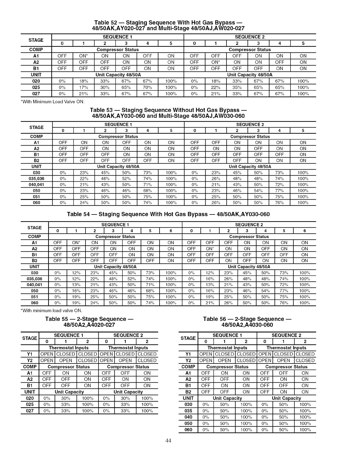
STAGE
COMP
A1
A2
B1
UNIT
020
025
027
I 1
OFF ON*
OFF OFF
OFF OFF
0% 18%
0% 17%
0% 21%
*With Minimum Load Valve ON,
Table 52 nStaging Sequence With Hot Gas Bypass
48/50AK,AY020-027 and Multi-Stage 48/50AJ,AW020-027
SEQUENCE 1
I2IaI4I s
Compressor Status
ON ON OFF ON
OFF ON ON ON
OFF OFF ON ON
Unit Capacity 48/50A
33% 67% 67% 100%
30% 65% 70% 100%
33% 67% 67% 100%
OFF
OFF
OFF
0%
0%
0%
I 1
SEQUENCE 2
I2Ia I 4 I s
Compressor Status
OFF OFF ON ON ON
ON* ON ON OFF ON
OFF OFF OFF ON ON
Unit Capacity 48/50A
18% 33% 67% 67% 100%
22% 35% 65% 65% 100%
21% 33% 67% 67% 100%
STAG E
COMP
A1
A2
B1
B2
UNIT
030
035,036
040,041
050
051
060
OFF
OFF
OFF
OFF
0%
0%
0%
0%
0%
0%
Table 53 -- Staging Sequence Without Hot Gas Bypass --
48/50AK,AY030-060 and Multi-Stage 48/50AJ,AW030-060
SEQUENCE 1
t I 2 I 3I 4 I 5
Compressor Status
ON ON OFF ON ON
OFF ON ON ON ON
OFF OFF ON ON ON
OFF OFF OFF OFF ON
Unit Capacity 48/50A
23% 45% 50% 73% 100%
22% 48% 52% 74% 100%
21% 43% 50% 71% 100%
23% 46% 46% 68% 100%
25% 50% 50% 75% 100%
24% 50% 50% 74% 100%
OFF
OFF
OFF
OFF
0%
0%
0%
0%
0%
0%
I 1
SEQUENCE 2
I 2 I 3 I 4 I 5
Compressor Status
OFF ON ON ON ON
ON ON OFF ON ON
OFF OFF OFF OFF ON
OFF OFF ON ON ON
Unit Capacity 48/50A
23% 45% 50% 73% 100%
26% 48% 48% 74% 100%
21% 43% 50% 72% 100%
23% 46% 54% 77% 100%
25% 50% 50% 75% 100%
26% 50% 50% 76% 100%
STAGE
COMP
A1
A2
B1
B2
UNIT
030
035,036
040,041
050
051
060
OFF
OFF
OFF
OFF
Table 54 -- Staging Sequence With Hot Gas Bypass -- 48/50AK,AY030-060
ON*
OFF
OFF
OFF
0% 12%
0% 12%
0% 13%
0% 16%
0% 19%
0% 19%
*With minimum load valve ON,
STAGE
Y1
Y2
COMP
A1
A2
B1
UNIT
020
025
027
SEQUENCE 1
I2I3I4I5I 6
Compressor Status
ON ON OFF ON ON
OFF ON ON ON ON
OFF OFF ON ON ON
OFF OFF OFF OFF ON
Unit Capacity 48/50A
23% 45% 50% 73% 100%
22% 48% 52% 74% 100%
21% 43% 50% 71% 100%
23% 46% 46% 68% 100%
25% 50% 50% 75% 100%
24% 50% 50% 74% 100%
SEQUENCE 2
o I1 12 13 14 15 I 6
Compressor Status
OFF OFF OFF ON ON ON ON
OFF ON* ON ON OFF ON ON
OFF OFF OFF OFF OFF OFF ON
OFF OFF ON OFF ON ON ON
Unit Capacity 48/50A
0% 12% 23% 45% 50% 73% 100%
0% 16% 26% 48% 48% 74% 100%
0% 13% 21% 43% 50% 72% 100%
0% 16% 23% 46% 54% 77% 100%
0% 19% 25% 50% 50% 75% 100%
0% 21% 26% 50% 50% 76% 100%
Table 55 -- 2-Stage Sequence --
48/50A2,A4020-027
SEQUENCE 1
o l 1 I 2
Thermostat Inputs
OPEN CLOSED I CLOSED
I
OPEN OPEN CLOSED
Compressor Status
OFF ON ON
OFF OFF ON
OFF OFF ON
Unit Capacity
0% 30% 100%
0% 33% 100%
0% 33% 100%
SEQUENCE 2
01 1I 2
Thermostat Inputs
OPEN CLOSED JCLOSED
I
OPEN OPEN CLOSED
Compressor Status
OFF OFF ON
OFF ON ON
OFF OFF ON
Unit Capacity
0% 30% 100%
0% 33% 100%
0% 33% 100%
STAGE
Y1
Y2
COMP
A1
A2
B1
B2
UNIT
030
035
040
050
060
Table 56 -- 2-Stage Sequence --
48/50A2,A4030-060
SEQUENCE 1
o l 1 I 2
Thermostat Inputs
OPEN CLOSED CLOSED
OPEN OPEN CLOSED
Compressor Status
OFF ON ON
OFF OFF ON
OFF ON ON
OFF OFF ON
Unit Capacity
0% 50% 100%
0% 50% 100%
0% 50% 100%
0% 50% 100%
0% 50% 100%
SEQUENCE 2
01 1I 2
Thermostat Inputs
OPEN CLOSED JCLOSED
I
OPEN OPEN CLOSED
Compressor Status
OFF OFF ON
OFF ON ON
OFF OFF ON
OFF ON ON
Unit Capacity
0% 50% 100%
0% 50% 100%
0% 50% 100%
0% 50% 100%
0% 50% 100%
44
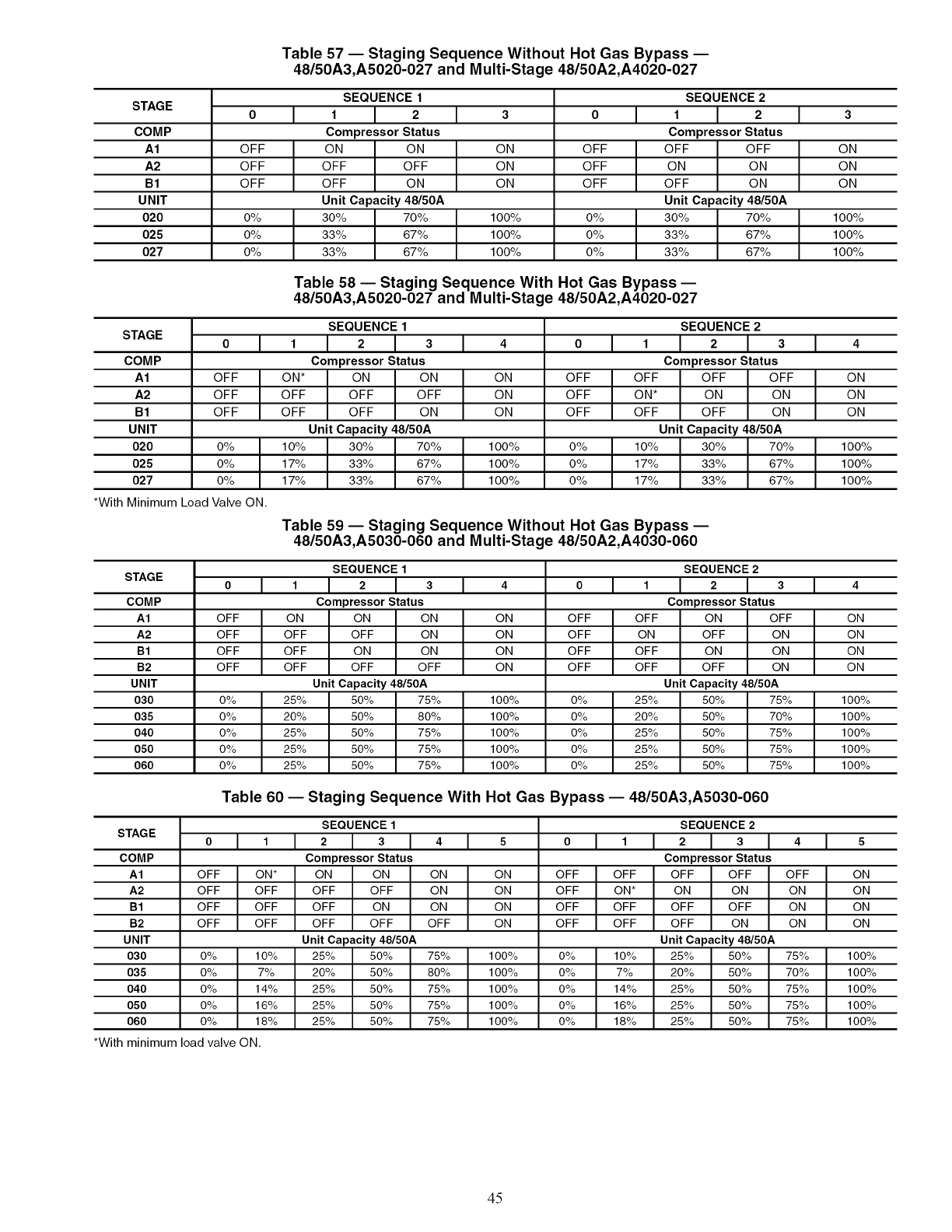
STAGE
COMP
A1
A2
B1
UNIT
020
025
027
STAGE
COMP
A1
A2
B1
UNIT
020
025
027
OFF
OFF
OFF
0%
0%
0%
Table 57 -- Staging Sequence Without Hot Gas Bypass --
48/50A3,A5020-027 and Multi-Stage 48/50A2,A4020-027
SEQUENCE 1
1I 2
Compressor Status
ON ON
OFF OFF
OFF ON
Unit Capacity 48/50A
30% 70%
33% 67%
33% 67%
ON
ON
ON
100%
100%
100%
OFF
OFF
OFF
0%
0%
0%
SEQUENCE 2
1I 2
Compressor Status
OFF OFF
ON ON
OFF ON
Unit Capacity 48/50A
30% 70%
33% 67%
33% 67%
OFF
OFF
OFF
0%
0%
0%
*With Minimum Load Valve ON.
Table 58 uStaging Sequence With Hot Gas Bypass --
48/50A3,A5020-027 and Multi-Stage 48/50A2,A4020-027
SEQUENCE 1
1 2 3
Compressor Status
ON* ON ON
OFF OFF OFF
OFF OFF ON
Unit Capacity 48/50A
10% 30% 70%
17% 33% 67%
17% 33% 67%
ON
ON
ON
100%
100%
100%
OFF
OFF
OFF
0%
0%
0%
SEQUENCE 2
123
Compressor Status
OFF OFF OFF
ON* ON ON
OFF OFF ON
Unit Capacity 48/50A
10% 30% 70%
17% 33% 67%
17% 33% 67%
STAGE
COMP
A1
A2
B1
B2
UNIT
030
035
040
O5O
060
OFF
OFF
OFF
OFF
0%
0%
0%
0%
0%
Table 59 -- Staging Sequence Without Hot Gas Bypass --
48/50A3,A5030-060 and Multi-Stage 48/50A2,A4030-060
ON
OFF
OFF
OFF
25%
20%
25%
25%
25%
SEQUENCE 1
I2Ia
Compressor Status
ON ON
OFF ON
ON ON
OFF OFF
Unit Capacity 48/50A
50% 75%
50% 80%
50% 75%
50% 75%
50% 75%
ON
ON
ON
ON
100%
100%
100%
100%
100%
OFF
OFF
OFF
OFF
0%
0%
0%
0%
0%
I1
OFF
ON
OFF
OFF
25%
20%
25%
25%
25%
SEQUENCE 2
I2I3
Compressor Status
ON OFF
OFF ON
ON ON
OFF ON
Unit Capacity 48/50A
50% 75%
50% 70%
50% 75%
50% 75%
50% 75%
STAG E
COMP
A1
A2
B1
B2
UNIT
030
035
040
O5O
060
Table 60 -- Staging Sequence With Hot Gas Bypass -- 48/50A3,A5030-060
0 I t
OFF ON*
OFF OFF
OFF OFF
OFF OFF
0% 10%
0% 7%
0% 14%
0% 16%
0% 18%
*With minimum load valve ON.
SEQUENCE 1
2 I 3 I 4 I s
Compressor Status
ON ON ON ON
OFF OFF ON ON
OFF ON ON ON
OFF OFF OFF ON
Unit Capacity 48/50A
25% 50% 75% 100%
20% 50% 80% 100%
25% 50% 75% 100%
25% 50% 75% 100%
25% 50% 75% 100%
SEQUENCE 2
0I t I 2 I a I 4
Compressor Status
OFF OFF OFF OFF OFF
OFF ON* ON ON ON
OFF OFF OFF OFF ON
OFF OFF OFF ON ON
Unit Capacity 48/50A
0% 10% 25% 50% 75%
0% 7% 20% 50% 70%
0% 14% 25% 50% 75%
0% 16% 25% 50% 75%
0% 18% 25% 50% 75%
ON
ON
ON
100%
100%
100%
ON
ON
ON
100%
100%
100%
ON
ON
ON
ON
100%
100%
100%
100%
100%
ON
ON
ON
ON
100%
100%
100%
100%
100%
45
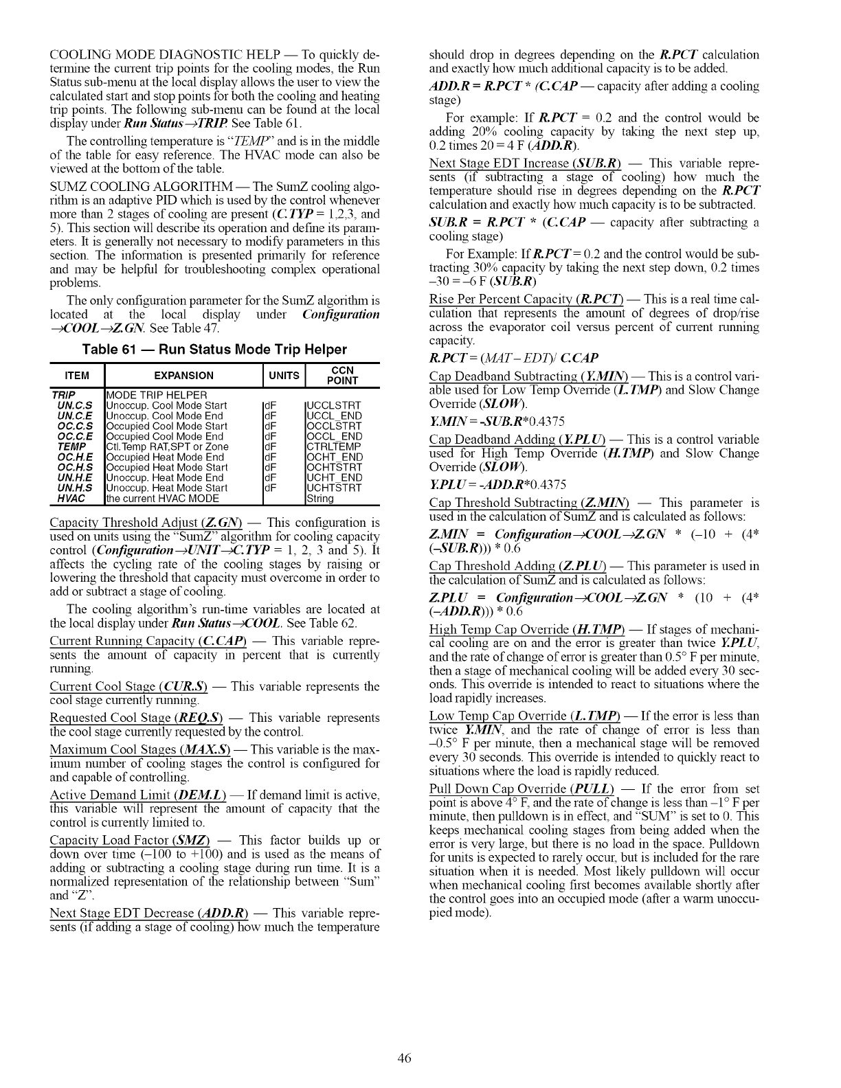
COOLING MODE DIAGNOSTIC HELP -- To quickly de-
termine the current trip points for the cooling modes, the Run
Stares sub-menu at the local display allows the user to view the
calculated start and stop points for both the cooling and heating
trip points. The following sub-menu can be found at the local
display under Run Status--+TRIP. See Table 61.
The controlling temperature is "TEMP" and is in the middle
of the table for easy reference. The HVAC mode can also be
viewed at the bottom of the table.
SUMZ COOL1NG ALGORITHM -- The SumZ cooling algo-
ritlnn is an adaptive PID which is used by the control whenever
more than 2 stages of cooling are present (C TYP = 1,2,3, and
5). This section will describe its operation and define its param-
eters. It is generally not necessary to modify parameters in this
section. The information is presented prhnarily for reference
and may be helpful for troubleshooting complex operational
problems.
The only configuration parameter for the SumZ algorithin is
located at the local display under Configuration
_'OOL--dZGN. See Table 47.
Table 61 -- Run Status Mode Trip Helper
UNITS CCN
ITEM EXPANSION POINT
TRIP
UN. C.S
UN.C.E
OC.C.S
OC.C.E
TEMP
OC.H.E
OC.H.S
UN.H.E
UN.H.S
HVAC
MODE TRIP HELPER
Unoccup. Cool Mode Start dF
Unoccup. Cool Mode End dF
Occupied Cool Mode Start dF
Occupied Cool Mode End dF
CtI.Temp RAT, SPT or Zone dF
Occupied Heat Mode End dF
Occupied Heat Mode Start dF
Unoccup. Heat Mode End dF
Unoccup. Heat Mode Start dF
the current HVAC MODE
UCCLSTRT
UCCL END
OCCLSTRT
OCCL END
CTRLTEMP
OCHT END
OCHTSTRT
UCHT END
UCHTSTRT
String
Capacity Threshold Adjust (Z. GN) -- This configuration is
used on units using the "SumZ" algofithin for cooling capacity
control (Configuration-+UNIT_:TYP = 1, 2, 3 and 5). It
affects the cycling rate of the cooling stages by raising or
lowering the threshold that capacity must overcome in order to
add or subtract a stage of cooling.
The cooling algofithin's run-time variables are located at
the local display under Run Status_'OOL. See Table 62.
Current Running Capacity (C(5tP) -- This variable repre-
sents the amount of capacity in percent that is currently
running.
Current Cool Stage (CUR.S) -- This variable represents the
cool stage currently running.
Requested Cool Stage (REQ.S) -- This variable represents
the cool stage currently requested by the control.
Maximum Cool Stages (MAX.S) -- This variable is the max-
imum number of cooling stages the control is configured for
and capable of controlling.
Active Demand Limit (DEM.L) -- If demand lhnit is active,
this variable will represent the amount of capacity that the
control is currently lhnited to.
Capacity Load Factor (SMZ) -- This factor builds up or
down over time (-100 to +100) and is used as the means of
adding or subtracting a cooling stage during mn time. It is a
normalized representation of the relationship between "Sum"
and "Z".
Next Stage EDT Decrease (ADD.R) -- This variable repre-
sents (if adding a stage of cooling) how much the temperature
should drop in degrees depending on the R.PCT calculation
and exactly how much additional capacity is to be added.
ADD.R =R.PCT *(C CAP-- capacity after adding a cooling
stage)
For example: If R.PCT = 0.2 and the control would be
adding 20% cooling capacity by taking the next step up,
0.2 times 20 = 4 F (ADD.R).
Next Stage EDT Increase (SUB.R) -- This variable repre-
sents (if subtracting a stage of cooling) how much the
temperature should rise in degrees depending on the R.PCT
calculation and exactly how much capacity is to be subtracted.
SUB.R =R.PCT * (C.(5tP -- capacity after subtracting a
cooling stage)
For Example: IfR, PCT = 0.2 and the control would be sub-
tracting 30% capacity by taking the next step down, 0.2 times
-30 = -6 F (SUB.R)
Rise Per Percent Capacity (R.PCT) -- This is a real time cal-
culation that represents the amount of degrees of drop/rise
across the evaporator coil versus percent of current running
capacity.
R.PCT = (MAT- ED_/ C. CAP
Cap Deadband Subtracting (EMIN) -- This is a control vari-
able used for Low Temp Override (L. TMP) and Slow Change
Override (SLOW).
Y.MIN = -SUB.R*0.4375
Cap Deadband Adding (YPLU) --This is a control variable
used for High Temp Ovemde (H.TMP) and Slow Change
Ovemde (SLOW).
YPLU = -ADD.R*0.4375
Cap Threshold Subtracting (Z.MIN) -- This parameter is
used in the calculation of SumZ and is calculated as follows:
Z.MIN =(bnfiguration_'OOL--cZGN * (-10 + (4*
(-SUB.R))) * 0.6
Cap Threshold Adding (Z.PLU) -- This parameter is used in
the calculation of SumZ and is calculated as follows:
Z.PLU =(bnfiguration_'OOL--cZGN * (10 + (4*
(-ADD.R))) * 0.6
High Telnp Cap Override (H. TMP) -- If stages of mechani-
cal cooling are on and the error is greater than twice Y..PLU,
and the rate of change of error is greater than 0.5° F per minute,
then a stage of mechanical cooling will be added every 30 sec-
onds. This ovemde is intended to react to situations where the
load rapidly increases.
Low Temp Cap Override (L. TMP) -- If the error is less than
twice Y.MIN, and the rate of change of error is less than
-0.5 ° F per minute, then a mechanical stage will be removed
every 30 seconds. This override is intended to quickly react to
situations where the load is rapidly reduced.
Pull Down Cap Override (PULL) -- If the error from set
point is above 4° F, and the rate of change is less than -1 ° F per
minute, then pulldown is in effect, and "SUM" is set to 0. This
keeps mechanical cooling stages from being added when the
error is very large, but there is no load in the space. Pulldown
for units is expected to rarely occur, but is included for the rare
situation when it is needed. Most likely pulldown will occur
when mechanical cooling first becomes available shortly after
the control goes into an occupied mode (after a warm unoccu-
pied mode).
46
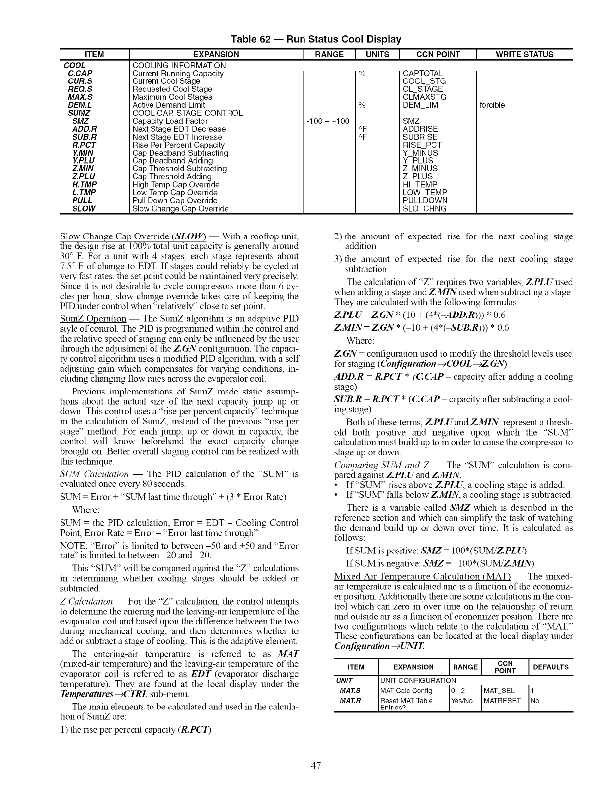
ITEM
COOL
C.CAP
CUR.S
REQ.S
MAX.S
DEM.L
SUMZ
SMZ
ADD.R
SUB.R
R.PCT
Y.MIN
ZPLU
ZMIN
ZPLU
H.TMP
L. TMP
PULL
SLOW
Table 62 -- Run Status Cool Display
EXPANSION
COOLING INFORMATION
Current Running Capacity
Current Cool Stage
Requested Cool Stage
Maximum Cool Stages
Active Demand Limit
COOL CAR STAGE CONTROL
Capacity Load Factor
1RANGE .I, UNITS [ CCNPOINT JWRITE STATUS
-1O0 - +1O0
%
%
CAPTOTAL
COOL STG
CL ST-AGE
CL_IAXSTG
DEM_LIM
SMZ
forcible
Next Stage EDT Decrease
Next Stage EDT Increase
Rise Per Percent Capacity
Cap Deadband Subtracting
Cap Deadband Adding
Cap Threshold Subtracting
Cap Threshold Adding
High Temp Cap Override
Low Temp Cap Override
Pull Down Cap Override
Slow Change Cap Override
^F ADDRISE
^F SUBRISE
RISE PCT
Y MI_IUS
YPLUS
ZMINUS
Z PLUS
HI- TEMP
LOW TEMP
PULL-DOWN
SLO CHNG
Slow Change Cap Override (SLOW) -- With a rooftop unit,
the design rise at 100% total unit capacity is generally around
30 ° F. For a unit with 4 stages, each stage represents about
7.5 ° F of change to EDT. If stages could reliably be cycled at
very fast rates, the set point could be maintained very precisely.
Since it is not desirable to cycle compressors more than 6 cy-
cles per hour, slow change ovemde takes care of keeping the
PID under control when "relatively" close to set point.
SumZ Operation -- The SumZ algorithin is an adaptive PID
style of control. The PID is progralmned within the control and
the relative speed of staging can only be influenced by the user
through the adjustment of the Z GN configuration. The capaci-
ty control algorithin uses a modified PID algorithin, with a self
adjusting gain which compensates for varying conditions, in-
cluding changing flow rates across the evaporator coil.
Previous hnplementations of SumZ made static assump-
tions about the actual size of the next capacity jump up or
down. This control uses a "rise per percent capacity" technique
in the calculation of SumZ, instead of the previous "rise per
stage" method. For each jump, up or down in capacity, the
control will know beforehand the exact capacity change
brought on. Better overall staging control can be realized with
this technique.
SUM Calculation -- The PID calculation of the "SUM" is
evaluated once every 80 seconds.
SUM = Error + "SUM last thne through" + (3 * Error Rate)
Where:
SUM = the PID calculation, Error = EDT - Cooling Control
Point, Error Rate = Error- "Error last time through"
NOTE: "Error" is limited to between-50 and +50 and "Error
rate" is limited to between -20 and +20.
This "SUM" will be compared against the "Z" calculations
in determining whether cooling stages should be added or
subtracted.
Z Calculation -- For the "Z" calculation, the control attempts
to determine the entering and the leaving-air temperature of the
evaporator coil and based upon the difference between the two
during mechanical cooling, and then determines whether to
add or subtract a stage of cooling. This is the adaptive element.
The entering-air temperature is referred to as MAT
(mixed-air temperature) and the leaving-air temperature of the
evaporator coil is referred to as EDT (evaporator discharge
temperature). They are found at the local display under the
Temperatures _C'TRL sub-menu.
The main elements to be calculated and used in the calcula-
tion of SumZ are:
1) the rise per percent capacity (R.PCT)
2) the amount of expected rise for the next cooling stage
addition
3) the amount of expected rise for the next cooling stage
subtraction
The calculation of"Z" requires two variables, ZPL Uused
when adding a stage and Z.MINused when subtracting a stage.
They are calculated with the following formulas:
Z.PLU= ZGN * (10 + (4*(-ADD.R))) * 0.6
Z.MIN= ZGN * (-10 + (4*(-SUB.R))) * 0.6
Where:
Z.GN = configuration used to modify the threshold levels used
for staging ( Configuration-gC OOL -gZ GN)
ADD.R =R.PCT *(C CAP - capacity after adding a cooling
stage)
SUB.R =R.PCT * (C CAP- capacity after subtracting a cool-
ing stage)
Both of these terms, Z.PLUand Z.MIN, represent a thresh-
old both positive and negative upon which the "SUM"
calculation must build up to in order to cause the compressor to
stage up or down.
(_mparing SUM and Z -- The "SUM" calculation is com-
pared against ZPL Uand Z.MIN.
•If"SUM" rises above Z.PLU, a cooling stage is added.
• If"SUM" falls belowZ.MIN, a cooling stage is subtracted.
There is a variable called SMZ which is described in the
reference section and which can shnplify the task of watching
the demand build up or down over time. It is calculated as
follows:
If SUM is positive: SMZ = 100*(SUM!ZPLU)
If SUM is negative: SMZ = - 100 *(SUM!ZMIN)
Mixed Air Temperature Calculation (MAT) -- The mixed-
air temperature is calculated and is a function of the economiz-
er position. Additionally there are some calculations in the con-
trol which can zero in over time on the relationship of return
and outside air as a function of economizer position. There are
two configurations which relate to the calculation of "MAT."
These configurations can be located at the local display under
Configuration -gUNIT.
ITEM
UNIT
MAZS
MAZR
CON I
EXPANSION RANGE POINT I DEFAULTS
I
UNIT CONFIGURATION
MAT Calc Config 0 - 2 MAT SEL Nlo
Reset MAT Table Yes/No MATRESET
Entr es?
47
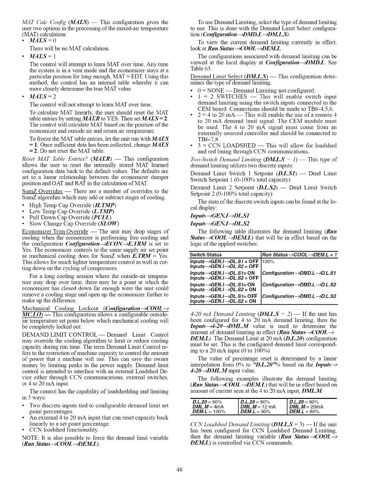
MAT Cale (_nfig (MAT.S) -- This configuration gives the
user two options in the processing of the mixed-air temperature
(MAT) calculation:
•MAT.S = 0
There will be no MAT calculation.
• MAT.S = 1
The control will attempt to learn MAT over time. Any time
the system is in a vent mode and the economizer stays at a
particular position for long enough, MAT = EDT. Using this
method, the control has an internal table whereby it can
more closely determine the true MAT value.
MAT.S = 2
The control will not attempt to learn MAT over thne.
To calculate MAT linearly, the user should reset the MAT
table entries by setting MAT.R to YES. Then set MAT.S = 2.
The control will calculate MAT based on the position of the
economizer and outside air and return air temperature.
To freeze the MAT table entries, let the unit run withMAT.S
= 1. Once sufficient data has been collected, change MAT.S
= 2. Do not reset the MAT table.
Reset MAT Table Entries? (MAT.R) -- This configuration
allows the user to reset the internally stored MAT learned
configuration data back to the default values. The defaults are
set to a linear relationship between the economizer damper
position and OAT and RAT in the calculation of MAT.
SumZ Overrides -- There are a number of overrides to the
SumZ algofitlun which may add or subtract stages of cooling.
•High Temp Cap Override (H. TMP)
•Low Temp Cap Override (L. TMP)
•Pull Down Cap Override (PULL)
•Slow Change Cap Override (SLOW)
Economizer Trim Override -- The unit may drop stages of
cooling when the economizer is performing free cooling and
the configuration Configuration--+ECON--+E.TRM is set to
Yes. The economizer controls to the same supply air set point
as mechanical cooling does for SumZ when E. TRM = Yes.
This allows for much tighter temperature control as well as cut-
ting down on the cycling of compressors.
For a long cooling session where the outside-air tempera-
rare may drop over time, there may be a point at which the
economizer has closed down far enough were the unit could
remove a cooling stage and open up the economizer further to
make up the difference.
Mechanical Coolin_ Lockout ((bnfiguration _'OOL--€
MCLO) -- This configuration allows a configurable outside-
air temperature set point below which mechanical cooling will
be completely locked out.
DEMAND LIMIT CONTROL -- Demand Lfinit Control
may override the cooling algoritlun to limit or reduce cooling
capacity during run time. The term Demand Lfinit Control re-
fers to the restriction of machine capacity to control the amount
of power that a machine will use. This can save the owner
money by limiting peaks in the power supply. Demand limit
control is intended to interface with an external Loadshed De-
vice either through CCN colrnnunications, external switches,
or 4 to 20 mA input.
The control has the capability of loadshedding and limiting
in 3 ways:
•Two discrete inputs tied to configurable demand limit set
point percentages.
•An external 4 to 20 mA input that can reset capacity back
linearly to a set point percentage.
•CCN loadshed functionality.
NOTE: It is also possible to force the demand limit variable
(Run Status--+(DOL -+DEM.L).
To use Demand Lhniting, select the type of demand limiting
to use. This is done with the Demand Lhnit Select configura-
tion ((bnfiguration -+DMD.L -+DM.L.S).
To view the current demand lflniting currently in effect,
look at Run Status _'OOL -+DEM.L.
The configurations associated with demand lhniting can be
viewed at the local display at (bnfiguration--_DMD.L. See
Table 63.
Demand Limit Select (DM.L.S) -- This configuration deter-
mines the type of demand lhniting.
•0 = NONE -- Demand Limiting not configured.
•1 = 2 SWITCHES -- This will enable switch input
demand limiting using the switch inputs connected to the
CEM board. Connections should be made to TB6-4,5,6.
•2 = 4 to 20 mA -- This will enable the use of a remote 4
to 20 mA demand limit signal. The CEM module must
be used. The 4 to 20 mA signal must come from an
externally sourced controller and should be connected to
TB6-7,8.
•3 = CCN LOADSHED -- This will allow for loadshed
and red lining through CCN communications.
Two-Switch Demand Limiting (DM.L.S l) -- This type of
demand limiting utilizes two discrete inputs:
Demand Limit Switch 1 Setpoint (D.L.S1) -- Dmd Limit
Switch Setpoint 1 (0-100% total capacity)
Demand Limit 2 Setpoint (D.L.S2) -- Dmd Limit Switch
Setpoint 2 (0-100% total capacity)
The state of the discrete switch inputs can be found at the lo-
cal display:
Inputs"_GEN.I-+DL.S1
Inputs" _GEN. I--cDL.S2
The following table illustrates the demand limiting (Run
Status_'OOL-+DEM.L) that will be in effect based on the
logic of the applied switches:
Switch Status
Inputs-->GEN.I-->DL.S1 = OFF
Inputs-->GEN.I-->DL.S2 = OFF
Inputs-->GEN.I-->DL.Sl= ON
Inputs-->GEN.I-->DL.S2 = OFF
Inputs-->GEN.I-->DL.Sl= ON
Inputs-->GEN.I-->DL.S2 = ON
Inputs-->GEN.I-->DL.Sl= OFF
Inputs--)GEN.I--)DL.S2 = ON
Run Status--)COOL--)DEM.L = 1
100%
Configuration--)DMD.L--)D.L.Sl
Configuration--)DMD.L--)D.L.S2
Configuration--)DMD.L--)D.L.S2
4-20 mA Demand Limiting (DM.L.S 2) -- If the unit has
been configured for 4 to 20 mA demand limiting, then the
Inputs--c4-20--cDML.M value is used to determine the
amount of demand limiting in effect (Run Status _'OOL--+
DEM.L). The Demand Limit at 20 mA (D.L.20) configuration
must be set. This is the configured demand limit correspond-
ing to a 20 mA input (0 to 100%).
The value of percentage reset is determined by a linear
interpolation from 0% to "D.L.20"% based on the Inputs--€
4-20--¢DML.M input value.
The following examples illustrate the demand lfiniting
(Run Status_'OOL-+DEM.L) that will be in effect based on
amount of current seen at the 4 to 20 mA input, DML.M.
D.L.20 = 80% ID.L.20 = 80% ID.L.20 = 80%
DML.M = 4mA I DML.M = 12 mA I DML.M = 20mADEM.L = 100% DEM.L = 90% DEM.L = 80%
CCN Loadshed Demand Limiting (DM.L.S = 3) -- If the unit
has been configured for CCN Loadshed Demand Limiting,
then the demand lhniting variable (Run Status_'OOL--+
DEM.L) is controlled via CCN colmnands.
48
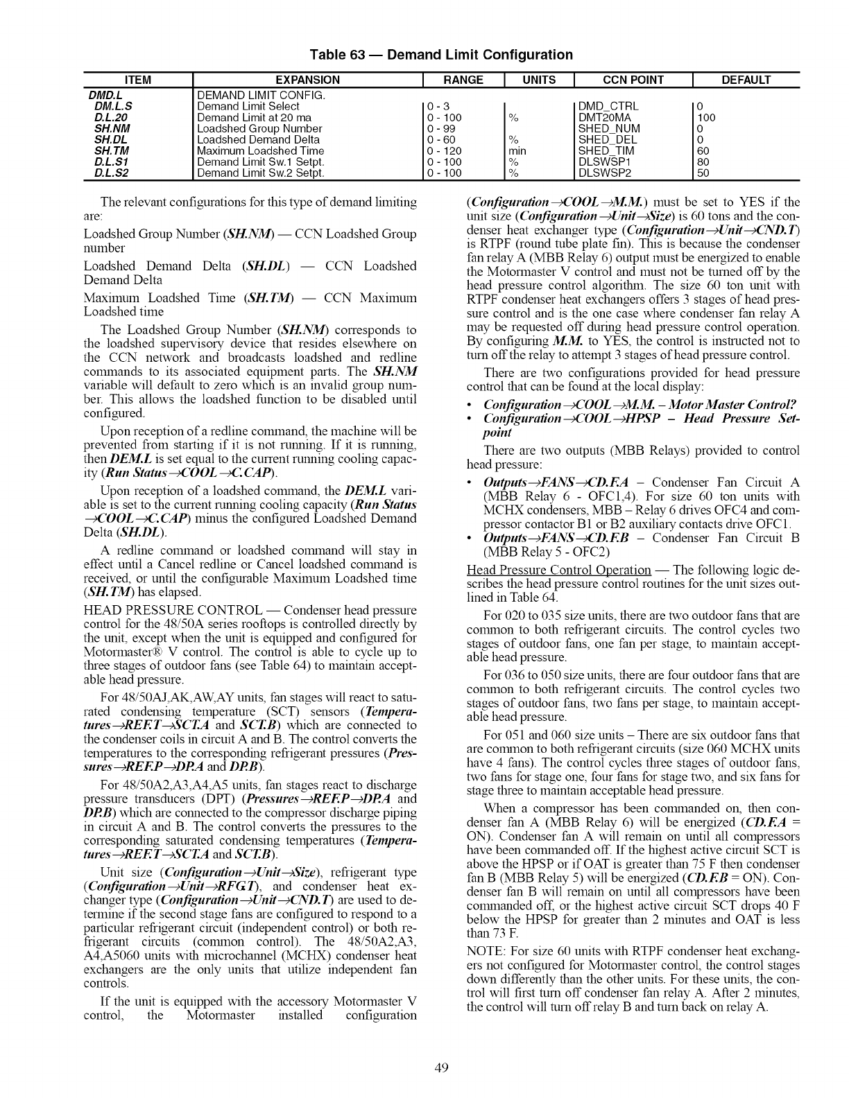
ITEM
DMD.L
DM.L.S
D.L.20
SH.NM
SH.DL
SH. TM
D.L.S1
D.L.S2
Table 63 -- Demand Limit Configuration
EXPANSION
DEMAND LIMIT CONFIG.
Demand Limit Select
Demand Limit at 20 ma
Loadshed Group Number
Loadshed Demand Delta
Maximum Loadshed Time
Demand Limit Sw.1 Setpt.
Demand Limit Sw.2 Setpt.
I RANGE I CCN POINTI UNITS
0-3 %
O- 100
0 - 99
0 - 60 %.
O- 120 I mm
0 - 100 '/o
0 - 100 %
I DEFAULT
DMD CTRL i
DMT2-OMA O0
SHED NUM
SHED DEL
SHED TIM _
DLSWSP1 80
DLSWSP2
The relevant configurations for this type of demand limiting
are:
Loadshed Group Number (SH.NM) -- CCN Loadshed Group
number
Loadshed Demand Delta (SH.DL) -- CCN Loadshed
Demand Delta
Maximum Loadshed Time (SH.TM) -- CCN Maximum
Loadshed time
The Loadshed Group Number (SH.NM) corresponds to
the loadshed supervisory device that resides elsewhere on
the CCN network and broadcasts loadshed and redline
cognnands to its associated equipment parts. The SH.NM
variable will default to zero which is an invalid group num-
ber. This allows the loadshed function to be disabled until
configured.
Upon reception of a redline cognnand, the machine will be
prevented from starting if it is not running. If it is running,
then DEM.L is set equal to the current running cooling capac-
ity (Run Status _COOL _C CAP).
Upon reception of a loadshed colmnand, the DEM.L vari-
able is set to the current running cooling capacity (Run Status
_COOL_(LCAP) minus the configured Loadshed Demand
Delta (SH.DL).
Aredline colmnand or loadshed colmnand will stay in
effect until a Cancel redline or Cancel loadshed colmnand is
received, or until the configurable Maximum Loadshed time
(SH. TM) has elapsed.
HEAD PRESSURE CONTROL -- Condenser head pressure
control for the 48/50A series rooftops is controlled directly by
the unit, except when the unit is equipped and configured for
Motormaster(R) V control. The control is able to cycle up to
three stages of outdoor fans (see Table 64) to maintain accept-
able head pressure.
For 48/50AJ,AK,AW, AY units, fan stages will react to sam-
rated condensing temperature (SCT) sensors (Tempera-
tures--+REET--+SCT.A and SCT.B) which are connected to
the condenser coils in circuit Aand B. The control converts the
temperatures to the corresponding refrigerant pressures (Pres-
sures--cREEP -+DRA and DRB).
For 48/50A2,A3,A4,A5 units, fan stages react to discharge
pressure transducers (DPT) (Pressures--cREEP-+DRA and
DRB) which are connected to the compressor discharge piping
in circuit A and B. The control converts the pressures to the
corresponding saturated condensing temperatures (Tempera-
tures--+REE T--+SCT.A and SCT.B).
Unit size (Configuration-cUnit-cSize), refrigerant type
(Configuration-+Unit-+RFG1), and condenser heat ex-
changer type (Configuration-+Unit-+(ND. 1) are used to de-
termine if the second stage fans are configured to respond to a
particular refrigerant circuit (independent control) or both re-
frigerant circuits (colmnon control). The 48/50A2,A3,
A4,A5060 units with microchannel (MCHX) condenser heat
exchangers are the only units that utilize independent fan
controls.
If the unit is equipped with the accessory Motormaster V
control, the Motormaster installed configuration
((bnfiguration--cCOOL--_M.M.) must be set to YES if the
unit size ((bnfiguration--+Unit--cSize) is 60 tons and the con-
denser heat exchanger type ((bnfiguration--cUnit--cCND.1)
is RTPF (round robe plate fin). This is because the condenser
fan relay A(MBB Relay 6) output must be energized to enable
the Motormaster V control and must not be mined off by the
head pressure control algorithin. The size 60 ton unit with
RTPF condenser heat exchangers offers 3 stages of head pres-
sure control and is the one case where condenser fan relay A
may be requested off during head pressure control operation.
By configuring M.M. to YES, the control is instructed not to
turn off the relay to attempt 3 stages of head pressure control.
There are two configurations provided for head pressure
control that can be found at the local display:
•(bnfiguration _COOL--_M.M. - Motor Master (bntrol?
• (bnfiguration-+COOL--cHPSP- Head Pressure Set-
point
There are two outputs (MBB Relays) provided to control
head pressure:
• Outputs-cFANS-cCD.EA - Condenser Fan Circuit A
(MBB Relay 6 - OFC1,4). For size 60 ton units with
MCHX condensers, MBB - Relay 6 drives OFC4 and com-
pressor contactor B 1 or B2 auxiliary contacts drive OFC 1.
• Outputs-cFANS-cCD.EB - Condenser Fan Circuit B
(MBB Relay 5 - OFC2)
Head Pressure Control Operation -- The following logic de-
scribes the head pressure control routines for the unit sizes out-
lined in Table 64.
For 020 to 035 size units, there are two outdoor fans that are
colrnnon to both refrigerant circuits. The control cycles two
stages of outdoor fans, one fan per stage, to maintain accept-
able head pressure.
For 036 to 050 size units, there are four outdoor fans that are
colrnnon to both refrigerant circuits. The control cycles two
stages of outdoor fans, two fans per stage, to maintain accept-
able head pressure.
For 051 and 060 size units - There are six outdoor fans that
are colrnnon to both refrigerant circuits (size 060 MCHX units
have 4 fans). The control cycles three stages of outdoor fans,
two fans for stage one, four fans for stage two, and six fans for
stage three to maintain acceptable head pressure.
When a compressor has been colrnnanded on, then con-
denser fan A (MBB Relay 6) will be energized (CD.EA =
ON). Condenser fan A will remain on until all compressors
have been cognnanded off. If the highest active circuit SCT is
above the HPSP or if OAT is greater than 75 F then condenser
fan B (MBB Relay 5) will be energized (CD.EB = ON). Con-
denser fan B will remain on until all compressors have been
colrnnanded off, or the highest active circuit SCT drops 40 F
below the HPSP for greater than 2 minutes and OAT is less
than 73 E
NOTE: For size 60 units with RTPF condenser heat exchang-
ers not configured for Motormaster control, the control stages
down differently than the other units. For these units, the con-
trol will first turn off condenser fan relay A. After 2 minutes,
the control will turn offrelay B and turn back on relay A.
49
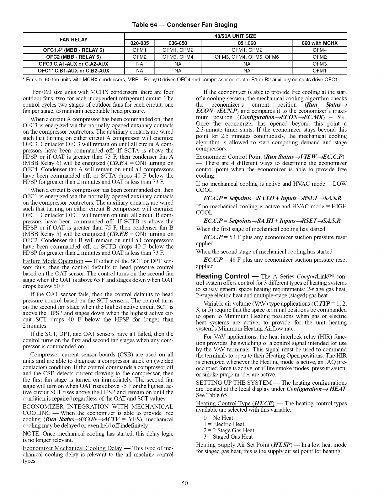
Table 64 -- Condenser Fan Staging
FAN RELAY
OFC1,4" (MBB - RELAY 6)
OFC2 (MBB - RELAY 5)
OFC3 C.A1-AUX or C.A2-AUX
OFCI* C.B1-AUX or C.B2-AUX
020-035 036-050
OFM1 OFM1, OFM2
OFM2 OFM3, OFM4
NA NA
NA NA
48/50A UNIT SIZE
051,060
OFM1, OFM2
OFM3, OFM4, OFM5, OFM6
NA
NA
060 with MCHX
OFM4
OFM2
OFM3
OFM1
* For size 60 ton units with MCHX condensers, MBB - Relay 6 drives OFC4 and compressor contactor B1 or B2 auxiliary contacts drive OFC1.
For 060 size units with MCHX condensers, there are four
outdoor fans, two for each independent refrigerant circuit. The
control cycles two stages of outdoor fans for each circuit, one
fan per stage, to maintain acceptable head pressure.
When a circuit A compressor has been colrnnanded on, then
OFC3 is energized via the normally opened auxiliary contacts
on the compressor contactors. The auxiliary contacts are wired
such that turning on either circuit A compressor will energize
OFC3. Contactor OFC3 will remain on until all circuit A com-
pressors have been colrnnanded off. If SCTA is above the
HPSP or if OAT is greater than 75 F, then condenser fan A
(MBB Relay 6) will be energized (CD.EA = ON) turning on
OFC4. Condenser fan A will remain on until all compressors
have been conunanded off, or SCTA drops 40 F below the
HPSP for greater than 2 minutes and OAT is less than 73 F.
When a circuit B compressor has been conunanded on, then
OFC1 is energized via the normally opened auxiliary contacts
on the compressor contactors. The auxiliary contacts are wired
such that turning on either circuit B compressor will energize
OFC1. Contactor OFC1 will remain on until all circuit B com-
pressors have been conunanded off. If SCTB is above the
HPSP or if OAT is greater than 75 F, then condenser fan B
(MBB Relay 5) will be energized (CD.EB = ON) turning on
OFC2. Condenser fan B will remain on until all compressors
have been colmnanded off, or SCTB drops 40 F below the
HPSP for greater than 2 minutes and OAT is less than 73 F.
Failure Mode Operation -- If either of the SCT or DPT sen-
sors fails, then the control defaults to head pressure control
based on the OAT sensor. The control turns on the second fan
stage when the OAT is above 65 F and stages down when OAT
drops below 50 F.
If the OAT sensor fails, then the control defaults to head
pressure control based on the SCT sensors. The control turns
on the second fan stage when the highest active circuit SCT is
above the HPSP and stages down when the highest active cir-
cuit SCT drops 40 F below the HPSP for longer than
2 minutes.
If the SCT, DPT, and OAT sensors have all failed, then the
control turns on the first and second fan stages when any com-
pressor is colrnnanded on.
Compressor current sensor boards (CSB) are used on all
units and are able to diagnose a compressor stuck on (welded
contactor) condition. If the control conunands a compressor off
and the CSB detects current flowing to the compressor, then
the first fan stage is turned on ilrnnediately. The second fan
stage will turn on when OAT rises above 75 F or the highest ac-
tive circuit SCT rises above the HPSP and remain on until the
condition is repaired regardless of the OAT and SCT values.
ECONOMIZER INTEGRATION WITH MECHANICAL
COOLING- When the economizer is able to provide free
cooling (Run Status--cECON--cACTV = YES), mechanical
cooling may be delayed or even held offindefinitely.
NOTE: Once mechanical cooling has started, this delay logic
is no longer relevant.
Economizer Mechanical Cooling Delay -- This type of me-
chanical cooling delay is relevant to the all machine control
types.
If the economizer is able to provide free cooling at the start
of a cooling session, the mechanical cooling algorithin checks
the economizer's current position (Run Status--+
ECON-+ECN..P) and compares it to the economizer's maxi-
mum position (C'onfiguration--+EC'ON--+EC:MX) - 5%.
Once the economizer has opened beyond this point a
2.5-minute timer starts. If the economizer stays beyond this
point for 2.5 minutes continuously, the mechanical cooling
algofithin is allowed to start computing demand and stage
compressors.
Economizer Control Point (Run Status--+VIEW--+EC: C:P)
-- There are 4 different ways to determine the economizer
control point when the economizer is able to provide free
cooling:
If no mechanical cooling is active and HVAC mode = LOW
COOL
EC. C.P =Seq_oints--+SA.L 0 +Inputs"-+RSET-+SA.S.R
If no mechanical cooling is active and HVAC mode = HIGH
COOL
EC. C.P =Seq_oints -+SA.HI + Inputs" -+RSET-+SA.S.R
When the first stage of mechanical cooling has started
EC.C.P = 53 F plus any economizer suction pressure reset
applied
When the second stage of mechanical cooling has started
EC.C.P = 48 F plus any economizer suction pressure reset
applied
Heating Control -- The A Series (_l,fortLink TM con-
trol system offers control for 3 different types of heating systems
to satisfy general space heating requirements: 2-stage gas heat,
2-stage electric heat and multiple-stage (staged) gas heat.
Variable air volume (VAV) type applications (C TYP = 1, 2,
3, or 5) require that the space terminal positions be colrnnanded
to open to Minimum Heating positions when gas or electric
heat systems are active, to provide for the unit heating
system's Minimum Heating Airflow rate.
For VAV applications, the heat interlock relay (HIR) func-
tion provides the switching of a control signal intended for use
by the VAV terminals. This signal must be used to conunand
the terminals to open to their Heating Open positions. The HIR
is energized whenever the Heating mode is active, an IAQ pre-
occupied force is active, or if fire smoke modes, pressurization,
or smoke purge modes are active.
SETT1NG UP THE SYSTEM -- The heating configurations
are located at the local display under Configuration--cHEAT.
See Table 65.
Heating Control Type (HT.CF) -- The heating control types
available are selected with this variable.
0 = No Heat
1 = Electric Heat
2 = 2 Stage Gas Heat
3 = Staged Gas Heat
Heating Supply Air Set Point (HT.SP) -- In a low heat mode
for staged gas heat, this is the supply air set point for heating.
5O
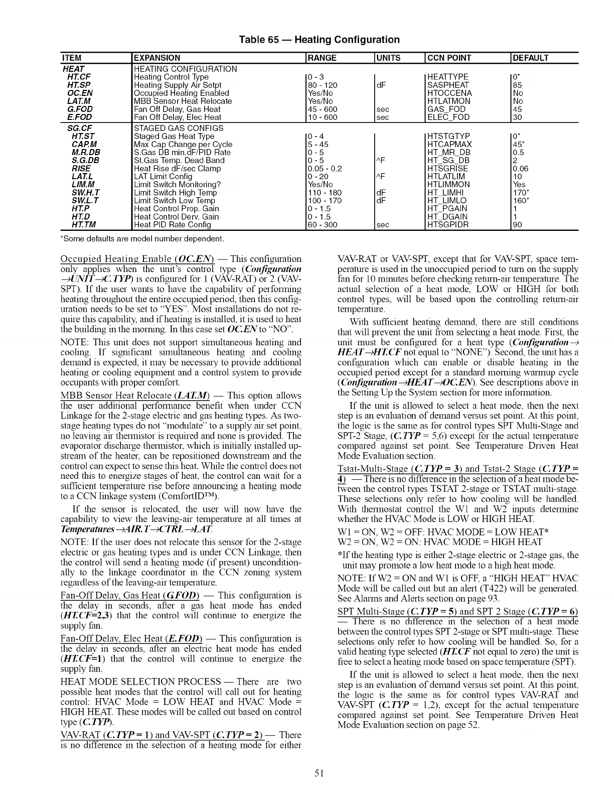
ITEM
HEAT
HT.CF
HT.SP
OC.EN
LAT.M
G.FOD
E.FOD
SG.CF
HT.ST
CAP.M
M.R.DB
S.G.DB
RISE
LAT.L
LIM.M
SW.H.T
SW.L.T
HT.P
HT.D
HT. TM
*Some defaults are
Table 65 -- Heating Configuration
EXPANSION
HEATING CONFIGURATION
Heating Control Type
Heating Supply Air Setpt
Occupied Heating Enabled
MBB Sensor Heat Relocate
Fan Off Delay, Gas Heat
Fan Off Delay, Elec Heat
IRANGE IUNITS
0 - 3 sec
80 - 120 dF
Yes/No
Yes/No
45 - 600
10 - 600 sec
ICON POINT
HEATTYPE
SASPHEAT
HTOCCENA
HTLATMON
GAS FOD
ELEC FOD
STAGED GAS CONFIGS
Staged Gas Heat Type
Max Cap Change per Cycle
S.Gas DB min.dF/PID Rate
St.Gas Temp. Dead Band
Heat Rise dF/sec Clamp
LAT Limit Config
Limit Switch Monitoring?
Limit Switch High Temp
Limit Switch Low Temp
Heat Control Prop. Gain
Heat Control Derv. Gain
Heat PID Rate Config
0-4
5-45
0-5
0-5
0.05 -0.2
0-20
Yes/No
110 - 180
100 - 170
0-1.5
0-1.5
60 - 300
AF
AF
dF
dF
sec
HTSTGTYP
HTCAPMAX
HT MR DB
HT SG DB
HTSGRISE
HTLATLIM
HTLIMMON
HT LIMHI
HT LIMLO
HT PGAIN
HT DGAIN
HT,SGPIDR
model number dependent.
IDEFAULT
45
0*
45*
0.5
2
0.06
10
Yes
170*
160*
11
90
Occupied Heating Enable (OC.EN) -- This configuration
only applies when the unit's control type ((bnfiguration
-gUNIT_C TYP) is configured for 1 (VAV-RAT) or 2 (VAV-
SPT). If the user wants to have the capability of performing
heating throughout the entire occupied period, then this config-
uration needs to be set to "YES". Most installations do not re-
quire this capability, and if heating is installed, it is used to heat
the building in the morning. In this case set OCENto "NO".
NOTE: This unit does not support shnultaneous heating and
cooling. If significant simultaneous heating and cooling
demand is expected, it may be necessary to provide additional
heating or cooling equipment and a control system to provide
occupants with proper comfort.
MBB Sensor Heat Relocate (LAT.M) -- This option allows
the user additional performance benefit when under CCN
Linkage for the 2-stage electric and gas heating types. As two-
stage heating types do not "modulate" to a supply air set point,
no leaving air thermistor is required and none is provided. The
evaporator discharge thermistor, which is initially installed up-
strean of the heater, can be repositioned downstrean and the
control can expect to sense this heat. While the control does not
need this to energize stages of heat, the control can wait for a
sufficient temperature rise before announcing a heating mode
to a CCN linkage system (ComfortID_M).
If the sensor is relocated, the user will now have the
capability to view the leaving-air temperature at all times at
Temper atu res --)AIR. T--c( TRL --cLA T.
NOTE: If the user does not relocate this sensor for the 2-stage
electric or gas heating types and is under CCN Linkage, then
the control will send aheating mode (if present) uncondition-
ally to the linkage coordinator in the CCN zoning system
regardless of the leaving-air temperature.
Fan-Off Delay, Gas Heat (GFOD) -- This configuration is
the delay in seconds, after a gas heat mode has ended
(HT.CF=2,3) that the control will continue to energize the
supply fan.
Fan-Off Delay, Elec Heat (E.FOD) -- This configuration is
the delay in seconds, after an electric heat mode has ended
(HT.CF=I) that the control will continue to energize the
supply fan.
HEAT MODE SELECTION PROCESS -- There are two
possible heat modes that the control will call out for heating
control: HVAC Mode = LOW HEAT and HVAC Mode =
HIGH HEAT. These modes will be called out based on control
type (C. TYP).
VAV-RAT (C. TYP = 1) and VAV-SPT (C TYP = 2) -- There
is no difference in the selection of aheating mode for either
VAV-RAT or VAV-SPT, except that for VAV-SPT, space tem-
perature is used in the unoccupied period to turn on the supply
fan for 10 minutes before checking return-air temperature. The
actual selection of a heat mode, LOW or HIGH for both
control types, will be based upon the controlling return-air
temperature.
With sufficient heating demand, there are still conditions
that will prevent the unit from selecting a heat mode. First, the
unit must be configured for a heat type (Configuration--€
HEAT--+HT.(T not equal to "NONE"). Second, the unit has a
configuration which can enable or disable heating in the
occupied period except for a standard morning warmup cycle
((bnfiguration---_HEAT_OC.EN). See descriptions above in
the Setting Up the System section for more information.
If the unit is allowed to select a heat mode, then the next
step is an evaluation of demand versus set point. At this point,
the logic is the sane as for control types SPT Multi-Stage and
SPT-2 Stage, (C TYP = 5,6) except for the actual temperature
compared against set point. See Temperature Driven Heat
Mode Evaluation section.
Tstat-Multi-Stage ((: TYP = 3) and Tstat-2 Stage ((: TYP =
4) -- There is no difference in the selection of a heat mode be-
tween the control types TSTAT 2-stage or TSTAT multi-stage.
These selections only refer to how cooling will be handled.
With thermostat control the Wl and W2 inputs determine
whether the HVAC Mode is LOW or HIGH HEAT.
Wl = ON, W2 = OFF: HVAC MODE = LOW HEAT*
W2 = ON, W2 = ON: HVAC MODE = HIGH HEAT
*If the heating type is either 2-stage electric or 2-stage gas, the
unit may promote a low heat mode to a high heat mode.
NOTE: If W2 = ON and Wl is OFF, a "HIGH HEAT" HVAC
Mode will be called out but an alert (T422) will be generated.
See Alarms and Alerts section on page 93.
SPT Multi-Stage ((:TYP = 5) and SPT 2 Sta_e ((:TYP = 6)
-- There is no difference in the selection of a heat mode
between the control types SPT 2-stage or SPT multi-stage. These
selections only refer to how cooling will be handled. So, for a
valid heating type selected (HT.(T" not equal to zero) the unit is
free to select a heating mode based on space temperature (SPT).
If the unit is allowed to select a heat mode, then the next
step is an evaluation of demand versus set point. At this point,
the logic is the sane as for control types VAV-RAT and
VAV-SPT (CTYP = 1,2), except for the actual temperature
compared against set point. See Temperature Driven Heat
Mode Evaluation section on page 52.
51
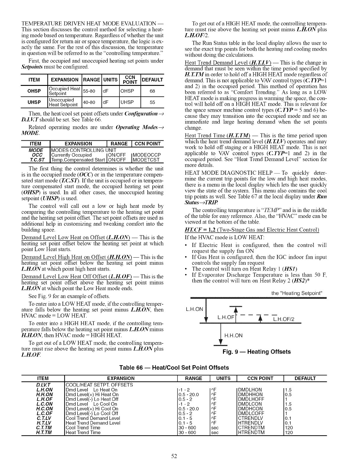
TEMPERATURE DRIVEN HEAT MODE EVALUATION --
This section discusses the control method for selecting a heat-
ing mode based on temperature. Regardless of whether the unit
is configured for return air or space temperature, the logic is ex-
actly the same. For the rest of this discussion, the temperature
in question will be referred to as the "controlling temperature."
First, the occupied and unoccupied heating set points under
Setpoints must be configured.
CCN DEFAULT
ITEM EXPANSION RANGE UNITS POINT
OHSP Occupied Heat
Setpoint 55-80 dF OHSP 68
Unoccupied 40-80 dF UHSP 55
UHSP Heat Setpoint
Then, the heat/cool set point offsets under Configuration
D.LV..Tshould be set. See Table 66.
Related operating modes are under Operating Modes-+
MODE.
ITEM IEXPANSION I RANGE ICON POINT
MODE IMODES CONTROLLING UNIT
OCC ICurrentlyOccupied ION/OFF IMODEOCCP
T.C.ST [Temp.CompensatedStart ION/OFF [MODETCST
The first thing the control determines is whether the unit
is in the occupied mode (O(_) or in the temperature compen-
sated start mode (T.CST). If the unit is occupied or in tempera-
ture compensated start mode, the occupied heating set point
(OHSP) is used. In all other cases, the unoccupied heating
setpoint (UHSP) is used.
The control will call out a low or high heat mode by
comparing the controlling temperature to the heating set point
and the heating set point offset. The set point offsets are used as
additional help in customizing and tweaking comfort into the
building space.
Demand Level Low Heat on Offset (L.H.ON) -- This is the
heating set point offset below the heating set point at which
point Low Heat starts.
Demand Level High Heat on Offset (!-!.!-!.ON) -- This is the
heating set point offset below the heating set point minus
L.H.ONat which point high heat starts.
Demand Level Low Heat Off Offset (L.H.OF)- This is the
heating set point offset above the heating set point minus
L.H.ONat which point the Low Heat mode ends.
See Fig. 9 for an example of offsets.
To enter into a LOW HEAT mode, if the controlling temper-
ature falls below the heating set point minus L.H.ON, then
HVAC mode = LOW HEAT.
To enter into a HIGH HEAT mode, if the controlling tem-
perature falls below the heating set point minus L.H.ONminus
H.H.ON, then HVAC mode = HIGH HEAT.
To get out of a LOW HEAT mode, the controlling tempera-
ture must rise above the heating set point minus L.H.ONplus
L.H.OF
To get out of a HIGH HEAT mode, the controlling tempera-
ture must rise above the heating set point minus L.H.ONplus
L.H.OF/2.
The Run Status table in the local display allows the user to
see the exact trip points for both the heating and cooling modes
without doing the calculations.
Heat Trend Demand Level (tt. T.LV) -- This is the change in
demand that must be seen within the time period specified by
H. r.rMin order to hold off a HIGH HEAT mode regardless of
demand. This is not applicable to VAV control types (C TYP=I
and 2) in the occupied period. This method of operation has
been referred to as "Comfort Trending." As long as a LOW
HEAT mode is making progress in warming the space, the con-
trol will hold off on a HIGH HEAT mode. This is relevant for
the space sensor machine control types (C TYP = 5 and 6) be-
cause they may transition into the occupied mode and see an
immediate and large heating demand when the set points
change.
Heat Trend Time (H. T.TM) -- This is the time period upon
which the heat trend demand level (/-/2.T.LV) operates and may
work to hold off staging or a HIGH HEAT mode. This is not
applicable to VAV control types (CTYP=-I and 2) in the
occupied period. See "Heat Trend Demand Level" section for
more details.
HEAT MODE DIAGNOSTIC HELP -- To quickly deter-
mine the current trip points for the low and high heat modes,
there is a menu in the local display which lets the user quickly
view the state of the system. This menu also contains the cool
trip points as well. See Table 67 atthe local display under Run
Status--c TRIP
The controlling temperature is "TEMP" and is in the middle
of the table for easy reference. Also, the "HVAC" mode can be
viewed at the bottom of the table.
HT.CF =1,2 (Two-Stage Gas and Electric Heat Control)
If the HVAC mode is LOW HEAT:
• If Electric Heat is configured, then the control will
request the supply fan ON
• If Gas Heat is configured, then the IGC indoor fan input
controls the supply fan request
• The control will turn on Heat Relay 1 (HS1)
• If Evaporator Discharge Temperature is less than 50 F,
then the control will turn on Heat Relay 2 (HS2)*
the "Heating Setpoint"
_ H.H.ON
Fig. 9 -- Heating Offsets
ITEM
D.LVT
L.H.ON
H.H.ON
L.H.OF
L.C.ON
H.C.ON
L.C.OF
C.T.LV
H.T.LV
C.T.TM
H.T.TM
Table 66 -- Heat/Cool Set Point Offsets
EXPANSION
COOL/HEAT SETPT. OFFSETS
Dmd Level Lo Heat On
Dmd Level(+) Hi Heat On
Dmd Level(-) Lo Heat Off
Dmd Level Lo Cool On
Dmd Level(+) Hi Cool On
Dmd Level(-) Lo Cool Off
Cool Trend Demand Level
Heat Trend Demand Level
Cool Trend Time
Heat Trend Time
1RANGE JUNITS[ CCNPOINT JDEFAULT
AF DMDLHON
AF DMDHHON
AF DMDLHOFF
AF DMDLCON
AF DMDHCON
AF DMDLCOFF
AF CTRENDLV
AF HTRENDLV
sec CTRENDTM
sec HTRENDTM
-1 - 2
0.5 - 20.0
0.5-2
-1 - 2
0.5 - 20.0
0.5-2
0.1 -5
0.1 -5
30 - 600
30 - 600
1.5
0.5
1
1.5
0.5
1
0.1
0.1
120
120
52
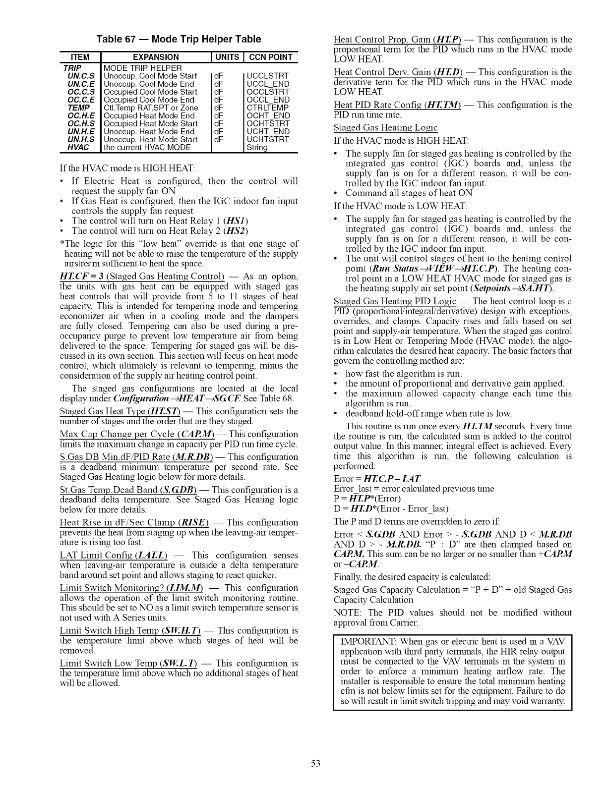
Table 67 -- Mode Trip Helper Table
ITEM
TRIP
UN.C.S
UN.C.E
OC.C.S
OC.C.E
TEMP
OC.H.E
OC.H.S
UN.H.E
UN.H.S
HVAC
EXPANSION
MODE TRIP HELPER
Unoccup, Cool Mode Start
Unoccup, Cool Mode End
Occupied Cool Mode Start
Occupied Cool Mode End
CtI,Temp RAT,SPT or Zone
Occupied Heat Mode End
Occupied Heat Mode Start
Unoccup, Heat Mode End
Unoccup, Heat Mode Start
the current HVAC MODE
I UNITS I CCN POINT
dF
dF
dF
dF
dF
dF
dF
dF
dF
UCCLSTRT
UCCL END
OCCLSTRT
OCCL END
CTRLTEMP
OCHT END
OCHT,STRT
UCHT END
UCHT,STRT
String
If the HVAC mode is HIGH HEAT:
• If Electric Heat is configured, then the control will
request the supply fan ON
• If Gas Heat is configured, then the IGC indoor fan input
controls the supply fan request
• The control will turn on Heat Relay 1 (HS1)
• The control will turn on Heat Relay 2 (HS2)
*The logic for this "low heat" ovemde is that one stage of
heating will not be able to raise the temperature of the supply
airstream sufficient to heat the space.
HT.(T = 3 (Staged Gas Heating Control) -- As an option,
the units with gas heat can be equipped with staged gas
heat controls that will provide from 5 to 11 stages of heat
capacity. This is intended for tempering mode and tempering
economizer air when in a cooling mode and the dampers
are fully closed. Tempering can also be used during a pre-
occupancy purge to prevent low temperature air from being
delivered to the space. Tempering for staged gas will be dis-
cussed in its own section. This section will focus on heat mode
control, which ultimately is relevant to tempering, minus the
consideration of the supply air heating control point.
The staged gas configurations are located at the local
display under (bnfiguration -+HEAT-+SGCF. See Table 68.
Staged Gas Heat Type (HT.ST) -- This configuration sets the
number of stages and the order that are they staged.
Max Cap Change per Cycle (('ARM) -- This configuration
lhnits the maxhnum change in capacity per PID mn time cycle.
S.Gas DB Min.dF/PID Rate (M.R.DB) -- This configuration
is a deadband minimum temperature per second rate. See
Staged Gas Heating logic below for more details.
St.Gas Temp.Dead Band (S.GDB) -- This configuration is a
deadband delta temperature. See Staged Gas Heating logic
below for more details.
Heat Rise in dF/Sec Clamp (RISE) -- This configuration
prevents the heat from staging up when the leaving-air temper-
amre is rising too fast.
LAT Limit Config (EAT.L) -- This configuration senses
when leaving-air temperature is outside a delta temperature
band around set point and allows staging to react quicker.
Limit Switch Monitoring? (LIM.M) -- This configuration
allows the operation of the lhnit switch monitoring routine.
This should be set to NO as a limit switch temperature sensor is
not used with A Series units.
Limit Switch High Temp (SW.H. T) -- This configuration is
the temperature limit above which stages of heat will be
removed.
Limit Switch Low Temp (SW..L. T) -- This configuration is
the temperature limit above which no additional stages of heat
will be allowed.
Heat Control Prop. Gain (HT.P) -- This configuration is the
proportional term for the PID which runs in the HVAC mode
LOW HEAT.
Heat Control Defy. Gain (HT.D) -- This configuration is the
derivative term for the PID which runs in the HVAC mode
LOW HEAT.
Heat PID Rate Config (HT.TM) -- This configuration is the
PID run trine rate.
Staged Gas Heating Logic
If the HVAC mode is HIGH HEAT:
• The supply fan for staged gas heating is controlled by the
integrated gas control (IGC) boards and, unless the
supply fan is on for a different reason, it will be con-
trolled by the IGC indoor fan input.
• Colmnand all stages of heat ON
If the HVAC mode is LOW HEAT:
• The supply fan for staged gas heating is controlled by the
integrated gas control (IGC) boards and, unless the
supply fan is on for a different reason, it will be con-
trolled by the IGC indoor fan input.
• The unit will control stages of heat to the heating control
point (Run Status-+VIEW-+HT.C.P). The heating con-
trol point in a LOW HEAT HVAC mode for staged gas is
the heating supply air set point (Setpoints-+SA.HI).
Staged Gas Heating PID Logic -- The heat control loop is a
PID (proportional/integral/derivative) design with exceptions,
overrides, and clamps. Capacity rises and falls based on set
point and supply-air temperature. When the staged gas control
is in Low Heat or Tempering Mode (HVAC mode), the algo-
rithln calculates the desired heat capacity. The basic factors that
govern the controlling method are:
• how fast the algorithm is run.
• the amount of proportional and derivative gain applied.
• the maximum allowed capacity change each time this
algorithm is run.
• deadband hold-offrange when rate is low.
This routine is run once every HT.TM seconds. Every time
the routine is run, the calculated sum is added to the control
output value. In this manner, integral effect is achieved. Every
time this algorithm is run, the following calculation is
performed:
Error = HT.CP- LAT
Error last = error calculated previous time
P = !aFT.P*(Error)
D = HT.D*(Error - Erro_last)
The P and D terms are ovemdden to zero if:
Error < S.GDB AND Error > - S.GDB AND D < M.R.DB
AND D > - M.R.DB. "P + D" are then clamped based on
('ARM. This sum can be no larger or no smaller than +('ARM
or -('ARM.
Finally, the desired capacity is calculated:
Staged Gas Capacity Calculation = "P + D" + old Staged Gas
Capacity Calculation
NOTE: The PID values should not be modified without
approval from Carrier.
IMPORTANT: When gas or electric heat is used in a VAV
application with third party terminals, the HIR relay output
must be connected to the VAV terminals in the system in
order to enforce a minhnum heating airflow rate. The
installer is responsible to ensure the total minimum heating
cfin is not below lhnits set for the equipment. Failure to do
so will result in lhnit switch tripping and may void warranty.
53
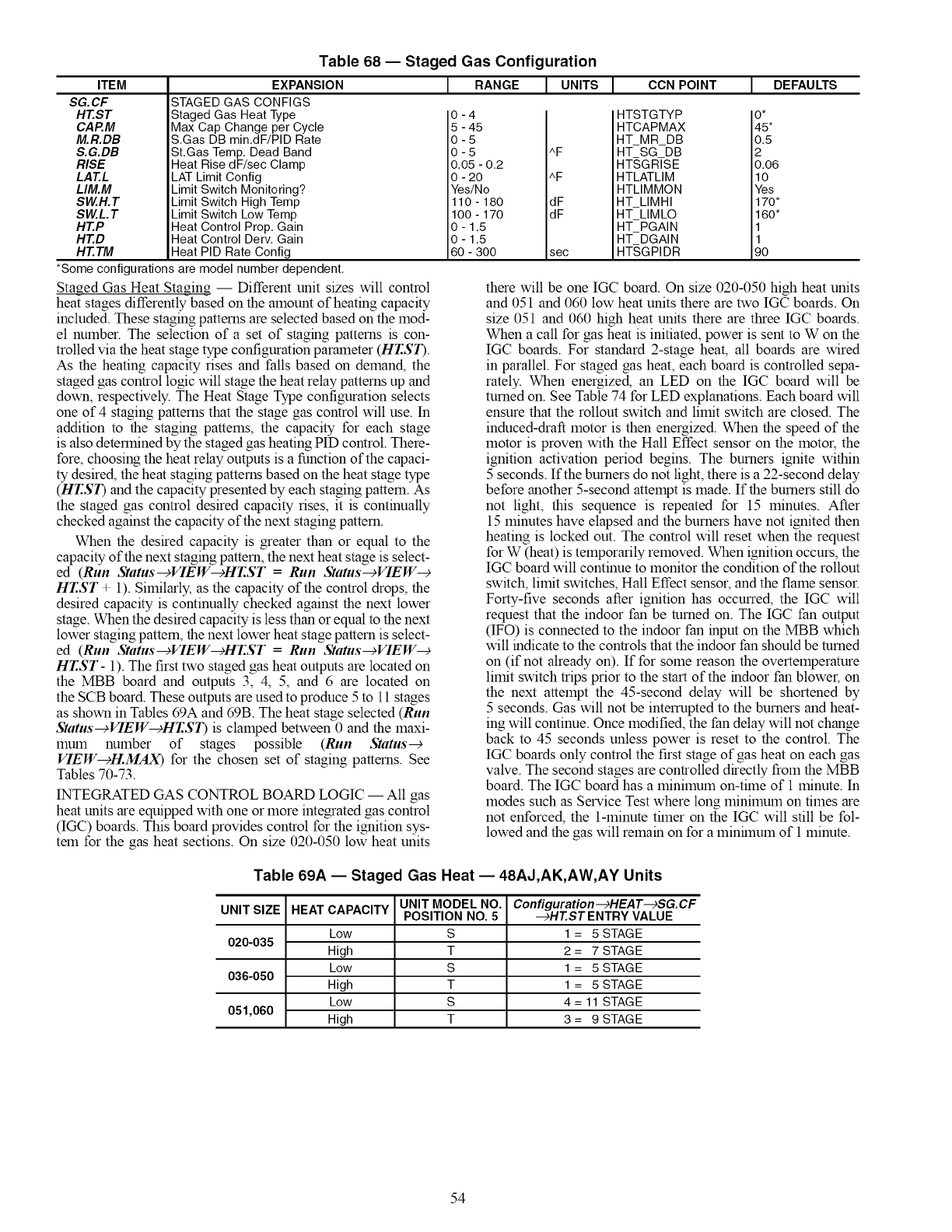
ITEM
SG. CF
HT.ST
CAP.M
M.R.DB
S.G.DB
RISE
LAT.L
LIM.M
SW.H.T
SW.L.T
HT.P
HT.D
HT.TM
Table 68 -- Staged Gas Configuration
EXPANSION
STAGED GAS CONFIGS
Staged Gas Heat Type
Max Cap Change per Cycle
S.Gas DB min.dF/PID Rate
St.Gas Temp. Dead Band
Heat Rise dF/sec Clamp
LAT Limit Config
Limit Switch Monitoring?
Limit Switch High Temp
Limit Switch Low Temp
Heat Control Prop. Gain
Heat Control Derv. Gain
Heat PID Rate Config
JRANGE JUNITS I CCN POINT [DEFAULTS
0-4
5 - 45
0-5
0 - 5 ^F
0.05 - 0.2
0 - 20 ^F
Yes/No
110 - 180 dF
100 - 170 dF
0 - 1,5
0 - 1,5
60 - 300 sec
HTSTGTYP
HTCAPMAX
HT MR DB
HT SG DB
HTSGRISE
HTLATLIM
HTLIMMON
HT LIMHI
HT LIMLO
HT PGAIN
HT DGAIN
HT,SGPIDR
*Some configurations are model number dependent.
O*
45*
0.5
2
0.06
10
Yes
170*
160*
11
90
Staged Gas Heat Staging -- Different unit sizes will control
heat stages differently based on the amount of heating capacity
included. These staging patterns are selected based on the mod-
el number. The selection of a set of staging patterns is con-
trolled via the heat stage type configuration parameter (HT.ST).
As the heating capacity rises and falls based on demand, the
staged gas control logic will stage the heat relay patterns up and
down, respectively. The Heat Stage Type configuration selects
one of 4 staging patterns that the stage gas control will use. In
addition to the staging patterns, the capacity for each stage
is also determined by the staged gas heating PID control. There-
fore, choosing the heat relay outputs is a function of the capaci-
ty desired, the heat staging patterns based on the heat stage type
(HT.ST) and the capacity presented by each staging pattem. As
the staged gas control desired capacity rises, it is continually
checked against the capacity of the next staging pattern.
When the desired capacity is greater than or equal to the
capacity of the next staging pattern, the next heat stage is select-
ed (Run Status-+VIEW-+HT.ST =Run Status-+VIEW-+
HT.ST + 1). Similarly, as the capacity of the control drops, the
desired capacity is continually checked against the next lower
stage. When the desired capacity is less than or equal to the next
lower staging pattem, the next lower heat stage pattern is select-
ed (Run Status-+VIEW-+HT.ST =Run Status-+VIEW-+
HT.ST- 1). The first two staged gas heat outputs are located on
the MBB board and outputs 3, 4, 5, and 6 are located on
the SCB board. These outputs are used to produce 5 to 11 stages
as shown in Tables 69A and 69B. The heat stage selected (Run
Status-+VIEW-+HT.ST) is clamped between 0 and the maxi-
mum number of stages possible (Run Status-+
VIEW-+H.MAX) for the chosen set of staging patterns. See
Tables 70-73.
INTEGRATED GAS CONTROL BOARD LOGIC -- All gas
heat units are equipped with one or more integrated gas control
(IGC) boards. This board provides control for the ignition sys-
tem for the gas heat sections. On size 020-050 low heat units
there will be one IGC board. On size 020-050 high heat units
and 051 and 060 low heat units there are two IGC boards. On
size 051 and 060 high heat units there are three IGC boards.
When a call for gas heat is initiated, power is sent to W on the
IGC boards. For standard 2-stage heat, all boards are wired
in parallel. For staged gas heat, each board is controlled sepa-
rately. When energized, an LED on the IGC board will be
turned on. See Table 74 for LED explanations. Each board will
ensure that the rollont switch and limit switch are closed. The
induced-draft motor is then energized. When the speed of the
motor is proven with the Hall Effect sensor on the motoc the
ignition activation period begins. The burners ignite within
5 seconds. If the burners do not light, there is a 22-second delay
before another 5-second attempt is made. If the burners still do
not light, this sequence is repeated for 15 minutes. After
15 minutes have elapsed and the burners have not ignited then
heating is locked out. The control will reset when the request
for W (heat) is temporarily removed. When ignition occurs, the
IGC board will continue to monitor the condition of the rollout
switch, limit switches, Hall Effect sensor, and the flame sensor.
Forty-five seconds after ignition has occurred, the IGC will
request that the indoor fan be turned on. The IGC fan output
(IFO) is connected to the indoor fan input on the MBB which
will indicate to the controls that the indoor fan should be turned
on (if not already on). If for some reason the overtemperature
limit switch trips prior to the start of the indoor fan blowec on
the next attempt the 45-second delay will be shortened by
5 seconds. Gas will not be interrupted to the burners and heat-
ing will continue. Once modified, the fan delay will not change
back to 45 seconds unless power is reset to the control. The
IGC boards only control the first stage of gas heat on each gas
valve. The second stages are controlled directly from the MBB
board. The IGC board has a minimum on-tflne of 1 minute. In
modes such as Service Test where long minimum on times are
not enforced, the 1-minute tflner on the IGC will still be fol-
lowed and the gas will remain on for a minflnum of 1 minute.
Table 69A -- Staged Gas Heat -- 48AJ,AK,AW,AY Units
UNIT SIZE HEAT CAPACITY UNIT MODEL NO. Configuration-+HEAT-+SG.CF
POSITION NO. 5 -+HT.STENTRY VALUE
Low S 1= 5 STAGE
020-035 High T 2 = 7 STAGE
Low S 1= 5 STAGE
036-050 High T 1 = 5 STAGE
Low S 4 = 11 STAGE
051,060 High T 3 = 9 STAGE
54
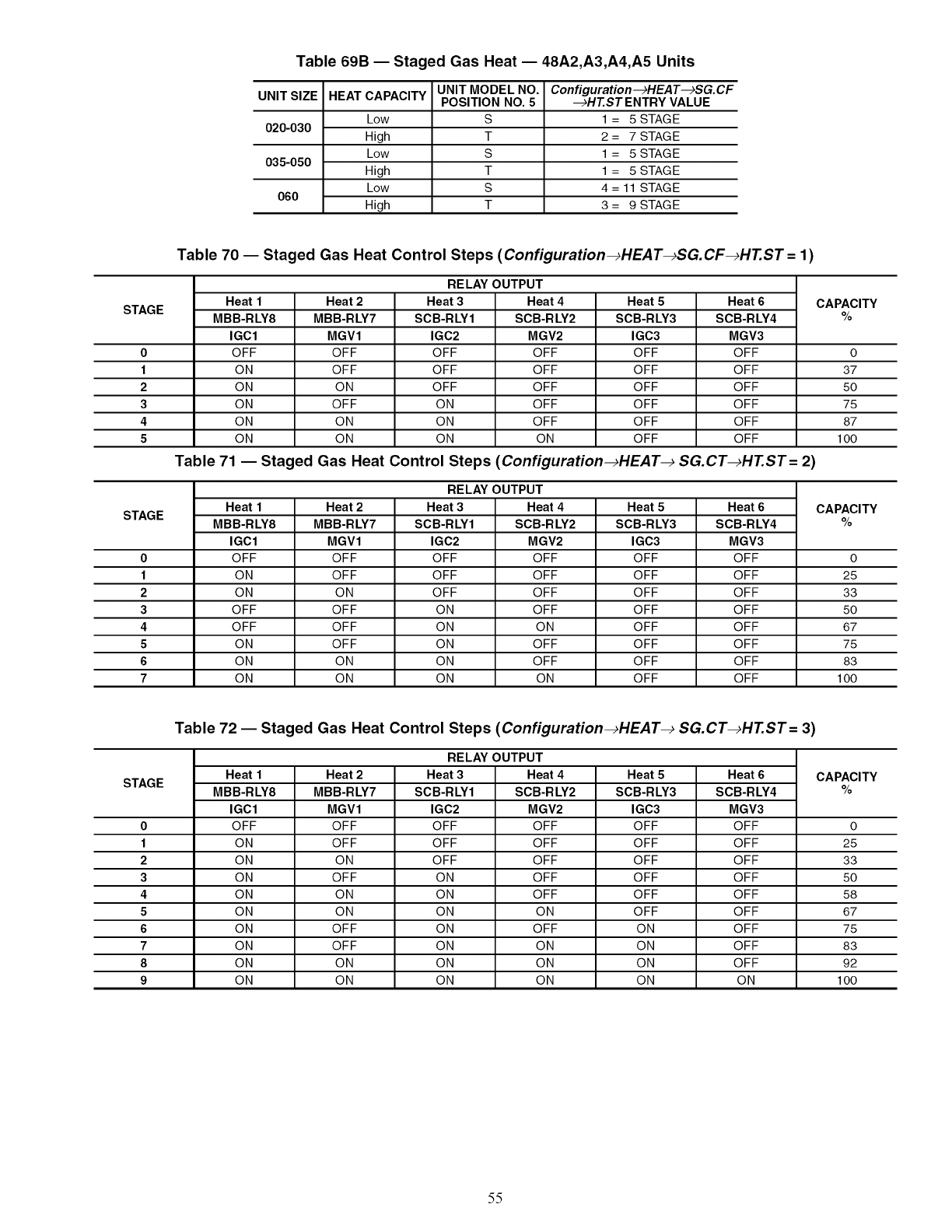
Table 69B -- Staged Gas Heat -- 48A2,A3,A4,A5 Units
UNIT SIZE HEAT CAPACITY UNIT MODEL NO. Configuration--_HEAT-_SG.CF
POSITION NO. 5 --_HT.STENTRY VALUE
Low S 1= 5 STAGE
020-030 High T 2 = 7 STAGE
Low S 1= 5 STAGE
035-050 High T 1 = 5 STAGE
Low S 4 = 11 STAGE
060 High T 3 = 9 STAGE
Table 70 -- Staged Gas Heat Control Steps (Configuration_HEAT_SG.CF_HT.ST = 1)
RELAY OUTPUT
Heat 1 Heat 2 Heat 3 Heat 4 Heat 5 Heat 6 CAPACITY
STAGE MBB-RLY8 MBB-RLY7 SCB-RLY1 SCB-RLY2 SCB-RLY3 SCB-RLY4 %
IGC1 MGV1 IGC2 MGV2 IGC3 MGV3
0OFF OFF OFF OFF OFF OFF 0
1 ON OFF OFF OFF OFF OFF 37
2 ON ON OFF OFF OFF OFF 50
3 ON OFF ON OFF OFF OFF 75
4 ON ON ON OFF OFF OFF 87
5ON ON ON ON OFF OFF 100
Table 71 -- Staged Gas Heat Control Steps (Configuration_HEAT_ SG.CT_HT.ST= 2)
RELAY OUTPUT
Heat 1 Heat 2 Heat 3 Heat 4 Heat 5 Heat 6 CAPACITY
STAGE MBB-RLY8 MBB-RLY7 SCB-RLY1 SCB-RLY2 SCB-RLY3 SCB-RLY4 %
IGC1 MGV1 IGC2 MGV2 IGC3 MGV3
0OFF OFF OFF OFF OFF OFF 0
1 ON OFF OFF OFF OFF OFF 25
2 ON ON OFF OFF OFF OFF 33
3 OFF OFF ON OFF OFF OFF 50
4 OFF OFF ON ON OFF OFF 67
5 ON OFF ON OFF OFF OFF 75
6 ON ON ON OFF OFF OFF 83
7ON ON ON ON OFF OFF 100
Table 72 -- Staged Gas Heat Control Steps (Configuration_HEAT_ SG.CT_HT.ST= 3)
RELAY OUTPUT
Heat 1 Heat 2 Heat 3 Heat 4 Heat 5 Heat 6 CAPACITY
STAGE MBB-RLY8 MBB-RLY7 SCB-RLY1 SCB-RLY2 SCB-RLY3 SCB-RLY4 %
IGC1 MGV1 IGC2 MGV2 IGC3 MGV3
0OFF OFF OFF OFF OFF OFF 0
1 ON OFF OFF OFF OFF OFF 25
2 ON ON OFF OFF OFF OFF 33
3 ON OFF ON OFF OFF OFF 50
4 ON ON ON OFF OFF OFF 58
5 ON ON ON ON OFF OFF 67
6 ON OFF ON OFF ON OFF 75
7 ON OFF ON ON ON OFF 83
8 ON ON ON ON ON OFF 92
9 ON ON ON ON ON ON 100
55
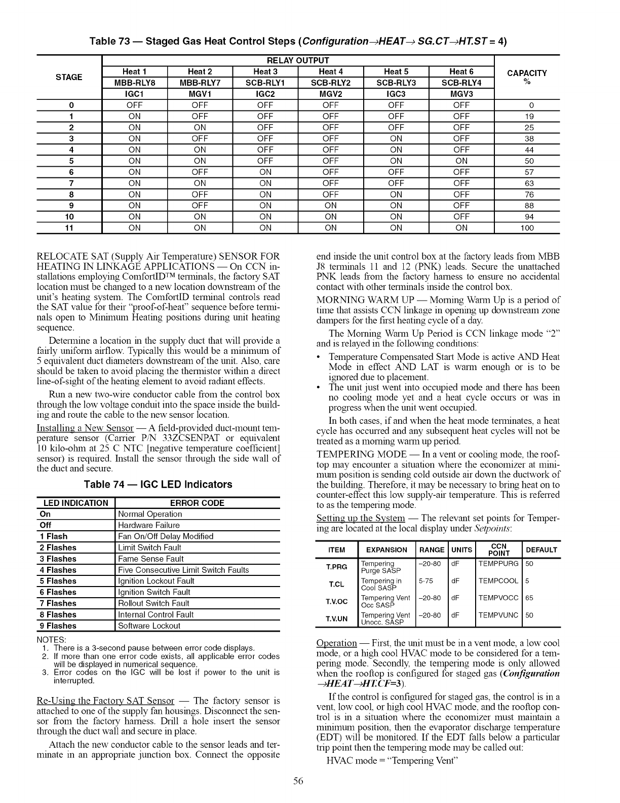
STAGE
Table 73 -- Staged Gas Heat Control Steps (Configuration_HEAT_ SG.CT_HT.ST= 4)
RELAY OUTPUT
Heat 1
MBBIRLY8
IGC1
OFF
ON
ON
ON
ON
ON
ON
ON
ON
ON
ON
ON
Heat 2
MBB-RLY7
MGV1
OFF
OFF
ON
OFF
ON
ON
OFF
ON
OFF
OFF
ON
ON
CAPACITY
%
Heat 3
SCB-RLY1
IGC2
OFF
OFF
OFF
OFF
OFF
OFF
ON
ON
ON
ON
ON
ON
Heat 4
SCB-RLY2
MGV2
OFF
OFF
OFF
OFF
OFF
OFF
OFF
OFF
OFF
ON
ON
ON
Heat 5
SCB-RLY3
IGC3
OFF
OFF
OFF
ON
ON
ON
OFF
OFF
ON
ON
ON
ON
Heat 6
SCB-RLY4
MGV3
OFF
OFF
OFF
OFF
OFF
ON
OFF
OFF
OFF
OFF
OFF
ON
0 0
1 19
2 25
3 38
4 44
550
6 57
7 63
8 76
9 88
10 94
11 100
RELOCATE SAT (Supply Air Temperature) SENSOR FOR
HEATING IN LINKAGE APPLICATIONS -- On CCN in-
stallations employing ComfortID TM terminals, the factory SAT
location must be changed to a new location downstream of the
unit's heating system. The ComfortID terminal controls read
the SAT value for their "proof-of-heat" sequence before termi-
nals open to Minhnum Heating positions during unit heating
sequence.
Determine a location in the supply duct that will provide a
fairly uniform airflow. Typically this would be a minimum of
5 equivalent duct diameters downstream of the unit. Also, care
should be taken to avoid placing the thermistor within a direct
line-of-sight of the heating element to avoid radiant effects.
Run a new two-wire conductor cable from the control box
through the low voltage conduit into the space inside the build-
ing and route the cable to the new sensor location.
Installing a New Sensor -- A field-provided duct-mount tem-
perature sensor (Carrier P/N 33ZCSENPAT or equivalent
10 kilo-otnn at 25 C NTC [negative temperature coefficient]
sensor) is required. Install the sensor through the side wall of
the duct and secure.
Table 74 -- IGC LED Indicators
LED INDICATION
On
Off
1Flash
2 Flashes
3 Flashes
4 Flashes
5 Flashes
6 Flashes
7 Flashes
8 Flashes
9 Flashes
NOTES:
ERROR CODE
Normal Operation
Hardware Failure
Fan On/Off Delay Modified
Limit Switch Fault
Fame Sense Fault
Five Consecutive Limit Switch Faults
Ignition Lockout Fault
Ignition Switch Fault
Rollout Switch Fault
Internal Control Fault
Software Lockout
1. There is a 3-second pause between error code displays.
2. If more than one error code exists, all applicable error codes
will be displayed in numerical sequence.
3. Error codes on the IGC will be lost if power to the unit is
interrupted.
Re-Using the Factory SAT Sensor -- The factory sensor is
attached to one of the supply fan housings. Disconnect the sen-
sor from the factory harness. Drill a hole insert the sensor
through the duct wall and secure in place.
Attach the new conductor cable to the sensor leads and ter-
minate in an appropriate junction box. Connect the opposite
end inside the unit control box at the factory leads from MBB
J8 terminals 11 and 12 (PNK) leads. Secure the unattached
PNK leads from the factory harness to ensure no accidental
contact with other terminals inside the control box.
MORNING WARM UP -- Morning Warm Up is a period of
time that assists CCN linkage in opening up downstream zone
dampers for the first heating cycle of a day.
The Morning Warm Up Period is CCN linkage mode "2"
and is relayed in the following conditions:
• Temperature Compensated Start Mode is active AND Heat
Mode in effect AND LAT is warm enough or is to be
ignored due to placement.
• The unit just went into occupied mode and there has been
no cooling mode yet and a heat cycle occurs or was in
progress when the unit went occupied.
In both cases, if and when the heat mode terminates, a heat
cycle has occurred and any subsequent heat cycles will not be
treated as a morning warm up period.
TEMPERING MODE -- In a vent or cooling mode, the roof-
top may encounter a situation where the economizer at mini-
1hum position is sending cold outside air down the ductwork of
the building. Therefore, it may be necessary to bring heat on to
counter-effect this low supply-air temperature. This is referred
to as the tempering mode.
Setting up the System -- The relevant set points for Temper-
ing are located at the local display under Setpoints:
ITEM
T.PRG
T.CL
T.V.OC
T.V.UN
CON
EXPANSION RANGE UNITS POINT
Tempering -20-80 dF TEMPPURG
Purge SASP
Tempering in 5-75 dF TEMPCOOL
Cool SASP
Tempering Vent -20-80 dF TEMPVOCC
Occ SASP
Tempering Vent -20-80 dF TEMPVUNC
Unocc. SASP
DEFAULT
5O
5
65
5O
Operation -- First, the unit must be in a vent mode, a low cool
mode, or a high cool HVAC mode to be considered for a tem-
pering mode. Secondly, the tempering mode is only allowed
when the rooftop is configured for staged gas (Configuration
--_HEA T--_HT. CF=3 ).
If the control is configured for staged gas, the control is in a
vent, low cool, or high cool HVAC mode, and the rooftop con-
trol is in a situation where the economizer must maintain a
minimum position, then the evaporator discharge temperature
(EDT) will be monitored. If the EDT falls below a particular
trip point then the tempering mode may be called out:
HVAC mode = "Tempering Vent"
56
HVACmode="TemperingLoCool"
HVACmode="TemperingHiCool"
Thedecisionmaking/selectionprocessforthetempering
tripsetpointisasfollows:
• IfanHVACcoolmodeisineffect,thentheventtrippointis
T.(Z.
• If in a pre-occupied purge mode (Operating Modes-+
MODE-+IAQ.P=ON), then the trip point is T.PRG.
• If in an occupied mode (Operating Modes-+MODE
---)IAQ.P=ON), then the trip point is T.V.OC.
• For all other cases, the trip point is T. EUN.
NOTE: The unoccupied economizer free cooling mode does
not qualify as a HVAC cool mode as it is an energy saving
feature and has its own OAT lockout already. The unoccupied
free cooling mode (HVAC mode = Unocc. Free Cool) will
override any unoccupied vent mode from triggering a temper-
ing mode.
If OAT is above the chosen tempering set point, tempering
will not be allowed. Additionally, tempering mode is locked
out if any stages of mechanical cooling are present.
A minimum amount of time must pass before calling out
any tempering mode. In effect, the EDT must fall below
the trip point value -1 ° F continuously for a minrinum of
2 minutes. Also, at the end of a mechanical cooling cycle, there
must be a minrinum 10 minutes of delay allowed before con-
sidering tempering during vent mode in order to allow any
residual cooling to dissipate from the evaporator coil.
If the above conditions are met, the algorittun is free to
select the tempering mode (MODETEMP). If a tempering
mode becomes active, the modulating heat source (staged gas)
will attempt to maintain leaving-air temperature (LAT) at the
tempering set point used to trigger the tempering mode. The
technique for modulation of set point for staged gas and
hydronic heat is the same as in a heat mode. More information
regarding the operation of heating can be referenced in the
Heating Control section.
Recovery from a tempering mode (MODETEMP) will
occur when the EDT rises above the trip point. On any change
in HVACMODE, the tempering routine will re-assess the
tempering set point which may cause the control to continue or
exit tempering mode.
Static Pressure Control -- Variable air volume (VAV)
air-conditioning systems must provide varying amounts of air
to the conditioned space. As air terminals downstream of the
unit modulate their flows, the unit must maintain control over
the duct static pressure in order to accolmnodate the needs of
the terminals and meet the varying combined airflow require-
ment.
A 48/50AK,AY, A3,A5 unit equipped with a duct pressure
control system is provided with a variable frequency drive
(VFD) for the supply fan. The speed of the fan can be con-
trolled directly by the (_l_fortLink TM controls. A transducer is
used to measure duct static pressure. The signal from the trans-
ducer is received by the ECB-2 board and is then used in a PID
control routine that outputs a 4 to 20 mA signal to the VFD.
Generally, only VAV systems utilize static pressure control.
It is required because as the system VAV terminals modulate
closed when less air is required, there must be a means of
controlling airflow from the unit, thereby effectively prevent-
ing overpressurization and its accompanying problems.
The three most fundamental configurations for most appli-
cations are Configuration--cSP--cSRCF, which is the static
pressure control type, Configuration-+SP-+SRS, used to
enable the static pressure sensor, and Configuration-+SP
--+SRSP, the static pressure set point to be maintained.
OPERATION -- On units equipped with a VFD and a proper
static pressure sensor, when SRCF, SRS and SRSP are config-
ured, a PID routine periodically measures the duct static
pressure and calculates the error from set point. This error is
simply the duct static pressure set point minus the measured
duct static pressure. The error becomes the basis for the propor-
tional term of the PID. The routine also calculates the integral
of the error over trine, and the derivative (rate of change) of the
error. A value is calculated as a result of this PID routine, and
this value is then used to create an output signal used to adjust
the VFD to maintain the static pressure set point.
Static pressure reset is the ability to force a lowering of the
static pressure set point through an external control signal.
The unit controls support this in two separate ways, through a 4
to 20 mA signal input wired to the unit's isolator board input
terminals (third party control) or via CCN.
When employing the CCN, this feature uses the colrnnuni-
cations capabilities of VAV systems with ComfortID TM termi-
nals under linkage. The system dynamically determines and
maintains an optrinal duct static pressure set point based on
the actual load conditions in the space. This can result in a
significant reduction in required fan energy by lowering the set
point to only the level required to maintain adequate airflow
throughout the system.
SETTING UP THE SYSTEM -- The options for static
pressure control are found under the Local Display Mode
Configuration-+SP See Table 75.
Failure to correctly configure SRCF and SRFN when
operating in VFD Bypass mode will result in the indoor fan
motor running continuously. Damage to unit could result.
Static Pressure Configuration(SRCF) --This variable is
used to configure the use of (_l_fortLink TM controls for static
pressure control. There are the following options:
-- There will be no static pressure control by
(_nfortLink controls. This setting would be used for a con-
stant volume (CV) application when static pressure control is
not required or for a VAV application if there will be third-party
control of the VFD. In this latter case, a suitable means of con-
trol must be field installed.
Additionally, SR(_T must be set to 0 (None) when a unit is
equipped with optional VFD bypass and is operating in Bypass
mode. Failure to change this configuration in Bypass mode will
result in the indoor fan motor running continuously.
1 (VFD Control) -- This will enable the use of (_n?fortLink
controls for static pressure control via a supply fan VFD.
Static Pressure Fan Control? (SRFN) -- This is automatical-
ly set to Yes when SRCF = 1. When the user would like the 4
to 20 mA output to energize the VFD, as opposed to the fan re-
lay, SRFNmay be set to Yes when SR(_T = 0. When the con-
trol turns the fan ON, the control will send the SRMX value of
the 4 to 20 mA signal to the third party VFD control.
Additionally, SRFN must be set to NO when the unit is
equipped with optional VFD bypass and is operating in Bypass
mode. Failure to change this configuration in bypass mode will
result in the indoor fan motor running continuously.
Static Pressure Sensor (SRS) -- This variable enables the use
of a supply duct static pressure sensor. This must be enabled to
use (_l_fortLink controls for static pressure control. If using a
third-party control for the VFD, this should be disabled.
Static Pressure Low Range (SP.LO) -- This is the minimum
static pressure that the sensor will measure. For most sensors
this will be 0 in. wg. The (_nfortLink controls will map this
value to a 4 mA sensor input.
Static Pressure High Range (SP..H1) -- This is the maximum
static pressure that the sensor will measure. Colrnnonly this
will be 5 m. wg. The (_n_fortLink controls will map this value
to a 20 mA sensor input.
57
Static Pressure Set Point (SRSP) -- This is the static pres-
sure control point. It is the point against which the
(_l_fortLink controls compare the actual measured supply
duct pressure for determination of the error that is used for PID
control. Generally one would set SRSP to the minimum value
necessary for proper operation of air terminals in the condi-
tioned space at all load conditions. Too high of a value will
cause unnecessary fan motor power consumption at part-load
conditions and/or noise problems. Too low a value will result in
insufficient airflow.
VFD Minhnum Speed (SRMN) -- This is the minhnum speed
for the supply fan VFD. Typically the value is chosen to main-
tain a minhnum level of ventilation.
NOTE: Most VFDs have a built-in minimum speed adjustment
which must be configured for 0% when using (_nfortLink
controls for static pressure control.
VFD Maximum Speed (SRMX) -- This is the maximum
speed for the supply fan VFD. This is usually set to 100%.
VFD Fire Speed Override (SRFS) -- This is the speed that
the supply fan VFD will use during the pressurization, evacua-
tion and purge fire modes. This is usually set to 100%.
Static Pressure Reset Configuration (SRRS) -- This option
is used to configure the static pressure reset function. When
SRRS = 0, there is no static pressure reset via an analog input.
If the outdoor air quality sensor is not configured (Configura-
tion---_IAQ---_IAQ. (T_OQ.A. C = 0), then it is possible to use
the outdoor air quality sensor location on the CEM board to
perform static pressure reset via an external 4 to 20 mA input.
Configuring SRRS = 1 provides static pressure reset based
on this CEM 4 to 20 mA input and ranged from 0 to 3 in. wg.
Wire the input to the CEM using TB6-11 and 12. When SRRS
= 2, there is static pressure reset based on RAT and defined by
SRRTand SRLM. WhenSRRS = 3, there is static pressure re-
set based on SPT and defined by SRRTand SRLM.
Setting SRRS to 1, 2 or 3 will give the user the ability to re-
set from 0 to 3 in. wg of static pressure. The reset will apply to
the supply static pressure set point. The static pressure reset
function will only act to reduce the static pressure control point.
As an example, the static pressure reset input is measuring
6 mA, and is therefore resetting 2 mA (6 mA - 4 mA) of its
16 mA control range. The 4 to 20 mA range corresponds
directly to the 0 to 3 in. wg of reset. Therefore 2 mA reset is
2/16 * 3 in. wg = 0.375 in. wg of reset. If the static pressure set
point (SRSP) = 1.5 in. wg, then the static pressure control point
for the system will be reset to 1.5 - 0.375 = 1.125 in. wg.
When SRRS = 4, the static pressure reset function acts to
provide direct VFD speed control where 4 mA = 0% speed and
20 mA = 100% (SRMN and SRMX will override). Note that
SRCF must be set to 1 (VFD Control), prior to configuring
SRRS = 4. Failure to do so could result in damage to ductwork
due to overpressurization. This is the recolmnended approach
if a third party wishes to control the variable speed supply fan.
In effect, this represents a speed control signal "pass through"
under normal operating circumstances. The (_l_fortLink con-
trol system ovemdes the third party signal for critical operation
situations, most notably smoke and fire control.
Static Pressure Reset Ratio (SRRT) -- This option defines
the reset ratio in terms of static pressure versus temperature.
The reset ratio determines how much is the static pressure
reduced for every degree below set point for RAT or SPT.
Static Pressure Reset Limit (SRLM) -- This option defines
the maximum amount of static pressure reset that is allowed.
This is sometimes called a "clalnp."
NOTE: Resetting static pressure via RAT and SPT is prhnarily
a constant volume application which utilizes a VFD. The rea-
soning is that there is significant energy savings in slowing
down a supply fan as opposed to running full speed with
supply air reset. Maintaining the supply air set point and
slowing down the fan has the additional benefit of working
around dehumidification concerns.
Static Pressure Reset Economizer Position (SRE(_) -- This
option effectively resets ECONOM1N to fully occupied venti-
lation position, to account for the drop in static pressure during
static pressure reset control. The static pressure reset for the
calculation cannot be larger than the supply air static set point
(SPSP).
The calculation is as follows:
(Static Pressure Reset/SPSP) x (ECONOSPR- ECONOM1N)
As an example, the static pressure set point (SPSP) =
1.5 in. wg. The current static pressure reset is set to 0.5 in. wg.
The settings for ECONOSPR = 50% and ECONOM1N = 20%.
Table 75 -- Static Pressure Control Configuration
ITEM EXPANSION RANGE UNITS CCN POINT DEFAULT
SP SUPPLY STATIC PRESS.CFG.
SP.CF Static Pres. VFD Control? 0, 1 STATICFG 0*
SP.FN Static Pres. Fan Control? Yes/No STATPFAN Yes*
SP.S Static Pressure Sensor Enable/Disable SPSENS Disable*
SP.LO Static Press. Low Range -10 - 0 in. W.C. SP_LOW 0
SP.HI Static Press. High Range 0 - 10 in. W.C. SP_HIGH 5
SP.SP Static Pressure Setpoint 0 - 5 in. W.C. SPSP 1.5
SP.MN VFD Minimum Speed 0 - 100 % STATPMIN 20
SP.MX VFD Maximum Speed 0 - 100 % STATPMAX 100
SP.FS VFD Fire Speed Override 0 - 100 % STATPFSO 100
SP.RS Stat. Pres. Reset Config 0 - 4 SPRSTCFG 0
SP.RT SP Reset Ratio ("/dF) 0 - 2.00 SPRRATIO 0.2
SP.LM SP Reset Limit in iwc (") 0 - 2.00 SPRLIMIT 0.75
SP.EC SP Reset Econo.Position 0 - 100 % ECONOSPR 5
S.PID STAT.PRESS.PID CONFIGS
SP.TM Static Press. PID Run Rate 1 - 200 sec SPIDRATE 2
SP.P Static Press. Prop. Gain 0 - 100 STATP_PG 20
SP.I Static Press. Intg. Gain 0 -50 STATP_IG 2
SP.D Static Press. Derv. Gain 0 - 50 STATP_DG 0
SP.SG Static Press. System Gain 0 - 50 STATP_SG 1.0
*Some defaults are model number dependent.
58
Therefore, the amount to add to the economizer's
ECONOMIN configuration is: (0.5/1.5) x (50-20) = 10%. In
effect, for the positioning of the economizer, ECONOMIN
would now be replaced by ECONOMIN + 10%.
Static Pressure PID Config (S.PID) -- Static pressure PID
configuration can be accessed under this heading in the Con-
figuration--+SP submenu. Under most operating conditions the
control PID factors will not require any adjustment and the
factory defaults should be used. If persistent static pressure
fluctuations are detected, small changes to these factors ]nay
improve performance. Decreasing the factors generally reduce
the responsiveness of the control loop, while increasing the
factors increase its responsiveness. Note the existing settings
before making changes, and seek technical assistance from
Carrier before making significant changes to these factors.
Static Pressure PID Run Rate (S.PID--cSRTM) This is the
number of seconds between duct static pressure readings taken
by the (_n_fortLink TM PID routine.
Static Pressure Plvportional Gain (S.PID--cSRP) This is
the proportional gain for the static pressure control PID control
loop.
Static Pressure Integlwl Gain (S.PID--)SRI) This is the
integral gain for the static pressure control PID control loop.
Static Pressure Derivative Gain (S.PID-+SRD) This is the
derivative gain for the static pressure control PID control loop.
Static Pressure System Gain (S.PID--)SRSG) -- This is the
system gain for the static pressure control PID control loop.
STATIC PRESSURE RESET OPERATION --The
(_nfortLink controls support the use of static pressure reset.
The Linkage Master terminal monitors the primary air damper
position of all the terminals in the system (done through LINK-
AGE with the new ComfortID TM air terminals).
The Linkage Master then calculates the amount of supply
static pressure reduction necessary to cause the most open
damper in the system to open more than the minimum value
(60%) but not more than the maximum value (90% or negligi-
ble static pressure drop). This is a dynamic calculation, which
occurs every two minutes when ever the system is operating.
The calculation ensures that the supply static pressure is always
enough to supply the required airflow at the worst case termi-
nal but never more than necessary, so that the prhnary air
dampers do not have to operate with an excessive pressure
drop (more than required to maintain the airflow set point of
each individual terminal in the system).
As the system operates, if the most open damper opens
more than 90%, the system recalculates the pressure reduction
variable and the value is reduced. Because the reset value is
subtracted from the controlling set point at the equipment, the
pressure set point increases and the primary-air dampers close
a little (to less than 90%). If the most open damper closes to
less than 60%, the system recalculates the pressure reduction
variable and the value is increased. This results in a decrease in
the controlling set point at the equipment, which causes the
primary-air dampers to open a little more (to greater than 60%).
The rooftop unit has the static pressure set point
progralrnned into the CCN control. This is the maximum set
point that could ever be achieved under any condition. To
simplify the installation and connnissioning process for the
field, this system control is designed so that the installer only
needs to enter a lnaxilnum duct design pressure or lnaximum
equipment pressure, whichever is less. There is no longer a
need to calculate the worst case pressure drop at design condi-
tions and then hope that some intermediate condition does not
require a higher supply static pressure to meet the load
conditions. For example, a system design requirement ]nay be
1.2 in. wg, the equipment ]nay be capable of providing
3.0 in. wg and the supply duct is designed for 5.0 in. wg. In this
case, the installer could enter 3.0 in. wg as the supply static
pressure set point and allow the air terminal system to dynami-
cally adjust the supply duct static pressure set point as required.
The system will deter]nine the actual set point required de-
livering the required airflow at every terminal under the current
load conditions. The set point will always be the lowest value
under the given conditions. As the conditions and airflow set
points at each terminal change throughout the operating period,
the equipment static pressure set point will also change.
The CCN system must have access to a CCN variable
(SPRESET which is part of the equipment controller). In the
algorithin for static pressure control, the SPRESET value is
always subtracted from the configured static pressure set point
by the equipment controller. The SPRESET variable is always
checked to be a positive value or zero only (negative values are
limited to zero). The result of the subtraction of the SPRESET
variable from the configured set point is limited so that it
cannot be less than zero. The result is that the system will
dynamically deter]nine the required duct static pressure based
on the actual load conditions currently in the space. This elimi-
nates the need to calculate the design supply static pressure set
point. This also saves the energy difference between the design
static pressure set point and the required static pressure.
Third Party 4 to 20 mA Input -- It is also possible to perform
static pressure reset via an external 4 to 20 mA signal connect-
ed to the CEM board where 4 mA corresponds to 0 m. wg of
reset and 20 mA corresponds to 3 in. wg of reset. The static
pressure 4 to 20 mA input shares the same input as the analog
OAQ sensor. Therefore, both sensors cannot be used at the
same thne. To enable the static pressure reset 4 to 20 mA sen-
sor, set (Configuration---_SP---_SRRS) to Enabled.
RELATED POINTS -- These points represent static pressure
control and static pressure reset inputs and outputs. See Table 76.
Static Pressure mA (SR_ -- This variable reflects the value
pressure sensor signal received by the
controls. The value ]nay be helpful in trouble-
of the static
(_nfortLink TM
shooting.
Static Pressure mA Trim (SRM.T) -- This input allows a
modest amount of trhn to the 4 to 20 mA static pressure trans-
ducer signal, and can be used to calibrate a transducer.
Static Pressure Reset mA (SRR.M) -- This input reflects the
value of a 4 to 20 mA static pressure reset signal applied to
TB6 terminals 11 and 12 on the CEM board, from a third party
control system.
Static Pressure Reset (SRRS) -- This variable reflects the
value of a static pressure reset signal applied from a CCN sys-
tem. The means of applying this reset is by forcing the value of
the variable SPRESET through CCN.
Supply Fan VFD Speed (S. VFD) -- This output can be used
to check on the actual speed of the VFD. This ]nay be helpful
in some cases for troubleshooting.
Fan Status Monitoring
GENERAL- The A Series (_n_fortLink controls offer the
capability to detect a failed supply fan through either a duct
static pressure transducer or an accessory discrete switch. The
fan stares switch is an accessory that allows for the monitoring
of a discrete switch, which trips above a differential pressure
drop across the supply fan. For any unit with a factory-installed
duct static pressure sensoc it is possible to measure duct
pressure rise directly, which removes the need for a differential
switch. All 48/50AK,AW, A3,A5 units with a factory-installed
supply fan VFD will have the duct static pressure sensor as
standard.
SETTING UP THE SYSTEM -- The fan stares momtoring
configurations are located in Configuration--gUNIr. See
Table 77.
59
Table 76 -- Static Pressure Reset Related Points
ITEM EXPANSION RANGE UNITS CCN POINT DEFAULT
Inputs
-_ 4-20 -_ SP.M Static Pressure mA 4-20 mA SP_MA
-_ 4-20 -_ SP.M.T Static Pressure mA Trim -2,0 - +2,0 mA SPMATRIM
-_ 4-20 -_SP.R.M Static Pressure Reset mA 4-20 mA SPRST_MA 0,0
-_ RSET -_SP.RS Static Pressure Reset 0,0-3,0 in, wg SPRESET 0,0
Outputs
-_ Fans -_ S.VFD Supply Fan VFD Speed 0-100 % SFAN_VFD
Table 77 -- Fan Status Monitoring Configuration
ITEM EXPANSION RANGE CCN POINT
SFS.S Fan Fail Shuts Down Unit Yes/No SFS_SHUT
SFS.M Fan Stat Monitoring Type 0 - 2 SFS_MON
Fan Stat Monitoring Type (SFS.M) -- This configuration se-
lects the type of fan stares monitoring to be performed.
0 - NONE -- No switch or monitoring
1 - SWITCH --Use of the fan status switch
2 - SP RISE -- Monitoring of the supply duct pressure.
Fan Fail Shuts Down Unit (SFS.S) -- This configuration
will configure the unit to shut down on a supply fan status fail
or shnply alert the condition and continue to run. When config-
ured to YES, the control will shut down the unit if supply fan
stares monitoring fails and the control will also send out an
alarm. If set to NO, the control will not shut down the unit if
supply fan status monitoring fails but will send out an alert.
SUPPLY FAN STATUS MONITORING LOGIC -- Regard-
less of whether the user is monitoring a discrete switch or is
monitoring static pressure, the thning for both methods are the
same and rely upon the configuration of static pressure control.
The configuration that determines static pressure control is
Configurafion--)SP--)SRCF. If this configuration is set to 0
(none), a fan failure condition must wait 60 continuous seconds
before taking action. If this configuration is 1 (VFD), a fan fail-
ure condition must wait 3 continuous minutes before taking
action.
If the unit is configured to monitor a fan stares switch
(SFS.M = 1), and if the supply fan colmnanded state does not
match the supply fan status switch for 3 continuous minutes,
then a fan status failure has occurred.
If the unit is configured for supply duct pressure monitoring
(SFS.M = 2), then
• If the supply fan is requested ON and the static pressure
reading is not greater than 0.2 in. wg for 3 continuous
minutes, a fan failure has occurred.
• If the supply fan is requested OFF and the static pressure
reading is not less than 0.2 in. wg for 3 continuous min-
utes, a fan failure has occurred.
Dirty Filter Switch EThe unit can be equipped with a
field-installed accessory dirty filter switch. The switch is located
in the filter section. If a dirty filter switch is not installed, the
switch input is configured to read "clean" all the time.
To enable the sensor for dirty filter monitoring set
Configuration--+UNIT--+SENS--+FLT.S to ENABLE. The
state of the filter status switch can be read at Inputs_GEN.I-€
FLT.S. See Table 78.
Table 78 -- Dirty Filter Switch Points
CCN
ITEM EXPANSION RANGE POINT
Configuration-_UNIT Filter Enable/ FLTS ENA
-_SENS-_FLT.S Stat.Sw.Enabled ? Disable
Inputs-_GEN.I Filter Status Input DRTY/CLN FLTS
-+FLT.S
Monitoring of the filter stares switch is disabled in the
Service Test mode and when the supply fan is not colmnanded
on. If the fan is on and the unit is not in a test mode and the
filter status switch reads "dirty" for 2 continuous minutes, an
alert is generated. Recovery from this alert is done through a
clearing of all alarms or after cleaning the filter and the switch
reads "clean" for 30 seconds.
NOTE: The filter switch should be adjusted to allow for the
operating cfm and the type of filter. Refer to the accessory
installation instructions for information on adjusting the switch.
Economizer EThe economizer control is used to manage
the outside and return air dampers of the unit to provide venti-
lation air as well as free cooling based on several configuration
options. This section contains a description of the economizer
and its ability to provide free cooling. See the section on Indoor
Air Quality Control on page 67 for more information on setting
up and using the economizer to perform demand controlled
ventilation (DCV). See the Third Party Control section for a
description on how to take over the operation of the economiz-
er through external control.
The economizer system also permits this unit to perform
smoke control functions based on external control switch
inputs. Refer to the Smoke Control Modes section for detailed
discussions.
Economizer control can be based on automatic control
algoritlnns using unit-based set points and sensor inputs. This
economizer control system can also be managed through exter-
nal logic systems.
The economizer system is a factory-installed option. This
unit can also have the following devices installed to enhance
economizer control:
• Outside air humidity sensor
• Return air humidity sensor
NOTE: All these options require the controls expansion mod-
ule (CEM).
SETTING UP THE SYSTEM -- The economizer configura-
tion options are under the Local Display Mode Configuration
--_ECON. See Table 79.
Economizer Installed? (ECEN) -- If an economizer is not
installed or is to be completely disabled then the configuration
option ECEN should be set to No. Otherwise in the case of an
installed economizer, this value must be set to Yes.
Economizer Minimum Position (ECMN) -- The configura-
tion option ECMN is the economizer lninimum position. See
the section on indoor air quality for further information on how
to reset the economizer further to gain energy savings and to
more carefully monitor IAQ problems.
Economizer Maximum Position (ECMX) -- The upper lim-
it of the economizer may be lhnited by setting ECMX This
value defaults to 98% to avoid problems associated with slight
changes in the economizer damper's end stop over time. Typi-
cally this will not need to be adjusted.
Economizer Trim for Sum Z? (E. TRM) -- Sum Z is the
adaptive cooling control algorittun used for multiple stages
of mechanical cooling capacity. The configuration option,
E. TRM is typically set to Yes, and allows the economizer to
6O
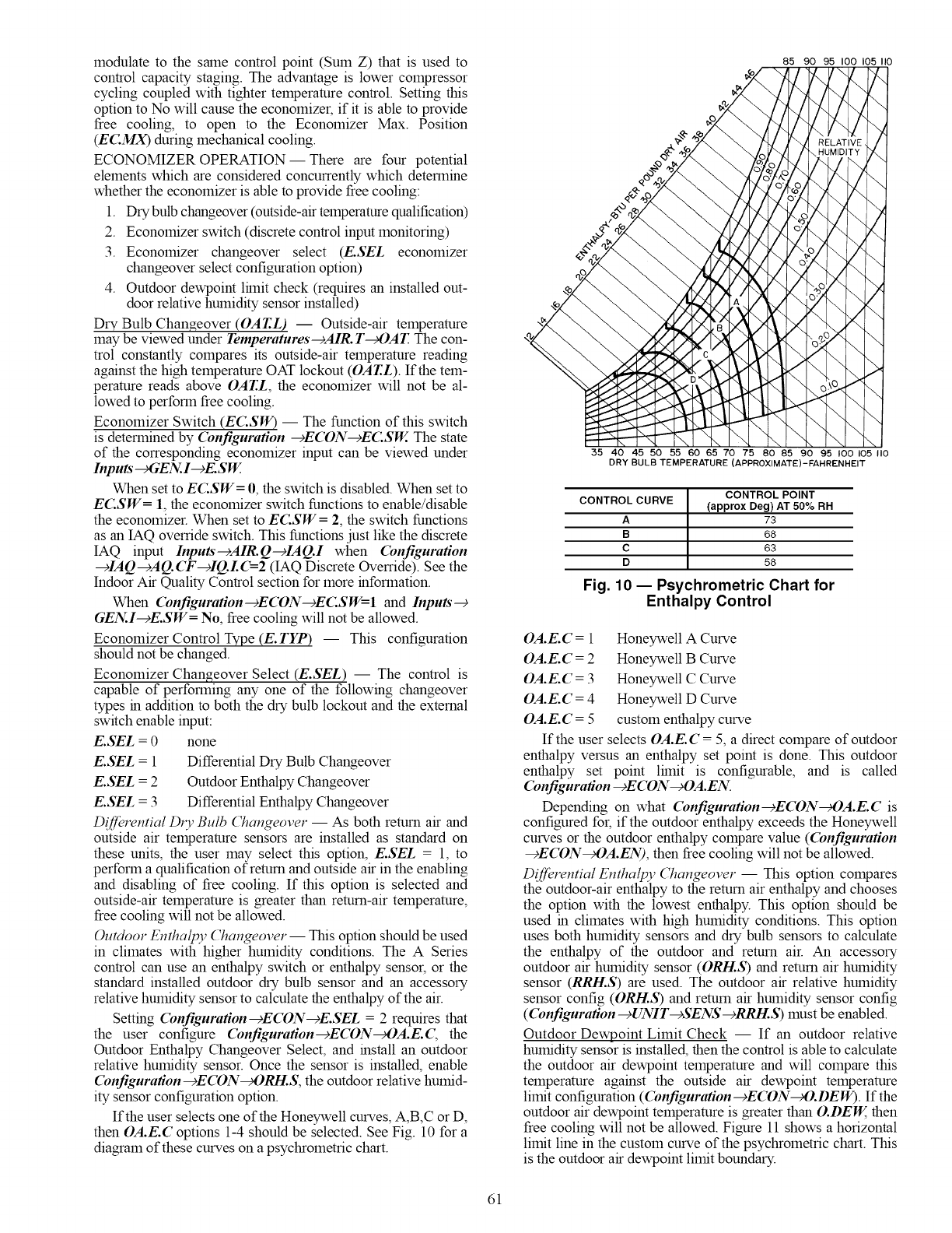
modulateto thesamecontrolpoint(SumZ)thatisusedto
controlcapacitystaging.Theadvantageislowercompressor
cyclingcoupledwithtightertemperaturecontrol.Settingthis
optiontoNowillcausetheeconomizer,if it isabletoprovide
freecooling,to opento theEconomizerMax.Position
(ECMX)duringmechanicalcooling.
ECONOMIZEROPERATION-- Therearefourpotential
elementswhichareconsideredconcurrentlywhichdetermine
whethertheeconomizerisabletoprovidefreecooling:
1. Drybulbchangeover(outside-airtemperaturequalification)
2. Economizerswitch(discretecontrolinputmonitoring)
3. Economizerchangeoverselect(E.SELeconomizer
changeoverselectconfigurationoption)
4. Outdoordewpointlhnitcheck(requiresaninstalledout-
doorrelativehumiditysensorinstalled)
Dry Bulb Changeover (OAT.L) -- Outside-air temperature
may be viewed under remperatures---)AIR. T_OAT. The con-
trol constantly compares its outside-air temperature reading
against the high temperature OAT lockout (OAT.L). If the tem-
perature reads above OAT.L, the economizer will not be al-
lowed to perform free cooling.
Economizer Switch (ECSW) -- The function of this switch
is determined by (bnfiguration -+ECON--cECSW. The state
of the corresponding economizer input can be viewed under
Inputs"_GEN.. I--cE.SW.
When set to EC.SW= 0, the switch is disabled. When set to
EC.SW= 1, the economizer switch functions to enable/disable
the economizer. When set to EC.SW = 2, the switch functions
as an IAQ override switch. This functions just like the discrete
IAQ input Inputs--)AIR.Q--clAQ.I when (bnfiguration
--€IAQ---)AQ. CF--clQ.L 4--2 (IAQ Discrete Override). See the
Indoor Air Quality Control section for more information.
When (bnfiguration-cE(DN-cEC.SW=l and Inputs--€
GEN..I--_E.SW= No, free cooling will not be allowed.
Economizer Control Type (E.TYP) -- This configuration
should not be changed.
Economizer Changeover Select (E.SEL) -- The control is
capable of performing any one of the following changeover
types in addition to both the dry bulb lockout and the external
switch enable input:
E.SEL = 0 none
E.SEL = 1 Differential Dry Bulb Changeover
E.SEL = 2 Outdoor Enthalpy Changeover
E.SEL = 3 Differential Enthalpy Changeover
Differential D1T Bulb Changeover -- As both return air and
outside air temperature sensors are installed as standard on
these units, the user may select this option, E.SEL = 1, to
perform a qualification of return and outside air in the enabling
and disabling of free cooling. If this option is selected and
outside-air temperature is greater than return-air temperature,
free cooling will not be allowed.
Outdoor Enthalpy Changeover-- This option should be used
in climates with higher humidity conditions. The A Series
control can use an enthalpy switch or enthalpy sensor, or the
standard installed outdoor dry bulb sensor and an accessory
relative humidity sensor to calculate the enthalpy of the air.
Setting Configuration-+ECON-+E.SEL = 2 requires that
the user configure (bnfiguration-cECON_OA.E.(; the
Outdoor Enthalpy Changeover Select, and install an outdoor
relative humidity sensor. Once the sensor is installed, enable
(bnfiguration--cECON_ORH.S, the outdoor relative humid-
ity sensor configuration option.
If the user selects one of the Honeywell curves, A,B,C or D,
then OA.E.C options 1-4 should be selected. See Fig. 10 for a
diagram of these curves on a psychrometric chart.
85 90 95 I00 105 I10
35 40 45 50 55 60 65 70 7'5 80 85 90 95 100 105 II0
DRY BULB TEMPERATURE (APPROXIMATE)-FAHRENHEIT
CONTROL POINT
CONTROL CURVE (approx Deg) AT 50% RH
A 73
B 68
C 63
D 58
Fig. 10 -- Psychrometric Chart for
Enthalpy Control
OA.E.C = 1 Honeywell A Curve
OA.E.C = 2 Honeywell B Curve
OA.E.C = 3 Honeywell C Curve
OA.E.C = 4 Honeywell D Curve
OA.E.C = 5 custom enthalpy curve
If the user selects OA.E. C = 5, a direct compare of outdoor
enthalpy versus an enthalpy set point is done. This outdoor
enthalpy set point lhnit is configurable, and is called
(bnfiguration -¢ECON-cOA.EN.
Depending on what (bnfiguration--cECON_OA.E.C is
configured for, if the outdoor enthalpy exceeds the Honeywell
curves or the outdoor enthalpy compare value ((bnfiguration
-+ECON_OA.EN), then free cooling will not be allowed.
Diff'erential Enthalpy Changeover -- This option compares
the outdoor-air enthalpy to the return air enthalpy and chooses
the option with the lowest enthalpy. This option should be
used in climates with high humidity conditions. This option
uses both humidity sensors and dry bulb sensors to calculate
the enthalpy of the outdoor and return air. An accessory
outdoor air humidity sensor (OR!-LS) and return air humidity
sensor (RRH.S) are used. The outdoor air relative humidity
sensor config (OR!-LS) and return air humidity sensor config
(Configuration--cUNIT--cSENS--cRRI-L.S) must be enabled.
Outdoor Dewpoint Limit Check -- If an outdoor relative
humidity sensor is installed, then the control is able to calculate
the outdoor air dewpoint temperature and will compare this
temperature against the outside air dewpoint temperature
limit configuration (Configuration--cECON--_,O.DEW). If the
outdoor air dewpoint temperature is greater than O.DEW, then
free cooling will not be allowed. Figure 11 shows a horizontal
limit line in the custom curve of the psychrometric chart. This
is the outdoor air dewpoint limit boundary.
61
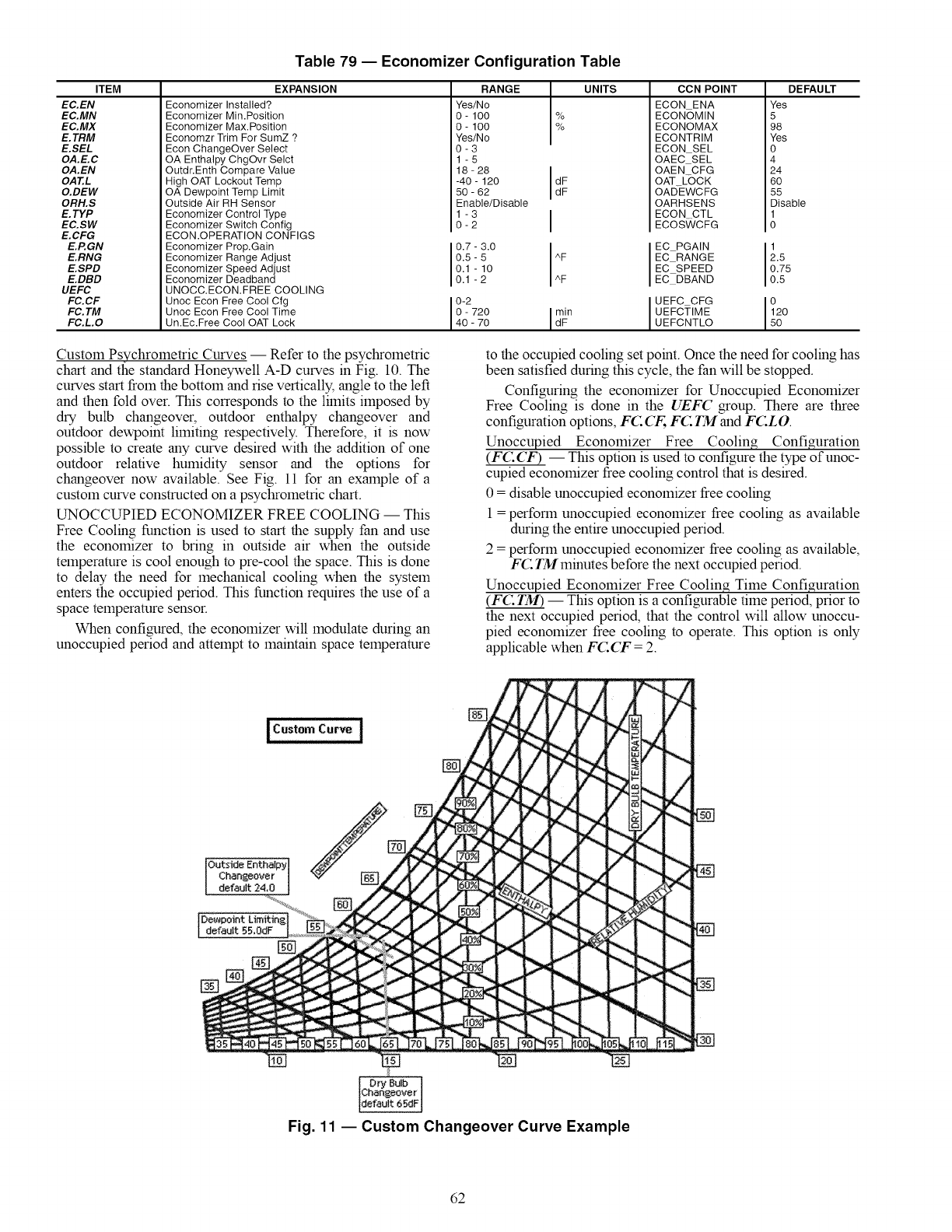
ITEM
EC.EN
EC.MN
EC.MX
E.TRM
E. SEL
OA.E.C
OA.EN
OAT.L
O.DEW
ORH.S
E. TYP
EC.SW
E. CFG
E.P.GN
E.RNG
E.SPD
E.DBD
UEFC
FC.CF
FC. TM
FC.L.O
Table 79 -- Economizer Configuration Table
EXPANSION
Economizer Installed?
Economizer Min.Position
Economizer Max.Position
Economzr Trim For SumZ ?
Econ ChangeOver Select
OA Enthalpy ChgOvr Selct
Outdr.Enth Compare Value
High OAT Lockout Temp
OA Dewpoint Temp Limit
Outside Air RH Sensor
Economizer Control Type
Economizer Switch Config
ECON.OPERATION CONFIGS
Economizer Prop.Gain
Economizer Range Adjust
Economizer Speed Adjust
Economizer Deadband
UNOCC.ECON.FREE COOLING
Unoc Econ Free Cool Cfg
Unoc Econ Free Cool Time
Un.Ec.Free Cool OAT Lock
RANGE
Yes/No
O- 100
O- 100
Yes/No
0-3
1-5
18 - 28
-40 - 120
50 - 62
Enable/Disable
1-3
0-2
0.7 - 3.0
0.5- 5
0.1 - 10
0.1 -2
0-2
0 - 720
40 - 70
%
%
I
d?
UNITS CCN POINT
ECON ENA
ECONOMIN
ECONOMAX
ECONTRIM
ECON SEL
OAEC SEL
OAEN CFG
OAT LOCK
OAD-EWC FG
OARHSENS
ECON CTL
ECOS_/CFG
EC PGAIN
EC RANGE
EC SPEED
EC DBAND
UEFC CFG
UEFCTIME
UEFCNTLO
DEFAULT
Yes
5
98
Yes
0
4
24
60
55
Disable
g
1
2.5
0.75
0.5
o
12o
5o
Custom Psychrometric Curves -- Refer to the psychrometric
chart and the standard Honeywell A-D curves in Fig. 10. The
curves start from the bottom and rise vertically, angle to the left
and then fold over. This corresponds to the limits imposed by
dry bulb changeover, outdoor enthalpy changeover and
outdoor dewpoint limiting respectively. Therefore, it is now
possible to create any curve desired with the addition of one
outdoor relative humidity sensor and the options for
changeover now available. See Fig. 11 for an example of a
custom curve constructed on a psychrometric chart.
UNOCCUPIED ECONOMIZER FREE COOLING -- This
Free Cooling function is used to start the supply fan and use
the economizer to bring in outside air when the outside
temperature is cool enough to pre-cool the space. This is done
to delay the need for mechanical cooling when the system
enters the occupied period. This function requires the use of a
space temperature sensor.
When configured, the economizer will modulate during an
unoccupied period and attempt to maintain space temperature
to the occupied cooling set point. Once the need for cooling has
been satisfied during this cycle, the fan will be stopped.
Configuring the economizer for Unoccupied Economizer
Free Cooling is done in the UEFC group. There are three
configuration options, FC CF, FC TM and FCLO.
Unoccupied Economizer Free Cooling Configuration
(F(2:CF) -- This option is used to configure the type of unoc-
cupied economizer free cooling control that is desired.
0 = disable unoccupied economizer free cooling
1 = perform unoccupied economizer free cooling as available
during the entire unoccupied period.
2 = perform unoccupied economizer free cooling as available,
FC TM minutes before the next occupied period.
Unoccupied Economizer Free Coolin_ Time Configuration
(FC TM) -- This option is a configurable time period, prior to
the next occupied period, that the control will allow unoccu-
pied economizer free cooling to operate. This option is only
applicable when FCCF = 2.
IC°,,"mC°;"t
Outside Enthalpy]
Changeover I
default 24,0 J
De.point
default 55.0dF []
[]
Fig. 11 -- Custom Changeover Curve Example
62
Unoccupied Economizer Free Cooling Outside Lockout
Temperature (FC:LO) -- This configuration option allows
the user to select an outside-air temperature below which unoc-
cupied free cooling is not allowed. This is further explained in
the logic section.
Unoccupied Economizer Free Cooling Logic -- The follow-
ing qualifications that must be true for unoccupied free cooling
to operate:
• Unit configured for an economizer
• Space temperature sensor enabled and sensor reading
within limits
• Unit is in the unoccupied mode
•FC:CF set to 1 or FC:CF set to 2 and control is within
FC TM minutes of the next occupied period
• Not in the Temperature Compensated Start Mode
• Not in a cooling mode
• Not in a heating mode
• Not in a tempering mode
• Outside-air temperature sensor reading within limits
• Economizer would be allowed to cool if the fan were
requested and in a cool mode
• OAT > FC:LO (1.0 °F hysteresis applied)
• Unit not in a fire smoke mode
• No fan failure when configured to for unit to shut down
on a fan failure
If all of the above conditions are satisfied:
Unoccupied Economizer Free Cooling will start when both of
the following conditions are true:
{SPT > (OCSP + 2)} AND {SPT > (OAT + 8)}
The Unoccupied Economizer Free Cooling Mode will stop
when either of the following conditions are true:
{SPT < OCSP} OR {SPT < (OAT + 3)} where SPT = Space
Temperature and OCSP = Occupied Cooling Set Point.
When the Unoccupied Economizer Free Cooling mode is
active, the supply fan is turned on and the economizer damper
modulated to control to the supply air set point (Setpoiuts-+
SASP) plus any supply air reset that may be applied (Inputs'--+
RSE T--+SA.S.R ).
ECONOMIZER OPERATION CONFIGURATION -- The
configuration items in the E.CTG menu group affect how
the economizer modulates when attempting to follow an
economizer cooling set point. Typically, they will not need
adjustment. In fact, it is strongly advised not to adjust these
configuration items from their default settings without first
consulting a service engineering representative.
In addition, the economizer cooling algorithm is designed to
automatically slow down the economizer actuator's rate of
travel as outside air temperature decreases.
ECONOMIZER DIAGNOSTIC HELP -- Because there are
so many conditions which might disable the economizer from
being able to provide free cooling, the control has a display
table to identify these potentially disabling sources. The user
can check ACTV, the "Economizer Active" flag. If this flag is
set to Yes there is no reason to check DISA (Economizer
Disabling Conditions). If the flag is set to No, this means that at
least one or more of the flags under the group DISA are set
to Yes and the user can discover what is preventing the econo-
mizer from performing free cooling by checking the table.
The economizer's reported and commanded positions
are also viewable, as well as outside air temperature, relative
humidity, enthalpy and dew point temperature.
The following information can be found under the Local
Display Mode Run Status--+ECDN. See Table 80.
Economizer Control Point Determination Logic -- Once the
economizer is allowed to provide free cooling, the economizer
must determine exactly what set point it should try to maintain.
The set point the economizer attempts to maintain when "free
cooling" is located at Run Status--+VIEW--+EC:C:P This is
the economizer control point.
The control selects set points differently, based on the
control type of the unit. This control type can be found at
Configuration--+UNIT-+C. TYP There are 6 types of control.
CTYP = 1 VAV-RAT
CTYP = 2 VAV- SPT
CTYP = 3 TSTAT Multi-Staging
CTYP = 4 TSTAT 2 Stage
CTYP = 5 SPT Multi-Staging
CTYP = 6 SPT 2 Stage
If the economizer is not allowed to do free cooling, then
EC.C.P = O.
If the economizer is allowed to do flee cooling and the
Unoccupied Free Cooling Mode is ON, then ECCP =
Setpoints--+SASP +Inputs'--+RSET--+SA.S.R.
If the economizer is allowed to do free cooling and the
Dehumidification mode is ON, then EC.C.P = the Cooling
Control Point (Run Status--+VIEW_,CZ. C.P).
If the CTYP is either 4 or 6, and the unit is in a cool mode,
then
If Stage = 0 EC.C.P = the Cooling Control Point (Run
Status-g VIEW_,C Z. C.P)
If Stage = 1 53.0 + economizer suction pressure reset (see
below)
If Stage = 2 48.0 + economizer suction pressure reset (see
below)
NOTE: To check the current cooling stage go to Run Status
_,Cool _,CUR.S.
If the C TYP is either 1,2,3 or 5, and the unit is in a cool
mode, then ECCP = the Cooling Control Point (Run Status--+
VIEW_'CZ. CP).
Economizer Suction Pressure Reset for Two-Stage
Cooling-- If the unit's control type is set to either 2-stage ther-
mostat or 2-stage space temperature control, then there is no
cooling control point. Stages 1 and 2 are brought on based on
demand, irrespective of the evaporator discharge temperature.
In this case, the economizer monitors suction pressure and
resets the economizer control point accordingly in order to
protect the unit from freezing. For those conditions when the
economizer opens up fully but is not able to make set point, and
then a compressor comes on, it is conceivable that the coil
might freeze. This can be indirectly monitored by checking suc-
tion pressure. Rather than fail a circuit, the control will attempt
to protect the unit by resetting the economizer control point
until the suction pressure rises out of freezing conditions.
If either circuit's suction pressure drops to within 5 psig
of the low suction pressure trip point, the control will start
adding reset to the economizer control point if it is active. It
will be possible to reset the control point upwards, 10 degrees
(2 degrees per psig), between the low suction pressure trip
point of 52 psig for 48/50AJ,AK,AW, AY units or 93 psig for
48/50A2,A3,A4,A5 units. If this does not work, and if the suc-
tion pressure drops below the trip point, then the control will
further reset the control point 1 degree every 15 seconds up to a
maximum of 10 degrees. The resulting effect will be to warm
up the mixed air entering the evaporator, thereby raising the
suction pressure.
Building Pressure Control EThe building pressure
control sequence provides control of the pressure in the build-
ing through the modulating flow rate function of the modulat-
ing power exhaust option. This function also provides control
of the constant volume 2-stage power exhaust option.
BUILDING PRESSURE CONFIGURATION -- The build-
ing pressure configurations are found at the local display under
Configuration--+BP. See Table 81.
63
ITEM
ECN. P
ECN. C
ACTV
DISA
UNAV
R.EC.D
DBC
DEW
DDBC
OAEC
DEC
EDT
OAT
FORC
SFON
CL OF
OAQL
HELD
DH.DS
O.AIR
OAT
OA.RH
OA.E
OA.D. T
Table 80 -- Economizer Run Status Table
EXPANSION
Economizer Act.Curr. Pos.
Economizer Act.Cmd. Pos.
Economizer Active ?
ECON DISABLING CONDITIONS
Econ Act. Unavailable?
Remote Econ. Disabled?
DBC - OAT Lockout?
DEW - OA Dewpt.Lockout?
DDBD- OAT > RAT Lockout?
0 100 RANGE
0_100
YES/NO
YES/NO
YES/NO
YES/NO
YES/NO
YES/NO
OAEC- OA Enth Lockout?
DEC - Diff. Enth.Lockout?
EDT Sensor Bad?
OAT Sensor Bad ?
Economizer Forced ?
Supply Fan Not On 30s ?
Cool Mode Not In Effect?
OAQ Lockout in Effect ?
Econ Recovery Hold Off?
Dehumid. Disabled Econ.?
OUTSIDE AIR INFORMATION
Outside Air Temperature
Outside Air Rel. Humidity
Outside Air Enthalpy
Outside Air Dewpoint Temp
YES/NO
YES/NO
YES/NO
YES/NO
YES/NO
YES/NO
YES/NO
YES/NO
YES/NO
YES/NO
I
INITS CCN POINT
% ECONOPOS
% ECONOCMD
ECACTVE
ECONUNAV
ECONDISA
DBC STAT
DEW- STAT
DDBCSTAT
OAECSTAT
DEC_STAT
EDT_STAT
OAT STAT
ECONFORC
SFONSTAT
COOL OFF
OAQLOCKD
ECONHELD
DHDISABL
WRITE STATUS
forcible
dF OAT
% OARH
OAE
dF OADEWTMP
forcible
forcible
Building Pressure Config (BRCF) -- This configuration se-
lects the type of building pressure control.
•BR(T = 0, No building pressure control
• BR(T = 1, constant volume two-stage power exhaust
based on economizer position
• BR(T = 2, lnultiple stage building pressure control
based on a building pressure sensor
• BR(T = 3, VFD building pressure control based on a
building pressure sensor
Building Pressure PID Run Rate (BRRT) -- This configura-
tion selects the run thne of the PID algorithn. This configura-
tion is only active when BRCF = 3. It is recolrnnended that this
value not be changed without guidance from Service
Engineering.
Building Pressure Proportional Gain (BRP) -- This configura-
tion selects the proportional gain of the PID algorithin. This
configuration is only active when BRCF = 3. It is recolrnnend-
ed that this value not be changed without guidance from Service
Engineering.
Building Pressure Integral Gain (BR1) -- This configuration
selects the integral gain of the PID algorithin. This configuration
is only active when BRCF = 3. It is recolrnnended that this val-
ue not be changed without guidance from Service Engineering.
Building Pressure Derivative Gain (BRD) -- This configura-
tion selects the derivative gain of the PID algorithin. This con-
figuration is only active when BRCF = 3. It is recolrnnended
that this value not be changed without guidance from Service
Engineering.
Building Pressure Set Point Offset (BRSO) -- This configura-
tion is the value below the building pressure set point to which
the building pressure must fall in order to turn offpower exhaust
control. This configuration is only active when BRCF = 3.
Building Pressure Minhnurn Speed (BRMN) -- This configu-
ration is the minilnurn allowed VFD speed during building pres-
sure control. This configuration is only active when BRCF = 3.
Building Pressure Maxhnurn Speed (BRMX) -- This configu-
ration is the rnaxilnurn allowed VFD speed during building
pressure control. This configuration is only active when BRCF
=3.
VFD Fire Speed (BRFS) -- This configuration is the VFD
speed ovemde when the control is in the purge or evacuation
slnoke control modes. This configuration is only active when
BRCF = 3.
Power Exhaust Motors (BRMT) -- This configuration is ma-
chine dependent and instructs the building pressure control
algorithin as to whether the unit has 4 or 6 motors to control.
The motors are controlled by three power exhaust relays A, B,
and C. These relay outputs are located at the local display un-
der Ou_outs---_FANS---_PE.A,B, C
The following table illustrates the number of motors each
relay is in control of based on BRMT:
BP.MT PE A Relay PE B Relay PE C Relay
1(4motors) 1 Motor 2Motors 1 Motor
2 (6motors) 1 Motor 2Motors 3Motors
Building Pressure Sensor (BRS) -- This configuration al-
lows the reading of a building pressure sensor when enabled.
This is automatically enabled whenBRCF = 2 or 3.
Building Pressure (+/-) Range (BRR) -- This configuration
establishes the range in in. wg that a 4 to 20 mA sensor will be
scaled to. The control only allows sensors that measure both
positive and negative pressure.
Building Pressure SETP (BRSP) -- This set point is the
building pressure control set point. If the unit is configured for
modulating building pressure control, then this is the set point
that the control will control to.
Power Exhaust on Setp. 1 (BRP1) -- When configured for
building pressure control type BRCF = 1 (constant volume two-
stage control), the control will turn on the first power exhaust
fan when the econornizer's position exceeds this set point.
Power Exhaust on Setp.1 (BRP2) -- When configured for
building pressure control type BRCF = 1 (constant volume two-
stage control), the control will turn on the second power exhaust
fan when the economizer's position exceeds this set point.
Modulating PE Algorithin Select (BRSL) -- This configuration
selects the algorithin used to step the power exhaust stages. This
lnust be set to 1 at all thnes. The other selections are not used.
Building Pressure PID Evaluation Time (BP. TM) -- This
configuration is the run time rate of the multiple stage (lnodu-
lating) power exhaust algorithin (BR(T=2).
Building Pressure Threshold Adjustment (BRZG) -- This
configuration is not used. It currently has no effect on building
pressure control.
High Building Pressure Level (BRHP) -- This configura-
tion is the threshold level above the building pressure set point
used to control stages of power exhaust when BRSL=I.
Low Building Pressure Level (BRLP) -- This configuration
is the threshold level below the building pressure set point used
to control stages of power exhaust when BRSL=I.
64
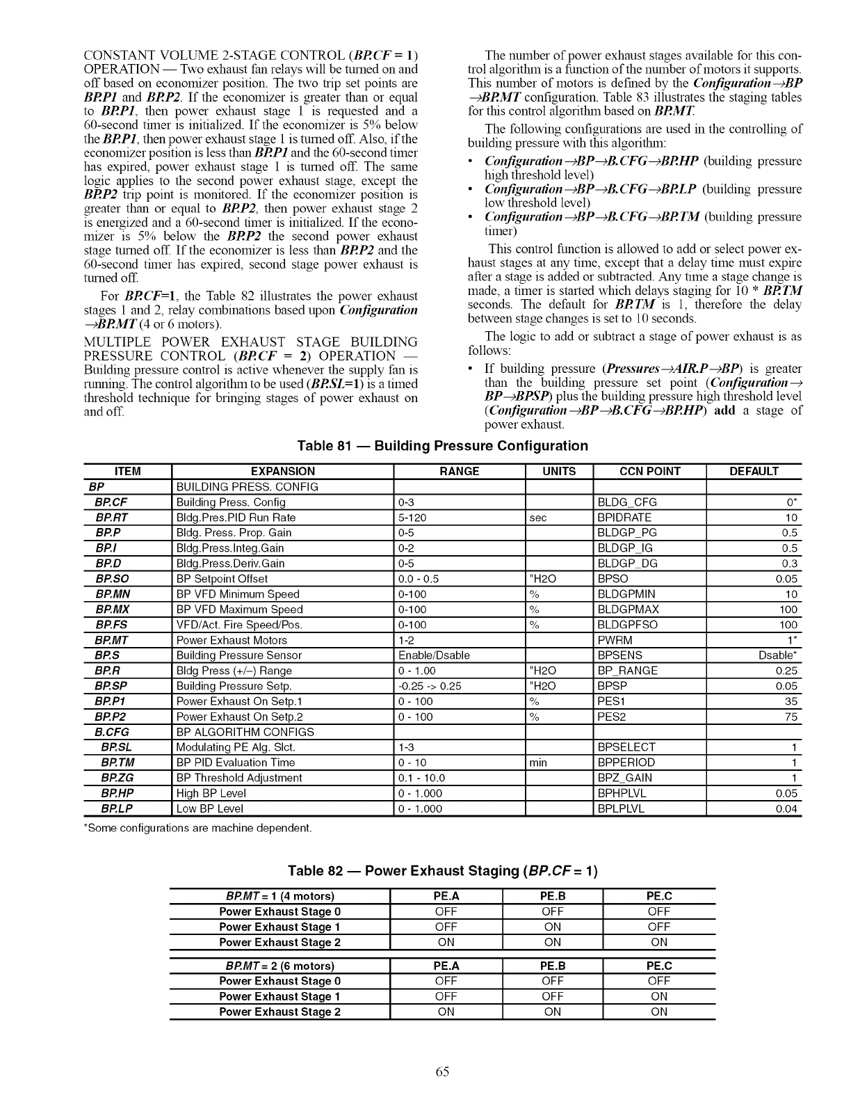
CONSTANTVOLUME2-STAGECONTROL(BRCF= 1)
OPERATION-- Twoexhaustfanrelayswillbeturnedonand
offbasedoneconomizerposition.Thetwotripsetpointsare
BRP! and BRP2. If the economizer is greater than or equal
to BRP1, then power exhaust stage 1 is requested and a
60-second thner is initialized. If the economizer is 5% below
theBRP1, then power exhaust stage 1 is turned off. Also, if the
economizer position is less than BRP1 and the 60-second timer
has expired, power exhaust stage 1 is turned off. The same
logic applies to the second power exhaust stage, except the
BRP2 trip point is monitored. If the economizer position is
greater than or equal to BRP2, then power exhaust stage 2
is energized and a 60-second timer is initialized. If the econo-
mizer is 5% below the BRP2 the second power exhaust
stage turned off. If the economizer is less than BRP2 and the
60-second thner has expired, second stage power exhaust is
turned off.
For BRCF=I, the Table 82 illustrates the power exhaust
stages 1 and 2, relay combinations based upon Configuration
-9BRMT (4 or 6 motors).
MULTIPLE POWER EXHAUST STAGE BUILDING
PRESSURE CONTROL (BRCF = 2) OPERATION --
Building pressure control is active whenever the supply fan is
running. The control algoritlnn to be used (BRSL=I) is a timed
threshold technique for bringing stages of power exhaust on
and off.
The number of power exhaust stages available for this con-
trol algorithin is a function of the number of motors it supports.
This number of motors is defined by the Configuration-9BP
-9BRMT configuration. Table 83 illustrates the staging tables
for this control algorithin based on BRMT.
The following configurations are used in the controlling of
building pressure with this algorithin:
•Configuration-9BP-9B.CFG-9BRHP (building pressure
high threshold level)
• Configuration-9BP-9B.CFG-9BRLP (building pressure
low threshold level)
• Configuration-9BP-9B. CFG-9BR TM (building pressure
timer)
This control function is allowed to add or select power ex-
haust stages at any time, except that a delay time must expire
after a stage is added or subtracted. Any time a stage change is
made, a timer is started which delays staging for 10 * BRTM
seconds. The default for BRTM is 1, therefore the delay
between stage changes is set to 10 seconds.
The logic to add or subtract a stage of power exhaust is as
follows:
If building pressure (Pressures-9AIR.P-9BP) is greater
than the building pressure set point (Configuration-9
BP-gBPSP) plus the building pressure high threshold level
(Configuration-gBP-gB.CFG-gBRHP) add a stage of
power exhaust.
Table 81 -- Building Pressure Configuration
ITEM EXPANSION RANGE UNITS CCN POINT DEFAULT
BP BUILDING PRESS. CONFIG
BP.CF Building Press. Config 0-3 BLDG_CFG O*
BP.RT Bldg.Pres.PID Run Rate 5-120 sec BPIDRATE 10
BP.P Bldg. Press. Prop. Gain 0-5 BLDGP_PG 0.5
BP.I Bldg.Press.lnteg.Gain 0-2 BLDGP_IG 0.5
BP.D Bldg.Press.Deriv.Gain 0-5 BLDGP_DG 0.3
BP.SO BP Setpoint Offset 0.0 - 0.5 "H20 BPSO 0.05
BP.MN BP VFD Minimum Speed 0-100 % BLDGPMIN 10
BP.MX BP VFD Maximum Speed 0-1O0 % BLDGPMAX 100
BP.FS VFD/Act. Fire Speed/Pos. 0-1O0 % BLDGPFSO 1O0
BP.MT Power Exhaust Motors 1-2 PWRM 1*
BP.S Building Pressure Sensor Enable/Dsable BPSENS Dsable*
BP.R Bldg Press (+/-) Range 0 - 1.00 "H20 BP_RANGE 0.25
BP.SP Building Pressure Setp. -0.25 -> 0.25 "H20 BPSP 0.05
BP.PI Power Exhaust On Setp.1 0 - 100 % PES1 35
BP.P2 Power Exhaust On Setp.2 0 - 100 % PES2 75
B.CFG BP ALGORITHM CONFIGS
BP.SL Modulating PE AIg. Slct. 1-3 BPSELECT 1
BP.TM BP PID Evaluation Time 0 - 10 min BPPERIOD 1
BP.ZG BP Threshold Adjustment 0.1 - 10.0 BPZ_GAIN 1
BP.HP High BP Level 0 - 1.000 BPHPLVL 0.05
BP.LP Low BP Level 0 - 1.000 BPLPLVL 0.04
•Some configurations are machine dependent.
Table 82 -- Power Exhaust Staging (BP.CF= 1)
BP.MT= 1 (4 motors) PE.A PE.B PE.C
Power Exhaust Stage 0 OFF OFF OFF
Power Exhaust Stage 1 OFF ON OFF
Power Exhaust Stage 2 ON ON ON
BP.MT= 2 (6 motors) PE.A PE.B PE.C
Power Exhaust Stage 0 OFF OFF OFF
Power Exhaust Stage 1 OFF OFF ON
Power Exhaust Stage 2 ON ON ON
65
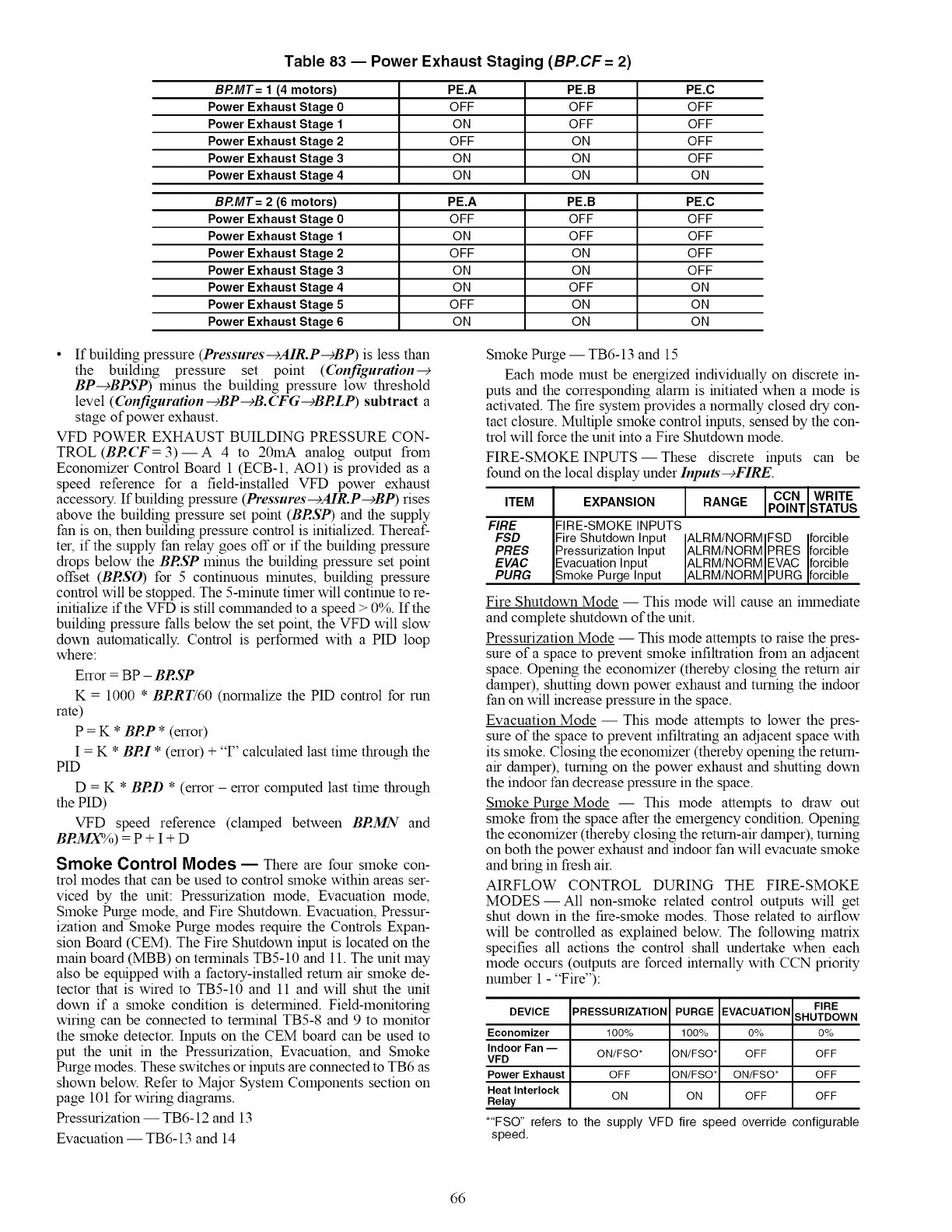
Table 83 -- Power Exhaust Staging (BP.CF= 2)
BP.MT= 1 (4 motors) PE.A PE.B PE.C
Power Exhaust Stage 0 OFF OFF OFF
Power Exhaust Stage 1 ON OFF OFF
Power Exhaust Stage 2 OFF ON OFF
Power Exhaust Stage 3 ON ON OFF
Power Exhaust Stage 4 ON ON ON
Bt_.MT= 2 (6 motors) PE.A PE.B PE.C
Power Exhaust Stage 0 OFF OFF OFF
Power Exhaust Stage 1 ON OFF OFF
Power Exhaust Stage 2 OFF ON OFF
Power Exhaust Stage 3 ON ON OFF
Power Exhaust Stage 4 ON OFF ON
Power Exhaust Stage 5 OFF ON ON
Power Exhaust Stage 6 ON ON ON
•If building pressure (Pressures-cAIR.P-cBP) is less than
the building pressure set point ((bnfiguration--+
BP--+BPSP) minus the building pressure low threshold
level ((bnfiguration--+BP--+B.(TG--+BRLP) subtract a
stage of power exhaust.
VFD POWER EXHAUST BUILDING PRESSURE CON-
TROL (BR(T = 3)--A 4 to 20mA analog output from
Economizer Control Board 1 (ECB-1, AO1) is provided as a
speed reference for a field-installed VFD power exhaust
accessory. If building pressure (Pressures---_AIR.P --+BP) rises
above the building pressure set point (BRSP) and the supply
fan is on, then building pressure control is initialized. Thereaf-
ter, if the supply fan relay goes off or if the building pressure
drops below the BRSP minus the building pressure set point
offset (BRSO) for 5 continuous minutes, building pressure
control will be stopped. The 5-minute timer will continue to re-
initialize if the VFD is still colrnnanded to a speed > 0%. If the
building pressure falls below the set point, the VFD will slow
down automatically. Control is performed with a PID loop
where
Error = BP - BRSP
K = 1000 * BRRT/60 (normalize the PID control for run
rate)
P = K * BRP * (error)
I = K * BRI * (error) + 'T' calculated last time through the
PID
D = K * BRD * (error - error computed last time through
the PID)
VFD speed reference (clamped between BRMN and
BRMX%) = P + I + D
Smoke Control Modes -- There are four smoke con-
trol modes that can be used to control smoke within areas ser-
viced by the unit: Pressurization mode, Evacuation mode,
Smoke Purge mode, and Fire Shutdown. Evacuation, Pressur-
ization and Smoke Purge modes require the Controls Expan-
sion Board (CEM). The Fire Shutdown input is located on the
main board (MBB) on terminals TB5-10 and 11. The unit may
also be equipped with a factory-installed remm air smoke de-
tector that is wired to TB5-10 and 11 and will shut the unit
down if a smoke condition is determined. Field-monitoring
wiring can be connected to terminal TB5-8 and 9 to monitor
the smoke detector. Inputs on the CEM board can be used to
put the unit in the Pressurization, Evacuation, and Smoke
Purge modes. These switches or inputs are connected to TB6 as
shown below. Refer to Major System Components section on
page 101 for wiring diagrmns.
Pressurization -- TB6-12 and 13
Evacuation -- TB6-13 and 14
Smoke Purge -- TB6-13 and 15
Each mode must be energized individually on discrete in-
puts and the corresponding alarm is initiated when a mode is
activated. The fire system provides a normally closed dry con-
tact closure. Multiple smoke control inputs, sensed by the con-
trol will force the unit into a Fire Shutdown mode.
FIRE-SMOKE INPUTS -- These discrete inputs
found on the local display under Inputs-cFIRE
ITEM
FIRE
FSD
PRES
EVAC
PURG
can be
I I CCN WRITEEXPANSION RANGE PO NT STATUS
IFIRE-SMOKE INPUTS
IFire Shutdown Input ALRM/NORMIFSD forcible
pressurization Input ALRM/NORMiPRES forcible
IEvacuation Input ALRM/NORM EVAC forcible
]Smoke Purge Input ALRM/NORM PURG forc b e
Fire Shutdown Mode -- This mode will cause an ilrnnediate
and complete shutdown of the unit.
Pressurization Mode -- This mode attempts to raise the pres-
sure of a space to prevent smoke infiltration from an adjacent
space. Opening the economizer (thereby closing the return air
damper), shutting down power exhaust and turning the indoor
fan on will increase pressure in the space.
Evacuation Mode -- This mode attempts to lower the pres-
sure of the space to prevent infiltrating an adjacent space with
its smoke. Closing the economizer (thereby opening the return-
air damper), turning on the power exhaust and shutting down
the indoor fan decrease pressure in the space.
Smoke Purge Mode -- This mode attempts to draw out
smoke from the space after the emergency condition. Opening
the economizer (thereby closing the return-air damper), turning
on both the power exhaust and indoor fan will evacuate smoke
and bring in fresh air.
AIRFLOW CONTROL DURING THE FIRE-SMOKE
MODES- All non-smoke related control outputs will get
shut down in the fire-smoke modes. Those related to airflow
will be controlled as explained below. The following matrix
specifies all actions the control shall undertake when each
mode occurs (outputs are forced internally with CCN priority
number 1 -"Fire"):
DEVICE
Economizer
Indoor Fan --
VFD
Power Exhaust
Heat Interlock
Relay
PRESSURIZATION PURGE EVACUATION
100% 100% 0%
ON/FSO* ON/FSO* OFF
OFF ON/FSO* ON/FSO*
ON ON OFF
FIRE
SHUTDOWN
0%
OFF
OFF
OFF
*"FSO" refers to the supply VFD fire speed override configurable
speed.
66
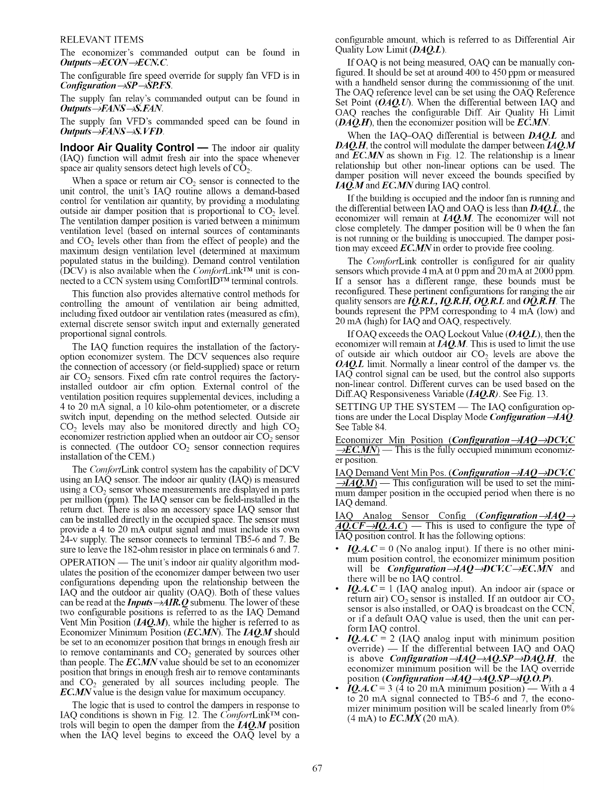
RELEVANT ITEMS
The economizer's commanded output can be found in
Outputs" -+E CON-+E CN. C
The configurable fire speed override for supply fan VFD is in
Configuration --+SP --+SRFS.
The supply fan relay's commanded output can be found in
Outputs'--+FANS--+S.FAN.
The supply fan VFD's colmnanded speed can be found in
Outputs--+FANS --+S.VFD.
Indoor Air Quality Control -- The indoor air quality
(IAQ) function will admit flesh air into the space whenever
space air quality sensors detect high levels of CO2.
When a space or return air CO2 sensor is connected to the
unit control, the unit's IAQ routine allows a demand-based
control for ventilation air quantity, by providing a modulating
outside air damper position that is proportional to CO2 level.
The ventilation damper position is varied between a minimum
ventilation level (based on internal sources of contaminants
and CO2 levels other than from the effect of people) and the
maximum design ventilation level (determined at maximum
populated status in the building). Demand control ventilation
(DCV) is also available when the (_n_fortLink TM unit is con-
nected to a CCN system using ComfortID TM terminal controls.
This function also provides alternative control methods for
controlling the amount of ventilation air being admitted,
including fixed outdoor air ventilation rates (measured as cfm),
external discrete sensor switch input and externally generated
proportional signal controls.
The IAQ function requires the installation of the factory-
option economizer system. The DCV sequences also require
the connection of accessory (or field-supplied) space or return
air CO2 sensors. Fixed cfm rate control requires the factory-
installed outdoor air cfm option. External control of the
ventilation position requires supplemental devices, including a
4 to 20 mA signal, a 10 kilo-otnn potentiometer, or a discrete
switch input, depending on the method selected. Outside air
CO 2 levels may also be monitored directly and high CO 2
economizer restriction applied when an outdoor air CO2 sensor
is connected. (The outdoor CO2 sensor connection requires
installation of the CEM.)
The (_n_fortLink control system has the capability of DCV
using an IAQ sensor. The indoor air quality (IAQ) is measured
using a CO2 sensor whose measurements are displayed in parts
per million (ppm). The IAQ sensor can be field-installed in the
return duct. There is also an accessory space IAQ sensor that
can be installed directly in the occupied space. The sensor must
provide a 4 to 20 mA output signal and must include its own
24-v supply. The sensor connects to terminal TB5-6 and 7. Be
sure to leave the 182-ohin resistor in place on terminals 6 and 7.
OPERATION -- The unit's indoor air quality algorithin mod-
ulates the position of the economizer damper between two user
configurations depending upon the relationship between the
IAQ and the outdoor air quality (OAQ). Both of these values
can be read at the Inputs--+AIR. Q submenu. The lower of these
two configurable positions is referred to as the IAQ Demand
Vent Min Position (IAQ.M), while the higher is referred to as
Economizer Minimum Position (EC.MN). The IAQ.M should
be set to an economizer position that brings in enough fresh air
to remove contaminants and CO2 generated by sources other
than people. The EC.MNvalue should be set to an economizer
position that brings in enough fresh air to remove contaminants
and CO2 generated by all sources including people. The
EC.MNvalue is the design value for maxflnum occupancy.
The logic that is used to control the dampers in response to
IAQ conditions is shown in Fig. 12. The (_nfortLink TM con-
trols will begin to open the damper from the IAQ.M position
when the IAQ level begins to exceed the OAQ level by a
configurable amount, which is referred to as Differential Air
Quality Low Limit (DAQ.L).
If OAQ is not being measured, OAQ can be manually con-
figured. It should be set at around 400 to 450 ppm or measured
with a handheld sensor during the colrunissioning of the unit.
The OAQ reference level can be set using the OAQ Reference
Set Point (OAQ. U). When the differential between IAQ and
OAQ reaches the configurable Diff. Air Quality Hi Limit
(DAQ.H), then the economizer position will be ECMN.
When the IAQ-OAQ differential is between DAQ.L and
DAQ.H, the control will modulate the damper between IAQ.M
and ECMN as shown in Fig. 12. The relationship is a linear
relationship but other non-linear options can be used. The
damper position will never exceed the bounds specified by
IAQ.M and ECMN during IAQ control.
If the building is occupied and the indoor fan is running and
the differential between IAQ and OAQ is less than DAQ.L, the
economizer will remain at IAQ.M. The economizer will not
close completely. The damper position will be 0 when the fan
is not running or the building is unoccupied. The damper posi-
tion may exceed ECMNin order to provide free cooling.
The (_nfortLink controller is configured for air quality
sensors which provide 4 mA at 0 ppm and 20 mA at 2000 ppm.
If a sensor has a different range, these bounds must be
reconfigured. These pertinent configurations for ranging the air
quality sensors are IQ.R.L, IQ.R.H, OQ.R.L and OQ.R.H. The
bounds represent the PPM corresponding to 4 mA (low) and
20 mA (high) for IAQ and OAQ, respectively.
IfOAQ exceeds the OAQ Lockout Value (OAQ.L), then the
economizer will remain at IAQ.M. This is used to limit the use
of outside air which outdoor air CO2 levels are above the
OAQ.L limit. Normally a linear control of the damper vs. the
IAQ control signal can be used, but the control also supports
non-linear control. Different curves can be used based on the
Diff.AQ Responsiveness Variable (IAQ.R). See Fig. 13.
SETT_G UP THE SYSTEM -- The IAQ configuration op-
tions are under the Local Display Mode Configuration--+IAQ.
See Table 84.
Economizer Min Position ((bnfiguration--+IAQ--+DCV.C
--+EC.MN) -- This is the fully occupied minimum economiz-
er position.
IAQ Demand Vent Min Pos. (Con.figuration--+IAQ--+DCV.C
--+IAQ.M) -- This configuration will be used to set the mini-
1hum damper position in the occupied period when there is no
IAQ demand.
IAQ Analog Sensor Config (Configuration-9IAQ--9
AQ.(T-+IQ.A.() -- This is used to configure the type of
IAQ position control. It has the following options:
•IQ.A. C = 0 (No analog input). If there is no other mini-
mum position control, the economizer minimum position
will be (bnfiguration--+IAQ--gDCV.C--+E(:MN and
there will be no IAQ control.
• IQ.A. C = 1 (IAQ analog input). An indoor air (space or
return air) CO2 sensor is installed. If an outdoor air CO2
sensor is also installed, or OAQ is broadcast on the CCN,
or if a default OAQ value is used, then the unit can per-
form IAQ control.
• IQ.A.C = 2 (IAQ analog input with minimum position
override) -- If the differential between IAQ and OAQ
is above Configuration---_IAQ--)AQ.SP-+DAQ.11, the
economizer minimum position will be the IAQ override
position ((bnfiguration---_IAQ---_AQ.SP---_IQ.O.P).
• IQ.A. C = 3 (4 to 20 mA minimum position) -- With a 4
to 20 mA signal connected to TB5-6 and 7, the econo-
mizer minimum position will be scaled linearly from 0%
(4 mA) to EC.MX (20 mA).
67
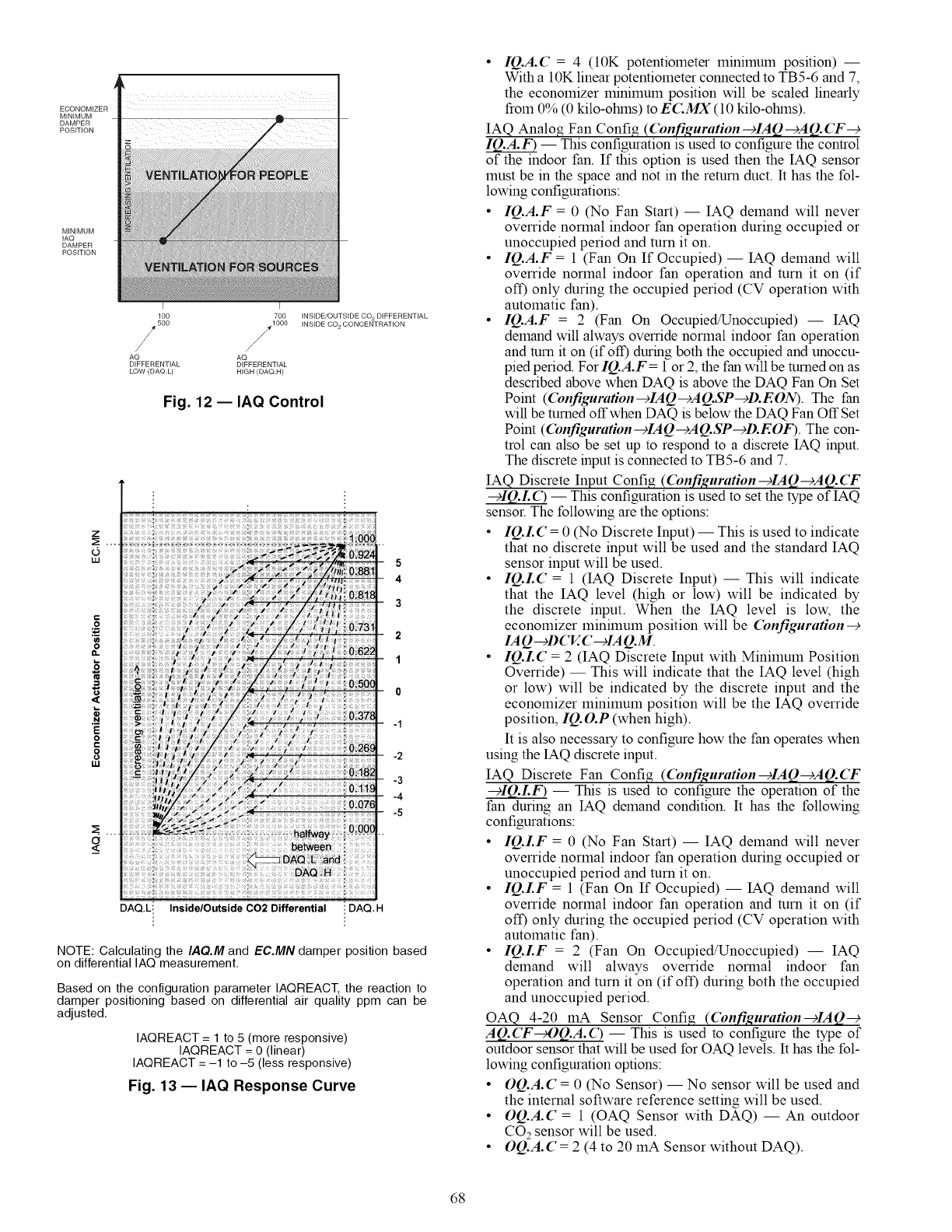
ECONOMIZER
MINIMUM
DAMPER
POSITION
MINIMUM
IAQ
DAMPER
POSITION
lOO
5oo
/
/
AQ AQ
DIFFERENTIAL DIFFERENTIAL
LOW (DAQ.L) HIGH (DAQ.H)
700 INSIDE/OUTSIDE CO 2 DIFFERENTIAL
10O0 INSIDE CO 2 CONCENTRATION
s
Fig. 12 -- IAQ Control
Z...
"6
Iii
<o
...................
;: : P_{ { ,I !: I/ ill 08_
,;;;: _at_y ;i-0--0-0--(:
i :: :; ; : i i : BAQ B :
: :: { :f i ;;;
5
4
3
2
1
0
-1
-2
-3
-4
-5
DAQ.L! InsidelOutside 002 Differential i DAQ.H
NOTE: Calculating the IAQ.M and EC.MN damper position based
on differential IAQ measurement,
Based on the configuration parameter IAQREACT, the reaction to
damper positioning based on differential air quality ppm can be
adjusted,
IAQREACT = 1 to 5 (more responsive)
IAQREACT = 0 (linear)
IAQREACT = -1 to-5 (less responsive)
Fig. 13 -- IAQ Response Curve
• IQ.A.C = 4 (10K potentiometer minimum position) --
With a 10K linear potentiometer connected to TB5-6 and 7_
the economizer minimum position will be scaled linearly
from 0% (0 kilo-otnns) to ECMX (10 kilo-otnns).
IAQ Analog Fan Config (Configuration---_IAQ---_AQ. _T---_
!Q.A.F) -- This configuration is used to configure the control
of the indoor fan. If this option is used then the IAQ sensor
must be in the space and not in the return duct. It has the fol-
lowing configurations:
• IQ.A.F = 0 (No Fan Start) -- IAQ demand will never
override normal indoor fan operation during occupied or
unoccupied period and turn it on.
• IQ.A.F = 1 (Fan On If Occupied) -- IAQ demand will
override normal indoor fan operation and turn it on (if
off) only during the occupied period (CV operation with
automatic fan).
• IQ.A.F = 2 (Fan On Occupied/Unoccupied) -- IAQ
demand will always override normal indoor fan operation
and turn it on (if off) during both the occupied and unoccu-
pied period. For IQ.A.F = 1 or 2_the fan will be turned on as
described above when DAQ is above the DAQ Fan On Set
Point ((bnfigurafion--+IAQ--+AQ.SP--+D.EON). The fan
will be turned offwhen DAQ is below the DAQ Fan OffSet
Point ((bnfiguration--_IAQ--+AQ.SP--_D.EOF). The con-
trol can also be set up to respond to a discrete IAQ input.
The discrete input is connected to TB5-6 and 7.
IAQ Discrete Input Config ((bn.figuration--+IAQ--+AQ.(T
--+IQ.L(3 -- This configuration is used to set the type of IAQ
sensor. The following are the options:
• IQ.LC = 0 (No Discrete Input) -- This is used to indicate
that no discrete input will be used and the standard IAQ
sensor input will be used.
• IQ.LC = 1 (IAQ Discrete Input) -- This will indicate
that the IAQ level (high or low) will be indicated by
the discrete input. When the IAQ level is low_ the
economizer minimum position will be Configuration--+
IA Q--+DCV..C --+IAQ.M.
• IQ.LC = 2 (IAQ Discrete Input with Minimum Position
Override) -- This will indicate that the IAQ level (high
or low) will be indicated by the discrete input and the
economizer minimum position will be the IAQ override
position_ IQ. O.P (when high).
It is also necessary to configure how the fan operates when
using the IAQ discrete input.
IAQ Discrete Fan Config ((bn.figuration--+IAQ--+AQ.(T
--+IQ.LF) -- This is used to configure the operation of the
fan during an IAQ demand condition. It has the following
configurations:
• IQ.LF = 0 (No Fan Start) -- IAQ demand will never
override normal indoor fan operation during occupied or
unoccupied period and turn it on.
• IQ.LF = 1 (Fan On If Occupied) -- IAQ demand will
override normal indoor fan operation and turn it on (if
off) only during the occupied period (CV operation with
automatic fan).
• IQ.LF = 2 (Fan On Occupied/Unoccupied) -- IAQ
demand will always override normal indoor fan
operation and turn it on (if off) during both the occupied
and unoccupied period.
OAQ 4-20 mA Sensor Config (Con.figuration--+IAQ--+
AQ.(T_OQ.A.(3 -- This is used to configure the type of
outdoor sensor that will be used for OAQ levels. It has the fol-
lowing configuration options:
• OQ.A. C = 0 (No Sensor) -- No sensor will be used and
the internal software reference setting will be used.
• OQ.A.C = 1 (OAQ Sensor with DAQ) -- An outdoor
CO 2sensor will be used.
• OQ.A. C = 2 (4 to 20 mA Sensor without DAQ).
68
IAO Econo Override Pos (Configuration-+IAQ-+AQ.SP-+
-- This configuration is the position that the econo-
mizer goes to when override is in effect.
Diff. Air Quality Lo Limit (Configuration--+IAQ--+AQ.SP
-+DAQ.L) -- This is the differential CO2 level at which IAQ
control of the dampers will be initiated.
Diff. Air Quality Hi Limit (Configuration-+IAQ-+AQ.SP
-+DAQ.H) -- This is the differential CO 2level at which IAQ
control of the dampers will be at maximum and the dampers
will be at the Configuration-+IAQ-+DCV..C-+EC.MN.
DAQ ppm Fan Off Set Point (Con.figuration-+IAQ
-+AQ.SP-+D.EOF) -- This is the CO 2level at which the
indoor fan will be turned off.
DAQ ppm Fan On Set Point (Configuration
--+IAQ--+AQ.SP--+D.EON) -- This is the CO2 level at which
the indoor fan will be turned on.
Diff. IAQ Responsiveness (Con.figuration-+IAQ-+AQ.SP
-+IAQ.R) -- This is the configuration that is used to select the
IAQ response curves as shown in Fig. 13.
OAQ Lockout Value (Con.figuration-+IAQ-+AQ.SP-+
OAQ.L) -- This is the maxhnum OAQ level above which de-
mand ventilation will be disabled.
User Determined OAQ (Con.figuration-+IAQ--)AQ.SP-+
OAQ.U) -- If an OAQ sensor is unavailable, the user can
manually set the OAQ reading.
IAQ Low Reference (Con.figuration---_IAQ---_AQ.S.R---_
!Q.R.L) -- This is the reference that will be used with a
non-Carrier IAQ sensor that may have a different characteristic
curve. It represents the CO2level at 4 mA.
IAQ High Reference (Con.figuration --_IAQ---_AQ.S.R
-+IQ.R.H) -- This is the reference that will be used with a
non-Carrier IAQ sensor that may have a different characteristic
curve. It represents the CO2level at 20 mA.
OAQ Low Reference ((bnfiguration---_IAQ---_AQ.S.R
_OQ.R.L) -- This is the reference that will be used with a
non-Carrier OAQ sensor that may have a different characteris-
tic curve. It represents the CO2 level at 4 mA.
OAQ High Reference (Con.figuration---_IAQ---_AQ.S.R---_
OQ.R.H) -- This is the reference that will be used with a non-
Carrier OAQ sensor that may have a different characteristic
curve. It represents the CO2level at 20 mA.
PRE-OCCUPANCY PURGE- The control has the option
for a pre-occupancy purge to refresh the air in the space prior to
occupancy.
This feature is enabled by setting (bnfiguration-+IAQ-+
IAQ.P-+IQ.PG to Yes.
The IAQ purge will operate under the following conditions:
•IQ.PG is enabled
•the unit is in the unoccupied state
•Current Time is valid
•Next Occupied Time is valid
•time is within two hours of the next occupied period
•time is within the purge duration (Configuration-+
IA Q--+IAQ.P--+IQ.R I)
If all of the above conditions are met, the following logic is
used:
If OAT > IQ.L.O and OAT < OCSP and economizer is
available then purge will be enabled and the economizer will
be colmnanded to 100%.
If OAT < IQ.L.O then the economizer will be positioned to
the IAQ Purge LO Temp Min Pos ((bnfiguration--+
IAQ--+IAQ.P--+IQ.RL )
If neither of the above are true then the dmnpers will be
positioned to the IAQ Purge HI Temp Min PUs ((bnfiguration
--+IAQ--+IAQ.P--+IQ.P.H)
If this mode is enabled the indoor fan and heat interlock
relay (VAV) will be energized.
IAQ Purge (Configuration --+IA Q -+ IA Q.P --+IQ.PG) --
This is used to enable IAQ pre-occupancy purge.
IAQ Purge Duration (Con.figuration--+IAQ--+IAQ.P--+
-- This is the maximum amount of time that a purge
call occur.
IAQ Purge Lo Temp Min Pos (Configuration-+IAQ-+
IAQ.P-+IQ.RL) -- This is used to configure a low limit for
damper position to be used during the purge mode.
IAQ Purge Hi Temp Min Pos (Configuration-+IAQ-+
IAQ.P-+IQ.RH) -- This is used to configure a maximum po-
sition for the dampers to be used during the purge cycle.
IAQ Purge OAT Lockout Temp (Configuration-+IAQ-+
IAQ.P-+IQ.L.O) --Nightthne lockout temperature below
which the purge cycle will be disabled.
Dehumidification and Reheat EThe Dehumidifi-
cation function will override comfort condition set points
based on dry bulb temperature and deliver cooler air to the
space in order to satisfy a humidity set point at the space or
return air humidity sensor. The Reheat function will energize a
suitable heating system concurrent with dehumidification
sequence should the dehumidification operation result in
excessive cooling of the space condition.
The dehumidification sequence requires the installation of a
space or return air humidity sensor or a discrete switch input.
An ECB option is required to accolmnodate an RH (relative
humidity) sensor connection. A CEM (option or accessory) is
required to accomodate an RH switch. Reheat is possible when
multiple-step staged gas control option or hydronic heat field-
installed coil is installed. Reheat is also possible using a heat
reclahn coil (field-supplied and installed) or a DX (direct ex-
pansion) reheat coil.
Dehumidification and reheat control are allowed during
Cooling and Vent modes in the Occupied period.
On constant volume units using thermostat inputs (C TYP =
3 or 4), the discrete switch input must be used as the dehumidi-
fication control input. The colrnnercial Thermidistat TM device
is the recolmnended accessory device.
SETTING UP THE SYSTEM -- The settings for dehumidi-
fication can be found at the local display at Configuration-+
DEHU. See Table 85.
Dehumidification Configuration (D.SEL) -- The dehumidi-
fication configuration can be set for the following settings:
• D.SEL = 0 -- No dehumidification and reheat.
• D.SEL = 1 -- The control will perform dehumidification
and reheat with staged gas only.
• D.SEL = 2 -- The control will perform both dehumidifi-
cation and reheat with third party heat via an alarm relay.
In the case of D.SEL=2, during dehumidification, the
alarm relay will close to convey the need for reheat. A
typical application might be to energize a 3-way valve to
perform DX reheat.
Dehumidification Sensor (D.SEN) -- The sensor can be con-
figured for the following settings:
• D.SEN = 1 -- Initiated by return air relative humidity
sensor.
• D.SEN = 2 -- Initiated by discrete input.
Economizer Disable in Dehum Mode (D.E(:D) -- This
configuration determines economizer operation during Dehu-
midification mode.
• D.E(:D = YES -- Economizer disabled during dehu-
midification (default).
• D.E(:D = NO -- Economizer not disabled during dehu-
midification.
69
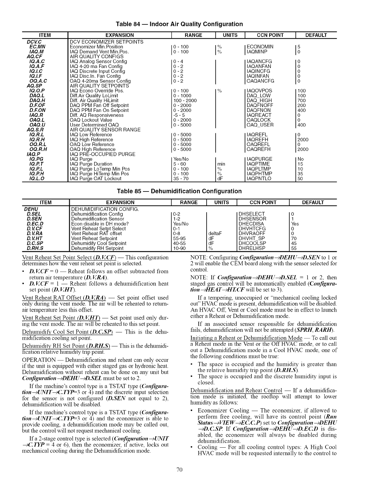
ITEM
DCVC
EC.MN
IAQ.M
AQ.CF
IQ.A.C
IQ.A.F
IQ.LC
IQ.LF
OQ.A.C
AQ.SP
IQ.O.P
DAQ.L
DAQ.H
D.F.OF
D.F.ON
IAQ.R
OAQ.L
OAQ.U
AQ.S.R
IQ.R.L
IQ.R.H
OQ.R.L
OQ.R.H
IAQ.P
IQ.PG
IQ.P.T
IQ.P.L
IQ.P.H
IQ.L.O
Table 84 -- Indoor Air Quality Configuration
EXPANSION
DCV ECONOMIZER SETPOINTS
Economizer Min.Position
IAQ Demand Vent Min.Pos.
AIR QUALITY CONFIGS
IAQ Analog Sensor Config
IAQ 4-20 ma Fan Config
IAQ Discrete Input Config
IAQ Disc.In. Fan Config
OAQ 4-20ma Sensor Config
] RANGE ] UNITS
O-100 %
0 - 100 %
0-4
0-2
0-2
0-2
0-2
AIR QUALITY SETPOINTS
IAQ Econo Override Pos.
Dill.Air Quality LoLimit
Diff. Air Quality HiLimit
DAQ PPM Fan Off Setpoint
DAQ PPM Fan On Setpoint
Diff. AQ Responsiveness
OAQ Lockout Value
User Determined OAQ
0-100
0-1000
100-2000
0-2000
0-2000
-5-5
0-2000
0-5000
AIR QUALITY SENSOR RANGE
IAQ Low Reference
IAQ High Reference
OAQ Low Reference
OAQ High Reference
IAQ PRE-OCCUPIED PURGE
IAQ Purge
IAQ Purge Duration
IAQ Purge LoTemp Min Pos
IAQ Purge HiTemp Min Pos
IAQ Purge OAT Lockout
0-5000
0-5000
0-5000
0-5000
Yes/No
5-60
0-100
0-100
35 -70
ICON POINT I DEFAULT
I ECONOMIN
IAQMINP
IAQANCFG
IAQANFAN
IAQINCFG
IAQINFAN
OAQANCFG
% IAQOVPOS
DAQ LOW
DAQ HIGH
DAQFNOFF
DAQFNON
IAQREACT
OAQLOCK
OAQ USER
IAQREFL
IAQREFH
OAQREFL
OAQREFH
rain I IAQPURGE
IAQPTIME
iF IAQPLTMP
IAQPHTMP
IAQPNTLO
5
Io
o
o
o
o
o
1oo
1oo
7oo
2oo
4oo
o
o
4oo
o
2000
o
2000
No
15
10
35
5O
Table 85 -- Dehumidification Configuration
ITEM
DEHU
D.SEL
D.SEN
D.EC.D
D.VCF
D.VRA
D.VHT
D.C.SP
D.RH.S
EXPANSION
DEHUMIDIFICATION CONFIG.
Dehumidification Config
Dehumidification Sensor
Econ disable in DH mode?
Vent Reheat Setpt Select
Vent Reheat RAT offset
Vent Reheat Setpoint
Dehumidify Cool Setpoint
Dehumidify RH Setpoint
Vent Reheat Set Point Select (D. V.CF) -- This configuration
determines how the vent reheat set point is selected.
•D.V..(T = 0 -- Reheat follows an offset subtracted from
return air temperature (D. V.RA).
•D.V..(T = 1 -- Reheat follows a dehumidification heat
set point (D. V..HT).
Vent Reheat RAT Offset (D. V..RA) -- Set point offset used
only during the vent mode. The air will be reheated to return-
air temperature less this offset.
Vent Reheat Set Point (D. V..HT) -- Set point used only dur-
ing the vent mode. The air will be reheated to this set point.
Dehumidify Cool Set Point (D.C.SP) -- This is the dehu-
midification cooling set point.
Dehumidity RH Set Point (D.RH.S) -- This is the dehumidi-
fication relative humidity trip point.
OPERATION -- Dehumidification and reheat can only occur
if the unit is equipped with either staged gas or hydronic heat.
Dehumidification without reheat can be done on any unit but
Configuration--+DEHU--+D.SEL must be set to 2.
If the machine's control type is a TSTAT type (Configura-
tion-+UNIT_C TYP=-3 or 4) and the discrete input selection
for the sensor is not configured (D.SEN not equal to 2),
dehumidification will be disabled.
If the machine's control type is a TSTAT type ((bnfigura-
tion--+UNIT4:TYP=-3 or 4) and the economizer is able to
provide cooling, a dehumidification mode may be called out,
but the control will not request mechanical cooling.
If a 2-stage control type is selected ((bnfiguration--+UNIT
4: !TP = 4 or 6), then the economizer, if active, locks out
mechanical cooling during the Dehumidification mode.
IRANGE I UNITS I CCNPOINT IDEFAULT
0-2
1-2
Yea/No
i_ 95 dFdeltaFdF
I 10-90 %
I
DHSELECT ?
DHSENSOR
DHECDISA _es
DHVHTCFG
DHVRAOFF
DHVHT SP _
DHCOOLSP 45
DHRELHSP
NOTE: Configuring Configuration-+DEHU-+D.SENto 1 or
2 will enable the CEM board along with the sensor selected for
control.
NOTE: If (bnfiguration--+DEHU--+D.SEL = 1 or 2, then
staged gas control will be automatically enabled (Configura-
tion-+HEAT-+HT.CF will be set to 3).
If a tempering, unoccupied or "mechanical cooling locked
out" HVAC mode is present, dehumidification will be disabled.
An HVAC Off, Vent or Cool mode must be in effect to launch
either a Reheat or Dehumidification mode.
If an associated sensor responsible for dehumidification
fails, dehumidification will not be attempted (SPRH, RARH).
Initiating a Reheat or Dehumidification Mode -- To call out
a Reheat mode in the Vent or the Off HVAC mode, or to call
out a Dehumidification mode in a Cool HVAC mode, one of
the following conditions must be true:
• The space is occupied and the humidity is greater than
the relative humidity trip point (D.RH.S).
• The space is occupied and the discrete humidity input is
closed.
Dehumidification and Reheat Control -- If a dehumidifica-
tion mode is initiated, the rooftop will attempt to lower
humidity as follows:
• Economizer Cooling -- The economizer, if allowed to
perform free cooling, will have its control point (Run
Status-+VIEW--+EC C P) set to Configuration---_DEHU
--+D.C.SP If Configuration--+DEHU-+D.EC.D is dis-
abled, the economizer will always be disabled during
dehmnidification.
• Cooling -- For all cooling control types: AHigh Cool
HVAC mode will be requested internally to the control to
70

maintaindiagnostics,althoughtheenduserwill seea
Dehumidificationmodeat thedisplay.In addition,for
multi-stagecoolingunitsthecoolingcontrolpointwill
besetto Configuration-+DEHU-+D.C.SP (no SASP
reset is applied).
• Reheat When Cooling Demand is Present -- For reheat
control during dehmnidification: If reheat follows an
offset subtracted from return-air temperature (Configu-
ration---_DEHU---_D.SEL = 2), then no heating will be
initiated and the alarm relay will be energized. If
Configuration--cDEHU-+D.SEL = 1 and Configura-
tion--+HEAT--cHT.(T = staged gas or hot water valve,
then the selected heating control type will operate in the
low heat/modulating mode.
• The heating control point will be whatever the actual
cooling set point would have been (without any supply
air reset applied).
• Reheat During Vent Mode -- If configured (Configura-
tion--+DEHU--+D.V.(T = 0), the heating control point
will be equal to RAT - D. ERA. If configured (Configu-
ration--+DEHU--+D.V.(T 1), the heating control point
will be equal to the D. V.HT set point.
Ending Dehumidification and Reheat Control -- When ei-
ther the humidity sensor fall 5% below the set point ((bnfigu-
ration-+DEHU-+D.RH.S) or the discrete input reads
"LOW", the Dehumidification mode will end.
Temperature Compensated Start -- This logic is
used when the unit is in the unoccupied state. The control will
calculate early Start Bias time based on Space Temperature
deviation from the occupied cooling and heating set points.
This will allow the control to start the unit so that the space is at
conditioned levels when the occupied period starts. This is
required for ASHRAE 90.1 compliance. Aspace sensor is re-
quired for non-linkage applications.
SETTING UP THE SYSTEM -- The settings for tempera-
ture compensated start can be found in the local display under
(bnfiguration --¢UNIT.
ITEM EXPANSION RANGE UNITS CCN POINT
TCS.C Temp,Cmp,Strt,Cool Factr 3 - 60 rain TCSTCOOL
TCS.H Temp,Cmp,Strt,Heat Factr 3 - 60 rain TCSTHEAT
TCST-Cool Factor (TCS. (3 -- This is the factor for the start
time bias equation for cooling.
TCST-Heat Factor (TCS./-!) -- This is the factor for the start
time bias equation for heating.
NOTE: Temperature compensated start is disabled when these
factors are set to 0.
TEMPERATURE COMPENSATED START LOGIC --
The following conditions must be met:
• Unit is in unoccupied state.
• Next occupied time is valid.
• Current time of day is valid.
• Valid space temperature reading is available (sensor or
DAV-Linkage).
The algoritlun will calculate a Start Bias thne in minutes us-
ing the following equations:
If (space temperature > occupied cooling set point)
Start Bias Time = (space temperature - occupied cooling set
point)* TLS. C
If (space temperature < occupied heating set point)
Start Bias Time = (occupied heating set point - space
temperature)* TLS.H
When the Start Bias Time is greater than zero the algofitlun
will subtract it from the next occupied thne to calculate the new
start time. When the new start time is reached, the Temperature
Compensated Start mode is set (Operating Modes-+MODE--9
T.CS!), the fan is started and the unit controlled as in an
occupied state. Once set, Temperature Compensated mode will
stay on until the unit goes into the Occupied mode. The Start
Bias Time will be written into the CCN Linkage Equipment
Table if the unit is controlled in DAV mode. If the Unoccupied
Economizer Free Cool mode is active (Operating Modes--€
HVAC = "UNOCC FREE COOL") when temperature com-
pensated start begins, the Unoccupied Free Cool mode will be
stopped.
Carrier Comfort Network _ (CCN) System -- It
is possible to configure the (_l_fortLink TM control to partici-
pate as an element of the Carrier Comfort Network (CCN) sys-
tem directly from the local display. This section will deal with
explaining the various progralmnable options which are found
under the CCN sub-menu in the Configuration mode.
The major configurations for CCN progralmning are locat-
ed in the local displays at (bnfiguration _CCN See Table 86.
CCN Address (CCNA) -- This configuration is the CCN ad-
dress the rooftop is assigned.
CCN Bus Number (CCNB) -- This configuration is the CCN
bus the rooftop is assigned.
CCN Baud Rate (BAUD) -- This configuration is the CCN
baud rate.
CCN Time/Date Broadcast (TM.DT) -- If this configuration
is set to ON, the control will periodically send the time and date
out onto the CCN bus once a minute. If this device is on a CCN
network then it will be important to make sure that only one
device on the bus has this configuration set to ON. If more than
one thne broadcaster is present, problems with the time will
OCCUE
NOTE: Only the time and date broadcaster can perform
daylight savings time adjustments. Even if the rooftop is stand
alone, the user may want to set this to ON to accomplish the
daylight/savings function.
CCN OAT Broadcast (OAT.B) -- If this configuration is set
to ON, the control will periodically broadcast its outside-air
temperature at a rate of once every 30 minutes.
CCN OARH Broadcast (ORH.B) -- If this configuration is
set to ON, the control will periodically broadcast its outside air
relative humidity at a rate of once every 30 minutes.
CCN OAQ Broadcast (OAQ.B) -- If this configuration is set
to ON, the control will periodically broadcast its outside air
quality reading at a rate of once every 30 minutes.
Global Schedule Broadcast (GS.B) --If this configuration is
set to ON and the schedule number (S(!-L.N) is between 65 and
99, then the control will broadcast the internal time schedule
once every 2 minutes.
CCN Broadcast Acknowledger (B.ACIO -- If this configu-
ration is set to ON, then when any broadcasting is done on the
bus, this device will respond to and acknowledge. Only one de-
vice per bus can be configured for this option.
Schedule Number (SC!-LN) -- This configuration determines
what schedule the control may follow.
SCH.N = 0 The control is always occupied.
SCH.N = 1 The control follows its internal time sched-
ules. The user may enter any number
between 1 and 64 but it will be overwritten
to "1" by the control as it only has one
internal schedule.
SCH.N = 65-99 The control is either set up to receive to a
broadcasted time schedule set to this
number or the control is set up to broadcast
its internal time schedule (GS.B) to the
network and this is the global schedule
number it is broadcasting. If this is the case,
then the control still follows its internal time
schedules.
71
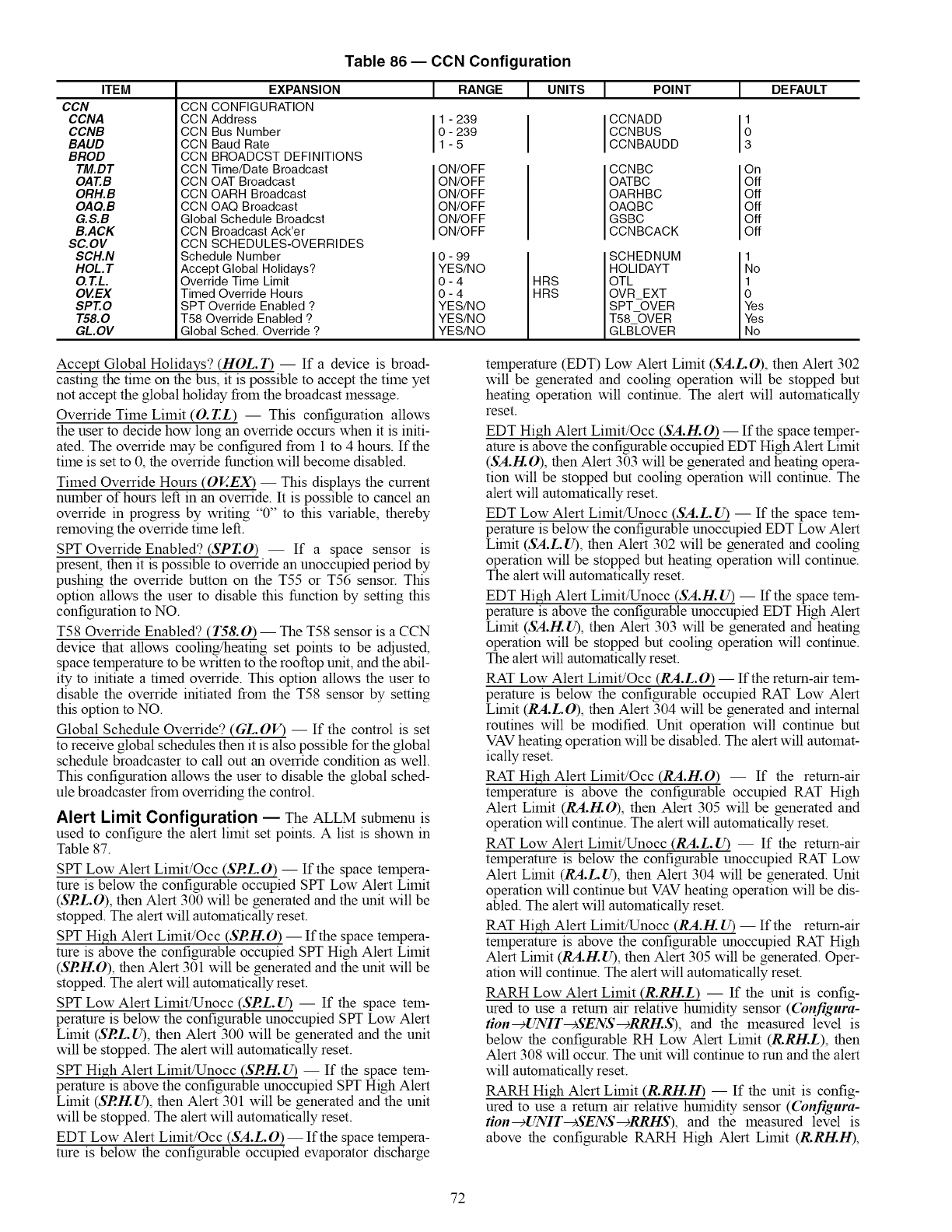
ITEM
CCN
CCNA
CCNB
BAUD
BROD
TM.DT
OAT.B
ORH.B
OAQ.B
G.S.B
B.ACK
SC.OV
SCH.N
HOL. T
O.T.L.
OVEX
SPT.O
T58.0
GL.OV
Table 86 -- CCN Configuration
EXPANSION
CCN CONFIGURATION
CCN Address
CCN Bus Number
CCN Baud Rate
CCN BROADCST DEFINITIONS
CCN Time/Date Broadcast
CCN OAT Broadcast
CCN OARH Broadcast
CCN OAQ Broadcast
Global Schedule Broadcst
CCN Broadcast Ack'er
CCN SCHEDULES-OVERRIDES
Schedule Number
Accept Global Holidays?
Override Time Limit
Timed Override Hours
SPT Override Enabled ?
T58 Override Enabled ?
Global Sched. Override ?
IRANGEI UNITS IDEFAULT
0
3
- 239
- 239
-5
ON/OFF
ON/OFF
ON/OFF
ON/OFF
ON/OFF
ON/OFF
0 - 99
IYES/NO
0-4
0-4
YES/NO
YES/NO
YES/NO
HRS
HRS
I POINT
ICCNADD
CCNBUS
CCNBAUDD
CCNBC
OATBC
OARHBC
OAQBC
GSBC
CCNBCACK
SCHEDNUM
HOLIDAYT
OTL
OVR_EXT
SPT OVER
T58_OVER
GLBLOVER
On
Off
Off
Off
Off
Off
1
No
1
0
Yes
Yes
No
Accept Global Holidays? (HOL. T) -- If a device is broad-
casting the time on the bus, it is possible to accept the time yet
not accept the global holiday from the broadcast message.
Override Time Limit (O. T.L) -- This configuration allows
the user to decide how long an override occurs when it is initi-
ated. The override may be configured from 1 to 4 hours. If the
time is set to 0, the override function will become disabled.
Timed Override Hours (OV..EX) -- This displays the current
number of hours left in an override. It is possible to cancel an
override in progress by writing "0" to this variable, thereby
removing the override trine left.
StYF Override Enabled? (SPT.O) -- If a space sensor is
present, then it is possible to override an unoccupied period by
pushing the override button on the T55 or T56 sensor. This
option allows the user to disable this function by setting this
configuration to NO.
T58 Override Enabled? (158.0) -- The T58 sensor is a CCN
device that allows cooling/heating set points to be adjusted,
space temperature to be written to the rooftop unit, and the abil-
ity to initiate a timed override. This option allows the user to
disable the override initiated from the T58 sensor by setting
this option to NO.
Global Schedule Override? (GL.OV) -- If the control is set
to receive global schedules then it is also possible for the global
schedule broadcaster to call out an override condition as well.
This configuration allows the user to disable the global sched-
ule broadcaster from overriding the control.
Alert Limit Configuration EThe ALLM submenu is
used to configure the alert limit set points. A list is shown in
Table 87.
StYF Low Alert Limit/Occ (SRL.O) -- If the space tempera-
ture is below the configurable occupied StYFLow Alert Limit
(SRL.O), then Alert 300 will be generated and the unit will be
stopped. The alert will automatically reset.
StYF High Alert Limit/Occ (SRH.O) -- If the space tempera-
ture is above the configurable occupied StYFHigh Alert Limit
(SRH.O), then Alert 301 will be generated and the unit will be
stopped. The alert will automatically reset.
StYF Low Alert Limit/Unocc (SRL. U) -- If the space tem-
perature is below the configurable unoccupied SPT Low Alert
Lrinit (SRL. U), then Alert 300 will be generated and the unit
will be stopped. The alert will automatically reset.
StYF High Alert Limit/Unocc (SRH. U) -- If the space tem-
perature is above the configurable unoccupied StYFHigh Alert
Lrinit (SRH. U), then Alert 301 will be generated and the unit
will be stopped. The alert will automatically reset.
EDT Low Alert Limit/Occ (SA.L.O) --If the space tempera-
ture is below the configurable occupied evaporator discharge
temperature (EDT) Low Alert Limit (SA.L.O), then Alert 302
will be generated and cooling operation will be stopped but
heating operation will continue. The alert will automatically
reset.
EDT High Alert Limit/Occ (SA.H.O) -- If the space temper-
ature is above the configurable occupied EDT High Alert Limit
(SA.H.O), then Alert 303 will be generated and heating opera-
tion will be stopped but cooling operation will continue. The
alert will automatically reset.
EDT Low Alert Limit/Unocc (SA.L. U) -- If the space tem-
perature is below the configurable unoccupied EDT Low Alert
Lrinit (SA.L. U), then Alert 302 will be generated and cooling
operation will be stopped but heating operation will continue.
The alert will automatically reset.
EDT High Alert Limit/Unocc (SA.H. U) -- If the space tem-
perature is above the configurable unoccupied EDT High Alert
Limit (SA.H. U), then Alert 303 will be generated and heating
operation will be stopped but cooling operation will continue.
The alert will automatically reset.
RAT Low Alert Limit/Occ (RA.L.O) -- If the return-air tem-
perature is below the configurable occupied RAT Low Alert
Lrinit (RA.L.O), then Alert 304 will be generated and internal
routines will be modified. Unit operation will continue but
VAV heating operation will be disabled. The alert will automat-
ically reset.
RAT High Alert Limit/Occ (RA.H.O) -- If the return-air
temperature is above the configurable occupied RAT High
Alert Limit (RA.H.O), then Alert 305 will be generated and
operation will continue. The alert will automatically reset.
RAT Low Alert Limit/Unocc (RA.L. U) -- If the return-air
temperature is below the configurable unoccupied RAT Low
Alert Lrinit (RA.L. U), then Alert 304 will be generated. Unit
operation will continue but VAV heating operation will be dis-
abled. The alert will automatically reset.
RAT High Alert Limit/Unocc (RA.H. U) -- If the return-air
temperature is above the configurable unoccupied RAT High
Alert Limit (RA.H. 12), then Alert 305 will be generated. Oper-
ation will continue. The alert will automatically reset.
RARH Low Alert Limit (R.RH.L) -- If the unit is config-
ured to use a return air relative humidity sensor ((bnfigura-
tion--+UNIT--+SENS--+RRI-I..S), and the measured level is
below the configurable RH Low Alert Lrinit (R.RH.L), then
Alert 308 will occur. The unit will continue to run and the alert
will automatically reset.
RARH High Alert Limit (R.RH.H) -- If the unit is config-
ured to use a return air relative humidity sensor ((bnfigura-
tion--+UNIT--+SENS--+RRHS), and the measured level is
above the configurable RARH High Alert Limit (R.R!-LH),
72
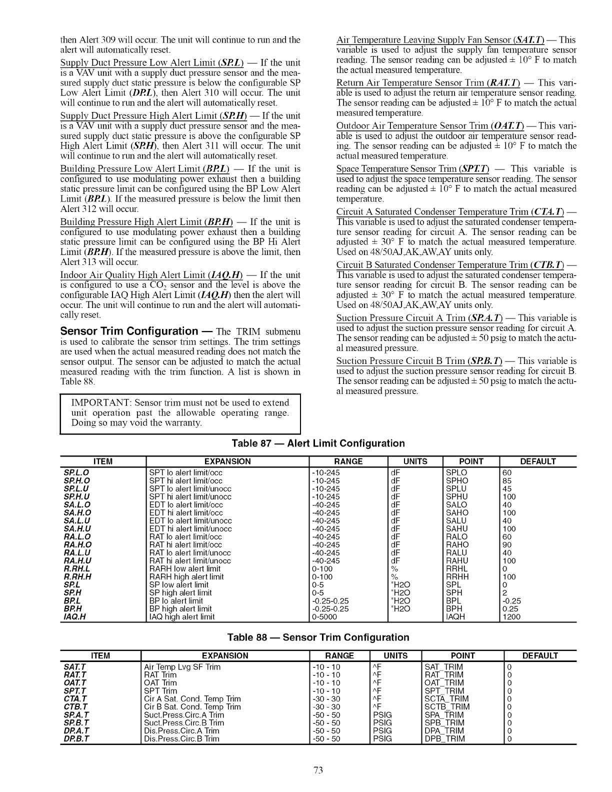
thenAlert309willoccur.Theunitwillcontinuetorunandthe
alertwillautomaticallyreset.
Supply Duct Pressure Low Alert Limit (SRL) -- If the unit
is a VAV unit with a supply duct pressure sensor and the mea-
sured supply duct static pressure is below the configurable SP
Low Alert Limit (DRL), then Alert 310 will occur. The unit
will continue to run and the alert will automatically reset.
Supply Duct Pressure High Alert Limit (SRH) -- If the unit
is a VAV unit with a supply duct pressure sensor and the mea-
sured supply duct static pressure is above the configurable SP
High Alert Limit (SRH), then Alert 311 will occur. The unit
will continue to run and the alert will automatically reset.
Building Pressure Low Alert Limit (BRL) -- If the unit is
configured to use modulating power exhaust then a building
static pressure limit can be configured using the BP Low Alert
Limit (BRL). If the measured pressure is below the limit then
Alert 312 will occur.
Building Pressure High Alert Limit (BRIg) -- If the unit is
configured to use modulating power exhaust then a building
static pressure limit can be configured using the BP Hi Alert
Lilnit (BRIg). If the measured pressure is above the lilnit, then
Alert 313 will occur.
Indoor Air Quality High Alert Limit (//1(2.[1) -- If the unit
is configured to use a CO2 sensor and the level is above the
configurable IAQ High Alert Lilnit (IAQ.H) then the alert will
occur. The unit will continue to run and the alert will automati-
cally reset.
Sensor Trim Configuration EThe TRIM submenu
is used to calibrate the sensor triln settings. The triln settings
are used when the actual measured reading does not match the
sensor output. The sensor can be adjusted to match the actual
measured reading with the trim function. A list is shown in
Table 88.
IMPORTANT: Sensor trim must not be used to extend
unit operation past the allowable operating range.
Doing so may void the warranty.
Air Temperature Leaving Supply Fan Sensor (SAT.T) -- This
variable is used to adjust the supply fan temperature sensor
reading. The sensor reading can be adjusted 4- 10oF to match
the actual measured temperature.
Return Air Temperature Sensor Trim (RAT.T) -- This vari-
able is used to adjust the return air temperature sensor reading.
The sensor reading can be adjusted 4- 10oF to match the actual
measured temperature.
Outdoor Air Temperature Sensor Trim (OAT. T) --This vari-
able is used to adjust the outdoor air temperature sensor read-
ing. The sensor reading can be adjusted 4- 10oF to match the
actual measured temperature.
Space Temperature Sensor Trim (SPT.T) -- This variable is
used to adjust the space temperature sensor reading. The sensor
reading can be adjusted 4- 10oF to match the actual measured
temperature.
Circuit A Saturated Condenser Temperature Trim (CTA. T) --
This variable is used to adjust the saturated condenser tempera-
ture sensor reading for circuit A. The sensor reading can be
adjusted 4- 30°F to match the actual measured temperature.
Used on 48/50AJ,AK,AW, AY units only.
Circuit B Saturated Condenser Temperature Trim (CTB. T) --
This variable is used to adjust the saturated condenser tempera-
ture sensor reading for circuit B. The sensor reading can be
adjusted 4- 30°F to match the actual measured temperature.
Used on 48/50AJ,AK,AW, AY units only.
Suction Pressure Circuit A Trim (SRA. T) -- This variable is
used to adjust the suction pressure sensor reading for circuit A.
The sensor reading can be adjusted 4- 50 psig to match the actu-
al measured pressure.
Suction Pressure Circuit B Trim (SRB. T) -- This variable is
used to adjust the suction pressure sensor reading for circuit B.
The sensor reading can be adjusted 4- 50 psig to match the actu-
al measured pressure.
Table 87 -- Alert Limit Configuration
ITEM
SP.L.O
SP.H.O
SP.L.U
SP.H.U
SA.L.O
SA.H.O
SA.L.U
SA.H.U
RA.L.O
RA.H.O
RA.L.U
RA.H.U
R.RH.L
R.RH.H
SP.L
SP.H
BP.L
BP.H
IAQ.H
EXPANSION
SPT Io alert limit/occ
SPT hi alert limit/occ
SPT Io alert limit/unocc
SPT hi alert limit/unocc
EDT Io alert limit/occ
EDT hi alert limit/occ
EDT Io alert limit/unocc
EDT hi alert limit/unocc
RANGE
-10-245
-10-245
-10-245
-10-245
-40-245
-40-245
-40-245
-40-245
dF
dF
dF
dF
dF
dF
dF
dF
UNITS DEFAULTPOINT
SPLO
SPHO
SPLU
SPHU
SALO
SAHO
SALU
SAHU
RAT Io alert limit/occ
RAT hi alert limit/occ
RAT Io alert limit/unocc
RAT hi alert limit/unocc
RARH low alert limit
RARH high alert limit
SP low alert limit
SP high alert limit
BP Io alert limit
BP high alert limit
IAQ high alert limit
-40-245
-40-245
-40-245
-40-245
0-1O0
0-1O0
0-5
0-5
-0.25-0.25
-0.25-0.25
0-5000
dF
dF
dF
dF
%
%
"H20
"H20
"H20
"H20
RALO
RAHO
RALU
RAHU
RRHL
RRHH
SPL
SPH
BPL
BPH
IAQH
60
85
45
1O0
40
1O0
40
1O0
60
90
40
1O0
0
1O0
0
2
-0.25
0.25
1200
Table 88 -- Sensor Trim Configuration
ITEM
SAT.T
RAT.T
OAT.T
SPT. T
CTA. T
CTB.T
SP.A. T
SP.B.T
DP.A. T
DP.B.T
EXPANSION
Air Temp Lvg SF Trim
RAT Trim
OAT Trim
SPT Trim
Cir A Sat. Cond. Temp Trim
Cir B Sat. Cond. Temp Trim
Suct.Press.Circ.A Trim
Suct.Press.Circ.B Trim
Dis.Press.Circ.A Trim
Dis.Press.Circ.B Trim
RANGE
-10 - 10
-10 - 10
-10 - 10
-10 - 10
-30 - 30
-30 - 30
-50 - 50
-50 - 50
-50 - 50
-50 - 50
UNITS
^F
^F
^F
^F
^F
^F
PSIG
PSlG
PSlG
PSlG
POINT
SAT_TRIM
RAT_TRIM
OAT_TRIM
SPT TRIM
SCT_, TRIM
SCTB TRIM
SPA -I=RIM
SPB TRIM
DPA TRIM
DPB_TRIM
DEFAULT
0
0
0
0
0
0
0
0
0
0
73
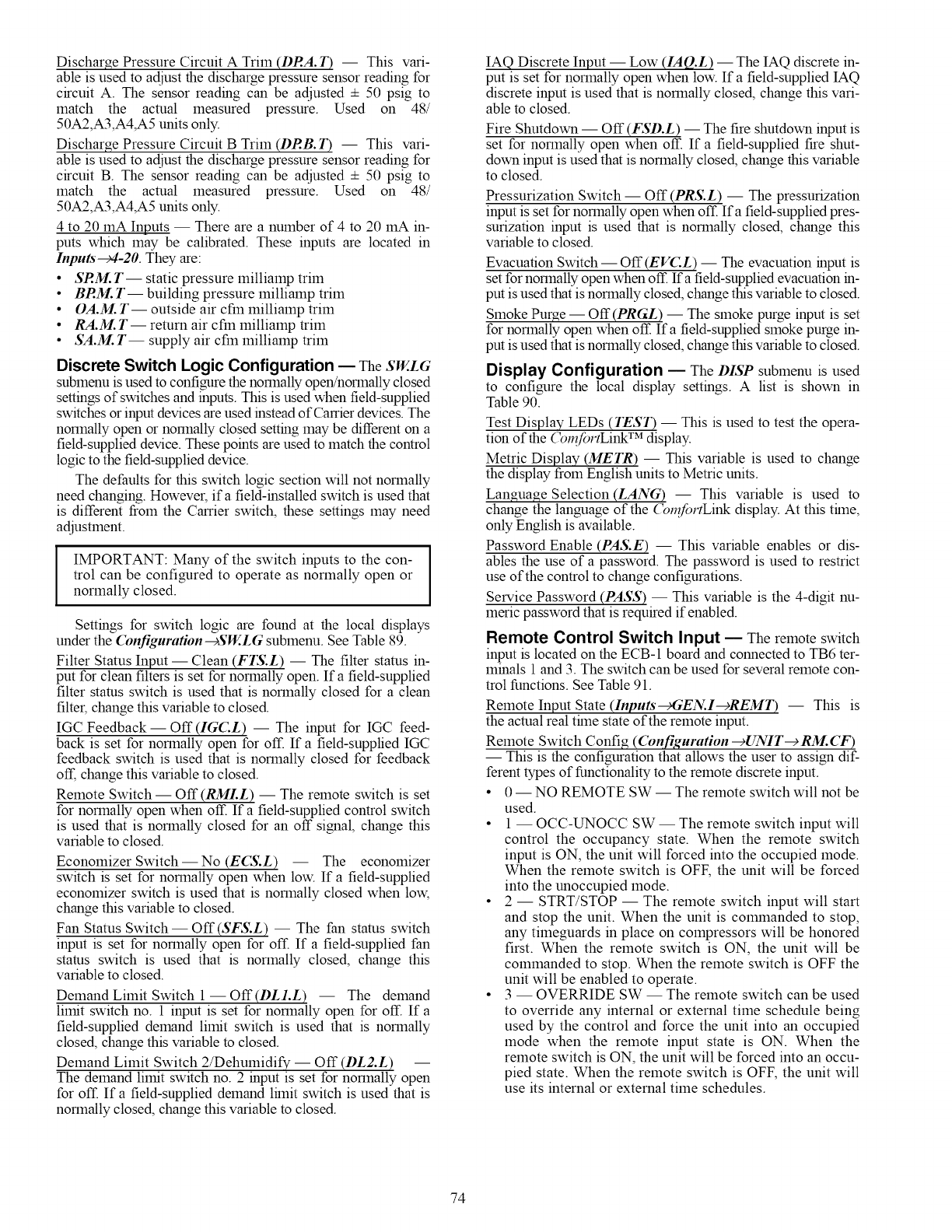
Discharge Pressure Circuit A Trim (DRA. T) -- This vari-
able is used to adjust the discharge pressure sensor reading for
circuit A. The sensor reading can be adjusted + 50 psig to
match the actual measured pressure. Used on 48/
50A2,A3,A4,A5 units only.
Discharge Pressure Circuit B Trim (DRB. T) -- This vari-
able is used to adjust the discharge pressure sensor reading for
circuit B. The sensor reading can be adjusted + 50 psig to
match the actual measured pressure. Used on 48/
50A2,A3,A4,A5 units only.
4 to 20 mA Inputs -- There are a number of 4 to 20 mA in-
puts which may be calibrated. These inputs are located in
Inputs_4-20. They are:
•SRM. T-- static pressure milliamp trim
• BRM. T-- building pressure milliamp trim
• OA.M. T-- outside air cfm milliamp trim
• RA.M. T-- return air cfm milliamp trim
• SA.M. T-- supply air cfm milliamp trim
Discrete Switch Logic Configuration EThe SW..LG
submenu is used to configure the normally open!normally closed
settings of switches and inputs. This is used when field-supplied
switches or input devices are used instead of Carrier devices. The
normally open or normally closed setting may be different on a
field-supplied device. These points are used to match the control
logic to the field-supplied device.
The defaults for this switch logic section will not normally
need changing. However, if a field-installed switch is used that
is different from the Carrier switch, these settings may need
adjustment.
IIMPORTANT: Many of the switch inputs to the con- I
I
trol can be configured to operate as normally open or I
normally closed.
Settings for switch logic are found at the local displays
under the Configuration-+SW..LG submenu. See Table 89.
Filter Status Input -- Clean (FTS.L) -- The filter stares in-
put for clean filters is set for normally open. If a field-supplied
filter stares switch is used that is normally closed for a clean
filter, change this variable to closed.
IGC Feedback- Off (IG(:L) -- The input for IGC feed-
back is set for normally open for off. If a field-supplied IGC
feedback switch is used that is normally closed for feedback
off, change this variable to closed.
Remote Switch -- Off (RMI.L) -- The remote switch is set
for normally open when off. If a field-supplied control switch
is used that is normally closed for an off signal, change this
variable to closed.
Economizer Switch -- No (ECS.L) -- The economizer
switch is set for normally open when low. If a field-supplied
economizer switch is used that is normally closed when low,
change this variable to closed.
Fan Status Switch -- Off (SFS.L) -- The fan status switch
input is set for normally open for off. If a field-supplied fan
status switch is used that is normally closed, change this
variable to closed.
Demand Limit Switch 1 -- Off (DL1.L) -- The demand
limit switch no. 1 input is set for normally open for off. If a
field-supplied demand limit switch is used that is normally
closed, change this variable to closed.
Demand Limit Switch 2/Dehumidify -- Off (DL2.L) --
The demand limit switch no. 2 input is set for normally open
for off. If a field-supplied demand lhnit switch is used that is
normally closed, change this variable to closed.
IAQ Discrete Input -- Low (IAQ.L) -- The IAQ discrete in-
put is set for normally open when low. If a field-supplied IAQ
discrete input is used that is normally closed, change this vari-
able to closed.
Fire Shutdown -- Off (FSD.L) -- The fire shutdown input is
set for normally open when off. If a field-supplied fire shut-
down input is used that is normally closed, change this variable
to closed.
Pressurization Switch -- Off (PRS.L) -- The pressurization
input is set for normally open when off. Ifa field-supplied pres-
surization input is used that is normally closed, change this
variable to closed.
Evacuation Switch -- Off (EV(:L) -- The evacuation input is
set for normally open when off. If a field-supplied evacuation in-
put is used that is normally closed, change this variable to closed.
Smoke Purge -- Off (PRGL) -- The smoke purge input is set
for normally open when off. If a field-supplied smoke purge in-
put is used that is normally closed, change this variable to closed.
Display Configuration -- The DISP submenu is used
to configure the local display settings. A list is shown in
Table 90.
Test Display LEDs (TEST) -- This is used to test the opera-
tion of the (_n_fortLink TM display.
Metric Display (METR) -- This variable is used to change
the display from English units to Metric units.
Language Selection (LANG) -- This variable is used to
change the language of the (_nfortLink display. At this tflne,
only English is available.
Password Enable (PAS.E) -- This variable enables or dis-
ables the use of a password. The password is used to restrict
use of the control to change configurations.
Service Password (PASS) -- This variable is the 4-digit nu-
meric password that is required if enabled.
Remote Control Switch Input -- The remote switch
input is located on the ECB-1 board and connected to TB6 ter-
minals 1 and 3. The switch can be used for several remote con-
trol functions. See Table 91.
Remote Input State (Inputs--gGEN.I--gREMT) -- This is
the actual real thne state of the remote input.
Remote Switch Confi g (Con.figuration --+UNIT--+ RM. CF)
-- This is the configuration that allows the user to assign dif-
ferent types of functionality to the remote discrete input.
•0 -- NO REMOTE SW -- The remote switch will not be
used.
•1 -- OCC-UNOCC SW -- The remote switch input will
control the occupancy state. When the remote switch
input is ON, the unit will forced into the occupied mode.
When the remote switch is OFF, the unit will be forced
into the unoccupied mode.
•2 -- STRT/STOP -- The remote switch input will start
and stop the unit. When the unit is colmnanded to stop,
any timeguards in place on compressors will be honored
first. When the remote switch is ON, the unit will be
commanded to stop. When the remote switch is OFF the
unit will be enabled to operate.
•3 -- OVERRIDE SW -- The remote switch can be used
to override any internal or external time schedule being
used by the control and force the unit into an occupied
mode when the remote input state is ON. When the
remote switch is ON, the unit will be forced into an occu-
pied state. When the remote switch is OFF, the unit will
use its internal or external time schedules.
74
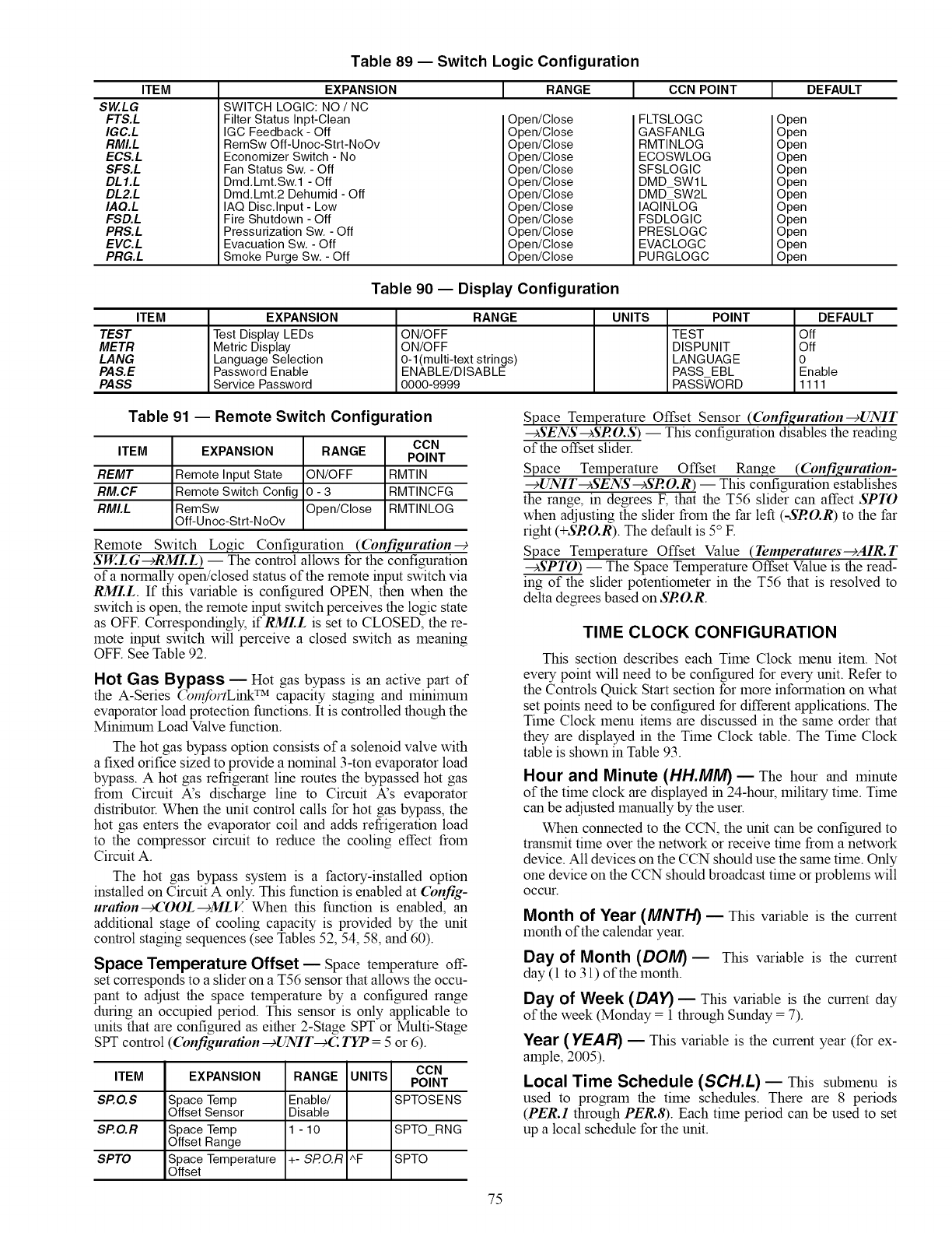
ITEM
SW.LG
FTS.L
IGC.L
RMI.L
ECS.L
SFS.L
DL1.L
DL2.L
IAQ.L
FSD.L
PRS. L
EVC.L
PRG.L
Table 89 -- Switch Logic Configuration
EXPANSION
SWITCH LOGIC: NO /NC
Filter Status Inpt-Clean
IGC Feedback - Off
RemSw Off-Unoc-Strt-NoOv
Economizer Switch - No
Fan Status Sw, - Off
Dmd,Lmt,Sw,1 - Off
Dmd,Lmt,2 Dehumid - Off
IAQ Disc, Input - Low
Fire Shutdown - Off
Pressurization Sw, - Off
Evacuation Sw, - Off
Smoke Purge Sw, - Off
[ RANGE 1 CCNPOINT [ DEFAU_
Open/Close
Open/Close
Open/Close
Open/Close
Open/Close
Open/Close
Open/Close
Open/Close
Open/Close
Open/Close
Open/Close
Open/Close
FLTSLOGC
GASFANLG
RMTINLOG
ECOSWLOG
SFSLOGIC
DMD SWl L
DMD SW2L
IAQINLOG
FSDLOGIC
PRESLOGC
EVACLOGC
PURGLOGC
Open
Open
Open
Open
Open
Open
Open
Open
Open
Open
Open
Open
Table 90 -- Display Configuration
ITEM EXPANSION RANGE UNITS POINT DEFAULT
TEST Test Display LEDs ON/OFF TEST Off
METR Metric Display ON/OFF DISPUNIT Off
LANG Language Selection O-l(multi-text strings) LANGUAGE 0
PAS.E Password Enable ENABLE/DISABLE PASS EBL Enable
PASS Service Password 0000-9999 PASS_/ORD 1111
Table 91 -- Remote Switch Configuration
CCN
ITEM EXPANSION RANGE POINT
REMT Remote Input State ON/OFF RMTIN
RM.CF Remote Switch Config 0 - 3 RMTINCFG
RMI.L RemSw Open/Close RMTINLOG
Off-Unoc-Strt-NoOv
Remote Switch Logic Configuration ((bqfiguration--€
SW..LG--cRMI.L) -- The control allows for the configuration
of a normally open!closed status of the remote input switch via
RMLL. If this variable is configured OPEN, then when the
switch is open, the remote input switch perceives the logic state
as OFF. Correspondingly, ifRMLL is set to CLOSED, the re-
mote input switch will perceive a closed switch as meaning
OFF. See Table 92.
Hot Gas Bypass EHot gas bypass is an active part of
the A-Series (_nfortLink TM capacity staging and minimum
evaporator load protection functions. It is controlled though the
Minhnum Load Valve function.
The hot gas bypass option consists of a solenoid valve with
a fixed orifice sized to provide a nominal 3-ton evaporator load
bypass. A hot gas refrigerant line routes the bypassed hot gas
from Circuit A's discharge line to Circuit A's evaporator
distributor. When the unit control calls for hot gas bypass, the
hot gas enters the evaporator coil and adds refrigeration load
to the compressor circuit to reduce the cooling effect from
Circuit A.
The hot gas bypass system is a factory-installed option
installed on Circuit A only. This function is enabled at Config-
urafion_COOL---_MLV. When this function is enabled, an
additional stage of cooling capacity is provided by the unit
control staging sequences (see Tables 52, 54, 58, and 60).
Space Temperature Offset ESpace temperature off-
set corresponds to a slider on a T56 sensor that allows the occu-
pant to adjust the space temperature by a configured range
during an occupied period. This sensor is only applicable to
units that are configured as either 2-Stage SPT or Multi-Stage
SPT control ((bnfigurafion -+UNIT-€C TYP = 5 or 6).
ITEM
SP.O.S
SP.O.R
SPTO
EXPANSION RANGE UNITS CCN
POINT
Space Temp Enable/ SPTOSENS
Offset Sensor Disable
Space Temp 1 - 10 SPTO_RNG
Offset Range
Space Temperature +- SRO.R ^F SPTO
Offset
Space Temperature Offset Sensor ((bnfiguration--cUNIT
--¢SENS--cSRO.S) -- This configuration disables the reading
of the offset slider.
Space Temperature Offset Range ((bnfiguration-
--+UNIT--+SENS--+SRO.R). -- This configuration establishes
the range, in degrees E that the T56 slider can affect SPTO
when adjusting the slider from the far left (-SRO.R) to the far
right (+SRO.R). The default is 5° E
Space Temperature Offset Value (Temperatures-+AIR.T
--+SPTO) -- The Space Temperature Offset Value is the read-
ing of the slider potentiometer in the T56 that is resolved to
delta degrees based on SRO.R.
TIME CLOCK CONFIGURATION
This section describes each Time Clock menu item. Not
every point will need to be configured for every unit. Refer to
the Controls Quick Start section for more information on what
set points need to be configured for different applications. The
Time Clock menu items are discussed in the same order that
they are displayed in the Time Clock table. The Time Clock
table is shown in Table 93.
Hour and Minute (HH.MM)_ The hour and minute
of the time clock are displayed in 24-hour, military time. Time
can be adjusted manually by the user.
When connected to the CCN, the unit can be configured to
transmit time over the network or receive time from a network
device. All devices on the CCN should use the same time. Only
one device on the CCN should broadcast time or problems will
occur.
Month of Year (MNTH) _This variable is the current
month of the calendar year.
Day of Month (DOll4)_ This variable is the current
day (1 to 31) of the month.
Day of Week (DAY) _This variable is the current day
of the week (Monday = 1 through Sunday = 7).
Year (YEAR) _This variable is the current year (for ex-
ample, 2005).
Local Time Schedule (SCH.L) _This submenu is
used to program the time schedules. There are 8 periods
(PER.1 through PER.8). Each time period can be used to set
up a local schedule for the unit.
75
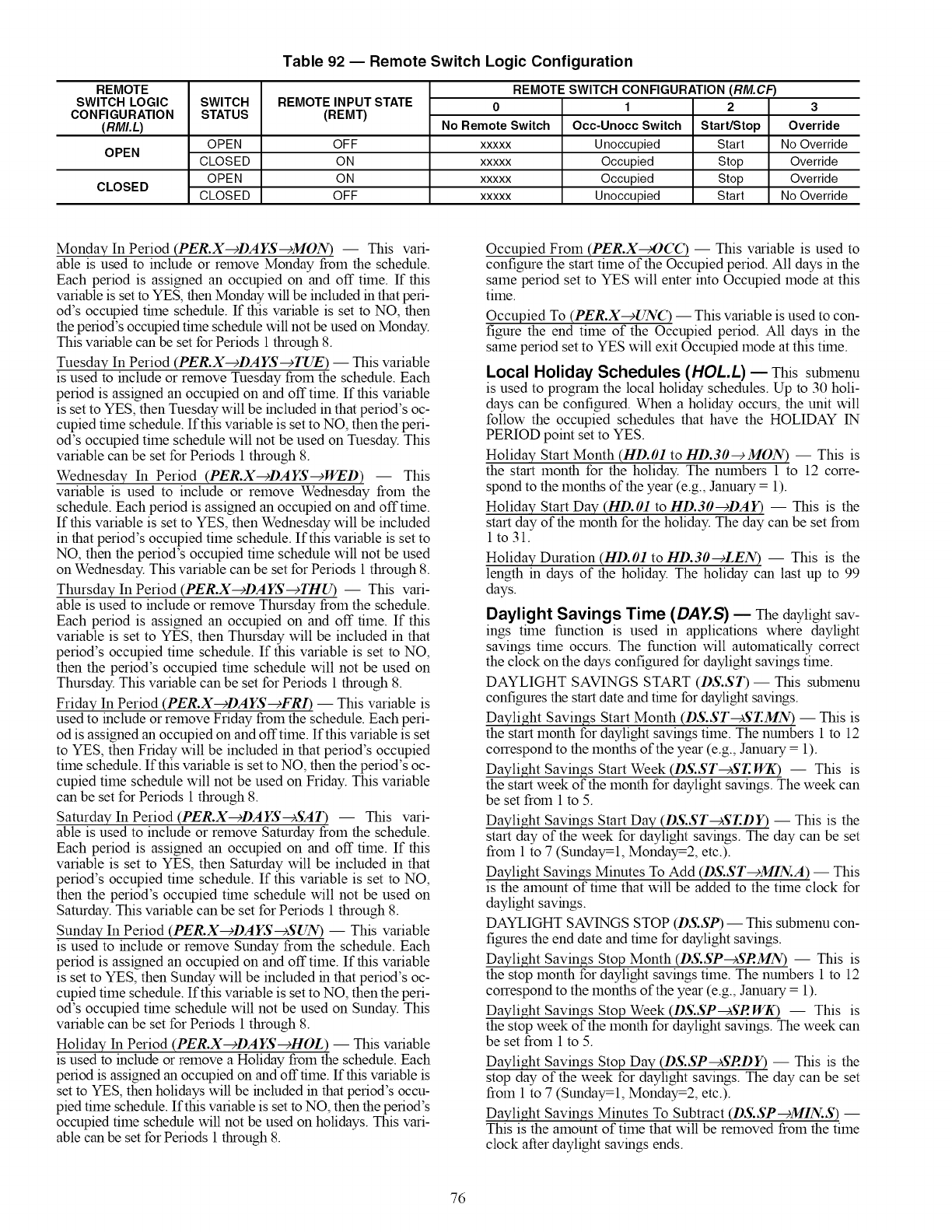
REMOTE
SWITCH LOGIC
CONFIGURATION
(RMI.L)
Table 92 -- Remote Switch Logic Configuration
SWITCH
STATUS REMOTE INPUT STATE
(REMT)
OPEN OFF
OPEN CLOSED ON
OPEN ON
CLOSED CLOSED OFF
REMOTE SWITCH CONFIGURATION (RM.CF)
No Remote Switch
XXXXX
XXXXX
XXXXX
XXXXX
1
Occ-Unocc Switch
Unoccupied
Occupied
Occupied
Unoccupied
2
Start/Stop
Start
Stop
Stop
Start
3
Override
No Override
Override
Override
No Override
Monday In Period (PER.X---_I)AYS---_MON) -- This vari-
able is used to include or remove Monday from the schedule.
Each period is assigned an occupied on and off tflne. If this
variable is set to YES, then Monday will be included in that peri-
od's occupied tflne schedule. If this variable is set to NO, then
the period's occupied time schedule will not be used on Monday.
This variable can be set for Periods 1 through 8.
Tuesday In Period (PER.X---_DAYS--_TUE) -- This variable
is used to include or remove Tuesday from the schedule. Each
period is assigned an occupied on and off time. If this variable
is set to YES, then Tuesday will be included in that period's oc-
cupied time schedule. If this variable is set to NO, then the peri-
od's occupied time schedule will not be used on Tuesday. This
variable can be set for Periods 1 through 8.
Wednesday In Period (PER.X---_I)AYS--_WED) -- This
variable is used to include or remove Wednesday from the
schedule. Each period is assigned an occupied on and offtflne.
If this variable is set to YES, then Wednesday will be included
in that period's occupied time schedule. If this variable is set to
NO, then the period's occupied time schedule will not be used
on Wednesday. This variable can be set for Periods 1 through 8.
Thursday In Period (PER.X--_DAYS--_THU) -- This vari-
able is used to include or remove Thursday from the schedule.
Each period is assigned an occupied on and off time. If this
variable is set to YES, then Thursday will be included in that
period's occupied time schedule. If this variable is set to NO,
then the period's occupied thne schedule will not be used on
Thursday. This variable can be set for Periods 1through 8.
Friday In Period (PER.X-cDAYS-cFRI) -- This variable is
used to include or remove Friday from the schedule. Each peri-
od is assigned an occupied on and offtime. If this variable is set
to YES, then Friday will be included in that period's occupied
time schedule. If this variable is set to NO, then the period's oc-
cupied time schedule will not be used on Friday. This variable
can be set for Periods 1through 8.
Saturday In Period (PER.X-cDAYS-cSA13 -- This vari-
able is used to include or remove Saturday from the schedule.
Each period is assigned an occupied on and off time. If this
variable is set to YES, then Saturday will be included in that
period's occupied time schedule. If this variable is set to NO,
then the period's occupied thne schedule will not be used on
Saturday. This variable can be set for Periods 1through 8.
Sunday In Period (PER.X-cDAYS-cSUN) -- This variable
is used to include or remove Sunday from the schedule. Each
period is assigned an occupied on and off time. If this variable
is set to YES, then Sunday will be included in that period's oc-
cupied time schedule. If this variable is set to NO, then the peri-
od's occupied thne schedule will not be used on Sunday. This
variable can be set for Periods 1through 8.
Holiday In Period (PER.X-cDAYS-cHOL) -- This variable
is used to include or remove a Holiday from the schedule. Each
period is assigned an occupied on and offtime. If this variable is
set to YES, then holidays will be included in that period's occu-
pied time schedule. If this variable is set to NO, then the period's
occupied time schedule will not be used on holidays. This vari-
able can be set for Periods 1through 8.
Occupied From (PER.X_OCC) -- This variable is used to
configure the start time of the Occupied period. All days in the
same period set to YES will enter into Occupied mode at this
time.
Occupied To (PER.X-->UNC) -- This variable isused to con-
figure the end time of the Occupied period. All days in the
same period set to YES will exit Occupied mode at this time.
Local Holiday Schedules (HOL.L) EThis submenu
is used to program the local holiday schedules. Up to 30 holi-
days can be configured. When a holiday occurs, the unit will
follow the occupied schedules that have the HOLIDAY 1N
PERIOD point set to YES.
Holiday Start Month (HD.O1 to HD.30--cMON) -- This is
the start month for the holiday. The numbers 1 to 12 corre-
spond to the months of the year (e.g., January = 1).
Holiday Start Day (HD.O1 to HD.30-cDAY) --This is the
start day of the month for the holiday. The day can be set from
1 to31.
Holiday Duration (HD.O1 to HD.30-+LEN) -- This is the
length in days of the holiday. The holiday can last up to 99
days.
Daylight Savings Time (DAY.S) _ The daylight sav-
ings time function is used in applications where daylight
savings time occurs. The function will automatically correct
the clock on the days configured for daylight savings time.
DAYLIGHT SAVINGS START (DS.ST) -- This submenu
configures the start date and time for daylight savings.
Daylight Savings Start Month (DS.ST---)ST.MN) -- This is
the start month for daylight savings time. The numbers 1 to 12
correspond to the months of the year (e.g., January = 1).
Daylight Savings Start Week (DS.ST---)ST. WK) -- This is
the start week of the month for daylight savings. The week can
be set from 1 to 5.
Daylight Savings Start Day (DS.ST--)ST.DY) -- This is the
start day of the week for daylight savings. The day can be set
from 1 to 7 (Sunday=l, Monday=2, etc.).
Daylight Savings Minutes To Add (DS.ST-cMIN.A) -- This
is the amount of time that will be added to the time clock for
daylight savings.
DAYLIGHT SAVINGS STOP (DS.SP) -- This submenu con-
figures the end date and time for daylight savings.
Daylight Savings Stop Month (DS.SP-cSRMN) -- This is
the stop month for daylight savings time. The numbers 1 to 12
correspond to the months of the year (e.g., January = 1).
Daylight Savings Stop Week (DS.SP-cSR Wit3 -- This is
the stop week of the month for daylight savings. The week can
be set from 1 to 5.
Daylight Savings Stop Day (DS.SP-cSRDY) -- This is the
stop day of the week for daylight savings. The day can be set
from 1 to 7 (Sunday=l, Monday=2, etc.).
Daylight Savings Minutes To Subtract (DS.SP-cMIN.S) --
This is the amount of time that will be removed from the time
clock after daylight savings ends.
76
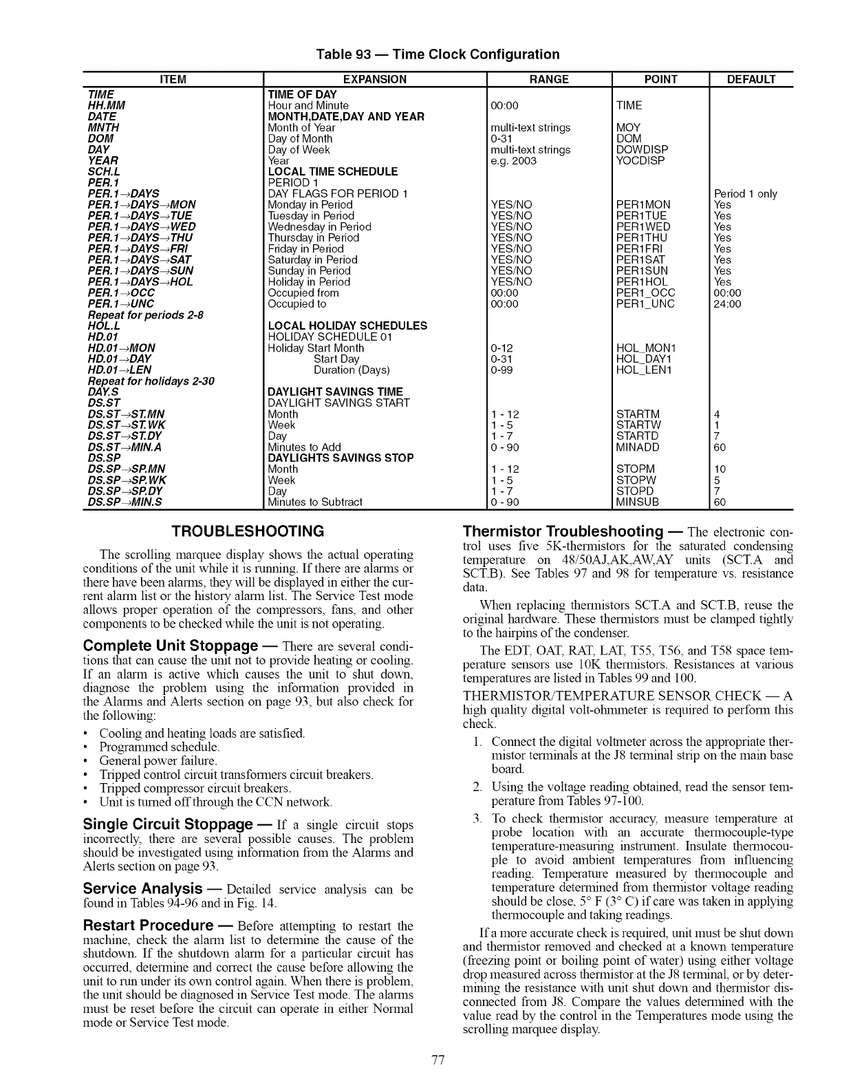
ITEM
TIME
HH.MM
DATE
MNTH
DOM
DAY
YEAR
SCH.L
PER. 1
PER. 1-_DA YS
PER. 1-_DA YS-_MON
PER.1 -_DA YS-_ TUE
PER. 1-_DAYS-_WED
PER.1 -_DA YS-_ THU
PER. 1-_DA YS-_FRI
PER. 1-_DA YS-_SA T
PER. 1-_DA YS-_SUN
PER. 1-_DA YS-_HOL
PER. 1-_OCC
PER. 1-_UNC
Repeat for periods 2-8
HOL.L
HD.01
HD.OI-_MON
HD.01 -_DAY
HD.OI-_LEN
Repeat for holidays 2-30
DAES
DS.ST
DS.ST-_ST.MN
DS.ST-_ST. WK
DS.ST-_SEDY
DS.ST-_MIN.A
DS.SP
DS.SP-_SP.MN
DS.SP-_SP. WK
DS.SP-_SP.DY
DS.SP-_MIN.S
Table 93 -- Time Clock Configuration
EXPANSION
TIME OF DAY
Hour and Minute
MONTH,DATE,DAY AND YEAR
Month of Year
Day of Month
Day of Week
Year
LOCAL TIME SCHEDULE
PERIOD 1
DAY FLAGS FOR PERIOD 1
Monday in Period
Tuesday in Period
Wednesday in Period
Thursday in Period
Friday in Period
Saturday in Period
Sunday in Period
Holiday in Period
Occupied from
Occupied to
LOCAL HOLIDAY SCHEDULES
HOLIDAY SCHEDULE 01
Holiday Start Month
Start Day
Duration (Days)
DAYLIGHT SAVINGS TIME
DAYLIGHT SAVINGS START
Month
Week
Day
Minutes to Add
DAYLIGHTS SAVINGS STOP
Month
Week
Day
Minutes to Subtract
RANGE POINT DEFAULT
00:00
multi-text strings
0-31
multi-text strings
e,g, 2003
YES/NO
YES/NO
YES/NO
YES/NO
YES/NO
YES/NO
YES/NO
YES/NO
00:00
00:00
0-12
0-31
0 -99
1 -12
1-5
1-7
0 - 90
1 -12
1-5
1-7
0 - 90
TIME
MOY
DOM
DOWDISP
YOCDISP
PER1MON
PER1TUE
PERlWED
PER1THU
PER1FRI
PER1SAT
PER1SUN
PER1HOL
PER10CC
PER1 UNC
HOL_MON1
HOL_DAY1
HOL_LEN1
STARTM
STARTW
STARTD
MINADD
STOPM
STO PW
STOPD
MINSUB
Period 1 only
Yes
Yes
Yes
Yes
Yes
Yes
Yes
Yes
00:00
24:00
4
1
7
6O
10
5
7
6O
TROUBLESHOOTING
The scrolling marquee display shows the actual operating
conditions of the unit while it is running. If there are alarms or
there have been alarms, they will be displayed in either the cur-
rent alarm list or the history alarm list. The Service Test mode
allows proper operation of the compressors, fans, and other
components to be checked while the unit is not operating.
Complete Unit Stoppage -- There are several condi-
tions that can cause the unit not to provide heating or cooling.
If an alarm is active which causes the unit to shut down,
diagnose the problem using the information provided in
the Alarms and Alerts section on page 93, but also check for
the following:
• Cooling and heating loads are satisfied.
•Progralraned schedule.
• General power failure.
• Tripped control circuit transformers circuit breakers.
• Tripped compressor circuit breakers.
• Unit is turned offthrough the CCN network.
Single Circuit Stoppage -- If a single circuit stops
incorrectly, there are several possible causes. The problem
should be investigated using information from the Alarms and
Alerts section on page 93.
Service Analysis- Detailed service analysis can be
found in Tables 94-96 and in Fig. 14.
Restart Procedure -- Before attempting to restart the
machine, check the alarm list to determine the cause of the
shutdown. If the shutdown alarm for a particular circuit has
occurred, determine and correct the cause before allowing the
unit to run under its own control again. When there is problem,
the unit should be diagnosed in Service Test mode. The alarms
must be reset before the circuit can operate in either Normal
mode or Service Test mode.
Thermistor Troubleshooting -- The electronic con-
trol uses five 5K-thermistors for the saturated condensing
temperature on 48/50AJ,AK,AW, AY units (SCT.A and
SCT.B). See Tables 97 and 98 for temperature vs. resistance
data.
When replacing thermistors SCT.A and SCT.B, reuse the
original hardware. These thermistors must be clamped tightly
to the hairpins of the condenser.
The EDT, OAT, RAT, LAT, T55, T56, and T58 space tem-
perature sensors use 10K thermistors. Resistances at various
temperatures are listed in Tables 99 and 100.
THERMISTOR/TEMPERATURE SENSOR CHECK -- A
high quality digital volt-ohiraneter is required to perform this
check.
1. Connect the digital voltmeter across the appropriate ther-
mistor terminals at the J8 terminal strip on the main base
board.
2. Using the voltage reading obtained, read the sensor tem-
perature from Tables 97-100.
3. To check thermistor accuracy, measure temperature at
probe location with an accurate thermocouple-type
temperature-measuring instrument. Insulate thermocou-
ple to avoid ambient temperatures from influencing
reading. Temperature measured by thermocouple and
temperature determined from thermistor voltage reading
should be close, 5° F (3 ° C) if care was taken in applying
thermocouple and taking readings.
Ifa more accurate check is required, unit must be shut down
and thermistor removed and checked at a known temperature
(freezing point or boiling point of water) using either voltage
drop measured across thermistor at the J8 terminal, or by deter-
mining the resistance with unit shut down and thermistor dis-
connected from J8. Compare the values determined with the
value read by the control in the Temperatures mode using the
scrolling marquee display.
77
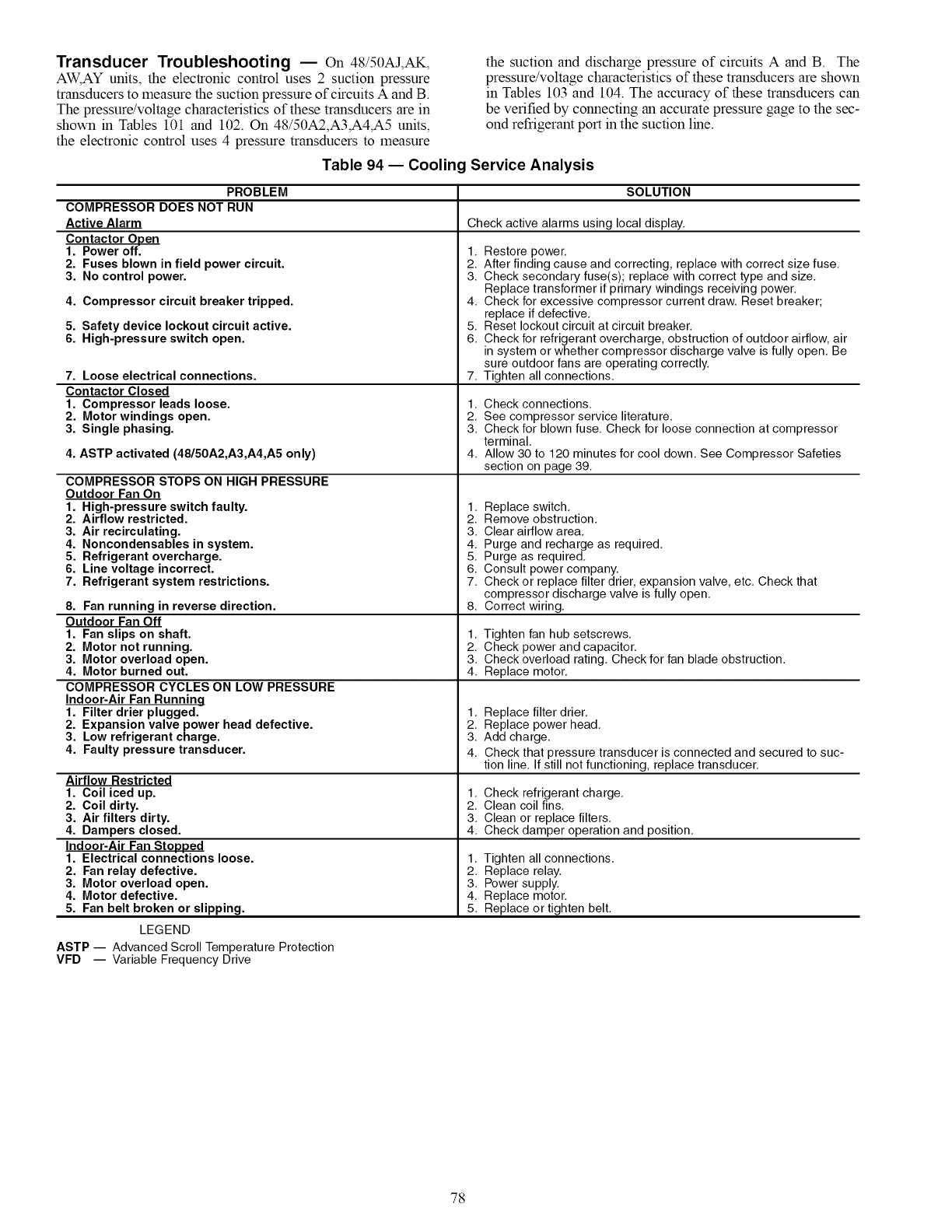
Transducer Troubleshooting EOn 48/50AJ,AK,
AW, AY units, the electronic control uses 2 suction pressure
transducers to measure the suction pressure of circuits A and B.
The pressure/voltage characteristics of these transducers are in
shown in Tables 101 and 102. On 48/50A2,A3,A4,A5 units,
the electronic control uses 4 pressure transducers to measure
the suction and discharge pressure of circuits A and B. The
pressure/voltage characteristics of these transducers are shown
in Tables 103 and 104. The accuracy of these transducers can
be verified by connecting an accurate pressure gage to the sec-
ond refrigerant port in the suction line.
Table 94 -- Cooling Service Analysis
PROBLEM
COMPRESSOR DOES NOT RUN
Active Alarm
Contactor Open
1. Power off. 1.
2. Fuses blown in field power circuit. 2.
3. No control power. 3.
4. Compressor circuit breaker tripped. 4.
5. Safety device lockout circuit active. 5.
6. High-pressure switch open. 6.
7. Loose electrical connections. 7.
Contactor Closed
1. Compressor leads loose. 1.
2. Motor windings open. 2.
3. Single phasing. 3.
4. ASTP activated (48/50A2,A3,A4,A5 only) 4.
COMPRESSOR STOPS ON HIGH PRESSURE
Outdoor Fan On
1. High-pressure switch faulty. 1.
2. Airflow restricted. 2.
3. Air recirculating. 3.
4. Noncondensables in system. 4.
5. Refrigerant overcharge. 5.
6. Line voltage incorrect. 6.
7. Refrigerant system restrictions. 7.
8. Fan running in reverse direction. 8.
Outdoor Fan Off
1. Fan slips on shaft. 1.
2. Motor not running. 2.
3. Motor overload open. 3.
4. Motor burned out. 4.
COMPRESSOR CYCLES ON LOW PRESSURE
Indoor-Air Fan Running
1. Filter drier plugged. 1.
2. Expansion valve power head defective. 2.
3. Low refrigerant charge. 3.
4. Faulty pressure transducer. 4.
Airflow Restricted
1. Coil iced up.
2. Coil dirty.
3. Air filters dirty.
4. Dampers closed.
Indoor-Air Fan Stopped
1. Electrical connections loose.
2. Fan relay defective.
3. Motor overload open.
4. Motor defective.
5. Fan belt broken or slipping.
SOLUTION
Check active alarms using local display.
Restore power.
After finding cause and correcting, replace with correct size fuse.
Check secondary fuse(s); replace with correct type and size.
Replace transformer if primary windings receiving power.
Check for excessive compressor current draw. Reset breaker;
replace if defective.
Reset lockout circuit at circuit breaker.
Check for refrigerant overcharge, obstruction of outdoor airflow, air
in system or whether compressor discharge valve is fully open. Be
sure outdoor fans are operating correctly.
Tighten all connections.
Check connections.
See compressor service literature.
Check for blown fuse. Check for loose connection at compressor
terminal.
Allow 30 to 120 minutes for cool down. See Compressor Safeties
section on page 39.
Replace switch.
Remove obstruction.
Clear airflow area.
Purge and recharge as required.
Purge as required.
Consult power company.
Check or replace filter drier, expansion valve, etc. Check that
compressor discharge valve is fully open.
Correct wiring.
Tighten fan hub setscrews.
Check power and capacitor.
Check overload rating. Check for fan blade obstruction.
Replace motor.
Replace filter drier.
Replace power head.
Add charge.
Check that pressure transducer is connected and secured to suc-
tion line. If still not functioning, replace transducer.
1. Check refrigerant charge.
2. Clean coil fins.
3. Clean or replace filters.
4. Check damper operation and position.
1. Tighten all connections.
2. Replace relay.
3. Power supply.
4. Replace motor.
5. Replace or tighten belt.
LEGEND
ASTP -- Advanced Scroll Temperature Protection
VFD -- Variable Frequency Drive
78
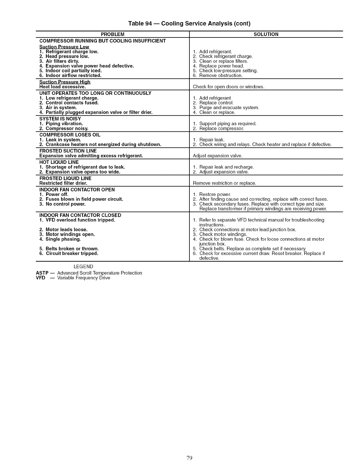
Table 94 -- Cooling Service Analysis (cont)
PROBLEM
COMPRESSOR RUNNING BUT COOLING INSUFFICIENT
Suction Pressure Low
1. Refrigerant charge low.
2. Head pressure low.
3. Air filters dirty.
4. Expansion valve power head defective.
5. Indoor coil partially iced.
6. Indoor airflow restricted.
Suction Pressure High
Heat load excessive.
UNIT OPERATES TOO LONG OR CONTINUOUSLY
1. Low refrigerant charge.
2. Control contacts fused.
3. Air in system.
4. Partially plugged expansion valve or filter drier.
SYSTEM IS NOISY
1. Piping vibration.
2. Compressor noisy.
COMPRESSOR LOSES OIL
1. Leak in system.
2. Crankcase heaters not energized during shutdown.
FROSTED SUCTION LINE
Expansion valve admitting excess refrigerant.
HOT LIQUID LINE
1. Shortage of refrigerant due to leak.
2. Expansion valve opens too wide.
FROSTED LIQUID LINE
Restricted filter drier.
INDOOR FAN CONTACTOR OPEN
1. Power off.
2. Fuses blown in field power circuit.
3. No control power.
SOLUTION
1. Add refrigerant,
2. Check refrigerant charge,
3. Clean or replace filters,
4. Replace power head,
5. Check low-pressure setting,
6. Remove obstruction,
Check for open doors or windows.
1. Add refrigerant
2. Replace control.
3. Purge and evacuate system.
4. Clean or replace.
1. Support piping as required.
2. Replace compressor.
1. Repair leak.
2. Check wiring and relays. Check heater and replace if defective.
Adjust expansion valve.
1. Repair leak and recharge.
2. Adjust expansion valve.
Remove restriction or replace.
1. Restore power.
2. After finding cause and correcting, replace with correct fuses.
3. Check secondary fuses. Replace with correct type and size.
Replace transformer if primary windings are receiving power.
INDOOR FAN CONTACTOR CLOSED
1. VFD overload function tripped. 1.
2. Motor leads loose.
3. Motor windings open.
4. Single phasing.
5. Belts broken or thrown.
6. Circuit breaker tripped.
LEGEND
ASTP -- Advanced Scroll Temperature Protection
VFD -- Variable Frequency Drive
Refer to separate VFD technical manual for troubleshooting
instructions.
2. Check connections at motor lead junction box.
3. Check motor windings.
4. Check for blown fuse. Check for loose connections at motor
junction box.
5. Check belts. Replace as complete set if necessary.
6. Check for excessive current draw. Reset breaker. Replace if
defective.
79
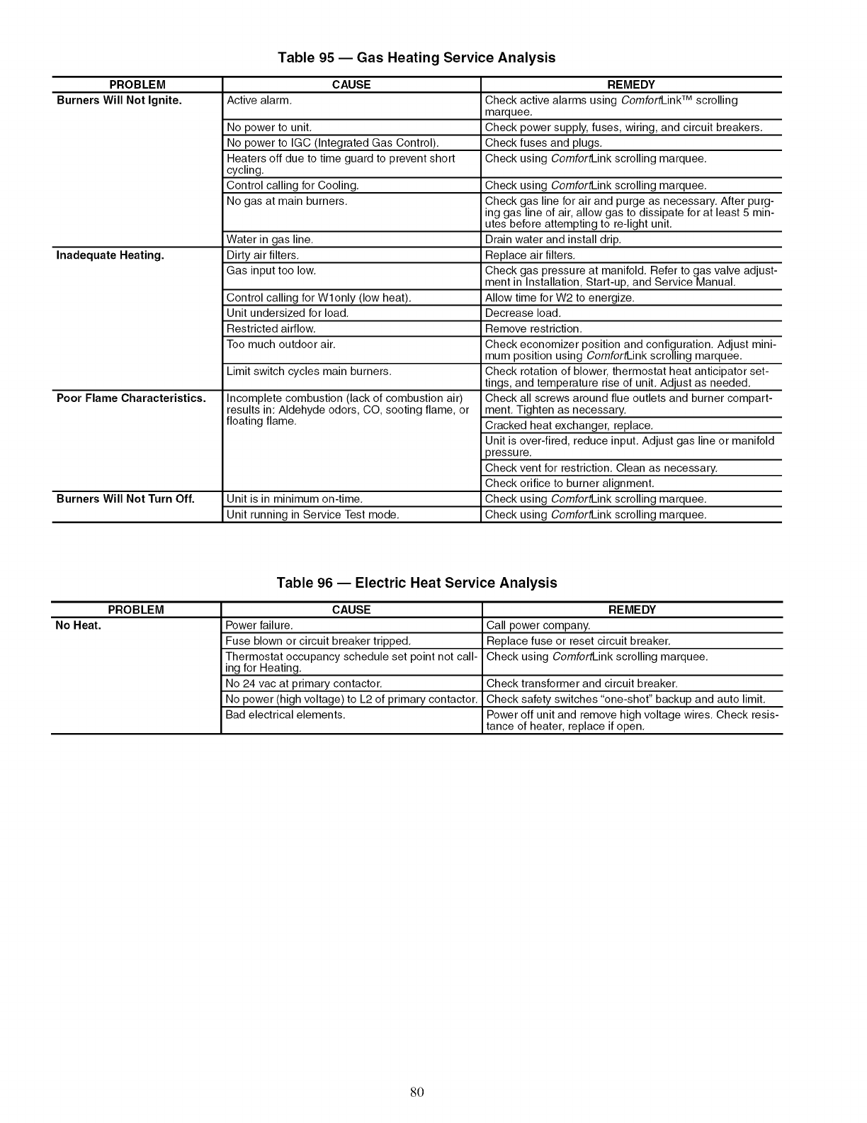
Table 95 -- Gas Heating Service Analysis
PROBLEM CAUSE REMEDY
Burners Will Not Ignite. Active alarm. Check active alarms using ComfortLink TM scrolling
marquee.
No power to unit. Check power supply, fuses, wiring, and circuit breakers.
No power to IGC (Integrated Gas Control). Check fuses and plugs.
Heaters off due to time guard to prevent short Check using ComfortLink scrolling marquee.
cycling.
Control calling for Cooling.
No gas at main burners.
Water in gas line.
Inadequate Heating. Dirty air filters.
Gas input too low.
Control calling for Wlonly (low heat).
Unit undersized for load.
Restricted airflow.
Too much outdoor air.
Limit switch cycles main burners.
Poor Flame Characteristics. Incomplete combustion (lack of combustion air)
results in: Aldehyde odors, CO, sooting flame, or
floating flame.
Burners Will Not Turn Off. Unit is in minimum on-time.
Unit running in Service Test mode.
Check using ComfortLink scrolling marquee.
Check gas line for air and purge as necessary. After purg-
ing gas line of air, allow gas to dissipate for at least 5 min-
utes before attempting to re-light unit.
Drain water and install drip.
Replace air filters.
Check gas pressure at manifold. Refer to gas valve adjust-
ment in Installation, Start-up, and Service Manual.
Allow time for W2 to energize.
Decrease load.
Remove restriction.
Check economizer position and configuration. Adjust mini-
mum position using ComfortLink scrolling marquee.
Check rotation of blower, thermostat heat anticipator set-
tings, and temperature rise of unit. Adjust as needed.
Check all screws around flue outlets and burner compart-
ment. Tighten as necessary.
Cracked heat exchanger, replace.
Unit is over-fired, reduce input. Adjust gas line or manifold
)ressure.
Check vent for restriction. Clean as necessary.
Check orifice to burner alignment.
Check using ComfortLink scrolling marquee.
Check using ComfortLink scrolling marquee.
Table 96 -- Electric Heat Service Analysis
PROBLEM CAUSE REMEDY
No Heat. Power failure. Call power company.
Fuse blown or circuit breaker tripped. Replace fuse or reset circuit breaker.
Thermostat occupancy schedule set point not call- Check using ComfortLink scrolling marquee.
ing for Heating.
No 24 vac at primary contactor. Check transformer and circuit breaker.
No power (high voltage) to L2 of primary contactor. Check safety switches "one-shot" backup and auto limit.
Bad electrical elements. Power off unit and remove high voltage wires. Check resis-
tance of heater, replace if open.
80
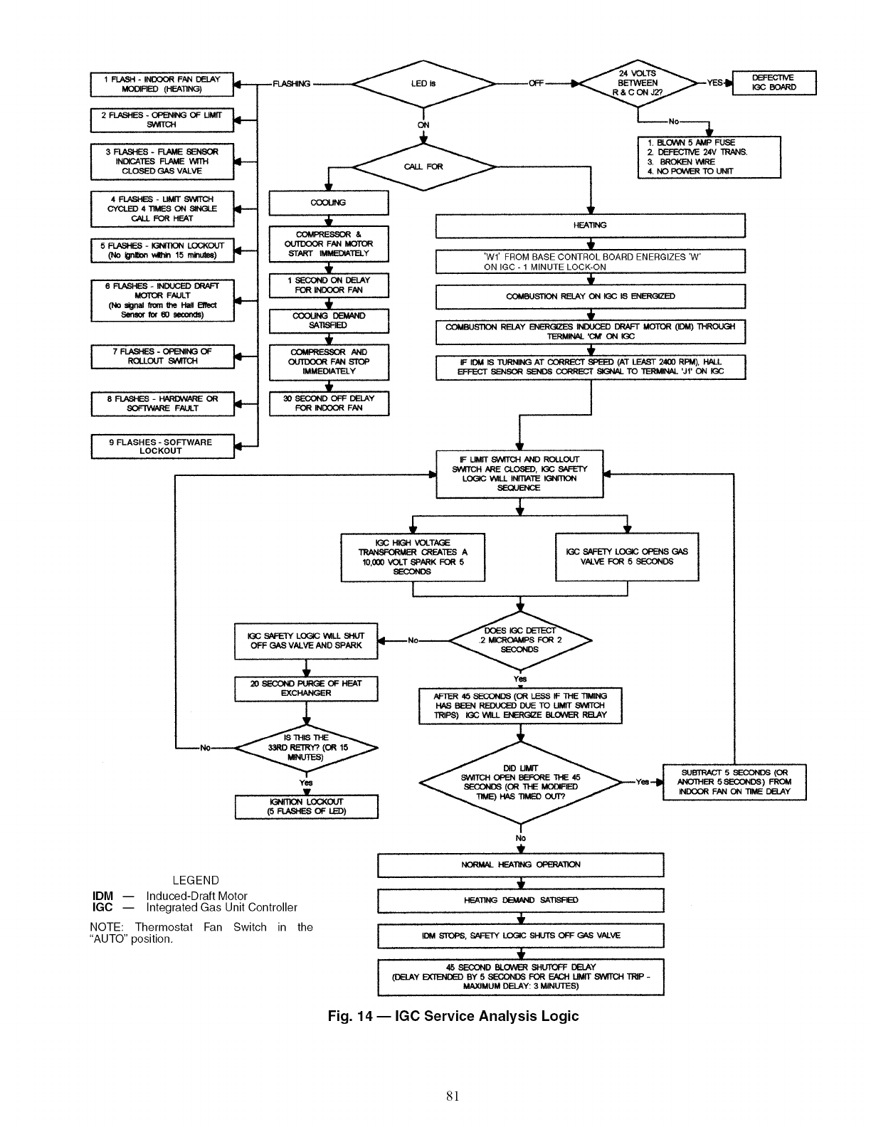
I I F_ - _ FAN DELAY I._MODPlED (HEAT_3) r-
I2FLUS - OPENk'qG OF UMIT
IN[_.,ATES _ _
CLOSED GAS VALVE
CYCLED 4 TIMES ON SINGLE
CALL FOR HEAT
(No i_aon wL_ 15 m/_ee)
/
6 FLASHES - INDUCED DRAFT /
MOTOf_ FALILT
(No _gnal from the H_J Em_ct
Sensor for eO seoor_)
7 FLASHES -_OF _I--ROLLOUT SWITCH
8 FLASHES - _OR
SOFTWARE FAULT
9 FLASHES -SOFTWARELOCKOUT
COMPRESSOR & I
_F/_I MOTOR
ST,,a_q" _TELY
I 1 SECOND ON I_LAY I
FOR INDOOR FAN
t
i_ AND I
_ F_ s'r_ I
IMME,OIATELY I
,
I I
FOR ff4l:X:X_ FAN
I
IIGC SAFETY LOGIC WILL SHUT
OFF GAS VALVE AND SPARK
4,
EXCHANGER
Yes
1' ,
I _n'_4 LC_,_cxrr t
LEGEND
IDM -- Induced-Draft Motor
IGC -- Integrated Gas Unit Controller
NOTE: Thermostat Fan Switch in the
"AUTO" position,
ON
I
I
I
1
HEATING
t
'Wf FROM BASE CONTROL BOARD ENERGIZES 'W'
ON IGC - 1 MINUTE LOCK-ON
RELAY ON IGC 18 ENERGIZED
1. BLOWN 5 _P FUSE
2. DEFECTIVE 24V TRANS.
&BROKEN '€_tRE
4. NO _TO UNIT
I COMBUSTION RELAY B_=RGI_-'_ INDUCED DRAFT MOTOR (IOM)
TEP_INAL 'Cl_ ON
t
I IF IDM iS TURNING AT CORRECT SPEED (AT L_ 2400 RPM), HN_
EFFECT SENSOR SENDS CORRECI" SIGNAL TO TERMINAL 'Jl' ON K31C
I
IF UMIT SWITCH/kND ROLLOUT
SWITCH ARE CLOSED, IGC SAFETY
LOGIC V_LL INMATE IGNmON
SEQUENCE
4, 4,
_ CRF__I_S A
10,000 VOLT SPARK FOR 5
SECONDS
I
Yes
HAS BEEN REDUCED DUE TO LIMIT,S%"_TI'(:TrlI
TRIPS) _"WILL_E BLOWIER RELAY I
IGC SAFETY LOGIC OPENS GAS
VhLVE FOR 5 SECONDS
I
No
IHEATI__ =T_ED I
I E)M STOPS, SPFETY LOGIC SHUTS OFF _V/_.VE I
, '
45 SECOND BLOW_ _LrrOFF DELAY }
(DBLAY EXTENDED BY 5 SECONDS FOR EACH LIMIT SW_TCH TRP -
MAXIMUM DELAY: 3 MINUTES)
_ 5 SECONOS(OR
ANOTHER5SECONDS)FROM
INDOORFANON TIMEDELAY
Fig. 14 -- IGC Service Analysis Logic
81
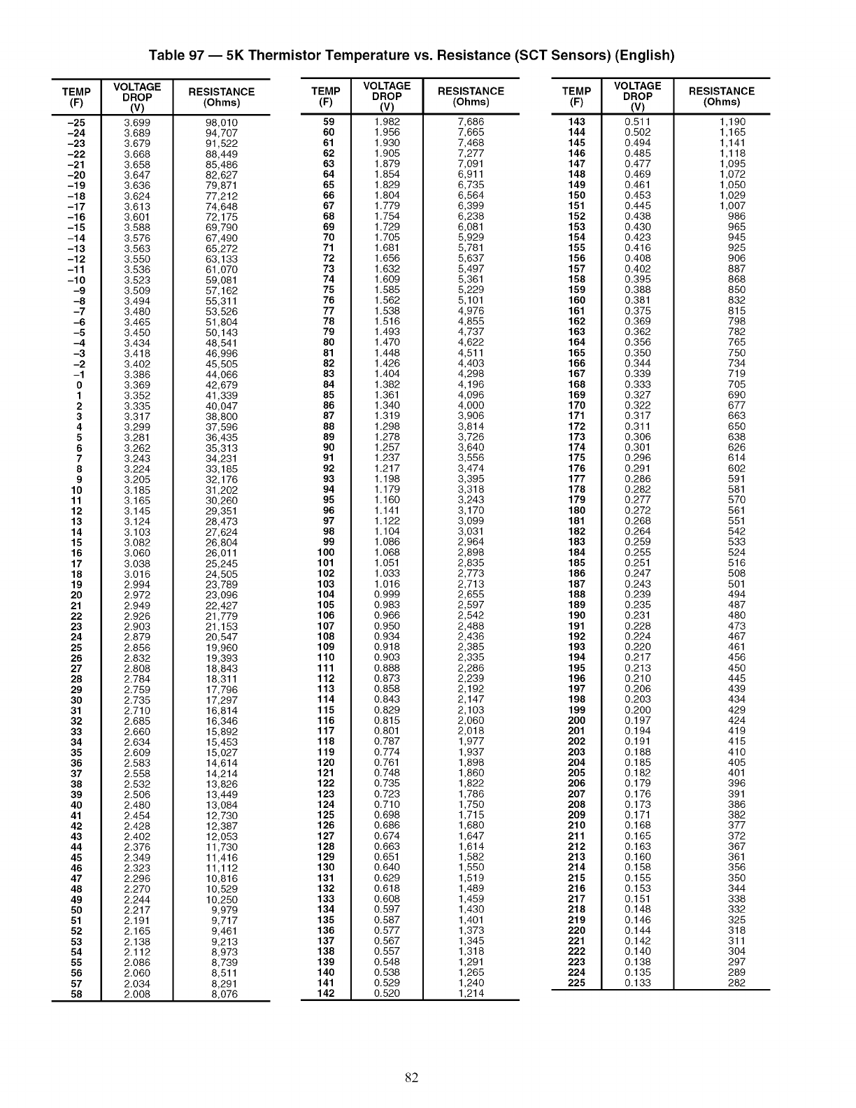
Table 97 -- 5K Thermistor Temperature vs. Resistance (SCT Sensors) (English)
TEMP RESISTANCE
(F) (Ohms)
-25
-24
-23
-22
-21
-20
-19
-18
-17
-16
-15
-14
-13
-12
-11
-10
-9
-8
-7
-6
-5
-4
-3
-2
-1
0
1
2
3
4
5
6
7
8
9
10
11
12
13
14
15
16
17
18
19
20
21
22
23
24
25
26
27
28
29
30
31
32
33
34
35
36
37
38
39
40
41
42
43
44
45
46
47
48
49
50
51
52
53
54
55
56
57
58
VOLTAGE
DROP
(v)
3.699
3.689
3.679
3.668
3.658
3.647
3.636
3.624
3.613
3.601
3.588
3.576
3.563
3.550
3.536
3.523
3.509
3.494
3.480
3.465
3.450
3.434
3.418
3.402
3.386
3.369
3.352
3.335
3.317
3.299
3.281
3.262
3.243
3.224
3.205
3.185
3.165
3.145
3.124
3.103
3.082
3.060
3.038
3.016
2.994
2.972
2.949
2.926
2.903
2.879
2.856
2.832
2.808
2.784
2.759
2.735
2.710
2.685
2.660
2.634
2.609
2.583
2.558
2.532
2.506
2.480
2.454
2.428
2.402
2.376
2.349
2.323
2.296
2.270
2.244
2.217
2.191
2.165
2.138
2.112
2.086
2.060
2.034
2.008
98,010
94,707
91,522
88,449
85,486
82,627
79,871
77,212
74,648
72,175
69,790
67,490
65,272
63,133
61,070
59,081
57,162
55,311
53,526
51,804
50,143
48,541
46,996
45,505
44,066
42,679
41,339
40,047
38,800
37,596
36,435
35,313
34,231
33,185
32,176
31,202
30,260
29,351
28,473
27,624
26,804
26,011
25,245
24,505
23,789
23,096
22,427
21,779
21,153
20,547
19,960
19,393
18,843
18,311
17,796
17,297
16,814
16,346
15,892
15,453
15,027
14,614
14,214
13,826
13,449
13,084
12,730
12,387
12,053
11,730
11,416
11,112
10,816
10,529
10,250
9,979
9,717
9,461
9,213
8,973
8,739
8,511
8,291
8,076
TEMP
(F) (V)
59 1.982
60 1.956
61 1.930
62 1.905
63 1.879
64 1.854
65 1.829
66 1.804
67 1.779
68 1.754
69 1.729
70 1.705
71 1.681
72 1.656
73 1.632
74 1.609
75 1.585
76 1.562
77 1.538
78 1.516
79 1.493
80 1.470
81 1.448
82 1.426
83 1.404
84 1.382
85 1.361
86 1.340
87 1.319
88 1.298
89 1.278
90 1.257
91 1.237
92 1.217
93 1.198
94 1.179
95 1.160
96 1.141
97 1.122
98 1.104
99 1.086
100 1.068
101 1.051
102 1.033
103 1.016
104 0.999
105 0.983
106 0.966
107 0.950
108 0.934
109 0.918
110 0.903
111 0.888
112 0.873
113 0.858
114 0.843
115 0.829
116 0.815
117 0.801
118 0.787
119 0.774
120 0.761
121 0.748
122 0.735
123 0.723
124 0.710
125 0.698
126 0.686
127 0.674
128 0.663
129 0.651
130 0.640
131 0.629
132 0.618
133 0.608
134 0.597
135 0.587
136 0.577
137 0.567
138 0.557
139 0.548
140 0.538
141 0.529
142 0.520
VOLTAGE
DROP RESISTANCE
(Ohms)
TEMP RESISTANCE
(F) (Ohms)
7,686 143
7,665 144
7,468 145
7,277 146
7,091 147
6,911 148
6,735 149
6,564 150
6,399 151
6,238 152
6,081 153
5,929 154
5,781 155
5,637 156
5,497 157
5,361 158
5,229 159
5,101 160
4,976 161
4,855 162
4,737 163
4,622 164
4,511 165
4,403 166
4,298 167
4,196 168
4,096 169
4,000 170
3,906 171
3,814 172
3,726 173
3,640 174
3,556 175
3,474 176
3,395 177
3,318 178
3,243 179
3,170 180
3,099 181
3,031 182
2,964 183
2,898 184
2,835 185
2,773 186
2,713 187
2,655 188
2,597 189
2,542 190
2,488 191
2,436 192
2,385 193
2,335 194
2,286 195
2,239 196
2,192 197
2,147 198
2,103 199
2,060 200
2,018 201
1,977 202
1,937 203
1,898 204
1,860 205
1,822 206
1,786 207
1,750 208
1,715 209
1,680 210
1,647 211
1,614 212
1,582 213
1,550 214
1,519 215
1,489 216
1,459 217
1,430 218
1,401 219
1,373 220
1,345 221
1,318 222
1,291 223
1,265 224
1,240 225
1,214
VOLTAGE
DROP
(v)
0.511
0.502
0.494
0.485
0.477
0.469
0.461
0.453
0.445
0.438
0.430
0.423
0.416
0.408
0.402
0.395
0.388
0.381
0.375
0.369
0.362
0.356
0.350
0.344
0.339
0.333
0.327
0.322
0.317
0.311
0.306
0.301
0.296
0.291
0.286
0.282
0.277
0.272
0.268
0.264
0.259
0.255
0.251
0.247
0.243
0.239
0.235
0.231
0.228
0.224
0.220
0.217
0.213
0.210
0.206
0.203
0.200
0.197
0.194
0.191
0.188
0.185
0.182
0.179
0.176
0.173
0.171
0.168
0.165
0.163
0.160
0.158
0.155
0.153
0.151
0.148
0.146
0.144
0.142
0.140
0.138
0.135
0.133
1,190
1,165
1,141
1,118
1,095
1,072
1,050
1,029
1,007
986
965
945
925
906
887
868
850
832
815
798
782
765
750
734
719
705
690
677
663
650
638
626
614
602
591
581
570
561
551
542
533
524
516
508
501
494
487
480
473
467
461
456
450
445
439
434
429
424
419
415
410
405
401
396
391
386
382
377
372
367
361
356
350
344
338
332
325
318
311
304
297
289
282
82
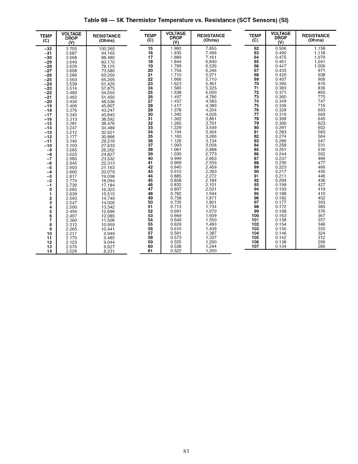
Table 98 -- 5K Thermistor Temperature vs. Resistance (SCT Sensors) (SI)
TEMP
(c)
-32
-31 3.687
-30 3.668
-29 3.649
-28 3.629
-27 3.608
-26 3.586
-25 3.563
-24 3.539
-23 3.514
-22 3.489
-21 3.462
-20 3.434
-19 3.406
-18 3.376
-17 3.345
-16 3.313
-15 3.281
-14 3.247
-13 3.212
-12 3.177
-11 3.140
-10 3.103
-9 3.065
-8 3.025
-7 2.985
-6 2.945
-5 2.903
-4 2.860
-3 2.817
-2 2.774
-1 2.730
0 2.685
1 2.639
2 2.593
3 2.547
4 2.500
5 2.454
6 2.407
7 2.360
8 2.312
9 2.265
10 2.217
11 2.170
12 2.123
13 2.076
14 2.029
VOLTAGE RESISTANCE
DROP
(V) (Ohms)
3.705
TEMP RESISTANCE
(C) (Ohms)
100,260 15
94,165 16
88,480 17
83,170 18
78,125 19
73,580 20
69,250 21
65,205 22
61,420 23
57,875 24
54,555 25
51,450 26
48,536 27
45,807 28
43,247 29
40,845 30
38,592 31
38,476 32
34,489 33
32,621 34
30,866 35
29,216 36
27,633 37
26,202 38
24,827 39
23,532 40
22,313 41
21,163 42
20,079 43
19,058 44
18,094 45
17,184 46
16,325 47
15,515 48
14,749 49
14,026 50
13,342 51
12,696 52
12,085 53
11,506 54
10,959 55
10,441 56
9,949 57
9,485 58
9,044 59
8,627 60
8,231 61
VOLTAGE
DROP
(v)
1.982
1.935
1.889
1.844
1.799
1.754
1.710
1.666
1.623
1.580
1.538
1.497
1.457
1.417
1.378
1.340
1.302
1.265
1.229
1.194
1.160
1.126
1.093
1.061
1.030
0.999
0.969
0.940
0.912
0.885
0.858
0.832
0.807
0.782
0.758
0.735
0.713
0.691
0.669
O.649
0.629
0.610
0.591
0.573
0.555
0.538
0.522
7,855
7,499
7,161
6,840
6,536
6,246
5,971
5,710
5,461
5,225
5,000
4,786
4,583
4,389
4,204
4,028
3,861
3,701
3,549
3,404
3,266
3,134
3,008
2,888
2,773
2,663
2,559
2,459
2,363
2,272
2,184
2,101
2,021
1,944
1,871
1,801
1,734
1,670
1,609
1,550
1,493
1,439
1,387
1,337
1,290
1,244
1,200
TEMP RESISTANCE
(C) (Ohms)
62
63
64
65
66
67
68
69
70
71
72
73
74
75
76
77
78
79
80
81
82
83
84
85
86
87
88
89
90
91
92
93
94
95
96
97
98
99
100
101
102
103
104
105
106
107
VOLTAGE
DROP
(v)
0.506
0.490
0.475
0.461
0.447
0.433
0.420
0.407
0.395
0.383
0.371
0.360
0.349
0.339
0.329
0.319
0.309
0.300
0.291
0.283
0.274
0.266
0.258
0.251
0.244
0.237
0.230
0.223
0.217
0.211
0.204
0.199
0.193
0.188
0.182
0.177
0.172
0.168
0.163
0.158
0.154
0.150
0.146
0.142
0.138
0.134
1,158
1,118
1,079
1,041
1,006
971
938
9O6
876
836
805
775
747
719
693
669
645
623
602
583
564
547
531
516
502
489
477
466
456
446
436
427
419
410
402
393
385
376
367
357
346
335
324
312
299
285
83
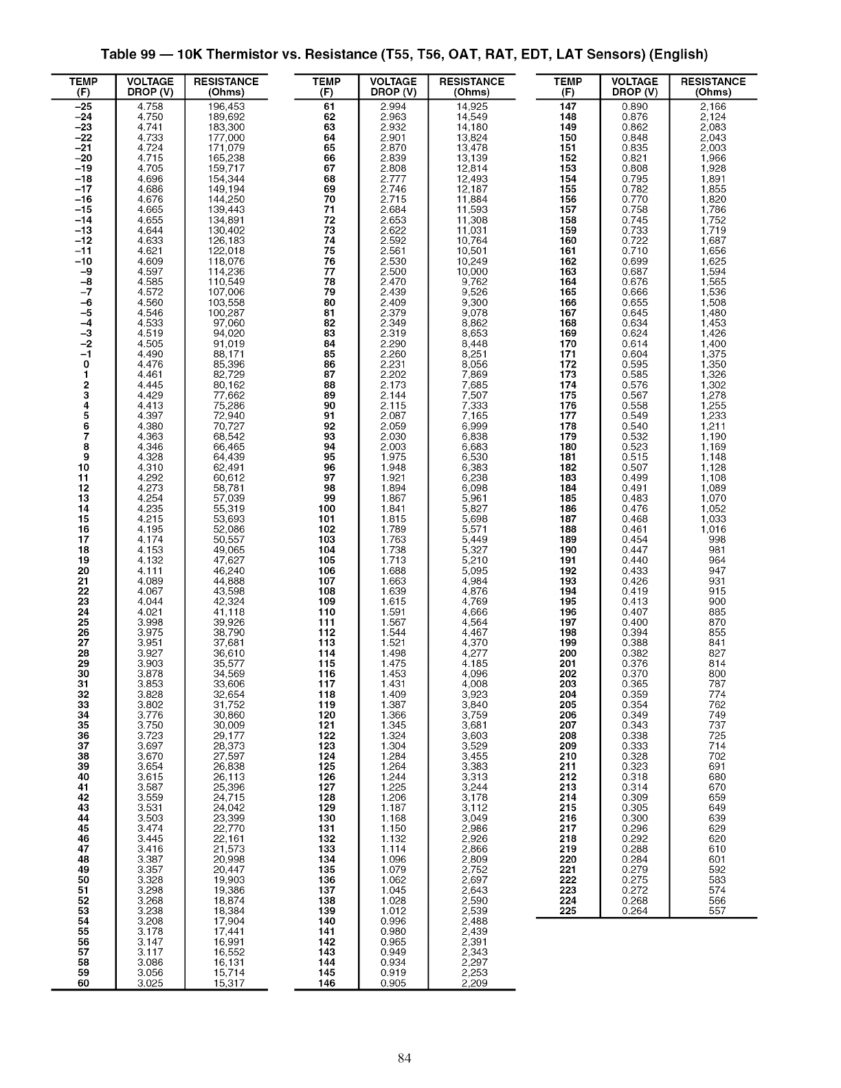
Table 99 -- 10K Thermistor vs. Resistance (T55, T56, OAT, RAT, EDT, LAT Sensors) (English)
TEMP
(F)
-25
-24
-23
-22
-21
-20
-19
-18
-17
-16
-15
-14
-13
-12
-11
-10
-9
-8
-7
-6
-5
-4
-3
-2
-1
0
1
2
3
4
5
6
7
8
9
10
11
12
13
14
15
16
17
18
19
20
21
22
23
24
25
26
27
28
29
30
31
32
33
34
35
36
37
38
39
40
41
42
43
44
45
46
47
48
49
50
51
52
53
54
55
56
57
58
59
60
VOLTAGE
DROP (V)
4.758
4.750
4.741
4.733
4.724
4.715
4.705
4.696
4.686
4.676
4.665
4.655
4.644
4.633
4.621
4.609
4.597
4.585
4.572
4.560
4.546
4.533
4.519
4.505
4.490
4.476
4.461
4.445
4.429
4.413
4.397
4.380
4.363
4.346
4.328
4.310
4.292
4.273
4.254
4.235
4.215
4.195
4.174
4.153
4.132
4.111
4.089
4.067
4.044
4.021
3.998
3.975
3.951
3.927
3.903
3.878
3.853
3.828
3.802
3.776
3.750
3.723
3.697
3.670
3.654
3.615
3.587
3.559
3.531
3.503
3.474
3.445
3.416
3.387
3.357
3.328
3.298
3.268
3.238
3.208
3.178
3.147
3.117
3.086
3.056
3.025
RESISTANCE TEMP
(Ohms) (F)
196,453 61
189,692 62
183,300 63
177,000 64
171,079 65
165,238 66
159,717 67
154,344 68
149,194 69
144,250 70
139,443 71
134,891 72
130,402 73
126,183 74
122,018 75
118,076 76
114,236 77
110,549 78
107,006 79
103,558 80
100,287 81
97,060 82
94,020 83
91,019 84
88,171 85
85,396 86
82,729 87
80,162 88
77,662 89
75,286 90
72,940 91
70,727 92
68,542 93
66,465 94
64,439 95
62,491 96
60,612 97
58,781 98
57,039 99
55,319 100
53,693 101
52,086 102
50,557 103
49,065 104
47,627 105
46,240 106
44,888 107
43,598 108
42,324 109
41,118 110
39,926 111
38,790 112
37,681 113
36,610 114
35,577 115
34,569 116
33,606 117
32,654 118
31,752 119
30,860 120
30,009 121
29,177 122
28,373 123
27,597 124
26,838 125
26,113 126
25,396 127
24,715 128
24,042 129
23,399 130
22,770 131
22,161 132
21,573 133
20,998 134
20,447 135
19,903 136
19,386 137
18,874 138
18,384 139
17,904 140
17,441 141
16,991 142
16,552 143
16,131 144
15,714 145
15,317 146
VOLTAGE
DROP (V)
2.994
2.963
2.932
2.901
2.870
2.839
2.808
2.777
2.746
2.715
2.684
2.653
2.622
2.592
2.561
2.530
2.500
2.470
2.439
2.409
2.379
2.349
2.319
2.290
2.260
2.231
2.202
2.173
2.144
2.115
2.087
2.059
2.030
2.003
1.975
1.948
1.921
1.894
1.867
1.841
1.815
1.789
1.763
1.738
1.713
1.688
1.663
1.639
1.615
1.591
1.567
1.544
1.521
1.498
1.475
1.453
1.431
1.409
1.387
1.366
1.345
1.324
1.304
1.284
1.264
1.244
1.225
1.206
1.187
1.168
1.150
1.132
1.114
1.096
1.079
1.062
1.045
1.028
1.012
0.996
0.980
0.965
0.949
0.934
0.919
0.905
RESISTANCE TEMP
(Ohms) (F)
14,925 147
14,549 148
14,180 149
13,824 150
13,478 151
13,139 152
12,814 153
12,493 154
12,187 155
11,884 156
11,593 157
11,308 158
11,031 159
10,764 160
10,501 161
10,249 162
10,000 163
9,762 164
9,526 165
9,300 166
9,078 167
8,862 168
8,653 169
8,448 170
8,251 171
8,056 172
7,869 173
7,685 174
7,507 175
7,333 176
7,165 177
6,999 178
6,838 179
6,683 180
6,530 181
6,383 182
6,238 183
6,098 184
5,961 185
5,827 186
5,698 187
5,571 188
5,449 189
5,327 190
5,210 191
5,095 192
4,984 193
4,876 194
4,769 195
4,666 196
4,564 197
4,467 198
4,370 199
4,277 200
4.185 201
4,096 202
4,008 203
3,923 204
3,840 205
3,759 206
3,681 207
3,603 208
3,529 209
3,455 210
3,383 211
3,313 212
3,244 213
3,178 214
3,112 215
3,049 216
2,986 217
2,926 218
2,866 219
2,809 220
2,752 221
2,697 222
2,643 223
2,590 224
2,539 225
2,488
2,439
2,391
2,343
2,297
2,253
2,209
VOLTAGE
DROP (V)
0.890
0.876
0.862
0.848
0.835
0.821
0.808
0.795
0.782
0.770
0.758
0.745
0.733
0.722
0.710
0.699
0.687
0.676
0.666
0.655
0.645
0.634
0.624
0.614
0.604
0.595
0.585
0.576
0.567
0.558
0.549
0.540
0.532
0.523
0.515
0.507
0.499
0.491
0.483
0.476
0.468
0.461
0.454
0.447
0.440
0.433
0.426
0.419
0.413
0.407
0.400
0.394
0.388
0.382
0.376
0.370
0.365
0.359
0.354
0.349
0.343
0.338
0.333
0.328
0.323
0.318
0.314
0.309
0.305
0.300
0.296
0.292
0.288
0.284
0.279
0.275
0.272
0.268
0.264
RESISTANCE
(Ohms)
2,166
2,124
2,083
2,043
2,003
1,966
1,928
1,891
1,855
1,820
1,786
1,752
1,719
1,687
1,656
1,625
1,594
1,565
1,536
1,508
1,480
1,453
1,426
1,400
1,375
1,350
1,326
1,302
1,278
1,255
1,233
1,211
1,190
1,169
1,148
1,128
1,108
1,089
1,070
1,052
1,033
1,016
998
981
964
947
931
915
9OO
885
87O
855
841
827
814
8OO
787
774
762
749
737
725
714
7O2
691
68O
67O
659
649
639
629
62O
610
601
592
583
574
566
557
84
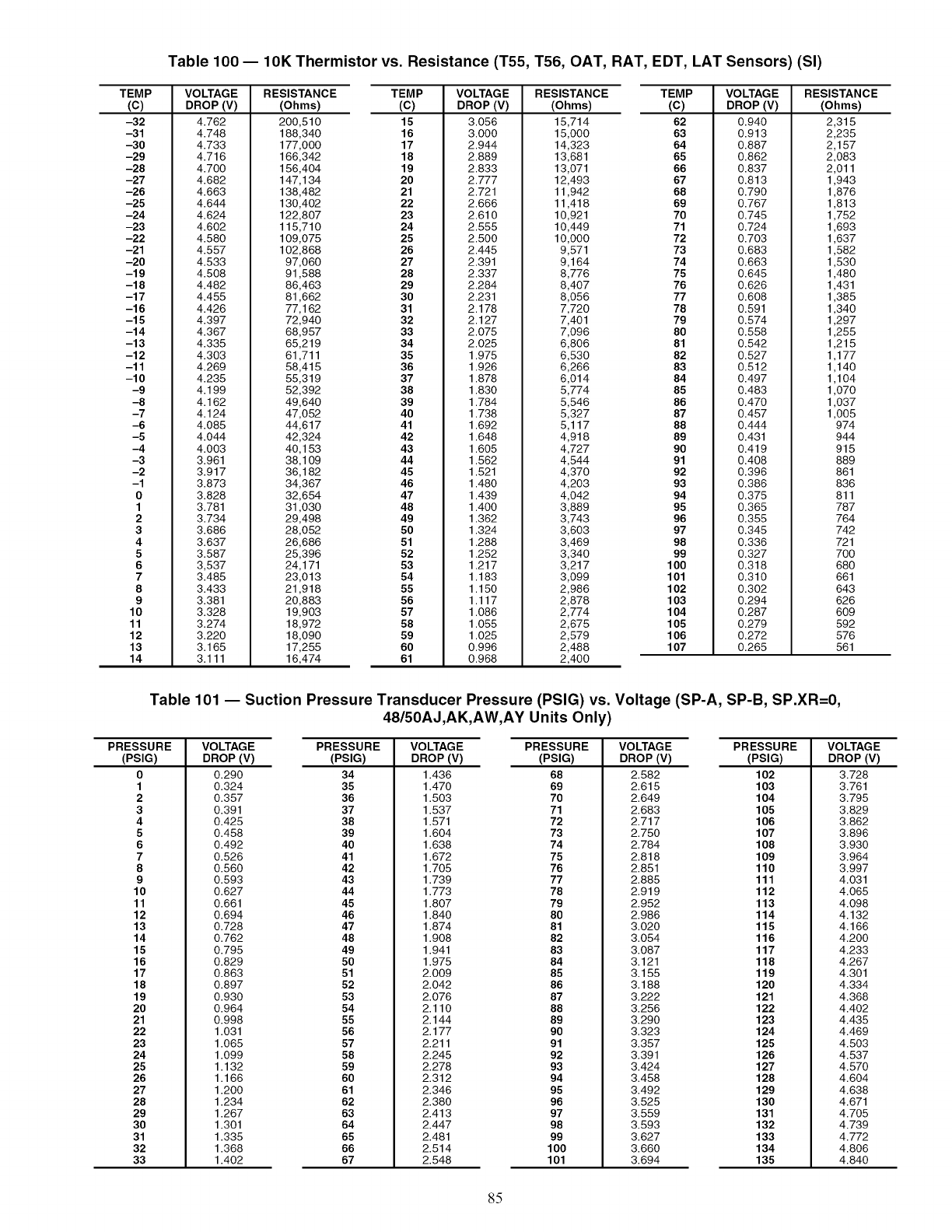
Table 100 -- 10K Thermistor vs. Resistance (T55, T56, OAT, RAT, EDT, LAT Sensors) (SI)
TEMP
(c)
-32
-31
-30
-29
-28
-27
-26
-25
-24
-23
-22
-21
-20
-19
-18
-17
-16
-15
-14
-13
-12
-11
-10
-9
-8
-7
-6
-5
-4
-3
-2
-1
0
1
2
3
4
5
6
7
8
9
10
11
12
13
14
VOLTAGE
DROP (V)
4.762
4.748
4.733
4.716
4.700
4.682
4.663
4.644
4.624
4.602
4.580
4.557
4.533
4.508
4.482
4.455
4.426
4.397
4.367
4.335
4.303
4.269
4.235
4.199
4.162
4.124
4.085
4.044
4.003
3.961
3.917
3.873
3.828
3.781
3.734
3.686
3.637
3.587
3,537
3.485
3.433
3.381
3.328
3.274
3.220
3.165
3.111
RESISTANCE TEMP
(Ohms) (C)
200,510 15
188,340 16
177,000 17
166,342 18
156,404 19
147,134 20
138,482 21
130,402 22
122,807 23
115,710 24
109,075 25
102,868 26
97,060 27
91,588 28
86,463 29
81,662 30
77,162 31
72,940 32
68,957 33
65,219 34
61,711 35
58,415 36
55,319 37
52,392 38
49,640 39
47,052 40
44,617 41
42,324 42
40,153 43
38,109 44
36,182 45
34,367 46
32,654 47
31,030 48
29,498 49
28,052 50
26,686 51
25,396 52
24,171 53
23,013 54
21,918 55
20,883 56
19,903 57
18,972 58
18,090 59
17,255 60
16,474 61
VOLTAGE
DROP (V)
3.056
3.000
2.944
2.889
2.833
2.777
2.721
2.666
2.610
2.555
2.500
2.445
2.391
2.337
2.284
2.231
2.178
2.127
2.075
2.025
1.975
1.926
1.878
1.830
1.784
1.738
1.692
1.648
1.605
1.562
1.521
1.480
1.439
1.400
1.362
1.324
1.288
1.252
1.217
1.183
1.150
1.117
1.086
1.055
1.025
0.996
0.968
RESISTANCE TEMP
(Ohms) (C)
15,714 62
15,000 63
14,323 64
13,681 65
13,071 66
12,493 67
11,942 68
11,418 69
10,921 70
10,449 71
10,000 72
9,571 73
9,164 74
8,776 75
8,407 76
8,056 77
7,720 78
7,401 79
7,096 80
6,806 81
6,530 82
6,266 83
6,014 84
5,774 85
5,546 86
5,327 87
5,117 88
4,918 89
4,727 90
4,544 91
4,370 92
4,203 93
4,042 94
3,889 95
3,743 96
3,603 97
3,469 98
3,340 99
3,217 100
3,099 101
2,986 102
2,878 103
2,774 104
2,675 105
2,579 106
2,488 107
2,400
VOLTAGE
DROP (V)
0.940
0.913
0.887
0.862
0.837
0.813
0.790
0.767
0.745
0.724
0.703
0.683
0.663
0.645
0.626
0.608
0.591
0.574
0.558
0.542
0.527
0.512
0.497
0.483
0.470
0.457
0.444
0.431
0.419
0.408
0.396
0.386
0.375
0.365
0.355
0.345
0.336
0.327
0.318
0.310
0.302
0.294
0.287
0.279
0.272
0.265
RESISTANCE
(Ohms)
2,315
2,235
2,157
2,083
2,011
1,943
1,876
1,813
1,752
1,693
1,637
1,582
1,530
1,480
1,431
1,385
1,340
1,297
1,255
1,215
1,177
1,140
1,104
1,070
1,037
1,005
974
944
915
889
861
836
811
787
764
742
721
7OO
68O
661
643
626
609
592
576
561
Table 101 -- Suction Pressure Transducer Pressure (PSIG) vs. Voltage (SP-A, SP-B, SP.XR=0,
48/50AJ,AK,AW,AY Units Only)
PRESSURE
(PSIG)
0
1
2
3
4
5
6
7
8
9
10
11
12
13
14
15
16
17
18
19
20
21
22
23
24
25
26
27
28
29
30
31
32
33
VOLTAGE
DROP (V)
0.290
0.324
0.357
0.391
0.425
0.458
0.492
0.526
0.560
0.593
0.627
0.661
0.694
0.728
0.762
0.795
0.829
0.863
0.897
0.930
0.964
0.998
1.031
1.065
1.099
1.132
1.166
1.200
1.234
1.267
1.301
1.335
1.368
1.402
PRESSURE VOLTAGE
(PSIG) DROP (V)
34 1.436
35 1.470
36 1.503
37 1.537
38 1.571
39 1.604
40 1.638
41 1.672
42 1.705
43 1.739
44 1.773
45 1.807
46 1.840
47 1.874
48 1.908
49 1.941
50 1.975
51 2.009
52 2.042
53 2.076
54 2.110
55 2.144
56 2.177
57 2.211
58 2.245
59 2.278
60 2.312
61 2.346
62 2.380
63 2.413
64 2.447
65 2.481
66 2.514
67 2.548
PRESSURE
(PSIG)
68
69
70
71
72
73
74
75
76
77
78
79
80
81
82
83
84
85
86
87
88
89
90
91
92
93
94
95
96
97
98
99
100
101
VOLTAGE PRESSURE
DROP (V) (PSIG)
2.582 102
2.615 103
2.649 104
2.683 105
2.717 106
2.750 107
2.784 108
2.818 109
2.851 110
2.885 111
2.919 112
2.952 113
2.986 114
3.020 115
3.054 116
3.087 117
3.121 118
3.155 119
3.188 120
3.222 121
3.256 122
3.290 123
3.323 124
3.357 125
3.391 126
3.424 127
3.458 128
3.492 129
3.525 130
3.559 131
3.593 132
3.627 133
3.660 134
3.694 135
VOLTAGE
DROP (V)
3.728
3.761
3.795
3.829
3.862
3.896
3.930
3.964
3.997
4.031
4.065
4.098
4.132
4.166
4.200
4.233
4.267
4.301
4.334
4.368
4.402
4.435
4.469
4.503
4.537
4.570
4.604
4.638
4.671
4.705
4.739
4.772
4.806
4.840
85
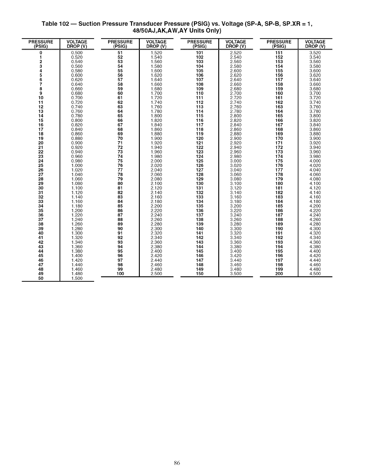
Table 102 -- Suction Pressure Transducer Pressure (PSIG) vs. Voltage (SP-A, SP-B, SP.XR - 1,
48/50AJ,AK,AW,AY Units Only)
PRESSURE
(PSIG)
0
1
2
3
4
5
6
7
8
9
10
11
12
13
14
15
16
17
18
19
20
21
22
23
24
25
26
27
28
29
30
31
32
33
34
35
36
37
38
39
40
41
42
43
44
45
46
47
48
49
50
VOLTAGE PRESSURE
DROP (V) (PSIG)
0.500 51
0.520 52
0.540 53
0.560 54
0.580 55
0.600 56
0.620 57
0.640 58
0.660 59
0.680 60
0.700 61
0.720 62
0.740 63
0.760 64
0.780 65
0.800 66
0.820 67
0.840 68
0.860 69
0.880 70
0.900 71
0.920 72
0.940 73
0.960 74
0.980 75
1.000 76
1.020 77
1.040 78
1.060 79
1.080 80
1.100 81
1.120 82
1.140 83
1.160 84
1.180 85
1.200 86
1.220 87
1.240 88
1.260 89
1.280 90
1.300 91
1.320 92
1.340 93
1.360 94
1.380 95
1.400 96
1.420 97
1.440 98
1.460 99
1.480 100
1.500
VOLTAGE PRESSURE
DROP (V) (PSIG)
1.520 101
1.540 102
1.560 103
1.580 104
1.600 105
1.620 106
1.640 107
1.660 108
1.680 109
1.700 110
1.720 111
1.740 112
1.760 113
1.780 114
1.800 115
1.820 116
1.840 117
1.860 118
1.880 119
1.900 120
1.920 121
1.940 122
1.960 123
1.980 124
2.000 125
2.020 126
2.040 127
2.060 128
2.080 129
2.100 130
2.120 131
2.140 132
2.160 133
2.180 134
2.200 135
2.220 136
2.240 137
2.260 138
2.280 139
2.300 140
2.320 141
2.340 142
2.360 143
2.380 144
2.400 145
2.420 146
2.440 147
2.460 148
2.480 149
2.500 150
VOLTAGE PRESSURE
DROP (V) (PSIG)
2.520 151
2.540 152
2.560 153
2.580 154
2.600 155
2.620 156
2.640 157
2.660 158
2.680 159
2.700 160
2.720 161
2.740 162
2.760 163
2.780 164
2.800 165
2.820 166
2.840 167
2.860 168
2.880 169
2.900 170
2.920 171
2.940 172
2.960 173
2.980 174
3.000 175
3.020 176
3.040 177
3.060 178
3.080 179
3.100 180
3.120 181
3.140 182
3.160 183
3.180 184
3.200 185
3.220 186
3.240 187
3.260 188
3.280 189
3.300 190
3.320 191
3.340 192
3.360 193
3.380 194
3.400 195
3.420 196
3.440 197
3.460 198
3.480 199
3.500 200
VOLTAGE
DROP (V)
3.520
3.540
3.560
3.580
3.600
3.620
3.640
3.660
3.680
3.700
3.720
3.740
3.760
3.780
3.800
3.820
3.840
3.860
3.880
3.900
3.920
3.940
3.960
3.980
4.000
4.020
4.040
4.060
4.080
4.100
4.120
4.140
4.160
4.180
4.200
4.220
4.240
4.260
4.280
4.300
4.320
4.340
4.360
4.380
4.400
4.420
4.440
4.460
4.480
4.500
86
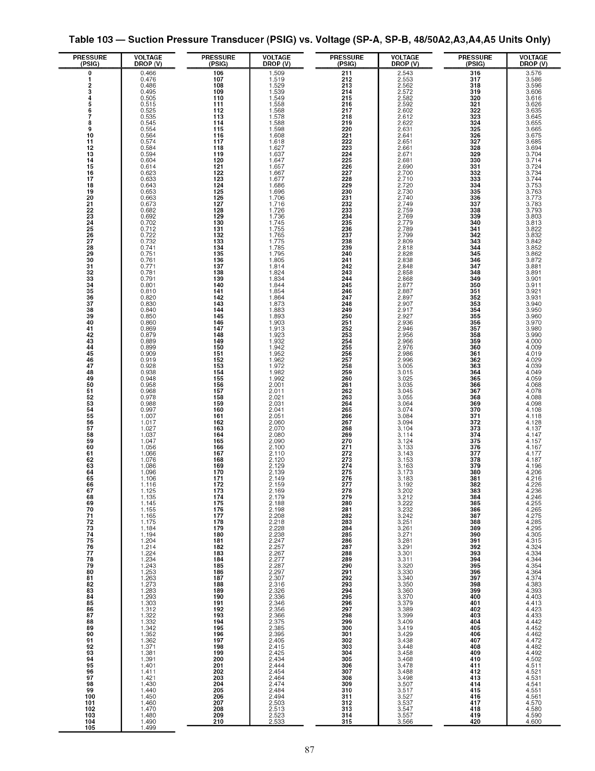
Table 103 -- Suction Pressure Transducer (PSIG) vs. Voltage (SP-A, SP-B, 48/50A2,A3,A4,A5 Units Only)
PRESSURE
PSIG
0
1
2
3
4
5
6
7
8
9
10
11
12
13
14
15
16
17
18
19
20
21
22
23
24
25
26
27
28
29
30
31
32
33
34
35
36
37
38
39
40
41
42
43
44
45
46
47
48
49
50
51
52
53
54
55
56
57
58
59
60
61
62
63
64
65
66
67
68
69
70
71
72
73
74
75
76
77
78
79
80
81
82
83
84
85
86
87
88
89
9O
91
92
93
94
95
96
97
98
99
100
101
102
103
104
105
VOLTAGE PRESSURE
0.466 106
0.476 107
0.486 108
0.495 109
0.505 110
0.515 111
0.525 112
0.535 113
0.545 114
0.554 115
0.564 116
0.574 117
0.584 118
0.594 119
0.604 120
0.614 121
0.623 122
0.633 123
0.643 124
0.653 125
0.663 126
0.673 127
0.682 128
0.692 129
0.702 130
0.712 131
0.722 132
0.732 133
0.741 134
0.751 135
0.761 136
0.771 137
0.781 138
0.791 139
0.801 140
0.810 141
0.820 142
0.830 143
0.840 144
0.850 145
0.860 146
0.869 147
0.879 148
0.889 149
0.899 150
0.909 151
0.919 152
0.928 153
0.938 154
0.948 155
0.958 156
0.968 157
0.978 158
0.988 159
0.997 160
1.007 161
1.017 162
1.027 163
1.037 164
1.047 165
1.056 166
1.066 167
1.076 168
1.086 169
1.096 170
1.106 171
1.116 172
1.125 173
1.135 174
1.145 175
1.155 176
1.165 177
1.175 178
1.184 179
1.194 180
1.204 181
1.214 182
1.224 183
1.234 184
1.243 185
1.253 186
1.263 187
1.273 188
1.283 189
1.293 190
1.303 191
1.312 192
1.322 193
1.332 194
1.342 195
1.352 196
1.362 197
1.371 198
1.381 199
1.391 200
1.401 201
1.411 202
1.421 203
1.430 204
1.440 205
1.450 206
1.460 207
1.470 208
1.480 209
1.490 210
1.499
VOLTAGE PRESSURE
DR_ PSIG
1.509 211
1.519 212
1.529 213
1.539 214
1.549 215
1.558 216
1.568 217
1.578 218
1.588 219
1.598 220
1.608 221
1.618 222
1.627 223
1.637 224
1.647 225
1.657 226
1.667 227
1.677 228
1.686 229
1.696 280
1.706 231
1.716 232
1.726 288
1.736 284
1.745 285
1.755 286
1.765 237
1.775 288
1.785 239
1.795 240
1.805 241
1.814 242
1.824 243
1.834 244
1.844 245
1.854 246
1.864 247
1.873 248
1.883 249
1.893 250
1.903 251
1.913 252
1.923 258
1.932 254
1.942 255
1.952 256
1.962 257
1.972 258
1.982 259
1.992 260
2.001 261
2.011 262
2.021 268
2.031 264
2.041 265
2.051 266
2.060 267
2.070 268
2.080 269
2.090 270
2.100 271
2.110 272
2.120 278
2.129 274
2.139 275
2.149 276
2.159 277
2.169 278
2.179 279
2.188 280
2.198 281
2.208 282
2.218 288
2.228 284
2.238 285
2.247 286
2.257 287
2.267 288
2.277 289
2.287 290
2.297 291
2.307 292
2.316 293
2.326 294
2.336 295
2.346 296
2.356 297
2.366 298
2.375 299
2.385 300
2.395 301
2.405 302
2.415 303
2.425 304
2.434 305
2.444 306
2.454 307
2.464 308
2.474 309
2.484 310
2.494 311
2.503 312
2.513 313
2.523 314
2.533 315
VOLTAGE PRESSURE
PSIG
2.543 316
2.553 317
2.562 318
2.572 319
2.582 320
2.592 321
2.602 322
2.612 323
2.622 324
2.631 325
2.641 326
2.651 327
2.661 328
2.671 329
2.681 330
2.690 381
2.700 382
2.710 333
2.720 384
2.730 385
2.740 386
2.749 387
2.759 388
2.769 339
2.779 340
2.789 341
2.799 342
2.809 343
2.818 344
2.828 345
2.838 346
2.848 347
2.858 348
2.868 349
2.877 350
2.887 351
2.897 352
2.907 353
2.917 354
2.927 355
2.936 356
2.946 357
2.956 358
2.966 359
2.976 360
2.986 361
2.996 362
3.005 368
3.015 364
3.025 365
3.035 366
3.045 367
3.055 368
3.064 369
3.074 370
3.084 371
3.094 372
3.104 373
3.114 374
3.124 375
3.133 376
3.143 377
3.153 378
3.163 379
3.173 380
3.183 381
3.192 382
3.202 388
3.212 384
3.222 385
3.232 386
3.242 387
3.251 388
3.261 389
3.271 390
3.281 391
3.291 392
3.301 393
3.311 394
3.320 395
3.330 396
3.340 397
3.350 398
3.360 399
3.370 400
3.379 401
3.389 402
3.399 408
3.409 404
3.419 405
3.429 406
3.438 407
3.448 408
3.458 409
3.468 410
3.478 411
3.488 412
3.498 413
3.507 414
3.517 415
3.527 416
3.537 417
3.547 418
3.557 419
3.566 420
VOLTAGE
3.576
3.586
3.596
3.606
3.616
3.626
3.635
3.645
3.655
3.665
3.675
3.685
3.694
3.704
3.714
3.724
3.734
3.744
3.753
3.763
3.773
3.783
3,793
3.803
3.813
3.822
3.832
3.842
3.852
3.862
3.872
3.881
3.891
3.901
3.911
3.921
3.931
3.940
3.950
3.960
3.970
3.980
3.990
4.000
4.009
4.019
4.029
4.039
4.049
4.059
4.068
4.078
4.088
4.098
4.108
4.118
4.128
4.137
4.147
4.157
4.167
4.177
4.187
4.196
4.206
4.216
4.226
4.236
4.246
4.255
4.265
4.275
4.285
4.295
4.305
4.315
4.324
4.334
4.344
4.354
4.364
4.374
4.383
4.393
4.403
4.413
4.423
4.433
4.442
4.452
4.462
4.472
4.482
4.492
4.502
4.511
4.521
4.531
4.541
4.551
4.561
4.570
4.580
4.590
4.600
87
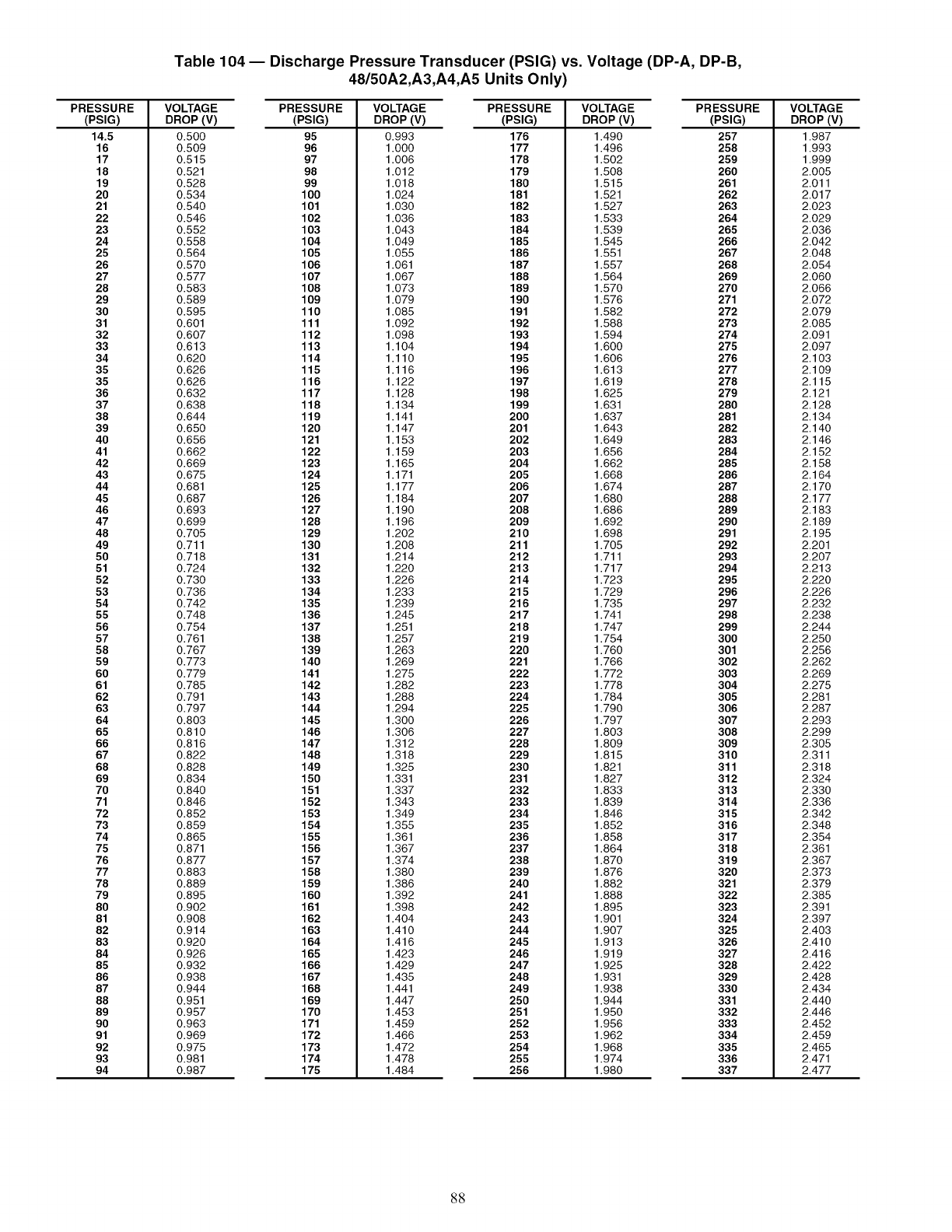
Table 104 -- Discharge Pressure Transducer (PSIG) vs. Voltage (DP-A, DP-B,
48/50A2,A3,A4,A5 Units Only)
PRESSURE
(PSIG)
14.5
16
17
18
19
20
21
22
23
24
25
26
27
28
29
30
31
32
33
34
35
35
36
37
38
39
40
41
42
43
44
45
46
47
48
49
50
51
52
53
54
55
56
57
58
59
60
61
62
63
64
65
66
67
68
69
70
71
72
73
74
75
76
77
78
79
80
81
82
83
84
85
86
87
88
89
90
91
92
93
94
VOLTAGE PRESSURE
DROP (V) (PSIG)
0.500 95
0.509 96
0.515 97
0.521 98
0.528 99
0.534 100
0.540 101
0.546 102
0.552 103
0.558 104
0.564 105
0.570 106
0.577 107
0.583 108
0.589 109
0.595 110
0.601 111
0.607 112
0.613 113
0.620 114
0.626 115
0.626 116
0.632 117
0.638 118
0.644 119
0.650 120
0.656 121
0.662 122
0.669 123
0.675 124
0.681 125
0.687 126
0.693 127
0.699 128
0.705 129
0.711 130
0.718 131
0.724 132
0.730 133
0.736 134
0.742 135
0.748 136
0.754 137
0.761 138
0.767 139
0.773 140
0.779 141
0.785 142
0.791 143
0.797 144
0.803 145
0.810 146
0.816 147
0.822 148
0.828 149
0.834 150
0.840 151
0.846 152
0.852 153
0.859 154
0.865 155
0.871 156
0.877 157
0.883 158
0.889 159
0.895 160
0.902 161
0.908 162
0.914 163
0.920 164
0.926 165
0.932 166
0.938 167
0.944 168
0.951 169
0.957 170
0.963 171
0.969 172
0.975 173
0.981 174
0.987 175
VOLTAGE PRESSURE
DROP(V) (PSIG)
0.993 176
1.000 177
1.006 178
1.012 179
1.018 180
1.024 181
1.030 182
1.036 183
1.043 184
1.049 185
1.055 186
1.061 187
1.067 188
1.073 189
1.079 190
1.085 191
1.092 192
1.098 193
1.104 194
1.110 195
1.116 196
1.122 197
1.128 198
1.134 199
1.141 200
1.147 201
1.153 202
1.159 203
1.165 204
1.171 205
1.177 206
1.184 207
1.190 208
1.196 209
1.202 210
1.208 211
1.214 212
1.220 213
1.226 214
1.233 215
1.239 216
1.245 217
1.251 218
1.257 219
1.263 220
1.269 221
1.275 222
1.282 223
1.288 224
1.294 225
1.300 226
1.306 227
1.312 228
1.318 229
1.325 230
1.331 231
1.337 232
1.343 233
1.349 234
1.355 235
1.361 236
1.367 237
1.374 238
1.380 239
1.386 240
1.392 241
1.398 242
1.404 243
1.410 244
1.416 245
1.423 246
1.429 247
1.435 248
1.441 249
1.447 250
1.453 251
1.459 252
1.466 253
1.472 254
1.478 255
1.484 256
VOLTAGE PRESSURE
DROP (V) (PSIG)
1.490 257
1.496 258
1.502 259
1.508 260
1.515 261
1.521 262
1.527 263
1.533 264
1.539 265
1.545 266
1.551 267
1.557 268
1.564 269
1.570 270
1.576 271
1.582 272
1.588 273
1.594 274
1.600 275
1.606 276
1.613 277
1.619 278
1.625 279
1.631 280
1.637 281
1.643 282
1.649 283
1.656 284
1.662 285
1.668 286
1.674 287
1.680 288
1.686 289
1.692 290
1.698 291
1.705 292
1.711 293
1.717 294
1.723 295
1.729 296
1.735 297
1.741 298
1.747 299
1.754 300
1.760 301
1.766 302
1.772 303
1.778 304
1.784 305
1.790 306
1.797 307
1.803 308
1.809 309
1.815 310
1.821 311
1.827 312
1.833 313
1.839 314
1.846 315
1.852 316
1.858 317
1.864 318
1.870 319
1.876 320
1.882 321
1.888 322
1.895 323
1.901 324
1.907 325
1.913 326
1.919 327
1.925 328
1.931 329
1.938 330
1.944 331
1.950 332
1.956 333
1.962 334
1.968 335
1.974 336
1.980 337
VOLTAGE
DROP (V)
1.987
1.993
1.999
2.005
2.011
2.017
2.023
2.029
2.036
2.042
2.048
2.054
2.060
2.066
2.072
2.079
2.085
2.091
2.097
2.103
2.109
2.115
2.121
2.128
2.134
2.140
2.146
2.152
2.158
2.164
2.170
2.177
2.183
2.189
2.195
2.201
2.207
2.213
2.220
2.226
2.232
2.238
2.244
2.250
2.256
2.262
2.269
2.275
2.281
2.287
2.293
2.299
2.305
2.311
2.318
2.324
2.330
2.336
2.342
2.348
2.354
2.361
2.367
2.373
2.379
2.385
2.391
2.397
2.403
2.410
2.416
2.422
2.428
2.434
2.440
2.446
2.452
2.459
2.465
2.471
2.477
88
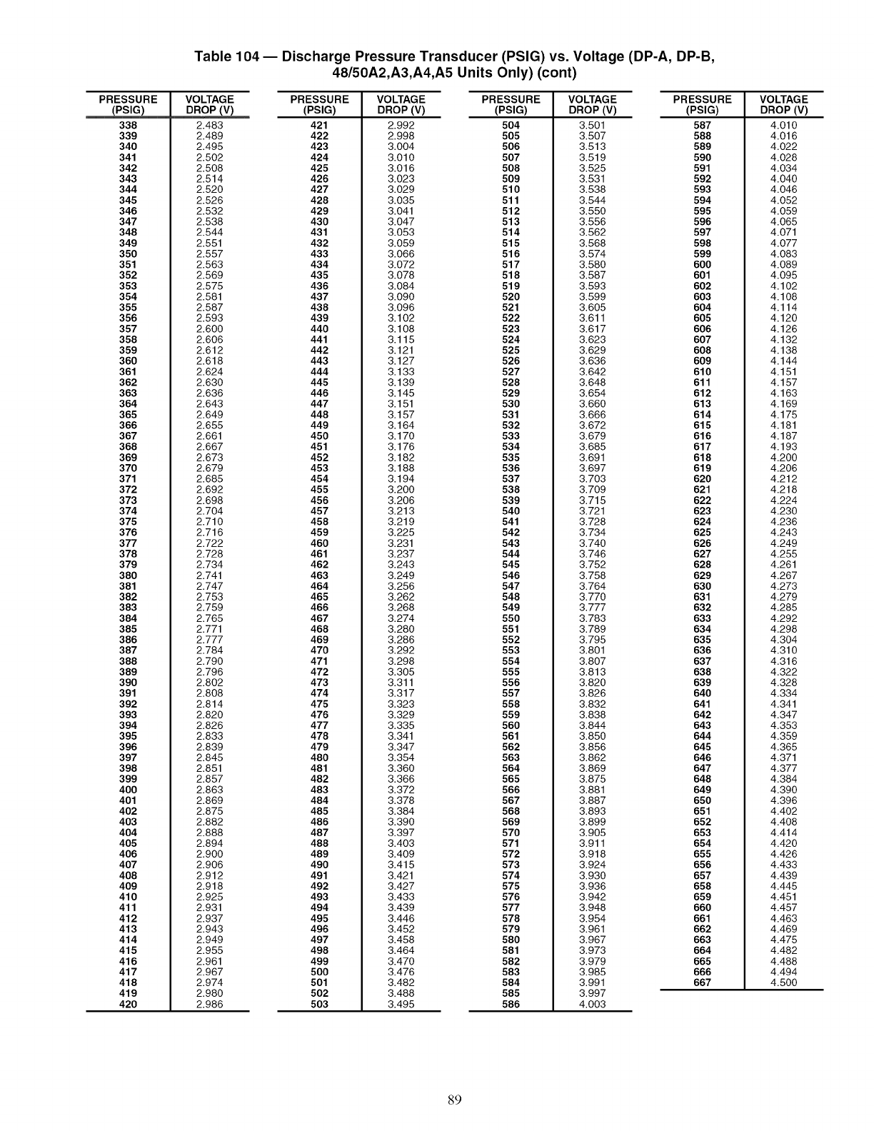
Table 104 -- Discharge Pressure Transducer (PSIG) vs. Voltage (DP-A, DP-B,
48/50A2,A3,A4,A5 Units Only) (cont)
PRESSURE
(PSIG)
338
339
340
341
342
343
344
345
346
347
348
349
350
351
352
353
354
355
356
357
358
359
360
361
362
363
364
365
366
367
368
369
370
371
372
373
374
375
376
377
378
379
380
381
382
383
384
385
386
387
388
389
390
391
392
393
394
395
396
397
398
399
400
401
402
403
404
405
406
407
408
409
410
411
412
413
414
415
416
417
418
419
420
VOLTAGE PRESSURE
DROP (V) (PSIG)
2.483 421
2.489 422
2.495 423
2.502 424
2.508 425
2.514 426
2.520 427
2.526 428
2.532 429
2.538 430
2.544 431
2.551 432
2.557 433
2.563 434
2.569 435
2.575 436
2.581 437
2.587 438
2.593 439
2.600 440
2.606 441
2.612 442
2.618 443
2.624 444
2.630 445
2.636 446
2.643 447
2.649 448
2.655 449
2.661 450
2.667 451
2.673 452
2.679 453
2.685 454
2.692 455
2.698 456
2.704 457
2.710 458
2.716 459
2.722 460
2.728 461
2.734 462
2.741 463
2.747 464
2.753 465
2.759 466
2.765 467
2.771 468
2.777 469
2.784 470
2.790 471
2.796 472
2.802 473
2.808 474
2.814 475
2.820 476
2.826 477
2.833 478
2.839 479
2.845 480
2.851 481
2.857 482
2.863 483
2.869 484
2.875 485
2.882 486
2.888 487
2.894 488
2.900 489
2.906 490
2.912 491
2.918 492
2.925 493
2.931 494
2.937 495
2.943 496
2.949 497
2.955 498
2.961 499
2.967 500
2.974 501
2.980 502
2.986 503
VOLTAGE PRESSURE
DROP(V) (PSlG)
2.992 504
2.998 505
3.004 506
3.010 507
3.016 508
3.023 509
3.029 510
3.035 511
3.041 512
3.047 513
3.053 514
3.059 515
3.066 516
3.072 517
3.078 518
3.084 519
3.090 520
3.096 521
3.102 522
3.108 523
3.115 524
3.121 525
3.127 526
3.133 527
3.139 528
3.145 529
3.151 530
3.157 531
3.164 532
3.170 533
3.176 534
3.182 535
3.188 536
3.194 537
3.200 538
3.206 539
3.213 540
3.219 541
3.225 542
3.231 543
3.237 544
3.243 545
3.249 546
3.256 547
3.262 548
3.268 549
3.274 550
3.280 551
3.286 552
3.292 553
3.298 554
3.305 555
3.311 556
3.317 557
3.323 558
3.329 559
3.335 560
3.341 561
3.347 562
3.354 563
3.360 564
3.366 565
3.372 566
3.378 567
3.384 568
3.390 569
3.397 570
3.403 571
3.409 572
3.415 573
3.421 574
3.427 575
3.433 576
3.439 577
3.446 578
3.452 579
3.458 580
3.464 581
3.470 582
3.476 583
3.482 584
3.488 585
3.495 586
VOLTAGE PRESSURE
DROP (V) (PSIG)
3.501 587
3.507 588
3.513 589
3.519 590
3.525 591
3.531 592
3.538 593
3.544 594
3.550 595
3.556 596
3.562 597
3.568 598
3.574 599
3.580 600
3.587 601
3.593 602
3.599 603
3.605 604
3.611 605
3.617 606
3.623 607
3.629 608
3.636 609
3.642 610
3.648 611
3.654 612
3.660 613
3.666 614
3.672 615
3.679 616
3.685 617
3.691 618
3.697 619
3.703 620
3.709 621
3.715 622
3.721 623
3.728 624
3.734 625
3.740 626
3.746 627
3.752 628
3.758 629
3.764 630
3.770 631
3.777 632
3.783 633
3.789 634
3.795 635
3.801 636
3.807 637
3.813 638
3.820 639
3.826 640
3.832 641
3.838 642
3.844 643
3.850 644
3.856 645
3.862 646
3.869 647
3.875 648
3.881 649
3.887 650
3.893 651
3.899 652
3.905 653
3.911 654
3.918 655
3.924 656
3.930 657
3.936 658
3.942 659
3.948 660
3.954 661
3.961 662
3.967 663
3.973 664
3.979 665
3.985 666
3.991 667
3.997
4.003
VOLTAGE
DROP (V)
4.010
4.016
4.022
4.028
4.034
4.040
4.046
4.052
4.059
4.065
4.071
4.077
4.083
4.089
4.095
4.102
4.108
4.114
4.120
4.126
4.132
4.138
4.144
4.151
4.157
4.163
4.169
4.175
4.181
4.187
4.193
4.200
4.206
4.212
4.218
4.224
4.230
4.236
4.243
4.249
4.255
4.261
4.267
4.273
4.279
4.285
4.292
4.298
4.304
4.310
4.316
4.322
4.328
4.334
4.341
4.347
4.353
4.359
4.365
4.371
4.377
4.384
4.390
4.396
4.402
4.408
4.414
4.420
4.426
4.433
4.439
4.445
4.451
4.457
4.463
4.469
4.475
4.482
4.488
4.494
4.500
89
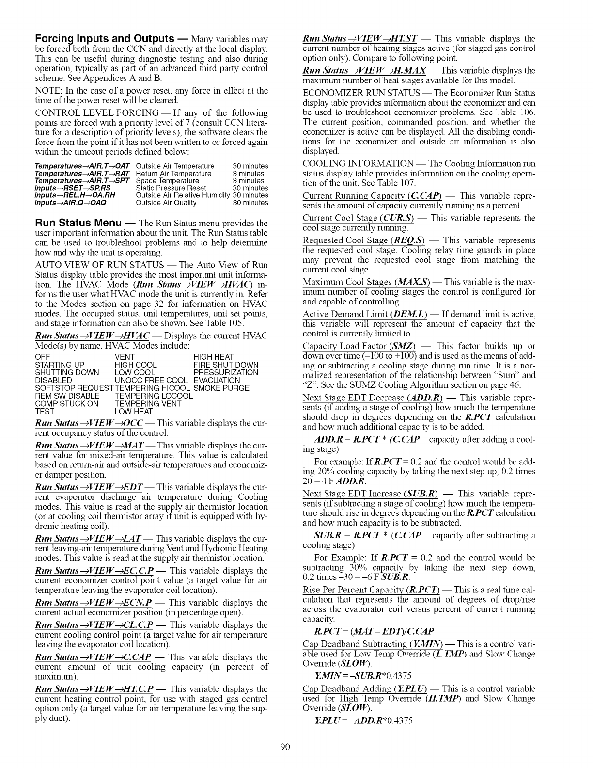
Forcing Inputs and Outputs -- Many variables may
be forced both frolI1 the CCN and directly at the local display.
This can be useful during diagnostic testing and also during
operation, typically as part of an advanced third party control
scheme. See Appendices A and B.
NOTE: In the case of a power reset, any force in effect at the
time of the power reset will be cleared.
CONTROL LEVEL FORCING -- If any of the following
points are forced with a priority level of 7 (consult CCN litera-
ture for a description of priority levels), the software clears the
force frolI1 the point if it has not been written to or forced again
within the timeont periods defined below:
Temperatures-_AIR.T-+OAT Outside Air Temperature 30 minutes
Temperatures-_AIR.T-+RAT Return Air Temperature 3 minutes
Temperatures-_AIR.T-+SPT Space Temperature 3 minutes
Inputs-_RSET-+SP.RS Static Pressure Reset 30 minutes
Inputs-_REL.H-_OA.RH Outside Air Relative Humidity 30 minutes
Inputs-_AIR.Q-+OAQ Outside Air Quality 30 minutes
Run Status Menu -- TheRun Status menu provides the
user important information about the unit. The Run Status table
can be used to troubleshoot problems and to help determine
how and why the unit is operating.
AUTO VIEW OF RUN STATUS -- The Auto View of Run
Status display table provides the most important unit informa-
tion. The HVAC Mode (Run Status--->VIEW--+HVA(_) in-
forms the user what HVAC mode the unit is currently in. Refer
to the Modes section on page 32 for information on HVAC
modes. The occupied status, unit temperatures, unit set points,
and stage information can also be shown. See Table 105.
Run Status-+VIEW-+HVA C -- Displays the current HVAC
Mode(s) by name. HVAC Modes include:
OFF VENT HIGHHEAT
STARTINGUP HIGH COOL FIRESHUTDOWN
SHUTTINGDOWN LOW COOL PRESSURIZATION
DISABLED UNOCC FREECOOL EVACUATION
SOFTSTOPREQUESTTEMPERINGHICOOL SMOKE PURGE
REM SW DISABLE TEMPERING LOCOOL
COMPSTUCK ON TEMPERINGVENT
TEST LOW HEAT
Run Status--_VIEW_OCC- This variable displays the cur-
rent occupancy status of the control.
Run Status--_VIEW--_MAT--This variable displays the cur-
rent value for lnixed-air temperature. This value is calculated
based on return-air and outside-mar temperatures and economiz-
er damper position.
Run Status--->VIEW--->EDT-- This variable displays the cur-
rent evaporator discharge air temperature during Cooling
modes. This value is read at the supply air thermistor location
(or at cooling coil thermistor array if unit is equipped with hy-
dronic heating coil).
Run Status--->VIEW--->LAT-- This variable displays the cur-
rent leaving-air temperature during Vent and Hydronic Heating
modes. This value is read at the supply air themlistor location.
Run Status--_VIEW--_E(L (LP -- This variable displays the
current econolnizer control point value (a target value for air
temperature leaving the evaporator coil location).
Run Status-->VIEW-->ECN.P- This variable displays the
current actual economizer position (in percentage open).
Run Status-->VIEW_,CL(AP -- This variable displays the
current cooling control point (a target value for aiartemperature
leaving the evaporator coil location).
Run Status--_VIEW_: CAP -- This variable displays the
current amount of unit cooling capacity (in percent of
lllaxilllUlI1).
Run Status--+VIEW--cHr. C.P -- This variable displays the
current heating control point, for use with staged gas control
option only (a target value for air temperature leaving the sup-
ply duct).
Run Status-+VIEW--cHEST -- This variable displays the
current number of heating stages active (for staged gas control
option only). Compare to following point.
Run Status--+VIE W--+H.MAX-- This variable displays the
maxilnum number of heat stages available for this model.
ECONOMIZER RUN STATUS -- The Economizer Run Status
display table provides information about the economizer and can
be used to troubleshoot economizer problems. See Table 106.
The current position, commanded position, and whether the
economizer is active can be displayed. All the disabling condi-
tions for the economizer and outside air information is also
displayed.
COOL1NG INFORMATION -- The Cooling Information run
status display table provides information on the cooling opera-
tion of the unit. See Table 107.
Current Running Capacity (C(_5tP) -- This variable repre-
sents the amount of capacity currently running as a percent.
Current Cool Stage (CUR.S) -- This variable represents the
cool stage currently running.
Requested Cool Stage (REQ.S) -- This variable represents
the requested cool stage. Cooling relay time guards in place
may prevent the requested cool stage from matching the
current cool stage.
Maximum Cool Stages (MAX.S) -- This variable is the max-
imum number of cooling stages the control is configured for
and capable of controlling.
Active Demand Limit (DEM.L) -- If demand limit is active,
this variable will represent the amount of capacity that the
control is currently limited to.
Capacity Load Factor (SMZ) -- This factor builds up or
down over time (-100 to +100) and is used as the means of add-
ing or subtracting a cooling stage during run time. It is a nor-
malized representation of the relationship between "Sum" and
"Z". See the SUMZ Cooling Algorithm section on page 46.
Next Stage EDT Decrease (ADD.R) -- This variable repre-
sents (if adding a stage of cooling) how much the temperature
should drop in degrees depending on the R.PCT calculation
and how much additional capacity is to be added.
ADD.R =R.PCT *(C (_MP - capacity after adding a cool-
ing stage)
For example: IfR.PCT = 0.2 and the control would be add-
ing 20% cooling capacity by taking the next step up, 0.2 times
20 = 4 F ADD.R.
Next Stage EDT Increase (SUB.R) -- This variable repre-
sents (if subtracting a stage of cooling) how much the tempera-
lure should rise in degrees depending on the R.PCT calculation
and how much capacity is to be subtracted.
SUB.R =R,PCT *(C (25tP - capacity after subtracting a
cooling stage)
For Example: If R.PCT = 0.2 and the control would be
subtracting 30% capacity by taking the next step down,
0.2 times -30 = -6 F SUB.R.
Rise Per Percent Capacity (R.PCT) -- This is a real time cal-
culation that represents the amount of degrees of drop/rise
across the evaporator coil versus percent of current running
capacity.
R.PCT = (MAT- EDT)/C. CAP
Cap Deadband Subtracting (YMIN) -- This is a control vari-
able used for Low Temp Override (L. TMP) and Slow Change
Ovemde (SLOW).
YMIN = -SUB.R*0.4375
Cap Deadband Adding (YPLU) --This is a control variable
used for High Temp Ovemde (H.TMP) and Slow Change
Ovemde (SLOW).
Y.PLU = -ADD.R*0.4375
9O
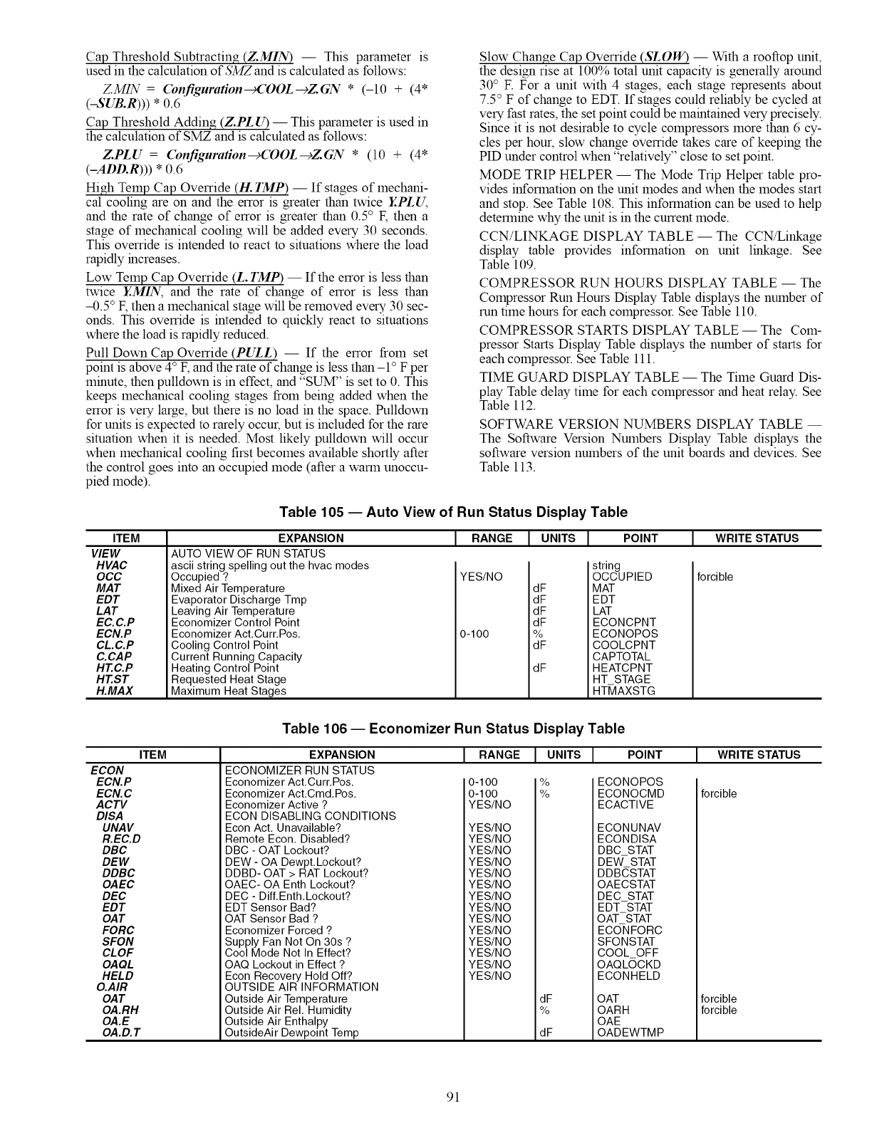
Cap Threshold Subtracting (Z.MIN) -- This parameter is
used in the calculation of 334Z and is calculated as follows:
ZMIN = (bnfiguration_COOL--cZGN * (-10 + (4*
(-SUB.R))) *0.6
Cap Threshold Adding (Z.PLU) -- This parameter is used in
the calculation of SMZ and is calculated as follows:
Z.PLU =(bnfiguration--c(OOL--cZGN * (10 + (4*
(-ADD.R))) * 0.6
High Temp Cap Override (H. IMP) -- if stages of mechani-
cal cooling are on and the error is greater than twice Y.PLU,
and the rate of change of error is greater than 0.5° E then a
stage of mechanical cooling will be added every 30 seconds.
This override is intended to react to situations where the load
rapidly increases.
Low Temp Cap Override (L. IMP) -- If the error is less than
twice Y.MIN, and the rate of change of error is less than
-0.5 ° E then a mechanical stage will be removed every 30 sec-
onds. This override is intended to quickly react to situations
where the load is rapidly reduced.
Pull Down Cap Override (PULL) -- If the error from set
point is above 4° E and the rate of change is less than -1 ° F per
minute, then pulldown is in effect, and "SUM" is set to 0. This
keeps mechanical cooling stages from being added when the
error is very large, but there is no load in the space. Pulldown
for units is expected to rarely occur, but is included for the rare
situation when it is needed. Most likely pulldown will occur
when mechanical cooling first becomes available shortly after
the control goes into an occupied mode (after a warm unoccu-
pied mode).
Slow Change Cap Override (SLOW) -- With a rooftop unit,
the design rise at 100% total unit capacity is generally around
30 ° F. For a unit with 4 stages, each stage represents about
7.5 ° F of change to EDT. If stages could reliably be cycled at
very fast rates, the set point could be maintained very precisely.
Since it is not desirable to cycle compressors more than 6 cy-
cles per hour, slow change override takes care of keeping the
PID under control when "relatively" close to set point.
MODE TRIP HELPER -- The Mode Trip Helper table pro-
vides information on the unit modes and when the modes start
and stop. See Table 108. This information can be used to help
determine why the unit is in the current mode.
CCN/LINKAGE DISPLAY TABLE -- The CCN/Linkage
display table provides information on unit linkage. See
Table 109.
COMPRESSOR RUN HOURS DISPLAY TABLE -- The
Compressor Run Hours Display Table displays the number of
mn time hours for each compressor. See Table 110.
COMPRESSOR STARTS DISPLAY TABLE -- The Com-
pressor Starts Display Table displays the number of starts for
each compressor. See Table 111.
TIME GUARD DISPLAY TABLE -- The Time Guard Dis-
play Table delay time for each compressor and heat relay. See
Table 112.
SOFTWARE VERSION NUMBERS DISPLAY TABLE --
The Software Version Numbers Display Table displays the
software version numbers of the unit boards and devices. See
Table 113.
ITEM
VIEW
HVAC
OCC
MAT
EDT
LAT
EC.C.P
ECN.P
CL.C.P
C.CAP
HT.C.P
HT.ST
H.MAX
Table 105 -- Auto View of Run Status Display Table
EXPANSION
AUTO VIEW OF RUN STATUS
ascii string spelling out the hvac modes
Occupied ?
Mixed Air Temperature
Evaporator Discharge Tmp
Leaving Air Temperature
Economizer Control Point
Economizer Act,Curr, Pos,
Cooling Control Point
Current Running Capacity
Heating Control Point
Requested Heat Stage
Maximum Heat Stages
RANGE I UNITS I POINT
YES/NO
0-100
dF
dF
dF
Jr
dF
dF
string
OCCUPIED
MAT
EDT
LAT
ECONCPNT
ECONOPOS
COOLCPNT
CAPTOTAL
HEATCPNT
HT STAGE
HT_IAXSTG
WRITE STATUS
forcible
ECON
ECN.P
ECN. C
ACTV
DISA
UNAV
R.EC.D
DBC
DEW
DDBC
OAEC
DEC
EDT
OAT
FORC
SFON
CLOF
OAQL
HELD
O.AIR
OAT
OA.RH
OA.E
OA.D. T
ITEM
Table 106 -- Economizer Run Status Display Table
EXPANSION
ECONOMIZER RUN STATUS
Economizer Act,Curr, Pos,
Economizer Act,Cmd,Pos,
Economizer Active ?
ECON DISABLING CONDITIONS
Econ Act, Unavailable?
Remote Econ, Disabled?
DBC - OAT Lockout?
DEW - OA Dewpt, Lockout?
DDBD- OAT > RAT Lockout?
RANGE I UNITSI POINT
0-1 O0
0-1 O0
YES/NO
YES/NO
YES/NO
YES/NO
YES/NO
YES/NO
ECONOPOS
ECONOCMD
ECACTIVE
ECONUNAV
ECONDISA
DBC STAT
DEW- STAT
DDBCSTAT
WRITE STATUS
forcible
OAEC- OA Enth Lockout?
DEC - Diff, Enth,Lockout?
EDT Sensor Bad?
OAT Sensor Bad ?
Economizer Forced ?
Supply Fan Not On 30s ?
Cool Mode Not In Effect?
OAQ Lockout in Effect ?
Econ Recovery Hold Off?
OUTSIDE AIR INFORMATION
Outside Air Temperature
Outside Air Rel, Humidity
Outside Air Enthalpy
OutsideAir Dewpoint Temp
YES/NO
YES/NO
YES/NO
YES/NO
YES/NO
YES/NO
YES/NO
YES/NO
YES/NO
OAECSTAT
DEC_STAT
EDT STAT
OAT STAT
ECONFORC
SFONSTAT
COOL OFF
OAQLOCKD
ECONHELD
OAT
OARH
OAE
OADEWTMP
forcible
forcible
91
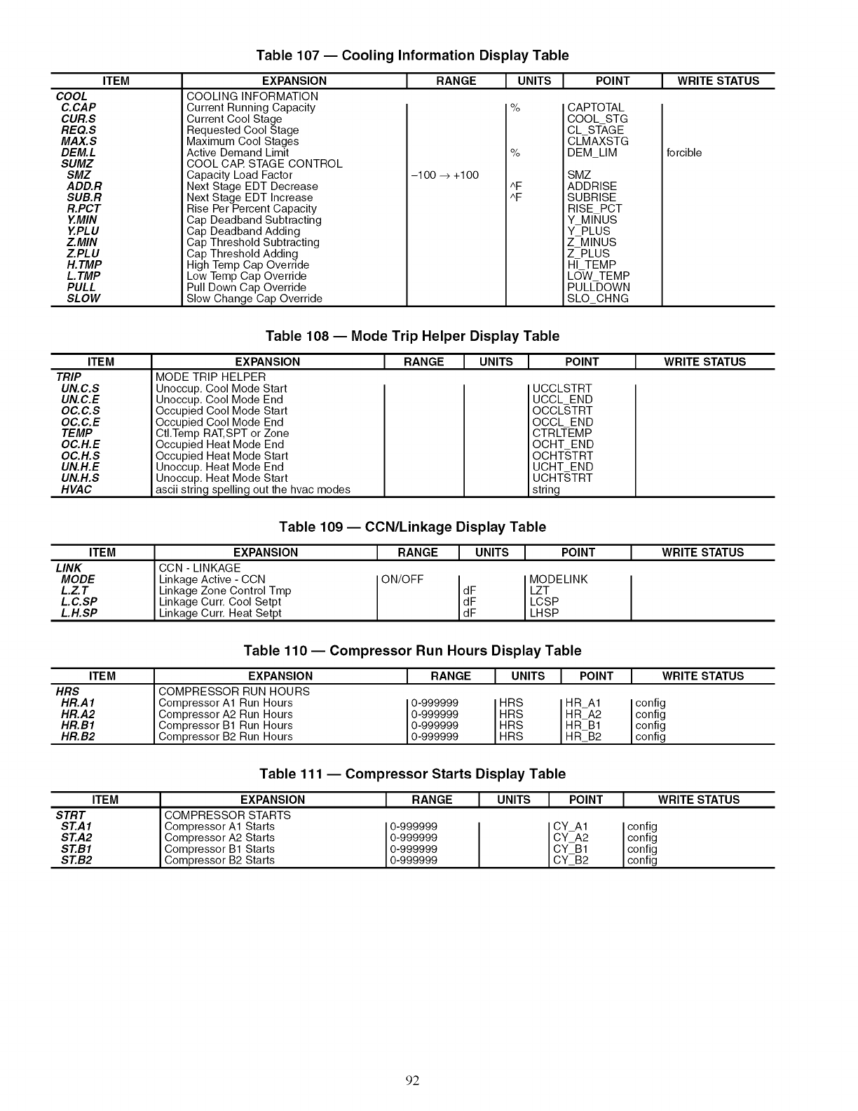
ITEM
COOL
C.CAP
CUR.S
REQ.S
MAX.S
DEM.L
SUMZ
SMZ
ADD.R
SUB.R
R.PCT
Y.MIN
YPLU
ZMIN
ZPLU
H.TMP
L TMP
PULL
SLOW
Table 107- Cooling Information Display Table
EXPANSION
COOLING INFORMATION
Current Running Capacity
Current Cool Stage
Requested Cool Stage
Maximum Cool Stages
Active Demand Limit
COOL CAR STAGE CONTROL
Capacity Load Factor
Next Stage EDT Decrease
Next Stage EDT Increase
Rise Per Percent Capacity
Cap Deadband Subtracting
Cap Deadband Adding
Cap Threshold Subtracting
Cap Threshold Adding
High Temp Cap Override
Low Temp Cap Override
Pull Down Cap Override
Slow Change Cap Override
RANGE
-1 O0 -_ +1 O0
I UNITS
%
%
^F
^F
I POINT
CAPTOTAL
COOL STG
CL ST-AGE
CL_IAXSTG
DEM_LIM
SMZ
ADDRISE
SUBRISE
RISE PCT
Y_MlhlUS
Y_PLUS
Z_MINUS
ZPLUS
HI TEMP
LOW TEMP
PULLDOWN
SLO CHNG
WRITE STATUS
forcible
ITEM
TRIP
UN.C.S
UN.C.E
OC.C.S
OC.C.E
TEMP
OC.H.E
OC.H.S
UN.H.E
UN.H.S
HVAC
Table 108 -- Mode Trip Helper Display Table
EXPANSION
MODE TRIP HELPER
Unoccup. Cool Mode Start
Unoccup. Cool Mode End
Occupied Cool Mode Start
Occupied Cool Mode End
CtI.Temp RAT,SPT or Zone
Occupied Heat Mode End
Occupied Heat Mode Start
Unoccup. Heat Mode End
Unoccup. Heat Mode Start
ascii string spelling out the hvac modes
J RANGE [UNITS j. POINT
UCCLSTRT
UCCL END
OCCLSTRT
OCCL END
CTRLTEMP
OCHT END
OCHT,STRT
UCHT END
UCHT,STRT
string
WRITE STATUS
Table 109 -- CCN/Linkage Display Table
ITEM
LINK
MODE
L.Z.T
LC.SP
LH.SP
EXPANSION I RANGE
CCN - LINKAGE
Linkage Active - CCN ON/OFF
Linkage Zone Control Tmp
Linkage Curr. Cool Setpt
Linkage Curr. Heat Setpt
I UNITS I WRITE STATUSIPOINT
MODELINK
dF LZT
dF LCSP
dF LHSP
Table 110- Compressor Run Hours Display Table
ITEM EXPANSION I RANGEI UNITSI POINTI WRITESTATUS
HRS COMPRESSOR RUN HOURS
HR.AI Compressor A1 Run Hours 0-999999 HRS HR_A1 config
HR.A2 Compressor A2 Run Hours 0-999999 HRS HR_A2 config
HR.BI Compressor B1 Run Hours 0-999999 HRS HR_B1 config
HR.B2 Compressor B2 Run Hours 0-999999 HRS HR_B2 config
Table 111 -- Compressor Starts Display Table
ITEM EXPANSION IRANGE I UNITS I POINT IWRITE STATUS
STRT COMPRESSOR STARTS
ST.AI Compressor A1 Starts 0-999999 CYA1 config
ST.A2 Compressor A2 Starts 0-999999 CYA2 config
ST.BI Compressor B1 Starts 0-999999 CY_B1 config
ST.B2 Compressor B2 Starts 0-999999 CY_B2 config
92
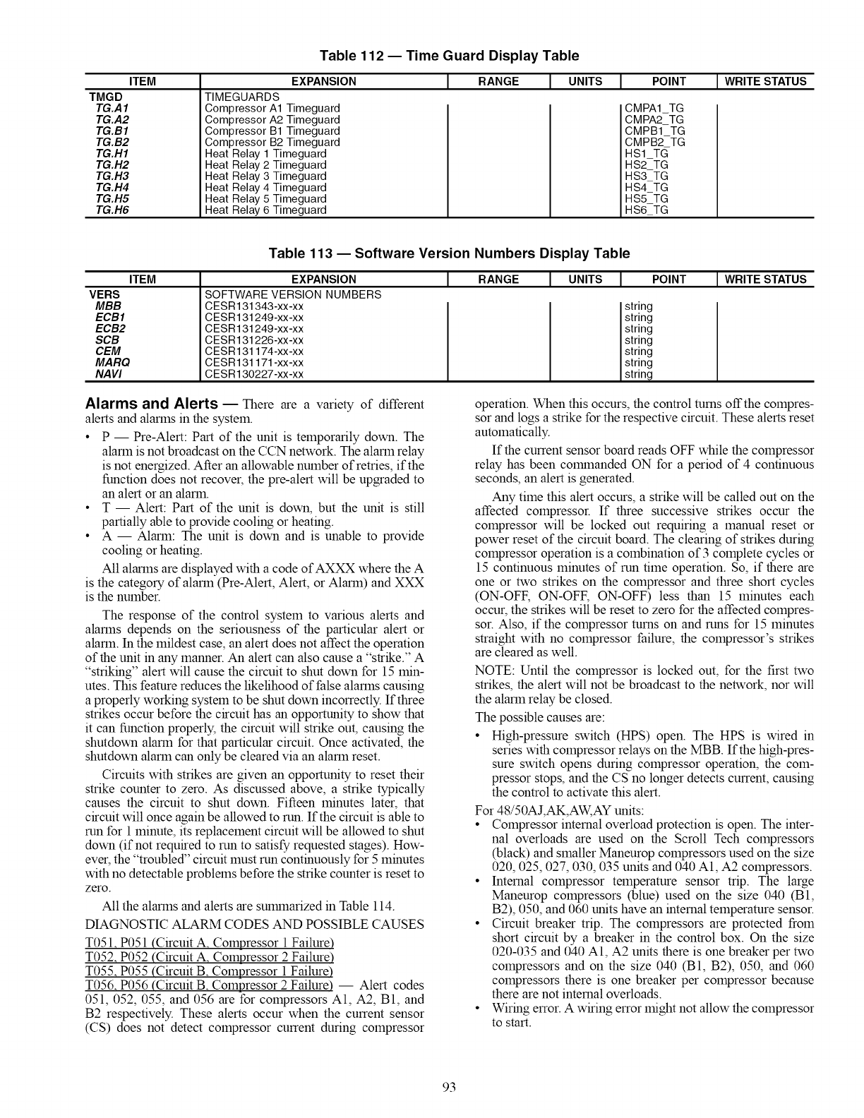
ITEM
TMGD
TG.A1
TG.A2
TG.B1
TG.B2
TG.H1
TG.H2
TG.H3
TG.H4
TG.H5
TG.H6
Table 112 -- Time Guard Display Table
EXPANSION
TIMEGUARDS
Compressor A1 Timeguard
Compressor A2 Timeguard
Compressor B1 Timeguard
Compressor B2 Timeguard
Heat Relay 1 Timeguard
Heat Relay 2 Timeguard
Heat Relay 3 Timeguard
Heat Relay 4 Timeguard
Heat Relay 5 Timeguard
Heat Relay 6 Timeguard
IRANGE I UNITS I POINT I WRITE STATUS
CMPA1 TG
CMPA2 TG
CMPB1 TG
CMPB2 TG
HS1TC_
HS2TG
HS3TG
HS4TG
HS5TG
HS6TG
ITEM
VERS
MBB
ECB1
ECB2
SCB
CEM
MARQ
NAW
Table 113 -- Software Version Numbers Display Table
I RANGE I UNITSI POINT IWRITESTATUS
EXPANSION
SOFTWARE VERSION NUMBERS
CESR131343-xx-xx
CESR131249-xx-xx
CESR131249-xx-xx
CESR131226-xx-xx
CESR131174-xx-xx
CESR131171 -xx-xx
CESR130227-xx-xx
string
string
string
string
string
string
string
Alarms and Alerts EThere are a variety of different
alerts and alarms in the system.
• P -- Pre-Alert: Part of the unit is temporarily down. The
alarm is not broadcast on the CCN network. The alarm relay
is not energized. After an allowable number of retries, if the
function does not recover, the pre-alert will be upgraded to
an alert or an alarm.
•T -- Alert: Part of the unit is down, but the unit is still
partially able to provide cooling or heating.
• A -- Alarm: The unit is down and is unable to provide
cooling or heating.
All alarms are displayed with a code of AXXX where the A
is the category of alarm (Pre-Alert, Alert, or Alarm) and XXX
is the number.
The response of the control system to various alerts and
alarms depends on the seriousness of the particular alert or
alarm. In the mildest case, an alert does not affect the operation
of the unit in any manner. An alert can also cause a "strike." A
"striking" alert will cause the circuit to shut down for 15 min-
utes. This feature reduces the likelihood of false alarms causing
a properly working system to be shut down incorrectly. If three
strikes occur before the circuit has an opportunity to show that
it can function properly, the circuit will strike out, causing the
shutdown alarm for that particular circuit. Once activated, the
shutdown alarm can only be cleared via an alarm reset.
Circuits with strikes are given an opportunity to reset their
strike counter to zero. As discussed above, a strike typically
causes the circuit to shut down. Fifteen minutes later, that
circuit will once again be allowed to run. If the circuit is able to
run for 1 minute, its replacement circuit will be allowed to shut
down (if not required to run to satisfy requested stages). How-
ever, the "troubled" circuit must run continuously for 5 minutes
with no detectable problems before the strike counter is reset to
zero.
All the alarms and alerts are SUlrunarized in Table 114.
DIAGNOSTIC ALARM CODES AND POSSIBLE CAUSES
T051. P051 (Circuit A. Compressor 1 Failure)
T052. P052 (Circuit A. Compressor 2 Failure)
T055. P055 (Circuit B. Compressor 1 Failure)
T056. P056 (Circuit B. Compressor 2 Failure) -- Alert codes
051,052, 055, and 056 are for compressors A1, A2, B1, and
B2 respectively. These alerts occur when the current sensor
(CS) does not detect compressor current during compressor
operation. When this occurs, the control turns offthe compres-
sor and logs a strike for the respective circuit. These alerts reset
automatically.
If the current sensor board reads OFF while the compressor
relay has been COlrunanded ON for a period of 4 continuous
seconds, an alert is generated.
Any time this alert occurs, a strike will be called out on the
affected compressor. If three successive strikes occur the
compressor will be locked out requiring a manual reset or
power reset of the circuit board. The clearing of strikes during
compressor operation is a combination of 3 complete cycles or
15 continuous minutes of run time operation. So, if there are
one or two strikes on the compressor and three short cycles
(ON-OFF, ON-OFF, ON-OFF) less than 15 minutes each
occur, the strikes will be reset to zero for the affected compres-
sor. Also, if the compressor turns on and runs for 15 minutes
straight with no compressor failure, the compressor's strikes
are cleared as well.
NOTE: Until the compressor is locked out, for the first two
strikes, the alert will not be broadcast to the network, nor will
the alarm relay be closed.
The possible causes are:
• High-pressure switch (HPS) open. The HPS is wired in
series with compressor relays on the MBB. If the high-pres-
sure switch opens during compressor operation, the com-
pressor stops, and the CS no longer detects current, causing
the control to activate this alert.
For 48/50AJ,AK,AW, AY units:
•Compressor internal overload protection is open. The inter-
nal overloads are used on the Scroll Tech compressors
(black) and smaller Maneurop compressors used on the size
020, 025, 027, 030, 035 units and 040 A1, A2 compressors.
• Internal compressor temperature sensor trip. The large
Maneurop compressors (blue) used on the size 040 (B1,
B2), 050, and 060 units have an internal temperature sensor.
• Circuit breaker trip. The compressors are protected from
short circuit by a breaker in the control box. On the size
020-035 and 040 A1, A2 units there is one breaker per two
compressors and on the size 040 (B1, B2), 050, and 060
compressors there is one breaker per compressor because
there are not internal overloads.
• Wiring error. A wiring error might not allow the compressor
to start.
93
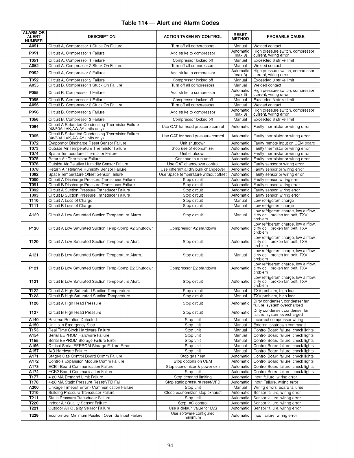
ALARM OR
ALERT
NUMBER
A051
P051
T051
A052
P052
T052
A055
P055
T055
A056
P056
T056
T064
T065
T072
T073
T074
T075
T076
T078
T082
T090
T091
T092
T093
Tl10
Tlll
A120
P120
T120
A121
P121
T121
T122
T123
T126
T127
A140
A150
T153
A154
T155
A156
A157
A171
A172
A173
A174
T177
T178
A200
T210
T211
T220
T221
T229
Table 114 -- Alert and Alarm Codes
DESCRIPTION
Circuit A, Compressor 1 Stuck On Failure
Circuit A, Compressor 1 Failure
Circuit A, Compressor 1 Failure
Circuit A, Compressor 2 Stuck On Failure
Circuit A, Compressor 2 Failure
Circuit A, Compressor 2 Failure
Circuit B, Compressor 1 Stuck On Failure
Circuit B, Compressor 1 Failure
Circuit B, Compressor 1 Failure
Circuit B, Compressor 2 Stuck On Failure
Circuit B, Compressor 2 Failure
Circuit B, Compressor 2 Failure
Circuit A Saturated Condensing Thermistor Failure
(48/50AJ,AK,AW,AY units only)
Circuit B Saturated Condensing Thermistor Failure
(48/50AJ,AK,AW,AY units only)
Evaporator Discharge Reset Sensor Failure
Outside Air Temperature Thermistor Failure
Space Temperature Thermistor Failure
Return Air Thermistor Failure
Outside Air Relative Humidity Sensor Failure
Return Air Relative Humidity Sensor Failure
Space Temperature Offset Sensor Failure
Circuit A Discharge Pressure Transducer Failure
Circuit B Discharge Pressure Transducer Failure
Circuit A Suction Pressure Transducer Failure
Circuit B Suction Pressure Transducer Failure
Circuit A Loss of Charge
Circuit B Loss of Charge
Circuit A Low Saturated Suction Temperature Alarm.
Circuit A Low Saturated Suction Temp-Comp A2 Shutdown
Circuit A Low Saturated Suction Temperature Alert.
Circuit B Low Saturated Suction Temperature Alarm.
Circuit B Low Saturated Suction Temp-Comp B2 Shutdown
Circuit B Low Saturated Suction Temperature Alert.
ACTION TAKEN BY CONTROL RESET PROBABLE CAUSE
METHOD
Turn off all compressors Manual
Automatic
Add strike to compressor (max 3)
Compressor locked off Manual
Turn off all compressors Manual
Automatic
Add strike to compressor (max 3)
Compressor locked off Manual
Turn off all compressors Manual
Automatic
Add strike to compressor (max 3)
Compressor locked off Manual
Turn off all compressors Manual
Automatic
Add strike to compressor (max 3)
Compressor locked off Manual
Use OAT for head pressure control
Welded contact
High pressure switch, compressor
current, wiring error
Exceeded 3 strike limit
Welded contact
High pressure switch, compressor
current, wiring error
Exceeded 3 strike limit
Welded contact
High pressure switch, compressor
current, wiring error
Exceeded 3 strike limit
Welded contact
High pressure switch, compressor
current, wiring error
Exceeded 3 strike limit
Automatic Faulty thermistor or wiring error
Use OAT for head pressure control Automatic
Unit shutdown Automatic
Stop use of economizer Automatic
Unit shutdown Automatic
Continue to run unit Automatic
Use OAT changeover control Automatic
Use differential dry bulb changeover Automatic
Use Space temperature without offset Automatic
Stop circuit Automatic
Stop circuit Automatic
Stop circuit Automatic
Stop circuit Automatic
Stop circuit Manual
Stop circuit Manual
Stop circuit Manual
Compressor A2 shutdown Automatic
Stop circuit Automatic
Stop circuit Manual
Compressor B2 shutdown Automatic
Circuit A High Saturated Suction Temperature
Circuit B High Saturated Suction Temperature
Circuit A High Head Pressure Stop
circuit Automatic
circuit Manual
circuit Manual
circuit Automatic
Stop
Stop
Stop
Stop circuit Automatic
Stop unit Manual
Stop unit Manual
Stop unit Manual
Stop unit Manual
Stop unit Manual
Stop unit Manual
Stop unit Manual
Stop gas heat Automatic
Stop options on CEM Automatic
Stop economizer & power exh Automatic
Stop unit Automatic
Stop demand limiting Automatic
Stop static pressure reset/VFD Automatic
Stop unit Manual
Close economizer, stop exhaust Automatic
Stop unit Automatic
Stop IAQ control Automatic
Use a default value for IAQ Automatic
Use software configured
minimum Automatic
Circuit B High Head Pressure
Reverse Rotation Detected
Unit is in Emergency Stop
Real Time Clock Hardware Failure
Serial EEPROM Hardware Failure
Serial EEPROM Storage Failure Error
Critical Serial EEPROM Storage Failure Error
A/D Hardware Failure
Staged Gas Control Board Comm Failure
Controls Expansion Module Comm Failure
ECB1 Board Communication Failure
ECB2 Board Communication Failure
4-20 MA Demand Limit Failure
4-20 MA Static Pressure ResetNFD Fail
Linkage Timeout Error - Communication Failure
Building Pressure Transducer Failure
Static Pressure Transducer Failure
Indoor Air Quality Sensor Failure
Outdoor Air Quality Sensor Failure
Economizer Minimum Position Override Input Failure
Faulty thermistor or wiring error
Faulty remote input on CEM board
Faulty thermistor or wiring error
Faulty thermistor or wiring error
Faulty thermistor or wiring error
Faulty sensor or wiring error
Faulty sensor or wiring error
Faulty sensor or wiring error
Faulty sensor, wiring error
Faulty sensor, wiring error
Faulty sensor, wiring error
Faulty sensor, wiring error
Low refrigerant charge
Low refrigerant charge
Low refrigerant charge, low airflow,
dirty coil, broken fan belt, TXV
problem
Low refrigerant charge, low airflow,
dirty coil, broken fan belt, TXV
problem
Low refrigerant charge, low airflow,
dirty coil, broken fan belt, TXV
problem
Low refrigerant charge, low airflow,
dirty coil, broken fan belt, TXV
problem
Low refrigerant charge, low airflow,
dirty coil, broken fan belt, TXV
problem
Low refrigerant charge, low airflow,
dirty coil, broken fan belt, TXV
problem
TXV problem, high load.
TXV problem, high load.
Dirty condenser, condenser fan
failure, system overcharged
Dirty condenser, condenser fan
failure, system overcharged
Incorrect compressor wiring
External shutdown command
Control Board failure, check lights
Control Board failure, check lights
Control Board failure, check lights
Control Board failure, check lights
Control Board failure, check lights
Control Board failure, check lights
Control Board failure, check lights
Control Board failure, check lights
Control Board failure, check lights
Input failure, wiring error
Input Failure, wiring error
Wiring errors, board failures
Sensor failure, wiring error
Sensor failure, wiring error
Sensor failure, wiring error
Sensor failure, wiring error
Input failure, wiring error
94
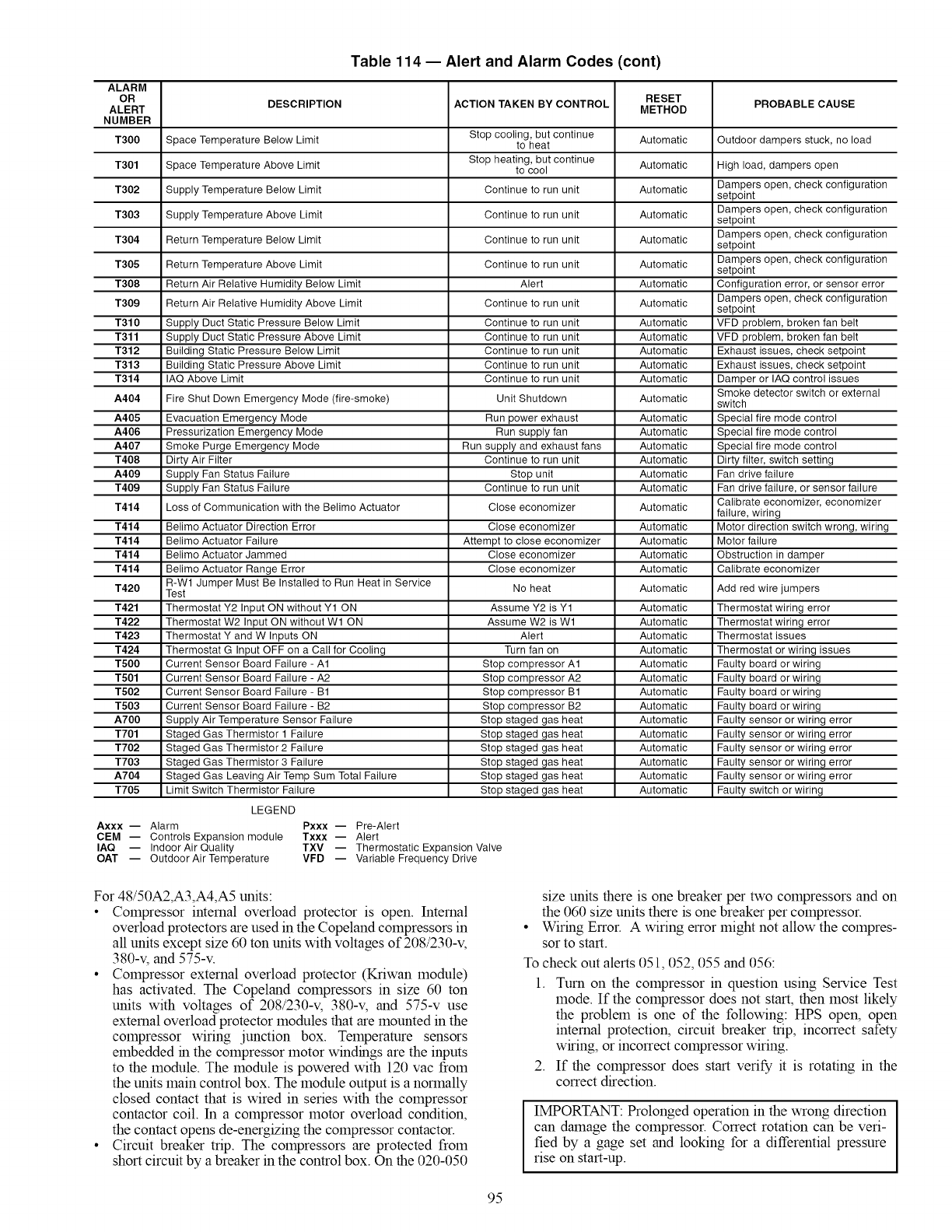
Table 114 -- Alert and Alarm Codes (cont)
ALARM
OR RESET
DESCRIPTION ACTION TAKEN BY CONTROL PROBABLE CAUSE
ALERT METHOD
NUMBER
T300 Space Temperature Below Limit Stop cooling, but continue
to heat Automatic Outdoor dampers stuck, no load
T301 Space Temperature Above Limit Stop heating, but continue
to cool Automatic High load, dampers open
Dampers open, check configuration
T302 Supply Temperature Below Limit Continue to run unit Automatic setpoint
Dampers open, check configuration
T303 Supply Temperature Above Limit Continue to run unit Automatic setpoint
Dampers open, check configuration
T304 Return Temperature Below Limit Continue to run unit Automatic setpoint
Dampers open, check configuration
T305 Return Temperature Above Limit Continue to run unit Automatic setpoint
T308 Return Air Relative Humidity Below Limit Alert Automatic Configuration error, or sensor error
Dampers open, check configuration
T309 Return Air Relative Humidity Above Limit Continue to run unit Automatic setpoint
T310 Supply Duct Static Pressure Below Limit Continue to run unit Automatic VFD problem, broken fan belt
T311 Supply Duct Static Pressure Above Limit Continue to run unit Automatic VFD problem, broken fan belt
T312 Building Static Pressure Below Limit Continue to run unit Automatic Exhaust issues, check setpoint
T313 Building Static Pressure Above Limit Continue to run unit Automatic Exhaust issues, check setpoint
T314 IAQ Above Limit Continue to run unit Automatic Damper or IAQ control issues
Smoke detector switch or external
A404 Fire Shut Down Emergency Mode (fire-smoke) Unit Shutdown Automatic switch
A405 Evacuation Emergency Mode Run power exhaust Automatic Special fire mode control
A406 Pressurization Emergency Mode Run supply fan Automatic Special fire mode control
A407 Smoke Purge Emergency Mode Run supply and exhaust fans Automatic Special fire mode control
T408 Dirty Air Filter Continue to run unit Automatic Dirty filter, switch setting
A409 Supply Fan Status Failure Stop unit Automatic Fan drive failure
T409 Supply Fan Status Failure Continue to run unit Automatic Fan drive failure, or sensor failure
T414 Loss of Communication with the Belimo Actuator Close economizer Automatic Calibrate economizer, economizer
failure, wiring
T414 Belimo Actuator Direction Error Close economizer Automatic Motor direction switch wrong, wiring
T414 Belimo Actuator Failure Attempt to close economizer Automatic Motor failure
T414 Belimo Actuator Jammed Close economizer Automatic Obstruction in damper
T414 Belimo Actuator Range Error Close economizer Automatic Calibrate economizer
R-W1 Jumper Must Be Installed to Run Heat in Service
T420 Test No heat Automatic Add red wire jumpers
T421 Thermostat Y2 Input ON without Y1 ON Assume Y2 is Y1 Automatic Thermostat wiring error
T422 Thermostat W2 Input ON without W1 ON Assume W2 is W1 Automatic Thermostat wiring error
T423 Thermostat Y and W Inputs ON Alert Automatic Thermostat issues
T424 Thermostat G Input OFF on a Call for Cooling Turn fan on Automatic Thermostat or wiring issues
T500 Current Sensor Board Failure - A1 Stop compressor A1 Automatic Faulty board or wiring
T501 Current Sensor Board Failure - A2 Stop compressor A2 Automatic Faulty board or wiring
T502 Current Sensor Board Failure - B1 Stop compressor B1 Automatic Faulty board or wiring
T503 Current Sensor Board Failure - B2 Stop compressor B2 Automatic Faulty board or wiring
A700 Supply Air Temperature Sensor Failure Stop staged gas heat Automatic Faulty sensor or wiring error
T701 Staged Gas Thermistor 1 Failure Stop staged gas heat Automatic Faulty sensor or wiring error
T702 Staged Gas Thermistor 2 Failure Stop staged gas heat Automatic Faulty sensor or wiring error
T703 Staged Gas Thermistor 3 Failure Stop staged gas heat Automatic Faulty sensor or wiring error
A704 Staged Gas Leaving Air Temp Sum Total Failure Stop staged gas heat Automatic Faulty sensor or wiring error
T705 Limit Switch Thermistor Failure Stop staged gas heat Automatic Faulty switch or wiring
LEGEND
Axxx- Alarm Pxxx- Pre-Alert
CEM -- Controls Expansion module Txxx -- Alert
IAQ -- Indoor Air Quality TXV -- Thermostatic Expansion Valve
OAT -- Outdoor Air Temperature VFD -- Variable Frequency Drive
For 48/50A2,A3,A4,A5 units:
• Compressor internal overload protector is open. Internal
overload protectors are used in the Copeland compressors in
all units except size 60 ton units with voltages of 208/230-v,
380-v, and 575-v.
• Compressor external overload protector (Kriwan module)
has activated. The Copeland compressors in size 60 ton
units with voltages of 208/230-v, 380-v, and 575-v use
external overload protector modules that are mounted in the
compressor wiring junction box. Temperature sensors
embedded in the compressor motor windings are the inputs
to the module. The module is powered with 120 vac from
the units main control box. The module output is a normally
closed contact that is wired in series with the compressor
contactor coil. In a compressor motor overload condition,
the contact opens de-energizing the compressor contactor.
• Circuit breaker trip. The compressors are protected from
short circuit by a breaker in the control box. On the 020-050
size units there is one breaker per two compressors and on
the 060 size units there is one breaker per compressor.
Wiring Error. A wiring error might not allow the compres-
sor to start.
To check out alerts 051,052, 055 and 056:
1. Turn on the compressor in question using Service Test
mode. If the compressor does not start, then most likely
the problem is one of the following: HPS open, open
internal protection, circuit breaker trip, incorrect safety
wiring, or incorrect compressor wiring.
2. If the compressor does start verify it is rotating in the
correct direction.
IMPORTANT: Prolonged operation in the wrong direction
can damage the compressor. Correct rotation can be veri-
fied by a gage set and looking for a differential pressure
rise on start-up.
95
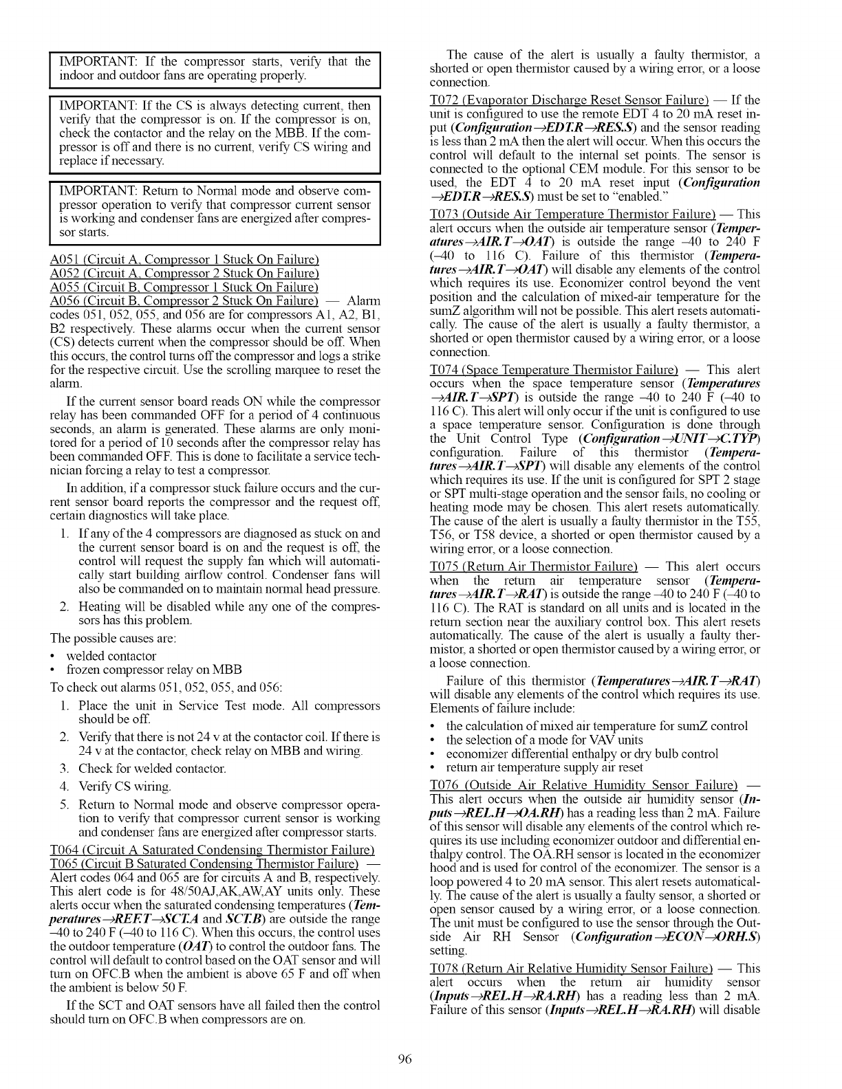
IMPORTANT:If thecompressorstarts,verifythat the
indoor and outdoor fans are operating properly.
IMPORTANT: If the CS is.always detecting current, then
verify that the compressor is on. If the compressor is on,
check the contactor and the relay on the MBB. If the com-
pressor is off and there is no current, verify CS wiring and
replace if necessary.
IMPORTANT: Return to Normal mode and observe com-
pressor operation to verify that compressor current sensor
is working and condenser fans are energized after compres-
sor starts.
A051 (Circuit A. Compressor 1 Stuck On Failure)
A052 (Circuit A. Compressor 2 Stuck On Failure)
A055 (Circuit B. Compressor 1 Stuck On Failure)
A056 (Circuit B. Compressor 2 Stuck On Failure) -- Alarm
codes 051, 052, 055, and 056 are for compressors A1, A2, B1,
B2 respectively. These alarms occur when the current sensor
(CS) detects current when the compressor should be off. When
this occurs, the control turns offthe compressor and logs a strike
for the respective circuit. Use the scrolling marquee to reset the
alarm.
If the current sensor board reads ON while the compressor
relay has been colnmanded OFF for a period of 4 continuous
seconds, an alarm is generated. These alarms are only moni-
tored for a period of 10 seconds after the compressor relay has
been colnmanded OFE This is done to facilitate a service tech-
nician forcing a relay to test a compressor.
In addition, ifa compressor stuck failure occurs and the cur-
rent sensor board reports the compressor and the request off,
certain diagnostics will take place.
1. If any of the 4 compressors are diagnosed as stuck on and
the current sensor board is on and the request is off, the
control will request the supply fan which will automati-
cally start building airflow control. Condenser fans will
also be COlrnnanded on to maintain normal head pressure.
2. Heating will be disabled while any one of the compres-
sors has this problem.
The possible causes are:
•welded contactor
• frozen compressor relay on MBB
To check out alarms 051,052, 055, and 056:
1. Place the unit in Service Test mode. All compressors
should be off.
2. Verify that there is not 24 v at the contactor coil. If there is
24 v at the contactor, check relay on MBB and wiring.
3. Check for welded contactor.
4. Verify CS wiring.
5. Return to Normal mode and observe compressor opera-
tion to verify that compressor current sensor is working
and condenser fans are energized after compressor starts.
T064 (Circuit A Saturated Condensing Thermistor Failure)
T065 (Circuit B Saturated Condensing Thermistor Failure) --
Alert codes 064 and 065 are for circuits A and B, respectively.
This alert code is for 48/50AJ,AK,AW, AY units only. These
alerts occur when the saturated condensing temperatures (Tem-
peratures-¢REET-cSCT.A and SCT.B) are outside the range
-40 to 240 F (-40 to 116 C). When this occurs, the control uses
the outdoor temperature (OAT) to control the outdoor fans. The
control will default to control based on the OAT sensor and will
turn on OFC.B when the ambient is above 65 F and off when
the ambient is below 50 E
If the SCT and OAT sensors have all failed then the control
should turn on OFC.B when compressors are on.
The cause of the alert is usually a faulty thermistor, a
shorted or open thermistor caused by a wiring error, or a loose
connection.
T072 (Evaporator Discharge Reset Sensor Failure) -- If the
unit is configured to use the remote EDT 4 to 20 mA reset in-
put ((bnfiguration--cEDT.R--cRES.S) and the sensor reading
is less than 2 mA then the alert will occur. When this occurs the
control will default to the internal set points. The sensor is
connected to the optional CEM module. For this sensor to be
used, the EDT 4 to 20 mA reset input ((bnfiguration
-+EDT.R-+RES.S) must be set to "enabled."
T073 (Outside Air Temperature Thermistor Failure) -- This
alert occurs when the outside air temperature sensor (Temper-
atures-+AIR.T_OAT) is outside the range -40 to 240 F
(-40 to 116 C). Failure of this thermistor (Tempera-
tures-+AIR.T_OAT) will disable any elements of the control
which requires its use. Economizer control beyond the vent
position and the calculation of mixed-air temperature for the
sumZ algorithin will not be possible. This alert resets automati-
cally. The cause of the alert is usually a faulty thermistor, a
shorted or open thermistor caused by a wiring error, or a loose
connection.
T074 (Space Temperature Thermistor Failure) -- This alert
occurs when the space temperature sensor (Temperatures
---)AIR.T--+SPT) is outside the range -40 to 240 F (-40 to
116 C). This alert will only occur if the unit is configured to use
a space temperature sensor. Configuration is done through
the Unit Control Type (Configuration--_UNIT-+CTYP)
configuration. Failure of this thermistor (Tempera-
tures--+AIR.T--+SPT) will disable any elements of the control
which requires its use. If the unit is configured for SPT 2 stage
or SPT multi-stage operation and the sensor fails, no cooling or
heating mode may be chosen. This alert resets automatically.
The cause of the alert is usually a faulty thermistor in the T55,
T56, or T58 device, a shorted or open thermistor caused by a
wiring error, or a loose connection.
T075 (Return Air Thermistor Failure) -- This alert occurs
when the remm air temperature sensor (Tempera-
tures--)AIR. T--cRAT) is outside the range -40 to 240 F (-40 to
116 C). The RAT is standard on all units and is located in the
return section near the auxiliary control box. This alert resets
automatically. The cause of the alert is usually a faulty ther-
mistor, a shorted oropen thermistor caused by a wiring error, or
a loose connection.
Failure of this thermistor (Temperatures--)AIR.T---_RAT)
will disable any elements of the control which requires its use.
Elements of failure include:
• the calculation of mixed air temperature for sumZ control
• the selection of a mode for VAV units
• economizer differential enthalpy or dry bulb control
• return air temperature supply air reset
T076 (Outside Air Relative Humidity Sensor Failure) --
This alert occurs when the outside air humidity sensor (In-
puts--cREL.H_OA.RH) has a reading less than 2 mA. Failure
of this sensor will disable any elements of the control which re-
quires its use including economizer outdoor and differential en-
thalpy control. The OA.RH sensor is located in the economizer
hood and is used for control of the economizer. The sensor is a
loop powered 4 to 20 mA sensor. This alert resets automatical-
ly. The cause of the alert is usually a faulty sensor, a shorted or
open sensor caused by a wiring error, or a loose connection.
The unit must be configured to use the sensor through the Out-
side Air RH Sensor ((bnfiguration-cE(ON_ORH.S)
setting.
T078 (Return Air Relative Humidity Sensor Failure) -- This
alert occurs when the remm air humidity sensor
(Inputs--cRELH---_RA.RH) has a reading less than 2 mA.
Failure of this sensor (Inputs--cREL.H--cRA.RH) will disable
96
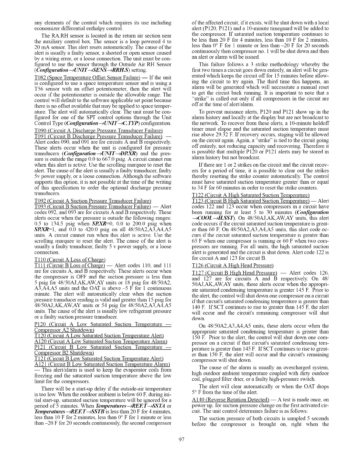
any elements of the control which requires its use including
economizer differential enthalpy control.
The RA.RH sensor is located in the return air section near
the auxiliary control box. The sensor is a loop powered 4 to
20 mA sensor. This alert resets automatically. The cause of the
alert is usually a faulty sensor, a shorted or open sensor caused
by a wiring error, or a loose connection. The unit must be con-
figured to use the sensor through the Outside Air RH Sensor
(Configuration--cUNIT--+SENS--+RRI-I.S) setting.
T082 (Space Temperature Offset Sensor Failure) -- If the unit
is configured to use a space temperature sensor and is using a
T56 sensor with an offset potentiometer, then the alert will
occur if the potentiometer is outside the allowable range. The
control will default to the software applicable set point because
there is no offset available that may be applied to space temper-
amre. The alert will automatically clear. The unit must be con-
figured for one of the SPT control options through the Unit
Control Type ((bnfiguration-+UNIT_C TYP) configuration.
T090 (Circuit A Discharge Pressure Transducer Failure)
T091 (Circuit B Discharge Pressure Transducer Failure) --
Alert codes 090, and 091 are for circuits Aand B respectively.
These alerts occur when the unit is configured for pressure
transducers ((bnfiguration--cUNIT---_DRXR) and the pres-
sure is outside the range 0.0 to 667.0 psig. Acircuit cannot run
when this alert is active. Use the scrolling marquee to reset the
alert. The cause of the alert is usually a faulty transducer, faulty
5v power supply, or a loose connection. Although the software
supports this option, it is not possible at the time of the writing
of this specification to order the optional discharge pressure
transducers.
T092 (Circuit A Suction Pressure Transducer Failure)
T093 (Circuit B Suction Pressure Transducer Failure) -- Alert
codes 092, and 093 are for circuits A and B respectively. These
alerts occur when the pressure is outside the following ranges:
0.5 to 134.5 psig when SRXR=O, 0.0 to 200.0 psig when
SRXR=I, and 0.0 to 420.0 psig on all 48/50A2,A3,A4,A5
units. A circuit cannot mn when this alert is active. Use the
scrolling marquee to reset the alert. The cause of the alert is
usually a faulty transducer, faulty 5 v power supply, or a loose
connection.
T110 (Circuit A Loss of Charge)
Till (Circuit B Loss of Charge) -- Alert codes 110, and 111
are for circuits A, and B respectively. These alerts occur when
the compressor is OFF and the suction pressure is less than
5 psig for 48/50AJ,AK,AW, AY units or 18 psig for 48/50A2,
A3,A4,A5 units and the OAT is above -5 F for 1 continuous
minute. The alert will automatically clear when the suction
pressure transducer reading is valid and greater than 15 psig for
48/50AJ,AK,AW, AY units or 54 psig for 48/50A2,A3,A4,A5
units. The cause of the alert is usually low refrigerant pressure
or a faulty suction pressure transducer.
P120 (Circuit A Low Saturated Suction Temperature --
Compressor A2 Shutdown)
T120 (Circuit A Low Saturated Suction Temperature Alert)
A120 (Circuit A Low Saturated Suction Temperature Alarm)
P121 (Circuit B Low Saturated Suction Temperature --
Compressor B2 Shutdown)
T121 (Circuit B Low Saturated Suction Temperature Alert)
A121 (Circuit B Low Saturated Suction Temperature Alarm)
-- This alert/alarm is used to keep the evaporator coils from
freezing and the saturated suction temperature above the low
lfinit for the compressors.
There will be a start-up delay if the outside-air temperature
is too low. When the outdoor ambient is below 60 F, during ini-
tial start-up, saturated suction temperature will be ignored for a
period of 5 minutes. When Temperatures--cREET--cSSTA or
Temperatures--cREET--cSSTB is less than 20 F for 4 minutes,
less than 10 F for 2 minutes, less than 0° F for 1 minute or less
than -20 F for 20 seconds continuously, the second compressor
of the affected circuit, if it exists, will be shut down with a local
alert (P120, P121) and a 10-minute thneguard will be added to
the compressor. If saturated suction temperature continues to
be less than 20 F for 4 minutes, less than 10 F for 2 minutes,
less than 0 °F for 1 minute or less than -20 F for 20 seconds
continuously then compressor no. 1 will be shut down and then
an alert or alarm will be issued.
This failure follows a 3 strike methodology whereby the
first two times a circuit goes down entirely, an alert will be gen-
erated which keeps the circuit off for 15 minutes before allow-
ing the circuit to try again. The third time this happens, an
alarm will be generated which will necessitate a manual reset
to get the circuit back running. It is hnportant to note that a
"strike" is called out only if all compressors in the circuit are
off at the time of alert!alarm.
To prevent nuisance alerts, P120 and P121 show up in the
alarm history and locally at the display but are not broadcast to
the network. To recover from these alerts, a 10-minute holdoff
timer must elapse and the saturated suction temperature must
rise above 29.32 F. If recovery occurs, staging will be allowed
on the circuit again. Again, a "strike" is tied to the circuit going
off entirely, not reducing capacity and recovering. Therefore it
is possible that multiple P120 or P121 alerts may be stored in
alarm history but not broadcast.
If there are 1 or 2 strikes on the circuit and the circuit recov-
ers for a period of thne, it is possible to clear out the strikes
thereby resetting the strike counter automatically. The control
must have saturated suction temperature greater than or equal
to 34 F for 60 minutes in order to reset the strike counters.
T122 (Circuit A High Saturated Suction Temperature)
T123 (Circuit B High Saturated Suction Temperature) -- Alert
codes 122 and 123 occur when compressors in a circuit have
been running for at least 5 to 30 minutes ((bnfiguration
_'OOL-+H.SSI). On 48/50AJ,AK,AW, AY units, this alert
code occurs if the circuit saturated suction temperature is great-
er than 60 E On 48/50A2,A3,A4,A5 units, this alert code oc-
curs if the circuit saturated suction temperature is greater than
65 F when one compressor is running or 60 F when two com-
pressors are running. For all units, the high saturated suction
alert is generated and the circuit is shut down. Alert code 122 is
for circuit A and 123 for circuit B.
T126 (Circuit A High Head Pressure)
T127 (Circuit B High Head Pressure) -- Alert codes 126,
and 127 are for circuits A and B respectively. On 48/
50AJ,AK,AW, AY units, these alerts occur when the appropri-
ate saturated condensing temperature is greater 145 E Prior to
the alert, the control will shut down one compressor on a circuit
if that circuit's saturated condensing temperature is greater than
140 E If SCT continues to rise to greater than 145 F, the alert
will occur and the circuit's remaining compressor will shut
down.
On 48/50A2,A3,A4,A5 units, these alerts occur when the
appropriate saturated condensing temperature is greater than
150 E Prior to the alert, the control will shut down one com-
pressor on a circuit if that circuit's saturated condensing tem-
perature is greater than 145 F. IfSCT continues to rise to great-
er than 150 F, the alert will occur and the circuit's remaining
compressor will shut down.
The cause of the alarm is usually an overcharged system,
high outdoor ambient temperature coupled with dirty outdoor
coil, plugged filter drier, or a faulty high-pressure switch.
The alert will clear automatically or when the OAT drops
5° F from the time of the alert.
A140 (Reverse Rotation Detected) -- A test is made once, on
power up, for suction pressure change on the first activated cir-
cuit. The unit control determines failure is as follows:
The suction pressure of both circuits is sampled 5 seconds
before the compressor is brought on, right when the
97
com.pressorisbroughtonand5secondsafterwards.Therateof
suctionpressurechangefrom5secondsbeforethecompressor
isbroughtontowhenthecompressorisbroughtoniscalculat-
ed.Thentherateof suctionpressurechangefromwhenthe
compressorisbroughtonto5secondsafterwardsiscalculated.
Withtheaboveinformation,thetestforreverserotationis
made.If thesuctionpressurechange5secondsaftercompres-
sionisgreaterthanthesuctionpressurechange5secondsbe-
forecompression- 1.25,thenthereisareverserotationerror.
Thisalarmwilldisablemechanicalcoolingandwillrequire
amanualreset.Thisalarmmaybedisabledoncethereverse
rotationcheckhasbeenverifiedbysettingConfiguration--+
COOL---_REV.R=Yes.
A150 (Unit is in Emergency Stop) -- If the fire safety input
condition occurs to indicate a fire or smoke condition, then
Alarm code 150 will occur and the unit will be ilrnnediately
stopped. Through separate inputs the unit can be put into purge,
evacuation, and pressurization. This requires a manual reset.
If the CCN point name "EMSTOP" in the System table is
set to emergency stop, the unit will shut down immediately and
broadcast an alarm back to the CCN indicating that the unit is
down. This alarm will clear when the variable is set back to
"enable."
T153 (Real Time Clock Hardware Failure) -- A problem has
been detected with the real timeclock on the MBB. Try reset-
ting the power and check the indicator lights. If the alert contin-
ues, the board should be replaced.
A154 (Serial EEPROM Hardware Failure) -- A problem has
been detected with the EEPROM on the MBB. Try resetting
the power and check the indicator lights. If the alarm continues,
the board should be replaced.
T155 (Serial EEPROM Storage Failure Error) -- A problem
has been detected with the EEPROM storage on the MBB. Try
resetting the power and check the indicator lights. If the alert
continues, the board should be replaced.
A156 (Critical Serial EEPROM Storage Failure Error) -- A
problem has been detected with the EEPROM storage on the
MBB. Try resetting the power and check the indicator lights. If
the alarm continues, the board should be replaced.
A157 (A!D Hardware Failure) -- A problem has been detected
with A/D conversion on the boards. Try resetting the power
and check the indicator lights. If the alarm continues, the board
should be replaced.
A171 (Staged Gas Control Board Comm Failure) -- This
alarm indicates that there are communications problems with
the staged gas heat control board, which is located in the gas
section on units equipped with staged gas heat. If this alarm
occurs, the staged gas heat will be disabled. The alarm will
automatically reset.
A172 (Controls Expansion Module Comm Failure) -- This
alarm indicates that there are communications problems with
the controls expansion board. All functions performed by the
CEM will stop, which can include demand limit, reset, fire
control modes, and the fan stares switch. The alarm will auto-
matically reset.
A173 (ECB1 Board Communication Failure) -- This alarm
indicates that there are colrnnunications problems with the
economizer control board. This will result in the economizer
and the power exhaust not working and the dampers to be fully
closed. The exhaust fans will stop. The alarm will automati-
cally reset.
A174 (ECB2 Board Communication Failure) -- This alarm
indicates that there are colrnnunications problems with the
ECB2 which controls the VAV unit indoor fan inverter speed
and hot gas bypass on CV and VAV units. Because the control
of the fan is critical to unit operation, the unit will be stopped.
The alarm will automatically reset.
T177 (4-20 mA Demand Limit Failure) -- This alert indi-
cates a problem with the optional remote 4 to 20 mA demand
limit signal (Inputs_4-20--cDLM.M) that is connected to the
CEM module (if the signal reads less than 2 mA). If this
occurs, then demand limiting will be disabled. The unit must
be configured for 4 to 20 mA Demand Limiting using the
Demand Limit Select (Configuration--cDMD.L -¢DM.L.S).
T178 (4-20 mA Static Pressure Reset/VFD Failure) -- If this
transducer fails (if the signal reads less than 2 mA on the input
of the CEM module), and the unit is configured to perform
static pressure reset or remote control of the supply fan VFD
with this transducer, no static pressure reset or VFD control
will be performed and an alert will be generated. Recovery is
automatic. Reason for error is either a faulty sensor, wiring
error, or damaged input on the CEM control board.
A200 (Linkage Timeout Error-- Comm Failure) -- If link-
age is established via the CCN with ComfortlD TM terminals, a
5-minute tflneout on loss of conununication will be monitored.
If 5 minutes expires since the last colrnnunication from a VAV
Linkage Master, the unit will remove the link and flag the alert.
When the rooftop looses its link, the temperature and set points
are derived locally. Recovery is automatic on re-establisiunent
of colrnnunications. Reason for failure may be wiring error, too
much bus activity, or damaged 485 drivers.
T210 (Building Pressure Transducer Failure) -- The building
pressure transducer (Pressures-+AIR.P-+BP) fails if the
signal from the 4to 20 mA building pressure transducer (used
to control the power exhaust fans and the building pressure) is
below 2 mA. If the alert occurs, then the economizer will be
closed and the power exhaust fans mined off. This alert will
automatically reset. Check the building pressure transducer and
sensor robing. The sensor is located in the auxiliary control
box. The alert will automatically reset.
T211 (Static Pressure Transducer Failure) -- The static pres-
sure transducer (Pressures-+AIR.P-+SP) fails if the signal
from the 4 to 20 mA static pressure transducer (used to control
the VFD speed) is below 2 mA. This failure will cause the unit
to stop due to the potential damage that could occur due to
over-pressurization. Check the pressure transducer and sensor
robing. The sensor is located in the auxiliary control box. The
alert will automatically reset.
T220 (Indoor Air Quality Sensor Failure) -- The indoor air
quality sensor (Inputs---_AIR.Q---_IAQ) fails if the signal from
the 4 to 20 mA sensor is below 2 mA. If the indoor air quality
sensor fails, demand control ventilation is not possible. The
control defaults to the maximum vent position. Recovery is au-
tomatic. Reason for error is either a faulty sensor, wiring error,
or damaged input on the MBB control board.
T221 (Outdoor Air Quality Sensor Failure) -- The indoor air
quality sensor (Inputs---_AIR.Q_OAQ) fails if the signal from
the 4 to 20 mA sensor is below 2 mA. If the outdoor air quality
sensor fails, OAQ defaults to 400 ppm and demand control
ventilation will continue. Recovery is automatic. Reason for
error is either a faulty sensor, wiring error, or damaged input on
the CEM control board.
T229 (Economizer Minimum Position Ovemde Input Fail-
ure) -- If the unit is configured to use the remote position
override for the economizer and the input Econo Min. Pos.
Ovemde (Configuration--+IAQ--+AQ.SP--+IQ.O.P) input 4 to
20 mA reading is less than 2 mA then an alert will occur and
the default software minhnum position will be used for the
economizer. The alert will automatically reset.
T300 (Space Temperature Below Limit) -- If the space tem-
perature is below the configurable SPT Low Alert
Limits (occupied [Cbnfiguration---)ALLM--+SRL.O] for
5 minutes or unoccupied [Configuration--+ALLM--+SRL. U]
for 10 minutes), then an alert will be broadcast. The alert will
automatically reset.
98
T301 (Space Temperature Above Limit) -- If the space tem-
perature is above the configurable SPT High Alert
Lhnits (occupied [(bnfiguration--cALLM--cSRI-I.O] for
5 minutes or unoccupied [(bnfiguration--cALLM--cSRI-I. U]
for 10 minutes), then an alert will be broadcast. The alert will
automatically reset.
T302 (Supply Temperature Below Limit) -- If the supply-air
temperature measured by the supply temperature sensor is
below the configurable SAT LO Alert Limit/Occ ((bnfigura-
tion--cALLM--cSA.L.O) for 5 minutes or the SAT LO Alert
Lhnit/Unocc ((bnfiguration---)ALLM--cSA.L.U) for 10 min-
utes, then an alert will be broadcast.
T303 (Supply Temperature Above Limit) -- If the supply
temperature is above the configurable SAT HI Alert Lhnit Occ
((bnfiguration--cALLM--cSAI-I..O) for 5 minutes or the SAT
HI Alert Limit/Unocc ((bnfiguration--cALLM--cSA.I-I.. U) for
10 minutes, then an alert will be broadcast. The alert will
automatically reset.
T304 (Return Air Temperature Below Lhnit) -- If the return-
air temperature measured by the RAT sensor is below the
configurable RAT LO Alert Limit/Occ ((bnfiguration--€
ALLM-cRA.L.O) for 5 minutes or RAT HI Alert Lhnit!Occ
((bnfiguration--cALLM--cRA.L.U) for 10 minutes, then an
alert will be broadcast.
T305 (Return Air Temperature Above Limit) -- If the return-
air temperature is below the RAT HI Alert Limit/Occ (Config-
uration--)ALLM-+RA.I-LO) for 5 minutes or RAT HI
Alert Limit!Occ (Configuration -+ALLM-+RA.H.U) for
10 minutes, then an alert will be broadcast. The alert will
automatically reset.
T308 (Return Air Relative Humidity Below Limit) -- If the
unit is configured to use a return air relative humidity sensor
through the Return Air RH Sensor ((bnfiguration
-+UNIT-+SENS-+RRH.S) setting, and the measured level is
below the configurable RH Low Alert Limit (Configuration
--)ALLM-+R.RH.L) for 5 minutes, then the alert will occur.
The unit will continue to mn and the alert will automatically
reset.
T309 (Return Air Relative Humidity Above Limit) -- If the
unit is configured to use a return air relative humidity sensor
through the Return Air RH Sensor (Configuration
--+UNIT--+SENS--+RRI-I..S)setting, and the measured level is
above the configurable RH High Alert Limit (Configuration
--)ALLM-+R.RH.H) for 5 minutes, then the alert will occur.
Unit will continue to run and the alert will automatically reset.
T310 (Supply Duct Static Pressure Below Limit) -- If the unit
is a VAV unit with a supply duct pressure sensor and the
measured supply duct static pressure (Pressures--€
AIR.P-+SP) is below the configurable SP Low Alert Limit
(Configuration--cALLM--cSRL) for 5 minutes, then the alert
will occur. The unit will continue to mn and the alert will auto-
matically reset.
T311 (Supply Duct Static Pressure Above Limit) -- If the unit
is a VAV unit with a supply duct pressure sensor and the
measured supply duct static pressure (Pressures--€
AIR.P--cSP) is above the configurable SP Low Alert Limit
((bnfiguration--cALLM--cSRH) for 5 minutes, then the alert
will occur. The unit will continue to mn and the alert will auto-
matically reset.
T312 (Building Static Pressure Below Limit) -- If the unit is
configured to use a VFD controlled power exhaust or a modu-
lating power exhaust then a building static pressure lhnit can be
configured using the BP Low Alert Limit (Configuration
---)ALLM--cBRL). If the measured pressure (Pres-
sures---)AIR.P--cBP) is below the limit for 5 minutes then the
alert will occur.
T313 (Building Static Pressure Above Limit) -- If the unit is
configured to use a VFD controlled power exhaust or a modu-
lating power exhaust then a building static pressure lhnit can be
configured using the BP HI Alert Limit ((bnfiguration
---)ALLM--+BBH). If the measured pressure
(Pressures--cAIR.P--cBP) is above the lhnit for 5 minutes,
then the alert will occur.
T314 (IAQ Above Limit) -- If the unit is configured to use an
CO: sensor and the level (Inputs-+AIR.Q-+IAQ) is above the
configurable IAQ High Alert Limit (Configuration--_
ALLM-+IAQ.H) for 5 minutes then the alert will occur. The
unit will continue to mn and the alert will automatically reset.
A404 (Fire Shutdown Emergency Mode) -- This alarm occurs
when the fire shutdown input is active (either open or closed
depending upon its configuration). If the fire shutdown input is
energized (fire shutdown is in effect), or if two fire smoke
modes are incorrectly energized at the same thne, a fire shut-
down mode will occur. This is an emergency mode requiring
the complete shutdown of the unit. Recovery is automatic
when the inputs are no longer on.
This alarm is usually caused by an auxiliary device that is
trying to shut down the unit (e.g., smoke detector). The input
for Fire Shutdown is at Inputs-cFIRE-cFSD. The switch
logic configuration for this switch input can be found at
variable (bnfiguration-cSW.LG-cFSD.L Verify that the
configuration is set correctly, verify the wiring and auxiliary
device. This alarm resets automatically.
A405 (Evacuation Emergency Mode) -- Unit has been placed
in the fire evacuation mode by means of the external colrnnand
for evacuation (Inputs" -+FIRE-+EVA().
If the evacuation input on the CEM is energized, an evacua-
tion mode occurs which flags an alarm. This mode attempts to
lower the pressure of the space to prevent smoke from moving
into another space. This is the reverse of the Pressurization
mode. Closing the economizer, opening the return-air damper,
turning on the power exhaust, and shutting down the indoor fan
will decrease pressure in the space. Recovery is automatic
when the input is no longer on.
A406 (Pressurization Emergency Mode) -- Unit has been
placed in the fire pressurization mode by means of the External
colrunand for pressurization (Inputs'--)FIRE--+PRES).
If the pressurization input on the CEM is energized, a pres-
surization mode occurs which flags an alarm. This mode
attempts to raise the pressure of a space to prevent smoke
infiltration from another space. The space with smoke should
be in an Evacuation mode attempting to lower its pressure.
Opening the economizer, closing the return-air damper, shut-
!ing down power exhaust, and turning the indoor fan on will
increase pressure in the space. Recovery is automatic when the
input is no longer on.
A407 (Smoke PurEe Emergency Mode) -- Unit has been
placed in the fire pressurization mode by means of the external
colrnnand for pressurization (Inputs'--+FIRE -+PURG).
If the smoke purge input on the CEM is energized, a smoke
purge mode occurs which flags an alarm. This mode attempts
to draw out smoke from the space after the emergency condi-
tion. Opening the economizer, closing the return-air damper,
and turning on both the power exhaust and indoor fan will
evacuate smoke and bring in fresh air. Recovery is automatic
when the input is no longer on.
T408 (Dirty Air Filter) -- If no dirty filter switch is installed,
the switch will read "clean filter" all the thne. Therefore the
dirty filter routine runs continuously and diagnoses the input.
Because of the different possible times it takes to generate
static pressure, this routine waits 2 minutes after the fan starts
before the dirty filter switch is monitored. If the dirty filter
switch reads "dirty filter" for 2 continuous minutes, an alert is
generated. No system action is taken. This is a reminder that it
is time to change the filters in the unit. Recovery from this alert
is through a clearing of all alarms (manual) or after the dirty
filter switch reads clean for 30 continuous seconds (automatic).
99
BecausetheDirtyAirFilterswitchcanbeconfigurednor-
mallyopenedorclosed,theswitchmightbeopenorclosed.
Theconfigurationforthisswitchinputcanbefoundatvariable
Configuration--)SW.LG--)SFS.L Verify that the configura-
tion is set correctly. Verify the wiring and filter status switch.
The hose should be connected to the low side of the switch.
This alert resets automatically. The dirty filter switch is enabled
at Configuration--cUNIT-+SENS-+FL T.S.
A409 (Supply Fan Colmnanded On Sensed Off Failure)
A409 (Supply Fan Colmnanded Off Sensed On Failure)
T409 (Supply Fan Colmnanded On. Sensed Off Failure)
T409 (Supply Fan Colmnanded Off Sensed On Failure) --
Both the alert and the alarm refer to the same failure. The only
difference between the alarm and alert is that in the case where
the supply fan status configuration to shut down the unit is set
to YES ((bnfiguration--cUNIT--cSFS.S), the alarm will be
generated AND the unit will be shut down. It is possible to
configure (bnfiguration--cUNITS--+SFS.M to either aswitch
or to monitor a0.2-in. wg rise in duct pressure if the unit is
VAV with duct pressure control.
The thnings for failure for both are the same and are
illustrated in the following table:
MINIMUM ON MINIMUM OFF
UNIT TYPE/MODE TIME TIME
CV (no gas heat) 30 seconds 1 minute
CV (gas heat) 2 minutes 4 minutes
VAV (IGV/no gas heat) 2 minutes 4 minutes
VAV (VFD/no gas heat) 1 minute 1 minute
VAV (IGV/gas heat) 4 minutes 4 minutes
VAV (VFD/gas heat) 3 minutes 4 minutes
Recovery is manual. Reason for failure may be a broken fan
belt, failed fan relay or failed supply fan status switch.
T414 (Loss of Colrnnunication with Belflno Actuator) -- The
Belimo economizer motor is a digital controlled motor. The
(_l_[brtLink TM controls can monitor the status of the motor. If
there is a problem, this alert will occur. The control will attempt
to close the economizer dampers.
T414 (Belimo Actuator Direction Error) -- This alert occurs
when the economizer damper direction switch is in the wrong
position. The direction switch should be in the clockwise posi-
tion and the actuator should be mounted so that the CW face of
the actuator is accessible. Correct if necessary. This alert clears
automatically.
T414 (Belimo Actuator Failure) -- This alert occurs when the
cognnanded damper position is changing too rapidly. This alert
resets automatically.
T414 (Belimo Actuator Jalrnned) -- This alert occurs when
the control software has detected that the damper is stuck.
Check the mechanical actuation of the dampers.
T414 (Belimo Actuator Range Error) -- This alert occurs
when the economizer range of motion is less than 90 degrees.
Initiate economizer calibration (Service Test-+INDP--€
E.(;_tL) using the Service Test menu.
T420 (R-Wl Jumper Must be Installed to Run Heat in Service
Test) -- This alert occurs when a request for a heat output has
occurred yet the Wl input is not high. A jumper must be
installed between R and Wl when trying to test heat in Service
Test. The alert will clear when Service Test is exited or if
another Service Test mode is selected. Remove jumper when
done using Service Test if the unit is operating with a thermo-
stat. The jumper should only be left in place if the unit is
operating with a space temperature sensor.
T421 (Thermostat Y2 Input On without Y1 On) -- This alert
occurs in Thermostat Mode when Y2 is energized and Y1 is
not. Verify thermostat and thermostat wiring. When Y2 turns
on, the software will behave as if Y1 and Y2 are both on. When
Y2 turns off, the software will behave as if Y1 and Y2 are both
Off. This alert resets automatically when Y1 is turned on.
T422 (Thermostat W2 Input On without Wl On) -- This alert
occurs in Thermostat Mode when W2 is energized and Wl is
not. Verify thermostat and thermostat wiring. When W2 turns
on, the software will behave as if Wl and W2 are both on.
When W2 turns off, the software will behave as ifWl and W2
are both off. This alert resets automatically when Wl is turned
on.
T423 (Thermostat Y and W Inputs On) -- This alert occurs in
Thermostat Mode when Y1 or Y2 is energized shnultaneously
with Wl or W2. Verify thermostat and thermostat wiring. The
software will enter either the cooling or heating mode depend-
ing upon which input turned on first. This alert resets automati-
cally when Y1 and Y2 are not on simultaneously with Wl and
W2.
T424 (Thermostat G Input Off On a Cooling Call) -- This
alert occurs in Thermostat Mode when the fan is not requested
(G = ON) during cooling (Y1 or Y2 = ON). Verify thermostat
and thermostat wiring.
T500 (Current Sensor Board Failure - A1)
T501 (Current Sensor Board Failure - A2)
T502 (Current Sensor Board Failure - B1)
T503 (Current Sensor Board Failure- B2) -- Alert codes
500, 501,502, and 503 are for compressors A1, A2, B1, and
B2 respectively. These alerts occur when the output of the cur-
rent sensor (CS) is a constant high value. These alerts reset au-
tomatically. If the problem cannot be resolved and the CS
board must be replaced, the CS board can be temporarily dis-
abled while securing a replaced board. A CS board is disabled
by setting Configuration _'OOL--c(S.A1, (S.A2, (S.B1 or
(S.B2 to Disable.
If the current sensor board malfunctions or is not properly
connected to its assigned digital input, an alert will be generat-
ed. It takes 2 to 4 seconds to log the alert. If the alert is logged,
it stays for a minhnum of 15 seconds to provide the application
a reasonable time to catch the failure. Compressors will be not
be inhibited by this failure. Recovery is automatic. Reason for
failure may be a faulty current sensor board, incorrect wiring,
or a damaged input on the MBB control board.
A700 (Supply Air Temperature Sensor Failure) -- This alarm
indicates a failure of the sensor supply air temperature sensor
or the leaving air temperature sensor (if using hydronic heat).
This alarm occurs when the temperature sensor (Tempera-
tures---)AIR. T-+SAT) is outside the range -40 to 240 F (-40 to
116 C). This alarm resets automatically. The cause of the alarm
is usually a faulty thermistor, a shorted or open thermistor
caused by a wiring erroc or a loose connection.
T701 (Staged Gas 1 Thermistor Failure)
T702 (Staged Gas 2 Thermistor Failure)
T703 (Staged Gas 3 Thermistor Failure) -- If any of the staged
gas thermistors (Tetnperatures--+AIR.T--+S.GL1-3) fails, an
alert will be generated and the remaining thermistors will be
averaged together (Temperatures-+AIR. T--cS.GLS) without
the failed thermistor. Recovery is automatic. Reason for failure
may be incorrect wiring, faulty thermistoc or a damaged input
on the staged gas control board (SCB).
A704 (Staged Gas Leaving Air Temperature Sum Total Fail-
ure) -- If all three staged gas thermistors (Tempera-
tures-+AIR. T-+S.GL1-3) fail (the sensor is outside the range
of-40 F to 240 F), staged gas will be shut down and this alarm
will be generated. Recovery is automatic. Reason for failure
may be faulty wiring, faulty thermistors, or damaged inputs on
the staged gas control board (SCB).
100
T705 (Limit Switch Thermistor Failure) -- A failure (the sen-
sor is outside the range of-40 F to 240 F) of this thermistor
(Temperatures--)AIR. T--+S.GLM) will cause an alert to occur
and a disabling of the limit switch monitoring function for the
staged gas control board (SCB). Recovery is automatic.
Reason for failure may be due to faulty wiring, a faulty
thermistor, or a damaged input on the staged gas control board
(SCB).
MAJOR SYSTEM COMPONENTS
General -- The 48/50A Series package rooftop units with
electric cooling and with gas heating (48A units) or electric
cooling and electric heating (50A units) contain the
(_l_fortLink TM electronic control system that monitors all
operations of the rooftop. The control system is composed of
several components as listed below. See Fig. 15-23 for typical
control and power component schematics. Figures 24 and 25
show the layout of the control box, unit, and thermistor and
transducer locations.
Factory-Installed Components
MAIN BASE BOARD (MBB) -- See Fig 26 The MBB is
the center of the (_l_fortLink control system. The MBB con-
tains the major portion of the operating software and controls
the operation of the unit. The MBB has 22 inputs and 11 out-
puts. See Table 115 for the inputs and output assigmnents. The
MBB also continuously monitors additional data from the
optional ECB1, ECB2, SCB, and CEM boards through the
LEN colmnunications port. The MBB also interfaces with the
Carrier Comfort Network :R:system through the CCN colmnuni-
cations port. The board is located in the main control box.
ECONOMIZER BOARD (ECB 1) -- The ECB 1 controls the
economizer actuator and the power exhaust fans. The ECB1
operates the economizer motor using a digital cognnunication
signal that also provides stares and diagnostics for the econo-
mizer motor. See Fig. 27. The ECB1 also controls the operation
of the power exhaust motors and provides up to 6 stages of dig-
itally sequenced power exhaust either based on the economizer
motor position or the building pressure. The board has 4 inputs
and 6 outputs. Additionally, ECB1 provides an output that will
send a 4 to 20 mA signal to a field-installed VFD power ex-
haust accessory. Details can be found in Table 116. The ECB1
board is located in an auxiliary box located at the end of the
unit behind the filter access door. The board also contains
a second LEN port than can be used with the accessory
Navigator TM display.
VAV BOARD (ECB2) -- The VAV board (which is the same
hardware as the ECB1) is used to control the supply fan on
VAV units. See Fig. 27. It sends a 4 to 20 mA signal to the VFD
based on a supply duct pressure sensor connected to the board.
The board also accepts a signal from another pressure sensor
that monitors building pressure and controls the operation of
the optional modulating power exhaust motors. The board will
also be used on CV units with the optional building pressure
control feature and modulating power exhaust. This board is
also used to control a digitally controlled hot gas bypass sole-
noid with an integral orifice for use in low load applications.
This board is located in the auxiliary control box. Input and
output assigmnents are sulmnarized in Table 117.
STAGED GAS HEAT BOARD (SCB) -- When optional
staged gas heat is used on CV and VAV units, the SCB board is
installed and controls operation of the gas valves. See Fig. 28.
The SCB also provides additional sensors for monitoring of the
supply-air temperature. This board is located in the gas heat
section of the unit. The inputs and outputs are smrnnarized in
Table 118.
CONTROL EXPANSION MODULE (CEM) -- The optional
CEM (also available as an accessory) is used to accept inputs
for additional sensors or control sequence switches, including:
•smoke control mode field switches
• VAV Supply Air Temperature Set Point reset using an exter-
nal 4 to 20 mA signal
• outdoor air CO 2sensor (for supply duct pressure reset using
an eternal 4 to 20 mA signal)
• external fan status pressure switch input (CV units)
• demand limit sequence proportional signal or discrete
switches
The CEM board is located in the main control box. See
Fig. 29. The inputs and outputs are sulmnarized in Table 119.
INTEGRATED GAS CONTROL (IGC) -- One IGC is pro-
vided with each bank of gas heat exchangers (2 used on the size
020-050 units and 3 on size 051 and 060 units). The IGC
controls the direct spark ignition system and monitors the
rollout switch, limit switches, and induced-draft motor Hall
Effect switch. The IGC is equipped with an LED (light-
emitting diode) for diagnostics. See Table 120.
COMPRESSOR PROTECTION BOARD (CS) -- This board
monitors the status of the compressor by sensing the current
flow to the compressors and then provides digital stares signal
to the MBB.
101
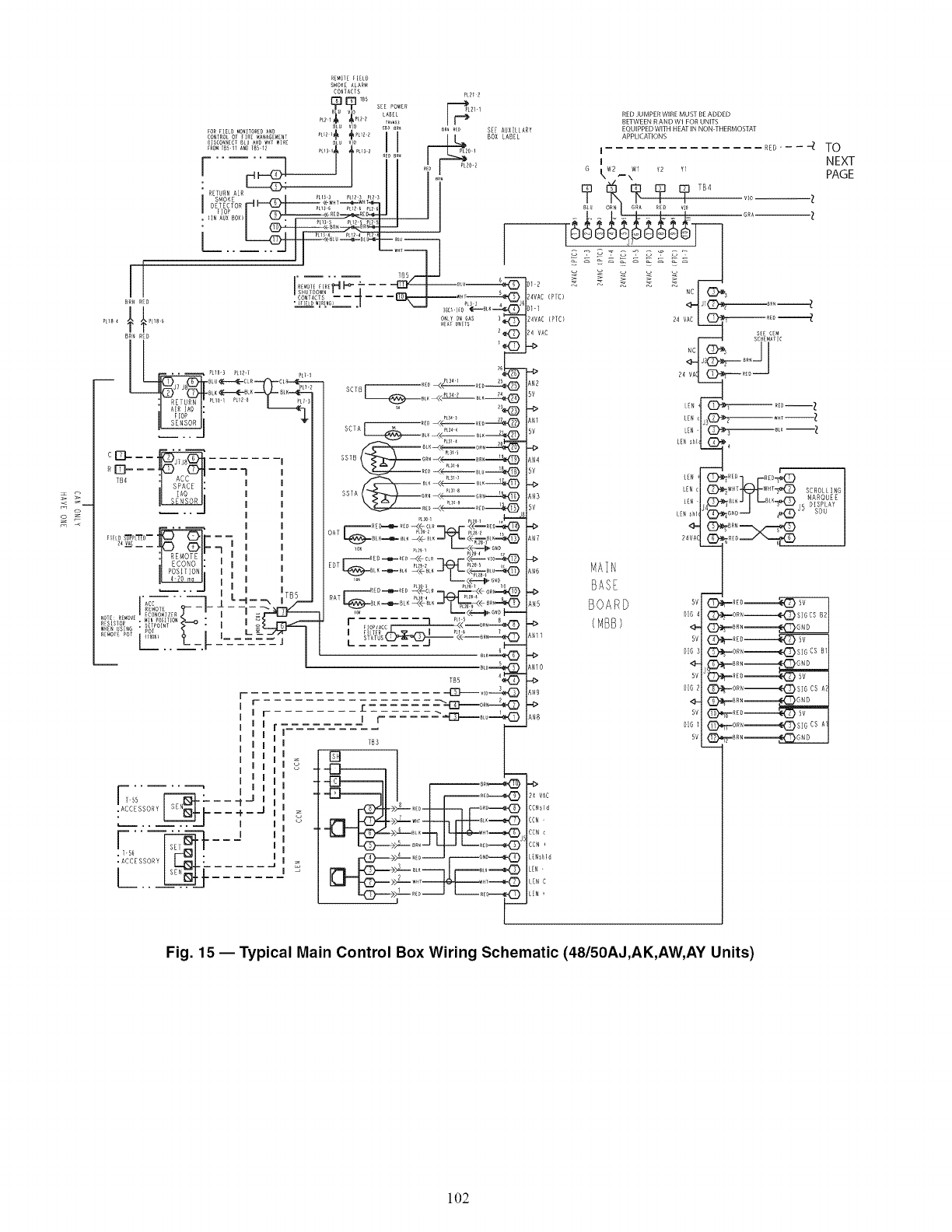
::= r_
<z
_[_OT_ FIELO
S_Oi<_ ALAR_
CONTACTS ?E212
_ V0 LA_L
8_ V_0 _?_ _i__"_"_E,2P__?# °
FORREED MORITOREDAND _ c_ e_. eR_ _E_ SE AB ARY EQUIPPEDWITH HEATIN NON THERMOSTAT
CONTROLOF_IR[_A_AGE_ENT P[12:,_ _PL12Z [ [ I / BOX LABEL APPLICATIONS
..... -Jl ......"m '-
I NEXT
o-I G W2 Wl ?2 Y
_T T R --<÷W_T----.._W_
B_ EC O PU36 9L_20 _L26 BLU ORN GRA R_]) VlO
..... __ _ _;_____
I I I SHU]DOWN S ...... NC I _"_I_S
CONTACTS ..... w_; _4VAC (PIC)
/ / ..... '_ _--°"a<D,-II _'>_
............ HEAl_IT$ 24 VAC sSS_MCA_MC
_---__c_II---7 , __"-_o_--_ _ .,_,E°_ r-_-_
:J RE-MOTEL l I l I _--i--REO--_--_ <<c_m_r-<<--,,o--_ 4>
.... _ J L-- ,/tSb RATI _ P o4 l'_ Ptz_ _
_,E,<,_ .,,!,_ _- . I _LrrF,_ . RO_,ACC.... -- ,_ (M% )
RE_O_R POT _ L =--_/?r lFLIER I _u o
I
I
I
I
I
I
[]ss _L------ I ,
_::_ _J- --I-"
!;-5_ r_ _, J
C7 F......
TB5 4_ "=
I- ,ZZF.-J_o----_
r £ ..... ----'--13]_o_,_
TB3
r_}--_ :>_-_.--J ri-i_.o----_®
INIO
"4>
$N9
4>
_N8
-b
24 VAC
CCNsld
CCN-
CCN<
CCN
L[NsHd
LER -
IEN C
LEN
BOARD (D-'*r.-,o_,------------------_DsIBCSBB
DG _ (Z_;.-ORN-========_Z_SI G CS B
_BRN =========_G ND
<Z>,_-_oR,======_{Z}SIGcs A
Fig. 15 -- Typical Main Control Box Wiring Schematic (48150AJ,AK,AW, AY Units)
102

C_3
WIRING
DIAGRAM
LEI
3!0E
_LARM_ i
/
THE 020 027 UNITS ONLY HAVE 3CONPRESSORS
AND DO HOT USE THE CON B2 CRANKCASE NEAT[RS
TB4
TB4
I_A_SI ×2
CAI C2
) ¢A2 C_
)C BI C2
C_Z C2
OECIC?
0F¢2C?
IFCA¢_
Fig. 15 1Typical Main Control Box Wiring Schematic (48/50AJ,AK,AW, AY Units) (cont)
103
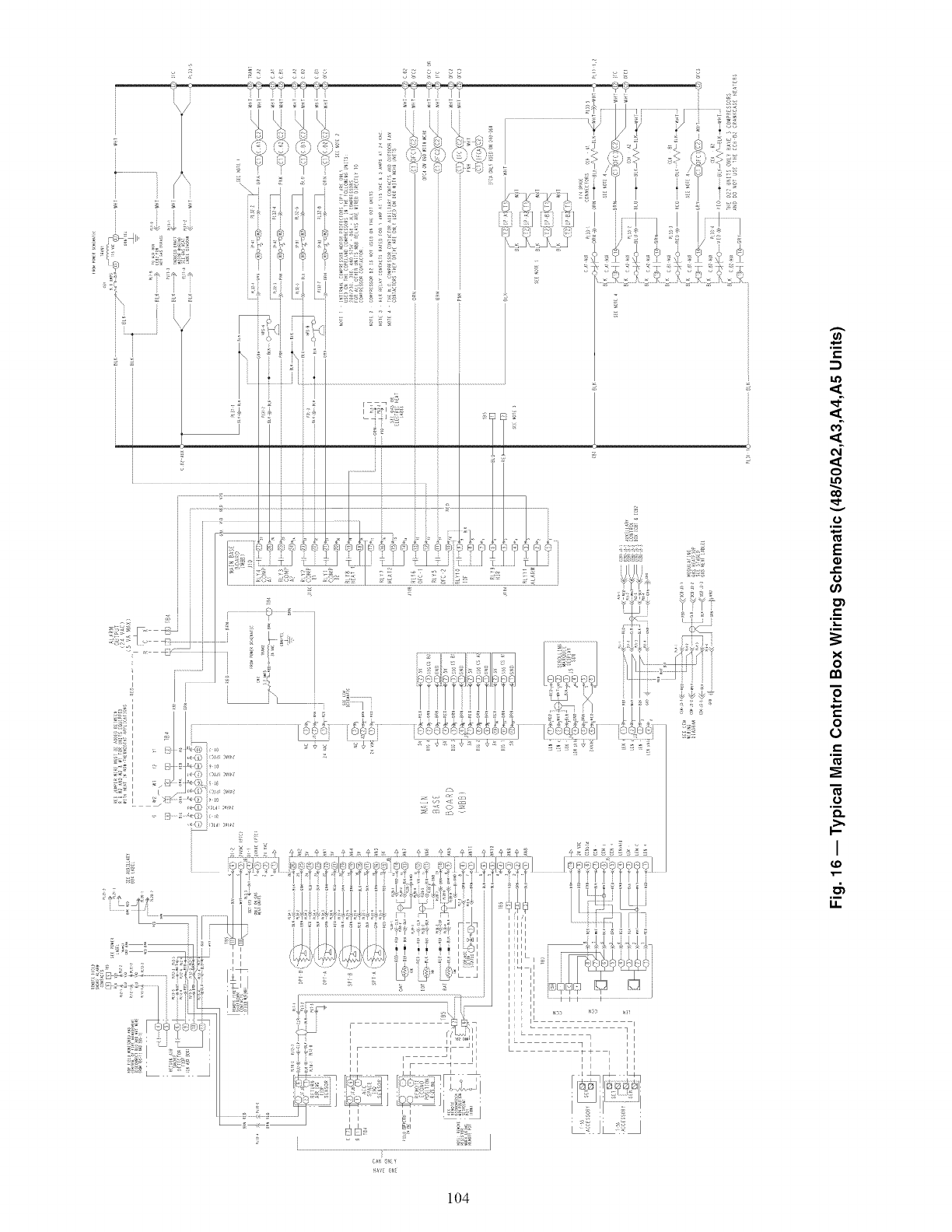
:
3
o
Q
0
.i
E
o
.i
x
o
o
0
m
0
.i
I
_D
.i
I.I.
u/,v: OhF
]£_
104
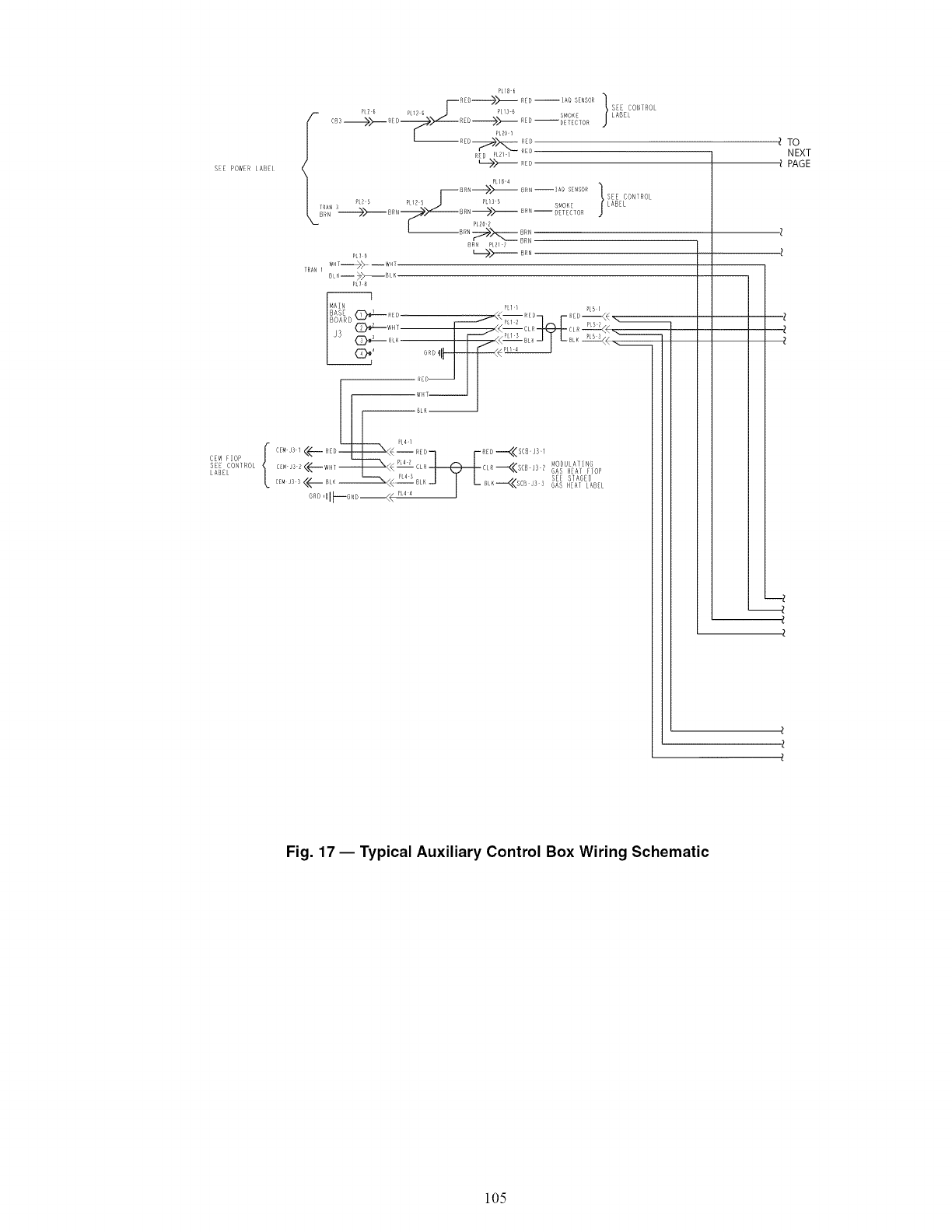
SEE PO!t/IB IABI
PL18 6
I--R _------>>-- _r_--Ao SE,SOR]
PL? 6 RI_ 6 LI3 6 J
' • R S_O E
# C _3 _:----- R I D _-----L_ R_ D ------>>'-- ED -- D....... _;_ECO"] RO
| ............ }
?_g L P 5PL13 5SEE CON ROL
TRAN 3, SMOKE LABEL
1 PL20_
TRAN I WT--_--WHT
PL7 $
I
BOAR D (_--- RED __.........,._< _ R H) q r Ril) --<]< _
/ CD_-r_ I I /_< _J I ,-a,-.:u_.<<.
R£r)_
gL_
CE,tOP { c_...... <<----_ED_<<[_.4 I R_)q F_FD--..<<SC_S1
E;_ J3 2 P 4 2 C MOI)BLAT NG
setCO,_Ro <(--w,_----Ii---_ L__,_--<<SCB J3__ASH(Arlop
GR{) ,[I_----GND--<< PL4 4 [
TO
NEXT
PAGE
Fig. 17- Typical Auxiliary Control Box Wiring Schematic
105
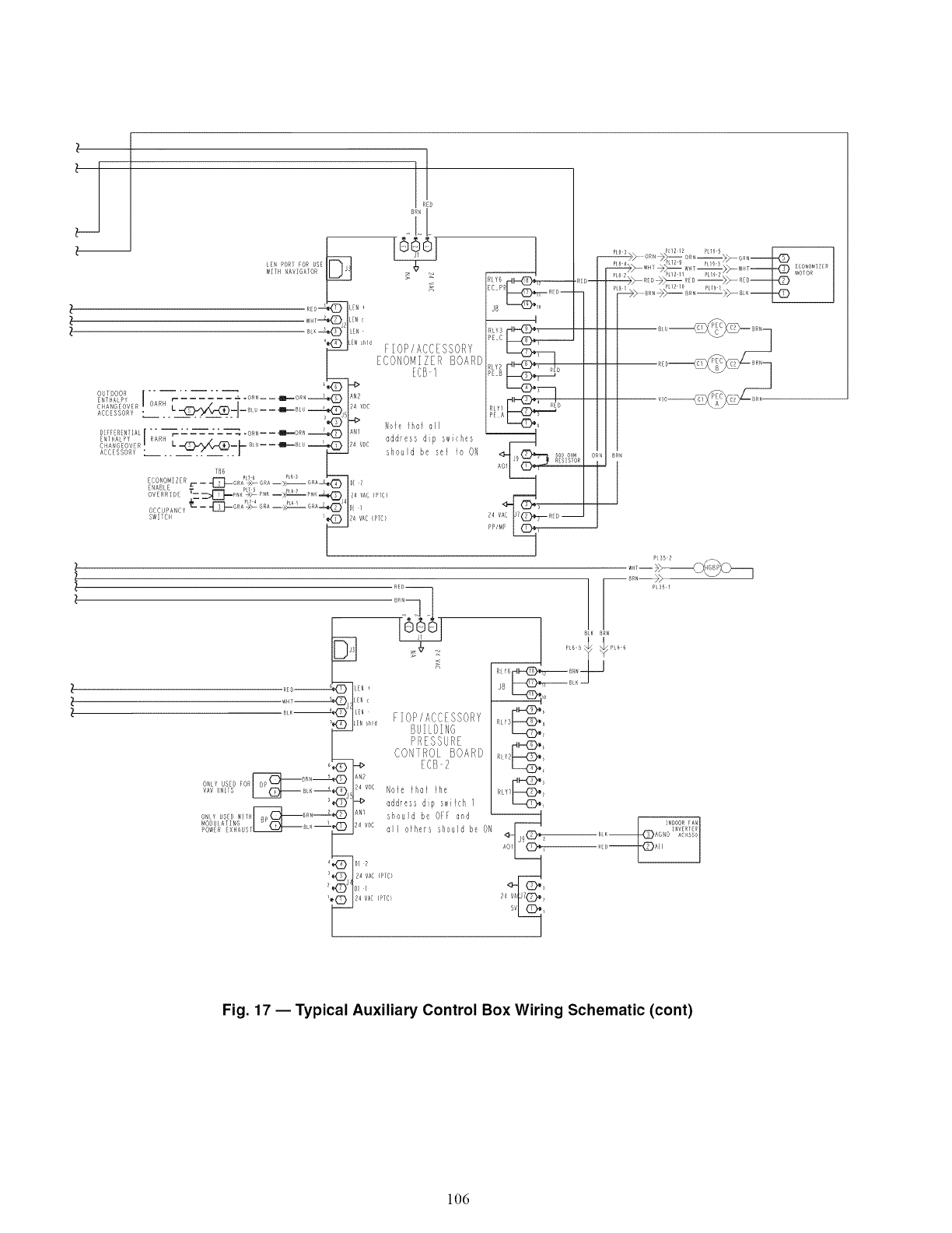
RL'3d_,
PE C
_,_d_, _I 1
P B ED
dHZ>, _)o I
P35 1
RL_2_
s
Fig. 17 -- Typical Auxiliary Control Box Wiring Schematic (cont)
106
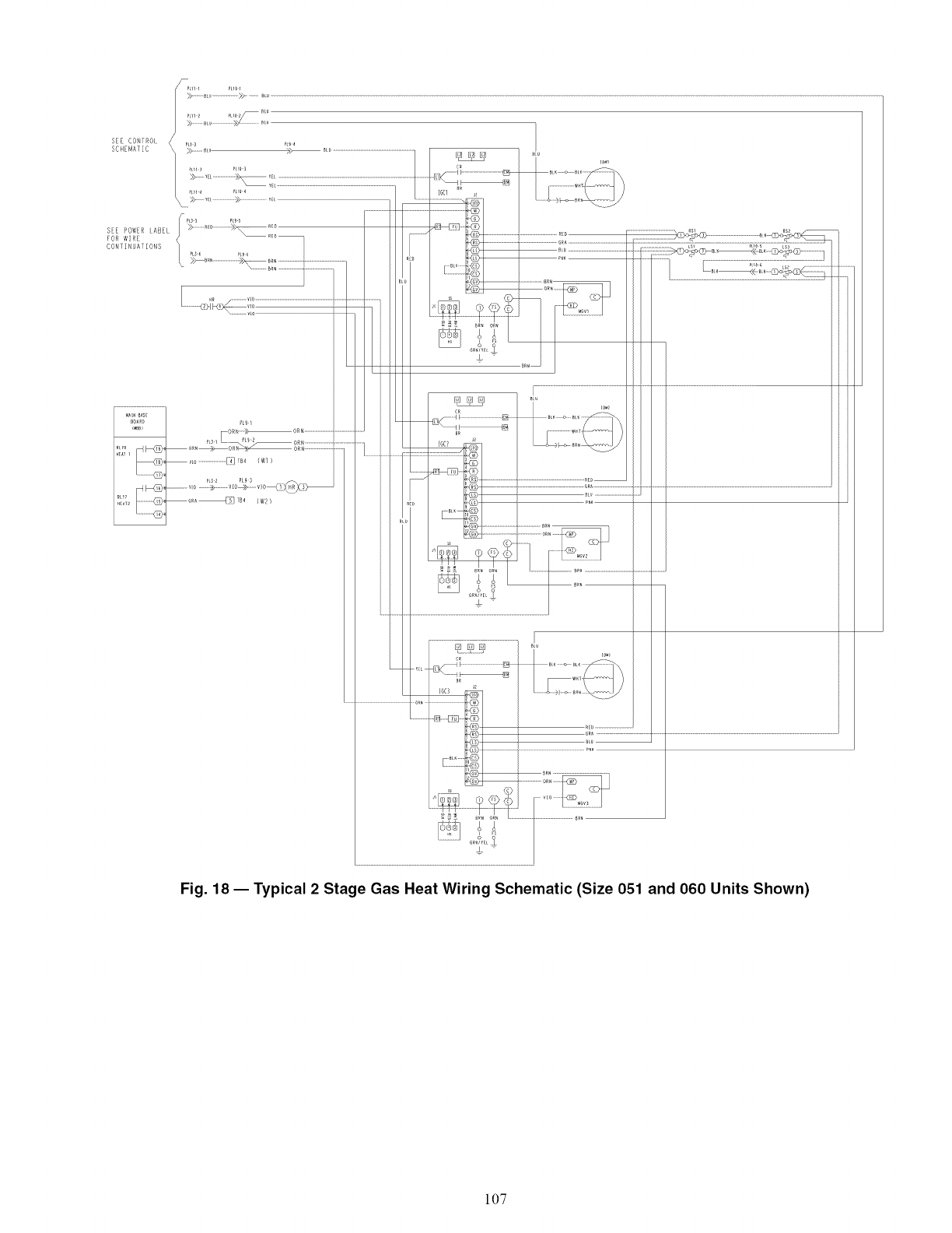
L _, _.... _ L i_ "_ i 1 .......................i .... _ J
....................I......................
C0_1 NU_I ONS ......................................................................................................................... ......................._ ..............................._i,o_ .....................ii_i" ...............................
_ ........................... ............ .... _;,:_;,L_ .....
.......................................................................................................................................t
I *" n_
° ;::
_ _ i".............................................................
/
i
Fig. 18 1 Typical 2 Stage Gas Heat Wiring Schematic (Size 051 and 060 Units Shown)
107
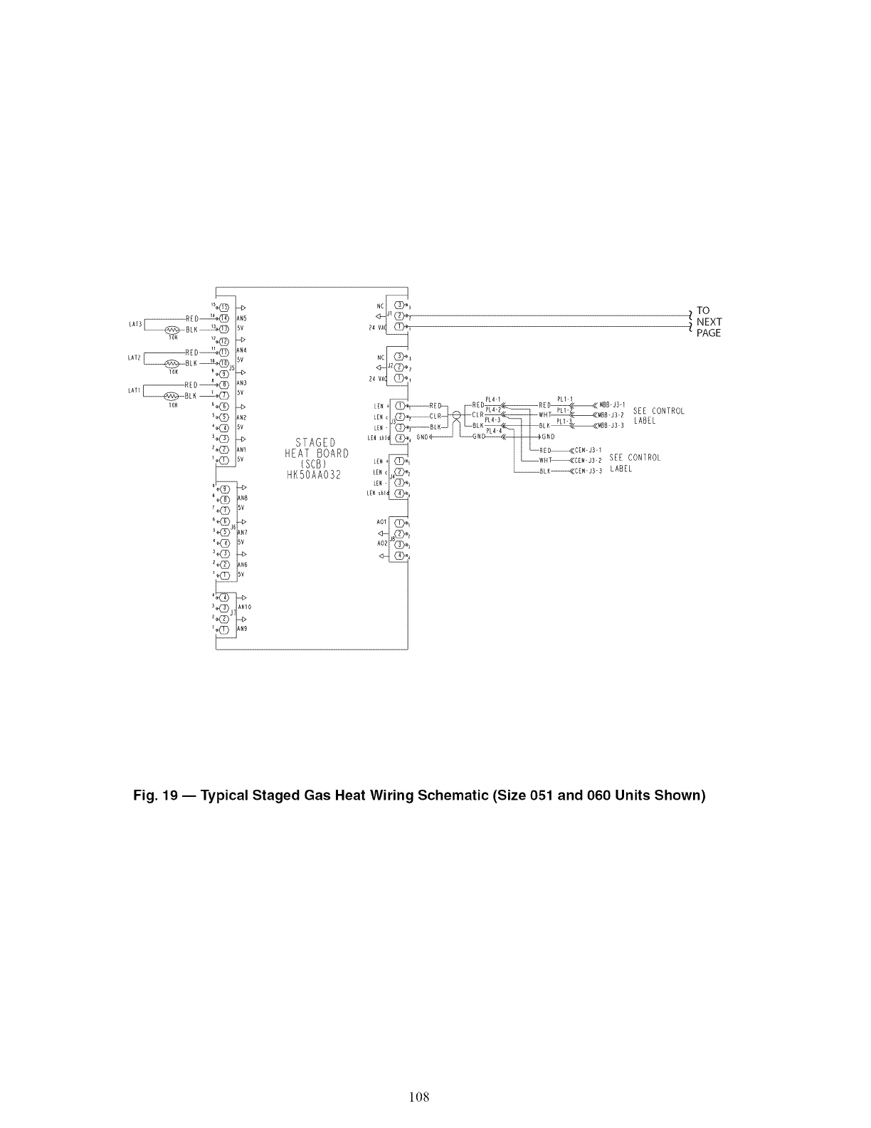
L_o_ BLK _<_J5 <!)
r_RED_
LATI_BLI_ _'K_
IN5
_V
IN4
5V
IN3
5V
_V
STAGED
HEAT BOARD
(SCB)
HKSOAA032
Z TO
NEXT
PAGE
Fig. 19 -- Typical Staged Gas Heat Wiring Schematic (Size 051 and 060 Units Shown)
108
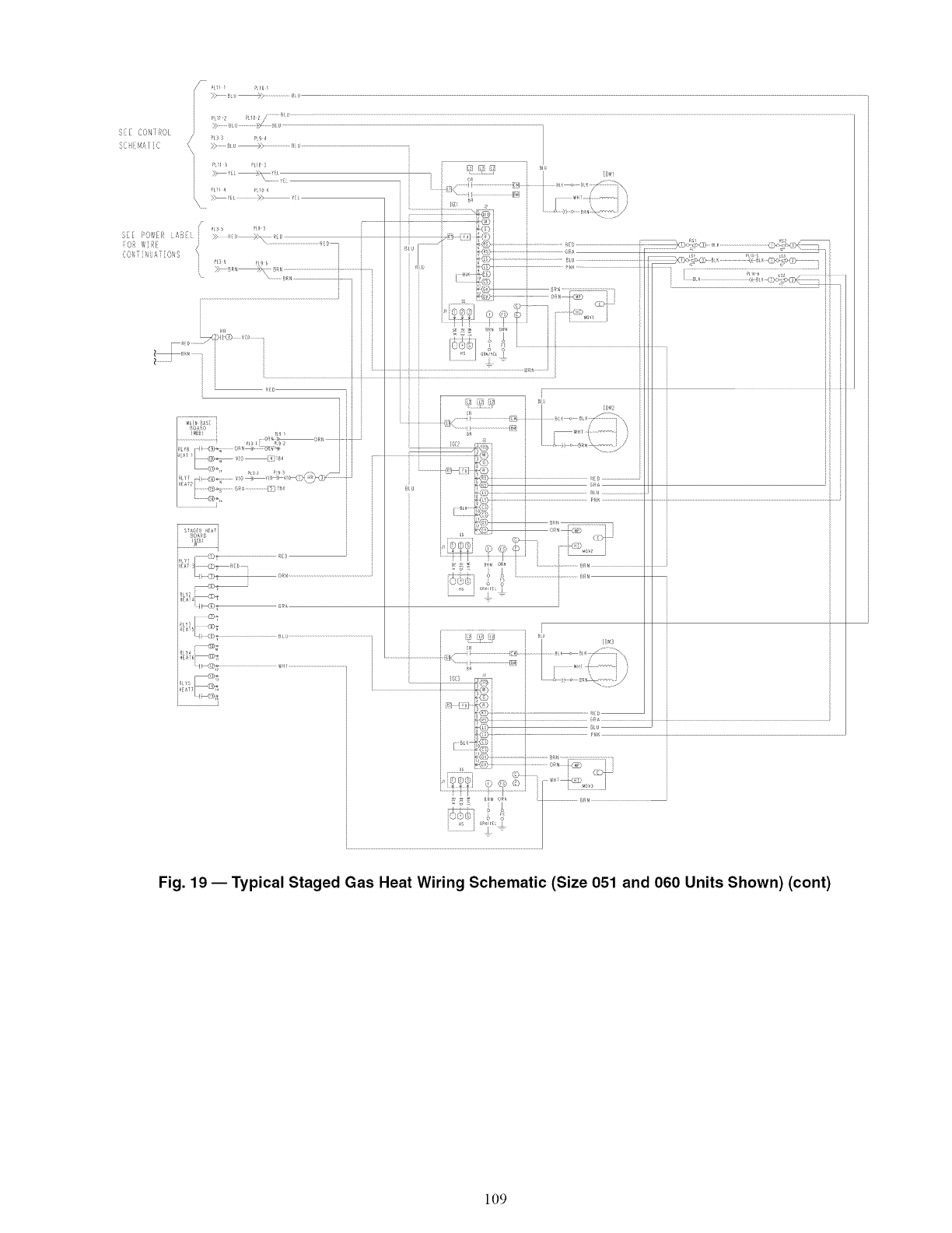
i
Fig. 19 -- Typical Staged Gas Heat Wiring Schematic (Size 051 and 060 Units Shown) (cont)
109
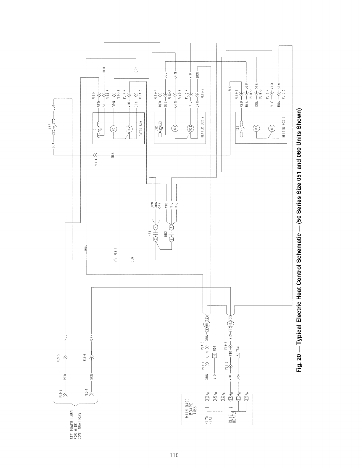
€,,
0
t_
€,,
o
o
"o
€,,
o
N
t_
,_,,,
t_
o
I
o
E
e,,
o
e,,
o
o
,_-
W
o
I--
I
o
110
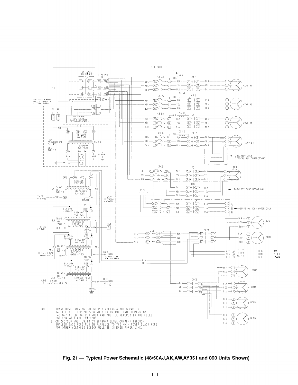
S[ NOTE 2_\\ \
x_" CS M
IfCB F¢ ]FM
_E_................._ /
,u @1 _'
BK_ _BLK_ i'i _208/2SOV 30HP MOTORONLY
__ ...................... ]
I I ,c_
YEL_ _YEL__: _ ........_08/BSOV401> MOORONLY
CaB
....................
©FCI BLU _ _
BLK I (2 BLF_
.... ...... _0+,,,>_7_............................................_Ii_ To
I[,_[_ _ ::::::::::::3 NEXT
_ BLu PAGE
OFM3
©_M4
6Ra/YEL
......1.......
OM5
NOIF: 1 IRANSFORMER WIRING FOR SUPPLY V@IAGES ARE SHOWN IN
TABLE C & D FOR 208/230 VOLT UNITS TIE TRANSFORMERS ARE
fACTORY WIR[D FOR 230 VOlT AND MUST B[ REWIRED IN THE PI[ID
_OR 208 VOLI APPLICA[IONS
2 ON 208/250 VOLT UNITS ¢S SENSORS SENSE CURRENT THROU6H
SMALLER GAGF WIR[ RUN IN PARAUEL TO THE MAIN POWER BLACX WIRE
fOR O]HER VOW]AGES SENSOR WILL BY IN MAIN POWER LISP
O:M6
Fig. 21 -- Typical Power Schematic (48/50AJ,AK,AW, AY051 and 060 Units Shown)
111
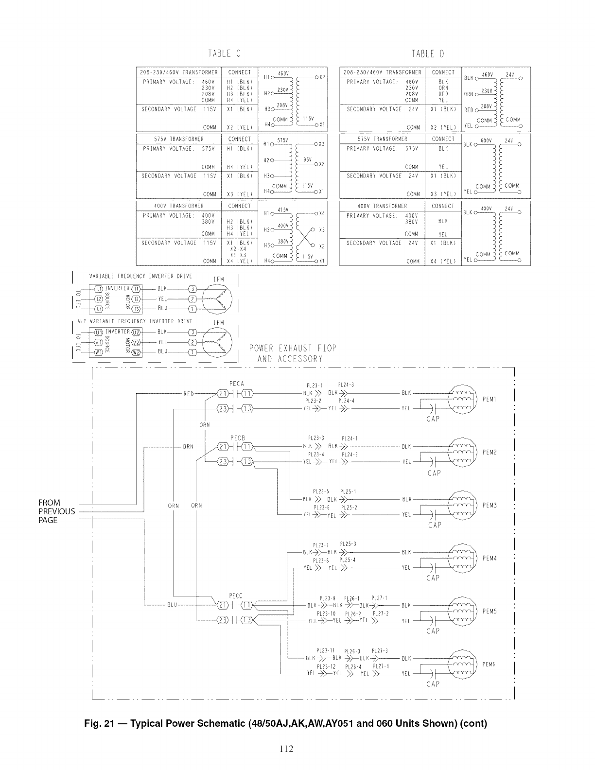
TABLEC
208-230/460V TRANSFORMER I CONNECT
PRIMARY VOLTAGE: 460V HI (8LK)
230V H2 (6LK)
208V H3 (BLK)
COMM H4 (YEL)
SECONDARY VOLTAGE 115V Xl (ELK)
COMM X2 (YEL)
575V IRANSFORMER CONNECT
PRIMARY VOLTAGE: 575V HI (BLK)
COMM H4 (YEL) : 95V°x2
SECONDARY VOLTAGE 115V Xl (BLK) 143o................................._ "
115V
COMM X3 (YEL) --oXl
40OV TRANSFORMER CONNECT
H14G _SV]SV- _X4
PRIMARY VOLTAGE: 4OOV h
38OV H2 (BLK) ,_o,-
H3 (BLK) H2_ X3
COMM N4 (YEL)
SECONDARY VOLTAGE llSV Xl (BLK) N3_ 380v" X2
X2-X4
Xl-X3
COMM X4 (YEL)
VARIABLE FREQUENCYINVERTER DRIVE #FM
]ABLE D
208-230/460V TRANSFORMER CONNECT 460v
PRIMARY VOLTAGE: 460V BLK BLKo_
230V ORN "
208V RED ORN_
COMM YEL
SECONDARY VOLTAGE 24V X1 (8LK) RED_
COMM
COMM X2 (YEL) YELo--
575V TRANSFORMER CONNECT BL_ o 600V
PRIMARY VOLTAGE: 575V BLK
COMM YEI
SECONDARY VOLTAGE 24V XI (BLK)
COMM COMM
COMM X3 (YEI) YELo --o
4O0V TRANSFORMER CONNECI
PRIMARY VOLIAGE: 400V
380V BLK
COMM YEL
SECONDARY VOLIAGE 24V XI (BLK)
COMM X4 (YEL)
COMM COMM
iYELG ...................... o
ALT VARIABLE FREQUENCY INVERTER DRIVE ZFM
POWEREXIIAUSII:::]OP
AND ACCESSORY
FROM
PREVIOUS
PAGE
ORN
--BLU
PECA PL231 PL24 5
RED_ _ 8LK->>-- BL K _> BLK
PL23-2 PL24 4 P M1
YEL_/x YEI )> YEt CAP
ORN
I PECB PL2B3 PL24-
BRN_ _ BLK+_ B K--_> -- BIK .............
PL23 4 PL24-2 P M2
.................................................................................................................
_I PL?3 5 PL25-
_LBLK }>> B K -__ B K
ORN _ P123 6 P 25-2 P M3
YEL_y E _ ......................................................................................................YL
CAP
PL23 7 PL25-3
BL K-->}>-_BLK BLK
P238 PL254
YEL
F YEL@_ YEL-->> CAP
x PECC _ PL239 PL26 1PL2?-I _-
_(_1', BLK_BLK_BLK_y[PL23 I0_Y t _YEL_>P26-2 PL27 2 BLK__}YEL
I / BLK-->/x B K ->_--BLK__iX_B K
PL23-I2 P.26-4 P] 27-4
CAP
PEM4
PEM5
PEM6
Fig. 21 -- Typical Power Schematic (48/5OAJ,AK,AW, AYO51 and 060 Units Shown) (cent)
112
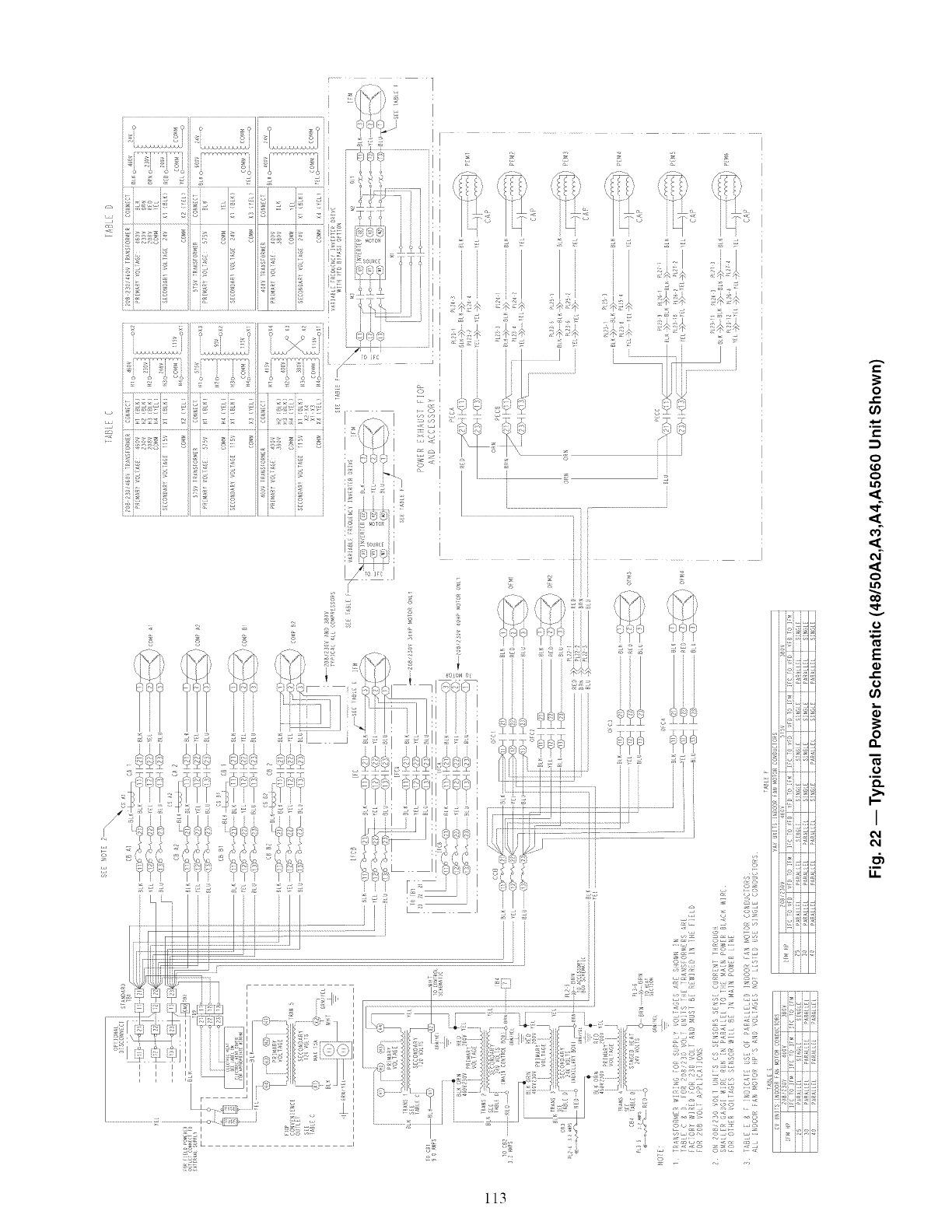
113
'!i!
?
e,,
o
e-
e,,
o
ID
o
o
v
E
e,,
o
I
6_
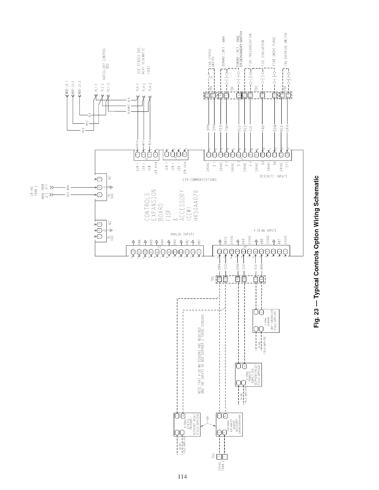
o
S
<
-<?J <]_
R
•+,. • z
s s
J D :-
_-7 --V--- 1 p-r--% _--1 r-J
,_,, _ i_ ,,i ? _ ,,_,
5I .....!.... I ........ II
i,_, 0 i ,o t 0
,........... _'I] 2
O _¢F_[ /Hi Ijr_
I , (}0141.U,I i A / 0 I, S
> cXP
¢/) C_ ct °c\J
........i£> c >
C'q ;x_ UI_ ,'!P <a;;
J
42,3 blA ]f'f'Ij[3
/,!£0' I'\PL I S - _/ i -#
c_ :> cn
_; _......
............ _/
,I
! .
_s
"X_;
o-o
o &- I I
I "_;I
* 400 _
II I :: I I
I _; I I I
114
o
E
o
"E
O
O
m
£
O
o
o
I
€_
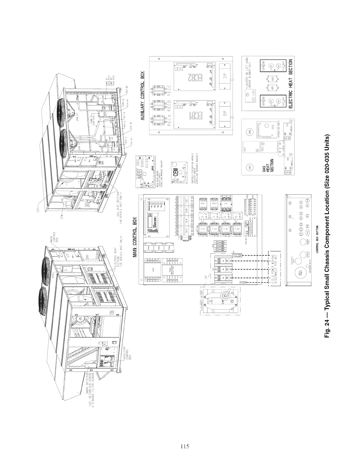
/
i-
o
m
o_
o
N
t_
o
.m
o
o
,.J
c-
O
o
0
c-
O
I
115
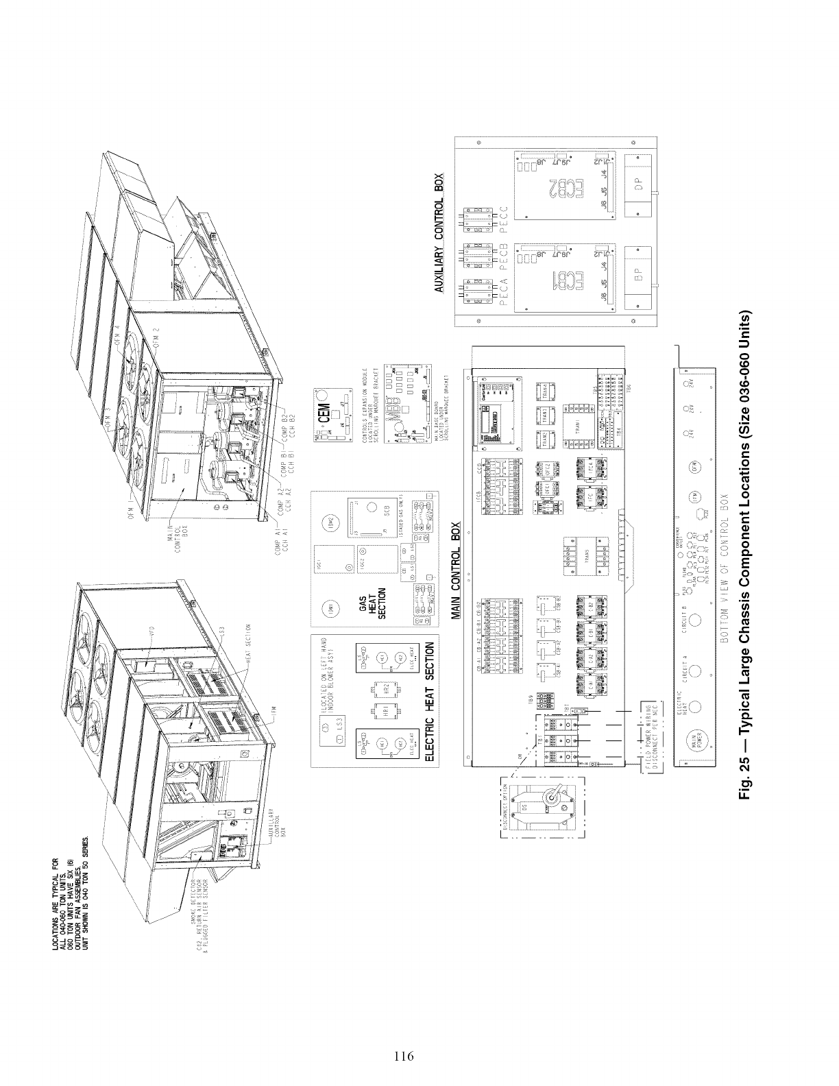
f
LLI
3
L ........ _
o;7 . I
o I
o I
_\ :Y I
[i7 I
_o I
:/\ I
_,:L)1
I
;, d\
ii\ ;I
...................................i
?
ill
N
v
0
o
b.... 0
o
,,_1
._o
I
m
116
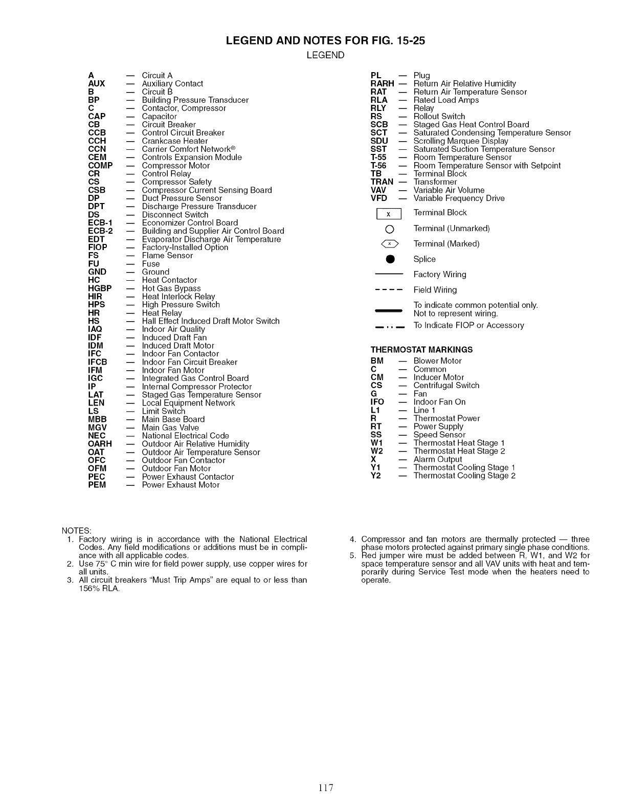
A
AUX
B
BP
C
CAP
CB
CCB
CCH
CCN
CEM
COMP
CR
CS
CSB
DP
DPT
DS
ECB-1
ECB-2
EDT
FlOP
FS
FU
GND
HC
HGBP
HIR
HPS
HR
HS
IAQ
IDF
IDM
IFC
IFCB
IFM
IGC
IP
LAT
LEN
LS
MBB
MGV
NEC
OARH
OAT
OFC
OFM
PEC
PEM
LEGEND AND NOTES FOR FIG. 15-25
LEGEND
-- Circuit A
-- Auxiliary Contact
-- Circuit B
-- Building Pressure Transducer
-- Contactor, Compressor
-- Capacitor
-- Circuit Breaker
-- Control Circuit Breaker
-- Crankcase Heater
-- Carrier Comfort Network ®
-- Controls Expansion Module
-- Compressor Motor
-- Control Relay
-- Compressor Safety
-- Compressor Current Sensing Board
-- Duct Pressure Sensor
-- Discharge Pressure Transducer
-- Disconnect Switch
-- Economizer Control Board
-- Building and Supplier Air Control Board
-- Evaporator Discharge Air Temperature
-- Factory-Installed Option
-- Flame Sensor
-- Fuse
-- Ground
-- Heat Contactor
-- Hot Gas Bypass
-- Heat Interlock Relay
-- High Pressure Switch
-- Heat Relay
-- Hall Effect Induced Draft Motor Switch
-- Indoor Air Quality
-- Induced Draft Fan
-- Induced Draft Motor
-- Indoor Fan Contactor
-- Indoor Fan Circuit Breaker
-- Indoor Fan Motor
-- Integrated Gas Control Board
-- Internal Compressor Protector
-- Staged Gas Temperature Sensor
-- Local Equipment Network
-- Limit Switch
-- Main Base Board
-- Main Gas Valve
-- National Electrical Code
-- Outdoor Air Relative Humidity
-- Outdoor Air Temperature Sensor
-- Outdoor Fan Contactor
-- Outdoor Fan Motor
-- Power Exhaust Contactor
-- Power Exhaust Motor
PL --
RARH --
RAT --
RLA --
RLY --
RS --
SCB --
SCT --
SDU --
SST --
T-55 --
T-56 --
TB
TRAN --
VAV --
VFD --
©
45_
0
Plug
Return Air Relative Humidity
Return Air Temperature Sensor
Rated Load Amps
Relay
Rollout Switch
Staged Gas Heat Control Board
Saturated Condensing Temperature Sensor
Scrolling Marquee Display
Saturated Suction Temperature Sensor
Room Temperature Sensor
Room Temperature Sensor with Setpoint
Terminal Block
Transformer
Variable Air Volume
Variable Frequency Drive
Terminal Block
Terminal (Unmarked)
Terminal (Marked)
Splice
Factory Wiring
Field Wiring
To indicate common potential only.
Not to represent wiring.
To Indicate FlOP or Accessory
THERMOSTAT MARKINGS
BM -- Blower Motor
C -- Common
CM -- Inducer Motor
CS -- Centrifugal Switch
G -- Fan
IFO -- Indoor Fan On
L1 -- Line 1
R -- Thermostat Power
RT -- Power Supply
SS -- Speed Sensor
Wl -- Thermostat Heat Stage 1
W2 -- Thermostat Heat Stage 2
X -- Alarm Output
Y1 -- Thermostat Cooling Stage 1
Y2 -- Thermostat Cooling Stage 2
NOTES:
1. Factory wiring is in accordance with the National Electrical
Codes. Any field modifications or additions must be in compli-
ance with all applicable codes.
2. Use 75 ° C min wire for field power supply, use copper wires for
all units.
3. All circuit breakers "Must Trip Amps" are equal to or less than
156% RLA.
4,
5.
Compressor and fan motors are thermally protected -- three
phase motors protected against primary single phase conditions.
Red jumper wire must be added between R, Wl, and W2 for
space temperature sensor and all VAV units with heat and tem-
porarily during Service Test mode when the heaters need to
operate.
ll7
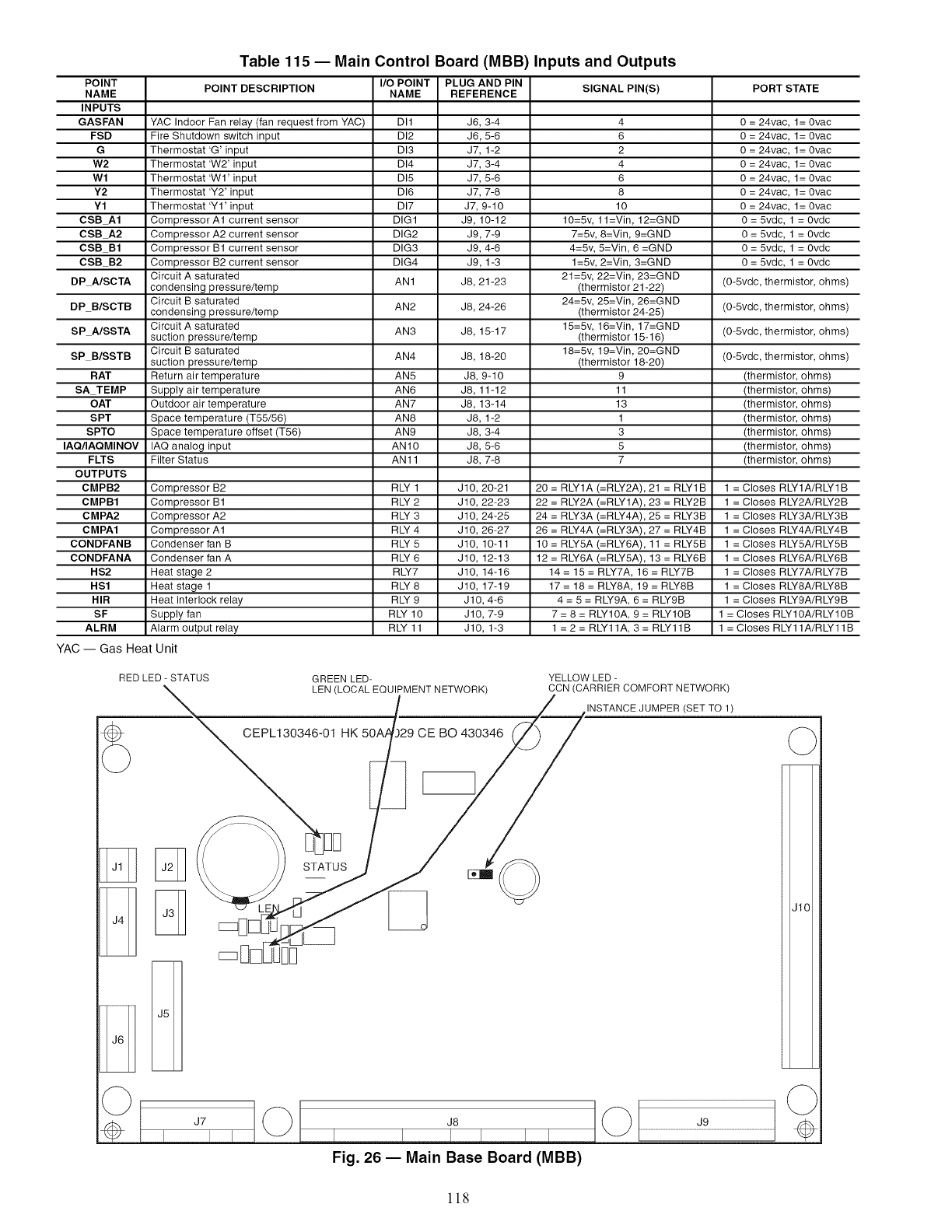
Table 115 -- Main Control Board (MBB) Inputs and Outputs
POINT POINT DESCRIPTION I/O POINT PLUG AND PIN SIGNAL PIN(S) PORT STATE
NAME NAME REFERENCE
INPUTS
GASFAN YAC Indoor Fan relay (fan request from YAC) DI1 36, 3-4 4 0 = 24vac, 1= 0vac
FSD Fire Shutdown switch input DI2 J6, 5-6 6 0 = 24vac, 1= 0vac
G Thermostat 'G' input DI3 J7, 1-2 2 0 = 24vac, 1= 0vac
W2 Thermostat 'W2' input DI4 J7, 3-4 4 0 = 24vac, 1= 0vac
Wl Thermostat 'WI' input DI5 J7, 5-6 6 0 = 24vac, 1= 0vac
Y2 Thermostat 'Y2' input DI6 J7, 7-8 8 0 = 24vac, 1= 0vac
Y1 Thermostat 'YI' input DI7 J7, 9-10 10 0 = 24vac, 1= 0vac
CSBA1 Compressor A1 current sensor DIG1 J9, 10-12 10=5v, 11=Vin, 12=GND 0= 5vdc, 1 =Ovdc
CSBA2 Compressor A2 current sensor DIG2 J9, 7-9 7=5v, 8=Vin, 9=GND 0 = 5vdc, 1 = Ovdc
CSB B1 Compressor B1 current sensor DIG3 J9, 4-6 4=5v, 5=Vin, 6 =GND 0 = 5vdc, 1 = Ovdc
CSB B2 Compressor B2 current sensor DIG4 J9, 1-3 1=5v, 2=Vin, 3=GND 0 = 5vdc, 1 = Ovdc
Circuit A saturated 21=5v, 22=Vin, 23=GND (0-5vdc, thermistor, ohms)
DP NSCTA condensing pressure/temp AN1 J8, 21-23 (thermistor 21-22)
Circuit B saturated 24=5v, 25=Vin, 26=GND
DP B/SCTB condensing pressure/temp AN2 J8, 24-26 (thermistor 24-25) (0-5vdc, thermistor, ohms)
15=5v, 16=Vin, 17=GND
SP NSSTA Circuit A saturated AN3 J8, 15-17 (0-5vdc, thermistor, ohms)
suction pressure/temp (thermistor 15-16)
SP B/SSTB Circuit B saturated 18=5v, 19=Vin, 20=GND (0-5vdc, thermistor, ohms)
suction pressure/temp AN4 J8, 18-20 (thermistor 18-20)
RAT Return air temperature AN5 J8, 9-10 9 (thermistor, ohms)
SA TEMP Supply air temperature AN6 J8, 11-12 11 (thermistor, ohms)
OAT Outdoor air temperature AN7 J8, 13-14 13 (thermistor, ohms)
SPT Space temperature (T55/56) AN8 J8, 1-2 1 (thermistor, ohms)
SPTO Space temperature offset (T56) AN9 J8, 3-4 3 (thermistor, ohms)
IAQ/IAQMINOV IAQ analog input ANIO J8, 5-6 5 (thermistor, ohms)
FLTS Filter Status AN11 J8, 7-8 7 (thermistor, ohms)
OUTPUTS
CMPB2 Compressor B2 RLY 1 J10, 20-21 20 = RLY1A (=RLY2A), 21 = RLY1B 1 = Closes RLY1A/RLY1B
CMPB1 Compressor B1 RLY 2 J10, 22-23 22 = RLY2A (=RLY1A), 23 = RLY2B 1 = Closes RLY2A/RLY2B
CMPA2 Compressor A2 RLY 3 J10, 24-25 24 = RLY3A (=RLY4A), 25 = RLY3B 1 = Closes RLY3A/RLY3B
CMPA1 Compressor A1 RLY 4 J10, 26-27 26 = RLY4A (=RLY3A), 27 = RLY4B 1 = Closes RLY4A/RLY4B
CONDFANB Condenser fan B RLY 5 J10, 10-11 10 = RLY5A (=RLY6A), 11 = RLY5B 1 = Closes RLY5A/RLY5B
CONDFANA Condenser fan A RLY 6 J10, 12-13 12 = RLY6A (=RLY5A), 13 = RLY6B 1 = Closes RLY6A/RLY6B
HS2 Heat stage 2 RLY7 J10, 14-16 14 = 15 = RLY7A, 16 = RLY7B 1 = Closes RLY7A/RLY7B
HS1 Heat stage 1 RLY 8 J10, 17-19 17 = 18 = RLY8A, 19 = RLY8B 1 = Closes RLY8A/RLY8B
HIR Heat interlock relay RLY 9 JlO, 4-6 4 = 5 = RLY9A, 6 = RLY9B 1 = Closes RLY9A/RLY9B
SF Supply fan RLY 10 JlO, 7-9 7 = 8 = RLY10A, 9 = RLY10B 1 = Closes RLYIOA/RLY10B
ALRM Alarm output relay RLY 11 JlO, 1-3 1 = 2 = RLY11A, 3 = RLY11B 1 = Closes RLY11A/RLY11B
YAC -- Gas Heat Unit
YELLOW LED -
CCN (CARRIER COMFORT NETWORK)
Z_INSTANCE JUMPER (SET TO 1)
RED LED - STATUS GREEN LED-
__ _PMENT NETWORK) __
CEPL130346-01 HK 50A4.)29 CE BO 430346 _/
J7
Fig. 26 -- Main Base Board (MBB)
118
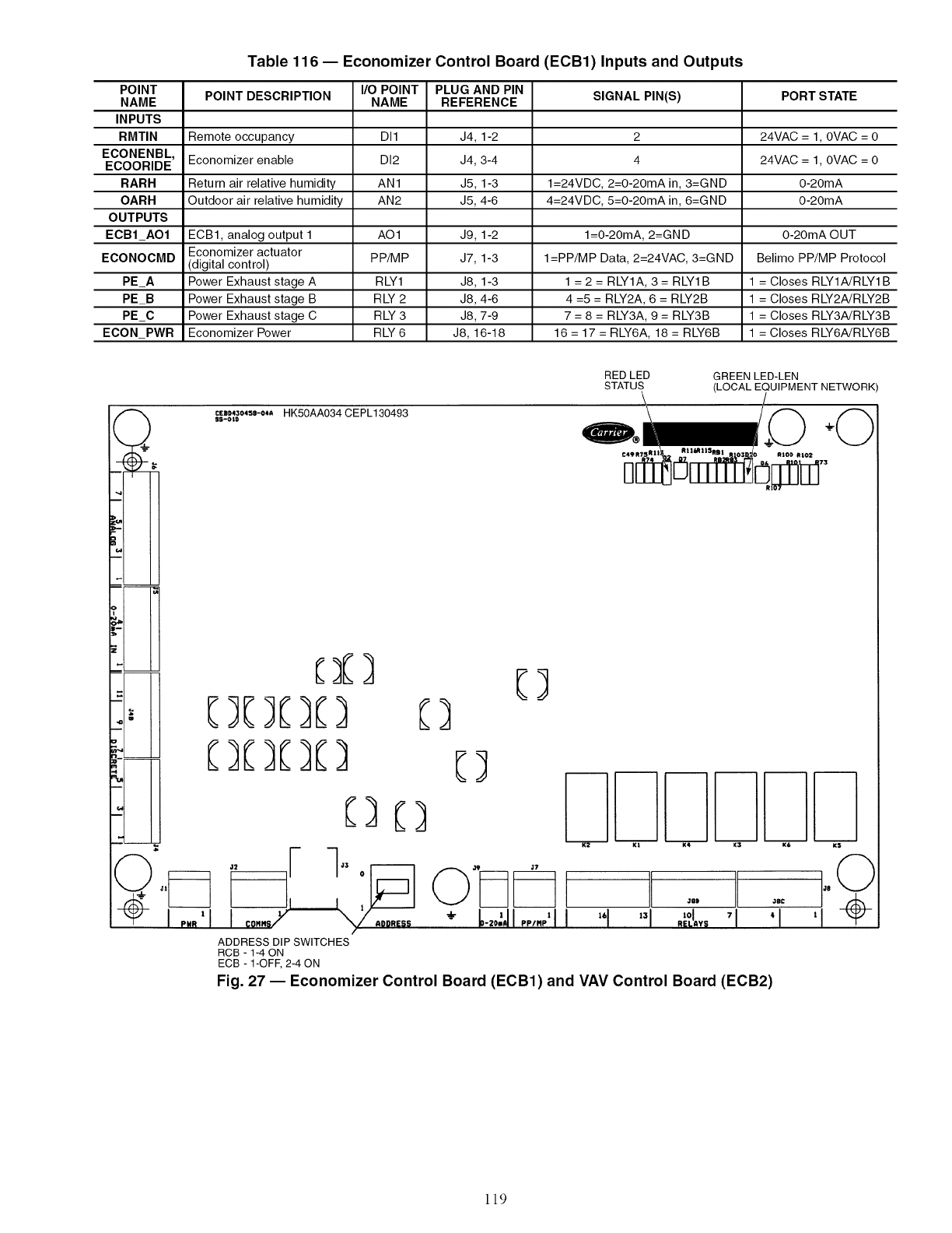
POINT
NAME
INPUTS
RMTIN
ECONENBL,
ECOORIDE
RARH
OARH
OUTPUTS
ECBI_AO1
ECONOCMD
PE_A
PE_B
PE_C
ECON_PWR
Table 116 -- Economizer Control Board (ECB1) Inputs and Outputs
POINT DESCRIPTION
Remote occupancy
Economizer enable
Return air relative humidity
Outdoor air relative humidity
ECB1, analog output 1
Economizer actuator
(digital control)
Power Exhaust stage A
Power Exhaust stage B
Power Exhaust stage C
Economizer Power
I/O POINT
NAME
DI1
DI2
AN1
AN2
AO1
PP/MP
RLY1
RLY2
RLY3
RLY6
PLUG AND PIN
REFERENCE
J4, 1-2
J4, 3-4
J5, 1-3
J5, 4-6
J9, 1-2
J7, 1-3
J8, 1-3
J8, 4-6
J8, 7-9
J8, 16-18
SIGNAL PIN(S)
2
4
1=24VDC, 2=0-20mA in, 3=GND
4=24VDC, 5=0-20mA in, 6=GND
l=0-20mA, 2=GND
I=PP/MP Data, 2=24VAC, 3=GND
1 = 2 = RLY1A, 3 = RLY1B
4 =5 = RLY2A, 6 = RLY2B
7 = 8 = RLY3A, 9 = RLY3B
16 = 17 = RLY6A, 18 = RLY6B
PORT STATE
24VAC =I,0VAC =0
24VAC =I,0VAC =0
0-20mA
0-20mA
0-20mA OUT
Belimo PP/MP Protocol
1 = Closes RLY1A/RLY1B
1 = Closes RLY2A/RLY2B
1 = Closes RLY3A/RLY3B
1 = Closes RLY6A/RLY6B
RED LED GREEN LED-LEN
STATUS (LOCAL EQUIPMENT NETWORK)
cEn43o*sm-o**HK50AA034CEPL130493
SS-OtD
J.
%
[)[) E]
[][)[3[) [3
IC)
O. ,, I--I,,o -,. ,,
Jl
V ' .. ÷ -2°; ,,.g
ADDRESS DIP SWITCHES
RCB -1-4ON
ECB - 1-OFF,2-4 ON
"1 ,,18| ,]8£ €
Fig. 27 -- Economizer Control Board (ECB1) and VAV Control Board (ECB2)
119
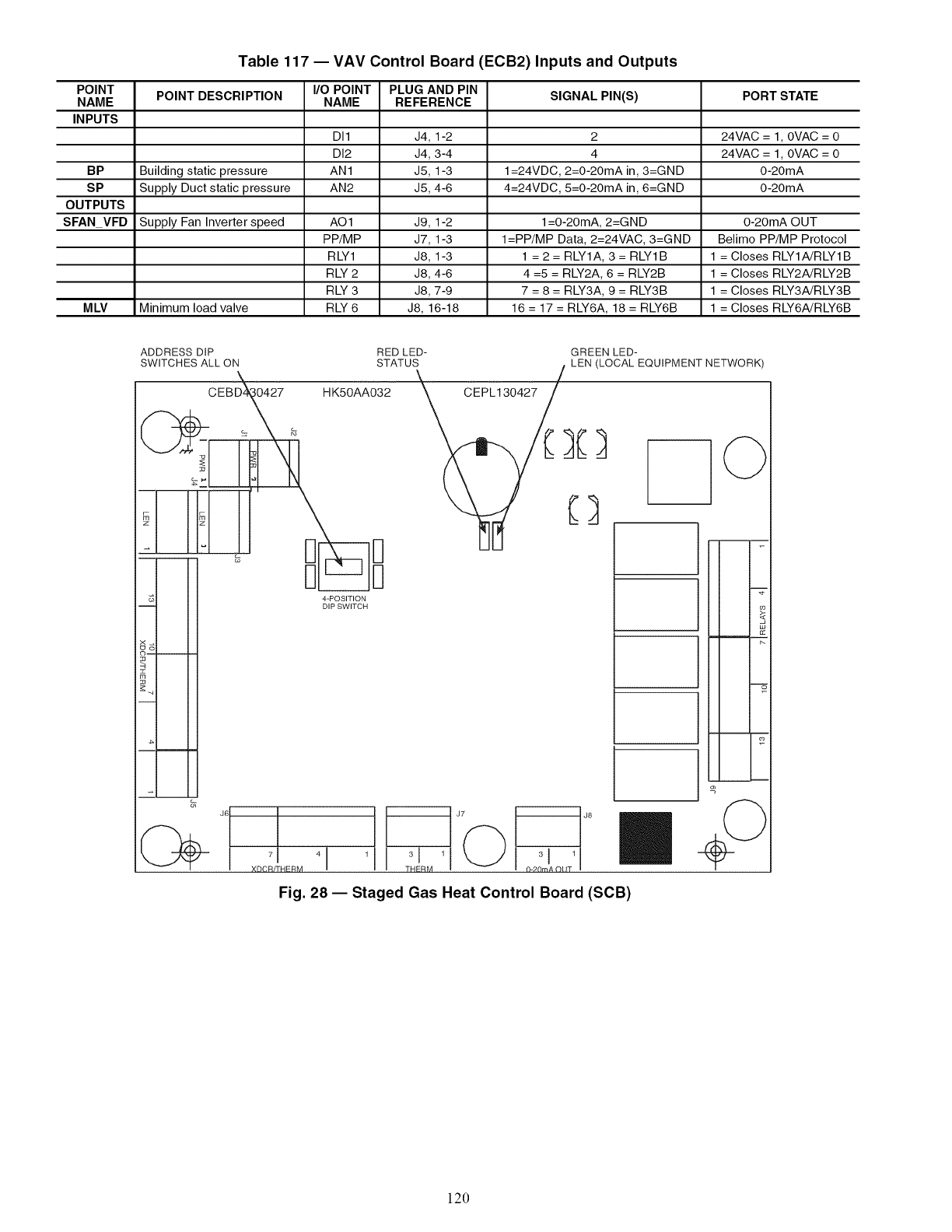
POINT
NAME
INPUTS
BP
SP
OUTPUTS
SFAN_VFD
MLV
Table 117 -- VAV Control Board (ECB2) Inputs and Outputs
POINT DESCRIPTION
Building static pressure
Supply Duct static pressure
Supply Fan Inverter speed
Minimum load valve
I/O POINT
NAME
DI1
DI2
AN1
AN2
AO1
PP/MP
RLY1
RLY2
RLY3
RLY6
PLUG AND PIN
REFERENCE
J4, 1-2
J4, 3-4
J5, 1-3
J5, 4-6
J9, 1-2
J7, 1-3
J8, 1-3
J8, 4-6
J8, 7-9
J8, 16-18
SIGNAL PIN(S)
2
4
1=24VDC, 2=0-20mA in, 3=GND
4=24VDC, 5=0-20mA in, 6=GND
1=0-20mA, 2=GND
I=PP/MP Data, 2=24VAC, 3=GND
1 = 2 = RLY1A, 3 = RLY1B
4 =5 = RLY2A, 6 = RLY2B
7 = 8 = RLY3A, 9 = RLY3B
16 = 17 = RLY6A, 18 = RLY6B
PORT STATE
24VAC =I,0VAC = 0
24VAC =I,0VAC = 0
0-20mA
0-20mA
0-20mA OUT
Belimo PP/MP Protocol
1 = Closes RLY1A/RLY1B
1 = Closes RLY2A/RLY2B
1 = Closes RLY3A/RLY3B
1 = Closes RLY6A/RLY6B
ADDRESS DIP
SWITCHES ALL ON
\
_CEBD_27 HK50AA032
J6 I
7 I 4 1
XDCR/THERM
GREEN LED-
LEN (LOCAL EQUIPMENT NETWORK)
RED LED-
STATUS
Fig. 28 -- Staged Gas Heat Control Board (SOB)
120
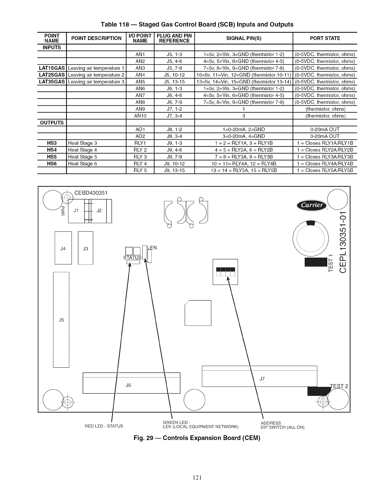
POINT
NAME
INPUTS
LAT1SGAS
LAT2SGAS
LAT3SGAS
OUTPUTS
HS3
HS4
HS5
HS6
Table 118 -- Staged Gas Control Board (SCB) Inputs and Outputs
POINT DESCRIPTION
Leaving air temperature 1
Leaving air temperature 2
Leaving air temperature 3
Heat Stage 3
Heat Stage 4
Heat Stage 5
Heat Stage 6
I/O POINT
NAME
AN1
AN2
AN3
AN4
AN5
AN6
AN7
AN8
AN9
AN10
A01
A02
RLY1
RLY2
RLY3
RLY4
RLY5
PLUG AND PIN
REFERENCE
J5, 1-3
J5, 4-6
J5, 7-9
J5, 10-12
J5, 13-15
J6, 1-3
J6, 4-6
J6, 7-9
J7, 1-2
J7, 3-4
J8, 1-2
J8, 3-4
J9, 1-3
J9, 4-6
J9, 7-9
J9, 10-12
J9, 13-15
SIGNAL PIN(S)
1=5v, 2=Vin, 3=GND (thermistor 1-2)
4=5v, 5=Vin, 6=GND (thermistor 4-5)
7=5v, 8=Vin, 9=GND (thermistor 7-8)
10=5v, 1l=Vin, 12=GND (thermistor 10-11 )
13=5v, 14=Vin, 15=GND (thermistor 13-14)
1=5v, 2=Vin, 3=GND (thermistor 1-2)
4=5v, 5=Vin, 6=GND (thermistor 4-5)
7=5v, 8=Vin, 9=GND (thermistor 7-8)
1
3
1=O-20mA, 2=GND
3=O-20mA, 4=GND
1 =2= RLY1A, 3 = RLY1B
4 = 5 = RLY2A, 6 = RLY2B
7 = 8 = RLY3A, 9 = RLY3B
10 = 11= RLY4A, 12 = RLY4B
13 = 14 = RLY5A, 15 = RLY5B
PORT STATE
(O-5VDC, thermistor, ohms)
(O-5VDC, thermistor, ohms)
(O-5VDC, thermistor, ohms)
(O-5VDC, thermistor, ohms)
(O-5VDC, thermistor, ohms)
(O-5VDC, thermistor, ohms)
(O-5VDC, thermistor, ohms)
(O-5VDC, thermistor, ohms)
(thermistor, ohms)
(thermistor, ohms)
0-20mA OUT
0-20mA OUT
1 = Closes RLY1A/RLY1B
1 = Closes RLY2A/RLY2B
1 = Closes RLY3A/RLY3B
1 = Closes RLY4A/RLY4B
1 = Closes RLY5A/RLY5B
rq[]
STATUS
LEN
J6
RED LED-STATUS GREEN LED-
LEN (LOCAL EQUIPMENT NETWORK)
LIJ
t-
J7
\
ADDRESS
DIP SWITCH (ALL ON)
Fig. 29 -- Controls Expansion Board (CEM)
.€..==
O!
o
.€..==
#_
U
121
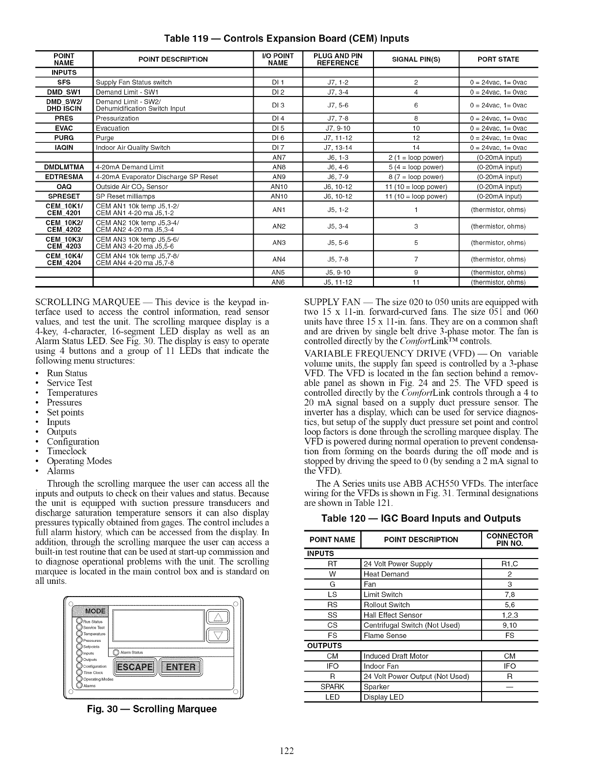
Table 119 -- Controls Expansion Board (CEM) Inputs
POINT I/O POINT PLUG AND PIN
POINT DESCRIPTION SIGNAL PIN(S) PORT STATE
NAME NAME REFERENCE
INPUTS
SFS Supply Fan Status switch DI 1 37, 1-2 2 0 = 24vac, 1= 0vac
DMD SWl Demand Limit - SWl DI 2 J7, 3-4 4 0 = 24vac, 1= 0vac
DMD SW2/ Demand Limit - SW2/
DHD]SClN Dehumidification Switch Input DI 3 J7, 5-6 6 0 = 24vac, 1= 0vac
PRES Pressurization DI 4 J7, 7-8 8 0 = 24vac, 1= 0vac
EVAC Evacuation DI 5 J7, 9-10 10 0 = 24vac, 1= 0vac
PURG Purge DI 6 J7, 11-12 12 0 = 24vac, 1= 0vac
IAQIN Indoor Air Quality Switch DI 7 J7, 13-14 14 0 = 24vac, 1= 0vac
AN7 J6, 1-3 2 (1 = loop power) (O-20mA input)
DMDLMTMA 4-20mA Demand Limit AN8 J6, 4-6 5 (4 = loop power) (O-20mA input)
EDTRESMA 4-20mA Evaporator Discharge SP Reset AN9 J6, 7-9 8 (7 = loop power) (O-20mA input)
OAQ Outside Air CO2 Sensor AN10 J6, 10-12 11 (10 = loop power) (O-20mA input)
SPRESET SP Reset milliamps AN10 J6, 10-12 11 (10 = loop power) (O-20mA input)
CEM 10K1/ CEMAN1 lOktemp J5,1-2/
CEM 4201 CEM AN1 4-20 ma J5,1-2 AN1 J5, 1-2 1 (thermistor, ohms)
CEM 10K2/ CEM AN2 1Ok temp J5,3-4/
CEM 4202 CEM AN2 4-20 ma J5,3-4 AN2 J5, 3-4 3 (thermistor, ohms)
CEM 10K3/ CEM AN3 1Ok temp J5,5-6/ AN3 J5, 5-6 5 (thermistor, ohms)
CEM 4203 CEM AN3 4-20 ma J5,5-6
CEM 10K4/ CEM AN4 1Ok temp J5,7-8/ AN4 J5, 7-8 7 (thermistor, ohms)
CEM 4204 CEM AN4 4-20 ma J5,7-8
AN5 J5, 9-10 9 (thermistor, ohms)
AN6 J5, 11-12 11 (thermistor, ohms)
SCROLLING MARQUEE- This device is the keypad in-
terface used to access the control information, read sensor
values, and test the unit. The scrolling marquee display is a
4-key, 4-character, 16-segment LED display as well as an
Alarm Stares LED. See Fig. 30. The display is easy to operate
using 4 buttons and a group of 11 LEDs that indicate the
following menu structures:
• Run Status
• Service Test
• Temperatures
• Pressures
• Set points
• Inputs
•Outputs
• Configuration
• Timeclock
• Operating Modes
• Alarms
Through the scrolling marquee the user can access all the
inputs and outputs to check on their values and status. Because
the unit is equipped with suction pressure transducers and
discharge saturation temperature sensors it can also display
pressures typically obtained from gages. The control includes a
full alarm history, which can be accessed from the display. In
addition, through the scrolling marquee the user can access a
built-in test routine that can be used at start-up colmnission and
to diagnose operational problems with the unit. The scrolling
marquee is located in the main control box and is standard on
all units.
O Run Status
O Configuration
qime Clock
@AEarm Status
@Operath_gModes
@/Uarms
]
Fig. 30- Scrolling Marquee
SUPPLY FAN -- The size 020 to 050 units are equipped with
two 15 x ll-in, forward-curved fans. The size 051 and 060
units have three 15 x 11-in. fans. They are on a colranon shaft
and are driven by single belt drive 3-phase motor. The fan is
controlled directly by the (_n_folTLink TM controls.
VARIABLE FREQUENCY DRIVE (VFD) -- On variable
volume units, the supply fan speed is controlled by a 3-phase
VFD. The VFD is located in the fan section behind a remov-
able panel as shown in Fig. 24 and 25. The VFD speed is
controlled directly by the (_,fortLink controls through a 4 to
20 mA signal based on a supply duct pressure sensor. The
inverter has a display, which can be used for service diagnos-
tics, but setup of the supply duct pressure set point and control
loop factors is done through the scrolling marquee display. The
VFD is powered during normal operation to prevent condensa-
tion from forming on the boards during the off mode and is
stopped by driving the speed to 0 (by sending a 2 mA signal to
the VFD).
The A Series units use ABB ACH550 VFDs. The interface
wiring for the VFDs is shown in Fig. 31. Terminal designations
are shown in Table 121.
Table 120 -- IGC Board Inputs and Outputs
]CONNECTOR
POINT NAME POINT DESCRIPTION PIN NO.
INPUTS
RT 24 Volt Power Supply R1 ,C
W Heat Demand 2
G Fan 3
LS Limit Switch 7,8
RS Rollout Switch 5,6
SS Hall Effect Sensor 1,2,3
CS Centrifugal Switch (Not Used) 9,10
FS Flame Sense FS
OUTPUTS
CM Induced Draft Motor CM
IFO Indoor Fan IFO
R 24 Volt Power Output (Not Used) R
SPARK Sparker
LED D sp ay LED
122
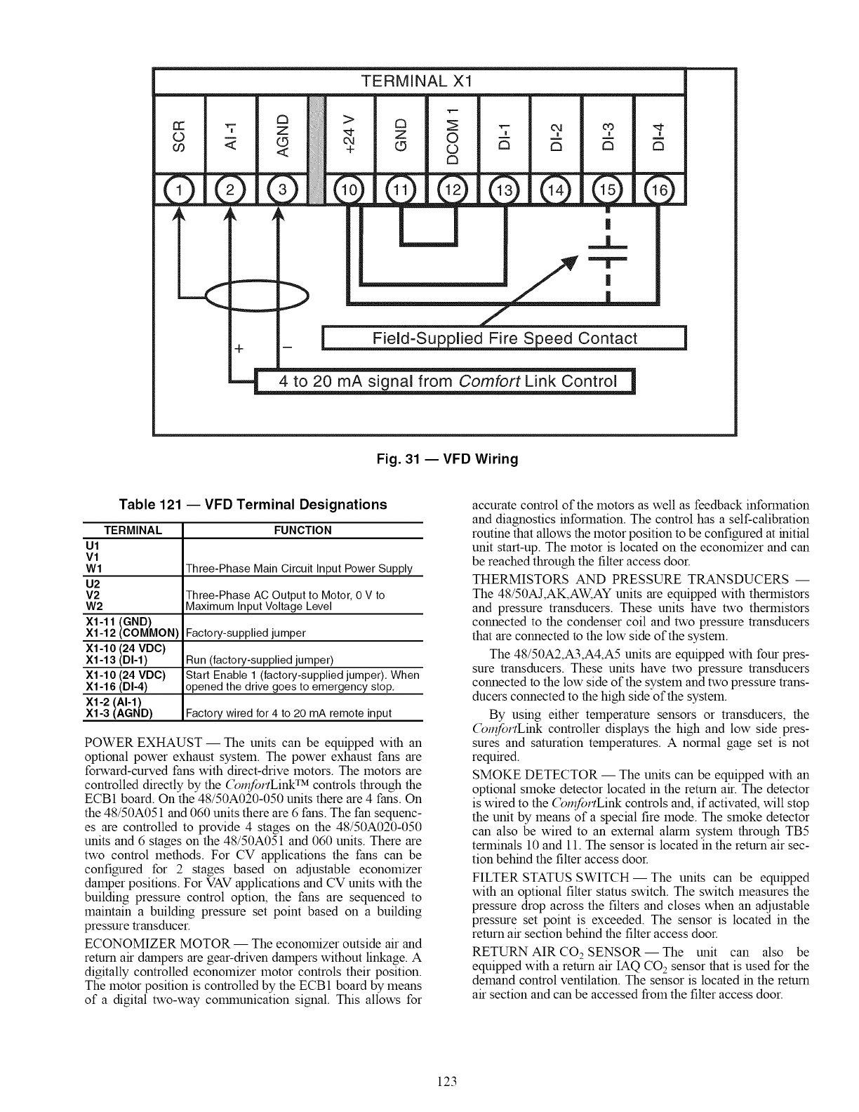
©
co
TYZ -
TERMINAL Xl
",t--
c_ _ T 04 m "I,
O £3 tm D C3
[]
|
__<:::--->
Jr m
_nal from Comfort Link Control
Fig. 31 -- VFD Wiring
Table 121 -- VFD Terminal Designations
TERMINAL FUNCTION
Ul
V1
W1 Three-Phase Main Circuit Input Power Supply
U2
V2 Three-Phase AC Output to Motor, 0 V to
W2 Maximum Input Voltage Level
X1-11 (GND)
X1-12 (COMMON) Factory-supplied jumper
X1-10 (24 VDC)
X1-13 (DI-1) Run (factory-supplied jumper)
X1-10 (24 VDC) Start Enable 1 (factory-supplied jumper). When
X1-16 (DI-4) opened the drive goes to emergency stop,
X1-2 (AI-1)
X1-3 (AGND) Factory wired for 4 to 20 mA remote input
POWER EXHAUST- The units can be equipped with an
optional power exhaust system. The power exhaust fans are
forward-curved fans with direct-drive motors. The motors are
controlled directly by the (_l_fortLink TM controls through the
ECB1 board. On the 48/50A020-050 units there are 4 fans. On
the 48/50A051 and 060 units there are 6 fans. The fan sequenc-
es are controlled to provide 4 stages on the 48/50A020-050
units and 6 stages on the 48/50A051 and 060 units. There are
two control methods. For CV applications the fans can be
configured for 2 stages based on adjustable economizer
damper positions. For VAV applications and CV units with the
building pressure control option, the fans are sequenced to
maintain a building pressure set point based on a building
pressure transducer.
ECONOMIZER MOTOR -- The economizer outside air and
return air dampers are gear-driven dampers without linkage. A
digitally controlled economizer motor controls their position.
The motor position is controlled by the ECB1 board by means
of a digital two-way colr_nunication signal. This allows for
accurate control of the motors as well as feedback information
and diagnostics information. The control has a self-calibration
routine that allows the motor position to be configured at initial
unit start-up. The motor is located on the economizer and can
be reached through the filter access door.
THERMISTORS AND PRESSURE TRANSDUCERS --
The 48/50AJ,AK,AW, AY units are equipped with thermistors
and pressure transducers. These units have two thermistors
connected to the condenser coil and two pressure transducers
that are connected to the low side of the system.
The 48/50A2,A3,A4,A5 units are equipped with four pres-
sure transducers. These units have two pressure transducers
connected to the low side of the system and two pressure trans-
ducers connected to the high side of the system.
By using either temperature sensors or transducers, the
(_mfortLink controller displays the high and low side pres-
sures and saturation temperatures. A normal gage set is not
required.
SMOKE DETECTOR -- The units can be equipped with an
optional smoke detector located in the return air. The detector
is wired to the (_mfortLink controls and, if activated, will stop
the unit by means of a special fire mode. The smoke detector
can also be wired to an external alarm system through TB5
terminals 10 and 11. The sensor is located in the return air sec-
tion behind the filter access door.
FILTER STATUS SWITCH- The units can be equipped
with an optional filter status switch. The switch measures the
pressure drop across the filters and closes when an adjustable
pressure set point is exceeded. The sensor is located in the
return air section behind the filter access door.
RETURN AIR CO 2 SENSOR -- The unit can also be
equipped with a return air IAQ CO2 sensor that is used for the
demand control ventilation. The sensor is located in the return
air section and can be accessed from the filter access door.
123
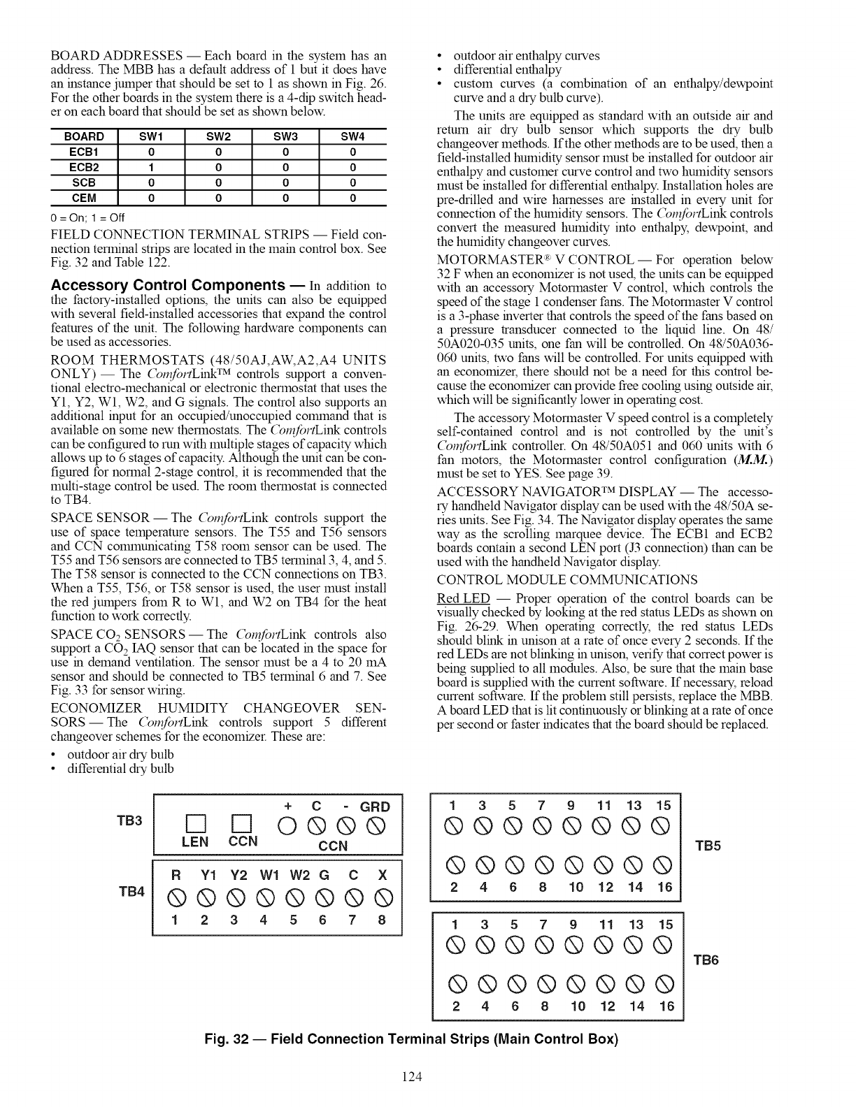
BOARDADDRESSES-- Eachboardinthesystemhasan
address.TheMBBhasadefaultaddressof1butit doeshave
aninstancejumperthatshouldbesetto1asshowninFig.26.
Fortheotherboardsinthesystemthereisa4-dipswitchhead-
eroneachboardthatshouldbesetasshownbelow.
BOARD SW1 SW2 SW3 SW4
ECB1 0 0 0 0
ECB2 1 0 0 0
SCB 0 0 0 0
CEM 0 0 0 0
0 = On; 1 = Off
FIELD CONNECTION TERMINAL STRIPS -- Field con-
nection terminal strips are located in the main control box. See
Fig. 32 and Table 122.
Accessory Control Components EIn addition to
the factory-installed options, the units can also be equipped
with several field-installed accessories that expand the control
features of the unit. The following hardware components can
be used as accessories.
ROOM THERMOSTATS (48/50AJ,AW, A2,A4 UNITS
ONLY)- The (_mfortLink TM controls support a conven-
tional electro-mechanical or electronic thermostat that uses the
Y1, Y2, Wl, W2, and G signals. The control also supports an
additional input for an occupied/unoccupied command that is
available on some new thermostats. The (_mfortLink controls
can be configured to run with multiple stages of capacity which
allows up to 6 stages of capacity. Although the unit can be con-
figured for normal 2-stage control, it is recommended that the
multi-stage control be used. The room thermostat is connected
to TB4.
SPACE SENSOR- The (_mfortLink controls support the
use of space temperature sensors. The T55 and T56 sensors
and CCN communicating T58 room sensor can be used. The
T55 and T56 sensors are connected to TB5 terminal 3, 4, and 5.
The T58 sensor is connected to the CCN connections on TB3.
When a T55, T56, or T58 sensor is used, the user must install
the red jumpers from R to Wl, and W2 on TB4 for the heat
function to work correctly.
SPACE CO2 SENSORS -- The (_mfortLink controls also
support a CO 2 IAQ sensor that can be located in the space for
use in demand ventilation. The sensor must be a 4 to 20 mA
sensor and should be connected to TB5 terminal 6 and 7. See
Fig. 33 for sensor wiring.
ECONOMIZER HUMIDITY CHANGEOVER SEN-
SORS--The (_mfortLink controls support 5 different
changeover schemes for the economizer. These are:
• outdoor air dry bulb
• differential dry bulb
• outdoor air enthalpy curves
• differential enthalpy
• custom curves (a combination of an enthalpy/dewpoint
curve and a dry bulb curve).
The units are equipped as standard with an outside air and
return air dry bulb sensor which supports the dry bulb
changeover methods. If the other methods are to be used, then a
field-installed humidity sensor must be installed for outdoor air
enthalpy and customer curve control and two humidity sensors
must be installed for differential enthalpy. Installation holes are
pre-drilled and wire harnesses are installed in every unit for
connection of the humidity sensors. The (_mfortLink controls
convert the measured humidity into enthalpy, dewpoint, and
the humidity changeover curves.
MOTORMASTER R:V CONTROL -- For operation below
32 F when an economizer is not used, the units can be equipped
with an accessory Motormaster V control, which controls the
speed of the stage 1 condenser fans. The Motormaster V control
is a 3-phase inverter that controls the speed of the fans based on
a pressure transducer connected to the liquid line. On 48/
50A020-035 units, one fan will be controlled. On 48/50A036-
060 units, two fans will be controlled. For units equipped with
an economizer, there should not be a need for this control be-
cause the economizer can provide free cooling using outside air,
which will be significantly lower in operating cost.
The accessory Motormaster V speed control is a completely
self-contained control and is not controlled by the unit's
(_mfortLink controller. On 48/50A051 and 060 units with 6
fan motors, the Motormaster control configuration (M..M..)
must be set to YES. See page 39.
ACCESSORY NAVIGATOR TM DISPLAY -- The accesso-
ry handheld Navigator display can be used with the 48/50A se-
ries units. See Fig. 34. The Navigator display operates the same
way as the scrolling marquee device. The ECB1 and ECB2
boards contain a second LEN port (J3 connection) than can be
used with the handheld Navigator display.
CONTROL MODULE COMMUNICATIONS
Red LED -- Proper operation of the control boards can be
visually checked by looking at the red status LEDs as shown on
Fig. 26-29. When operating correctly, the red stares LEDs
should blink in unison at a rate of once every 2 seconds. If the
red LEDs are not blinking in unison, verify that correct power is
being supplied to all modules. Also, be sure that the main base
board is supplied with the current software. If necessary, reload
current software. If the problem still persists, replace the MBB.
A board LED that is lit continuously or blinking at a rate of once
per second or faster indicates that the board should be replaced.
TB3
TB4
+ C GRD
F1 F1 Q@@@
LEN CCN CCN
R Y1 Y2 W1 W2 G C X
@@@@@@@@
12345678
135 7 9 11 13 15
@@@@@@@@
@@@@@@@@
2 4 6 8 10 12 14 16
135 7 9 11 13 15
@@@@@@@@
@@@@@@@@
2 4 6 8 10 12 14 16
Fig. 32 -- Field Connection Terminal Strips (Main Control Box)
TB5
TB6
124
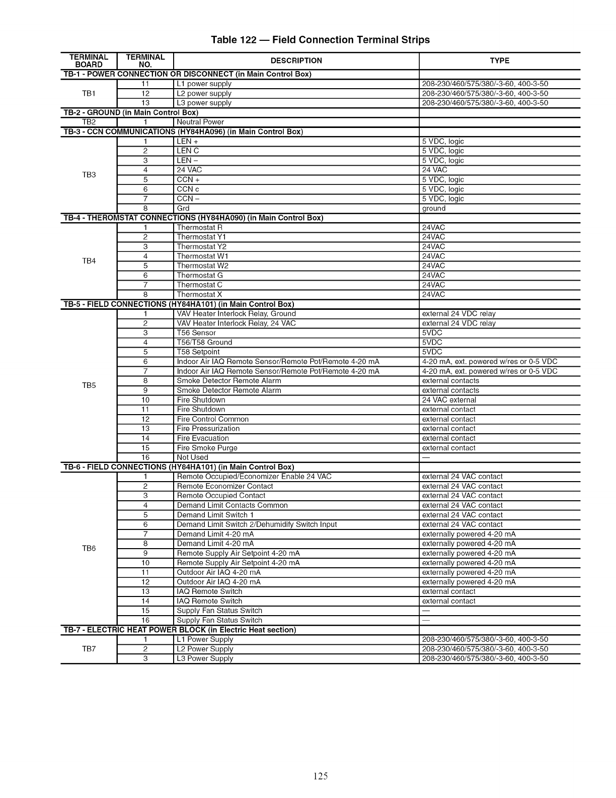
Table 122 -- Field Connection Terminal Strips
TERMINAL I TERMINAL IBOARD NO. DESCRIPTION TYPE
TB-1 - POWER CONNECTION OR DISCONNECT (in Main Control Box)
11 L1 power supply 208-230/460/575/380/-3-60, 400-3-50
TB1 12 L2 power supply 208-230/460/575/380/-3-60, 400-3-50
13 L3 power supply 208-230/460/575/380/-3-60, 400-3-50
TB-2 - GROUND (in Main Control Box)
TB2 I 1 I Neutral Power
TB-3 - CCN COMMUNICATIONS (HY84HA096) (in Main Control Box)
1 LEN + 5 VDC, logic
2 LEN C 5 VDC, logic
3 LEN - 5 VDC, logic
4 24 VAC 24 VAC
TB3 5 CCN + 5 VDC, logic
6 CCN c 5 VDC, logic
7 CCN - 5 VDC, logic
8 Grd ground
TB-4 - THEROMSTAT CONNECTIONS (HY84HA090) (in Main Control Box)
1 Thermostat R 24VAC
2 Thermostat Y1 24VAC
3 Thermostat Y2 24VAC
4 Thermostat W1 24VAC
TB4 5 Thermostat W2 24VAC
6 Thermostat G 24VAC
7 Thermostat C 24VAC
8 Thermostat X 24VAC
TB-5 - FIELD CONNECTIONS (HY84HA101) (in Main Control Box)
1 VAV Heater Interlock Relay, Ground external 24 VDC relay
2 VAV Heater Interlock Relay, 24 VAC external 24 VDC relay
3 T56 Sensor 5VDC
4 T56/T58 Ground 5VDC
5 T58 Setpoint 5VDC
6 Indoor Air IAQ Remote Sensor/Remote Pot/Remote 4-20 mA 4-20 mA, ext. powered w/res or 0-5 VDC
7 Indoor Air IAQ Remote Sensor/Remote Pot/Remote 4-20 mA 4-20 mA, ext. powered w/res or 0-5 VDC
8 Smoke Detector Remote Alarm external contacts
TB5 9 Smoke Detector Remote Alarm external contacts
10 Fire Shutdown 24 VAC external
11 Fire Shutdown external contact
12 Fire Control Common external contact
13 Fire Pressurization external contact
14 Fire Evacuation external contact
15 Fire Smoke Purge external contact
16 Not Used
TB-6 - FIELD CONNECTIONS (HY84HA101) (in Main Control Box)
1 Remote Occupied/Economizer Enable 24 VAC external 24 VAC contact
2 Remote Economizer Contact external 24 VAC contact
3 Remote Occupied Contact external 24 VAC contact
4 Demand Limit Contacts Common external 24 VAC contact
5 Demand Limit Switch 1 external 24 VAC contact
6 Demand Limit Switch 2/Dehumidify Switch Input external 24 VAC contact
7 Demand Limit 4-20 mA externally )owered 4-20 mA
8 Demand Limit 4-20 mA externally )owered 4-20 mA
TB6 9 Remote Supply Air Setpoint 4-20 mA externally )owered 4-20 mA
10 Remote Supply Air Setpoint 4-20 mA externally )owered 4-20 mA
11 Outdoor Air IAQ 4-20 mA externally )owered 4-20 mA
12 Outdoor Air IAQ 4-20 mA externally )owered 4-20 mA
13 IAQ Remote Switch external contact
14 IAQ Remote Switch external contact
15 Supply Fan Status Switch
16 Supply Fan Status Switch
TB-7 - ELECTRIC HEAT POWER BLOCK (in Electric Heat section)
1 L1 Power Supply 208-230/460/575/380/-3-60, 400-3-50
TB7 2 L2 Power Supply 208-230/460/575/380/-3-60, 400-3-50
3 L3 Power Supply 208-230/460/575/380/-3-60, 400-3-50
125
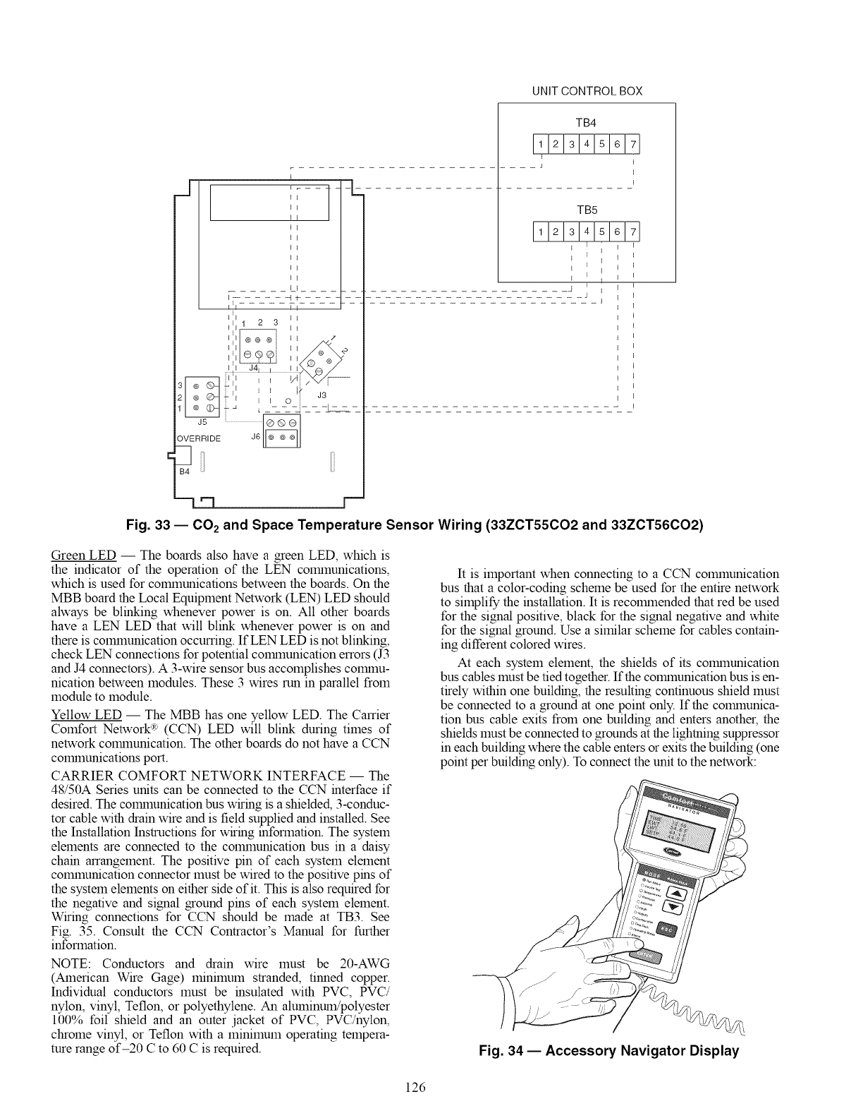
UNIT CONTROL BOX
!I I.....
III I I
i 1 2 3 I
IEk I 2'
r ::
1_ _ L _-----7- - -_
J5 ....................................I®@ol
OVERRIDE J6
TB4
111213141516171
I
I
TB5
11121 IiI 16171
iE E _
E I
_4 1 i
J
Fig. 33 -- CO 2 and Space Temperature Sensor Wiring (33ZCT55CO2 and 33ZCT56CO2)
Green LED -- The boards also have a green LED, which is
the indicator of the operation of the LEN colrnnunications,
which is used for colmnunications between the boards. On the
MBB board the Local Equipment Network (LEN) LED should
always be blinking whenever power is on. All other boards
have a LEN LED that will blink whenever power is on and
there is colmnunication occumng. IfLEN LED is not blinking,
check LEN connections for potential colrnnunication errors (J3
and J4 connectors). A 3-wire sensor bus accomplishes colrnnu-
nication between modules. These 3 wires run in parallel from
module to module.
Yellow LED -- The MBB has one yellow LED. The Carrier
Comfort Network R_(CCN) LED will blink during times of
network colrnnunication. The other boards do not have a CCN
colrnnunications port.
CARRIER COMFORT NETWORK INTERFACE -- The
48/50A Series units can be connected to the CCN interface if
desired. The colrnnunication bus wiring is a shielded, 3-conduc-
tor cable with drain wire and is field supplied and installed. See
the Installation Instructions for wiring information. The system
elements are connected to the colmnunication bus in a daisy
chain arrangement. The positive pin of each system element
colmnunication connector must be wired to the positive pins of
the system elements on either side of it. This is also required for
the negative and signal ground pins of each system element.
Wiring connections for CCN should be made at TB3. See
Fig. 35. Consult the CCN Contractor's Manual for further
information.
NOTE: Conductors and drain wire must be 20-AWG
(American Wire Gage) minimum stranded, tinned copper.
Individual conductors must be insulated with PVC, PVC/
nylon, vinyl, Teflon, or polyethylene. An aluminum/polyester
100% foil shield and an outer jacket of PVC, PVC/nylon,
chrome vinyl, or Teflon with a minimum operating tempera-
rare range of-20 C to 60 C is required.
It is important when connecting to a CCN colmnunication
bus that a color-coding scheme be used for the entire network
to simplify the installation. It is recolrnnended that red be used
for the signal positive, black for the signal negative and white
for the signal ground. Use a similar scheme for cables contain-
ing different colored wires.
At each system element, the shields of its colrnnunication
bus cables must be tied together. If the colrnnunication bus is en-
tirely within one building, the resulting continuous shield must
be connected to a ground at one point only. If the colrnnunica-
tion bus cable exits from one building and enters another, the
shields must be connected to grounds at the lightning suppressor
in each building where the cable enters or exits the building (one
point per building only). To connect the unit to the network:
Fig. 34 -- Accessory Navigator Display
126
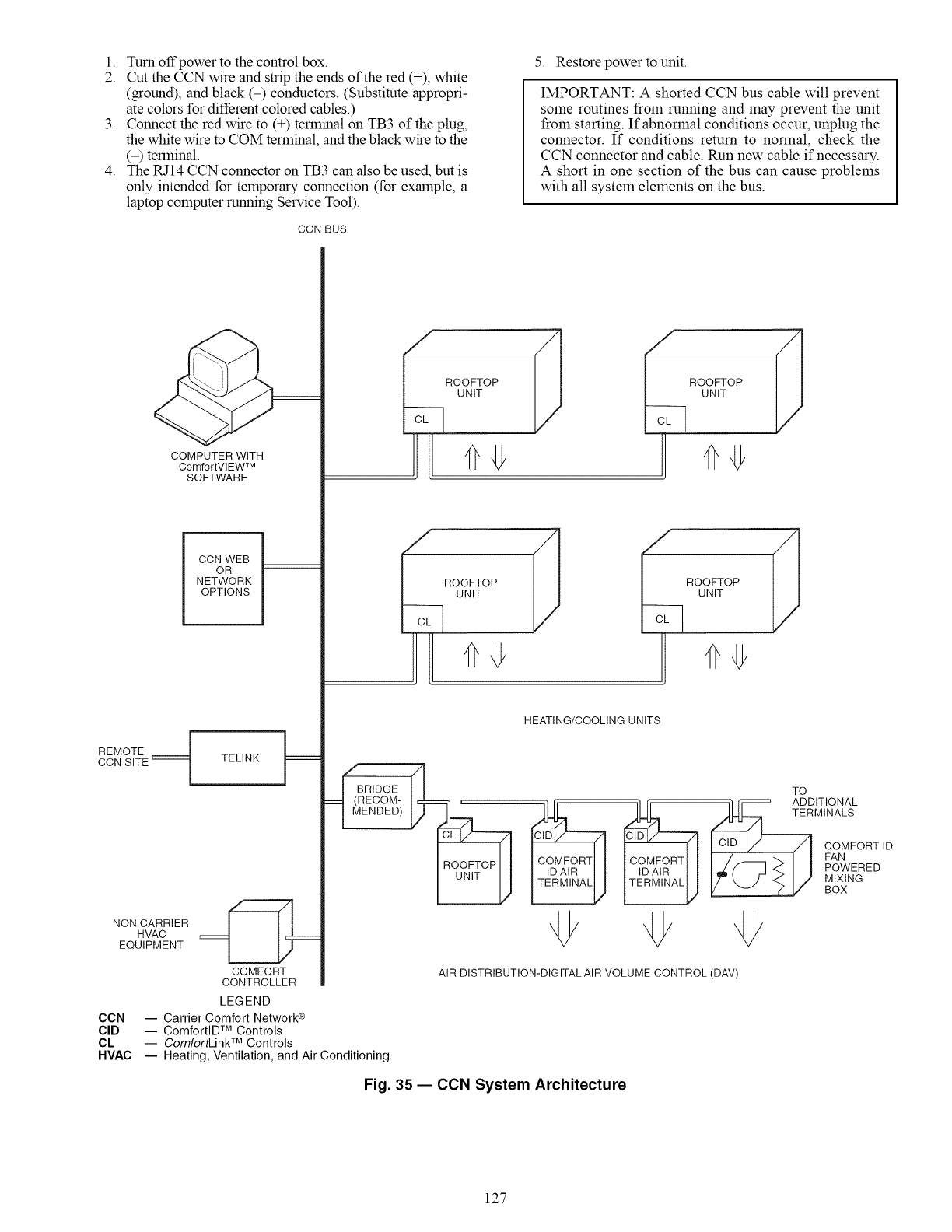
1. Turnoffpowertothecontrolbox.
2. CuttheCCNwireandstriptheendsofthered(+),white
(ground),andblack(-) conductors.(Substituteappropri-
atecolorsfordifferentcoloredcables.)
3. Connecttheredwireto(+)terminalonTB3oftheplug,
thewhitewiretoCOMterminal,andtheblackwiretothe
(-)terminal.
4. TheRJ14CCNconnectoronTB3canalsobeused,butis
onlyintendedfortemporaryconnection(forexample,a
laptopcomputerrunningServiceTool).
CON BUS
5. Restore power to unit.
IMPORTANT: A shorted CCN bus cable will prevent
some routines from running and may prevent the unit
from starting. If abnormal conditions occur, unplug the
connector. If conditions return to normal, check the
CCN connector and cable. Run new cable if necessary.
A short in one section of the bus can cause problems
with all system elements on the bus.
REMOTE
CCN SITE
NON CARRIER
HVAC
EQUIPMENT
CON
CID
eL
HVAC
COMPUTER WITH
ComfortVlEW TM
SOFTWARE
CCN WEB
OR
NETWORK
OPTIONS
TELINK F /
BRIDGE
(RECOM-
MENDED)
ROOFTOP ROOFTOP
UNIT UNIT
ROuOFTOP ROuON_TOP
HEATING/COOLING UNITS
COMFORT
CONTROLLER
LEGEND
-- Carrier Comfort Network®
-- ComfortlDTM Controls
-- ComfortLinkTM Controls
-- Heating, Ventilation, and Air Conditioning
TO ITIONAL
MINALS
COMFORT ID
FAN
POWERED
MIXING
BOX
AIR DISTRIBUTION-DIGITAL AIR VOLUME CONTROL (DAV)
Fig. 35 -- CON System Architecture
127
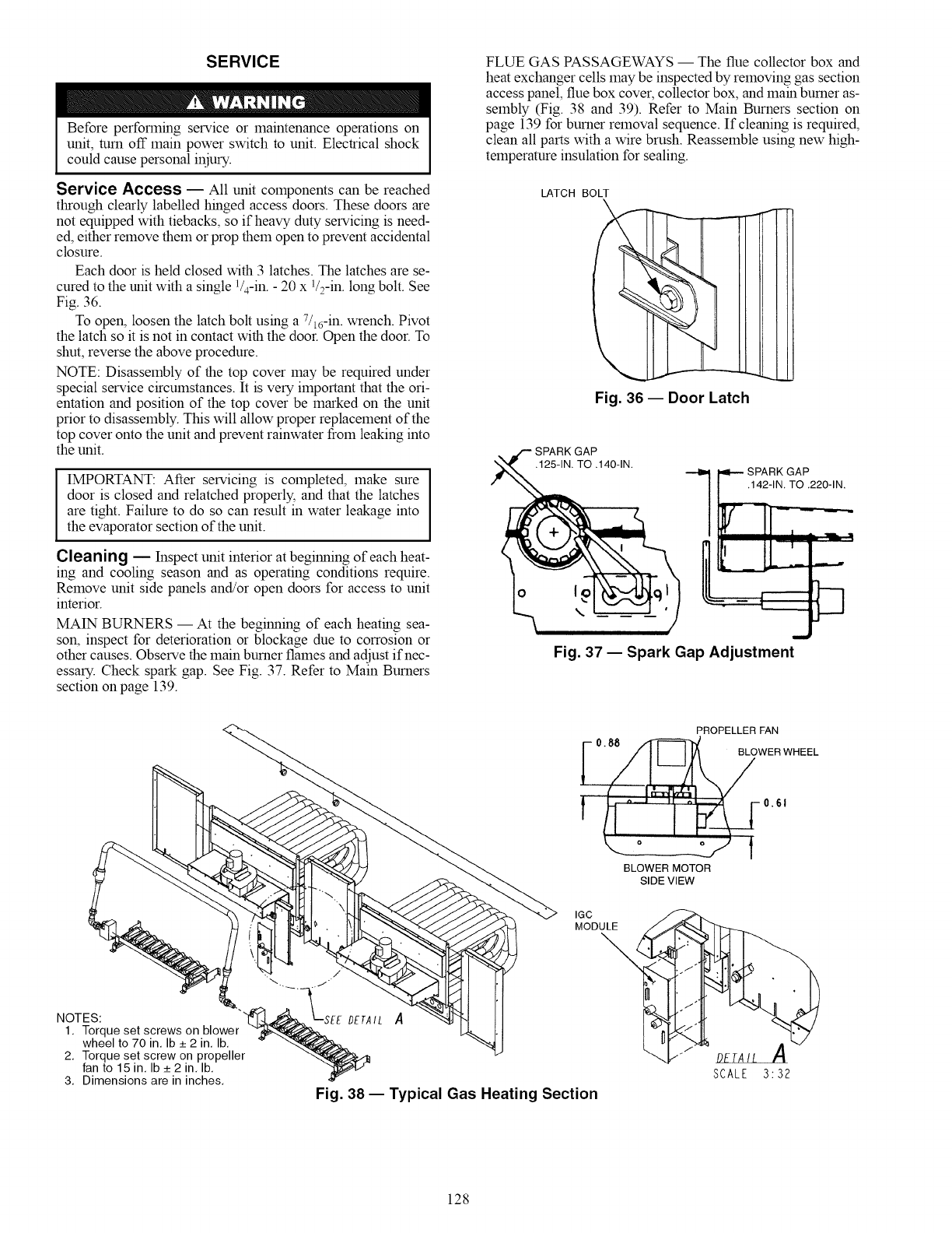
SERVICE
Before performing service or maintenance operations on
unit, turn off main power switch to unit. Electrical shock
could cause personal iniury.
Service Access -- All unit components can be reached
through clearly labelled hinged access doors. These doors are
not equipped with tiebacks, so if heavy duty servicing is need-
ed, either remove them or prop them open to prevent accidental
closure.
Each door is held closed with 3 latches. The latches are se-
cured to the unit with a single 1/4-in. - 20 x 1/:-in. long bolt. See
Fig. 36.
To open, loosen the latch bolt using a 7/16-in. wrench. Pivot
the latch so it is not in contact with the door. Open the door. To
shut, reverse the above procedure.
NOTE: Disassembly of the top cover may be required under
special service circumstances. It is very important that the ori-
entation and position of the top cover be marked on the unit
prior to disassembly. This will allow proper replacement of the
top cover onto the unit and prevent rainwater from leaking into
the unit.
IMPORTANT: After servicing is completed, make sure
door is closed and relatched properly, and that the latches
are tight. Failure to do so can result in water leakage into
the evaporator section of the unit.
Cleaning -- Inspect unit interior at beginning of each heat-
ing and cooling season and as operating conditions require.
Remove unit side panels and/or open doors for access to unit
interior.
MAIN BURNERS -- At the beginning of each heating sea-
son, inspect for deterioration or blockage due to corrosion or
other causes. Observe the main burner flames and adjust if nec-
essary. Check spark gap. See Fig. 37. Refer to Main Burners
section on page 139.
FLUE GAS PASSAGEWAYS -- The flue collector box and
heat exchanger cells may be inspected by removing gas section
access panel, flue box cover, collector box, and main burner as-
sembly (Fig. 38 and 39). Refer to Main Burners section on
page 139 for burner removal sequence. If cleaning is required,
clean all parts with a wire brush. Reassemble using new high-
temperature insulation for sealing.
LATCH BOLT
\
Fig. 36 -- Door Latch
SPARK GAP
.125-1N TO .140-IN SPARK GAP
.142-1N. TO .220-1N.
Fig. 37 -- Spark Gap Adjustment
PROPELLER FAN
'i
BLOWER MOTOR
SIDE VIEW
IGC
MODULE
\
/
q
NOTES L -EE ¢L
_SEEDETA1,Torque set screws on blower
wheel to 70 in, Ib _+2 in, Ib, _ "-<"_
2, Torque set screw on propeller '-4.._
fan to 15 in, Ib _+2 in, Ib,
3, Dimensions are in inches, '_ Fig. 38 -- Typical Gas Heating Section
DETAIL A
SCALE 3:32
128
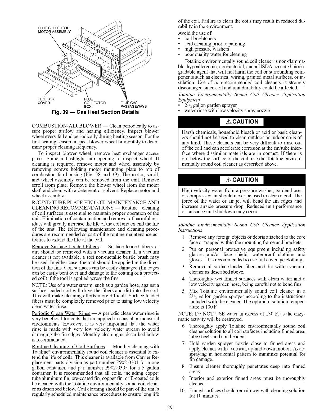
FLUE COLLECTOR
MOTOR ASSEMBLY
FLUE BOX FLUE
COVER COLLECTOR FLUE GAS
BOX PASSAGEWAYS
Fig. 39 -- Gas Heat Section Details
of the coil. Failure to clean the coils may result in reduced du-
rability in the enviromnent.
Avoid the use of:
• coil brighteners
• acid cleaning prior to painting
• high pressure washers
• poor quality water for cleaning
Totaline enviromnentally sound coil cleaner is non-flalrnna-
ble, hypoallergenic, nonbacterial, and a USDA accepted biode-
gradable agent that will not harm the coil or surrounding coin-
ponents such as electrical wiring, painted metal surfaces, or in-
sulation. Use of non-recolmnended coil cleaners is strongly
discouraged since coil and unit durability could be affected.
Yotaline Envilvnmentally 3_und (_il ('leaner Application
Equipment
• 21/2 gallon garden sprayer
• water rinse with low velocity spray nozzle
COMBUSTION-AIR BLOWER -- Clean periodically to as-
sure proper airflow and heating efficiency. Inspect blower
wheel every fall and periodically during heating season. For the
first heating season, inspect blower wheel bi-monthly to deter-
mine proper cleaning frequency.
To inspect blower wheel, remove heat exchanger access
panel. Shine a flashlight into opening to inspect wheel. If
cleaning is required, remove motor and wheel assembly by
removing screws holding motor mounting plate to top of
combustion fan housing (Fig. 38 and 39). The motor, scroll,
and wheel assembly can be removed from the unit. Remove
scroll from plate. Remove the blower wheel from the motor
shaft and clean with a detergent or solvent. Replace motor and
wheel assembly.
ROUND TUBE PLATE FIN COIL MA_TENANCE AND
CLEANING RECOMMENDATIONS -- Routine cleaning
of coil surfaces is essential to maintain proper operation of the
unit. Elimination of contamination and removal of harmful res-
idues will greatly increase the life of the coil and extend the life
of the unit. The following maintenance and cleaning proce-
dures are recolmnended as part of the routine maintenance ac-
tivities to extend the life of the coil.
Remove Surface Loaded Fibers -- Surface loaded fibers or
dirt should be removed with a vacuum cleaner. If a vacuum
cleaner is not available, a soft non-metallic bristle brash may
be used. In either case, the tool should be applied in the direc-
tion of the fins. Coil surfaces can be easily damaged (fin edges
can be easily bent over and damage to the coating of a protect-
ed coil) if the tool is applied across the fins.
NOTE: Use of a water stream, such as a garden hose, against a
surface loaded coil will drive the fibers and dirt into the coil.
This will make cleaning efforts more difficult. Surface loaded
fibers must be completely removed prior to using low velocity
clean water rinse.
Periodic Clean Water Rinse -- A periodic clean water rinse is
very beneficial for coils that are applied in coastal or industrial
enviromnents. However, it is very important that the water
rinse is made with very low velocity water stream to avoid
damaging the fin edges. Monthly cleaning as described below
is reconnnended.
Routine Cleaning of Coil Surfaces -- Monthly cleaning with
Totaline:R:enviromnentally sound coil cleaner is essential to ex-
tend the life of coils. This cleaner is available from Carrier Re-
placement parts division as part number P902-0301 for a one
gallon container, and part number P902-0305 for a 5 gallon
container. It is recolmnended that all coils, including copper
robe aluminum fin, pre-coated fin, copper fin, or E-coated coils
be cleaned with the Totaline enviromnentally sound coil clean-
er as described below. Coil cleaning should bepart of the unit's
regularly scheduled maintenance procedures to ensure long life
Harsh chemicals, household bleach or acid or basic clean-
ers should not be used to clean outdoor or indoor coils of
any kind. These cleaners can be very difficult to rinse out
of the coil and can accelerate corrosion at the fin!robe inter-
face where dissimilar materials are in contact. If there is
dirt below the surface of the coil, use the Totaline environ-
mentally sound coil cleaner as described above.
High velocity water from a pressure washer, garden hose,
or compressed air should never be used to clean a coil. The
force of the water or air jet will bend the fin edges and
increase airside pressure drop. Reduced unit performance
or nuisance unit shutdown may occur.
Tomline Envitvnmenmlly 3_und (_il ('leaner Application
Instructions
1. Remove any foreign objects or debris attached to the core
face or trapped within the mounting frame and brackets.
2. Put on personal protective equipment including safety
glasses and/or face shield, waterproof clothing and
gloves. It is recolmnended to use full coverage clothing.
3. Remove all surface loaded fibers and dirt with a vacuum
cleaner as described above.
4.
5.
Thoroughly wet finned surfaces with clean water and a
low velocity garden hose, being careful not to bend fins.
Mix Totaline enviromnentally sound coil cleaner in a
21/2 gallon garden sprayer according to the instructions
included with the cleaner. The optimum solution temper-
amre is 100 E
NOTE: Do NOT USE water in excess of 130 F, as the enzy-
matic activity will be destroyed.
6. Thoroughly apply Totaline enviromnentally sound coil
cleaner solution to all coil surfaces including finned area,
robe sheets and coil headers.
7. Hold garden sprayer nozzle close to finned areas and
apply cleaner with a vertical, up-and-down motion. Avoid
spraying in horizontal pattern to minimize potential for
fm damage.
8. Ensure cleaner thoroughly penetrates deep into finned
areas.
9. Interior and exterior finned areas must be thoroughly
cleaned.
10. Finned surfaces should remain wet with cleaning solution
for 10 minutes.
129
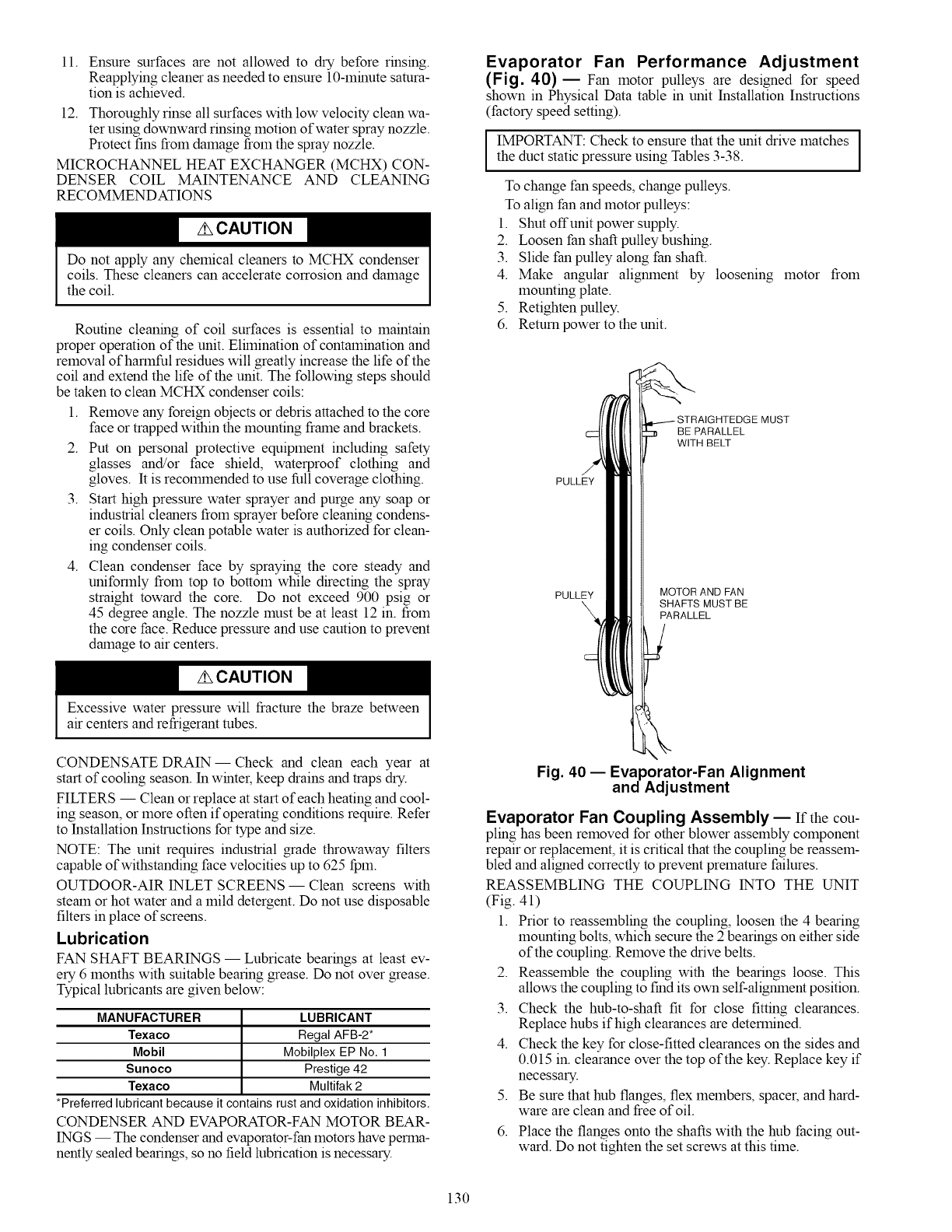
11.Ensuresurfacesarenotallowedto drybeforerinsing.
Reapplyingcleanerasneededtoensure10-minutesatura-
tionisachieved.
12.Thoroughlyrinseallsurfaceswithlowvelocitycleanwa-
terusingdownwardrinsingmotionofwaterspraynozzle.
Protectfinsfromdamagefromthespraynozzle.
MICROCHANNELHEATEXCHANGER(MCHX)CON-
DENSERCOIL MAINTENANCEAND CLEANING
RECOMMENDATIONS
Do not apply any chemical cleaners to MCHX condenser
coils. These cleaners can accelerate corrosion and damage
the coil.
Routine cleaning of coil surfaces is essential to maintain
proper operation of the unit. Elhnination of contamination and
removal of harmful residues will greatly increase the life of the
coil and extend the life of the unit. The following steps should
be taken to clean MCHX condenser coils:
1. Remove any foreign objects or debris attached to the core
face or trapped within the mounting frame and brackets.
2. Put on personal protective equipment including safety
glasses and/or face shield, waterproof clothing and
gloves. It is recolmnended to use full coverage clothing.
3. Start high pressure water sprayer and purge any soap or
industrial cleaners from sprayer before cleaning condens-
er coils. Only clean potable water is authorized for clean-
ing condenser coils.
4. Clean condenser face by spraying the core steady and
uniformly from top to bottom while directing the spray
straight toward the core. Do not exceed 900 psig or
45 degree angle. The nozzle must be at least 12 in. from
the core face. Reduce pressure and use caution to prevent
damage to air centers.
Excessive water pressure will fracture the braze between
air centers and refrigerant tubes.
CONDENSATE DRAIN--Check and clean each year at
start of cooling season. In winter, keep drains and traps dry.
FILTERS -- Clean or replace at start of each heating and cool-
ing season, or more often if operating conditions require. Refer
to Installation Instructions for type and size.
NOTE: The unit requires industrial grade throwaway filters
capable of withstanding face velocities up to 625 fpm.
OUTDOOR-AIR 1NLET SCREENS -- Clean screens with
steam or hot water and a mild detergent. Do not use disposable
filters in place of screens.
Lubrication
FAN SHAFT BEARINGS -- Lubricate bearings at least ev-
ery 6 months with suitable bearing grease. Do not over grease.
Typical lubricants are given below:
MANUFACTURER LUBRICANT
Texaco Regal AFB-2*
Mobil Mobilplex EP No. 1
Sunoco Prestige 42
Texaco Multifak 2
*Preferred lubricant because it contains rust and oxidation inhibitors.
CONDENSER AND EVAPORATOR-FAN MOTOR BEAR-
INGS -- The condenser and evaporator-fan motors have perma-
nently sealed bearings, so no field lubrication is necessary.
Evaporator Fan Performance Adjustment
(Fig. 40) EFan motor pulleys are designed for speed
shown in Physical Data table in unit Installation Instructions
(factory speed setting).
IMPORTANT: Check to ensure that the unit drive matches
the duct static pressure using Tables 3-38.
To change fan speeds, change pulleys.
To align fan and motor pulleys:
1. Shut offunit power supply.
2. Loosen fan shaft pulley bushing.
3. Slide fan pulley along fan shaft.
4. Make angular aligmnent by loosening
mounting plate.
5. Retighten pulley.
6. Return power to the unit.
motor from
PULLEY
PULLEY
BE PARALLEL
WITH BELT
MOTOR AND FAN
SHAFTS MUST BE
PARALLEL
Fig. 40- Evaporator-Fan Alignment
and Adjustment
Evaporator Fan Coupling Assembly EIf the cou-
pling has been removed for other blower assembly component
repair or replacement, it is critical that the coupling be reassem-
bled and aligned correctly to prevent premature failures.
REASSEMBLING THE COUPL1NG 1NTO THE UNIT
(Fig. 41)
1. Prior to reassembling the coupling, loosen the 4 bearing
mounting bolts, which secure the 2 bearings on either side
of the coupling. Remove the drive belts.
2. Reassemble the coupling with the bearings loose. This
allows the coupling to find its own self-aliginnent position.
3. Check the hub-to-shaft fit for close fitting clearances.
Replace hubs if high clearances are determined.
4. Check the key for close-fitted clearances on the sides and
0.015 in. clearance over the top of the key. Replace key if
necessary.
Be sure that hub flanges, flex members, spacer, and hard-
ware are clean and free ofoil.
5.
6. Place the flanges onto the shafts with the hub facing out-
ward. Do not tighten the set screws at this time.
130
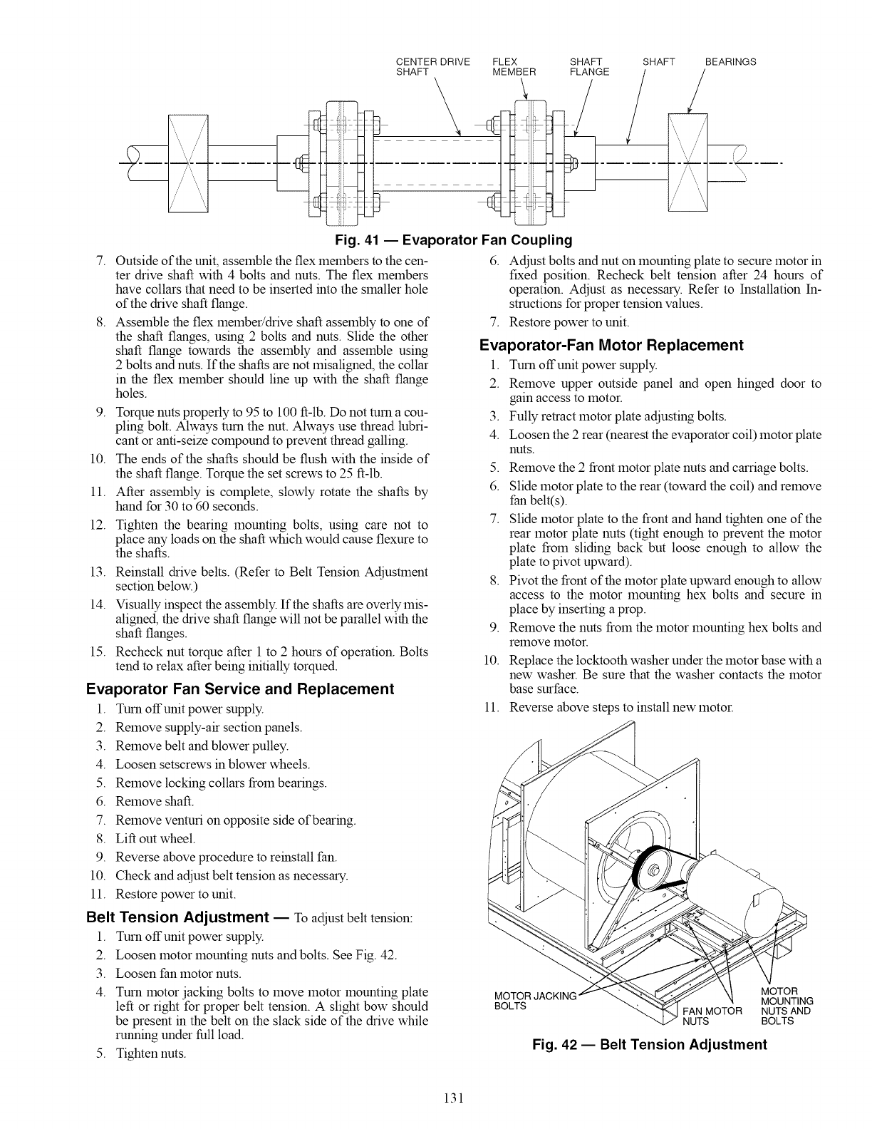
E ===_ _= E
CENTER DRIVE
SHAFT FLEX
MEMBER SHAFT SHAFT
FLANGE BEARINGS
7.
8.
Fig. 41 -- Evaporator Fan Coupling
Outside of the unit, assemble the flex members to the cen-
ter drive shaft with 4 bolts and nuts. The flex members
have collars that need to be inserted into the smaller hole
of the drive shaft flange.
Assemble the flex member/drive shaft assembly to one of
the shaft flanges, using 2 bolts and nuts. Slide the other
shaft flange towards the assembly and assemble using
2 bolts and nuts. If the shafts are not misaligned, the collar
in the flex member should line up with the shaft flange
holes.
9. Torque nuts properly to 95 to 100 ft-lb. Do not turn a cou-
pling bolt. Always turn the nut. Always use thread lubri-
cant or anti-seize compound to prevent thread galling.
10. The ends of the shafts should be flush with the inside of
the shaft flange. Torque the set screws to 25 ft-Ib.
11. After assembly is complete, slowly rotate the shafts by
hand for 30 to 60 seconds.
12. Tighten the bearing mounting bolts, using care not to
place any loads on the shaft which would cause flexure to
the shafts.
13. Reinstall drive belts. (Refer to Belt Tension Adjustlnent
section below.)
14. Visually inspect the assembly. If the shafts are overly mis-
aligned, the drive shaft flange will not be parallel with the
shaft flanges.
15. Recheck nut torque after 1 to 2 hours of operation. Bolts
tend to relax after being initially torqued.
Evaporator Fan Service and Replacement
1. Turn offunit power supply.
2. Remove supply-air section panels.
3. Remove belt and blower pulley.
4. Loosen setscrews in blower wheels.
6. Adjust bolts and nut on mounting plate to secure motor in
fixed position. Recheck belt tension after 24 hours of
operation. Adjust as necessary. Refer to Installation In-
structions for proper tension values.
7. Restore power to unit.
Evaporator-Fan Motor Replacement
1. Turn offunit power supply.
2. Remove upper outside panel and open hinged door to
gain access to motor.
3. Fully retract motor plate adjusting bolts.
4. Loosen the 2 rear (nearest the evaporator coil) motor plate
nuts.
5. Remove the 2 front motor plate nuts and carriage bolts.
6. Slide motor plate to the rear (toward the coil) and remove
fan belt(s).
7. Slide motor plate to the front and hand tighten one of the
rear motor plate nuts (tight enough to prevent the motor
plate from sliding back but loose enough to allow the
plate to pivot upward).
8. Pivot the front of the motor plate upward enough to allow
access to the motor mounting hex bolts and secure in
place by inserting a prop.
9. Remove the nuts from the motor mounting hex bolts and
remove lrlotor.
10. Replace the locktooth washer under the motor base with a
new washer. Be sure that the washer contacts the motor
base surface.
11. Reverse above steps to install new motor.
5. Remove locking collars from bearings.
6. Remove shaft.
7. Remove venturi on opposite side of bearing.
8. Lift out wheel.
9. Reverse above procedure to reinstall fan.
10. Check and adjust belt tension as necessary.
11. Restore power to unit.
Belt Tension Adjustment E To adjust belt tension:
1. Turn offunit power supply.
2. Loosen motor mounting nuts and bolts. See Fig. 42.
3. Loosen fan motor nuts.
4. Turn motor jacking bolts to move motor mounting plate
left or right for proper belt tension. A slight bow should
be present in the belt on the slack side of the drive while
running under full load.
5. Tighten nuts.
MOTOR MOTOR
MOUNTING
BOLTS FAN MOTOR NUTS AND
NUTS BOLTS
Fig. 42 -- Belt Tension Adjustment
131
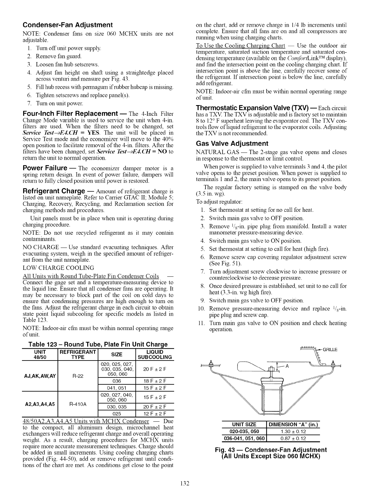
Condenser-Fan Adjustment
NOTE: Condenser fans on size 060 MCHX units are not
adjustable.
1. Turn offunit power supply.
2. Remove fan guard.
3. Loosen fan hub setscrews.
4. Adjust fan height on shaft using astraightedge placed
across venturi and measure per Fig. 43.
5. Fill hub recess with perlnagum if rubber hubcap is missing.
6. Tighten setscrews and replace panel(s).
7. Turn on unit power.
Four-Inch Filter Replacement- The 4-Inch Filter
Change Mode variable is used to service the unit when 4-in.
filters are used. When the filters need to be changed, set
Service rest-cE4.CH =YES. The unit will be placed in
Service Test mode and the economizer will move to the 40%
open position to facilitate removal of the 4-in. filters. After the
filters have been changed, set Service Test---_E4. (2Tt = NO to
return the unit to normal operation.
Power Failure- The economizer damper motor is a
spring return design. In event of power failure, dampers will
return to fully closed position until power is restored.
Refrigerant Charge _Amount of refrigerant charge is
listed on unit nameplate. Refer to Carrier GTAC II; Module 5;
Charging, Recovery, Recycling, and Reclamation section for
charging methods and procedures.
Unit panels must be in place when unit is operating during
charging procedure.
NOTE: Do not use recycled refrigerant as it may contain
contaminants.
NO CHARGE- Use standard evacuating techniques. After
evacuating system, weigh in the specified amount of refriger-
ant from the unit nameplate.
LOW CHARGE COOLING
All Units with Round Tube-Plate Fin Condenser Coils --
Connect the gage set and a temperature-measuring device to
the liquid line. Ensure that all condenser fans are operating. It
may be necessary to block part of the coil on cold days to
ensure that condensing pressures are high enough to turn on
the fans. Adjust the refrigerant charge in each circuit to obtain
state point liquid subcooling for specific models as listed in
Table 123.
NOTE: Indoor-air cfm must be within normal operating range
of unit.
Table 123 - Round Tube, Plate Fin Unit Charge
UNIT REFRIGERANT SIZE LIQUID
48/50 TYPE SUBCOOLING
020, 025, 027,
030,035,040, 20 F_+2 F
AJ,AK,AW,AY R-22 050, 060
036 18F_+2F
041,051 15 F_+2 F
020,027, 040, 15 F_+2 F
050,060
A2,A3,A4,A5 R-410A 030,035 20 F _+2 F
025 12F_+2F
48/50A2_A3 _4_A5 Units with MCHX Condenser -- Due
to the compact, all aluminum design, microchannel heat
exchangers will reduce refrigerant charge and overall operating
weight. As a result, charging procedures for MCHX units
require more accurate measurement techniques. Charge should
be added in small increments. Using cooling charging charts
provided (Fig. 44-50), add or remove refrigerant until condi-
tions of the chart are met. As conditions get close to the point
on the chart, add or remove charge in 1/4 Ib increments until
complete. Ensure that all fans are on and all compressors are
running when using charging charts.
To Use the Cooling Charging Chart -- Use the outdoor air
temperature, saturated suction temperature and saturated con-
densing temperature (available on the (_n_fortLink TM display),
and find the intersection point on the cooling charging chart. If
intersection point is above the line, carefully recover some of
the refrigerant. If intersection point is below the line, carefully
add refrigerant.
NOTE: Indoor-air cfm must be within normal operating range
of unit.
Thermostatic Expansion Valve (TXV) -- Each circuit
has a TXV. The TXV is adjustable and is factory set to maintain
8 to 12° F superheat leaving the evaporator coil. The TXV con-
trols flow of liquid refrigerant to the evaporator coils. Adjusting
the TXV is not reconnnended.
Gas Valve Adjustment
NATURAL GAS -- The 2-stage gas valve opens and closes
in response to the thermostat or limit control.
When power is supplied to valve terminals 3 and 4, the pilot
valve opens to the preset position. When power is supplied to
terminals 1 and 2, the main valve opens to its preset position.
The regular factory setting is stamped on the valve body
(3.5 in. wg).
To adjust regulator:
1. Set thermostat at setting for no call for heat.
2. Switch main gas valve to OFF position.
3. Remove l/s-in, pipe plug from manifold. Install a water
manometer pressure-measuring device.
4. Switch main gas valve to ON position.
5. Set thermostat at setting to call for heat (high fire).
6. Remove screw cap covering regulator adjustment screw
(See Fig. 51).
7. Turn adjustment screw clockwise to increase pressure or
counterclockwise to decrease pressure.
8. Once desired pressure is established, set unit to no call for
heat (3.3-in. wg high fire).
9. Switch main gas valve to OFF position.
10. Remove pressure-measuring device and replace l/s-in.
pipe plug and screw cap.
11. Turn main gas valve to ON position and check heating
operation.
UNIT SIZE IDIMENSION "A" (in.)
020-035, 050 1.30 _+0.12
036-041,051,060 0.87 _+0.12
Fig. 43 -- Condenser-Fan Adjustment
(All Units Except Size 060 MCHX)
132
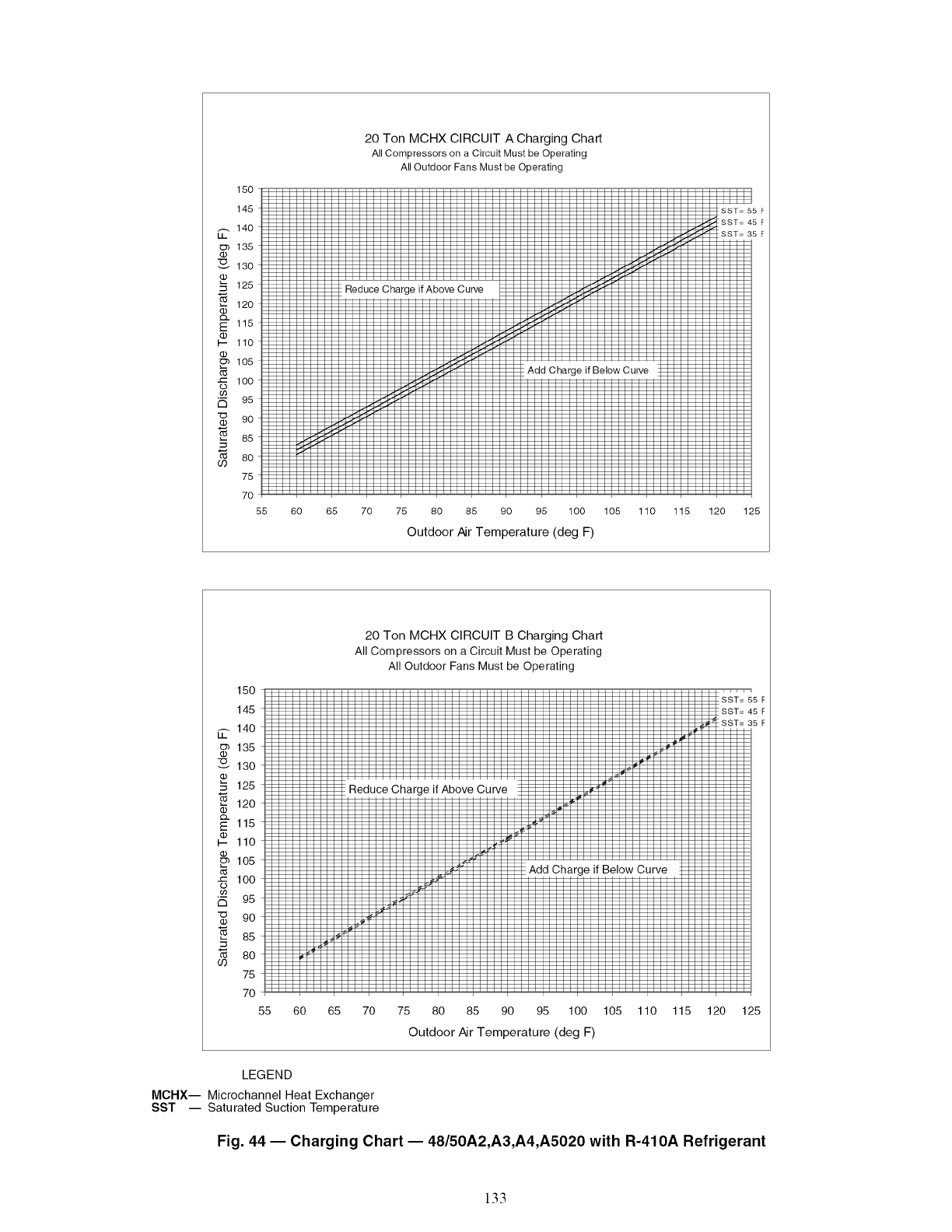
150
145
_.. 140
135
130
d3
._ 125
120
_- 115
I-- 110
105
1O0
95
-_ 9o
a5
so
75
7O
55
20 Ton MCHX CIRCUIT A Charging Chart
All Compressors on a Circuit Must be Operating
All Outdoor Fans Must be Operating
Reduce Charge if Above Curve
Add Charge if Below Curve
60 65 70 75 80 85 90 95 100 105 110
Outdoor Air Temperature (deg F)
115 120 125
150
145
_. 140
135
130
125
120
_" 115
110
105
i 100
95
-_ 9o
85
8o
75
7O
55
20 Ton MCHX CIRCUIT B Charging Chart
All Compressors on a Circuit Must be Operating
All Outdoor Fans Must be Operating
i Reduce Charge if Above Curve
60 65 70 75 80 85 90 95 100 105
Outdoor Air Temperature (deg F)
Curve
5F
5F
5F
110 115 120 125
LEGEND
MCHX-- Microchannel Heat Exchanger
SST -- Saturated Suction Temperature
Fig. 44 -- Charging Chart -- 48/50A2,A3,A4,A5020 with R-410A Refrigerant
133
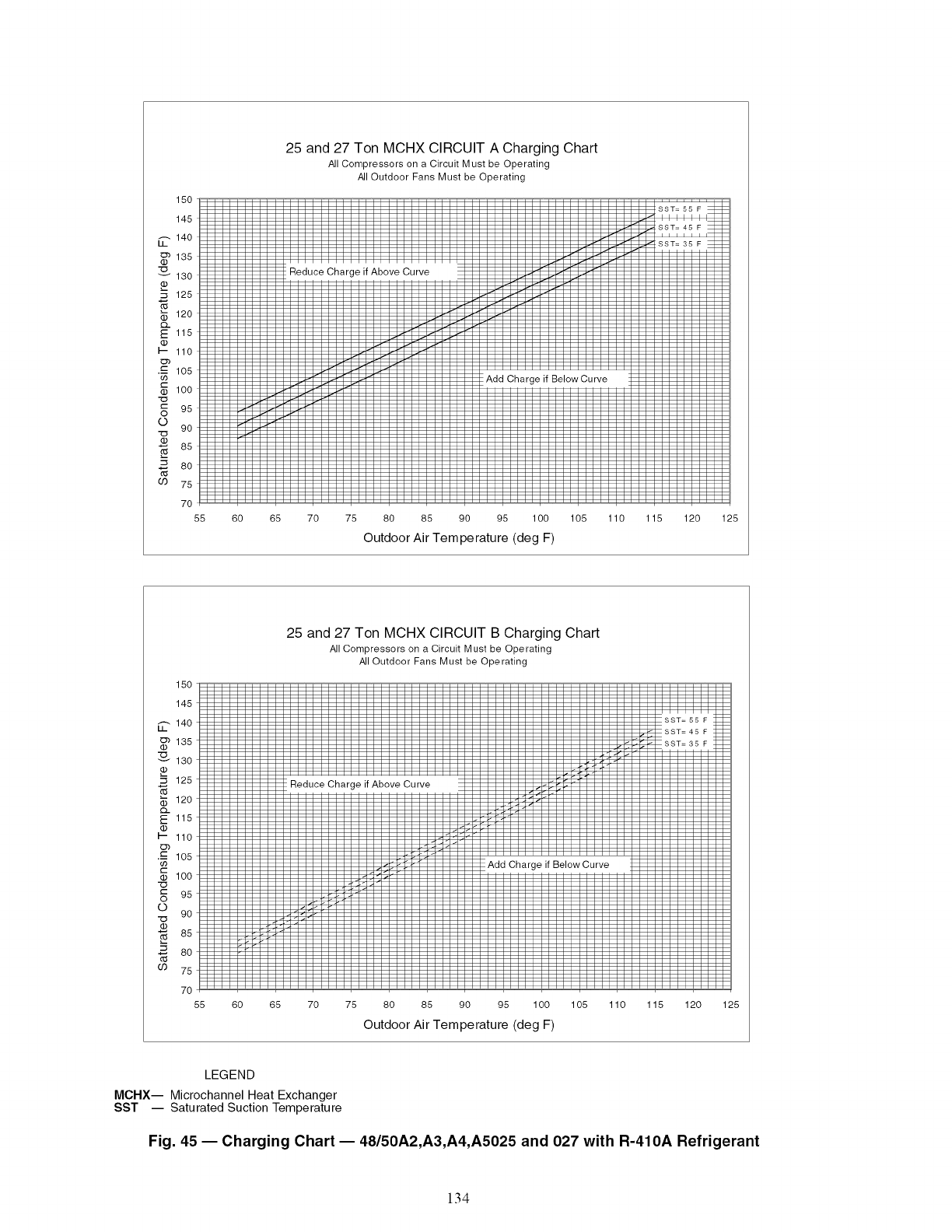
15O
145
_-- 140
_'_ 135
'130
125
120
Q..
E 115
_o._ 110
•_ 105
100
-_ g5
o go
85
80
O0 75
7O
55
25 and 27 Ton MCHX CIRCUIT A Charging Chart
All Compressors on a Circuit Must be Operating
All Outdoor Fans Must be Operating
Reduce Charge if Above Curve
!Add Charge if Below Curve
60 65 70 75 80 85 90 95 100 105 110 115 120 125
Outdoor Air Temperature (deg F)
15O
145
_- 140
¢E_ 135
130
125
_ 120
ffl.
E 115
_cj_ 110
•_ 105
100
_ g5
o go
_ 85
_ 8o
69 75
7O
55
25 and 27 Ton MCHX CIRCUIT B Charging Chart
All Compressors on a Circuit Must be Operating
All Outdoor Fans Must be Operating
Reduce Charge if Above Curve
Add Charge if Below Curve
60 65 70 75 80 85 90 95 100 105 110 115 120 125
Outdoor Air Temperature (deg F)
LEGEND
MCHX-- Microchannel Heat Exchanger
SST -- Saturated Suction Temperature
Fig. 45 -- Charging Chart -- 48/50A2,A3,A4,A5025 and 027 with R-410A Refrigerant
134
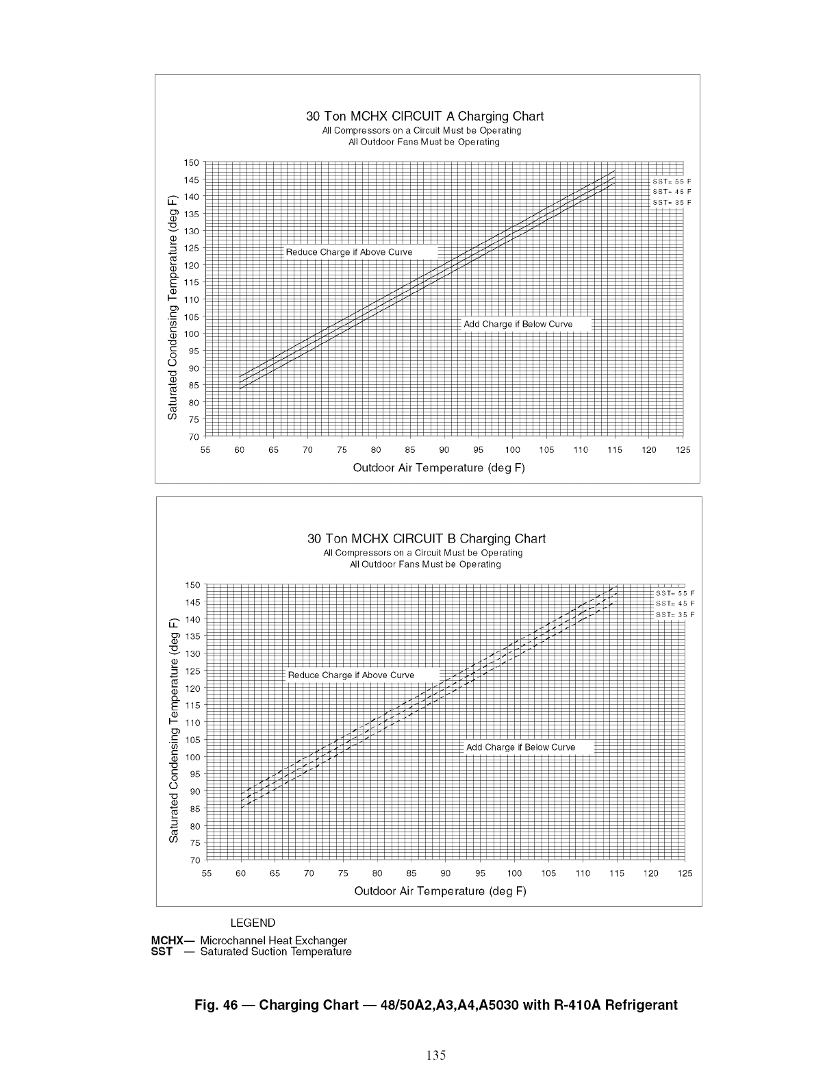
150
145
_-, 140
_'_ 135
-_130
125
120
115
110
•_ 105
_) 100
-_ 95
0 90
85
2o8O
75
7O
55 60
30 Ton MCHX CIRCUIT A Charging Chart
All Compressors on a Circuit Must be Operating
All Outdoor Fans Must be Operating
- Reduce Charge if Above Curve
Add Charge if Below Curve
65 70 75 80 85 90 95 100 105 110 115 120
Outdoor Air Temperature (deg F)
:5_ F
:4! F
:3! F
125
150
145
_. 14o
135
130
125
120
Q.
115
110
._ 105
100
95
9o
85
89
69 75
7O
55
30 Ton MCHX CIRCUIT B Charging Chart
All Compressors on a Circuit Must be Operating
All Outdoor Fans Must be Operating
i Reduce Charge if Above Curve
Add Charge if Below Curve
60 65 70 75 80 85 90 95 100 105 110 115 120
Outdoor Air Temperature (deg F)
LEGEND
MCHX-- Microchannel Heat Exchanger
SST -- Saturated Suction Temperature
....f.......
_5! F
_4! F
_3! F
125
Fig. 46- Charging Chart -- 48/50A2,A3,A4,A5030 with R-410A Refrigerant
135
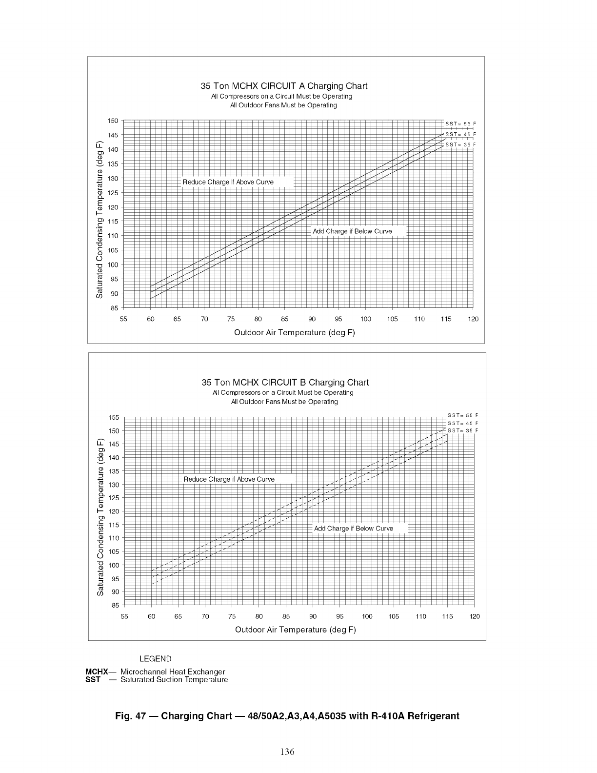
150
145
140
-135
130
_c2.125
120
115
"; 110
105
©
-'_ 100
95
9o
85
55
35 Ton MCHX CIRCUIT A Charging Chart
All Compressors on a Circuit Must be Operating
All Outdoor Fans Must be Operating
Reduce Char{ Above Curve
Charge if Below Curve
60 65 70 75 80 85 90 95
Outdoor Air Temperature (deg F)
:SST=55
;SST=45
SST=
F
F
F
100 105 110 115 120
155
150
145
140
135
130
_"125
120
•_ 115
110
105
"_ 100
95
9o
85
35 Ton MCHX CIRCUIT B Charging Chart
All Compressors on a Circuit Must be Operating
All Outdoor Fans Must be Operating
Reduce Charge if Above Curve
if Below Curve
55 60 65 70 75 80 85 90 95 100 105 110 115
Outdoor Air Temperature (deg F)
SST=
SST=
SST=
55
45
35
120
LEGEND
MCHX-- Microchannel Heat Exchanger
SST -- Saturated Suction Temperature
Fig. 47- Charging Chart -- 48/50A2,A3,A4,A5035 with R-410A Refrigerant
136

150
145
14O
135
130
125
120
115
110
105
100
95
9O
85
8O
75
70
55
40 Ton MCHX Charging Chart
All Compressors on a Circuit Must be Operating
All Outdoor Fans Must be Operating
Reduce Charge if Above Curve
60 65 70 75 80 85 90 95 100 105 110 115 120 125
Outdoor Air Temperature (deg F)
LEGEND
MCHX-- Microchannel Heat Exchanger
SST -- Saturated Suction Temperature
Fig. 48- Charging Chart- 48/50A2,A3,A4,A5040 with R-410A Refrigerant
150
145
_- 140
o_ 135
'130
125
120
Q_
115
110
•_ 105
100
95
9o
8s
8o
°9 75
7O
55
50 Ton MCHX Charging Chart
All Compressors on a Circuit Must be Operating
All Outdoor Fans Must be Operating
Reduce Charge if Above Curve
60 65 70 75 80 85 90 95 100 105 110 115 120 125
Outdoor Air Temperature (deg F)
LEGEND
MCHX-- Microchannel Heat Exchanger
SST -- Saturated Suction Temperature
Fig. 49 -- Charging Chart- 48/50A2,A3,A4,A5050 with R-410A Refrigerant
137
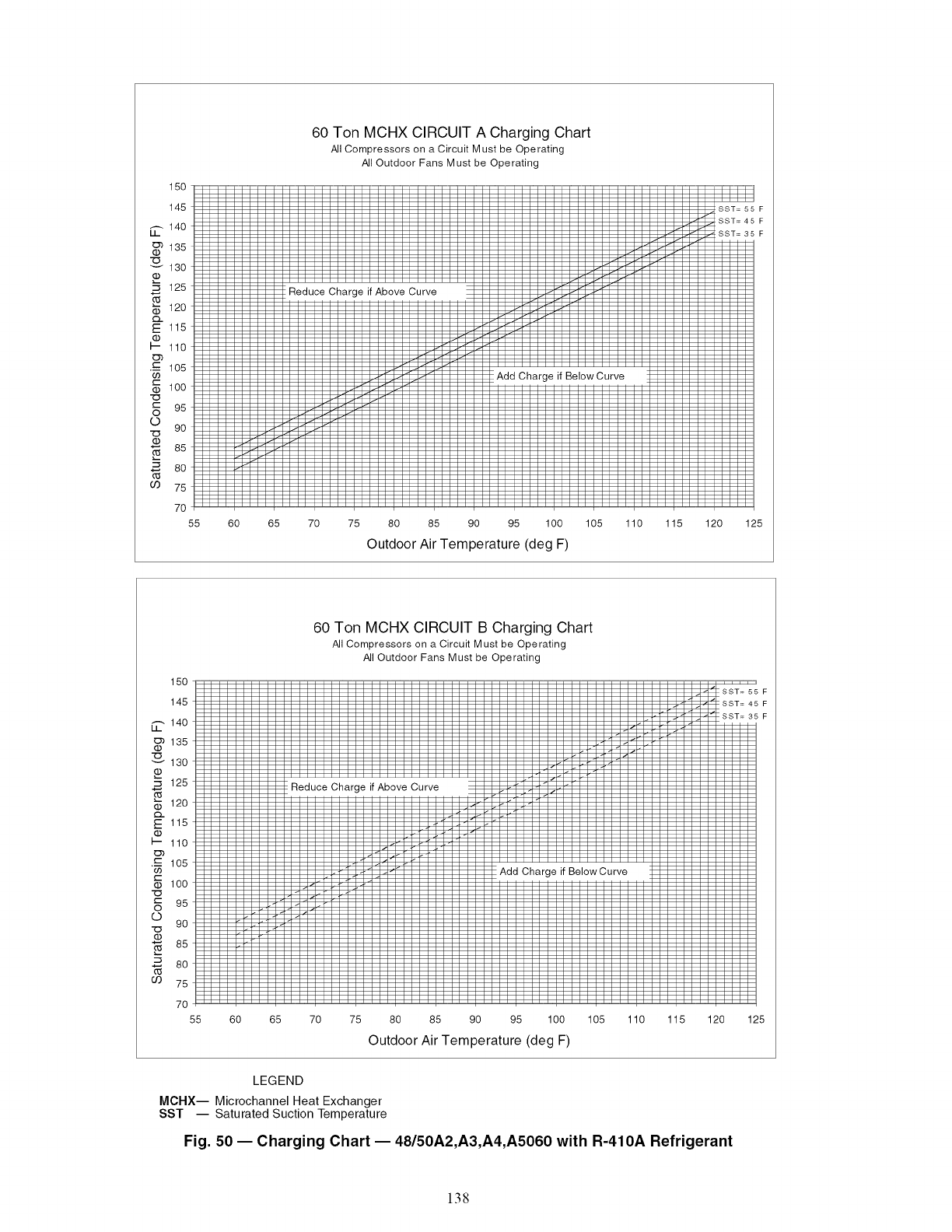
15o
145
140
135
130
03
125
120
Q..
E 115
03
I-- 110
Ob
._c 105
100
r-- 95
o
©9O
85
03
8O
75
7O
55 60
60 Ton MCHX CIRCUIT A Charging Chart
All Compressors on a Circuit Must be Operating
All Outdoor Fans Must be Operating
! Reduce Charge if Above Curve
Add Charge if BelowCurve
65 70 75 80 85 90 95 100 105 110 115 120
Outdoor Air Temperature (deg F)
F
F
F
125
15O
145
_-, 140
135
130
125
120
Q.
E 115
03
I-- 110
o3
_- 105
t--
03 lOO
t-
O
©
03
03
95
9O
85
8O
75
7O
55 60
60 Ton MCHX CIRCUIT B Charging Chart
All Compressors on a Circuit Must be Operating
All Outdoor Fans Must be Operating
Reduce Charge if Above Curve
Add Charge if BelowCurve
65 70 75 80 85 90 95 100 105 110 115 120
Outdoor Air Temperature (deg F)
F
F
F
125
LEGEND
MCHX-- Microchannel Heat Exchanger
SST -- Saturated Suction Temperature
Fig. 50- Charging Chart -- 48/50A2,A3,A4,AS060 with R-410A Refrigerant
138
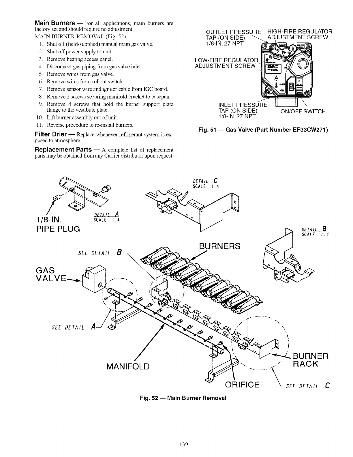
Main Burners- For all applications, main burners are
factory set and should require no adjusUnent.
MAIN BURNER REMOVAL (Fig. 52)
1. Shut off (field-supplied) manual main gas valve.
2. Shut offpower supply to unit.
3. Remove heating access panel.
4. Disconnect gas piping from gas valve inlet.
5. Remove wires from gas valve.
6. Remove wires from rollout switch.
7. Remove sensor wire and ignitor cable from IGC board.
8. Remove 2 screws securing manifold bracket to basepan.
9. Remove 4 screws that hold the burner support plate
flange to the vestibule plate.
10. Lift burner assembly out of unit.
11. Reverse procedure to re-install burners.
Filter Drier -- Replace whenever refrigerant system is ex-
posed to atmosphere.
Replacement Parts -- A complete list of replacement
parts may be obtained from any Carrier distributor upon request.
OUTLET PRESSURE HIGH-FIRE REGULATOR
TAP (ON SIDE) ADJUSTMENT SCREW
1/8-1N. 27 NPT
LOW-FIRE REGULATOR
ADJUSTMENT SCREW
INLET PRESSURE
TAP (ON SIDE)
1/8-1N.27 NPT ON/OFF SWITCH
Fig. 51 -- Gas Valve (Part Number EF33CW271)
1/8-1N. SCALE
PIPE PLUG
SEE DETA IL
GAS
VALV
SEE DETAIL
OETAIt C
SCALE t :4
A
1:4
BURNERS
\
\
MANIFOLD
\
\
i
t
BURNER
Fig. 52 -- Main Burner Removal
139
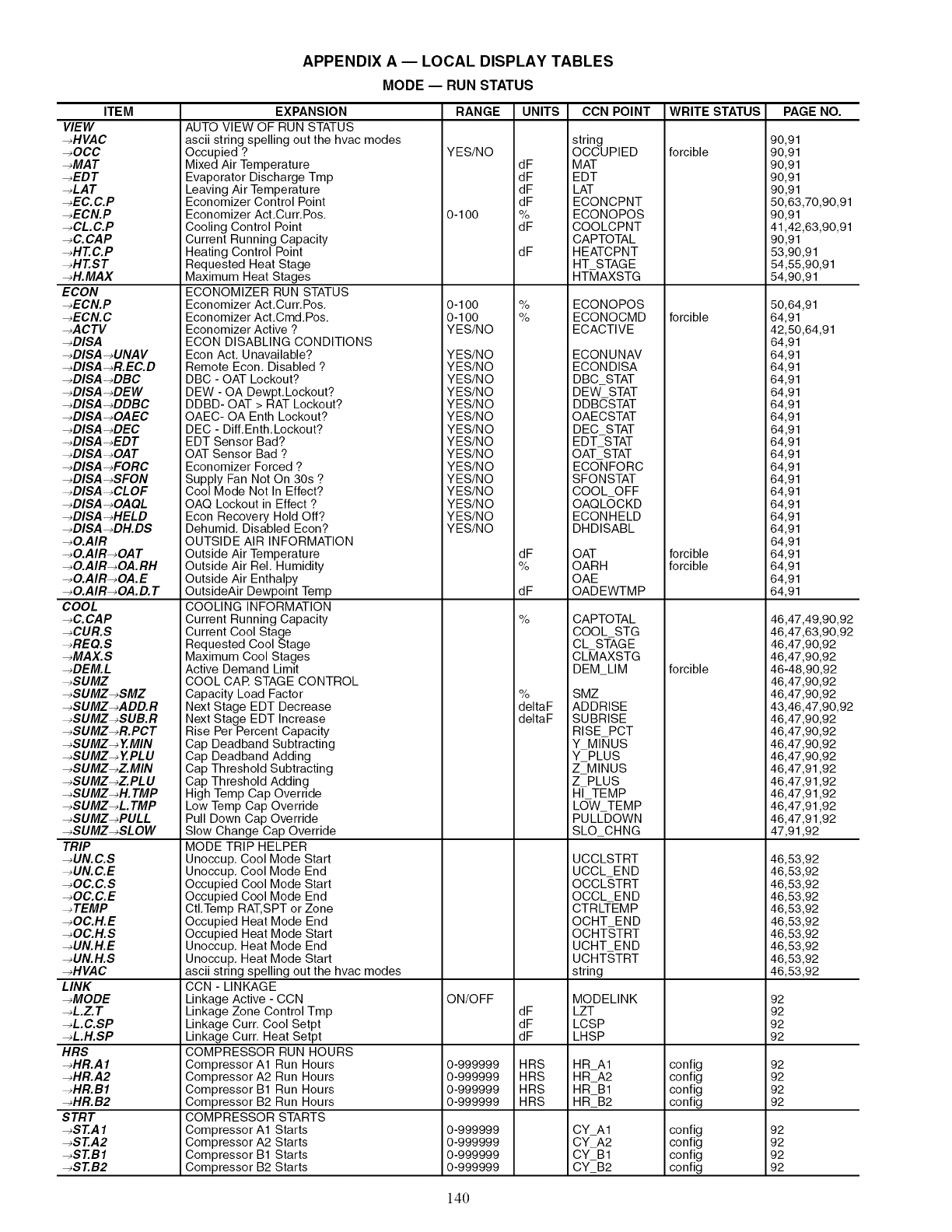
APPENDIX A -- LOCAL DISPLAY TABLES
MODE -- RUN STATUS
ITEM
VIEW
-_HVAC
-_OCC
-_MAT
-_EDT
-_LAT
-_EC. C.P
-_ECN.P
-_CL.C.P
-_C.CAP
-_HT.C.P
-_HT.ST
-_H.MAX
ECON
-_ECN.P
-_ECN.C
-_ACTV
-_DISA
-_DISA-_UNAV
-_DISA-_R.EC.D
-_DISA-_DBC
-_DISA-_DEW
-_DISA-_DDBC
-_DISA-_OAEC
-_DISA-_DEC
-_DISA-_EDT
-_DISA-_OA T
-_DISA-_FORC
-_DISA-_SFON
-_DISA-_CLOF
-_DISA-_OAQL
-_DISA-_HELD
-_DISA-_DH.DS
-_O.AIR
-_O.AIR-_OA T
-_O.AIR-_OA.RH
-_O.AIR-_OA.E
-_O.AIR-_OA.D. T
COOL
-_C.CAP
-_CUR.S
-_REQ.S
-_MAX.S
-_DEM.L
-_SUMZ
-_SUMZ-_SMZ
-_SUMZ-_ADD.R
-_SUMZ-_SUB.R
-_SUMZ-_R.PCT
-_SUMZ-_ Y.MIN
-_SUMZ-_ Y.PL U
-_SUMZ-_Z.MIN
-_SUMZ-_Z.PL U
-_SUMZ-_H. TMP
-_SUMZ-_L. TMP
-_SUMZ-_PULL
-_SUMZ-_SLOW
TRIP
-_UN.C.S
-_UN. C.E
-_OC.C.S
-_OC.C.E
-_TEMP
-_OC.H.E
-_OC.H.S
-_UN.H.E
-_UN.H.S
-_HVAC
LINK
-_MODE
-_L.Z. T
-_L.C.SP
-_L.H.SP
HRS
-_HR.A I
-_HR.A2
-_HR.BI
-_HR. B2
STRT
_ST.A 1
_ST.A2
-_ST.B1
-_ST.B2
EXPANSION
AUTO VIEW OF RUN STATUS
ascii string spelling out the hvac modes
Occupied ?
Mixed Air Temperature
Evaporator Discharge Tmp
Leaving Air Tempe ratu re
Economizer Control Point
Economizer Act.Curr.Pos.
Cooling Control Point
Current Running Capacity
Heating Control Point
Requested Heat Stage
Maximum Heat Stages
ECONOMIZER RUN STATUS
Economizer Act.Curr.Pos.
Economizer Act.Cmd.Pos.
Economizer Active ?
ECON DISABLING CONDITIONS
Econ Act. Unavailable?
Remote Econ. Disabled ?
DBC - OAT Lockout?
DEW - OA Dewpt.Lockout?
DDBD- OAT > RAT Lockout?
OAEC- OA Enth Lockout?
DEC - Diff.Enth.Lockout?
EDT Sensor Bad?
OAT Sensor Bad ?
Economizer Forced ?
Supply Fan Not On 30s ?
Cool Mode Not In Effect?
OAQ Lockout in Effect ?
Econ Recovery Hold Off?
Dehumid. Disabled Econ?
OUTSIDE AIR INFORMATION
Outside Air Temperature
Outside Air Rel. Humidity
Outside Air Enthalpy
OutsideAir Dewpoint Temp
COOLING INFORMATION
Current Running Capacity
Current Cool Stage
Requested Cool Stage
Maximum Cool Stages
Active Demand Limit
COOL CAR STAGE CONTROL
Capacity Load Factor
Next Stage EDT Decrease
Next Stage EDT Increase
Rise Per Percent Capacity
Cap Deadband Subtracting
Cap Deadband Adding
Cap Threshold Subtracting
Cap Threshold Adding
High Temp Cap Override
Low Temp Cap Override
Pull Down Cap Override
Slow Change Cap Override
MODE TRIP HELPER
Unoccup. Cool Mode Start
Unoccup. Cool Mode End
Occupied Cool Mode Start
Occupied Cool Mode End
CtI.Temp RAT,SPT or Zone
Occupied Heat Mode End
Occupied Heat Mode Start
Unoccup. Heat Mode End
Unoccup. Heat Mode Start
ascii string spelling out the hvac modes
CCN - LINKAGE
Linkage Active - CCN
Linkage Zone Control Tmp
Linkage Curr. Cool Setpt
Linkage Curr. Heat Setpt
COMPRESSOR RUN HOURS
Compressor A1 Run Hours
Compressor A2 Run Hours
Compressor B1 Run Hours
Compressor B2 Run Hours
COMPRESSOR STARTS
Compressor A1 Starts
Compressor A2 Starts
Compressor B1 Starts
Compressor B2 Starts
RANGE UNITS
YES/NO
0-1O0
0-1O0
0-1O0
YES/NO
YES/NO
YES/NO
YES/NO
YES/NO
YES/NO
YES/NO
YES/NO
YES/NO
YES/NO
YES/NO
YES/NO
YES/NO
YES/NO
YES/NO
YES/NO
ON/OFF
0-999999
0-999999
0-999999
0-999999
0-999999
0-999999
0-999999
0-999999
dF
dF
dF
dF
%
dF
dF
%
%
dF
%
dF
%
%
deltaF
deltaF
dF
dF
dF
HRS
HRS
HRS
HRS
CCN POINT
string
OCCUPIED
MAT
EDT
LAT
ECONCPNT
ECONOPOS
COOLCPNT
CAPTOTAL
HEATCPNT
HT STAGE
HT_IAXSTG
ECONOPOS
ECONOCMD
ECACTIVE
ECONUNAV
ECONDISA
DBC STAT
DEW- STAT
DDBCSTAT
OAECSTAT
DEC STAT
EDT STAT
OAT STAT
ECONFORC
SFONSTAT
COOL OFF
OAQLOCKD
ECONHELD
DHDISABL
OAT
OARH
OAE
OADEWTMP
CAPTOTAL
COOL STG
CL ST-AGE
CL_IAXSTG
DEM_LIM
SMZ
ADDRISE
SUBRISE
RISE PCT
Y MlhlUS
YPLUS
ZMINUS
Z PLUS
H/TEMP
LOW TEMP
PULLDOWN
SLO CHNG
UCCLSTRT
UCCL END
OCCLSTRT
OCCL END
CTRL-I=EMP
OCHT END
OCHT,STRT
UCHT END
UCHT,STRT
string
MODELINK
LZT
LCSP
LHSP
HRA1
HRA2
HRB1
HR_B2
CYA1
CYA2
CYB1
CY_B2
WRITE STATUS
forcible
forcible
forcible
forcible
forcible
config
config
config
config
config
config
config
config
PAGE NO.
90,91
90,91
90,91
90,91
90,91
50,63,70,90,91
90,91
41,42,63,90,91
90,91
53,90,91
54,55,90,91
54,90,91
50,64,91
64,91
42,50,64,91
64,91
64,91
64,91
64,91
64,91
64,91
64,91
64,91
64,91
64,91
64,91
64,91
64,91
64,91
64,91
64,91
64,91
64,91
64,91
64,91
64,91
46,47,49,90,92
46,47,63,90,92
46,47,90,92
46,47,90,92
46-48,90,92
46,47,90,92
46,47,90,92
43,46,47,90,92
46,47,90,92
46,47,90,92
46,47,90,92
46,47,90,92
46,47,91,92
46,47,91,92
46,47,91,92
46,47,91,92
46,47,91,92
47,91,92
46,53,92
46,53,92
46,53,92
46,53,92
46,53,92
46,53,92
46,53,92
46,53,92
46,53,92
46,53,92
92
92
92
92
92
92
92
92
92
92
92
92
140
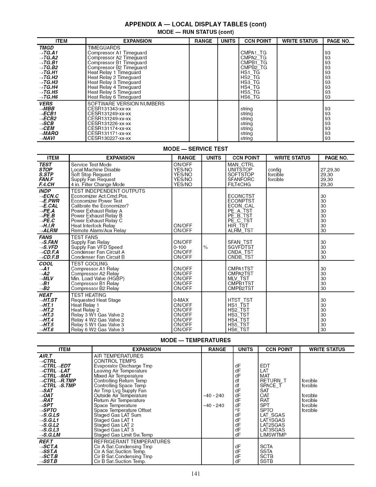
ITEM
TMGD
-_ TG.A 1
-_ TG.A2
-_TG.B1
-_ TG.B2
-_TG.H1
-_ TG.H2
-_ TG.H3
-_ TG.H4
-_ TG.H5
-_ TG.H6
VERS
-_MBB
-_ECB1
-_ECB2
-_SCB
-_CEM
-_MARQ
-_NA Vl
APPENDIX A -- LOCAL DISPLAY TABLES (cont)
MODE -- RUN STATUS (cont)
EXPANSION
TIMEGUARDS
Compressor A1 Timeguard
Compressor A2 Timeguard
Compressor B1 Timeguard
Compressor B2 Timeguard
Heat Relay 1 Timeguard
Heat Relay 2 Timeguard
Heat Relay 3 Timeguard
Heat Relay 4 Timeguard
Heat Relay 5 Timeguard
Heat Relay 6 Timeguard
SOFTWARE VERSION NUMBERS
CESR131343-xx-xx
CESR131249-xx-xx
CESR131249-xx-xx
CESR131226-xx-xx
CESR131174-xx-xx
CESR131171 -xx-xx
CESR130227-xx-xx
RANGE UNITS CCN POINT
CMPA1 TG
CMPA2 TG
CMPB1 TG
CMPB2 TG
HS1TC_
HS2TG
HS3TG
HS4TG
HS5TG
HS6TG
string
string
string
string
string
string
string
WRITE STATUS PAGE NO.
93
93
93
93
93
93
93
93
93
93
93
93
93
93
93
93
93
ITEM
TEST
STOP
S.STP
FAN.F
F.4.CH
INDP
-_ECN. C
-_E.PWR
-_E.CAL
-_PE.A
-_PE.B
-_PE. C
-_H.LR
-_ALRM
FANS
-_S.FAN
-_S. VFD
-_CD.F.A
-_CD.F.B
COOL
-_A 1
-_A2
-_MLV
-_B1
-_B2
HEAT
-_HT.ST
-_HT. 1
-_HT.2
-_HT.3
-_HT.4
-_HT.5
-_HT.6
MODE -- SERVICE TEST
EXPANSION
Service Test Mode
Local Machine Disable
Soft Stop Request
Supply Fan Request
4 in. Filter Change Mode
TEST INDEPENDENT OUTPUTS
Economizer Act.Cmd.Pos.
Economizer Power Test
Calibrate the Economizer?
Power Exhaust Relay A
Power Exhaust Relay B
Power Exhaust Relay C
Heat Interlock Relay
Remote Alarm/Aux Relay
TEST FANS
Supply Fan Relay
Supply Fan VFD Speed
Condenser Fan Circuit A
Condenser Fan Circuit B
TEST COOLING
Compressor A1 Relay
Compressor A2 Relay
Min. Load Valve (HGBP)
Compressor B1 Relay
Compressor B2 Relay
TEST HEATING
Requested Heat Stage
Heat Relay 1
Heat Relay 2
Relay 3 W1 Gas Valve 2
Relay 4 W2 Gas Valve 2
Relay 5 W1 Gas Valve 3
Relay 6 W2 Gas Valve 3
RANGE
ON/OFF
YES/NO
YES/NO
YES/NO
YES/NO
ON/OFF
ON/OFF
ON/OFF
0-100
ON/OFF
ON/OFF
ON/OFF
ON/OFF
ON/OFF
ON/OFF
ON/OFF
O-MAX
ON/OFF
ON/OFF
ON/OFF
ON/OFF
ON/OFF
ON/OFF
UNITS
%
CCN POINT
MAN CTRL
UNIT-STOP
SOFTSTOP
SFANFORC
FILT4CHG
ECONCTST
ECONPTST
ECON CAL
PE A =I-ST
PE B TST
PE C TST
HIR TST
ALR-M TST
SFAN TST
SGVF-DTST
CNDA TST
CNDB_TST
CM PAl TST
CMPA2TST
MLV TST
CMPB1TST
CMPB2TST
HTST TST
HS1TST
HS2 TST
HS3_TST
HS4_TST
HS5 TST
HS6 TST
WRITE STATUS
config
forcible
forcible
PAGE NO.
27,29,30
29,30
29,30
29,30
30
30
30
30
30
30
30
30
3O
3O
3O
3O
30
30
30
30
30
30
30
30
30
30
30
30
ITEM
AIR.T
-_CTRL
-_CTRL-_EDT
-_CTRL-_LAT
-_CTRL-_MAT
-_CTRL-_R. TMP
-_CTRL-_S. TMP
-_SAT
-_OA T
-_RAT
-_SPT
-_SPTO
-_S.G.LS
-_S.G.L1
-_S.G.L2
-_S.G.L3
-_S.G.LM
REF. T
-_SCT.A
-_SST.A
-_SCT.B
-_SST.B
MODE -- TEMPERATURES
EXPANSION
AIR TEMPERATURES
CONTROL TEMPS
Evaporator Discharge Tmp
Leaving Air Tempe ratu re
Mixed Air Tempe ratu re
Controlling Return Temp
Controlling Space Temp
Air Tmp Lvg Supply Fan
Outside Air Temperature
Return Air Temperature
Space Temperatu re
Space Temperatu re Offset
Staged Gas LAT Sum
Staged Gas LAT 1
Staged Gas LAT 2
Staged Gas LAT 3
Staged Gas Limit Sw.Temp
REFRIGERANT TEMPERATURES
Cir A Sat.Condensing Tmp
Cir A Sat.Suction Temp.
Cir B Sat.Condensing Tmp
Cir B Sat.Suction Temp.
RANGE
-40-240
-40-240
UNITS
dF
dF
dF
df
df
dF
dF
dF
dF
^F
dF
dF
dF
dF
dF
dF
dF
dF
dF
CCN POINT
EDT
LAT
MAT
RETURN T
SPACE_T-
SAT
OAT
RAT
SPT
SPTO
LAT SGAS
LAT1-SGAS
LAT2SGAS
LAT3SGAS
LIMSWTMP
SCTA
SSTA
SCTB
SSTB
WRITE STATUS
forcible
forcible
forcible
forcible
forcible
forcible
141
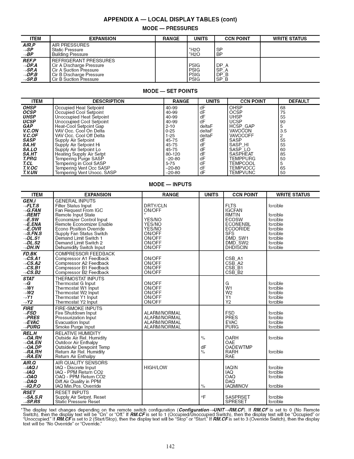
APPENDIX A -- LOCAL DISPLAY TABLES (cont)
MODE -- PRESSURES
ITEM EXPANSION RANGE UNITS CCN POINT WRITE STATUS
AIR.P AIR PRESSURES
-*SP Static Pressure "H20 SP
-*BP Building Pressure "H20 BP
REF.P REFRIGERANT PRESSURES
-*DP.A Cir A Discharge Pressure PSIG DPA
-*SP.A Cir A Suction Pressure PSIG SPA
-,DAB Cir B Discharge Pressure PSIG DPB
-,SP.B Cir B Suction Pressure PSIG SPB
MODE -- SET POINTS
DEFAULTITEM
OHSP
OCSP
UHSP
UCSP
GAP
VC.ON
VC.OF
SASP
SA.HI
SA.LO
SA.HT
T.PRG
T.CL
T.VOC
T.VUN
DESCRIPTION
Occupied Heat Setpoint
Occupied Cool Setpoint
Unoccupied Heat Setpoint
Unoccupied Cool Setpoint
Heat-Cool Setpoint Gap
VAV Occ. Cool On Delta
VAV Occ. Cool Off Delta
Supply Air Setpoint
Supply Air Setpoint Hi
Supply Air Setpoint Lo
Heating Supply Air Setpt
Tempering Purge SASP
Tempering in Cool SASP
Tempering Vent Occ SASP
Tempering Vent Unocc. SASP
RANGE
40 -99
40 -99
40 -99
40 -99
2-10
0-25
1-25
45-75
45 -75
45 -75
80-120
-20-80
5-75
-20-80
-20-80
UNITS
dF
dF
dF
dF
deltaF
deltaF
deltaF
dF
dF
dF
dF
dF
dF
dF
dF
CCN POINT
OHSP
OCSP
UHSP
UCSP
HCSP GAP
VAVOCON
VAVOCOFF
SASP
SASP HI
SASP LO
SASPHEAT
TEMPPURG
TEMPCOOL
TEMPVOCC
TEMPVUNC
68
75
55
90
5
3.5
2
55
55
60
85
50
5
65
50
MODE -- INPUTS
ITEM
GEN.I
-,FLT.S
-,G.FAN
-,REMT
-,E.SW
-, E. ENA
-,E.OVR
-,S.FN.S
-,DL.S1
-,DL.S2
-,DH.IN
FD.BK
-,CS.A 1
-,CS.A2
-,CS.B1
-,CS.B2
STAT
-,G
-,W1
-, W2
-,Y1
-, Y2
FIRE
-,FSD
-,PRES
-,EVAC
-,PURG
RELH
-,OA.RH
-,OA.EN
-,OA.DP
-,RA.RH
-,RA.EN
AIR.Q
-,IAQ.I
-,IAQ
-,OAQ
-,DAQ
-,IQ.R O
RSET
-,SA.S.R
-,SP.RS
EXPANSION
GENERAL INPUTS
Filter Status Input
Fan Request From IGC
Remote Input State
Economizer Control Input
Remote Economizer Enable
Econo Position Override
Supply Fan Status Switch
Demand Limit Switch 1
Demand Limit Switch 2
Dehumidify Switch Input
COMPRESSOR FEEDBACK
Compressor A1 Feedback
Compressor A2 Feedback
Compressor B1 Feedback
Compressor B2 Feedback
THERMOSTAT INPUTS
Thermostat G Input
Thermostat W1 Input
Thermostat W2 Input
Thermostat Y1 Input
Thermostat Y2 Input
FIRE-SMOKE INPUTS
Fire Shutdown Input
Pressurization Input
Evacuation Input
Smoke Purge Input
RELATIVE HUMIDITY
Outside Air Rel. Humidity
Outdoor Air Enthalpy
OutsideAir Dewpoint Temp
Return Air Rel. Humidity
Return Air Enthalpy
AIR QUALITY SENSORS
IAQ - Discrete Input
IAQ - PPM Return C02
OAQ - PPM Return C02
Diff.Air Quality in PPM
IAQ Min.Pos. Override
RESET INPUTS
Supply Air Setpnt. Reset
Static Pressure Reset
RANGE
DRTY/C LN
ON/OFF
YES/NO
YES/NO
YES/NO
ON/OFF
ON/OFF
ON/OFF
ON/OFF
ON/OFF
ON/OFF
ON/OFF
ON/OFF
ON/OFF
ON/OFF
ON/OFF
ON/OFF
ON/OFF
ALARM/NORMAL
ALARM/NORMAL
ALARM/NORMAL
ALARM/NORMAL
HIGH/LOW
UNITS
%
dF
%
%
AF
CCN POINT
FLTS
IGCFAN
RMTIN
ECOSW
ECONENBL
ECOORIDE
SFS
DMD SWl
DMD SW2
DHD/SCIN
CSBA1
CSBA2
CSBB1
CSB_B2
G
W1
W2
Y1
Y2
FSD
PRES
EVAC
PURG
OARH
OAE
OADEWTMP
RARH
RAE
IAQIN
IAQ
OAQ
DAQ
IAQMINOV
SASPRSET
SPRESET
WRITE STATUS
forcible
forcible
forcible
forcible
forcible
forcible
forcible
forcible
forcible
forcible
forcible
forcible
forcible
forcible
forcible
forcible
forcible
forcible
forcible
forcible
forcible
forcible
forcible
forcible
forcible
forcible
*The display text changes depending on the remote switch configuration (Configuration-_UNIT-_RM.CF). If RM.CF is set to 0 (No Remote
Switch), then the display text will be "On" or "Off." If RM.CF is set to 1 (Occupied/Unoccupied Switch), then the display text will be "Occupied" or
"Unoccupied." If RM.CFis set to 2 (Start/Stop), then the display text will be "Stop" or "Start." If RM.CFis set to 3 (Override Switch), then the display
text will be "No Override" or "Override."
142
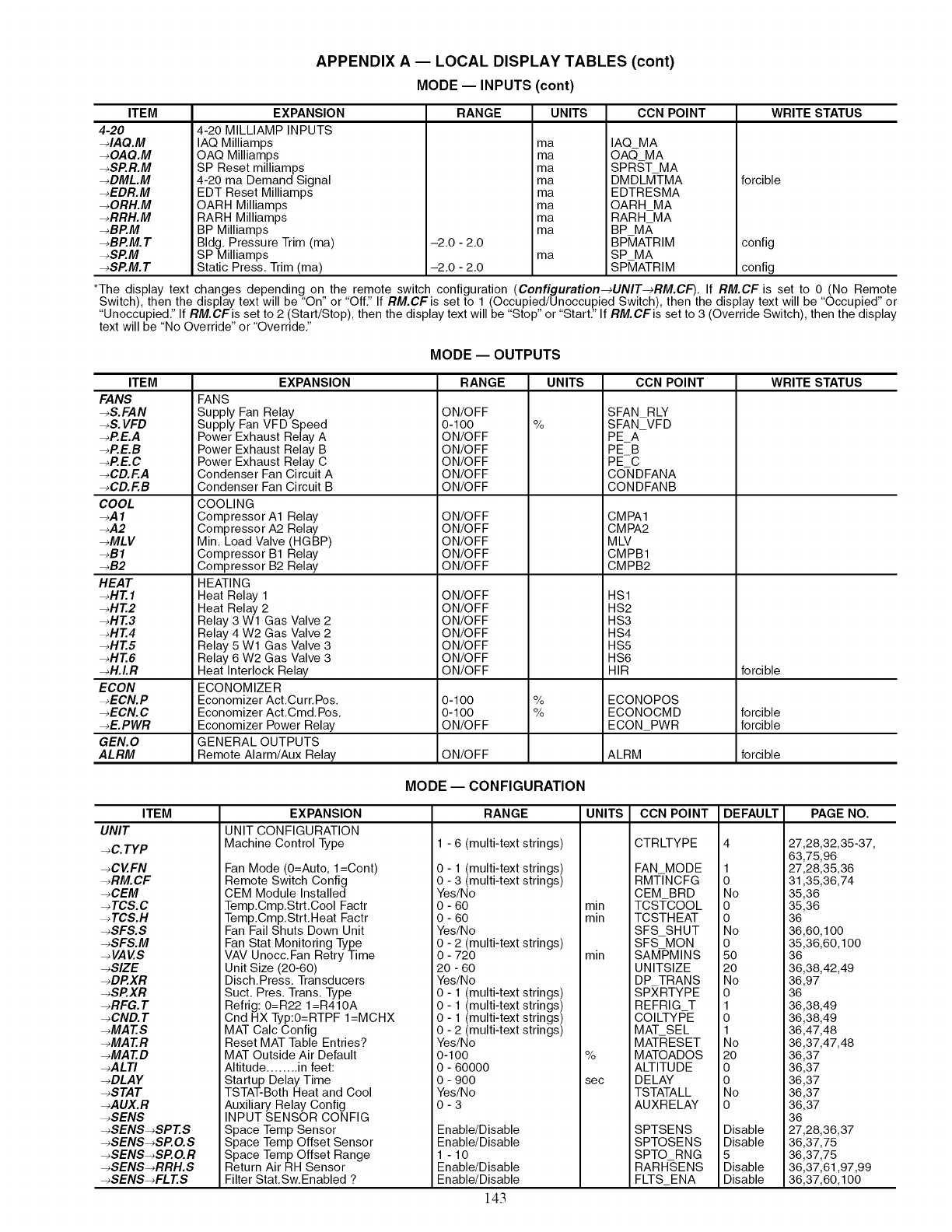
APPENDIX A -- LOCAL DISPLAY TABLES (cont)
MODE-- INPUTS (cont)
ITEM
4-20
-dAQ.M
-_OAQ.M
-_SP.R.M
-_DML.M
-_EDR. M
-_ORH.M
-_RRH.M
-_BP.M
-_BP.M. T
-_SP.M
-_SP.M. T
EXPANSION
4-20 MILLIAMP INPUTS
IAQ Milliamps
OAQ Milliamps
SP Reset milliamps
4-20 ma Demand Signal
EDT Reset Milliamps
OARH Milliamps
RARH Milliamps
BP Milliamps
Bldg. Pressure Trim (ma)
SP Milliamps
Static Press. Trim (ma)
RANGE
-2.0 - 2.0
-2.0 - 2.0
UNITS
ma
ma
ma
ma
ma
ma
ma
ma
ma
CCN POINT
IAQ MA
OA_MA
SPRST MA
DMDLMTMA
EDTRESMA
OARH MA
RARH MA
BP M,_,
BP_4ATRIM
SP MA
SP_4ATRIM
WRITE STATUS
forcible
config
config
*The display text changes depending on the remote switch configuration (Configuration-_UNIT-_RM.CF). If RM.CF is set to 0 (No Remote
Switch), then the display text will be "On" or "Off." If RM.CF is set to 1 (Occupied/Unoccupied Switch), then the display text will be "Occupied" or
"Unoccupied." If RM.CFis set to 2 (Start/Stop), then the display text will be "Stop" or "Start." If RM.CFis set to 3 (Override Switch), then the display
text will be "No Override" or "Override."
MODE -- OUTPUTS
ITEM
FANS
-_S.FAN
-_S. VFD
-_P.E.A
-_P.E.B
-_P.E.C
-_CD.F.A
-_CD.F.B
COOL
-_A 1
-_A2
-_MLV
-_B1
-_B2
HEAT
-_HT. 1
-_HT.2
-_HT.3
-_HT.4
-_HT.5
-_HT.6
-_H.LR
ECON
-_ECN.P
-_ECN. C
-_E.PWR
GEN. 0
ALRM
EXPANSION
FANS
Supply Fan Relay
Supply Fan VFD Speed
Power Exhaust Relay A
Power Exhaust Relay B
Power Exhaust Relay C
Condenser Fan Circuit A
Condenser Fan Circuit B
COOLING
Compressor A1 Relay
Compressor A2 Relay
Min. Load Valve (HGBP)
Compressor B1 Relay
Compressor B2 Relay
HEATING
Heat Relay 1
Heat Relay 2
Relay 3 Wl Gas Valve 2
Relay 4 W2 Gas Valve 2
Relay 5 Wl Gas Valve 3
Relay 6 W2 Gas Valve 3
Heat Interlock Relay
ECONOMIZER
Economizer Act.Curr.Pos.
Economizer Act.Cmd.Pos.
Economizer Power Relay
GENERAL OUTPUTS
Remote Alarm/Aux Relay
RANGE UNITS CCN POINT WRITE STATUS
ON/OFF
01100
ON/OFF
ON/OFF
ON/OFF
ON/OFF
ON/OFF
ON/OFF
ON/OFF
ON/OFF
ON/OFF
ON/OFF
ON/OFF
ON/OFF
ON/OFF
ON/OFF
ON/OFF
ON/OFF
ON/OFF
0-100
%
%
SFAN RLY
SFAN VFD
PEA
PEB
PE C
CO-NDFANA
CONDFANB
CMPA1
CMPA2
MLV
CMPB1
CMPB2
HS1
HS2
HS3
HS4
HS5
HS6
HIR
ECONOPOS
0-100
ON/OFF
ON/OFF
%ECONOCMD
ECONPWR
ALRM
forcible
forcible
forcible
forcible
MODE -- CONFIGURATION
ITEM
UNIT
-_C. TYP
-_CVFN
-_RM. CF
-_CEM
-_TCS.C
-_TCS.H
-_SFS.S
-_SFS.M
-_ VAV.S
-_SlZE
-_DP.XR
-_SP.XR
-_RFG. T
-_CND. T
-_MAT.S
-_MAT.R
-_MAT.D
-_ALTI
-_DLAY
-_STAT
-_AUX.R
-_SENS
-_SENS-_SPT.S
-_SENS-_SP. O.S
-_SENS-_SP. O.R
-_SENS-_RRH.S
-_SENS-_FL T.S
EXPANSION
UNIT CONFIGURATION
Machine Control Type
Fan Mode (O=Auto, l=Cont)
Remote Switch Config
CEM Module Installed
Temp.Cmp.Strt.Cool Factr
Temp.Cmp.Strt.Heat Factr
Fan Fail Shuts Down Unit
Fan Stat Monitoring Type
VAV Unocc.Fan Retry Time
Unit Size (20-60)
Disch.Press. Transducers
Suct. Pres. Trans. Type
Refrig: 0=R22 1=R410A
Cnd HX Typ:O=RTPF I=MCHX
MAT Calc Config
Reset MAT Table Entries?
MAT Outside Air Default
Altitude ........ in feet:
Startup Delay Time
TSTAT-Both Heat and Cool
Auxiliary Relay Config
INPUT SENSOR CONFIG
Space Temp Sensor
Space Temp Offset Sensor
Space Temp Offset Range
Return Air RH Sensor
Filter Stat.Sw.Enabled ?
RANGE
1 - 6 (multi-text strings)
0 - 1 (multi-text strings)
0 - 3 (multi-text strings)
Yes/No
0 - 60 min
0 - 60 min
Yes/No
0 - 2 (multi-text strings)
0 - 720 min
20 - 60
Yes/No
0 - 1 (multi-text strings)
0 - 1 (multi-text strings)
0 - 1 (multi-text strings)
0 - 2 (multi-text strings)
Yes/No
0-100 %
0 - 60000
0 - 900 sec
Yes/No
0-3
Enable/Disable
Enable/Disable
1 -10
Enable/Disable
Enable/Disable
143
UNITS CCN POINT
CTRLTYPE
FAN MODE
RMT/NCFG
CEM BRD
TCS-I=COOL
TCSTHEAT
SFS SHUT
SFS MON
SAMPMINS
UNITSIZE
DP TRANS
SPXRTYPE
REFRIG T
COILTYPE
MAT SEL
MATRESET
MATOADOS
ALTITUDE
DELAY
TSTATALL
AUXRELAY
SPTSENS
SPTOSENS
SPTO RNG
RARH-SENS
FLTS_ENA
DEFAULT
1
o
No
0
0
No
0
5O
2O
No
0
1
0
1
No
2O
0
0
No
0
Disable
Disable
5
Disable
Disable
PAGE NO.
27,28,32,35-37,
63,75,96
27,28,35,36
31,35,36,74
35,36
35,36
36
36,60,1 O0
35,36,60,100
36
36,38,42,49
36,97
36
36,38,49
36,38,49
36,47,48
36,37,47,48
36,37
36,37
36,37
36,37
36,37
36
27,28,36,37
36,37,75
36,37,75
36,37,61,97,99
36,37,60,100
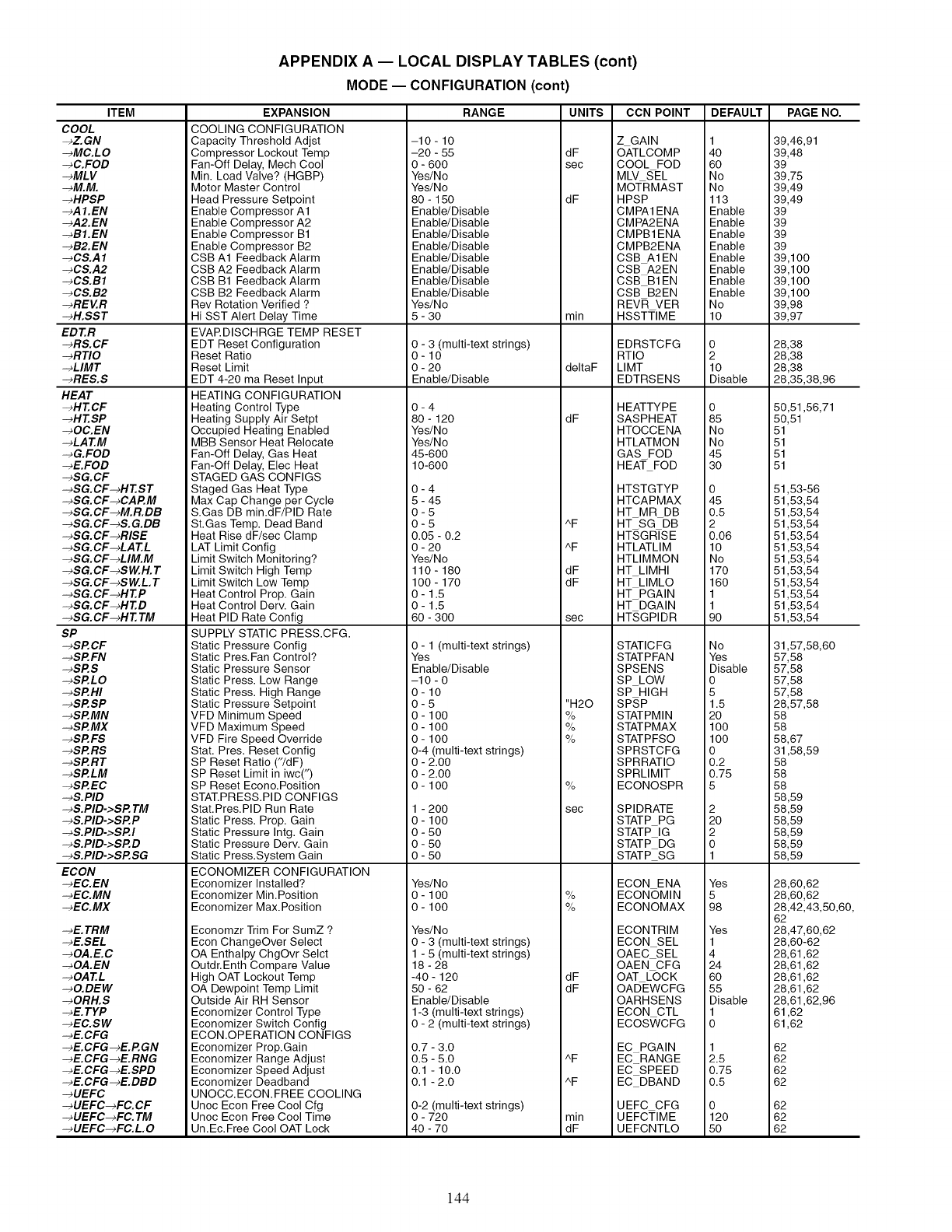
ITEM
COOL
-_Z. GN
-_MC.LO
-_C.FOD
-_MLV
-_M.M.
-_HPSP
-_A1.EN
-_A2.EN
-_B1.EN
-_B2.EN
-_CS.A 1
-_CS.A2
-_CS.B1
-_CS.B2
-_REVR
-_H.SST
EDT.R
-_RS.CF
-_RTIO
-_LIMT
-_RES.S
HEAT
-_HT.CF
-_HT.SP
-_OC.EN
-_LAT.M
-_G.FOD
-_E.FOD
-_SG.CF
-_SG.CF-_HT.ST
-_SG.CF-_CAP.M
-_SG.CF-_M.R.DB
-_SG.CF-_S.G.DB
-_SG.CF-_RISE
-_SG.CF-_LAT.L
-_SG.CF-_LIM.M
-_SG.CF-_SI/V.H. T
-_SG.CF-_SW.L. T
-_SG.CF-_HT.P
-_SG.CF-_HT.D
-_SG.CF-_HT. TM
SP
-_SP.CF
-_SP.FN
-_SP.S
-_SP.LO
-_SP.HI
-_SP.SP
-_SP.MN
-_SP.MX
-_SP.FS
-_SP.RS
-_SP.RT
-_SP.LM
-_SP.EC
-_S.PID
-_S.PID->SP. TM
-_S.PID->SP.P
-_S.PID->SP.I
-_S.PID->SP.D
-_S.PID->SP.SG
ECON
-_EC.EN
-_EC.MN
-_EC.MX
-_E. TRM
-_E.SEL
-_OA.E.C
-_OA.EN
-_OAT.L
-_O.DEW
-_ORH.S
-_E. TYP
-_EC.SW
-_E.CFG
-_E.CFG-_E.P.GN
-_E.CFG -_E. RNG
-_E.CFG -_E. SPD
-_E.CFG-_E.DBD
-_UEFC
-_UEFC-_FC. CF
-_UEFC-_FC. TM
-_UEFC-_FC. L. 0
APPENDIX A -- LOCAL DISPLAY TABLES (cont)
MODE -- CONFIGURATION (cont)
EXPANSION
COOLING CONFIGURATION
Capacity Threshold Adjst
Compressor Lockout Temp
Fan-Off Delay, Mech Cool
Min. Load Valve? (HGBP)
Motor Master Control
Head Pressure Setpoint
Enable Compressor A1
Enable Compressor A2
Enable Compressor B1
Enable Compressor B2
CSB A1 Feedback Alarm
CSB A2 Feedback Alarm
CSB B1 Feedback Alarm
CSB B2 Feedback Alarm
Rev Rotation Verified ?
Hi SST Alert Delay Time
EVAP.DISCHRGE TEMP RESET
EDT Reset Configuration
Reset Ratio
Reset Limit
EDT 4-20 ma Reset Input
HEATING CONFIGURATION
Heating Control Type
Heating Supply Air Setpt
Occupied Heating Enabled
MBB Sensor Heat Relocate
Fan-Off Delay, Gas Heat
Fan-Off Delay, Elec Heat
STAGED GAS CONFIGS
Staged Gas Heat Type
Max Cap Change per Cycle
S.Gas DB min.dF/PID Rate
St.Gas Temp. Dead Band
Heat Rise dF/sec Clamp
LAT Limit Config
Limit Switch Monitoring?
Limit Switch High Temp
Limit Switch Low Temp
Heat Control Prop. Gain
Heat Control Defy. Gain
Heat PID Rate Config
SUPPLY STATIC PRESS.CFG.
Static Pressure Config
Static Pres.Fan Control?
Static Pressure Sensor
Static Press. Low Range
Static Press. High Range
Static Pressure Setpoint
VFD Minimum Speed
VFD Maximum Speed
VFD Fire Speed Override
Stat. Pres. Reset Config
SP Reset Ratio ("/dF)
SP Reset Limit in iwcC)
SP Reset Econo.Position
STAT.PRESS.PID CONFIGS
Stat.Pres.PID Run Rate
Static Press. Prop. Gain
Static Pressure Intg. Gain
Static Pressure Defy. Gain
Static Press.System Gain
ECONOMIZER CONFIGURATION
Economizer Installed?
Economizer Min. Position
Economizer Max. Position
Economzr Trim For SumZ ?
Econ ChangeOver Select
OA Enthalpy ChgOvr Selct
Outdr.Enth Compare Value
High OAT Lockout Temp
OA Dewpoint Temp Limit
Outside Air RH Sensor
Economizer Control Type
Economizer Switch Config
ECON.OPERATION CONFIGS
Economizer Prop.Gain
Economizer Range Adjust
Economizer Speed Adjust
Economizer Deadband
UNOCC.ECON.FREE COOLING
Unoc Econ Free Cool Cfg
Unoc Econ Free Cool Time
Un.Ec.Free Cool OAT Lock
RANGE UNITS
-10 - 10
-20 - 55
0 - 600
Yes/No
Yes/No
80 - 150
Enable/Disable
Enable/Disable
Enable/Disable
Enable/Disable
Enable/Disable
Enable/Disable
Enable/Disable
Enable/Disable
Yes/No
5 - 30
0 - 3 (multi-text strings)
0-10
0 - 20
Enable/Disable
0-4
80- 120
Yes/No
Yes/No
45-600
10-600
0-4
5 - 45
0-5
0-5
0.05 - 0.2
0 - 20
Yes/No
110 - 180
100 - 170
0- 1.5
0- 1.5
60 - 300
0 - 1 (multi-text strings)
Yes
Enable/Disable
-10 - 0
0-10
0-5
0 - 100
0 - 100
0 - 100
0-4 (multi-text strings)
0 - 2.00
0 - 2.00
0 - 100
1 - 200
0 - 100
0 - 50
0 - 50
0 - 50
Yes/No
0 - 100
0 - 100
Yes/No
0 - 3 (multi-text strings)
1 - 5 (multi-text strings)
18 - 28
-40 - 120
50 - 62
Enable/Disable
1-3 (multi-text strings)
0 - 2 (multi-text strings)
0.7 - 3.0
0.5 - 5.0
0.1 - 10.0
0.1 -2.0
0-2 (multi-text strings)
0 - 720
40 - 70
dF
sec
dF
min
deltaF
dF
AF
AF
dF
dF
"H20
%
%
%
%
sec
%
%
dF
dF
A F
A F
min
dF
CCN POINT
Z GAIN
OATLCOMP
COOL FOD
MLV SEL
MOTRMAST
HPSP
CMPA1 ENA
CMPA2ENA
CMPB1ENA
CMPB2ENA
CSB_A1EN
CSB_A2EN
CSB_B1EN
CSB B2EN
REVR VER
HSST_ME
EDRSTCFG
RTIO
LIMT
EDTRSENS
HEATTYPE
SASPHEAT
HTOCCENA
HTLATMON
GAS FOD
HEAT FOB
HTSTGTYP
HTCAPMAX
HT MR DB
HT SG DB
HTSGRISE
HTLATLIM
HTLIMMON
HT_LIMHI
HT_LIMLO
HT_PGAIN
HT DGAIN
HTSGPIDR
STATICFG
STATPFAN
SPSENS
SP_LOW
SP HIGH
SPSP
STATPMIN
STATPMAX
STATPFSO
SPRSTCFG
SPRRATIO
SPRLIMIT
ECONOSPR
SPIDRATE
STATP_PG
STATP_IG
STATP_DG
STATP SG
ECON ENA
ECONOMIN
ECONOMAX
ECONTRIM
ECON_SEL
OAECSEL
OAEN CFG
OAT LOCK
OADEWCFG
OARHSENS
ECON CTL
ECOS_A/CFG
EC_PGAIN
EC_RANGE
EC_SPEED
EC DBAND
UEFC CFG
UEFCTIME
UEFCNTLO
DEFAULT
1
40
60
No
No
113
Enable
Enable
Enable
Enable
Enable
Enable
Enable
Enable
No
10
0
2
10
Disable
0
85
No
No
45
3O
0
45
0.5
2
0.06
10
No
170
160
1
1
9O
No
Yes
Disable
0
5
1.5
2O
100
100
0
0.2
0.75
5
2
2O
2
0
1
Yes
5
98
Yes
1
4
24
6O
55
Disable
1
0
1
2.5
0.75
0.5
0
120
5O
PAGE NO.
39,46,91
39,48
39
39,75
39,49
39,49
39
39
39
39
39,100
39,100
39,100
39,100
39,98
39,97
28,38
28,38
28,38
28,35,38,96
50,51,56,71
50,51
51
51
51
51
51,53-56
51,53,54
51,53,54
51,53,54
51,53,54
51,53,54
51,53,54
51,53,54
51,53,54
51,53,54
51,53,54
51,53,54
31,57,58,60
57,58
57,58
57,58
57,58
28,57,58
58
58
58,67
31,58,59
58
58
58
58,59
58,59
58,59
58,59
58,59
58,59
28,60,62
28,60,62
28,42,43,50,60,
62
28,47,60,62
28,60-62
28,61,62
28,61,62
28,61,62
28,61,62
28,61,62,96
61,62
61,62
62
62
62
62
62
62
62
144
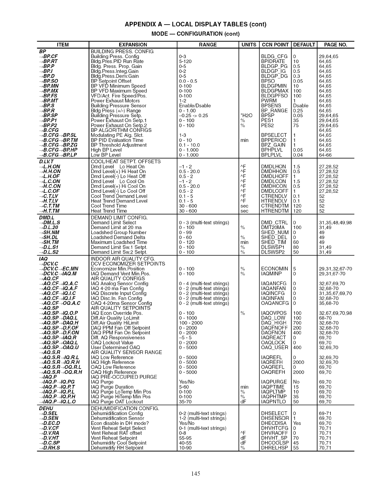
ITEM
BP
-_BP.CF
-_BP.RT
-_BP.P
-_BP.I
_BP.D
-_BP.SO
_BP.MN
_BP.MX
_BP.FS
_BP.MT
-_BP.S
-_BP.R
-_BP.SP
-_BP.P1
-_BP.P2
-_B. CFG
-_B.CFG-_BP.SL
-_B.CFG-_BP. TM
-_B.CFG-_BP.ZG
-_B.CFG-_BP.HP
-_B.CFG-_BP.LP
D.LVT
-_L.H.ON
-_H.H.ON
-_L.H.OF
-_L.C.ON
-_H.C.ON
-_L.C.OF
-_C. T.LV
-_H. T.LV
-_C. T.TM
-_H. T.TM
DMD.L
-_DM.L.S
-_D.L.20
-_SH. NM
-_SH.DL
-_SH. TM
-_D.L.Sl
-_D.L.S2
IAQ
-_DCVC
-_DCVC-_EC.MN
-_DCV C-4AQ.M
-_AQ.CF
-_A Q.CF-dQ.A. C
-_AQ.CF-dQ.A.F
-_AQ.CF-dQ.L C
-_AQ.CF-dQ.LF
-_AQ.CF-_OQ.A.C
-_AQ.SP
-_A Q.SP-dQ. O.P
-_AQ.SP-_DAQ.L
-_AQ.SP-_DAQ.H
-_AQ.SP-_D.F. OF
-_AQ.SP-_D.F. ON
-_AQ.SP-dAQ.R
-_AQ.SP-_OAQ.L
-_AQ.SP-_OAQ. U
-_AQ.S.R
-_AQ.S.R-dQ.R.L
-_AQ.S.R-dQ.R.H
-_AQ.S.R-_OQ.R.L
-_AQ.S.R-_OQ.R.H
-dAQ.P
-dAQ.P-dQ.PG
-dAQ.P-dQ.P. T
-dAQ.P-dQ.P.L
-dAQ.P-dQ.P.H
-_IA Q.P-_IQ. L 0
DEHU
-_D.SEL
-_D.SEN
-_D.EC.D
-_D. VCF
-_D. V RA
-_D. V HT
-_D.C.SP
-_D.RH.S
APPENDIX A -- LOCAL DISPLAY TABLES (cont)
MODE -- CONFIGURATION (cont)
EXPANSION
BUILDING PRESS, CONFIG
Building Press, Config
Bldg.Pres.PID Run Rate
Bldg. Press, Prop, Gain
Bldg.Press.lnteg.Gain
Bldg.Press.Deriv.Gain
BP Setpoint Offset
BP VFD Minimum Speed
BP VFD Maximum Speed
VFD/Act. Fire Speed/Pos.
Power Exhaust Motors
Building Pressure Sensor
Bldg Press (+/-) Range
Building Pressure Setp.
Power Exhaust On Setp.1
Power Exhaust On Setp.2
BP ALGORITHM CONFIGS
Modulating PE AIg. Slct.
BP PID Evaluation Time
BP Threshold Adjustment
High BP Level
Low BP Level
COOL/HEAT SETPT. OFFSETS
Dmd Level Lo Heat On
Dmd Level(+) Hi Heat On
Dmd Level(-) Lo Heat Off
Dmd Level Lo Cool On
Dmd Level(+) Hi Cool On
Dmd Level(-) Lo Cool Off
Cool Trend Demand Level
Heat Trend Demand Level
Cool Trend Time
Heat Trend Time
DEMAND LIMIT CONFIG.
Demand Limit Select
Demand Limit at 20 ma
Loadshed Group Number
Loadshed Demand Delta
Maximum Loadshed Time
Demand Limit Sw.1 Setpt.
Demand Limit Sw.2 Setpt.
INDOOR AIR QUALITY CFG.
DCV ECONOMIZER SETPOINTS
Economizer Min.Position
IAQ Demand Vent Min.Pos.
AIR QUALITY CONFIGS
IAQ Analog Sensor Config
IAQ 4-20 ma Fan Config
IAQ Discrete Input Config
IAQ Disc.In. Fan Config
OAQ 4-20ma Sensor Config
AIR QUALITY SETPOINTS
IAQ Econ Override Pos.
Diff.Air Quality LoLimit
Diff.Air Quality HiLimit
DAQ PPM Fan Off Setpoint
DAQ PPM Fan On Setpoint
DiE AQ Responsiveness
OAQ Lockout Value
User Determined OAQ
AIR QUALITY SENSOR RANGE
IAQ Low Reference
IAQ High Reference
OAQ Low Reference
OAQ High Reference
IAQ PRE-OCCUPIED PURGE
IAQ Purge
IAQ Purge Duration
IAQ Purge LoTemp Min Pos
IAQ Purge HiTemp Min Pos
IAQ Purge OAT Lockout
DEHUMIDIFICATION CONFIG.
Dehumidification Config
Dehumidification Sensor
Econ disable in DH mode?
Vent Reheat Setpt Select
Vent Reheat RAT offset
Vent Reheat Setpoint
Dehumidify Cool Setpoint
Dehumidify RH Setpoint
RANGE UNITS
0-3
5-120
0-5
0-2
0-5
0.0 - 0.5
0-1O0
0-100
0-100
1-2
Enable/Dsable
0 - 1.00
-0,25 -> 0.25
O- 100
O- 100
1-3
0-10
0.1 - 10.0
0 - 1.000
0 - 1.000
-1 - 2
0.5 - 20.0
0,5-2
-1 - 2
0.5 - 20.0
0.5 - 2
0.1 -5
0.1 -5
30 - 600
30 - 600
0 - 3 (multi-text strings)
0 - 100
0 - 99
0 - 60
0 - 120
0 - 100
0 - 100
0 - 100
0 - 100
0 - 4 (multi-text strings)
0 - 2 (multi-text strings)
0 - 2 (multi-text strings)
0 - 2 (multi-text strings)
0 - 2 (multi-text strings)
0-100
0-1000
100-2000
0-2000
0-2000
-5-5
0-2000
0-5000
0-5000
0-5000
0-5000
0-5000
Yes/No
5-60
0-100
0-100
35-70
0-2 (multi-text strings)
1-2 (multi-text strings)
Yes/No
0-1 (multi-text strings)
0-8
55 -95
40 -55
10-90
"H20
%
%
min
AF
AF
AF
AF
AF
AF
AF
AF
sec
sec
%
%
min
%
%
%
%
%
min
%
%
dF
AF
dF
dF
%
CCN POINT
BLDG CFG
BPIDR-ATE
BLDGP PG
BLDGP IG
BLDGP_DG
BPSO
BLDGPMIN
BLDGPMAX
BLDGPFSO
PWRM
BPSENS
BP RANGE
BP,SP
PES1
PES2
BPSELECT
BPPERIOD
BPZ GAIN
BPHPLVL
BPLPLVL
DMDLHON
DMDHHON
DMDLHOFF
DMDLCON
DMDHCON
DMDLCOFF
CTRENDLV
HTRENDLV
CTRENDTM
HTRENDTM
DMD CTRL
DMT2-0MA
SHED NUM
SHED DEL
SHED TIM
DLSWSP1
DLSWSP2
ECONOMIN
IAQMINP
IAQANCFG
IAQANFAN
IAQINCFG
IAQINFAN
OAQANCFG
IAQOVPOS
DAQ_LOW
DAQ_HIGH
DAQFNOFF
DAQFNON
IAQREACT
OAQLOCK
OAQ USER
IAQREFL
IAQREFH
OAQREFL
OAQREFH
IAQPURGE
IAQPTIME
IAQPLTMP
IAQPHTMP
IAQPNTLO
DHSELECT
DHSENSOR
DHECDISA
DHVHTCFG
DHVRAOFF
DHVHT SP
DHCOOLSP
DHRELHSP
DEFAULT
o
lO
o.5
o.5
o.3
o.o5
lO
1oo
1oo
1
Dsable
0.25
0.05
35
75
1
1
1
0.05
0.04
1.5
0.5
1
1.5
0.5
1
0.1
0.1
120
120
o
lOO
o
o
6O
8o
5o
o
o
o
o
o
lOO
1oo
7oo
2oo
4oo
o
o
4oo
o
2000
o
2000
No
15
10
35
5O
o
1
Yes
o
o
70
45
55
PAGE NO.
29,64,65
64,65
64,65
64,65
64,65
64,65
64,65
64,65
64,65
64,65
64,65
64,65
29,64,65
29,64,65
29,64,65
64,65
64,65
64,65
64,65
64,65
64-66
27,28,52
27,28,52
27,28,52
27,28,52
27,28,52
27,28,52
52
52
52
52
31,35,48,49,98
31,49
49
49
49
31,49
31,49
29,31,32,67-70
29,31,67-70
32,67,69,70
32,68-70
31,35,67,69,70
32,68-70
35,68-70
32,67,69,70,98
68-70
32,68-70
32,68-70
32,68-70
69,70
69,70
32,69,70
32,69,70
32,69,70
69,70
69,70
69,70
69,70
69,70
69,70
69,70
69-71
69,70
69,70
70,71
70,71
70,71
70,71
70,71
145
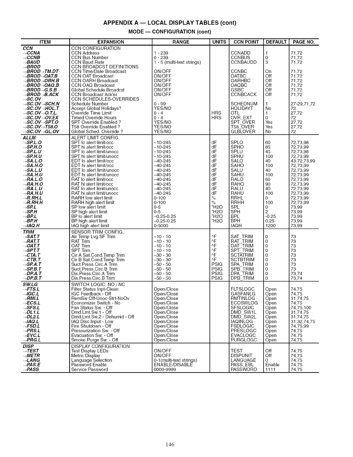
ITEM
CCN
-_CCNA
-_CCNB
-_BAUD
-_BROD
-_BROD-_TM.DT
-_BROD-_OA T.B
-_BROD-_ORH.B
-_BROD-_OAQ.B
-_BROD-_G.S.B
-_BROD-_B.ACK
-_SC.OV
-_SC. OV-_SCH.N
-_SC. OV-_HOL. T
-_SC. OV-_O. T.L.
-_SC. OV-_OVEX
-_SC. OV-_SPT.O
-_SC. OV-_ T58. 0
-_SC. OV-_GL.OV
ALLM
-_SP.L.O
-_SP.H.O
-_SP.L.U
-_SP.H.U
-_SA.L.O
_SA.H.O
_SA.L.U
_SA.H.U
_RA.L.O
_RA.H.O
_RA.L.U
_RA.H.U
_R.RH.L
_R.RH.H
_SP.L
_SP.H
_BP.L
_BP.H
_IAQ.H
TRIM
_SAT. T
_RAT.T
_OA T.T
_SPT. T
_C TA. T
_CTB.T
_SP.A. T
-_SP.B. T
_DP.A. T
_DP.B.T
SW.LG
_FTS.L
_IGC.L
_RMI.L
_ECS.L
_SFS.L
_DL 1.L
_DL2.L
_IAQ.L
_FSD.L
_PRS.L
_EVC.L
_PRG.L
DISP
_TEST
_METR
_LANG
_PAS.E
-_PASS
APPENDIX A -- LOCAL DISPLAY TABLES (cont)
MODE -- CONFIGURATION (cont)
EXPANSION
CCN CONFIGURATION
CCN Address
CCN Bus Number
CCN Baud Rate
CCN BROADCST DEFINITIONS
CCN Time/Date Broadcast
CCN OAT Broadcast
CCN OARH Broadcast
CCN OAQ Broadcast
Global Schedule Broadcst
CCN Broadcast Ack'er
CCN SCHEDULES-OVERRIDES
Schedule Number
Accept Global Holidays?
Override Time Limit
Timed Override Hours
SPT Override Enabled ?
T58 Override Enabled ?
Global Sched. Override ?
ALERT LIMIT CONFIG.
SPT Io alert limit/occ
SPT hi alert limit/occ
SPT Io alert limit/unocc
SPT hi alert limit/unocc
EDT Io alert limit/occ
EDT hi alert limit/occ
EDT Io alert limit/unocc
EDT hi alert limit/unocc
RAT Io alert limit/occ
RAT hi alert limit/occ
RAT Io alert limit/unocc
RAT hi alert limit/unocc
RARH low alert limit
RARH high alert limit
SP low alert limit
SP high alert limit
BP Io alert limit
BP high alert limit
IAQ high alert limit
SENSOR TRIM CONFIG.
Air Temp Lvg SF Trim
RAT Trim
OAT Trim
SPT Trim
Cir A Sat.Cond.Temp Trim
Cir B Sat.Cond.Temp Trim
Suct.Press.Circ.A Trim
Suct.Press.Circ.B Trim
Dis.Press.Circ.A Trim
Dis.Press.Circ.B Trim
SWITCH LOGIC: NO /NC
Filter Status Inpt-Clean
IGC Feedback - Off
RemSw Off-Unoc-Strt-NoOv
Economizer Switch - No
Fan Status Sw. - Off
Dmd.Lmt.Sw.1 - Off
Dmd.Lmt.Sw.2 - Dehumid - Off
IAQ Disc.Input - Low
Fire Shutdown - Off
Pressurization Sw. - Off
Evacuation Sw. - Off
Smoke Purge Sw. - Off
DISPLAY CONFIGURATION
Test Display LEDs
Metric Display
Language Selection
Password Enable
Service Password
RANGE UNITS
1 - 239
0 - 239
1 - 5 (multi-text strings)
ON/OFF
ON/OFF
ON/OFF
ON/OFF
ON/OFF
ON/OFF
0 - 99
YES/NO
0-4
0-4
YES/NO
YES/NO
YES/NO
-10-245
-10-245
-10-245
-10-245
-40-245
-40-245
-40-245
-40-245
-40-245
-40-245
-40-245
-40-245
0-100
0-100
0-5
0-5
-0.25-0.25
-0.25-0.25
0-5000
-10-10
-10-10
-10-10
-10-10
-30-30
-30-30
-50-50
-50-50
-50-50
-50-50
Open/Close
Open/Close
Open/Close
Open/Close
Open/Close
Open/Close
Open/Close
Open/Close
Open/Close
Open/Close
Open/Close
Open/Close
ON/OFF
ON/OFF
0-1 (multi-text strings)
ENABLE/DISABLE
0000-9999
HRS
HRS
dF
dF
dF
dF
dF
dF
dF
dF
dF
dF
dF
dF
%
%
"H20
"H20
"H20
"H20
AF
AF
AF
AF
AF
/"F
PSIG
PSIG
PSIG
PSIG
CCN POINT
CCNADD
CCNBUS
CCNBAUDD
CCNBC
OATBC
OARHBC
OAQBC
GSBC
CCNBCACK
SCHEDNUM
HOLIDAYT
OTL
OVR EXT
SPT-OVER
T58-OVER
GLBLOVER
SPLO
SPHO
SPLU
SPHU
SALO
SAHO
SALU
SAHU
RALO
RAHO
RALU
RAHU
RRHL
RRHH
SPL
SPH
BPL
BPH
IAQH
SAT_TRIM
RAT_TRIM
OAT_TRIM
SPT TRIM
SCTATRIM
SCTBTRIM
SPATRIM
SPB TRIM
DPA TRIM
DPB_TRIM
FLTSLOGC
GASFANLG
RMTINLOG
ECOSWLOG
SFSLOGIC
DMD SWl L
DMD SW2L
IAQINLOG
FSDLOGIC
PRESLOGC
EVACLOGC
PURGLOGC
TEST
DISPUNIT
LANGUAGE
PASS EBL
PASSWORD
DEFAULT
1
o
3
On
Off
Off
Off
Off
Off
1
No
1
0
Yes
Yes
No
6O
85
45
IO0
4O
IO0
4O
IO0
6O
9O
4O
IO0
0
IO0
0
2
-0.25
0.25
1200
0
0
0
0
0
0
0
0
0
0
Open
Open
Open
Open
Open
Open
Open
Open
Open
Open
Open
Open
Off
Off
0
Enable
1111
PAGE NO.
71,72
71,72
71,72
71,72
71,72
71,72
71,72
71,72
71,72
27-29,71,72
72
27,72
72
27,72
27,72
72
72,73,98
72,73,99
72,73,98
72,73,99
43,72,73,99
72,73,99
72,73,99
72,73,99
72,73,99
72,73,99
72,73,99
72,73,99
72,73,99
72,73,99
73,99
73,99
73,99
73,99
73,99
73
73
73
73
73
73
73
73
73,74
73,74
74,75
74,75
31,74,75
74,75
74,75,100
31,74,75
31,74,75
31,32,74,75
74,75,99
74,75
74,75
74,75
74,75
74,75
74,75
74,75
74,75
146
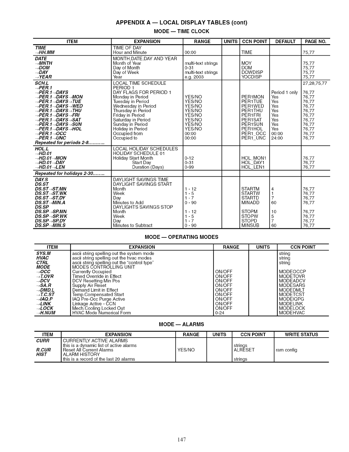
APPENDIX A -- LOCAL DISPLAY TABLES (cont)
MODE -- TIME CLOCK
ITEM
TIME
-_HH. MM
DATE
-_MNTH
-_DOM
-_DAY
-_ YEAR
SCH.L
-_PER. 1
-_PER. I-_DAYS
-_PER. I-_DAYS-_MON
-_PER. I-_DA YS-_ TUE
-_PER. I-_DAYS-_ WED
-_PER. I-_DA YS-_ THU
-_PER. I-_DAYS-_FRI
-_PER. I-_DAYS-_SAT
-_PER. I-_DAYS-_SUN
-_PER. I-_DAYS-_HOL
-_PER. I-_OCC
-_PER. 1-_UNC
Repeated for periods 2-8 ...........
HOL.L
-_HD.01
-_HD.OI-_MON
-_HD.OI-_DAY
-_HD.OI-_LEN
Repeated for holidays 2-30 ........
DAY.S
DS.ST
DS.ST-_ST.MN
DS.ST-_ST. WK
DS.ST-_ST.DY
DS.ST-_MIN.A
DS.SP
DS.SP-_SP.MN
DS.SP-_SP. WK
DS.SP-_SP.DY
D&SP_MIN.S
EXPANSION
TIME OF DAY
Hour and Minute
MONTH,DATE,DAY AND YEAR
Month of Year
Day of Month
Day of Week
Year
LOCAL TIME SCHEDULE
PERIOD 1
DAY FLAGS FOR PERIOD 1
Monday in Period
Tuesday in Period
Wednesday in Period
Thursday in Period
Friday in Period
Saturday in Period
Sunday in Period
Holiday in Period
Occupied from
Occupied to
LOCAL HOLIDAY SCHEDULES
HOLIDAY SCHEDULE 01
Holiday Start Month
Start Day
Duration (Days)
DAYLIGHT SAVINGS TIME
DAYLIGHT SAVINGS START
Month
Week
Day
Minutes to Add
DAYLIGHTS SAVINGS STOP
Month
Week
Day
Minutes to Subtract
RANGE UNITS
00:00
multi-text strings
0-31
multi-text strings
e.g. 2003
YES/NO
YES/NO
YES/NO
YES/NO
YES/NO
YES/NO
YES/NO
YES/NO
00:00
00:00
0-12
0-31
0-99
1-12
1-5
1-7
0-90
1-12
1-5
1-7
0-90
CCN POINT
TIME
MOY
DOM
DOWDISP
YOCDISP
PER1MON
PER1TUE
PER1WED
PER1THU
PER1FRI
PER1SAT
PER1SUN
PER1HOL
PER10CC
PER1 UNC
HOL_MON1
HOL_DAY1
HOL_LEN1
STARTM
STARTW
STARTD
MINADD
STOPM
STOPW
STOPD
MINSUB
DEFAULT
Period 1 only
Yes
Yes
Yes
Yes
Yes
Yes
Yes
Yes
00:00
24:00
4
1
7
6O
lO
5
7
6O
PAGE NO.
75,77
75,77
75,77
75,77
75,77
27,28,75,77
76,77
76,77
76,77
76,77
76,77
76,77
76,77
76,77
76,77
76,77
76,77
76,77
76,77
76,77
76,77
76,77
76,77
76,77
76,77
76,77
76,77
76,77
MODE -- OPERATING MODES
ITEM
SYS.M
HVAC
CTRL
MODE
_OCC
-_ T.OVR
_DCV
_SA.R
_DMD.L
_T.C.ST
_IAQ.P
_LINK
_LOCK
_H.NUM
EXPANSION
ascii string spelling out the system mode
ascii string spelling out the hvac modes
ascii string spelling out the "control type"
MODES CONTROLLING UNIT
Currently Occupied
Timed Override in Effect
DCV Resetting Min Pos
Supply Air Reset
Demand Limit in Effect
Temp.Compensated Start
IAQ Pre-Occ Purge Active
Linkage Active - CCN
Mech.Cooling Locked Out
HVAC Mode Numerical Form
RANGE UNITS
ON/OFF
ON/OFF
ON/OFF
ON/OFF
ON/OFF
ON/OFF
ON/OFF
ON/OFF
ON/OFF
0-24
CCN POINT
string
string
string
MODEOCCP
MODETOVR
MODEADCV
MODESARS
MODEDMLT
MODETCST
MODEIQPG
MODELINK
MODELOCK
MODEHVAC
MODE -- ALARMS
ITEM EXPANSION RANGE UNITS CCN POINT WRITE STATUS
CURR CURRENTLY ACTIVE ALARMS
this is a dynamic list of active alarms strings
R.CUR Reset All Current Alarms YES/NO ALRESET ram config
HIST ALARM HISTORY
this is a record of the last 20 alarms strings
147
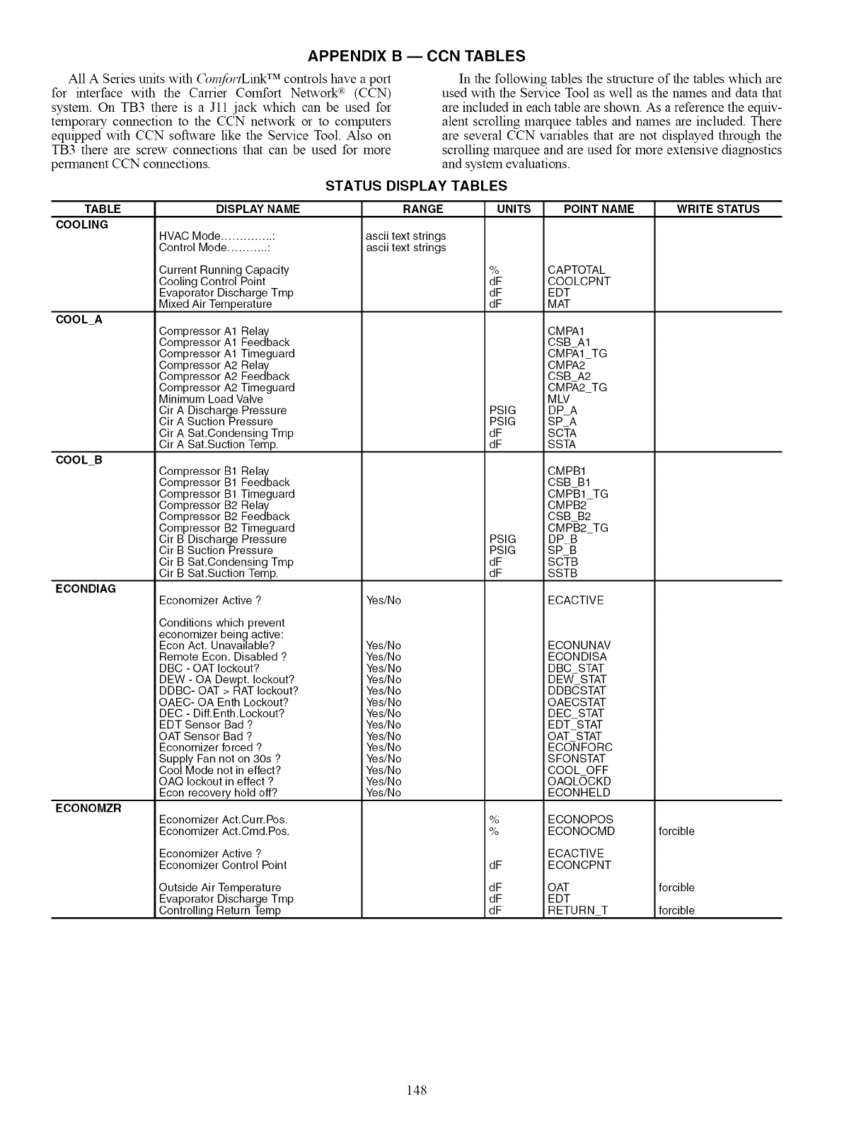
APPENDIX B ECCN TABLES
All A Series units with (_l_?foFtLink TM controls have a port
for interface with the Carrier Comfort Network '_ (CCN)
system. On TB3 there is a Jll jack which can be used for
temporary connection to the CCN network or to computers
equipped with CCN software like the Service Tool. Also on
TB3 there are screw connections that can be used for more
permanent CCN connections.
In the following tables the structure of the tables which are
used with the Service Tool as well as the names and data that
are included in each table are shown. As a reference the equiv-
alent scrolling marquee tables and names are included. There
are several CCN variables that are not displayed through the
scrolling marquee and are used for more extensive diagnostics
and system evaluations.
STATUS DISPLAY TABLES
TABLE
COOLING
COOL_A
COOL_B
ECONDIAG
ECONOMZR
DISPLAY NAME
HVAC Mode .............. :
Control Mode ........... :
Current Running Capacity
Cooling Control Point
Evaporator Discharge Tmp
Mixed Air Temperature
Compressor A1 Relay
Compressor A1 Feedback
Compressor A1 Timeguard
Compressor A2 Relay
Compressor A2 Feedback
Compressor A2 Timeguard
Minimum Load Valve
Cir A Discharge Pressure
Cir A Suction Pressure
Cir A Sat.Condensing Tmp
Cir A Sat.Suction Temp.
Compressor B1 Relay
Compressor B1 Feedback
Compressor B1 Timeguard
Compressor B2 Relay
Compressor B2 Feedback
Compressor B2 Timeguard
Cir B Discharge Pressure
Cir B Suction Pressure
Cir B Sat.Condensing Tmp
Cir B Sat.Suction Temp.
Economizer Active ?
Conditions which prevent
economizer being active:
Econ Act. Unavailable?
Remote Econ. Disabled ?
DBC - OAT lockout?
DEW - OA Dewpt. lockout?
DDBC- OAT > RAT lockout?
OAEC- OA Enth Lockout?
DEC - Diff.Enth.Lockout?
EDT Sensor Bad ?
OAT Sensor Bad ?
Economizer forced ?
Supply Fan not on 30s ?
Cool Mode not in effect?
OAQ lockout in effect ?
Econ recovery hold off?
Economizer Act.Curr.Pos.
Economizer Act.Cmd.Pos.
Economizer Active ?
Economizer Control Point
Outside Air Temperature
Evaporator Discharge Tmp
Controlling Return Temp
RANGE
ascii text strings
ascii text strings
Yes/No
Yes/No
Yes/No
Yes/No
Yes/No
Yes/No
Yes/No
Yes/No
Yes/No
Yes/No
Yes/No
Yes/No
Yes/No
Yes/No
Yes/No
UNITS
%
dF
dF
dF
PSIG
PSIG
dF
dF
PSIG
PSIG
dF
dF
%
%
dF
dF
dF
dF
POINT NAME
CAPTOTAL
COOLCPNT
EDT
MAT
CMPA1
CSB A1
CMPA1 TG
CMPA2
CSB A2
CMPA2_TG
MLV
DPA
SP A
SCTA
SSTA
CMPB1
CSB B1
CMPB1 TG
CMPB2
CSB B2
CMPB2_TG
DPB
SP B
SCaB
SSTB
ECACTIVE
ECONUNAV
ECONDISA
DBC STAT
DEW STAT
DDBCSTAT
OAECSTAT
DEC STAT
EDT STAT
OAT STAT
ECONFORC
SFONSTAT
COOL OFF
OAQLOCKD
ECONHELD
ECONOPOS
ECONOCMD
ECACTIVE
ECONCPNT
OAT
EDT
RETURN_T
WRITE STATUS
forcible
forcible
forcible
148
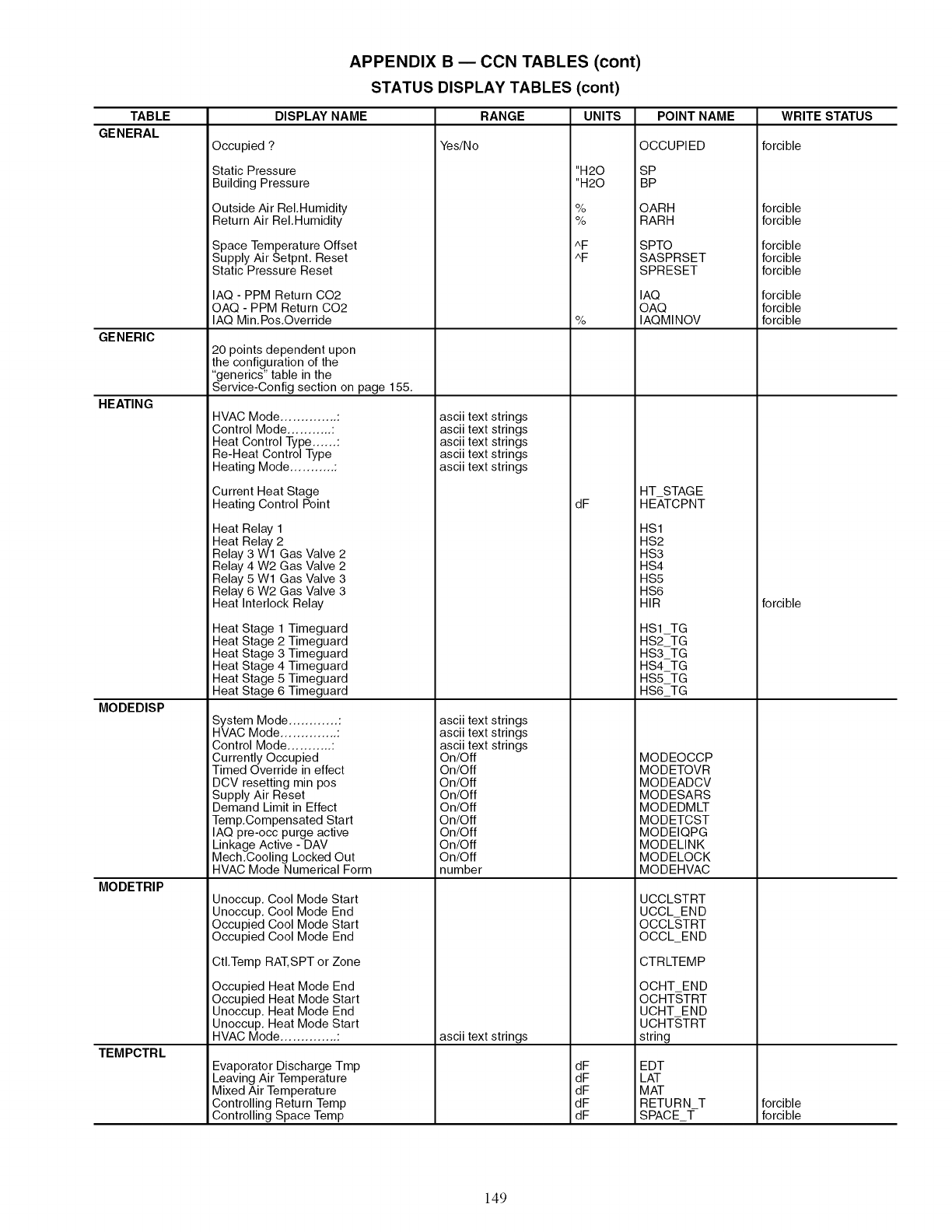
APPENDIX B ECCN TABLES (cont)
STATUS DISPLAY TABLES (cont)
TABLE DISPLAY NAME UNITS POINT NAME
GENERAL
GENERIC
HEATING
MODEDISP
MODETRIP
TEMPCTRL
Occupied ?
Static Pressure
Building Pressure
Outside Air ReI.Humidity
Return Air ReI.Humidity
Space Temperature Offset
Supply Air Setpnt. Reset
Static Pressure Reset
IAQ -PPM Return C02
OAQ - PPM Return C02
IAQ Min.Pos.Override
20 points dependent upon
the configuration of the
"generics" table in the
Service-Config section on page 155.
HVAC Mode .............. :
Control Mode ........... :
Heat Control Type ...... :
Re-Heat Control Type
Heating Mode ........... :
Current Heat Stage
Heating Control Point
Heat Relay 1
Heat Relay 2
Relay 3 Wl Gas Valve 2
Relay 4 W2 Gas Valve 2
Relay 5 Wl Gas Valve 3
Relay 6 W2 Gas Valve 3
Heat Interlock Relay
Heat Stage 1 Timeguard
Heat Stage 2 Timeguard
Heat Stage 3 Timeguard
Heat Stage 4 Timeguard
Heat Stage 5 Timeguard
Heat Stage 6 Timeguard
System Mode ............ :
HVAC Mode .............. :
Control Mode ........... :
Currently Occupied
Timed Override in effect
DCV resetting rain pos
Supply Air Reset
Demand Limit in Effect
Temp.Compensated Start
IAQ pre-occ purge active
Linkage Active - DAV
Mech.Cooling Locked Out
HVAC Mode Numerical Form
Unoccup. Cool Mode Start
Unoccup. Cool Mode End
Occupied Cool Mode Start
Occupied Cool Mode End
CtI.Temp RAT,SPT or Zone
Occupied Heat Mode End
Occupied Heat Mode Start
Unoccup. Heat Mode End
Unoccup. Heat Mode Start
HVAC Mode .............. :
Evaporator Discharge Trap
Leaving Air Temperature
Mixed Air Temperature
Controlling Return Temp
Controlling Space Temp
RANGE
Yes/No
ascii text strings
ascii text strings
ascii text strings
ascii text strings
ascii text strings
ascii text strings
ascii text strings
ascii text strings
On/Off
On/Off
On/Off
On/Off
On/Off
On/Off
On/Off
On/Off
On/Off
number
ascii text strings
"H20
"H20
%
%
AF
AF
%
dF
dF
dF
dF
dF
dF
OCCUPIED
SP
BP
OARH
RARH
SPTO
SASPRSET
SPRESET
IAQ
OAQ
IAQMINOV
HT STAGE
HEATCPNT
HSl
HS2
HS3
HS4
HS5
HS6
HIR
HS1TG
HS2TG
HS3_TG
HS4_TG
HS5TG
HS6_TG
MODEOCCP
MODETOVR
MODEADCV
MODESARS
MODEDMLT
MODETCST
MODEIQPG
MODELINK
MODELOCK
MODEHVAC
UCCLSTRT
UCCL END
OCCLSTRT
OCCL END
CTRWEMP
OCHT END
OCHT,STRT
UCHT END
UCHT,STRT
string
EDT
LAT
MAT
RETURN T
SPACE_T-
WRITE STATUS
forcible
forcible
forcible
forcible
forcible
forcible
forcible
forcible
forcible
forcible
forcible
forcible
149
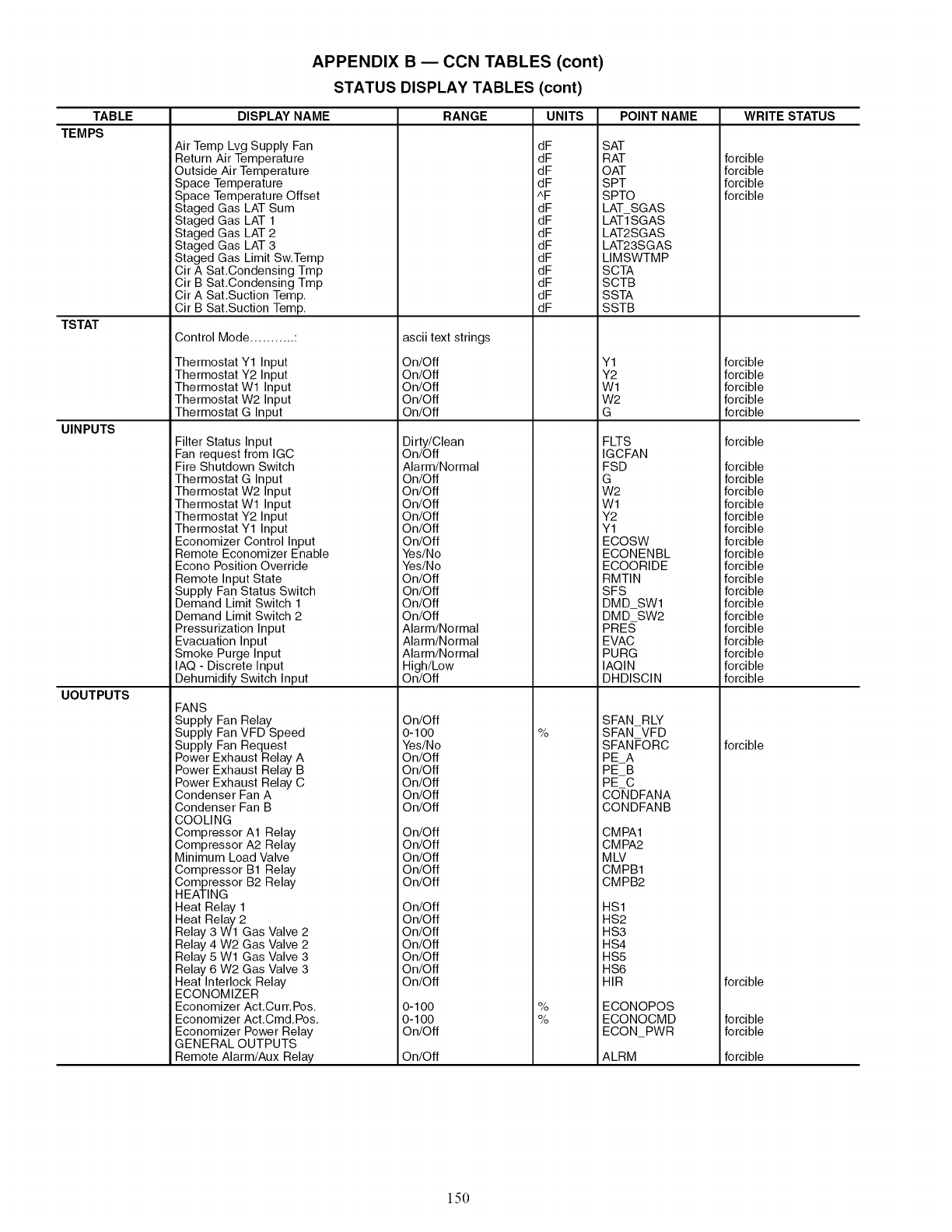
TABLE
TEMPS
TSTAT
UINPUTS
UOUTPUTS
APPENDIX B ECCN TABLES (cont)
STATUS DISPLAY TABLES (cont)
DISPLAY NAME
Air Temp Lvg Supply Fan
Return Air Temperature
Outside Air Temperature
Space Temperature
Space Temperature Offset
Staged Gas LAT Sum
Staged Gas LAT 1
Staged Gas LAT 2
Staged Gas LAT 3
Staged Gas Limit Sw,Temp
Cir A Sat,Condensing Tmp
Cir B Sat,Condensing Tmp
Cir A Sat,Suction Temp,
Cir B Sat,Suction Temp,
Control Mode ........... :
Thermostat Y1 Input
Thermostat Y2 Input
Thermostat Wl Input
Thermostat W2 Input
Thermostat G Input
Filter Status Input
Fan request from IGC
Fire Shutdown Switch
Thermostat G Input
Thermostat W2 Input
Thermostat Wl Input
Thermostat Y2 Input
Thermostat Y1 Input
Economizer Control Input
Remote Economizer Enable
Econo Position Override
Remote Input State
Supply Fan Status Switch
Demand Limit Switch 1
Demand Limit Switch 2
Pressurization Input
Evacuation Input
Smoke Purge Input
IAQ - Discrete Input
Dehumidify Switch Input
FANS
Supply Fan Relay
Supply Fan VFD Speed
Supply Fan Request
Power Exhaust Relay A
Power Exhaust Relay B
Power Exhaust Relay C
Condenser Fan A
Condenser Fan B
COOLING
Compressor A1 Relay
Compressor A2 Relay
Minimum Load Valve
Compressor B1 Relay
Compressor B2 Relay
HEATING
Heat Relay 1
Heat Relay 2
Relay 3 Wl Gas Valve 2
Relay 4 W2 Gas Valve 2
Relay 5 Wl Gas Valve 3
Relay 6 W2 Gas Valve 3
Heat Interlock Relay
ECONOMIZER
Economizer Act,Curr, Pos,
Economizer Act,Cmd,Pos,
Economizer Power Relay
GENERAL OUTPUTS
Remote Alarm/Aux Relay
RANGE UNITS
ascii text strings
On/Off
On/Off
On/Off
On/Off
On/Off
Dirty/Clean
On/Off
Alarm/Normal
On/Off
On/Off
On/Off
On/Off
On/Off
On/Off
Yes/No
Yes/No
On/Off
On/Off
On/Off
On/Off
Alarm/Normal
Alarm/Normal
Alarm/Normal
High/Low
On/Off
On/Off
0-1 O0
Yes/No
On/Off
On/Off
On/Off
On/Off
On/Off
On/Off
On/Off
On/Off
On/Off
On/Off
On/Off
On/Off
On/Off
On/Off
On/Off
On/Off
On/Off
0-1 O0
0-1 O0
On/Off
On/Off
dF
dF
dF
dF
^F
dF
dF
dF
dF
dF
dF
dF
dF
dF
%
%
%
POINT NAME
SAT
RAT
OAT
SPT
SPTO
LAT SGAS
LATI-SGAS
LAT2SGAS
LAT23SGAS
LIMSWTMP
SCTA
SCTB
SSTA
SSTB
Y1
Y2
Wl
W2
G
FLTS
IGCFAN
FSD
G
W2
Wl
Y2
Y1
ECOSW
ECONENBL
ECOORIDE
RMTIN
SFS
DMD SWl
DMD SW2
PRES
EVAC
PURG
IAQIN
DHDISCIN
SFAN RLY
SFAN VFD
SFANFORC
PEA
PEB
PE C
CO-NDFANA
CONDFANB
CMPA1
CMPA2
MLV
CMPB1
CMPB2
HS1
HS2
HS3
HS4
HS5
HS6
HIR
ECONOPOS
ECONOCMD
ECONPWR
ALRM
WRITE STATUS
forcible
forcible
forcible
forcible
forcible
forcible
forcible
forcible
forcible
forcible
forcible
forcible
forcible
forcible
forcible
forcible
forcible
forcible
forcible
forcible
forcible
forcible
forcible
forcible
forcible
forcible
forcible
forcible
forcible
forcible
forcible
forcible
forcible
150
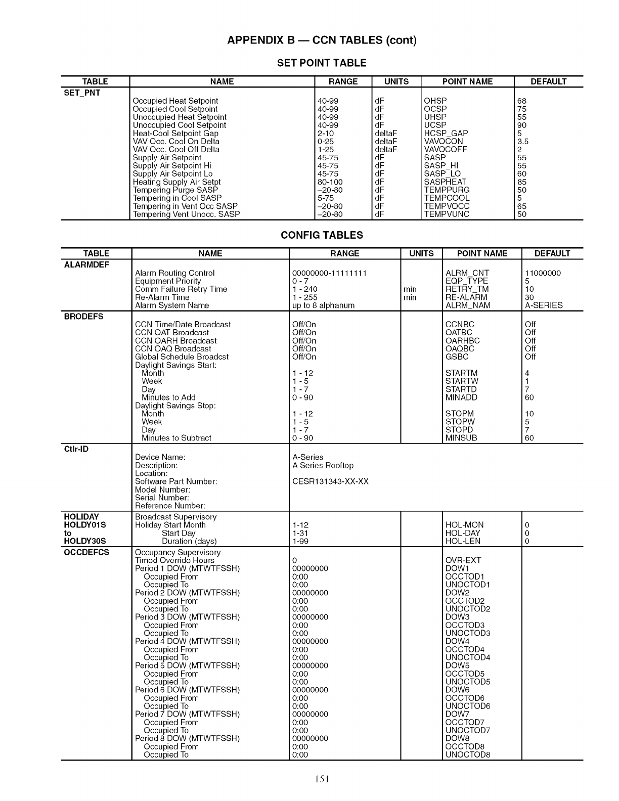
TABLE
SET_PNT
TABLE
ALARMDEF
BRODEFS
Ctlr-ID
HOLIDAY
HOLDY01 S
to
HOLDY30S
OCCDEFCS
APPENDIX B ECCN TABLES (cont)
SET POINT TABLE
NAME RANGE UNITS POINT NAME DEFAULT
Occupied Heat Setpoint
Occupied Cool Setpoint
Unoccupied Heat Setpoint
Unoccupied Cool Setpoint
Heat-Cool Setpoint Gap
VAV Occ. Cool On Delta
VAV Occ. Cool Off Delta
Supply Air Setpoint
Supply Air Setpoint Hi
Supply Air Setpoint Lo
Heating Supply Air Setpt
Tempering Purge SASP
Tempering in Cool SASP
Tempering in Vent Occ SASP
Tempering Vent Unocc. SASP
40-99
40-99
40-99
40-99
2-10
0 -25
1-25
45-75
45-75
45-75
80-1 O0
-20 -80
5 -75
-20-80
-20 -80
dF
dF
dF
dF
deltaF
deltaF
deltaF
dF
dF
dF
dF
dF
dF
dF
dF
OHSP
OCSP
UHSP
UCSP
HCSP GAP
VAVOCON
VAVOCOFF
SASP
SASP HI
SASP LO
SASPHEAT
TEMPPURG
TEMPCOOL
TEMPVOCC
TEMPVUNC
68
75
55
90
5
3.5
2
55
55
60
85
50
5
65
50
CONFIG TABLES
NAME
Alarm Routing Control
Equipment Priority
Comm Failure Retry Time
Re-Alarm Time
Alarm System Name
CCN Time/Date Broadcast
CCN OAT Broadcast
CCN OARH Broadcast
CCN OAQ Broadcast
Global Schedule Broadcst
Daylight Savings Start:
Month
Week
Day
Minutes to Add
Daylight Savings Stop:
Month
Week
Day
Minutes to Subtract
Device Name:
Description:
Location:
Software Part Number:
Model Number:
Serial Number:
Reference Number:
Broadcast Supervisory
Holiday Start Month
Start Day
Duration (days)
Occupancy Supervisory
Timed Override Hours
Period 1 DOW (MTWTFSSH)
Occupied From
Occupied To
Period 2 DOW (MTWTFSSH)
Occupied From
Occupied To
Period 3 DOW (MTWTFSSH)
Occupied From
Occupied To
Period 4 DOW (MTWTFSSH)
Occupied From
Occupied To
Period 5 DOW (MTWTFSSH)
Occupied From
Occupied To
Period 6 DOW (MTWTFSSH)
Occupied From
Occupied To
Period 7 DOW (MTWTFSSH)
Occupied From
Occupied To
Period 8 DOW (MTWTFSSH)
Occupied From
Occupied To
RANGE
00000000-11111111
0-7
1 - 240
1 - 255
up to 8 alphanum
Off/On
Off/On
Off/On
Off/On
Off/On
1 -12
1-5
1-7
0 - 90
1 -12
1-5
1-7
0 - 90
A-Series
A Series Rooftop
CESR131343-XX-XX
1-12
1-31
1-99
o
oooooooo
o:oo
o:oo
oooooooo
o:oo
o:oo
oooooooo
o:oo
o:oo
oooooooo
o:oo
o:oo
oooooooo
o:oo
o:oo
oooooooo
o:oo
o:oo
oooooooo
o:oo
o:oo
oooooooo
o:oo
o:oo
UNITS
rain
rain
POINT NAME
ALRM CNT
EQP TYPE
RETRY TM
RE-ALARM
ALRM_NAM
CCNBC
OATBC
OARHBC
OAQBC
GSBC
STARTM
STARTW
STARTD
MINADD
STOPM
STOPW
STOPD
MINSUB
HOL-MON
HOL-DAY
HOL-LEN
OVR-EXT
DOWl
OCCTOD1
UNOCTOD1
DOW2
OCCTOD2
UNOCTOD2
DOW3
OCCTOD3
UNOCTOD3
DOW4
OCCTOD4
UNOCTOD4
DOW5
OCCTOD5
UNOCTOD5
DOW6
OCCTOD6
UNOCTOD6
DOW7
OCCTOD7
UNOCTOD7
DOW8
OCCTOD8
UNOCTOD8
DEFAULT
11000000
5
10
3O
A-SERIES
Off
Off
Off
Off
Off
4
1
7
60
lO
5
7
60
o
o
o
151
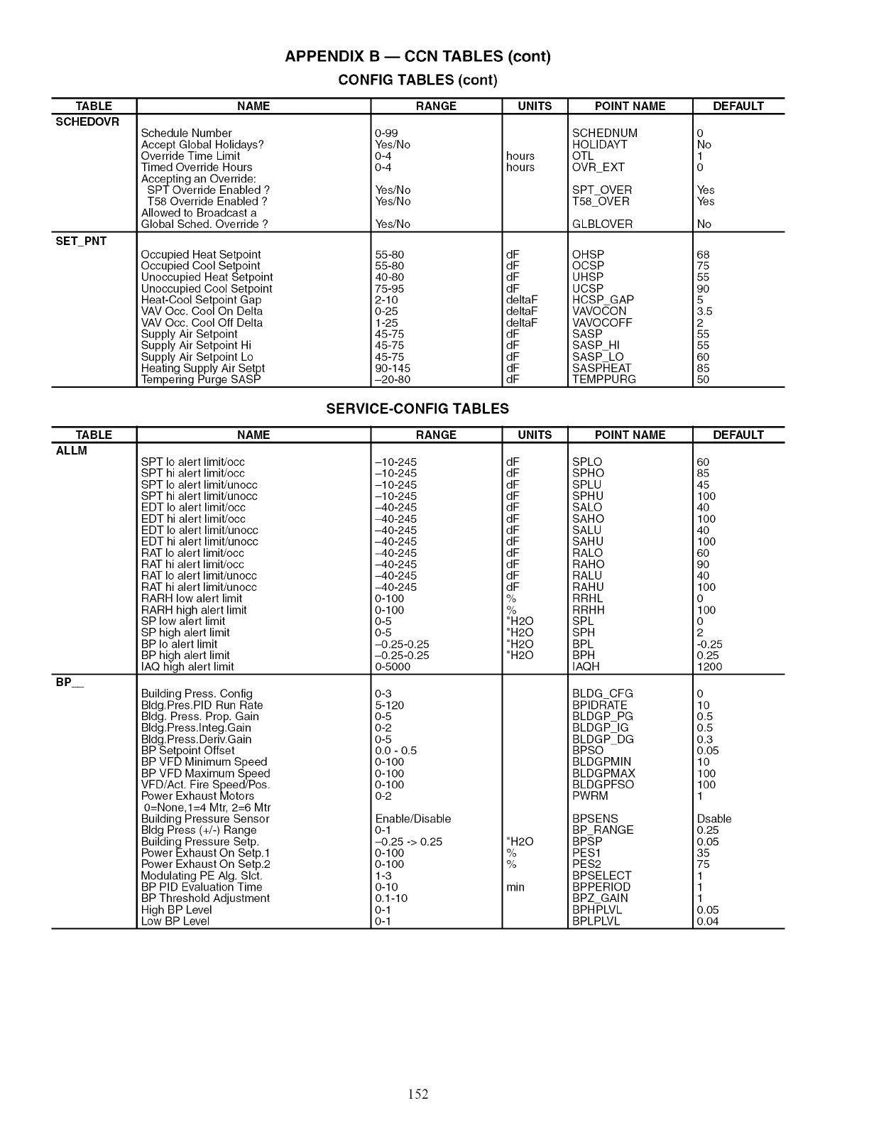
APPENDIX B ECCN TABLES (cont)
CONFIG TABLES (cont)
TABLE NAME RANGE UNITS POINT NAME DEFAULT
SCHEDOVR
SET_PNT
Schedule Number
Accept Global Holidays?
Override Time Limit
Timed Override Hours
Accepting an Override:
SPT Override Enabled ?
T58 Override Enabled ?
Allowed to Broadcast a
Global Sched. Override ?
Occupied Heat Setpoint
Occupied Cool Setpoint
Unoccupied Heat Setpoint
Unoccupied Cool Setpoint
Heat-Cool Setpoint Gap
VAV Occ. Cool On Delta
VAV Occ. Cool Off Delta
Supply Air Setpoint
Supply Air Setpoint Hi
Supply Air Setpoint Lo
Heating Supply Air Setpt
Tempering Purge SASP
0-99
Yes/No
0-4
0-4
Yes/No
Yes/No
Yes/No
55 -80
55-80
40 -80
75-95
2-10
0-25
1-25
45-75
45-75
45-75
90-145
-20-80
hours
hours
dF
dF
dF
dF
deltaF
deltaF
deltaF
dF
dF
dF
dF
dF
SCHEDNUM
HOLIDAYT
OTL
OVR EXT
SPT OVER
T58_OV E R
GLBLOVER
OHSP
OCSP
UHSP
UCSP
HCSP GAP
VAVO CO N
VAVOCOFF
SASP
SASP HI
SASP LO
SASPHEAT
TEMPPURG
0
No
1
0
Yes
Yes
No
68
75
55
90
5
3.5
2
55
55
60
85
50
SERVICE-CONFIG TABLES
TABLE NAME RANGE UNITS POINT NAME DEFAULT
ALLM -10-245
-10-245
-10-245
-10-245
-40-245
-40-245
-40-245
-40-245
-40-245
-40-245
-40-245
-40-245
0-100
0-100
0-5
0-5
-0.25-0.25
-0.25-0.25
0-5000
0-3
5-120
0-5
0-2
0-5
0.0 - 0.5
0-1O0
0-1O0
0-1O0
0-2
dF
dF
dF
dF
dF
dF
dF
dF
dF
dF
dF
dF
%
%
"H20
"H20
"H20
"H20
"H20
%
%
min
SPLO
SPHO
SPLU
SPHU
SALO
SAHO
SALU
SAHU
RALO
RAHO
RALU
RAHU
RRHL
RRHH
SPL
SPH
BPL
BPH
IAQH
BLDG CFG
BPIDR-ATE
BLDGP PG
BLDGP IG
BLDGP DG
BPSO
BLDGPMIN
BLDGPMAX
BLDGPFSO
PWRM
BPSENS
BP RANGE
BPSP
PES1
PES2
BPSELECT
BPPERIOD
BPZ GAIN
BPHPLVL
BPLPLVL
BP
SPT Io alert limit/occ
SPT hi alert limit/occ
SPT Io alert limit/unocc
SPT hi alert limit/unocc
EDT Io alert limit/occ
EDT hi alert limit/occ
EDT Io alert limit/unocc
EDT hi alert limit/unocc
RAT Io alert limit/occ
RAT hi alert limit/occ
RAT Io alert limit/unocc
RAT hi alert limit/unocc
RARH low alert limit
RARH high alert limit
SP low alert limit
SP high alert limit
BP Io alert limit
BP high alert limit
IAQ high alert limit
Building Press. Config
Bldg.Pres.PID Run Rate
Bldg. Press. Prop. Gain
Bldg.Press.lnteg.Gain
Bldg.Press. Deriv.Gain
BP Setpoint Offset
BP VFD Minimum Speed
BP VFD Maximum Speed
VFD/Act. Fire Speed/Pos.
Power Exhaust Motors
O=None,l=4 Mtr, 2=6 Mtr
Building Pressure Sensor
Bldg Press (+/-) Range
Building Pressure Setp.
Power Exhaust On Setp.1
Power Exhaust On Setp.2
Modulating PE AIg. Slct.
BP PID Evaluation Time
BP Threshold Adjustment
High BP Level
Low BP Level
Enable/Disable
0-1
-0.25 -> 0.25
0-1O0
0-1O0
1-3
0-10
0.1-10
0-1
0-1
60
85
45
100
40
100
40
100
60
90
40
100
0
1O0
0
2
-0.25
0.25
1200
o
lO
0.5
0.5
0.3
o.o5
lO
1oo
lOO
1
Dsable
0.25
0.05
35
75
1
1
1
0.05
0.04
152
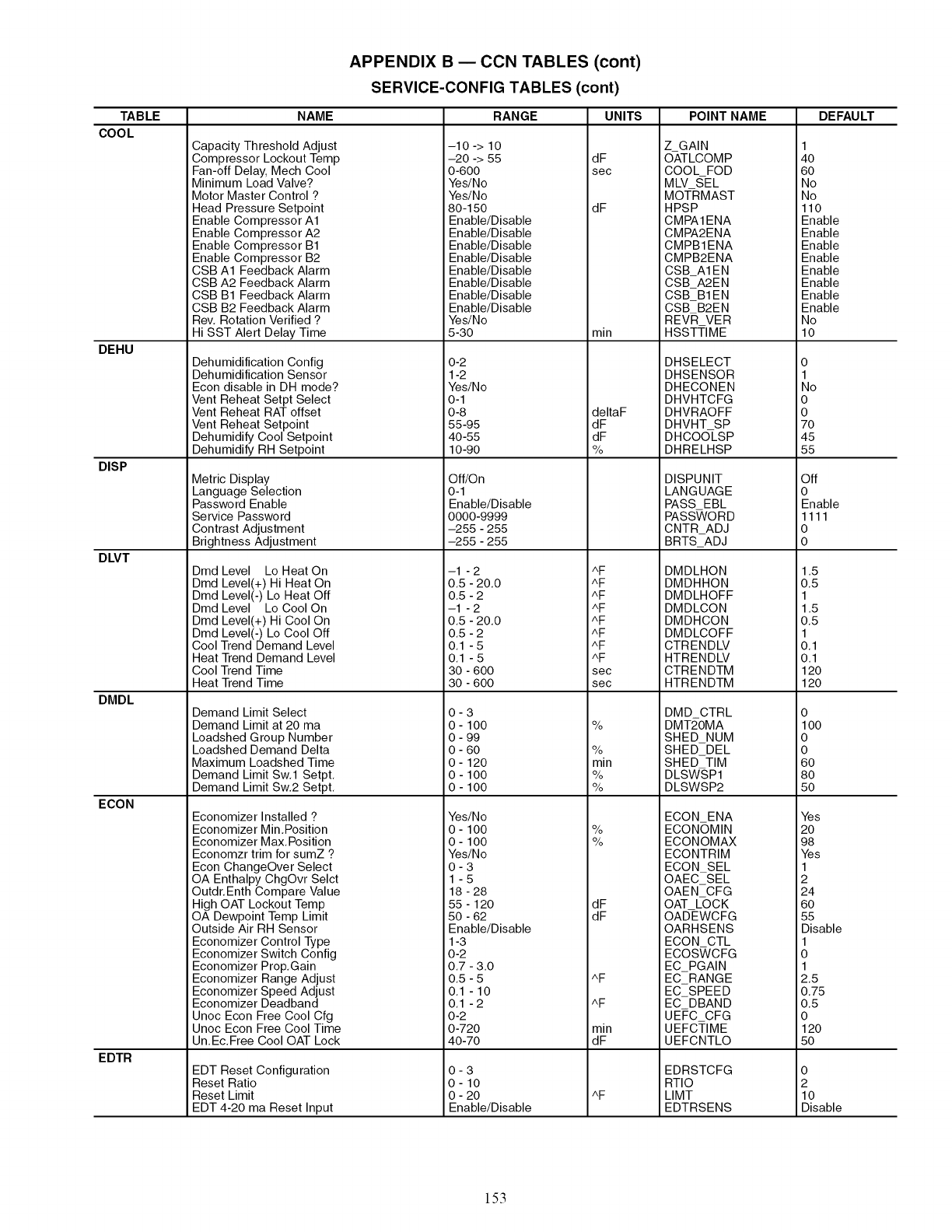
APPENDIX B ECCN TABLES (cont)
SERVICE-CONFIG TABLES (cont)
TABLE NAME RANGE UNITS POINT NAME DEFAULT
COOL
DEHU
DISP
DLVT
DMDL
ECON
EDTR
Capacity Threshold Adjust
Compressor Lockout Temp
Fan-off Delay, Mech Cool
Minimum Load Valve?
Motor Master Control ?
Head Pressure Setpoint
Enable Compressor A1
Enable Compressor A2
Enable Compressor B1
Enable Compressor B2
CSB A1 Feedback Alarm
CSB A2 Feedback Alarm
CSB B1 Feedback Alarm
CSB B2 Feedback Alarm
Rev. Rotation Verified ?
Hi SST Alert Delay Time
Dehumidification Config
Dehumidification Sensor
Econ disable in DH mode?
Vent Reheat Setpt Select
Vent Reheat RAT offset
Vent Reheat Setpoint
Dehumidify Cool Setpoint
Dehumidify RH Setpoint
Metric Display
Language Selection
Password Enable
Service Password
Contrast Adjustment
Brightness Adjustment
Dmd Level Lo Heat On
Dmd Level(+) Hi Heat On
Dmd Level(-) Lo Heat Off
Dmd Level Lo Cool On
Dmd Level(+) Hi Cool On
Dmd Level(-) Lo Cool Off
Cool Trend Demand Level
Heat Trend Demand Level
Cool Trend Time
Heat Trend Time
Demand Limit Select
Demand Limit at 20 ma
Loadshed Group Number
Loadshed Demand Delta
Maximum Loadshed Time
Demand Limit Sw.1 Setpt.
Demand Limit Sw.2 Setpt.
Economizer Installed ?
Economizer Min.Position
Economizer Max. Position
Economzr trim for sumZ ?
Econ ChangeOver Select
OA Enthalpy ChgOvr Selct
Outdr.Enth Compare Value
High OAT Lockout Temp
OA Dewpoint Temp Limit
Outside Air RH Sensor
Economizer Control Type
Economizer Switch Config
Economizer Prop.Gain
Economizer Range Adjust
Economizer Speed Adjust
Economizer Deadband
Unoc Econ Free Cool Cfg
Unoc Econ Free Cool Time
Un.Ec.Free Cool OAT Lock
EDT Reset Configuration
Reset Ratio
Reset Limit
EDT 4-20 ma Reset Input
-10 -> 10
-20 -> 55
0-600
Yes/No
Yes/No
80-150
Enable/Disable
Enable/Disable
Enable/Disable
Enable/Disable
Enable/Disable
Enable/Disable
Enable/Disable
Enable/Disable
Yes/No
5-30
0-2
1-2
Yes/No
0-1
0-8
55-95
40 -55
10-90
Off/On
0-1
Enable/Disable
0000-9999
-255 - 255
-255 - 255
-1 - 2
0.5 - 20.0
0.5 - 2
-1 - 2
0.5 - 20.0
0.5 - 2
0.1 -5
0.1 -5
30 - 600
30 - 600
0-3
O- 100
0 - 99
0 - 60
O- 120
0 - 100
0 - 100
Yes/No
O- 100
O- 100
Yes/No
0-3
1-5
18 - 28
55 - 120
50 - 62
Enable/Disable
1-3
0-2
0.7 - 3.0
0.5 - 5
0.1 - 10
0.1 -2
0-2
0-720
40-70
0-3
0-10
0 - 20
Enable/Disable
dF
sec
dF
min
deltaF
dF
dF
%
AF
AF
AF
AF
AF
AF
AF
AF
sec
sec
%
%
min
%
%
%
%
dF
dF
AF
AF
min
dF
AF
Z GAIN
O-ATLCOMP
COOL FOD
MLV SEL
MOT-RMAST
HPSP
CMPA1ENA
CMPA2ENA
CMPB1ENA
CMPB2ENA
CSBA1EN
CSB A2EN
CSBB1EN
CSB B2EN
REVF{ VER
HSSTTIME
DHSELECT
DHSENSOR
DHECONEN
DHVHTCFG
DHVRAOFF
DHVHT SP
DHCOOLSP
DHRELHSP
DISPUNIT
LANGUAGE
PASS EBL
PASSWORD
CNTR ADJ
BRTS_ADJ
DMDLHON
DMDHHON
DMDLHOFF
DMDLCON
DMDHCON
DMDLCOFF
CTRENDW
HTRENDW
CTRENDTM
HTRENDTM
DMD CTRL
DMT2OMA
SHED NUM
SHED DEL
SHED TIM
DLSWSP1
DLSWSP2
ECON ENA
ECONOMIN
ECONOMAX
ECONTRIM
ECONSEL
OAECSEL
OAENCFG
OAT LOCK
OADEWCFG
OARHSENS
ECON CTL
ECOSWCFG
EC PGAIN
ECRANGE
ECSPEED
EC DBAND
UEFC CFG
UEFCTIME
UEFCNTLO
EDRSTCFG
RTIO
LIMT
EDTRSENS
1
40
60
No
No
110
Enable
Enable
Enable
Enable
Enable
Enable
Enable
Enable
No
10
0
1
No
0
0
7O
45
55
Off
0
Enable
1111
0
0
1.5
0.5
1
1.5
0.5
1
0.1
0.1
120
120
o
1oo
o
o
6o
8o
5o
Yes
20
98
Yes
1
2
24
60
55
Disable
1
0
1
2.5
0.75
0.5
0
120
50
o
2
lO
Disable
153
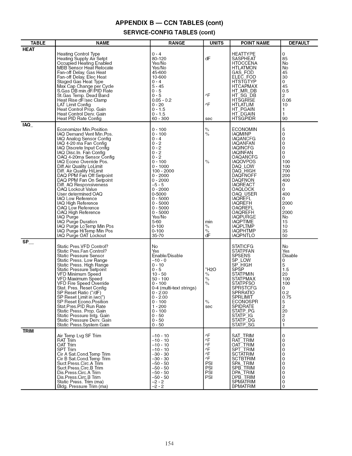
TABLE
HEAT
IAQ_
SP
TRIM
APPENDIX B ECCN TABLES (cont)
SERVICE-CONFIG TABLES (cont)
NAME
Heating Control Type
Heating Supply Air Setpt
Occupied Heating Enabled
MBB Sensor Heat Relocate
Fan-off Delay, Gas Heat
Fan-off Delay, Elec Heat
Staged Gas Heat Type
Max Cap Change per Cycle
S.Gas DB min.dF/PID Rate
St.Gas Temp. Dead Band
Heat Rise dF/sec Clamp
LAT Limit Config
Heat Control Prop. Gain
Heat Control Derv. Gain
Heat PID Rate Config
Economizer Min.Position
IAQ Demand Vent Min.Pos.
IAQ Analog Sensor Config
IAQ 4-20 ma Fan Config
IAQ Discrete Input Config
IAQ Disc.In. Fan Config
OAQ 4-20ma Sensor Config
IAQ Econo Override Pos.
Diff.Air Quality LoLimit
Diff. Air Quality HiLimit
DAQ PPM Fan Off Setpoint
DAQ PPM Fan On Setpoint
Diff. AQ Responsiveness
OAQ Lockout Value
User determined OAQ
IAQ Low Reference
IAQ High Reference
OAQ Low Reference
OAQ High Reference
IAQ Purge
IAQ Purge Duration
IAQ Purge LoTemp Min Pos
IAQ Purge HiTemp Min Pos
IAQ Purge OAT Lockout
Static Pres.VFD Control?
Static Pres.Fan Control?
Static Pressure Sensor
Static Press. Low Range
Static Press. High Range
Static Pressure Setpoint
VFD Minimum Speed
VFD Maximum Speed
VFD Fire Speed Override
Stat. Pres. Reset Config
SP Reset Ratio ("/dF)
SP Reset Limit in iwc(")
SP Reset Econo.Position
Stat.Pres.PID Run Rate
Static Press. Prop. Gain
Static Pressure Intg. Gain
Static Pressure Derv. Gain
Static Press.System Gain
Air Temp Lvg SF Trim
RAT Trim
OAT Trim
SPT Trim
Cir A Sat.Cond.Temp Trim
Cir B Sat.Cond.Temp Trim
Suct.Press.Circ.A Trim
Suct.Press.Circ.B Trim
Dis.Press.Circ.A Trim
Dis.Press.Circ.B Trim
Static Press. Trim (ma)
Bldg. Pressure Trim (ma)
RANGE
0-4
80-120
Yes/No
Yes/No
45-600
10-600
0-4
5 - 45
0-5
0-5
0.05 - 0.2
0 - 20
0 - 1.5
0 - 1.5
60 - 300
0- 100
0- 100
0-4
0-2
0-2
0-2
0-2
0 - 100
0 - 1000
100 - 2000
0 - 2000
0 - 2000
-5 - 5
0 - 2000
0-5000
0 - 5000
0 - 5000
0 - 5000
0 - 5000
Yes/No
5-60
0-100
0-100
35 -70
No
Yes
Enable/Disable
-10 - 0
0-10
0-5
10 - 50
50 - 100
0- 100
0-4 (multi-text strings)
0 - 2.00
0 - 2.00
0- 100
1 - 200
0- 100
0 - 50
0 - 50
0 - 50
-10 - 10
-10 - 10
-10 - 10
-10 - 10
-30 - 30
-30 - 30
-50 - 50
-50 - 50
-50 - 50
-50 - 50
-2 - 2
-2 - 2
UNITS
dF
AF
AF
sec
%
%
%
min
%
%
dF
"H20
%
%
%
%
sec
AF
AF
AF
AF
AF
AF
PSl
PSl
PSl
PSl
POINT NAME
HEATTYPE
SASPHEAT
HTOCCENA
HTLATMON
GAS FOD
ELE(7, FOD
HTSTGTYP
HTCAPMAX
HT MR DB
HT SG DB
HTSGRISE
HTLATLIM
HT_PGAIN
HT DGAIN
HT,SGPIDR
ECONOMIN
IAQMINP
IAQANCFG
IAQANFAN
IAQINCFG
IAQINFAN
OAQANCFG
IAQOVPOS
DAQ_LOW
DAQ HIGH
DAQFNOFF
DAQFNON
IAQREACT
OAQLOCK
OAQ USER
IAQREFL
IAQREFH
OAQREFL
OAQREFH
IAQPURGE
IAQPTIME
IAQP_MP
IAQPHTMP
IAQPNTLO
STATICFG
STATPFAN
SPSENS
SPLOW
SP HIGH
SP,SP
STATPMIN
STATPMAX
STATPFSO
SPRSTCFG
SPRRATIO
SPRLIMIT
ECONOSPR
SPIDRATE
STATP PG
STATP IG
STATP DG
STATP_SG
SAT_TRIM
RAT_TRIM
OAT_TRIM
SPT TRIM
SCT_,TRIM
SCTBTRIM
SPATRIM
SPB TRIM
DPA TRIM
DPB TRIM
SPMATRIM
BPMATRIM
DEFAULT
o
85
No
No
45
30
0
45
0.5
2
0.06
10
1
1
90
5
0
0
0
0
0
0
100
100
700
200
400
0
0
400
0
2000
0
2000
No
15
10
35
50
No
Yes
Disable
0
5
1.5
20
100
100
0
0.2
0.75
5
2
20
2
0
1
0
0
0
0
0
0
0
0
0
0
0
0
154
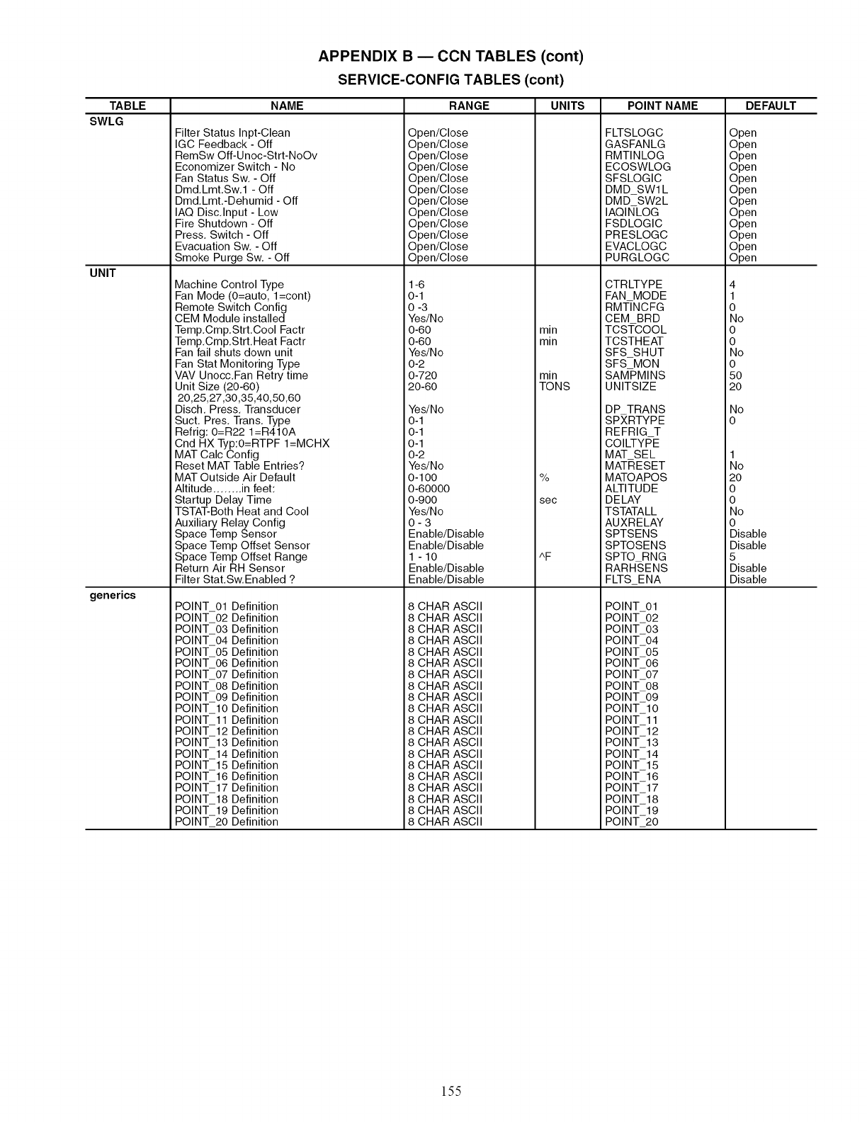
APPENDIX B ECCN TABLES (cont)
SERVICE-CONFIG TABLES (cont)
TABLE NAME RANGE UNITS POINT NAME DEFAULT
SWLG
UNIT
generics
Filter Status Inpt-Clean
IGC Feedback - Off
RemSw Off-Unoc-Strt-NoOv
Economizer Switch - No
Fan Status Sw. - Off
Dmd.Lmt.Sw.1 - Off
Dmd.Lmt.-Dehumid - Off
IAQ Disc.Input - Low
Fire Shutdown - Off
Press. Switch - Off
Evacuation Sw. - Off
Smoke Purge Sw. - Off
Open/Close
Open/Close
Open/Close
Open/Close
Open/Close
Open/Close
Open/Close
Open/Close
Open/Close
Open/Close
Open/Close
Open/Close
FLTSLOGC
GASFANLG
RMTINLOG
ECOSWLOG
SFSLOGIC
DMD SWl L
DMD SW2L
IAQINLOG
FSDLOGIC
PRESLOGC
EVACLOGC
PURGLOGC
Machine Control Type
Fan Mode (O=auto, l=cont)
Remote Switch Config
CEM Module installed
Temp.Cmp.Strt.Cool Factr
Temp.Cmp.Strt.Heat Factr
Fan fail shuts down unit
Fan Stat Monitoring Type
VAV Unocc.Fan Retry time
Unit Size (20-60)
20,25,27,30,35,40,50,60
Disch. Press. Transducer
Suct. Pres. Trans. Type
Refrig: 0=R22 1=R410A
Cnd HX Typ:O=RTPF I=MCHX
MAT Calc Config
Reset MAT Table Entries?
MAT Outside Air Default
Altitude ........ in feet:
Startup Delay Time
TSTAT-Both Heat and Cool
Auxiliary Relay Config
1-6
0-1
0-3
Yes/No
0-60
0-60
Yes/No
0-2
0-720
20-60
Yes/No
0-1
0-1
0-1
0-2
Yes/No
0-1O0
0-60000
0-900
Yes/No
0-3
CTRLTYPE
FAN MODE
RMT/NCFG
CEM BRD
min TCSTCOOL
min TCSTHEAT
SFS SHUT
SFS MON
min SAMPMINS
TONS UNITSIZE
DP TRANS
SPXRTYPE
REFRIG T
COILTYPE
MAT SEL
MATRESET
% MATOAPOS
ALTITUDE
sec DE LAY
TSTATALL
AUXRELAY
Space Temp Sensor
Space Temp Offset Sensor
Space Temp Offset Range
Return Air RH Sensor
Filter Stat.Sw.Enabled ?
POINT 01 Definition
POINT 02 Definition
POINT 03 Definition
POINT 04 Definition
POINT 05 Definition
POINT 06 Definition
POINT 07 Definition
POINT 08 Definition
POINT 09 Definition
POINT 10 Definition
POINT 11 Definition
POINT 12 Definition
POINT 13 Definition
POINT 14 Definition
POINT 15 Definition
POINT 16 Definition
POINT 17 Definition
POINT 18 Definition
POINT 19 Definition
POINT 20 Definition
Enable/Disable
Enable/Disable
1 -10
Enable/Disable
Enable/Disable
8 CHAR ASCII
8 CHAR ASCII
8 CHAR ASCII
8 CHAR ASCII
8 CHAR ASCII
8 CHAR ASCII
8 CHAR ASCII
8 CHAR ASCII
8 CHAR ASCII
8 CHAR ASCII
8 CHAR ASCII
8 CHAR ASCII
8 CHAR ASCII
8 CHAR ASCII
8 CHAR ASCII
8 CHAR ASCII
8 CHAR ASCII
8 CHAR ASCII
8 CHAR ASCII
8 CHAR ASCII
^F
SPTSENS
SPTOSENS
SPTO RNG
RARH-SENS
FLTS ENA
POINT 01
POINT 02
POINT 03
POINT 04
POINT 05
POINT 06
POINT 07
POINT 08
POINT 09
POINT 10
POINT 11
POINT 12
POINT 13
POINT 14
POINT 15
POINT 16
POINT 17
POINT 18
POINT 19
POINT 20
Open
Open
Open
Open
Open
Open
Open
Open
Open
Open
Open
Open
4
1
0
No
0
0
No
0
5O
2O
No
o
1
No
2O
0
0
No
0
Disable
Disable
5
Disable
Disable
155
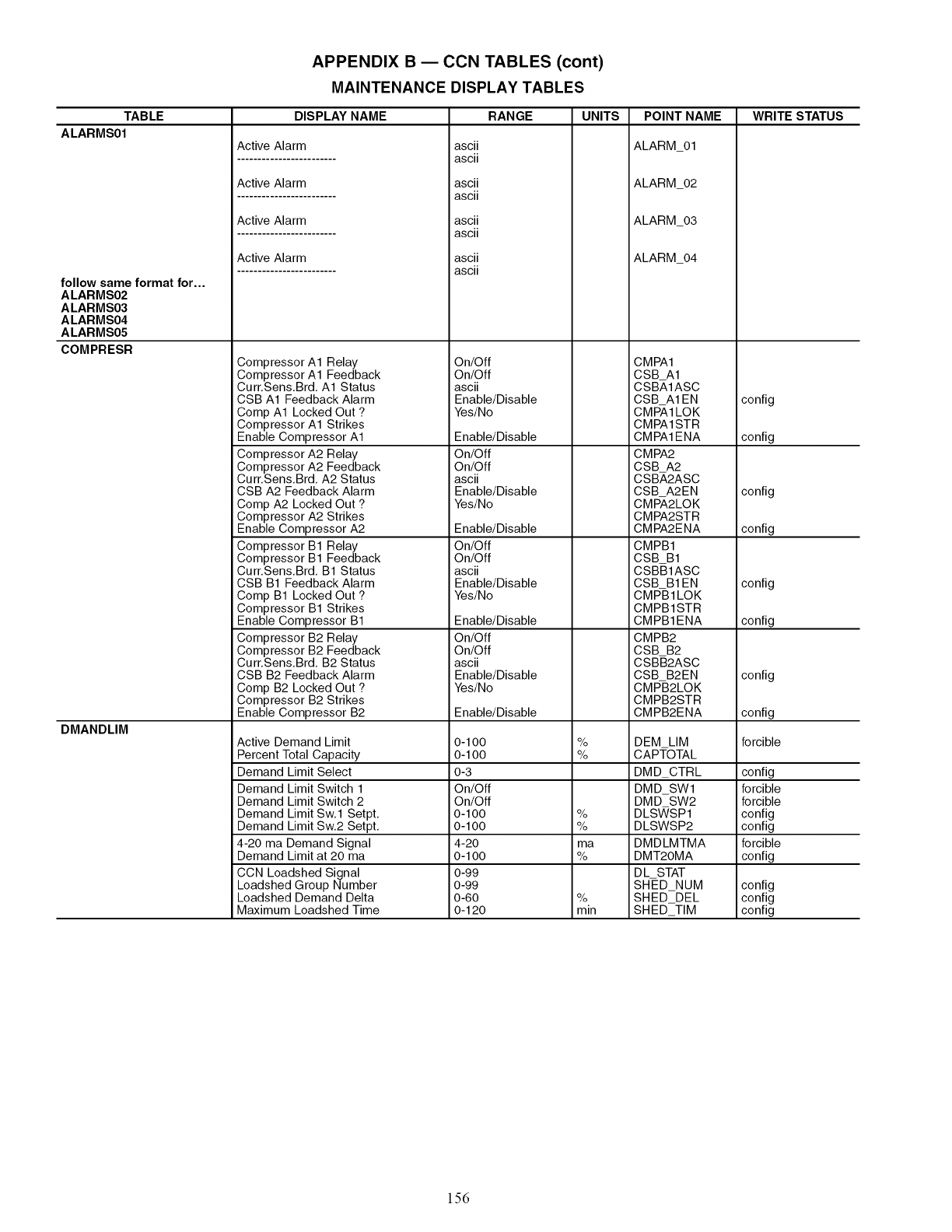
TABLE
ALARMS01
follow same format for...
ALARMS02
ALARMS03
ALARMS04
ALARMS05
COMPRESR
DMANDLIM
APPENDIX B ECCN TABLES (cont)
MAINTENANCE DISPLAY TABLES
DISPLAY NAME
Active Alarm
Active Alarm
Active Alarm
Active Alarm
Compressor A1 Relay
Compressor A1 Feedback
Curr.Sens.Brd. A1 Status
CSB A1 Feedback Alarm
Comp A1 Locked Out ?
Compressor A1 Strikes
Enable Compressor A1
Compressor A2 Relay
Compressor A2 Feedback
Curr.Sens.Brd. A2 Status
CSB A2 Feedback Alarm
Comp A2 Locked Out ?
Compressor A2 Strikes
Enable Compressor A2
Compressor B1 Relay
Compressor B1 Feedback
Curr.Sens.Brd. B1 Status
CSB B1 Feedback Alarm
Comp B1 Locked Out ?
Compressor B1 Strikes
Enable Compressor B1
Compressor B2 Relay
Compressor B2 Feedback
Curr.Sens.Brd. B2 Status
CSB B2 Feedback Alarm
Comp B2 Locked Out ?
Compressor B2 Strikes
Enable Compressor B2
Active Demand Limit
Percent Total Capacity
Demand Limit Select
Demand Limit Switch 1
Demand Limit Switch 2
Demand Limit Sw.1 Setpt.
Demand Limit Sw.2 Setpt.
4-20 ma Demand Signal
Demand Limit at 20 ma
CCN Loadshed Signal
Loadshed Group Number
Loadshed Demand Delta
Maximum Loadshed Time
RANGE UNITS
ascii
ascii
ascii
ascii
ascii
ascii
ascii
ascii
On/Off
On/Off
ascii
Enable/Disable
Yes/No
Enable/Disable
On/Off
On/Off
ascii
Enable/Disable
Yes/No
Enable/Disable
On/Off
On/Off
ascii
Enable/Disable
Yes/No
Enable/Disable
On/Off
On/Off
ascii
Enable/Disable
Yes/No
Enable/Disable
0-100
0-100
0-3
On/Off
On/Off
0-100
0-100
4-20
0-100
0-99
0 -99
0-60
0-120
%
%
%
%
ma
%
%
min
POINT NAME
ALARM_01
ALARM_02
ALARM_03
ALARM_04
CMPA1
CSB A1
CSB_,IASC
CSB A1EN
CMPA1LOK
CMPA1STR
CMPA1ENA
CMPA2
CSB A2
CSB_,2ASC
CSB A2EN
CMPA2LOK
CMPA2STR
CMPA2ENA
CMPB1
CSB B1
CSBB1ASC
CSB B1EN
CMPB1LOK
CMPB1STR
CMPB1ENA
CMPB2
CSB B2
CSBB2ASC
CSB B2EN
CMPB2LOK
CMPB2STR
CMPB2ENA
DEM LIM
CAPTOTAL
DMD_CTRL
DMD SW1
DMD SW2
DLS'_SP1
DLSWSP2
DMDLMTMA
DMT20MA
DL STAT
SHED NUM
SHED DEL
SHEDTIM
WRITE STATUS
config
config
config
config
config
config
config
config
forcible
config
forcible
forcible
config
config
forcible
config
config
config
config
156
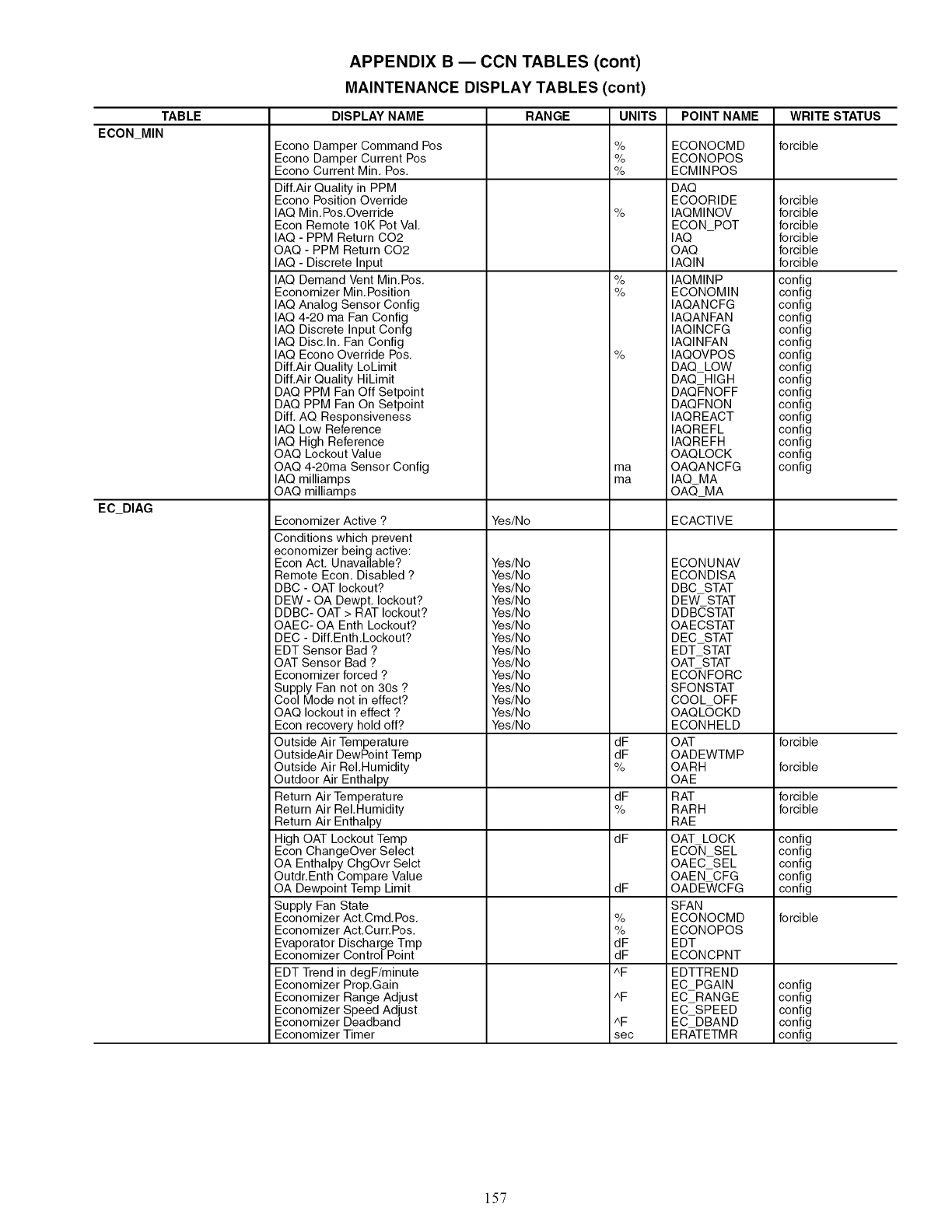
TABLE
ECON MIN
EC_DIAG
APPENDIX B ECCN TABLES (cont)
MAINTENANCE DISPLAY TABLES (cont)
DISPLAY NAME
Econo Damper Command Pos
Econo Damper Current Pos
Econo Current Min. Pos.
Dill.Air Quality in PPM
Econo Position Override
IAQ Min.Pos.Override
Econ Remote 10K Pot Val.
IAQ - PPM Return C02
OAQ - PPM Return C02
IAQ - Discrete Input
IAQ Demand Vent Min.Pos.
Economizer Min.Position
IAQ Analog Sensor Config
IAQ 4-20 ma Fan Config
IAQ Discrete Input Confg
IAQ Disc.In. Fan Config
IAQ Econo Override Pos.
Dill.Air Quality LoLimit
Dill.Air Quality HiLimit
DAQ PPM Fan Off Setpoint
DAQ PPM Fan On Setpoint
Diff. AQ Responsiveness
IAQ Low Reference
IAQ High Reference
OAQ Lockout Value
OAQ 4-20ma Sensor Config
IAQ milliamps
OAQ milliamps
Economizer Active ?
Conditions which prevent
economizer being active:
Econ Act. Unavailable?
Remote Econ. Disabled ?
DBC - OAT lockout?
DEW - OA Dewpt. lockout?
DDBC- OAT > RAT lockout?
OAEC- OA Enth Lockout?
DEC - Diff.Enth.Lockout?
EDT Sensor Bad ?
OAT Sensor Bad ?
Economizer forced ?
Supply Fan not on 30s ?
Cool Mode not in effect?
OAQ lockout in effect ?
Econ recovery hold off?
Outside Air Temperature
OutsideAir DewPoint Temp
Outside Air ReI.Humidity
Outdoor Air Enthalpy
Return Air Temperature
Return Air ReI.Humidity
Return Air Enthalpy
High OAT Lockout Temp
Econ ChangeOver Select
OA Enthalpy ChgOvr Selct
Outdr.Enth Compare Value
OA Dewpoint Temp Limit
Supply Fan State
Economizer Act.Cmd.Pos.
Economizer Act.Curr.Pos.
Evaporator Discharge Tmp
Economizer Control Point
EDT Trend in degF/minute
Economizer Prop.Gain
Economizer Range Adjust
Economizer Speed Adjust
Economizer Deadband
Economizer Timer
RANGE UNITS
Yes/No
Yes/No
Yes/No
Yes/No
Yes/No
Yes/No
Yes/No
Yes/No
Yes/No
Yes/No
Yes/No
Yes/No
Yes/No
Yes/No
Yes/No
%
%
%
%
%
%
%
ma
ma
dF
dF
%
dF
%
dF
dF
%
%
dF
dF
^F
^F
^F
sec
POINT NAME
ECONOCMD
ECONOPOS
ECMINPOS
DAQ
ECOORIDE
IAQMINOV
ECON POT
IAQ
OAQ
IAQIN
IAQMINP
ECONOMIN
IAQANCFG
IAQANFAN
IAQINCFG
IAQINFAN
IAQOVPOS
DAQ LOW
DAQ HIGH
DAQFNOFF
DAQFNON
IAQREACT
IAQREFL
IAQREFH
OAQLOCK
OAQANCFG
IAQ MA
OAQMA
ECACTIVE
ECONUNAV
ECONDISA
DBC STAT
DEW- STAT
DDBCSTAT
OAECSTAT
DEC STAT
EDT STAT
OAT STAT
ECONFORC
SFONSTAT
COOL OFF
OAQLOCKD
ECONHELD
OAT
OADEWTMP
OARH
OAE
RAT
RARH
RAE
OAT LOCK
ECON SEL
OAEC SEL
OAEN CFG
OADE_/CFG
SFAN
ECONOCMD
ECONOPOS
EDT
ECONCPNT
EDTTREND
EC PGAIN
EC RANGE
EC SPEED
EC DBAND
ERATETMR
WRITE STATUS
forcible
forcible
forcible
forcible
forcible
forcible
forcible
config
config
config
config
config
config
config
config
config
config
config
config
config
config
config
config
forcible
forcible
forcible
forcible
config
config
config
config
config
forcible
config
config
config
config
config
157
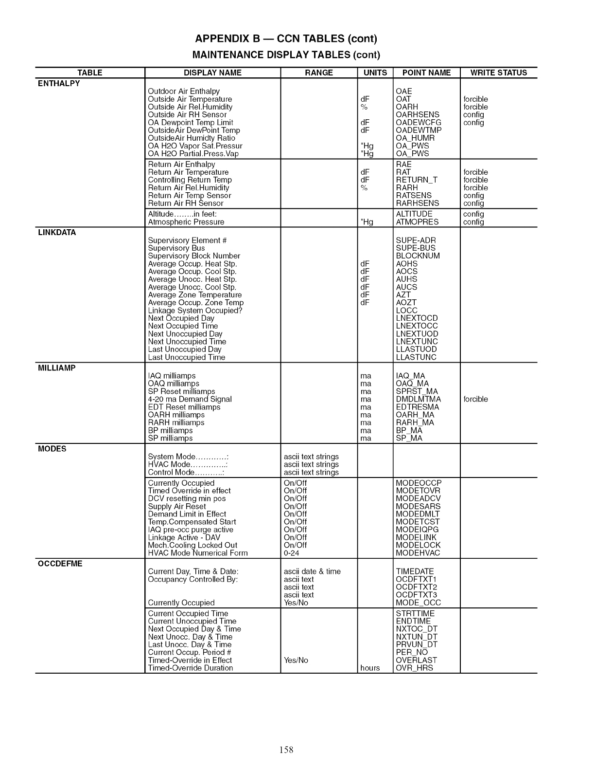
TABLE
ENTHALPY
LINKDATA
MILLIAMP
MODES
OCCDEFME
APPENDIX B ECCN TABLES (cont)
MAINTENANCE DISPLAY TABLES (cont)
DISPLAY NAME
Outdoor Air Enthalpy
Outside Air Temperature
Outside Air ReI.Humidity
Outside Air RH Sensor
OA Dewpoint Temp Limit
OutsideAir DewPoint Temp
OutsideAir Humidty Ratio
OA H20 Vapor Sat.Pressur
OA H20 PartiaI.Press.Vap
Return Air Enthalpy
Return Air Temperature
Controlling Return Temp
Return Air ReI.Humidity
Return Air Temp Sensor
Return Air RH Sensor
Altitude ........ in feet:
Atmospheric Pressure
Supervisory Element #
Supervisory Bus
Supervisory Block Number
Average Occup. Heat Stp.
Average Occup. Cool Stp.
Average Unocc. Heat Stp.
Average Unocc. Cool Stp.
Average Zone Temperature
Average Occup. Zone Temp
Linkage System Occupied?
Next Occupied Day
Next Occupied Time
Next Unoccupied Day
Next Unoccupied Time
Last Unoccupied Day
Last Unoccupied Time
IAQ milliamps
OAQ milliamps
SP Reset milliamps
4-20 ma Demand Signal
EDT Reset milliamps
OARH milliamps
RARH milliamps
BP milliamps
SP milliamps
System Mode ............ :
HVAC Mode .............. :
Control Mode ........... :
Currently Occupied
Timed Override in effect
DCV resetting min pos
Supply Air Reset
Demand Limit in Effect
Temp.Compensated Start
IAQ pre-occ purge active
Linkage Active - DAV
Mech.Cooling Locked Out
HVAC Mode Numerical Form
Current Day, Time & Date:
Occupancy Controlled By:
Currently Occupied
Current Occupied Time
Current Unoccupied Time
Next Occupied Day & Time
Next Unocc. Day & Time
Last Unocc. Day & Time
Current Occup. Period #
Timed-Override in Effect
Timed-Override Duration
RANGE UNITS
ascii text strings
ascii text strings
ascii text strings
On/Off
On/Off
On/Off
On/Off
On/Off
On/Off
On/Off
On/Off
On/Off
0-24
ascii date & time
ascii text
ascii text
ascii text
Yes/No
Yes/No
dF
%
dF
dF
"Hg
"Hg
dF
dF
%
"Hg
dF
dF
dF
dF
dF
dF
ma
ma
ma
ma
ma
ma
ma
ma
ma
hours
POINT NAME
OAE
OAT
OARH
OARHSENS
OADEWCFG
OADEWTMP
OA HUMR
OAPWS
OA_PWS
RAE
RAT
RETURN_T
RARH
RATSENS
RARHSENS
ALTITUDE
ATMOPRES
SUPE-ADR
SUPE-BUS
BLOCKNUM
AOHS
AOCS
AUHS
AUCS
AZT
AOZT
LOCC
LNEXTOCD
LNEXTOCC
LNEXTUOD
LNEXTUNC
LLASTUOD
LLASTUNC
IAQ MA
OAC_ MA
SPRST MA
DMDLMTMA
EDTRESMA
OARH MA
RARH MA
BPM, _,
SPMA
MODEOCCP
MODETOVR
MODEADCV
MODESARS
MODEDMLT
MODETCST
MODEIQPG
MODELINK
MODELOCK
MODEHVAC
TIMEDATE
OCDFTXT1
OCDFTXT2
OCDFTXT3
MODE OCC
STRTTIME
ENDTIME
NXTOC DT
NXTUN DT
PRVUN DT
PER N(D
OVEF{LAST
OVR HRS
WRITE STATUS
forcible
forcible
config
config
forcible
forcible
forcible
config
config
config
config
forcible
158
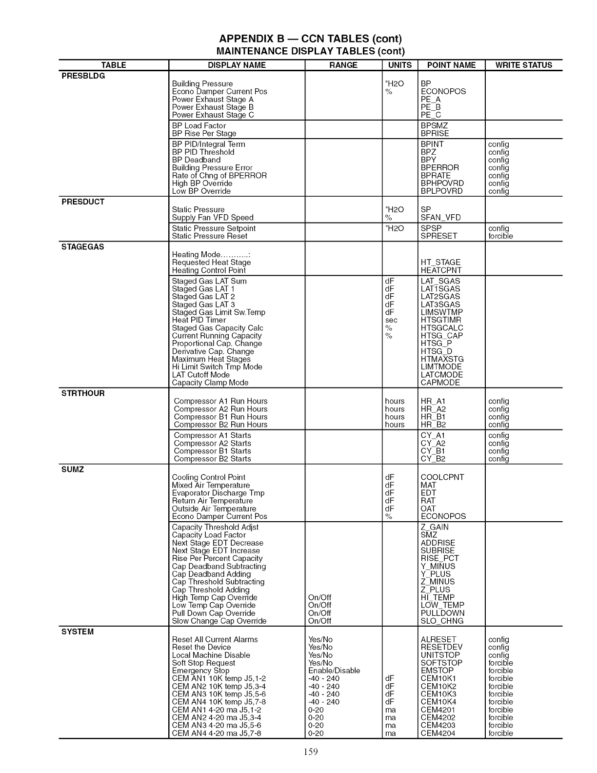
TABLE
PRESBLDG
PRESDUCT
STAGEGAS
STRTHOUR
SUMZ
SYSTEM
APPENDIX B ECCN TABLES (cont)
MAINTENANCE DISPLAY TABLES (cont)
DISPLAY NAME RANGE UNITS
Building Pressure
Econo Damper Current Pos
Power Exhaust Stage A
Power Exhaust Stage B
Power Exhaust Stage C
BP Load Factor
BP Rise Per Stage
BP PID/Integral Term
BP PID Threshold
BP Deadband
Building Pressure Error
Rate of Chng of BPERROR
High BP Override
Low BP Override
Static Pressure
Supply Fan VFD Speed
Static Pressure Setpoint
Static Pressure Reset
Heating Mode ........... :
Requested Heat Stage
Heating Control Point
Staged Gas LAT Sum
Staged Gas LAT 1
Staged Gas LAT 2
Staged Gas LAT 3
Staged Gas Limit Sw.Temp
Heat PID Timer
Staged Gas Capacity Calc
Current Running Capacity
Proportional Cap. Change
Derivative Cap. Change
Maximum Heat Stages
Hi Limit Switch Tmp Mode
LAT Cutoff Mode
Capacity Clamp Mode
Compressor A1 Run Hours
Compressor A2 Run Hours
Compressor B1 Run Hours
Compressor B2 Run Hours
Compressor A1 Starts
Compressor A2 Starts
Compressor B1 Starts
Compressor B2 Starts
Cooling Control Point
Mixed Air Tempe ratu re
Evaporator Discharge Tmp
Return Air Temperature
Outside Air Temperature
Econo Damper Current Pos
Capacity Threshold Adjst
Capacity Load Factor
Next Stage EDT Decrease
Next Stage EDT Increase
Rise Per Percent Capacity
Cap Deadband Subtracting
Cap Deadband Adding
Cap Threshold Subtracting
Cap Threshold Adding
High Temp Cap Override
Low Temp Cap Override
Pull Down Cap Override
Slow Change Cap Override
Reset All Current Alarms
Reset the Device
Local Machine Disable
Soft Stop Request
Emergency Stop
CEM AN1 1OK temp J5,1-2
CEM AN2 10K temp J5,3-4
CEM AN3 10K temp J5,5-6
CEM AN4 10K temp J5,7-8
CEM AN1 4-20 ma J5,1-2
CEM AN2 4-20 ma J5,3-4
CEM AN3 4-20 ma J5,5-6
CEM AN4 4-20 ma J5,7-8
"H20
%
"H20
%
"H20
dF
dF
dF
dF
dF
sec
%
%
hours
hours
hours
hours
dF
dF
dF
dF
dF
%
On/Off
On/Off
On/Off
On/Off
Yes/No
Yes/No
Yes/No
Yes/No
Enable/Disable
-40 - 240 dF
-40 - 240 dF
-40 - 240 dF
-40 - 240 dF
0-20 ma
0-20 ma
0-20 ma
0-20 ma
POINT NAME
BP
ECONOPOS
PEA
PEB
PE_C
BPSMZ
BPRISE
BPINT
BPZ
BPY
BPERROR
BPRATE
BPHPOVRD
BPLPOVRD
SP
SFANVFD
SPSP
SPRESET
HT STAGE
HEATCPNT
LAT SGAS
LAT_SGAS
LAT2SGAS
LAT3SGAS
LIMSWTMP
HTSGTIMR
HTSGCALC
HTSGCAP
HTSGP
HTSG D
HTMAXSTG
LIMTMODE
LATCMODE
CAPMODE
HR A1
HRA2
HRB1
HR_B2
CYA1
CYA2
CYB1
CY_B2
COOLCPNT
MAT
EDT
RAT
OAT
ECONOPOS
Z GAIN
SMZ
ADDRISE
SUBRISE
RISE PCT
Y MI_IUS
YPLUS
ZMINUS
Z PLUS
H/TEMP
LOW TEMP
PULLDOWN
SLO CHNG
ALRESET
RESETDEV
UNITSTOP
SOFTSTOP
EMSTOP
CEMIOK1
CEMIOK2
CEMIOK3
CEMIOK4
CEM4201
CEM4202
CEM4203
CEM4204
WRITE STATUS
config
config
config
config
config
config
config
config
forcible
config
config
config
config
config
config
config
config
config
config
config
forcible
forcible
forcible
forcible
forcible
forcible
forcible
forcible
forcible
forcible
159
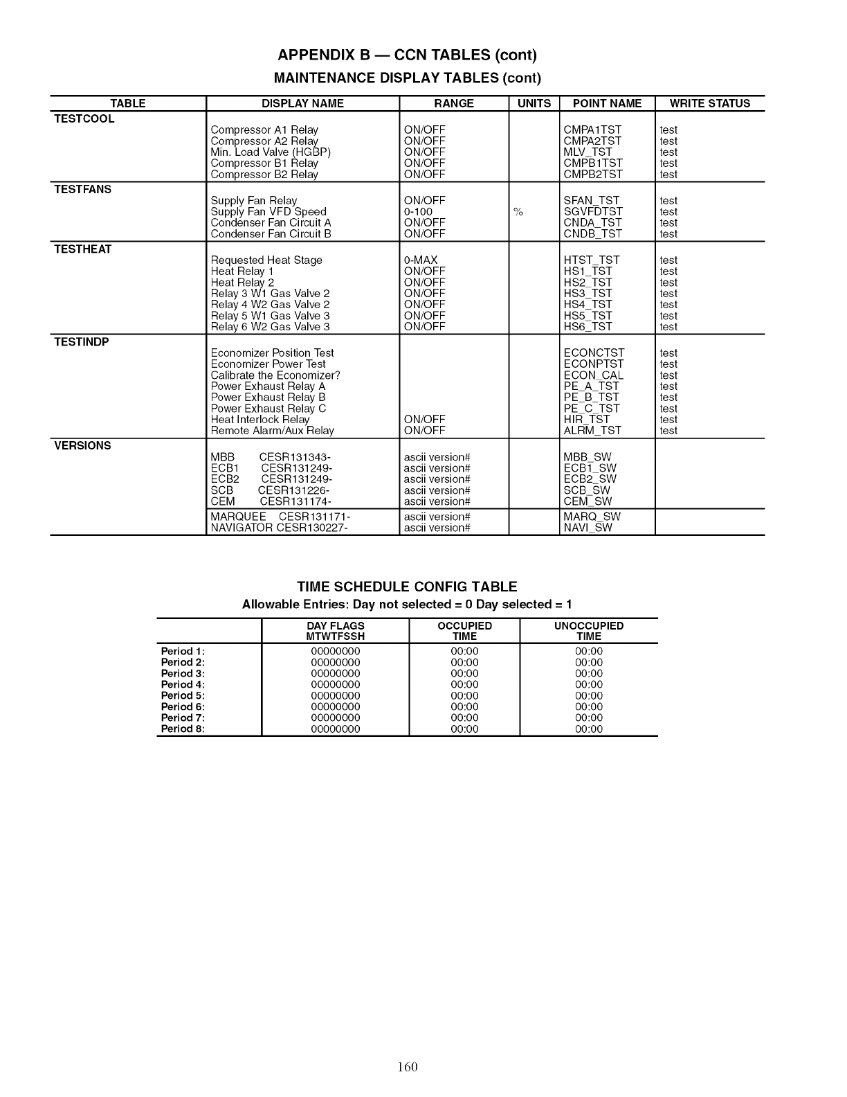
TABLE
TESTCOOL
TESTFANS
TESTHEAT
TESTINDP
VERSIONS
APPENDIX B ECON TABLES (cont)
MAINTENANCE DISPLAY TABLES (cont)
DISPLAY NAME
Compressor A1 Relay
Compressor A2 Relay
Min. Load Valve (HGBP)
Compressor B1 Relay
Compressor B2 Relay
Supply Fan Relay
Supply Fan VFD Speed
Condenser Fan Circuit A
Condenser Fan Circuit B
Requested Heat Stage
Heat Relay 1
Heat Relay 2
Relay 3 Wl Gas Valve 2
Relay 4 W2 Gas Valve 2
Relay 5 Wl Gas Valve 3
Relay 6 W2 Gas Valve 3
Economizer Position Test
Economizer Power Test
Calibrate the Economizer?
Power Exhaust Relay A
Power Exhaust Relay B
Power Exhaust Relay C
Heat Interlock Relay
Remote Alarm/Aux Relay
MBB CESR131343-
ECB1 CESR131249-
ECB2 CESR131249-
SCB CESR131226-
CEM CESR131174-
MARQUEE CESR131171-
NAVIGATOR CESR130227-
RANGE UNITS
ON/OFF
ON/OFF
ON/OFF
ON/OFF
ON/OFF
ON/OFF
0-100
ON/OFF
ON/OFF
OIMAX
ON/OFF
ON/OFF
ON/OFF
ON/OFF
ON/OFF
ON/OFF
ON/OFF
ON/OFF
ascii version#
ascii version#
ascii version#
ascii version#
ascii version#
ascii version#
ascii version#
%
POINT NAME
CMPA1TST
CMPA2TST
MLV TST
CMP-B1TST
CMPB2TST
SFAN TST
SGVF-DTST
CNDA TST
CNDB_TST
HTST TST
HS1TST
HS2TST
HS3_TST
HS4_TST
HS5 TST
HS6 TST
ECONCTST
ECONPTST
ECON CAL
PE A =I-ST
PE B TST
PE C TST
HIR TST
ALR-M TST
MBB SW
ECB1 SW
ECB2 SW
SCBSW
CEMSW
MARQ SW
NAVl SW
WRITE STATUS
test
test
test
test
test
test
test
test
test
test
test
test
test
test
test
test
test
test
test
test
test
test
test
test
Period 1:
Period 2:
Period 3:
Period 4:
Period 5:
Period 6:
Period 7:
Period 8:
TIME SCHEDULE CONFIG TABLE
Allowable Entries: Day not selected ---0 Day selected ---1
DAY FLAGS
MTWTFSSH
00000000
00000000
00000000
00000000
00000000
00000000
00000000
00000000
OCCUPIED
TIME
00:00
00:00
00:00
00:00
00:00
00:00
00:00
00:00
UNOCCUPIED
TIME
00:00
00:00
00:00
00:00
00:00
00:00
00:00
00:00
160
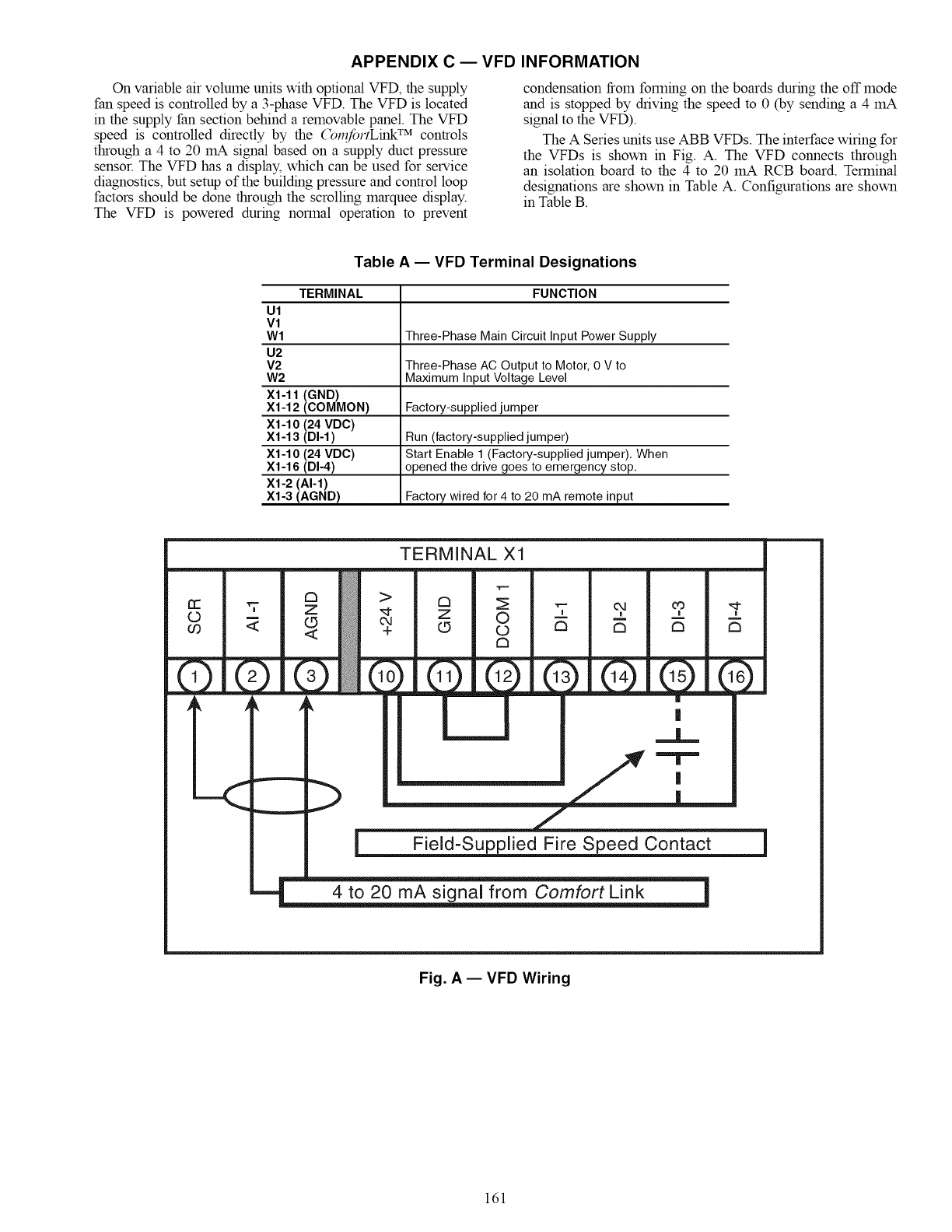
APPENDIX C EVFD INFORMATION
On variable air volume units with optional VFD, the supply
fan speed is controlled by a 3-phase VFD. The VFD is located
in the supply fan section behind a removable panel. The VFD
speed is controlled directly by the (_l_fortLink TM controls
through a 4 to 20 mA signal based on a supply duct pressure
sensor. The VFD has a display, which can be used for service
diagnostics, but setup of the building pressure and control loop
factors should be done through the scrolling marquee display.
The VFD is powered during normal operation to prevent
condensation from fonning on the boards during the off mode
and is stopped by driving the speed to 0 (by sending a 4 mA
signal to the VFD).
The A Series units use ABB VFDs. The interface wiring for
the VFDs is shown in Fig. A. The VFD connects through
an isolation board to the 4 to 20 mA RCB board. Terminal
designations are shown in Table A. Configurations are shown
in Table B.
Table A -- VFD Terminal Designations
TERMINAL FUNCTION
Ul
V1
Wl Three-Phase Main Circuit Input Power Supply
U2
V2 Three-Phase AC Output to Motor, 0 V to
W2 Maximum Input Voltage Level
X1-11 (GND)
X1-12 (COMMON) Factory-supplied jumper
X1-10 (24 VDC)
X1-13 (DI-1) Run (factory-supplied jumper)
X1-10 (24 VDC) Start Enable 1 (Factory-supplied jumper), When
X1-16 (DI-4) opened the drive goes to emergency stop,
X1-2 (AI-1)
X1-3 (AGND) Factory wired for 4 to 20 mA remote input
TERMINAL X1
©
FZEZ
lk _k _k
-->
-(.____
c3 _ '7 04 m, ,i-,
Z O -- -- -- =
L9 © C3 CI C3
Cl
[]
|
4 to 20 mA signal from Comfort Link
Fig. A -- VFD Wiring
161
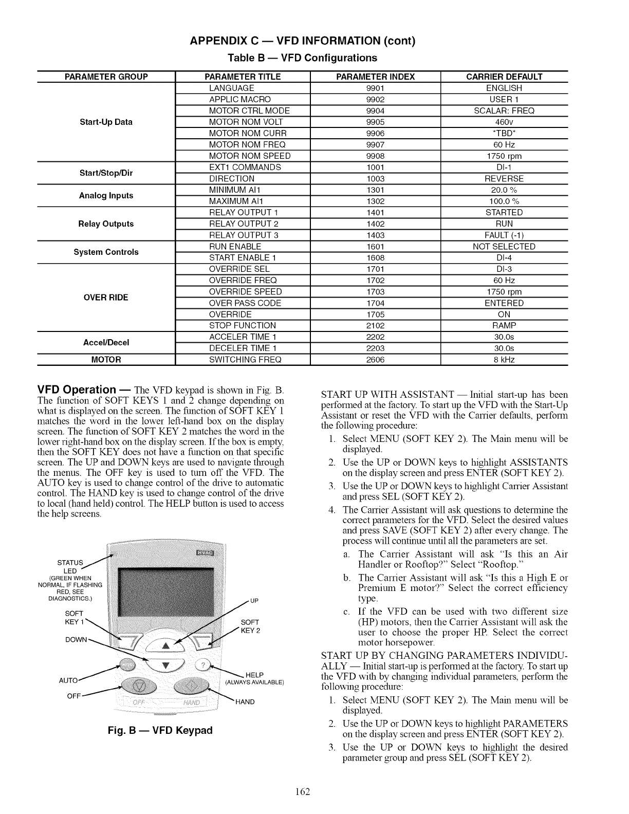
APPENDIX C EVFD INFORMATION (cont)
Table B -- VFD Configurations
PARAMETER GROUP INDEX
Start-Up Data
Start/Stop/Dir
Analog Inputs
Relay Outputs
System Controls
OVER RIDE
Accel/Decel
MOTOR
PARAMETER TITLE
LANGUAGE
APPLIC MACRO
MOTOR CTRL MODE
MOTOR NOM VOLT
MOTOR NOM CURR
MOTOR NOM FREQ
MOTOR NOM SPEED
EXT1 COMMANDS
DIRECTION
MINIMUM All
MAXIMUM All
RELAY OUTPUT 1
RELAY OUTPUT 2
RELAY OUTPUT 3
RUN ENABLE
START ENABLE 1
OVERRIDE SEL
OVERRIDE FREQ
OVERRIDE SPEED
OVER PASS CODE
OVERRIDE
STOP FUNCTION
ACCELER TIME 1
DECELER TIME 1
SWITCHING FREQ
PARAMETER
9901
9902
9904
9905
9906
9907
9908
1001
1003
1301
1302
1401
1402
1403
1601
1608
1701
1702
1703
1704
1705
2102
2202
2203
2606
CARRIER DEFAULT
ENGLISH
USER 1
SCALAR: FREQ
460v
*TBD*
60 Hz
1750 rpm
DI-1
REVERSE
20.0 %
100.0 %
STARTED
RUN
FAULT (-1)
NOT SELECTED
DI-4
DI-3
60 Hz
1750 rpm
ENTERED
ON
RAMP
30.0s
30.0s
8 kHz
VFD Operation EThe VFD keypad is shown in Fig. B.
The function of SOFT KEYS 1 and 2 change depending on
what is displayed on the screen. The function of SOFT KEY 1
matches the word in the lower left-hand box on the display
screen. The function of SOFT KEY 2 matches the word in the
lower fight-hand box on the display screen. If the box is empty,
then the SOFT KEY does not have a function on that specific
screen. The UP and DOWN keys are used to navigate through
the menus. The OFF key is used to mm off the VFD. The
AUTO key is used to change control of the drive to automatic
control. The HAND key is used to change control of the drive
to local (hand held) control. The HELP button is used to access
the help screens.
STATUS
LED
(GREEN WHEN
NORMAL, IF FLASHING
RED, SEE
DIAGNOSTICS,)
SOFT
KEY 1 SOFT
Fig. B- VFD Keypad
START UP WITH ASSISTANT -- Initial start-up has been
performed at the factory. To start up the VFD with the Start-Up
Assistant or reset the VFD with the Carrier defaults, perform
the following procedure:
1. Select MENU (SOFT KEY 2). The Main menu will be
displayed.
2. Use the UP or DOWN keys to highlight ASSISTANTS
on the display screen and press ENTER (SOFT KEY 2).
3. Use the UP or DOWN keys to highlight Carrier Assistant
and press SEL (SOFT KEY 2).
4. The Carrier Assistant will ask questions to determine the
correct parameters for the VFD. Select the desired values
and press SAVE (SOFT KEY 2) after every change. The
process will continue until all the parameters are set.
a. The Carrier Assistant will ask "Is this an Air
Handler or Rooftop?" Select "Rooftop."
b. The Carrier Assistant will ask "Is this a High E or
Premium E motor?" Select the correct efficiency
type.
c. If the VFD can be used with two different size
(HP) motors, then the Carrier Assistant will ask the
user to choose the proper HE Select the correct
motor horsepower.
START UP BY CHANGING PARAMETERS INDIVIDU-
ALLY -- Initial start-up is performed at the factory. To start up
the VFD with by changing individual parameters, perform the
following procedure:
1. Select MENU (SOFT KEY 2). The Main menu will be
displayed.
2. Use the UP or DOWN keys to highlight PARAMETERS
on the display screen and press ENTER (SOFT KEY 2).
3. Use the UP or DOWN keys to highlight the desired
parameter group and press SEL (SOFT KEY 2).
162
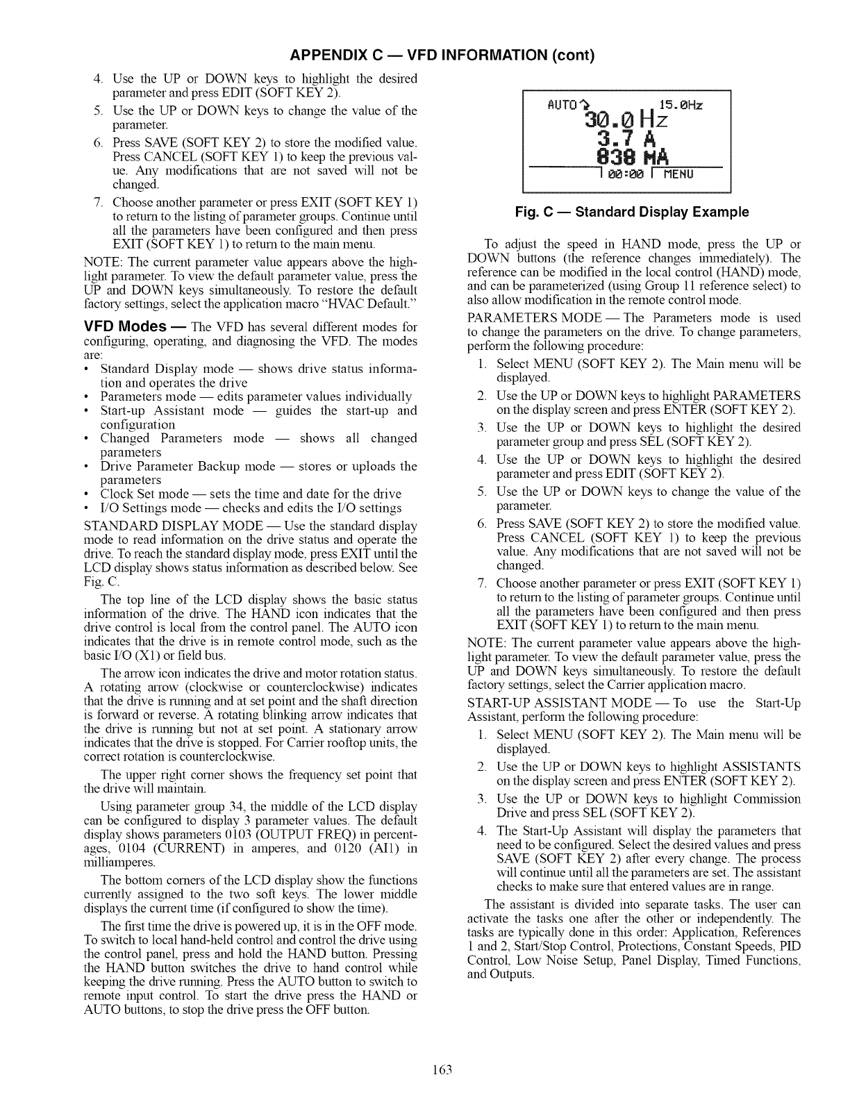
APPENDIX C EVFD INFORMATION (cont)
4. Use the UP or DOWN keys to highlight the desired
parameter and press EDIT (SOFT KEY 2).
5. Use the UP or DOWN keys to change the value of the
parameter.
6. Press SAVE (SOFT KEY 2) to store the modified value.
Press CANCEL (SOFT KEY 1) to keep the previous val-
ue. Any modifications that are not saved will not be
changed.
7. Choose another parameter or press EXIT (SOFT KEY 1)
to return to the listing of parameter groups. Continue until
all the parameters have been configured and then press
EXIT (SOFT KEY 1) to return to the main menu.
NOTE: The current parameter value appears above the high-
light parameter. To view the default parameter value, press the
UP and DOVv2',I keys shnultaneously. To restore the default
factory settings, select the application macro "HVAC Default."
VFD Modes EThe VFD has several different modes for
configuring, operating, and diagnosing the VFD. The modes
are:
• Standard Display mode -- shows drive status informa-
tion and operates the drive
• Parameters mode -- edits parameter values individually
• Start-up Assistant mode -- guides the start-up and
configuration
• Changed Parameters mode -- shows all changed
parameters
• Drive Parameter Backup mode -- stores or uploads the
parameters
• Clock Set mode -- sets the time and date for the drive
• I/O Settings mode -- checks and edits the I/O settings
STANDARD DISPLAY MODE -- Use the standard display
mode to read information on the drive stares and operate the
drive. To reach the standard display mode, press EXIT until the
LCD display shows stares information as described below. See
Fig. C.
The top line of the LCD display shows the basic status
information of the drive. The HAND icon indicates that the
drive control is local from the control panel. The AUTO icon
indicates that the drive is in remote control mode, such as the
basic I/O (X1) or field bus.
The arrow icon indicates the drive and motor rotation status.
A rotating arrow (clockwise or counterclockwise) indicates
that the drive is running and at set point and the shaft direction
is forward or reverse. A rotating blinking arrow indicates that
the drive is running but not at set point. A stationary arrow
indicates that the drive is stopped. For Carrier rooftop units, the
correct rotation is counterclockwise.
The upper right corner shows the frequency set point that
the drive will maintain.
Using parameter group 34, the middle of the LCD display
can be configured to display 3 parameter values. The default
display shows parameters 0103 (OUTPUT FREQ) in percent-
ages, 0104 (CURRENT) in amperes, and 0120 (AI1) in
milliamperes.
The bottom corners of the LCD display show the functions
currently assigned to the two soft keys. The lower middle
displays the current time (if configured to show the thne).
The first thne the drive is powered up, it is in the OFF mode.
To switch to local hand-held control and control the drive using
the control panel, press and hold the HAND button. Pressing
the HAND button switches the drive to hand control while
keeping the drive running. Press the AUTO button to switch to
remote input control. To start the drive press the HAND or
AUTO buttons, to stop the drive press the OFF button.
AUTO_ 15.0Hz
30,0 Hz
3.7A
838 MA
I 00:0o [mENU
Fig. C -- Standard Display Example
To adjust the speed in HAND mode, press the UP or
DOVV2',I buttons (the reference changes flmnediately). The
reference can be modified in the local control (HAND) mode,
and can be parameterized (using Group 11 reference select) to
also allow modification in the remote control mode.
PARAMETERS MODE- The Parameters mode is used
to change the parameters on the drive. To change parameters,
perform the following procedure:
1. Select MENU (SOFT KEY 2). The Main menu will be
displayed.
2. Use the UP or DOWN keys to highlight PARAiMETERS
on the display screen and press ENTER (SOFT KEY 2).
3. Use the UP or DOVv2',I keys to highlight the desired
parameter group and press SEL (SOFT KEY 2).
4. Use the UP or DOVv2',I keys to highlight the desired
parameter and press EDIT (SOFT KEY 2).
5. Use the UP or DOWN keys to change the value of the
parameter.
6. Press SAVE (SOFT KEY 2) to store the modified value.
Press CANCEL (SOFT KEY 1) to keep the previous
value. Any modifications that are not saved will not be
changed.
7. Choose another parameter or press EXIT (SOFT KEY 1)
to return to the listing of parameter groups. Continue until
all the parameters have been configured and then press
EXIT (SOFT KEY 1) to return to the main menu.
NOTE: The current parameter value appears above the high-
light parameter. To view the default parameter value, press the
UP and DOVv2',I keys simultaneously. To restore the default
factory settings, select the Carrier application macro.
START-UP ASSISTANT MODE -- To use the Start-Up
Assistant, perform the following procedure:
1. Select MENU (SOFT KEY 2). The Main menu will be
displayed.
2. Use the UP or DOWN keys to highlight ASSISTANTS
on the display screen and press ENTER (SOFT KEY 2).
3. Use the UP or DOWN keys to highlight Commission
Drive and press SEL (SOFT KEY 2).
4. The Start-Up Assistant will display the parameters that
need to be configured. Select the desired values and press
SAVE (SOFT KEY 2) after every change. The process
will continue until all the parameters are set. The assistant
checks to make sure that entered values are in range.
The assistant is divided into separate tasks. The user can
activate the tasks one after the other or independently. The
tasks are typically done in this order: Application, References
1 and 2, Start/Stop Control, Protections, Constant Speeds, PID
Control, Low Noise Setup, Panel Display, Thned Functions,
and Outputs.
163
APPENDIX C EVFD INFORMATION (cont)
CHANGED PARAMETERS MODE -- The Changed Param-
eters mode is used to view and edit recently changed parameters
on the drive. To view the changed parameters, perform the
following procedure:
1. Select MENU (SOFT KEY 2). The Mare menu will be
displayed.
2. Use the UP or DOWN keys to highlight CHANGED
PAR on the display screen and press ENTER (SOFT
KEY 2). A list of the recently changed parameters will be
displayed.
3. Use the UP or DOWN keys to highlight the desired pa-
rameter group and press EDIT (SOFT KEY 2) to change
the parameter if desired.
4. Press EXIT (SOFT KEY 1) to exit the Changed Parame-
ters mode.
DRIVE PARAMETER BACKUP MODE -- The drive param-
eter back up mode is used to export the parameters from one
drive to another. The parameters can be uploaded from a VFD
to the removable control panel. The control panel can then be
transferred to another drive and the parameters downloaded into
memory.
Depending on the motor and application, there are two
options available. The first option is to download all parame-
ters. This copies both application and motor parameters to the
drive from the control panel. This is recolmnended when using
the same application for drives of the same size. This can also
be used to create a backup of the parameters group for the
drive.
The second option downloads only the application parame-
ters to the drive. This is recommended when using the same ap-
plication for drives of different sizes. Parameters 9905, 9906,
9907, 9908, 9909, 1605, 1607, 5201, and group 51 parameters
and internal motor parameters are not copied.
Upload All Parameters -- To upload and store parameters in
the control panel from the VFD, perform the following
procedure:
1. Select MENU (SOFT KEY 2). The Main menu will be
displayed.
2. Use the UP or DOWN keys to highlight PAR BACKUP
on the display screen and press ENTER (SOFT KEY 2).
3. Use the UP or DOWN keys to highlight UPLOAD TO
PANEL and press SEL (SOFT KEY 2).
4. The text "Copying Parameters" will be displayed with a
progress indicator. To stop the process, select ABORT
(SOFT KEY 1).
5. When the upload is complete, the text "Parameter upload
successful" will be displayed.
6. The display will then return to the PAR BACKUP menu.
Select EXIT (SOFT KEY 1) to return to the main menu.
7. The control panel can now be disconnected from the
drive.
Download All Parameters -- To download all parameters
from the control panel to the VFD, perform the following
procedure:
1. Install the control panel with the correct parameters onto
the VFD.
2. Select MENU (SOFT KEY 2). The Mare menu will be
displayed.
3. Use the UP or DOWN keys to highlight PAR BACKUP
on the display screen and press ENTER (SOFT KEY 2).
4. Use the UP or DOWN keys to highlight DOWNLOAD
TO DRIVE ALL and press SEL (SOFT KEY 2).
5. The text "Restoring Parameters" will be displayed with a
progress indicator. To stop the process, select ABORT
(SOFT KEY 1).
6. When the download is complete, the text "Parameter
download successful" will be displayed.
7. The display will then return to the PAR BACKUP menu.
Select EXIT (SOFT KEY 1) to return to the main menu.
8. The control panel can now be disconnected from the
drive.
Download Application Parameters -- To download applica-
tion parameters only to the control panel from the VFD,
perform the following procedure:
1. Install the control panel with the correct parameters onto
the VFD.
2. Select MENU (SOFT KEY 2). The Mare menu will be
displayed.
3. Use the UP or DOWN keys to highlight PAR BACKUP
on the display screen and press ENTER (SOFT KEY 2).
4. Use the UP or DOWN keys to highlight DOWNLOAD
APPLICATION and press SEL (SOFT KEY 2).
5. The text "Downloading Parameters (partial)" will be
displayed with a progress indicator. To stop the process,
select ABORT (SOFT KEY 1).
6. When the download is complete, the text "Parameter
download successful" will be displayed.
7. The display will then return to the PAR BACKUP menu.
Select EXIT (SOFT KEY 1) to return to the main menu.
8. The control panel can now be disconnected from the
drive.
CLOCK SET MODE- The clock set mode is used for
setting the date and time for the internal clock of the VFD. In
order to use the timer functions of the VFD control, the internal
clock must be set. The date is used to determine weekdays and
is visible in the fault logs.
To set the clock, perform the following procedure:
1. Select MENU (SOFT KEY 2). The Mare menu will be
displayed.
2. Use the UP or DOWN keys to highlight CLOCK SET on
the display screen and press ENTER (SOFT KEY 2). The
clock set parameter list will be displayed.
3. Use the UP or DOWN keys to highlight CLOCK VISI-
BILITY and press SEL (SOFT KEY 2). This parameter
is used to display or hide the clock on the screen. Use the
UP or DOWN keys to change the parameter setting. Press
OK (SOFT KEY 2) to save the configuration and return
to the Clock Set menu.
4. Use the UP or DOWN keys to highlight SET TIME and
press SEL (SOFT KEY 2). Use the UP or DOWN keys to
change the hours and minutes. Press OK (SOFT KEY 2)
to save the configuration and return to the Clock Set
menu.
5. Use the UP or DOWN keys to highlightTIME FORMAT
and press SEL (SOFT KEY 2). Use the UP or DOWN
keys to change the parameter setting. Press OK (SOFT
KEY 2) to save the configuration and return to the Clock
Set menu.
6. Use the UP or DOWN keys to highlight SET DATE and
press SEL (SOFT KEY 2). Use the UP or DOWN keys to
change the day, month, and year. Press OK (SOFT KEY
2) to save the configuration and return to the Clock Set
menu.
164
APPENDIX C EVFD INFORMATION (cont)
7. Use the UP or DOWN keys to highlight DATE FOR-
MAT and press SEL (SOFT KEY 2). Use the UP or
DOWN keys to change the parameter setting. Press OK
(SOFT KEY 2) to save the configuration and return to the
Clock Set menu.
The fault code on the control panel display is temporary.
Pressing the MENU, ENTER, UP button or DOWN buttons
removes the fault message. The message reappears after a few
seconds if the control panel is not touched and the fault is still
active.
8. Press EXIT (SOFT KEY 1) twice to return to the main
menu.
I/O SETTINGS MODE -- The FO Settings mode is used for
viewing and editing the I/O settings.
To configure the I/O settings, perform the following
procedure:
1. Select MENU (SOFT KEY 2). The Main menu will be
displayed.
2. Use the UP or DOWN keys to highlight I/O SETTINGS
on the display screen and press ENTER (SOFT KEY 2).
The I/O Settings parameter list will be displayed.
3. Use the UP or DOWN keys to highlight the desired I/O
setting and press SEL (SOFT KEY 2).
4. Use the UP or DOWN keys to select the parameter to
view. Press OK (SOFT KEY 2).
5. Use the UP or DOWN keys to change the parameter
setting. Press SAVE (SOFT KEY 2) to save the configu-
ration. Press CANCEL (SOFT KEY 1) to keep the previ-
ous value. Any modifications that are not saved will not
be changed.
6. Press EXIT (SOFT KEY 1) twice to return to the main
menu.
Third Party Controls EFor conversion to third party
control of the VFD, perform the following procedure:
1. Remove the factory-installed jumper between XI-10 and
Xl-13 (control of VFD start/stop).
2. Remove the factory-installed jumper between XI-10 and
Xl-16 and replace with a normally closed safety contact
for control of VFD start enable.
3. Install speed signal wires to AI-1 and AGND. This input
is set at the factory for a 4 to 20 inN signal. If a 0 to
10 vdc signal is required, change DIP switch J1 (located
above the VFD control terminal strip) to OFF (right
position to left position) and change parameter 1301 to
0% from 20%.
VFD Diagnostics _The drive detects error situations
and reports them using:
• the green and red LEDs on the body of the drive (located
under the keypad)
• the status LED on the control panel
• the control panel display
• the Fault Word and Alarm Word parameter bits (parame-
ters 0305 to 0309)
The form of the display depends on the severity of the error.
The user can specify the severity for many errors by directing
the drive to ignore the error situation, report the situation as an
alarm, or report the situation as a fault.
FAULTS (RED LED LIT)- The VFD signals that it has
detected a severe error, or fault, by:
• enabling the red LED on the drive (LED is either steady
or flashing)
• setting an appropriate bit in a Fault Word parameter
(0305 to 0307)
• overriding the control panel display with the display of a
fault code
• stopping the motor (if it was on)
• setting an appropriate bit in Fault Word parameter 0305-
0307.
ALARMS (GREEN LED FLASHING) -- For less severe
errors, called alarms, the diagnostic display is advisory. For
these situations, the drive is simply reporting that it had detect-
ed something unusual. In these situations, the drive:
• flashes the green LED on the drive (does not apply to
alarms that arise from control panel operation errors)
• sets an appropriate bit in an Alarm Word parameter
(0308 or 0309)
• overrides the control panel display with the display of an
alarm code and/or name
Alarm messages disappear froln the control panel display
after a few seconds. The message returns periodically as long
as the alarm condition exists.
CORRECTING FAULTS -- The recommended corrective
action for faults is shown in the Fault Listing Table C. The
VFD can also be reset to remove the fault. If an external source
for a start command is selected and is active, the VFD may
start immediately after fault reset.
To reset a fault indicated by a flashing red LED, turn offthe
power for 5 minutes. To reset a fault indicated by a red LED
(not flashing), press RESET from the control panel or turn off
the power for 5 minutes. Depending on the value of parameter
1604 (FAULT RESET SELECT), digital input or serial coin-
munication could also be used to reset the drive. When the fault
has been corrected, the motor can be started.
HISTORY- For reference, the last three fault codes are
stored into parameters 0401, 0412, 0413. For the most recent
fault (identified by parameter 0401), the drive stores additional
data (in parameters 0402 through 0411) to aid in troubleshoot-
ing a problem. For example, a parameter 0404 stores the motor
speed at the time of the fault. To clear the fault history (all of
Group 04, Fault History parameters), follow these steps:
1. In the control panel, Parameters mode, select parameter
0401.
2. Press EDIT.
3. Press the UP and DOWN buttons simultaneously.
4. Press SAVE.
CORRECTING ALARMS- To correct alarms, first deter-
mine if the Alarm requires any corrective action (action is not
always required). Use Table D to find and address the root
cause of the problem.
If diagnostics troubleshooting has determined that the
drive is defective during the warranty period, contact
ABB Automation Inc., at 1-800-435-7365, option 4, option 3.
A qualified technician will review the problem with the caller
and make a determination regarding how to proceed. This may
involve dispatching a designated service station (DSS) repre-
sentative from an authorized station, dispatching a replacement
unit, or advising return for repair.
VFD Maintenance _If installed in an appropriate envi-
ronment, the VFD requires very little maintenance.
Table E lists the routine maintenance intervals recommend-
ed by Carrier.
HEAT SINK -- The heat sink fins accumulate dust from the
cooling air. Since a dusty sink is less efficient at cooling the
drive, overtemperamre faults become more likely. In a normal
environment check the heat sink annually, in a dusty environ-
ment check more often.
165
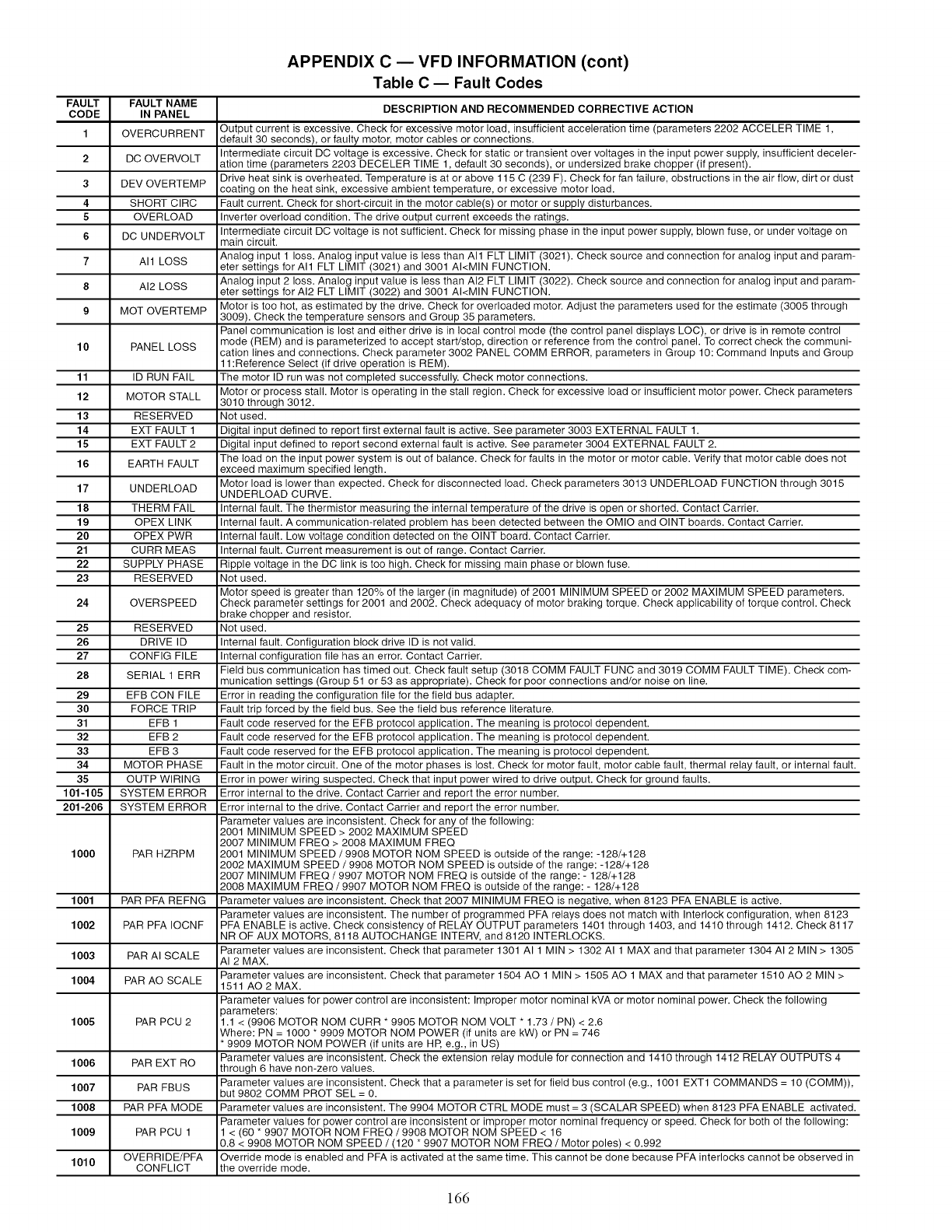
APPENDIX C EVFD INFORMATION (cont)
Table C -- Fault Codes
FAULT FAULT NAME
CODE IN PANEL DESCRIPTION AND RECOMMENDED CORRECTIVE ACTION
1 OVERCURRENT Output current is excessive. Check for excessive motor load, insufficient acceleration time (parameters 2202 ACCELER TIME 1,
default 30 seconds), or faulty motor, motor cables or connections.
Intermediate circuit DC voltage is excessive. Check for static or transient over voltages in the input power supply, insufficient deceler-
2 DC OVERVOLT ation time (parameters 2203 DECELER TIME 1, default 30 seconds), or undersized brake chopper (if present).
Drive heat sink is overheated. Temperature is at or above 115 C (239 F). Check for fan failure, obstructions in the air flow, dirt or dust
3DEV OVERTEMP coating on the heat sink, excessive ambient temperature, or excessive motor load.
4 SHORT CIRC Fault current. Check for short-circuit in the motor cable(s) or motor or supply disturbances.
5OVERLOAD Inverter overload condition. The drive output current exceeds the ratings.
6DC UNDERVOLT Intermediate circuit DC voltage is not sufficient. Check for missing phase in the input power supply, blown fuse, or under voltage on
main circuit.
Analog input 1 loss. Analog input value is less than All FLT LIMIT (3021). Check source and connection for analog input and param-
7 All LOSS eter settings for All FLT LIMIT (3021) and 3001 AI<MIN FUNCTION.
Analog input 2 loss. Analog input value is less than AI2 FLT LIMIT (3022). Check source and connection for analog input and param-
8AI2 LOSS eter settings for AI2 FLT LIMIT (3022) and 3001 AI<MIN FUNCTION.
9 MOT OVERTEMP Motor is too hot, as estimated by the drive. Check for overloaded motor. Adjust the parameters used for the estimate (3005 through
3009). Check the temperature sensors and Group 35 parameters.
Panel communication is lost and either drive is in local control mode (the control panel displays LOC), or drive is in remote control
10 PANEL LOSS mode (REM) and is parameterized to accept start/stop, direction or reference from the control panel. To correct check the communi-
cation lines and connections. Check parameter 3002 PANEL COMM ERROR, parameters in Group 10: Command Inputs and Group
1:Reference Select (if drive operation is REM).
11 ID RUN FAIL The motor ID run was not completed successfully. Check motor connections.
12 MOTOR STALL Motor or process stall. Motor is operating in the stall region. Check for excessive load or insufficient motor power. Check parameters
3010 through 3012.
13 RESERVED Not used.
14 EXT FAULT 1 Digital input defined to report first external fault is active. See parameter 3003 EXTERNAL FAULT 1.
15 EXT FAULT 2 Digital input defined to report second external fault is active. See parameter 3004 EXTERNAL FAULT 2.
The load on the input power system is out of balance. Check for faults in the motor or motor cable. Verify that motor cable does not
16 EARTH FAULT exceed maximum specified length.
17 UNDERLOAD Motor load is lower than expected. Check for disconnected load. Check parameters 3013 UNDERLOAD FUNCTION through 3015
UNDERLOAD CURVE.
18 THERM FAIL Internal fault. The thermistor measuring the internal temperature of the drive is open or shorted. Contact Carrier.
19 OPEX LINK Internal fault. A communication-related problem has been detected between the OMIO and OINT boards. Contact Carrier.
20 OPEX PWR Internal fault. Low voltage condition detected on the OINT board. Contact Carrier.
21 CURR MEAS Internal fault. Current measurement is out of range. Contact Carrier.
22 SUPPLY PHASE Ripple voltage in the DC link is too high. Check for missing main phase or blown fuse.
23 RESERVED Not used.
Motor speed is greater than 120% of the larger (in magnitude) of 2001 MINIMUM SPEED or 2002 MAXIMUM SPEED parameters.
24 OVERSPEED Check parameter settings for 2001 and 2002. Check adequacy of motor braking torque. Check applicability of torque control. Check
brake chopper and resistor.
25 RESERVED Not used.
26 DRIVE ID Internal fault. Configuration block drive ID is not valid.
27 CONFIG FILE Internal configuration file has an error. Contact Carrier.
28 SERIAL 1 ERR Field bus communication has timed out. Check fault setup (3018 COMM FAULT FUNC and 3019 COMM FAULT TIME). Check com-
munication settings (Group 51 or 53 as appropriate). Check for poor connections and/or noise on line.
29 EFB CON FILE Error in reading the configuration file for the field bus adapter.
30 FORCE TRIP Fault trip forced by the field bus. See the field bus reference literature.
31 EFB 1 Fault code reserved for the EFB protocol application. The meaning is protocol dependent.
32 EFB 2 Fault code reserved for the EFB protocol application. The meaning is protocol dependent.
33 EFB 3 Fault code reserved for the EFB protocol application. The meaning is protocol dependent.
34 MOTOR PHASE Fault in the motor circuit. One of the motor phases is lost. Check for motor fault, motor cable fault, thermal relay fault, or internal fault.
35 OUTP WIRING Error in power wiring suspected. Check that input power wired to drive output. Check for ground faults.
101-105 SYSTEM ERROR Error internal to the drive. Contact Carrier and report the error number.
201-206 SYSTEM ERROR Error internal to the drive. Contact Carrier and report the error number.
Parameter values are inconsistent. Check for any of the following:
2001 MINIMUM SPEED > 2002 MAXIMUM SPEED
2007 MINIMUM FREQ > 2008 MAXIMUM FREQ
1000 PAR HZRPM 2001 MINIMUM SPEED /9908 MOTOR NOM SPEED is outside of the range: -128/+128
2002 MAXIMUM SPEED /9908 MOTOR NOM SPEED is outside of the range: -128/+128
2007 MINIMUM FREQ /9907 MOTOR NOM FREQ is outside of the range: - 128/+128
2008 MAXIMUM FREQ /9907 MOTOR NOM FREQ is outside of the range: - 128/+128
1001 PAR PFA REFNG Parameter values are inconsistent. Check that 2007 MINIMUM FREQ is negative, when 8123 PFA ENABLE is active.
Parameter values are inconsistent. The number of programmed PFA relays does not match with Interlock configuration, when 8123
1002 PAR PFA IOCNF PFA ENABLE is active. Check consistency of RELAY OUTPUT parameters 1401 through 1403, and 1410 through 1412. Check 8117
NR OF AUX MOTORS, 8118 AUTOCHANGE INTERV, and 8120 INTERLOCKS.
Parameter values are inconsistent. Check that parameter 1301 AI 1 MIN > 1302 AI 1 MAX and that parameter 1304 AI 2 MIN > 1305
1003 PAR AI SCALE AI 2 MAX.
1004 PAR AO SCALE Parameter values are inconsistent. Check that parameter 1504 AO 1 MIN > 1505 AO 1 MAX and that parameter 1510 AO 2 MIN >
1511 AO2 MAX.
Parameter values for power control are inconsistent: Improper motor nominal kVA or motor nominal power. Check the following
parameters:
1005 PARPCU2 1.1<(9906MOTORNOMCURR*9905MOTORNOMVOLT*1.73/PN)<2.6
Where: PN = 1000 * 9909 MOTOR NOM POWER (if units are kW) or PN = 746
• 9909 MOTOR NOM POWER (if units are HP, e.g., in US)
Parameter values are inconsistent. Check the extension relay module for connection and 1410 through 1412 RELAY OUTPUTS 4
1006 PAR EXT RO through 6 have non-zero values.
Parameter values are inconsistent. Check that a parameter is set for field bus control (e.g., 1001 EXT1 COMMANDS = 10 (COMM)),
1007 PAR FBUS but 9802 COMM PROT SEL = 0.
1008 PAR PFA MODE Parameter values are inconsistent. The 9904 MOTOR CTRL MODE must = 3 (SCALAR SPEED) when 8123 PFA ENABLE activated.
Parameter values for power control are inconsistent or improper motor nominal frequency or speed. Check for both of the following:
1009 PAR PCU 1 < (60 * 9907 MOTOR NOM FREQ /9908 MOTOR NOM SPEED < 16
0.8 < 9908 MOTOR NOM SPEED /(120 * 9907 MOTOR NOM FREQ /Motor poles) < 0.992
1010 OVERRIDE/PFA Override mode is enabled and PFA is activated at the same time. This cannot be done because PFA interlocks cannot be observed in
CONFLICT the override mode.
166
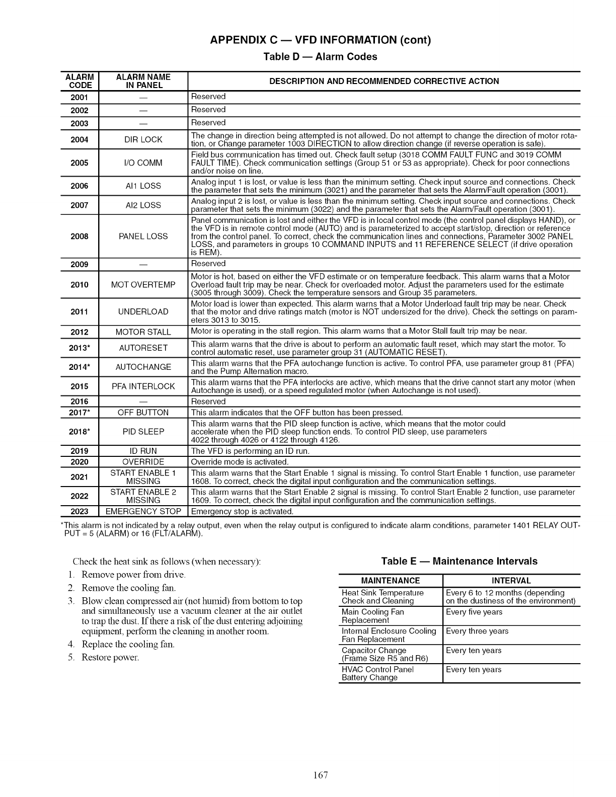
APPENDIX C EVFD INFORMATION (cont)
Table D -- Alarm Codes
ALARM ALARM NAME DESCRIPTION AND RECOMMENDED CORRECTIVE ACTION
CODE IN PANEL
2001 -- Reserved
2002 -- Reserved
2003 -- Reserved
The change in direction being attempted is not allowed, Do not attempt to change the direction of motor rota-
2004 DIR LOCK tion, or Change parameter 1003 DIRECTION to allow direction change (if reverse operation is safe),
Field bus communication has timed out, Check fault setup (3018 COMM FAULT FUNC and 3019 COMM
2005 I/O COMM FAULT TIME), Check communication settings (Group 51 or 53 as appropriate), Check for poor connections
and/or noise on line,
2006 All LOSS Analog input 1 is lost, or value is less than the minimum setting, Check input source and connections, Check
the parameter that sets the minimum (3021) and the parameter that sets the Alarm/Fault operation (3001),
2007 AI2 LOSS Analog input 2 is lost, or value is less than the minimum setting, Check input source and connections, Check
parameter that sets the minimum (3022) and the parameter that sets the Alarm/Fault operation (3001),
Panel communication is lost and either the VFD is in local control mode (the control panel displays HAND), or
the VFD is in remote control mode (AUTO) and is parameterized to accept start/stop, direction or reference
2008 PANEL LOSS from the control panel, To correct, check the communication lines and connections, Parameter 3002 PANEL
LOSS, and parameters in groups 10 COMMAND INPUTS and 11 REFERENCE SELECT (if drive operation
is REM),
2009 -- Reserved
Motor is hot, based on either the VFD estimate or on temperature feedback, This alarm warns that a Motor
2010 MOT OVERTEMP Overload fault trip may be near, Check for overloaded motor, Adjust the parameters used for the estimate
(3005 through 3009), Check the temperature sensors and Group 35 parameters,
Motor load is lower than expected, This alarm warns that a Motor Underload fault trip may be near, Check
2011 UNDERLOAD that the motor and drive ratings match (motor is NOT undersized for the drive), Check the settings on param-
eters 3013 to 3015,
2012 MOTOR STALL Motor is operating in the stall region, This alarm warns that a Motor Stall fault trip may be near,
This alarm warns that the drive is about to perform an automatic fault reset, which may start the motor, To
2013" AUTORESET control automatic reset, use parameter group 31 (AUTOMATIC RESET),
This alarm warns that the PFA autochange function is active, To control PFA, use parameter group 81 (PFA)
2014" AUTOCHANGE and the Pump Alternation macro,
This alarm warns that the PFA interlocks are active, which means that the drive cannot start any motor (when
2015 PFA INTERLOCK Autochange is used), or a speed regulated motor (when Autochange is not used),
2016 -- Reserved
2017" OFF BUTTON This alarm indicates that the OFF button has been pressed,
This alarm warns that the PID sleep function is active, which means that the motor could
2018" PID SLEEP accelerate when the PID sleep function ends, To control PID sleep, use parameters
4022 through 4026 or 4122 through 4126,
2019 ID RUN The VFD is performing an ID run,
2020 OVERRIDE Override mode is activated,
START ENABLE 1 This alarm warns that the Start Enable 1 signal is missing, To control Start Enable 1 function, use parameter
2021 MISSING 1608, To correct, check the digital input configuration and the communication settings,
START ENABLE 2 This alarm warns that the Start Enable 2 signal is missing, To control Start Enable 2 function, use parameter
2022 MISSING 1609, To correct, check the digital input configuration and the communication settings,
2023 EMERGENCY STOP Emergency stop is activated,
*This alarm is not indicated by a relay output, even when the relay output is configured to indicate alarm conditions, parameter 1401 RELAY OUT-
PUT = 5 (ALARM) or 16 (FLT/ALARM),
Check the heat sink as follows (when necessary):
1. Remove power from drive.
2. Remove the cooling fan.
3. Blow clean compressed air (not humid) from bottom to top
and shnultaneously use a vacuum cleaner at the air outlet
to trap the dust. If there a risk of the dust entering adjoining
equipment, perform the cleaning in another room.
4. Replace the cooling fan.
5. Restore power.
Table E-- Maintenance Intervals
MAINTENANCE INTERVAL
Heat Sink Temperature Every 6 to 12 months (depending
Check and Cleaning on the dustiness of the environment)
Main Cooling Fan Every five years
Replacement
Internal Enclosure Cooling Every three years
Fan Replacement
Capacitor Change Every ten years
(Frame Size R5 and R6)
HVAC Control Panel Every ten years
Battery Change
167
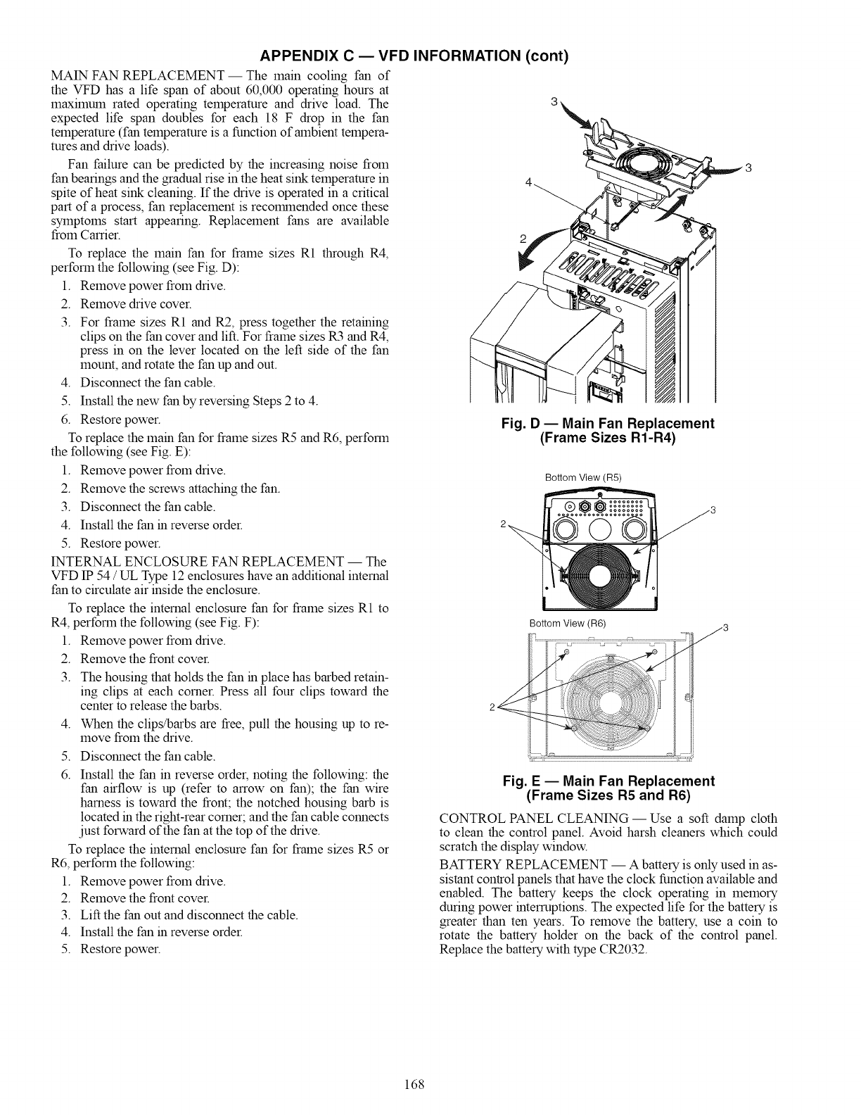
APPENDIX C EVFD INFORMATION (cont)
MAIN FAN REPLACEMENT- The main cooling fan of
the VFD has a life span of about 60,000 operating hours at
maximum rated operating temperature and drive load. The
expected life span doubles for each 18 F drop in the fan
temperature (fan temperature is a function of ambient tempera-
tures and drive loads).
Fan failure can be predicted by the increasing noise from
fan bearings and the gradual rise in the heat sink temperature in
spite of heat sink cleaning. If the drive is operated in a critical
part of a process, fan replacement is recolrnnended once these
symptolns start appearing. Replacement fans are available
from Carrier.
To replace the main fan for flame sizes R1 through R4,
perform the following (see Fig. D):
1. Remove power from drive.
2. Remove drive cover.
3. For flame sizes R1 and R2, press together the retaining
clips on the fan cover and lift. For frame sizes R3 and R4,
press in on the lever located on the left side of the fan
mount, and rotate the fan up and out.
4. Disconnect the fan cable.
5. Install the new fan by reversing Steps 2 to 4.
6. Restore power.
To replace the main fan for frame sizes R5 and R6, perform
the following (see Fig. E):
1. Remove power from drive.
2. Remove the screws attaching the fan.
3. Disconnect the fan cable.
Fig. D -- Main Fan Replacement
(Frame Sizes R1-R4)
Bottom View (R5)
4. Install the fan in reverse order.
5. Restore power.
INTERNAL ENCLOSURE FAN REPLACEMENT -- The
VFD IP 54 /UL Type 12 enclosures have an additional internal
fan to circulate air inside the enclosure.
To replace the internal enclosure fan for frame sizes R1 to
R4, perform the following (see Fig. F):
1. Remove power from drive.
2. Remove the front cover.
3. The housing that holds the fan in place has barbed retain-
ing clips at each corner. Press all four clips toward the
center to release the barbs.
4. When the clips/barbs are free, pull the housing up to re-
move from the drive.
5. Disconnect the fan cable.
6. Install the fan in reverse order, noting the following: the
fan airflow is up (refer to arrow on fan); the fan wire
harness is toward the front; the notched housing barb is
located in the right-rear corner; and the fan cable connects
.just forward of the fan at the top of the drive.
To replace the internal enclosure fan for flame sizes R5 or
R6, perform the following:
1. Remove power from drive.
2. Remove the front cover.
3. Lift the fan out and disconnect the cable.
4. Install the fan in reverse order.
5. Restore power.
Bottom View (R6)
................................................................._Y _3
Fig. E -- Main Fan Replacement
(Frame Sizes R5 and R6)
CONTROL PANEL CLEANING- Use a soft damp cloth
to clean the control panel. Avoid harsh cleaners which could
scratch the display window.
BATTERY REPLACEMENT -- A battery is only used in as-
sistant control panels that have the clock function available and
enabled. The battery keeps the clock operating in memory
during power interruptions. The expected life for the battery is
greater than ten years. To remove the battery, use a coin to
rotate the battery holder on the back of the control panel.
Replace the battery with type CR2032.
168
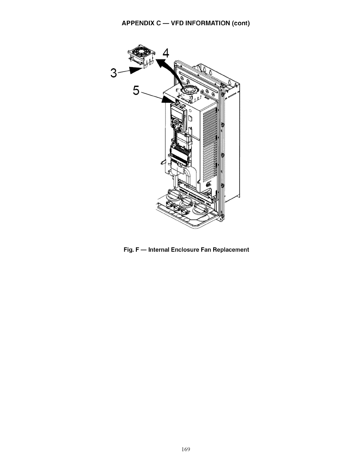
APPENDIX C EVFD INFORMATION (cont)
3
5
4
Fig. F- Internal Enclosure Fan Replacement
169
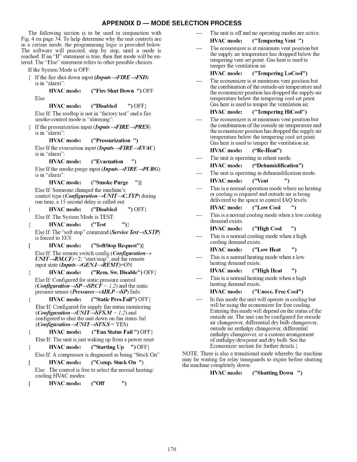
APPENDIX D EMODE SELECTION PROCESS
The following section is to be used in conjunction with
Fig. 4 on page 34. To help determine why the unit controls are
in a certain mode, the progralmning logic is provided below.
The software will proceed, step by step, until a mode is
reached. If an "If" statement is true, then that mode will be en-
tered. The "Else" statement refers to other possible choices.
If the System Mode is OFF:
{ If the fire shut down input (Inputs'--cFIRE-cFSD)
is in "alarm":
HVAC mode: ("Fire Shut Down ") OFF
Else
HVAC mode: ("Disabled ") OFF}
Else If: The rooftop is not in "factory test" and a fire
smoke-control mode is "alarming":
{ If the pressurization input (Inputs'--+FIRE--+PRES)
is in "alarm":
HVAC mode: ("Pressurization ")
Else If the evacuation input (Inputs-+FIRE-+EVAO
is in "alarm":
HVAC mode: ("Evacuation ")
Else If the smoke purge input (Inputs'--+FIRE--+PURG)
is in "alarm":
HVAC mode: ("Smoke Purge ")}
Else If: Someone changed the machine's
control type (Configuration-+UNIr_: TYP) during
run time, a 15 second delay is called out:
{ HVAC mode: ("Disabled ") OFF}
Else If: The System Mode is TEST:
{ HVAC mode: ("Test ")}
Else If: The "soft stop" colmnand (Service Test-+S.STP)
is forced to YES:
{ HVAC mode: ("SoftStop Request")}
Else If: The remote switch config (Configuration--+
UNIT-+RM. CF) 2; "start/stop", and the remote
input state (Inputs-+GEN.I-+REMT)=ON:
{ HVAC mode: ("Rein. Sw. Disable") OFF}
Else If: Configured for static pressure control
(Configuration---_SP---_SR CF 1, 2) and the static
pressure sensor (Pressures-+AIR.P--+SP) fails:
{ HVAC mode: ("Static Pres.Fail") OFF}
Else If: Configured for supply fan status monitoring
(Configuration-cUNIT--)SFS.M 1,2) and
configured to shut the unit down on fan status fail
((bnfiguration--+UNIT--+SFS.S = YES)
{ HVAC mode: ("Fan Status Fail ") OFF}
Else If: The unit is just waking up from a power reset
{ HVAC mode: ("Starting Up ") OFF}
Else If: Acompressor is diagnosed as being "Stuck On"
{HVAC mode: ("Comp. Stuck On ")
Else The control is free to select the normal heating/
cooling HVAC modes:
{HVAC mode: ("Off ")
-- The unit is off and no operating modes are active.
HVAC mode: ("Tempering Vent ")
-- The economizer is at minimum vent position but
the supply air temperature has dropped below the
tempering vent set point. Gas heat is used to
temper the ventilation air.
HVAC mode: ("Tempering LoCool")
-- The economizer is at minflnum vent position but
the combination of the outside-air temperature and
the economizer position has dropped the supply-air
temperature below the tempering cool set point.
Gas heat is used to temper the ventilation air.
HVAC mode: ("Tempering HiCool")
-- The economizer is at minimum vent position but
the combination of the outside air temperature and
the economizer position has dropped the supply air
temperature below the tempering cool set point.
Gas heat is used to temper the ventilation air.
HVAC mode: ("Re-Heat")
-- The unit is operating in reheat mode.
HVAC mode: ("Dehumidification")
-- The unit is operating in dehumidification mode.
HVAC mode: ("Vent ")
-- This is a normal operation mode where no heating
or cooling is required and outside air is being
delivered to the space to control IAQ levels.
HVAC mode: ("Low Cool ")
-- This is a normal cooling mode when a low cooling
demand exists.
HVAC mode: ("High Cool ")
-- This is anormal cooling mode when a high
cooling demand exists.
HVAC mode: ("Low Heat ")
-- This is a normal heating mode when a low
heating demand exists.
HVAC mode: ("High Heat ")
-- This is a normal heating mode when a high
heating demand exists.
HVAC mode: ("Unoee. Free Cool")
-- In this mode the unit will operate in cooling but
will be using the economizer for free cooling.
Entering this mode will depend on the status of the
outside air. The unit can be configured for outside
air changeover, differential dry bulb changeover,
outside air enthalpy changeover, differential
enthalpy changeover, or a custom arrangement
of enthalpy/dewpoint and dry bulb. See the
Economizer section for further details.}
NOTE: There is also a transitional mode whereby the machine
may be waiting for relay timeguards to expire before shutting
the machine completely down:
HVAC mode: ("Shutting Down ")
170
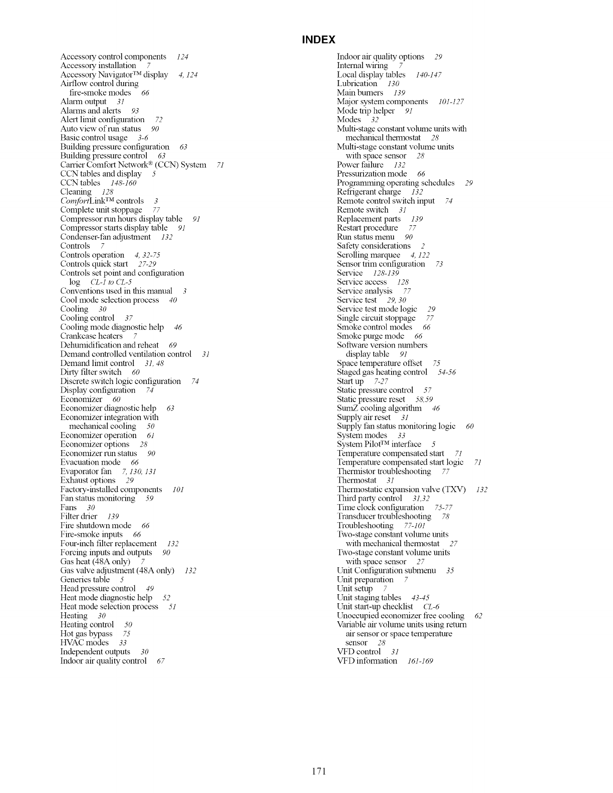
Accessorycontrolcomponents124
Accessory installation 7
Accessory Navigator TM display 4, 124
Airflow control during
fire-smoke modes 66
Alarm output 31
Alarms and alerts 93
Alert limit configuration 72
Auto view of run status 90
Basic control usage 3-6
Buikling pressure contiguration 63
Building pressure control 63
Carrier Comfort Network _v(CCN) System
CCN tables and display 5
CCN tables 148-160
Cleaning 126'
(bmJortLink TM controls 3
Complete unit stoppage 77
Compressor run hours display table 91
Compressor starts display table 91
Condenser-fan adjustment 132
Controls 7
Controls operation 4, 32-75
Controls quick start 27-29
Controls set point and configuration
log (Z-1 to (Z-5
Conventions used in this manual 3
Cool mode selection process 40
Cooling 30
Cooling control 37
Cooling mode diagnostic help 46
Crankcase heaters 7
Dehumidification and reheat 69
Demand controlled ventilation control 31
Demand limit control 31,48
Dirty filter switch 60
Discrete switch logic configuration 74
Display configuration 74
Economizer 60
Economizer diagnostic help 63
Economizer integration with
mechanical cooling 50
Economizer operation 61
Economizer options 28
Economizer run status 90
Evacuation mode 66
Evaporator t:an 7,130,13l
Exhaust options 29
Factory-installed components 101
Fan status monitoring 59
Fans 30
Filter drier 139
Fire shutdown mode 66
Fire-smoke inputs 66
Four-inch filter replacement 132
Forcing inputs and outputs 90
Gas heat (48A only) 7
Gas valve adjustment (48A only) 132
Generics table 5
Head pressure control 49
Heat mode diagnostic help 52
Heat mode selection process 51
Heating 30
Heating control 50
Hot gas bypass 75
HVAC modes 33
Independent outputs 30
Indoor air quality control 67
71
INDEX
Indoor air quality options 29
Internal wiring 7
Local display tables 140-147
Lubrication 130
Main burners 139
Major system components 101-127
Mode trip helper 91
Modes 32
Multi-stage constant volume units with
mechanical thermostat 28
Multi-stage constant volume units
with space sensor 28
Power thilure 132
Pressurization mode 66
Programming operating schedules 29
Refrigerant charge 132
Remote control switch input 74
Remote switch 31
Replacement parts 139
Restart procedure 77
Run status menu 90
Safety considerations 2
Scrolling marquee 4, 122
Sensor trim configuration 73
Service 128-139
Service access 126'
Service analysis 77
Service test 29, 30
Service test mode logic 29
Single circuit stoppage 77
Smoke control modes 66
Smoke purge mode 66
Software version numbers
display table 91
Space temperature ofi_et 75
Staged gas heating control 54-56
Start up 7-27
Static pressure control 57
Static pressure reset 58,59
SumZ cooling algorithm 46
Supply air reset 31
Supply tan status monitoring logic 60
System modes 33
System Piloff M interface 5
Temperature compensated start 71
Temperature compensated start logic
Thermistor troubleshooting 77
Thermostat 31
Thermostatic expansion valve (TXV)
Third party control 31,32
Time clock configuration 75-77
Transducer troubleshooting 76'
Troubleshooting 77-101
Two-stage constant volume units
with mechanical thermostat 27
Two-stage constant volume units
with space sensor 27
Unit Cont]guration submenu 35
Unit preparation 7
Unit setup 7
Unit staging tables 43-45
Unit start-up checklist CZ-6
Unoccupied economizer tree cooling
Variable air volume units using return
air sensor or space temperature
sensor 28
VFD control 31
VFD information 161-169
71
132
62
171

Copyright 2008 Carrier Corporation
Manufacturer reserves the right to discontinue, or change at any time, specifications or designs without notice and without incurring obligations.
Catalog No. 04-53480050-01 Printed in U.S.A. Form 48/50A-7T Pg 172 5-08 Replaces: 48/50A-6T
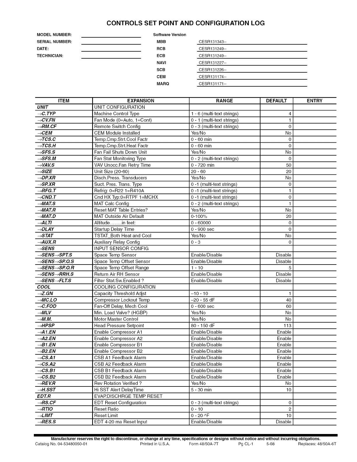
MODEL NUMBER:
SERIAL NUMBER:
DATE:
TECHNICIAN:
CONTROLS SET POINT AND CONFIGURATION LOG
Software Version
MBB CESR131343--
RCB CESR131249--
ECB CESR131249--
NAVI CESR131227--
SCB CESR131226--
CEM CESR131174--
MARQ CESR131171--
ITEM EXPANSION RANGE DEFAULT ENTRY
UNIT UNIT CONFIGURATION
-_C.TYP Machine Control Type 1 - 6 (multi-text strings) 4
-_CV.FN Fan Mode (O=Auto, l=Cont) 0 - 1 (multi-text strings) 1
-_RM.CF Remote Switch Config 0 -3 (multi-text strings) 0
-_CEM CEM Module Installed Yes/No No
-_TCS.C Temp.Cmp.Strt.Cool Factr 0 - 60 min 0
-_TCS.H Temp.Cmp.Strt.Heat Factr 0 - 60 min 0
-_SFS.S Fan Fail Shuts Down Unit Yes/No No
-_SFS.M Fan Stat Monitoring Type 0 - 2 (multi-text strings) 0
-_VAV.S VAV Unocc.Fan Retry Time 0 - 720 min 50
-_SlZE Unit Size (20-60) 20 - 60 20
-_DP.XR Disch.Press. Transducers Yes/No No
-_SP.XR Suct. Pres. Trans. Type 0 -1 (multi-text strings) 0
-_RFG.T Refrig: 0=R22 1=R410A 0 -1 (multi-text strings) 1
-_CND.T Cnd HX Typ:O=RTPF I=MCHX 0 -1 (multi-text strings) 0
-_MAT.S MAT Calc Config 0 - 2 (multi-text strings) 1
-_MAT.R Reset MAT Table Entries? Yes/No No
-_MAT.D MAT Outside Air Default 0-100% 20
-_ALTI Altitude ........ in feet: 0 - 60000 0
-_DLAY Startup Delay Time 0 - 900 sec 0
-_STAT TSTAT_Both Heat and Cool Yes/No No
-_AUX.R Auxiliary Relay Config 0 - 3 0
-_SENS INPUT SENSOR CONFIG
-_SENS-_SPT.S Space Temp Sensor Enable/Disable Disable
-_SENS-_SP.O.S Space Temp Offset Sensor Enable/Disable Disable
-_SENS-_SP.O.R Space Temp Offset Range 1 - 10 5
-_SENS-_RRH.S Return Air RH Sensor Enable/Disable Disable
-_SENS-_FLT.S Filter Stat.Sw.Enabled ? Enable/Disable Disable
COOL COOLING CONFIGURATION
-_Z.GN Capacity Threshold Adjst -10 - 10 1
-_MC.LO Compressor Lockout Temp -20 - 55 dF 40
-_C.FOD Fan-Off Delay, Mech Cool 0 - 600 sec 60
-_MLV Min. Load Valve? (HGBP) Yes/No No
-_M.M. Motor Master Control Yes/No No
-_HPSP Head Pressure Setpoint 80 - 150 d F 113
-_A I.EN Enable Compressor A1 Enable/Disable Enable
-_A2.EN Enable Compressor A2 Enable/Disable Enable
-_BI.EN Enable Compressor B1 Enable/Disable Enable
-_B2.EN Enable Compressor B2 Enable/Disable Enable
-_CS.A ICSB A1 Feedback Alarm Enable/Disable Enable
-_CS.A2 CSB A2 Feedback Alarm Enable/Disable Enable
-_CS.BI CSB B1 Feedback Alarm Enable/Disable Enable
-_CS.B2 CSB B2 Feedback Alarm Enable/Disable Enable
-_REV.R Rev Rotation Verified ? Yes/No No
-_H.SST Hi SST Alert DelayTime 5 - 30 min 10
EDT.R EVARDISCHRGE TEMP RESET
-_RS.CF EDT Reset Configuration 0 - 3 (multi-text strings) 0
-_RTIO Reset Ratio 0 - 10 2
-_LIMT Reset Limit 0 - 20 ^F 10
-_RES.S EDT 4-20 ma Reset Input Enable/Disable Disable
Manufacturer reserves the right to discontinue, or change at any time, specifications or designs without notice and without incurring obligations.
Catalog No. 04-53480050-01 Printed in U.S.A. Form 48/50A-7T Pg CL-1 5-08 Replaces: 48/50A-6T
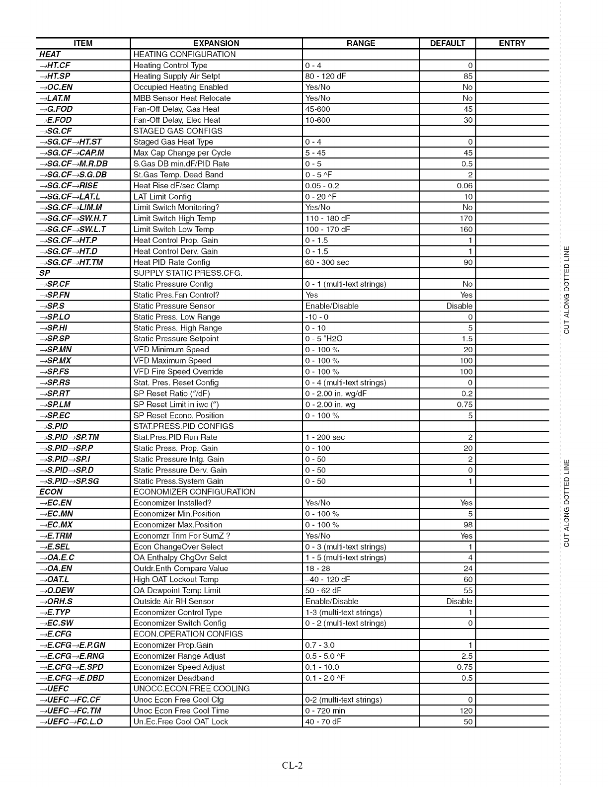
ITEM EXPANSION RANGE DEFAULT ENTRY
HEAT HEATING CONFIGURATION
-_HT.CF Heating Control Type 0 - 4 0
-_HT.SP Heating Supply Air Setpt 80 - 120 dF 85
-,OC.EN Occupied Heating Enabled Yes/No No
-_LAT.M MBB Sensor Heat Relocate Yes/No No
-,G.FOD Fan-Off Delay, Gas Heat 45-600 45
-_E.FOD Fan-Off Delay, Elec Heat 10-600 30
-_SG.CF STAGED GAS CONFIGS
-_SG.CF-,HT.ST Staged Gas Heat Type 0 - 4 0
-_SG.CF-,CAP.M Max Cap Change per Cycle 5 - 45 45
-_SG.CF-,M.R.DB S,Gas DB min,dF/PID Rate 0 - 5 0,5
-_SG.CF-,S.G.DB St,Gas Temp, Dead Band 0 - 5 ^F 2
-_SG.CF-,RISE Heat Rise dF/sec Clamp 0,05 - 0,2 0,06
-_SG.CF-,LAT.L LAT Limit Config 0 - 20 ^F 10
-_SG.CF-,LIM.M Limit Switch Monitoring? Yes/No No
-_SG.CF-,SW.H.T Limit Switch High Temp 110 - 180 dF 170
-_SG. CF-,SW.L. T Limit Switch Low Temp 1O0 - 170 dF 160
-_SG.CF-,HT.P Heat Control Prop, Gain 0 - 1,5 1
-_SG.CF-,HT.D Heat Control Derv, Gain 0 - 1,5 1
-_SG.CF-,HT.TM Heat PID Rate Config 60 - 300 sec 90
SP SUPPLY STATIC PRESS,CFG,
-_SP.CF Static Pressure Config 0 - 1 (multi-text strings) No
-_SP.FN Static Pres,Fan Control? Yes Yes
-_SP.S Static Pressure Sensor Enable/Disable Disable
-_SP.LO Static Press, Low Range -10 - 0 0
-_SP.HI Static Press, High Range 0 - 10 5
-_SP.SP Static Pressure Setpoint 0 - 5 "H20 1,5
-_SP.MN VFD Minimum Speed 0 - 100 % 20
-_SP.MX VFD Maximum Speed 0 - 100 % 100
-_SP.FS VFD Fire Speed Override 0 - 100 % 100
-_SP.RS Stat, Pres, Reset Config 0 - 4 (multi-text strings) 0
-_SP.RT SP Reset Ratio ("/dF) 0 - 2,00 in, wg/dF 0,2
-_SP.LM SP Reset Limit in iwc (") 0 - 2,00 in, wg 0,75
-_SP.EC SP Reset Econo, Position 0 - 100 % 5
-_S.PID STAT.PR ESS,PID CONFIGS
-_S.PID-,SP.TM Stat,Pres,PID Run Rate 1 - 200 sec 2
-_S.PID-,SP.P Static Press, Prop, Gain 0 - 100 20
-_S.PID-,SP.I Static Pressure Intg, Gain 0 - 50 2
-_S.PID-,SP.D Static Pressure Derv, Gain 0 - 50 0
-_S.PID-,SP.SG Static Press,System Gain 0 - 50 1
ECON ECONOMIZER CONFIGURATION
-_EC.EN Economizer Installed? Yes/No Yes
-_EC.MN Economizer Min,Position 0 - 100 % 5
-_EC.MX Economizer Max,Position 0 - 100 % 98
-_E.TRM Economzr Trim For SumZ ? Yes/No Yes
-_E.SEL Econ ChangeOver Select 0 - 3 (multi-text strings) 1
-,OA.E.C OA Enthalpy ChgOvr Selct 1 - 5 (multi-text strings) 4
-,OA.EN Outdr, Enth Compare Value 18 - 28 24
-,OAT.L High OAT Lockout Temp -40 - 120 dF 60
-,O.DEW OA Dewpoint Temp Limit 50 - 62 dF 55
-,ORH.S Outside Air RH Sensor Enable/Disable Disable
-_E.TYP Economizer Control Type 1-3 (multi-text strings) 1
-_EC.SW Economizer Switch Config 0 - 2 (multi-text strings) 0
-_E.CFG ECON,OPERATION CONFIGS
-_E.CFG-,E.P.GN Economizer Prop,Gain 0,7 - 3,0 1
-_E.CFG-,E.RNG Economizer Range Adjust 0,5 - 5,0 ^F 2,5
-_E.CFG-,E.SPD Economizer Speed Adjust 0,1 - 10,0 0,75
-_E.CFG-,E.DBD Economizer Deadband 0,1 - 2,0 ^F 0,5
-,UEFC UNOCC,ECON,FREE COOLING
-,UEFC-,FC.CF Unoc Econ Free Cool Cfg 0-2 (multi-text strings) 0
-,UEFC-,FC.TM Unoc Econ Free Cool Time 0 - 720 min 120
-,UEFC-,FC.L.O Un,Ec,Free Cool OAT Lock 40 - 70 dF 50
IJJ
Z
-7
C3
IJJ
I--
I--
©
C3
(.5
Z
o,
<
I--
0
IJJ
Z
-7
C3
IJJ
i--
6
C3
(.5
Z
o,
<
I--
CL-2
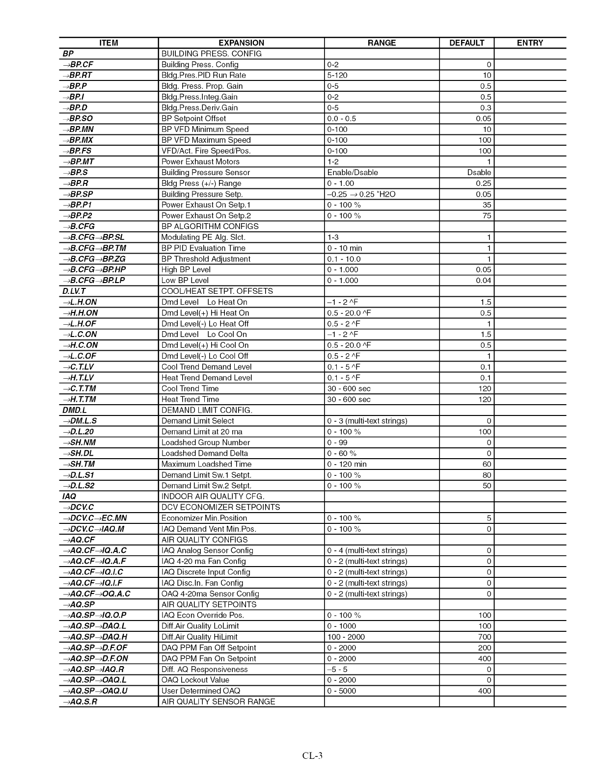
ITEM
BP
-_BP.CF
-_BP.RT
-_BP.P
-_BP.I
-_BP.D
-_BP.SO
-_BP.MN
-_BP.MX
-_BP.FS
-_BP.MT
-_BP.S
-_BP.R
-_BP.SP
-_BP.P1
-_BP.P2
-_B.CFG
-_B. CFG -_BP. SL
-_B. CFG-_BP. TM
-_B. CFG-_BP.ZG
-_B. CFG -_BP. HP
-_B. CFG-_BP.LP
D.LVT
-_L.H.ON
-_H.H.ON
-_L.H.OF
-_L.C.ON
-_H.C.ON
-_L.C.OF
-_C. T.LV
-_H. T.LV
-_C. T.TM
-_H. T.TM
DMD.L
-_DM.L.S
-_D.L.20
-_SH. NM
-_SH.DL
-_SH. TM
-_D.L.Sl
-_D.L.S2
IAQ
-_DCVC
-_DCV C-_EC.MN
-_DC V C-4A Q.M
-_AQ.CF
-_A Q.CF-4Q.A. C
-_A Q.CF-4Q.A. F
-_AQ.CF-4Q.L C
-_AQ.CF-4Q.LF
-_AQ.CF-_OQ.A.C
-_AQ.SP
-_AQ.SP-4Q.O.P
-_AQ.SP-_DAQ.L
-_AQ.SP-_DAQ.H
-_AQ.SP-_D.F.OF
-_AQ.SP-_D.F.ON
-_AQ.SP-4AQ.R
-_AQ.SP-_OAQ.L
-_AQ.SP-_OAQ.U
-_AQ.S.R
EXPANSION
BUILDING PRESS. CONFIG
Building Press. Config
Bldg.Pres.PID Run Rate
Bldg. Press, Prop, Gain
Bldg.Press.lnteg.Gain
Bldg.Press.Deriv.Gain
BP Setpoint Offset
BP VFD Minimum Speed
BP VFD Maximum Speed
VFD/Act. Fire Speed/Pos.
Power Exhaust Motors
Building Pressure Sensor
Bldg Press (+/-) Range
Building Pressure Setp.
Power Exhaust On Setp.1
Power Exhaust On Setp.2
BP ALGORITHM CONFIGS
Modulating PE AIg. Slct.
BP PID Evaluation Time
BP Threshold Adjustment
High BP Level
Low BP Level
COOL/HEAT SETPT. OFFSETS
Dmd Level Lo Heat On
Dmd Level(+) Hi Heat On
Dmd Level(-) Lo Heat Off
Dmd Level Lo Cool On
Dmd Level(+) Hi Cool On
Dmd Level(-) Lo Cool Off
Cool Trend Demand Level
Heat Trend Demand Level
Cool Trend Time
Heat Trend Time
DEMAND LIMIT CONFIG.
Demand Limit Select
Demand Limit at 20 ma
Loadshed Group Number
Loadshed Demand Delta
Maximum Loadshed Time
Demand Limit Sw.1 Setpt.
Demand Limit Sw.2 Setpt.
INDOOR AIR QUALITY CFG.
DCV ECONOMIZER SETPOINTS
Economizer Min.Position
IAQ Demand Vent Min.Pos.
AIR QUALITY CONFIGS
IAQ Analog Sensor Config
IAQ 4-20 ma Fan Config
IAQ Discrete Input Config
IAQ Disc.In. Fan Config
OAQ 4-20ma Sensor Config
AIR QUALITY SETPOINTS
IAQ Econ Override Pos.
Dill.Air Quality LoLimit
Dill.Air Quality HiLimit
DAQ PPM Fan Off Setpoint
DAQ PPM Fan On Setpoint
DiE AQ Responsiveness
OAQ Lockout Value
User Determined OAQ
AIR QUALITY SENSOR RANGE
RANGE
0-2
5-120
0-5
0-2
0-5
0.0 - 0.5
0-1O0
0-1O0
0-1O0
1-2
Enable/Dsable
0 - 1.00
-0.25 -_ 0.25 "H20
0 - 100%
0 - 100%
1-3
0 - 10 min
0.1 - 10.0
0 - 1.000
0 - 1.000
-1 - 2 AF
0.5 - 20.0 AF
0.5 - 2 AF
--1 - 2 AF
0.5 - 20.0 AF
0.5 - 2 AF
0.1 - 5AF
0.1 - 5AF
30 - 600 sec
30 - 600 sec
0 - 3 (multi-text strings)
0 - 100%
0 - 99
0 -60%
0 - 120 min
0 - 100%
0 - 100%
0 - 100%
0 - 100%
0 - 4 (multi-text strings)
0 - 2 (multi-text strings)
0 - 2 (multi-text strings)
0 - 2 (multi-text strings)
0 - 2 (multi-text strings)
0-100 %
0-1000
100-2000
0-2000
0-2000
-5-5
0-2000
0-5000
DEFAULT
o
lO
0.5
0.5
0.3
o.o5
lO
1oo
1oo
1
Dsable
0.25
0.05
35
75
1
1
1
0.05
0.04
1.5
0.5
1
1.5
0.5
1
0.1
0.1
12O
12O
o
1oo
o
o
6o
8o
5o
5
o
o
o
o
o
o
1oo
1oo
7oo
2oo
4oo
0
0
4oo
ENTRY
CL-3
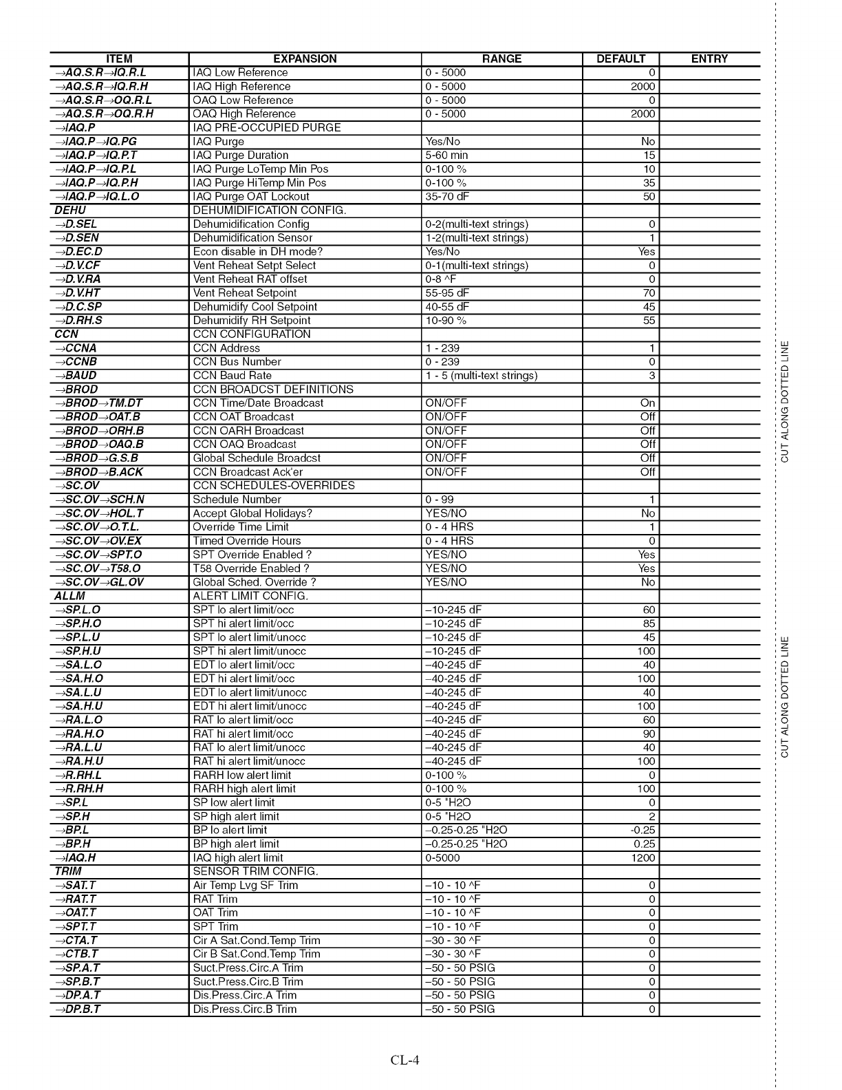
ITEM EXPANSION RANGE DEFAULT ENTRY
-*AQ.S.R-*IQ.R.L IAQ Low Reference 0 -5000 0
-,AQ.S.R-,IQ.R.H IAQ High Reference 0 - 5000 2000
-eAQ.S.R-eOQ.R.L OAQ Low Reference 0 - 5000 0
-,AQ.S.R-,OQ.R.H OAQ High Reference 0 - 5000 2000
-,IAQ.P IAQ PRE-OCCUPIED PURGE
-,IAQ.P-,IQ.PG IAQ Purge Yes/No No
-,IAQ.P-,IQ.P.T IAQ Purge Duration 5-60 min 15
-,IAQ.P-,IQ.P.L IAQ Purge LoTemp Min Pos 0-100 % 10
-,IAQ.P-,IQ.P.H IAQ Purge HiTemp Min Pos 0-100 % 35
-,IAQ.P-,IQ.L.O IAQ Purge OAT Lockout 35-70 dF 50
DEHU DEHUMIDIFICATION CONFIG.
-_D.SEL Dehumidification Config 0-2(multi-text strings) 0
-_D.SEN Dehumidification Sensor 1-2(multi-text strings) 1
-_D.EC.D Econ disable in DH mode? Yes/No Yes
-_D. VCF Vent Reheat Setpt Select 0-1 (multi-text strings) 0
-_D. VRA Vent Reheat RAT offset 0-8 AF 0
-_D. VHT Vent Reheat Setpoint 55-95 dF 70
-_D.C.SP Dehumidify Cool Setpoint 40-55 dF 45
-_D.RH.S Dehumidify RH Setpoint 10-90 % 55
CCN CCN CONFIGURATION
-,CCNA CCN Address 1 - 239 1
-,CCNB CCN Bus Number 0 - 239 0
-_BAUD CCN Baud Rate 1 - 5 (multi-text strings) 3
-_BROD CCN BROADCST DEFINITIONS
-_BROD-,TM.DT CCN Time/Date Broadcast ON/OFF On
-_BROD-,OAT.B CCN OAT Broadcast ON/OFF Off
-_BROD-,ORH.B CCN OARH Broadcast ON/OFF Off
-_BROD-,OAQ.B CCN OAQ Broadcast ON/OFF Off
-_BROD-,G.S.B Global Schedule Broadcst ON/OFF Off
-_BROD-,B.ACK CCN Broadcast Ack'er ON/OFF Off
-_SC.OV CCN SCHEDULES-OVERRIDES
-_SC.OV-eSCH.N Schedule Number 0 - 99 1
-_SC.OV-eHOL.T Accept Global Holidays? YES/NO No
-_SC.OV-eO.T.L. Override Time Limit 0 - 4 HRS 1
-_SC.OV-,OVEX Timed Override Hours 0 - 4 HRS 0
-_SC.OV-eSPT.O SPT Override Enabled ? YES/NO Yes
-_SC.OV-eT58.0 T58 Override Enabled ? YES/NO Yes
-_SC.OV-eGL.OV Global Sched. Override ? YES/NO No
ALLM ALERT LIMIT CONFIG.
-_SP.L.O SPT Io alert limit/occ -10-245 dF 60
-_SP.H.O SPT hi alert limit/occ -10-245 dF 85
-_SP.L.U SPT Io alert limit/unocc -10-245 dF 45
-_SP.H.U SPT hi alert limit/unocc -10-245 dF 100
-_SA.L.O EDT Io alert limit/occ -40-245 dF 40
-_SA.H.O EDT hi alert limit/occ -40-245 dF 100
-_SA.L.U EDT Io alert limit/unocc -40-245 dF 40
-_SA.H.U EDT hi alert limit/unocc -40-245 dF 100
-_RA.L.O RAT Io alert limit/occ -40-245 dF 60
-_RA.H.O RAT hi alert limit/occ -40-245 dF 90
-_RA.L.U RAT Io alert limit/unocc -40-245 dF 40
-_RA.H.U RAT hi alert limit/unocc -40-245 dF 100
-_R.RH.L RARH low alert limit 0-100 % 0
-_R.RH.H RARH high alert limit 0-100 % 100
-_SP.L SP low alert limit 0-5 "H20 0
-_SP.H SP high alert limit 0-5 "H20 2
-_BP.L BP Io alert limit -0.25-0.25 "H20 -0.25
-_BP.H BP high alert limit -0.25-0.25 "H20 0.25
-,IAQ.H IAQ high alert limit 0-5000 1200
TRIM SENSOR TRIM CONFIG.
-_SAT.T Air Temp Lvg SF Trim -10 - 10 AF 0
-_RAT.T RAT Trim -10 - 10 AF 0
-*OAT.T OAT Trim -10 - 10 AF 0
-_SPT.T SPT Trim -10 - 10 AF 0
-*CTA.T Cir A Sat.Cond.Temp Trim -30 - 30 AF 0
-*CTB.T Cir B Sat.Cond.Temp Trim -30 - 30 AF 0
-_SP.A.T Suct.Press.Circ.A Trim -50 - 50 PSIG 0
-_SP.B.T Suct.Press.Circ.B Trim -50 - 50 PSIG 0
-_DP.A.T Dis.Press.Circ.A Trim -50 - 50 PSIG 0
-_DP.B.T Dis.Press.Circ.B Trim -50 - 50 PSIG 0
LU
Z
-7
C3
LU
I-
I-
©
C3
(.5
Z
o
<(
I-
O
LU
Z
--7
C3
LU
i-
6
C3
(.5
Z
o
<(
I-
CL-4
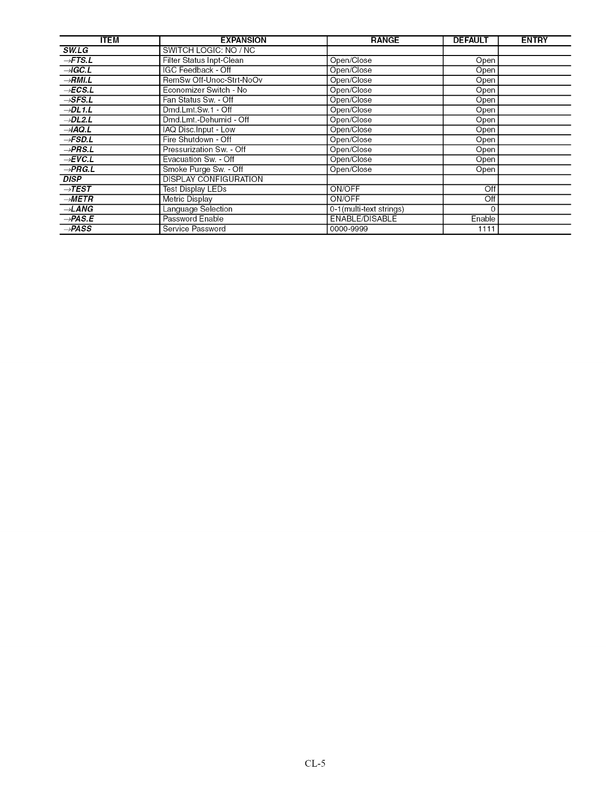
ITEM EXPANSION RANGE DEFAULT ENTRY
SW.LG SWITCH LOGIC: NO /NC
-_FTS.L Filter Status Inpt-Clean Open/Close Open
-_IGC.L IGC Feedback - Off Open/Close Open
-_RMI.L RemSw Off-Unoc-Strt-NoOv Open/Close Open
-_ECS.L Economizer Switch - No Open/Close Open
-_SFS.L Fan Status Sw, - Off Open/Close Open
-_DL I.L Dmd,Lmt,Sw, 1 - Off Open/Close Open
-_DL2.L Dmd,Lmt,-Dehumid - Off Open/Close Open
-_IAQ.L IAQ Disc,Input - Low Open/Close Open
-_FSD.L Fire Shutdown - Off Open/Close Open
-_PRS.L Pressurization Sw, - Off Open/Close Open
-_EVC.L Evacuation Sw, - Off Open/Close Open
-_PRG.L Smoke Purge Sw, - Off Open/Close Open
DISP DISPLAY CONFIGURATION
-+TEST Test Display LEDs ON/OFF Off
-_METR Metric Display ON/OFF Off
-_LANG Language Selection 0-1 (multi-text strings) 0
-_PAS.E Password Enable ENABLE/DISABLE Enable
-+PASS Service Password 0000-9999 1111
CL-5
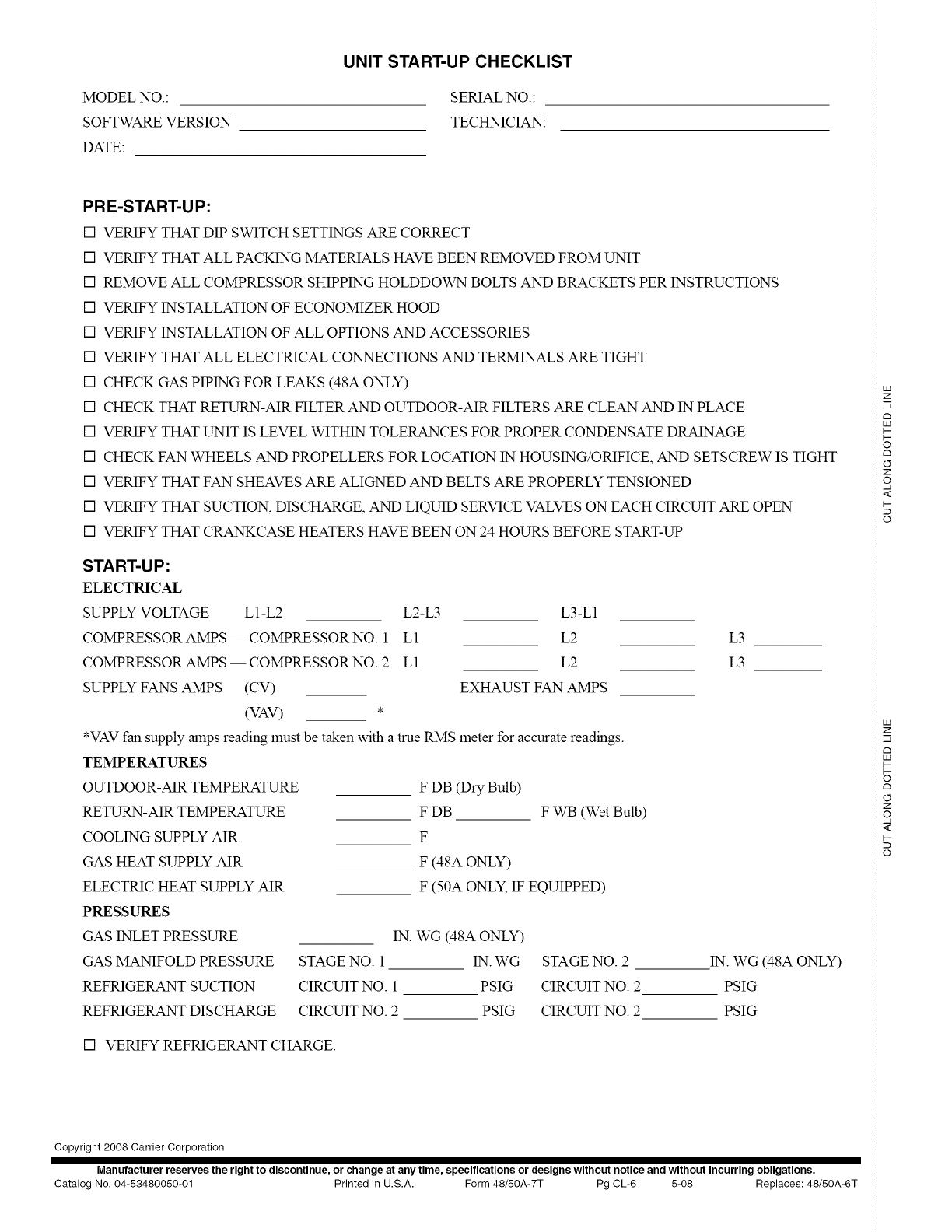
MODELNO.:
SOFTWARE VERSION
DATE:
UNIT START-UP CHECKLIST
SERIAL NO.:
TECHNICIAN:
PRE-START-UP:
[] VERIFY THAT DIP SWITCH SETTINGS ARE CORRECT
[] VERIFY THAT ALL PACK1NG MATERIALS HAVE BEEN REMOVED FROM UNIT
[] REMOVE ALL COMPRESSOR SHIPPING HOLDDOWN BOLTS AND BRACKETS PER INSTRUCTIONS
[] VERIFY INSTALLATION OF ECONOMIZER HOOD
[] VERIFY INSTALLATION OF ALL OPTIONS AND ACCESSORIES
[] VERIFY THAT ALL ELECTRICAL CONNECTIONS AND TERMINALS ARE TIGHT
[] CHECK GAS PIPING FOR LEAKS (48A ONLY)
[] CHECK THAT RETURN-MR FILTER AND OUTDOOR-MR FILTERS ARE CLEAN AND IN PLACE
[] VERIFY THAT UNIT IS LEVEL WITHIN TOLERANCES FOR PROPER CONDENSATE DRAINAGE
[] CHECK FAN WHEELS AND PROPELLERS FOR LOCATION IN HOUSING/ORIFICE, AND SETSCREW IS TIGHT
[] VERIFY THAT FAN SHEAVES ARE ALIGNED AND BELTS ARE PROPERLY TENSIONED
[] VERIFY THAT SUCTION, DISCHARGE, AND LIQUID SERVICE VALVES ON EACH CIRCUIT ARE OPEN
[] VERIFY THAT CRANKCASE HEATERS HAVE BEEN ON 24 HOURS BEFORE START-UP
START-UP:
ELECTRICAL
SUPPLY VOLTAGE L l-L2
COMPRESSOR AMPS -- COMPRESSOR NO. 1
COMPRESSOR AMPS -- COMPRESSOR NO. 2
SUPPLY FANS AMPS (CV)
(VAV) *
L2-L3 L3-L1
L1 L2 L3
L1 L2 L3
EXHAUST FAN AMPS
*VAV fan supply amps reading must be taken with a true RIMS meter for accurate readings.
F DB (Dry Bulb)
F DB F Vv_B(Wet Bulb)
F
F (481 ONLY)
F (501 ONLY, IF EQUIPPED)
IN. WG (48A ONLY)
STAGE NO. 1 IN. WG STAGE NO. 2
CIRCUIT NO. 1 PSIG CIRCUIT NO. 2
CIRCUIT NO. 2 PSIG CIRCUIT NO. 2
TEMPERATURES
OUTDOOR-MR TEMPERATURE
RETURN-MR TEMPERATURE
COOLING SUPPLY MR
GAS HEAT SUPPLY MR
ELECTRIC HEAT SUPPLY MR
PRESSURES
GAS INLET PRESSURE
GAS MANIFOLD PRESSURE
REFRIGERANT SUCTION
REFRIGERANT DISCHARGE
IN. WG (48A ONLY)
PSIG
PSIG
[] VERIFY REFRIGERANT CHARGE.
UA
Z
-q
c3
UA
b-
b-
o
C3
Z
q
<
ti
D
©
iii
Z
C3
iii
ti
6
C3
Z
q
<
ti
Copyright 2008 Carrier Corporation
Manufacturer reserves the right to discontinue, or change at any time, specifications or designs without notice and without incurring obligations.
Catalog No. 04-53480050-01 Printed in U.S.A. Form 48/50A-7T Pg CL-6 5-08 Replaces: 48/50A-6T
