CARRIER Furnace/Heater, Gas Manual L0902273
User Manual: CARRIER CARRIER Furnace/Heater, Gas Manual CARRIER Furnace/Heater, Gas Owner's Manual, CARRIER Furnace/Heater, Gas installation guides
Open the PDF directly: View PDF ![]() .
.
Page Count: 2
Installation Instructions
NOTE: Read the entire instruction manual before starting the
installation.
SAFETY CONSIDERATIONS
Installing and servicing of heating equipment can be hazardous
due to gas and electrical components. Only trained personnel
should install or service heating equipment.
Untrained personnel can perform basic maintenance functions
such as cleaning coils or cleaning and replacing filters. All other
operations should be performed by trained service personnel.
When working on heating equipment, observe precautions in the
literature, on tags, and on labels attached to the unit.
Follow all safety codes. Wear safety glasses and work gloves.
Have fire extinguisher available.
Recognize safety information. This is the safety-alert symbol "_.
When you see this symbol on the furnace and in instructions or
manuals, be alert to the potential for personal iniury.
Understand the signal word DANGER, WARNING, and
CAUTION. These words are used with the safety-alert symbol.
DANGER identifies the most serious hazards which will result in
severe personal iniury or death. WARNING signifies a hazard
which could result in personal iniury or death. CAUTION is
used to identify unsafe practices which may result in minor
personal iniury or product and property damage. NOTE is used
to highlight suggestions that will result in enhanced installation,
reliability, or operation.
ELECTRICALSHOCK HAZARD
Failure to follow this warning could result in personal
iniury or death.
Before beginning any installation or modification, be sure
the main electrical disconnect switch is in the OFF position.
Unit may have more than one power switch.
UNIT OPERATION HAZARD
Failure to
damage.
Label all
controls.
follow this caution may result in equipment
wires prior to disconnection when servicing
INTRODUCTION
This instruction covers installation of the electronically
commuted motor (ECM) Inducer Motor Kit Part No.
324906-762 on all models of 355MAV, 355AAV, 355BAV
355CAV, 58MVP, 58MVB, 58MVC and 58UVB Condensing
Gas Furnaces (40,000 through 120,000 Btuh inputs).
DESCRIPTION AND USAGE
Use this ICM inducer motor kit to replace a failed inducer motor
assembly.
This kit contains the following items:
Inducer Assembly 1
Installation Instructions 1
Inducer Spacer Kit 1
NOTE: Inducer assembly consists of motor, wheel, motor
mount, motor weight, inducer cover, inducer housing, vent cap,
and vent clamp.
INSTALLATION
Step 1-- Remove Old Motor Assembly
1. Turn electrical supply to unit to OFF position.
2. Remove main furnace door.
3. Remove lower drain tube from inducer housing cover.
4. Remove pressure switch assembly by removing 2 screws,
(See Fig. 1.)
5. Remove pressure switch tube at tee leading to burner box
and gas valve.
6. Move pressure switch assembly to side,
7. Remove combustion vent pipe by loosening clamp on
rubber connector and remove from housing.
8. Remove Inducer Water Shield (if present) by removing 2
screws, (See Fig. 1.)
9. Disconnect wire harness connector from inducer motor.
10. Remove 4 bolts securing inducer housing to cell inlet
panel.
Step 2 -- Install New Motor Assembly
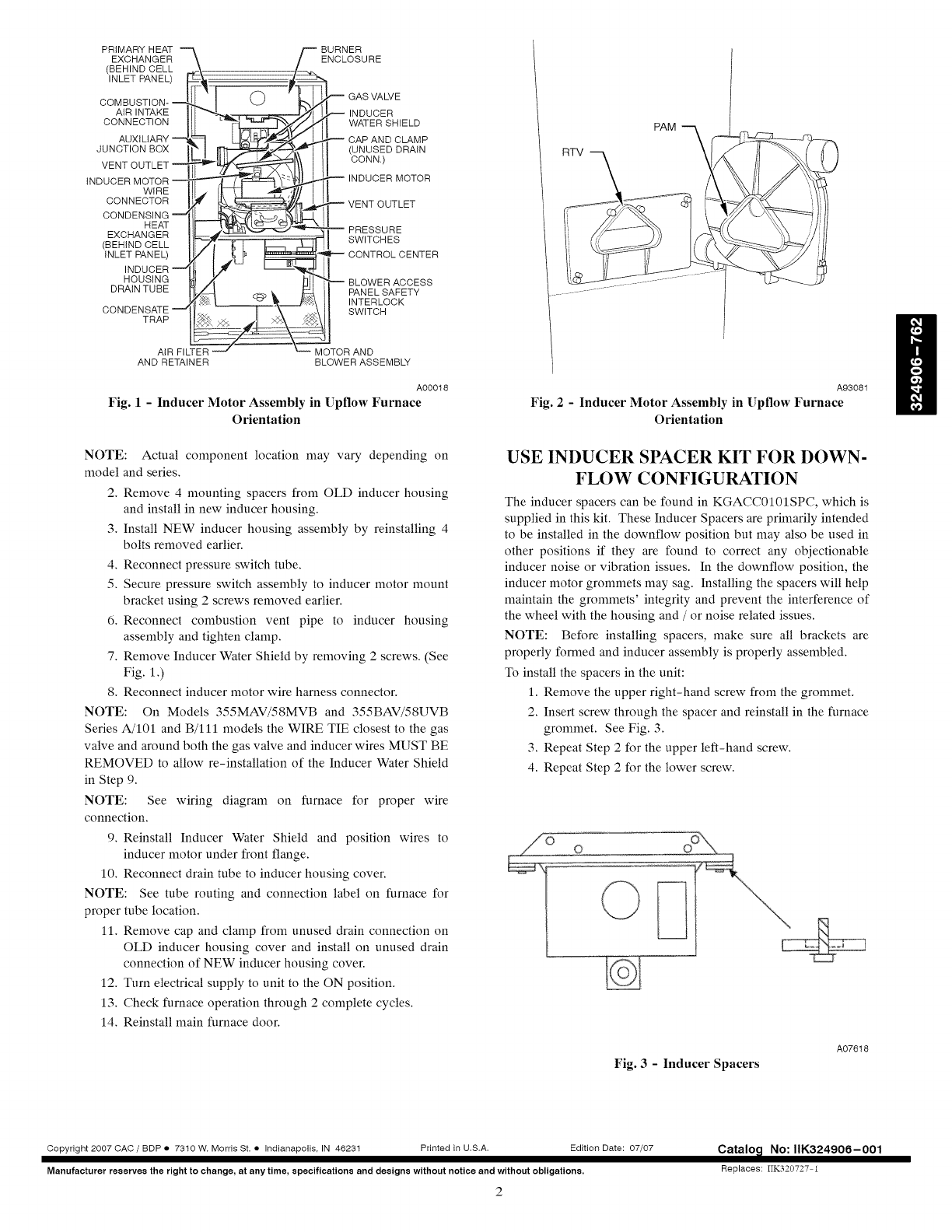
1. Inspect seal on collector box where new inducer housing
will mate to ensure no damage has occurred. (See Fig. 2.)
NOTE: If collector box seal is damaged in any way, it must be
repaired. To repair, apply sealant releasing agent such as PAM
cooking spray or equivalent (must not contain corn nor canola
oil, halogenated hydrocarbons nor aromatic content to prevent
inadequate sealing) to inducer housing. Apply a small bead of GE
RTV 162, G.E. 6702, or Dow-Corning RTV 738 sealant to
groove in collector box. G.E. 162 (P771-9003) is available
through RCD in 3-oz. tubes.
PRIMARY HEAT "_ _ BURNER
EXCHANGER \ ENCLOSURE
(BEHIND CELL ,._-\ _
INLET PANEL) _ _. ==_
OOMBUST,ON-q 'IO ' GASVALVE
AIRINTAKE [1["__ _ _'j_l_ NDUCER
CONNECT,ON WATERBR,ELO
__ _ VENT OUTLET
CONDENSINGILL__ _1-kll
EXORAN E IlL. PRESSURE
/BERINOCELL BW,TCRES
iNLET PANEL) lly [ ._ _ _ _1"_ CONTROL CENTER
DRAINTUBE PANELBAPETY
IZ!_ __\ INTERLOCK
CONDENSATE __z[ L.. ---_-'_-'\-- ._\ [_ SWITCH
TRAP >._ Zb_ _
AIR FILTE_ __-" MOTOR AND
AND RETAINER BLOWER ASSEMBLY
A00018
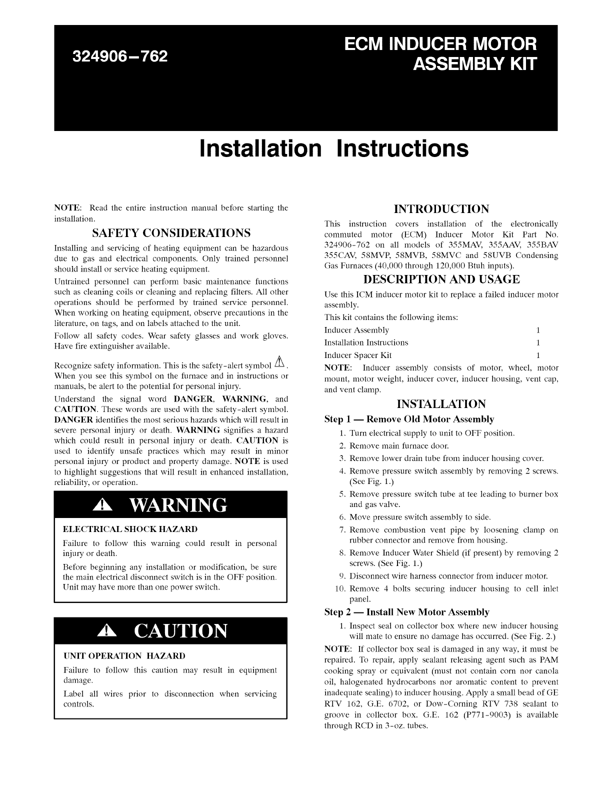
Fig. 1 - Inducer Motor Assembly in Upflow Furnace
Orientation
NOTE: Actual component location may vary depending on
model and series.
2. Remove 4 mounting spacers from OLD inducer housing
and install in new inducer housing.
3. Install NEW inducer housing assembly by reinstalling 4
bolts removed earlier.
4. Reconnect pressure switch tube.
5. Secure pressure switch assembly to inducer motor mount
bracket using 2 screws removed earlier.
6. Reconnect combustion vent pipe to inducer housing
assembly and tighten clamp.
7. Remove Inducer Water Shield by removing 2 screws. (See
Fig. 1 .)
8. Reconnect inducer motor wire harness connector.
NOTE: On Models 355MAV/58MVB and 355BAV/58UVB
Series A/101 and B/Ill models the WIRE TIE closest to the gas
valve and around both the gas valve and inducer wires MUST BE
REMOVED to allow re-installation of the Inducer Water Shield
in Step 9.
NOTE: See wiring diagram on furnace for proper wire
connection.
9. Reinstall Inducer Water Shield and position wires to
inducer motor under front flange.
10. Reconnect drain tube to inducer housing cover.
NOTE: See tube routing and connection label on furnace for
proper tube location.
11. Remove cap and clamp from unused drain connection on
OLD inducer housing cover and install on unused drain
connection of NEW inducer housing cover.
12. Turn electrical supply to unit to the ON position.
13. Check furnace operation through 2 complete cycles.
14. Reinstall main furnace door.
A93081
Fig. 2- Inducer Motor Assembly in Upflow Furnace
Orientation
USE INDUCER SPACER KIT FOR DOWN-
FLOW CONFIGURATION
The inducer spacers can be found in KGACC0101SPC, which is
supplied in this kit. These Inducer Spacers are primarily intended
to be installed in the downflow position but may also be used in
other positions if they are found to correct any objectionable
inducer noise or vibration issues. In the downflow position, the
inducer motor grommets may sag. Installing the spacers will help
maintain the grommets' integrity and prevent the interference of
the wheel with the housing and /or noise related issues.
NOTE: Before installing spacers, make sure all brackets are
properly formed and inducer assembly is properly assembled.
To install the spacers in the unit:
1. Remove the upper right-hand screw from the grommet.
2. Insert screw through the spacer and reinstall in the furnace
grommet. See Fig. 3.
3. Repeat Step 2 for the upper left-hand screw.
4. Repeat Step 2 for the lower screw.
Fig. 3 - Inducer Spacers
A07618
Copyright 2007 CAC /BDP • 7310 W. Morris St. • Indianapolis, IN 46231 Printed in U.S.A. Edition Date: 07/07
Manufacturer reserves the right to change, at any time, specifications and designs without notice and without obligations,
2
Catalo_l No: IIK324906-001
Replaces: IIK320727 i
