CARRIER Controls And HVAC Accessories Manual L0912127
User Manual: CARRIER CARRIER Controls and HVAC Accessories Manual CARRIER Controls and HVAC Accessories Owner's Manual, CARRIER Controls and HVAC Accessories installation guides
Open the PDF directly: View PDF ![]() .
.
Page Count: 31
the Expert_
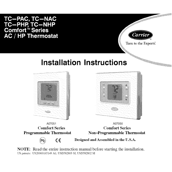
Installation
A07051
Comfort Series
Programmable Thermostat
(€
Instructions
A07050
Comfort Series
Non-Programmable Thermostat
Designed and Assembled in the U.S.A.
NOTE: Read the entire instruction manual before starting the installation.
US patents: US20060165149 AI. USD582803 SI, USD582802 SI
TABLE OF CONTENTS
PAGE
SAFETY CONSIDERATIONS .................................... 1
INSTALLATION CONSIDERATIONS .............................. 2
INSTALLATION ............................................... 3
Step 1 -- Thermostat Location ................................... 3
Step 2 -- Install Thermostat ...................................... 4
Step 3 -- Set Thermostat Configuration ............................ 8
Step 4 -- Check Thermostat Operation ............................ 16
FEATURES AND ACCESSORIES ................................ 17
OPERATIONAL AND CONNECTION INFORMATION .............. 19
WIRING DIAGRAMS .......................................... 22
THERMOSTAT CONFIGURATION RECORD ...................... 29
SAFETY CONSIDERATIONS
Read and follow manufacturer instructions careflflly. Follow all local electrical
codes during installation. All wiring must conform to local and national electrical
codes. Improper wiring or installation may damage thermostat.
Recognize safety information. This is the safety-alert symbol /_ . When you see
this symbol on the equipment and in the instruction manual, be alert to the
potential for personal injury.
Understand the signal words DANGER, WARNING, and CAUTION. These
words are used with the safety-alert symbol. DANGER identifies the most
serious hazards which will result in severe personal injury or death. WARNING
signifies a hazard which could result in personal injury or death. CAUTION is
usedto identify unsafe practices which may result in minor personal injury or
product and property damage. NOTE is used to highlight suggestions which will
result in enhanced installation, reliability, or operation.
INTRODUCTION
Carrier's Comfort 'M Series programmable thermostats are wall-mounted,
low-voltage thermostats which maintain room temperature by controlling the
operation of a heating and/or air conditioning system. Both heat pump and air
conditioner models are available, each in programmable and non-programmable
versions. A variety of features are provided including battery operation, separate
heating and cooling setpoints, auto changeover, keypad lockout, backlighting,
and built-in installer test. Programming features include 7-day (all days the
same) and 5/2 (Mon-Fri and Sat-Sun) with 2 or 4 periods per day.
This Installation Instruction covers installation, configuration, and startup of all
four versions of the Comfort Series line of thermostats. For operational details,
consult the Owner's Manual for the specific thermostat you are installing.
INSTALLATION CONSIDERATIONS
Models
There are four models in the Comfort Series: programmable and
non-programmable, AC and HR Models TC-PAC and TC-NAC are designed for
AC systems, controlling one stage of cooling and one stage of heating. They will not
operate a heat pump. Models TC-PHP and TC-NHP are designed for HP systems,
controlling one stage of cooling and two stages of heating. They can be converted to
AC operation. Select the appropriate model for the intended application.
Power
All Comfort Series models are dual powered. They can operate from batteries or
24VAC power. Operation from 24VAC is preferred if available. Battery
operation is used when there are not enough wires to support 24VAC operation
or when "armchair programming" is desired. For an AC system, up to six wires
are needed for 24VAC operation and one less wire for battery operation. For a
HP system, up to seven wires are needed for 24VAC operation and one less wire
would be sufficient for battery operation. For heat only operation with batteries,
only two wires are required. When battery operation is used, the C terminal does
not need to be connected.
Provision is also made for separate heating and cooling transformers via separable Rc
and Rh terminals which are connected via factory-installed jumper wire.
INSTALLATION
Step 1-- Thermostat Location
•Approximately 5 fl (l.5m) from floor.
• Close to or in a frequently used room, preferably on an inside
partitioning wall.
• On a section of wall without pipes or duct work.
Thermostat should NOT be mounted
• Close to a window, on an outside wall, or next to a door leading to the
outside.
• Exposed to direct light or heat from the sun, a lamp, fireplace, or other
temperature-radiating objects which could cause a false reading.
• Close to or in direct airflow from supply registers and return-air
registers.
• In areas with poor air circulation, such as behind a door or in an
alcove.
Step 2-- Install Thermostat
ELECTRICAL OPERATION HAZARD
Failure to follow this warning could result in personal injury
or death.
Before installing thermostat, turn off all power to equipment.
There may be more than one power disconnect.
1. Turn OFF all power to unit.
2. If an existing thermostat is being replaced:
a. Remove existing thermostat from wall.
b. Disconnect wires from existing thermostat, one at a time. Be careful
not to allow wires to fall back into the wall.
c. As each wire is disconnected, record wire color and terminal marking.
d. Discard or recycle old thermostat.
ENVIRONMENTAL HAZARD
Failure to follow this caution may result in environmental
damage.
Mercury is a hazardous waste. Federal regulations require that
Mercury be disposed of properly.
3. Open thermostat (mounting base) to expose mounting holes. The base
can be removed to simplify mounting. Press the thumb release at the top
ofthethermostatandsnapapartcarefullytoseparatemountingbasefrom
remainderofthermostat.
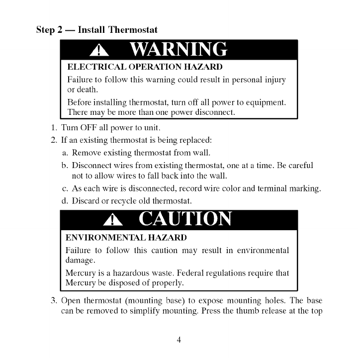
4.Routethermostatwiresthroughlargeholeinmountingbase.Levelmounting
baseagainstwall(foraestheticvalueonly--thermostatneednotbelevelfor
properoperation)andmarkwallthroughfourmountingholes.Toavoidun-
intendedbendingofwallplateplastic,allfourscrewsandanchorsmustbe
used.SeeFig.1.
A07153
Fig. 1-Backplate Mounting
5. Drill four 3/16-in. mounting holes in wall where marked.
6. Secure mounting base to wall with four screws and anchors provided. To
avoid unintended bending of wall plate plastic, all four screws and anchors
must be used. Make sure all wires extend through hole in mounting base.
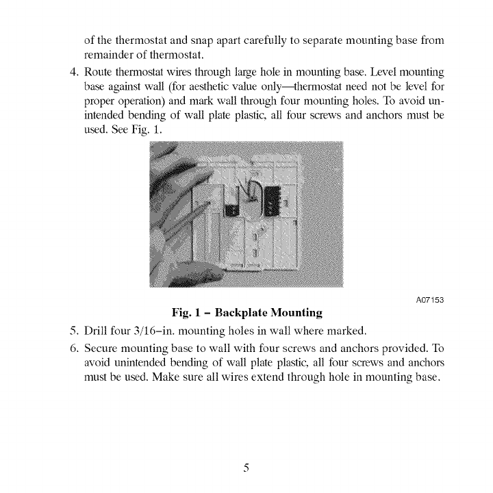
7.Adjustlengthandroutingof eachwiretoreachproperterminaland
connectorblockonmountingbasewith1/4-in.(6mm)ofextrawire.
Striponly1/4in.ofinsulationfromeachwiretopreventadjacentwires
fromshortingtogetherwhenconnected.SeeFig.2.
A07155
Fig. 2-Secure Wires to Terminal Strip
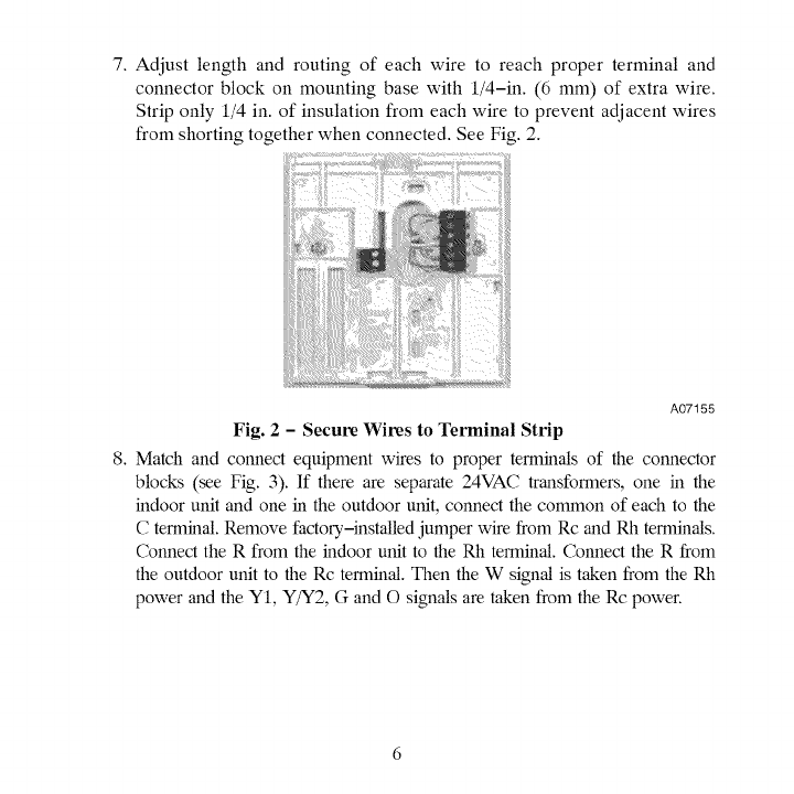
8. Match and connect equipment wires to proper terminals of the connector
blocks (see Fig. 3). If there are separate 24VAC transformers, one in the
indoor unit and one in the outdoor unit, connect the common of each to the
C terminal. Remove factory,-installed jumper wire from Rc and Rh terminals.
Connect the R from the indoor unit to the Rh terminal. Connect the R from
the outdoor unit to the Rc terminal. Then the W signal is taken from the Rh
power and the YI, Y/Y2, G and O signals are taken from the Rc power.
O/B - reversing valve J (.__)J
Y1 - Cooling L_J
Low Stage
m
(_ Rc - 24 VAC, from cooling equipment
(_) Rh - 24 VAC, from heating equipment
(_ W- Heating
(_ C - Common 24 VAC
(_ G - Fan
(_ YIY2 - Cooling High or Single Stage
A09271
Fig. 3 - Terminal Designations
ELECTRICAL OPERATION HAZARD
Failure to follow this caution may result in equipment damage
or improper operation.
Improper wiring or installation may damage the thermostat.
Check to make sure wiring is correct before proceeding with
installation or turning on unit.
9. Push any excess wire into wall and against mounting base. Seal hole in
wall to prevent air leaks. Leaks can affect operation.
10. Snap case back together. Attach thermostat to backplate by inserting tab
on bottom edge and hinging up until top snap secures. See Fig. 4.
A07157
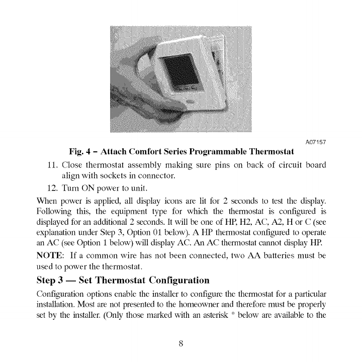
Fig. 4 -Attach Comfort Series Programmable Thermostat
11. Close thermostat assembly making sure pins on back of circuit board
align with sockets in connector.
12. Turn ON power to unit.
When power is applied, all display icons are lit for 2 seconds to test the display.
Following this, the equipment type for which the thermostat is configured is
displayed for an additional 2 seconds. It will be one of HR H2, AC, A2, H or C (see
explanation under Step 3, Option 01 below). A HP thermostat configured to operate
an AC (see Option I below) will display AC. An AC thermostat cannot display HR
NOTE: If a common wire has not been connected, two AA batteries must be
used to power the thermostat.
Step 3-- Set Thermostat Configuration
Configuration options enable the installer to configure the thermostat for a particular
installation. Most are not presented to the homeowner and therefore must be properly
set by the installer. (Only those marked with an asterisk * below are available to the
homeowner.)Followingisalistoftheoptionsavailable,anexplanationoftheir
flmction,andtheirfactory,defaultsettings.NotallnumbersareusedintheComfort
Seriesbecausenotalloptionsareavailableinthisseries- andnumberingis
consistentacrosstheTB,TC,andTPthermostatlines.
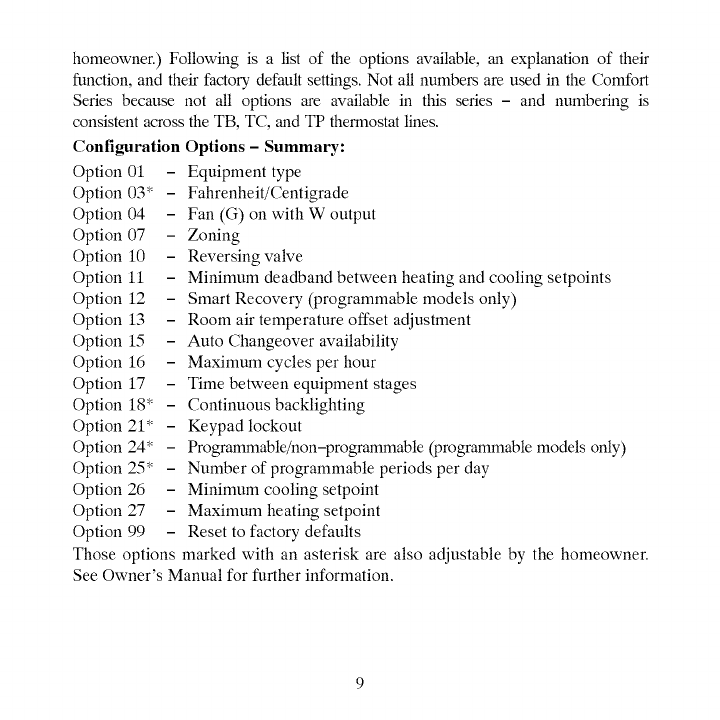
ConfigurationOptions- Summary:
Option01 - Equipmenttype
Option03* - Fahrenheit/Centigrade
Option04 - Fan(G)onwithWoutput
Option07 - Zoning
Option10 - Reversingvalve
Option11 - Minimumdeadbandbetweenheatingandcoolingsetpoints
Option12 - SmartRecovery(programmablemodelsonly)
Option13 - Roomairtemperatureoffsetadjustment
Option15 - AutoChangeoveravailability
Option16 - Maximumcyclesperhour
Option17 - Timebetweenequipmentstages
Option18"- Continuousbacklighting
Option21" - Keypadlockout
Option24* - Programmable/non-programmable(programmablemodelsonly)
Option25* - Numberofprogrammableperiodsperday
Option26 - Minimumcoolingsetpoint
Option27 - Maximumheatingsetpoint
Option99 - Resettofactorydefaults
Thoseoptionsmarkedwithanasteriskarealsoadjustablebythehomeowner.
SeeOwner'sManualforfurtherinformation.
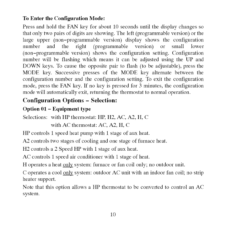
ToEnterthe Configuration Mode:
Press and hold the FAN key for about 10 seconds until the display changes so
that only two pairs of digits are showing. The left (programmable version) or the
large upper (non-programmable version) display shows the configuration
number and the right (programmable version) or small lower
(non-programmable version) shows the configuration setting. Configuration
number will be flashing which means it can be adjusted using the UP and
DOWN keys. To cause the opposite pair to flash (to be adjustable), press the
MODE key. Successive presses of the MODE key alternate between the
configuration number and the configuration setting. To exit the configuration
mode, press the FAN key. If no key is pressed for 3 minutes, the configuration
mode will automatically exit, returning the thermostat to normal operation.
Configuration Options - Selection:
Option 01 - Equipment type
Selections: with HP thermostat: HP, H2, AC, A2, H, C
with AC thermostat: AC, A2, H, C
HP controls 1 speed heat pump with 1 stage of aux heat.
A2 controls two stages of cooling and one stage of furnace heat.
H2 controls a 2 Speed HP with 1 stage of aux heat.
AC controls 1 speed air conditioner with 1 stage of heat.
H operates a heat _ system: furnace or fan coil only; no outdoor unit.
C operates a cool _ system: outdoor AC unit with an indoor fan coil; no strip
heater support.
Note that this option allows a HP thermostat to be converted to control an AC
system.
10
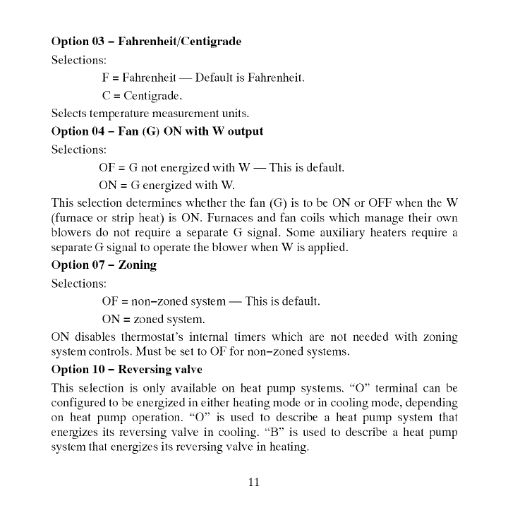
Option 03 - Fahrenheit/Centigrade
Selections:
F = Fahrenheit -- Default is Fahrenheit.
C=Centigrade.
Selects temperature measurement units.
Option 04 - Fan (G) ON with W output
Selections:
OF = G not energized with W -- This is default.
ON = G energized with W.
This selection determines whether the fan (G) is to be ON or OFF when the W
(furnace or strip heat) is ON. Furnaces and fan coils which manage their own
blowers do not require a separate G signal. Some auxiliary heaters require a
separate G signal to operate the blower when W is applied.
Option 07 - Zoning
Selections:
OF = non-zoned system -- This is default.
ON = zoned system.
ON disables thermostat's internal timers which are not needed with zoning
system controls. Must be set to OF for non-zoned systems.
Option 10 -Reversing valve
This selection is only available on heat pump systems. "O" terminal can be
configured to be energized in either heating mode or in cooling mode, depending
on heat pump operation. :'O" is used to describe a heat pump system that
energizes its reversing valve in cooling. :'B" is used to describe a heat pump
system that energizes its reversing valve in heating.
11
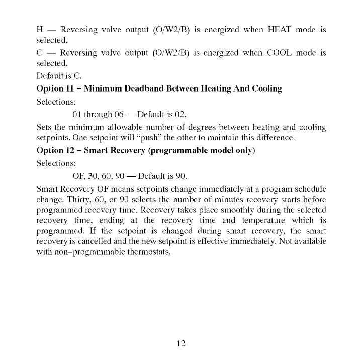
H-- Reversingvalveoutput(O/W2/B)is energizedwhenHEATmodeis
selected.
C-- Reversingvalveoutput(O/W2/B)isenergizedwhenCOOLmodeis
selected.
DefaultisC.
Option11 -Minimum Deadband Between Heating And Cooling
Selections:
01 through 06 -- Default is 02.
Sets the minimum allowable number of degrees between heating and cooling
setpoints. One setpoint will "push" the other to maintain this difference.
Option 12 - Smart Recovery (programmable model only)
Selections:
OF, 30, 60, 90 -- Default is 90.
Smart Recovery OF means setpoints change immediately at a program schedule
change. Thirty, 60, or 90 selects the number of minutes recovery starts before
programmed recovery time. Recovery takes place smoothly during the selected
recovery time, ending at the recovery time and temperature which is
programmed. If the setpoint is changed during smart recovery, the smart
recovery is cancelled and the new setpoint is effective immediately. Not available
with non-programmable thermostats.
12
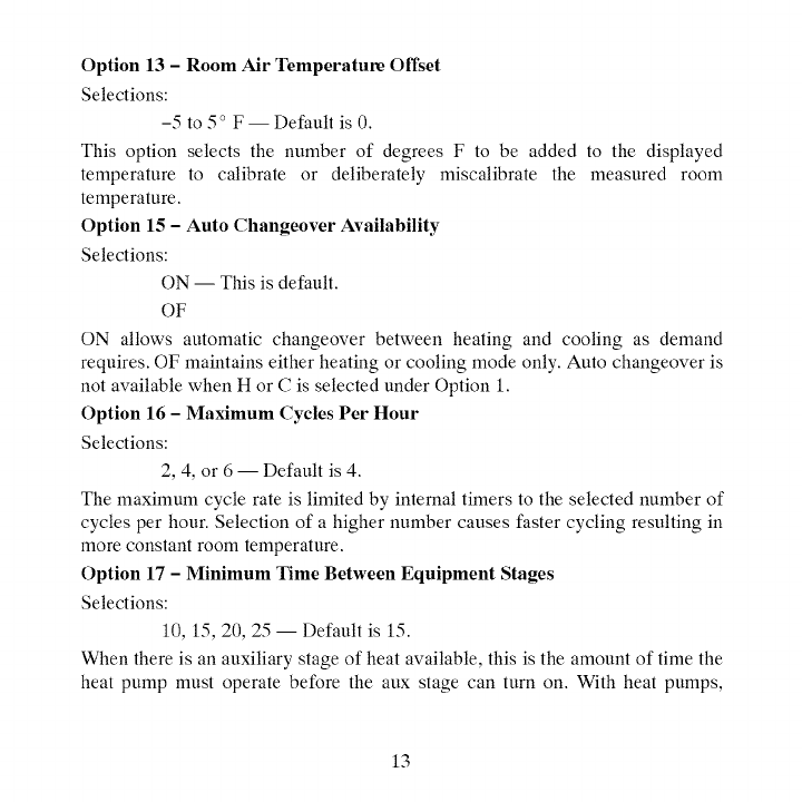
Option13 - Room Air Temperature Offset
Selections:
-5 to 5 _' F-- Default is 0.
This option selects the number of degrees F to be added to the displayed
temperature to calibrate or deliberately miscalibrate the measured room
temperature.
Option 15 - Auto Changeover Availability
Selections:
ON -- This is default.
OF
ON allows automatic changeover between heating and cooling as demand
requires. OF maintains either heating or cooling mode only. Auto changeover is
not available when H or C is selected under Option 1.
Option 16 -Maximum Cycles Per Hour
Selections:
2, 4, or 6 -- Default is 4.
The maximum cycle rate is limited by internal timers to the selected number of
cycles per hour. Selection of a higher number causes faster cycling resulting in
more constant room temperature.
Option 17 -Minimum Time Between Equipment Stages
Selections:
10, 15, 20, 25 -- Default is 15.
When there is an auxiliary stage of heat available, this is the amount of time the
heat pump must operate before the aux stage can turn on. With heat pumps,
13
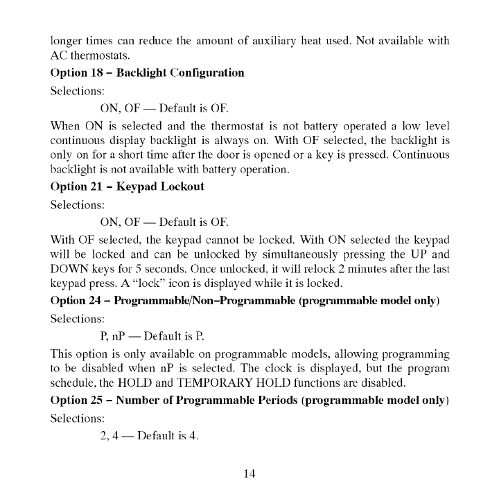
longertimescanreducetheamountofauxiliaryheatused.Notavailablewith
ACthermostats.
Option18 -Baeldight Configuration
Selections:
ON, OF -- Default is OF.
When ON is selected and the thermostat is not battery operated a low level
continuous display backlight is always on. With OF selected, the backlight is
only on for a short time after the door is opened or a key is pressed. Continuous
backlight is not available with battery operation.
Option 21 - Keypad Lockout
Selections:
ON, OF -- Default is OF.
With OF selected, the keypad cannot be locked. With ON selected the keypad
will be locked and can be unlocked by simultaneously pressing the UP and
DOWN keys for 5 seconds. Once unlocked, it will relock 2 minutes after the last
keypad press. A "lock" icon is displayed while it is locked.
Option 24 - Ptx)grammable/Non-Ptx)grammable (ptx)grammable model only)
Selections:
P, nP -- Default is R
This option is only available on programmable models, allowing programming
to be disabled when nP is selected. The clock is displayed, but the program
schedule, the HOLD and TEMPORARY HOLD functions are disabled.
Option 25 -Number of Programmable Periods (programmable model only)
Selections:
2, 4 -- Default is 4.
14
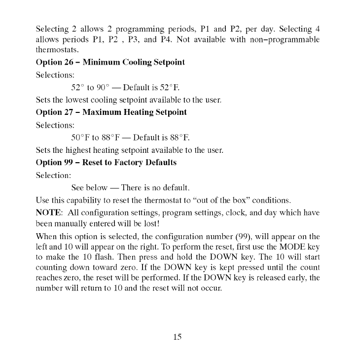
Selecting2 allows2 programmingperiods,P1andP2,perday.Selecting4
allowsperiodsP1,P2, P3,andP4.Notavailablewithnon-programmable
thermostats.
Option26-Minimum Cooling Setpoint
Selections:
52 _' to 90 _' -- Default is 52_'F.
Sets the lowest cooling setpoint available to the user.
Option 27 -Maximum Heating Setpoint
Selections:
50_'F to 88_'F -- Default is 88_'F.
Sets the highest heating setpoint available to the user.
Option 99 -Reset to Factory Defaults
Selection:
See below -- There is no default.
Use this capability to reset the thermostat to "out of the box" conditions.
NOTE: All configuration settings, program settings, clock, and day which have
been manually entered will be lost!
When this option is selected, the configuration number (99), will appear on the
left and 10 will appear on the right. To perform the reset, first use the MODE key
to make the 10 flash. Then press and hold the DOWN key. The 10 will start
counting down toward zero. If the DOWN key is kept pressed until the count
reaches zero, the reset will be performed. If the DOWN key is released early, the
number will return to 10 and the reset will not occur.
15
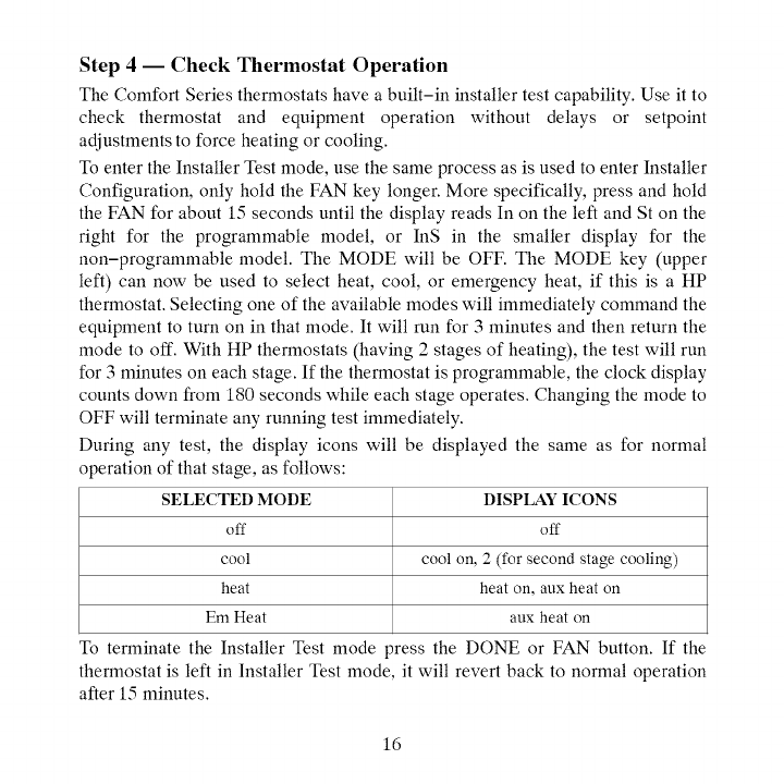
Step 4 -- Check Thermostat Operation
The Comfort Series thermostats have abuilt-in installer test capability. Use it to
check thermostat and equipment operation without delays or setpoint
adjustments to force heating or cooling.
To enter the Installer Test mode, use the same process as is used to enter Installer
Configuration, only hold the FAN key longer. More specifically, press and hold
the FAN for about 15 seconds until the display reads In on the left and St on the
right for the programmable model, or InS in the smaller display for the
non-programmable model. The MODE will be OFF. The MODE key (upper
left) can now be used to select heat, cool, or emergency heat, if this is a HP
thermostat. Selecting one of the available modes will immediately command the
equipment to turn on in that mode. It will run for 3 minutes and then return the
mode to off. With HP thermostats (having 2 stages of heating), the test will run
for 3 minutes on each stage. If the thermostat is programmable, the clock display
counts down from 180 seconds while each stage operates. Changing the mode to
OFF will terminate any running test immediately.
During any test, the display icons will be displayed the same as for normal
operation of that stage, as follows:
SELECTED MODE
off
cool
heat
Em Heat
To terminate the Installer Test mode
DISPLAY ICONS
off
cool on, 2 (for second stage cooling)
heat on, aux heat on
aux heat on
_ress the DONE or FAN button. If the
thermostat is left in Installer Test mode, it will revert back to normal operation
after 15 minutes.
16
Checklist
1.Runequipmentthroughseveralheatingandcoolingcyclestoensure
properoperation.Tooperatethethermostatinitsnormaloperatingmode,
consulttheOwner'sManual.
2.Iftheequipmentistobeleftinoperation,thesetpoints,operatingmode,
andpossiblyprogramschedulemustbeproperlyselected.
3.Putawaytoolsandinstrumentsandcleanupdebris.
4.ReviewandleaveOwner'sGuide with owner.
FEATURES AND ACCESSORIES
Home, Away, Sleep (programmable models only)
This feature provides three button selections which select from three
predetermined pairs of heat and cool setpoints. In programmed versions, one of
these three choices can be selected for any programmed period. To change these
settings, a temperature is first selected and then the key pressed and held, similar
to setting stations on a push-button radio. See Owner's Manual for details.
Clock (programmable models only)
Without batteries the clock will continue to operate for 8 hours while power is
removed. With batteries, the clock operates until the end of the battery life.
Batteries
Battery operation is available for installations where there is no common (C)
wire available at the thermostat or where operation is to continue while the
thermostat is removed from the wall, usually to facilitate remote (armchair)
programming. For battery operation, install two alkaline AA batteries. The
thermostat is designed to operate up to one year on a set of batteries. A battery
indicator on the display warns when battery replacement is needed. See
17
HomeownersGuidefordetails.If batteriesareinstalledandthethermostatis
operatedfrom24VACpower,batteryoperationwilloccuronlywhen24VAC
powerisnotpresent.Thechangeoverbetween24VACpowerandbatterypower
isautomatic.
Display Lighting
The display has two levels of lighting, high level and low level. High level
lighting comes on for 10 seconds when the door is opened and/or buttons are
being pressed with 24VAC and with batteries. Low level lighting is only
available if the thermostat is operated from 24VAC. It is not available with
batteries. The low level can be selected (see Option 18) for continuous backlight.
Door Switch
When the door is opened, the display changes from its normal operation view.
The large temperature display disappears so it will be available for other user
functions. If the door is left open for 3 minutes, the display reverts to normal
operation.
Mounting Options
For those installations requiring it, mounting hole locations for the
programmable model are spaced to fit either a horizontal or vertical junction box.
Mounting hole locations for the non-programmable are spaced to fit a horizontal
junction box.
18
OPERATIONAL AND CONNECTION INFORMATION
Rc/Rh Connections
For installations having aseparate 24VAC transformer for heating and cooling,
the R connection can be separated into two connections, one for each
transformer. This allows isolation between the two transformers to be preserved.
To separate Rc from Rh, remove the factory supplied jumper between the Rc and
Rh terminals. The Rh terminal powers the W output. The Rc terminal powers the
Y1, Y/Y2, Gand O outputs.
Wiring
Wire length should be no more than 250 ft. (76m). Use 22 AWG for normal
wiring applications. Continuous wire lengths over 100 ft. (30.5m) should use 20
AWG or larger.
O/B Terminal - On HP Thermostat Only
This terminal is normally connected to the reversing valve of the heat pump. It is
called O when the valve is energized in cooling and B when it is energized in
heating. Option 10 of the Configuration Options makes the O/B selection.
Timers
There are several timers which influence the thermostat's operation:
If any of the timers listed below is preventing the equipment from turning on, the
display icons which show the equipment is operating will be flashing to indicate
a turn-on delay is present.
Five-Minute Compressor Timeguard
This timer prevents the compressor from starting unless it has been off for 5
minutes. It can be defeated for one cycle by simultaneously pressing the FAN
and UP keys.
19
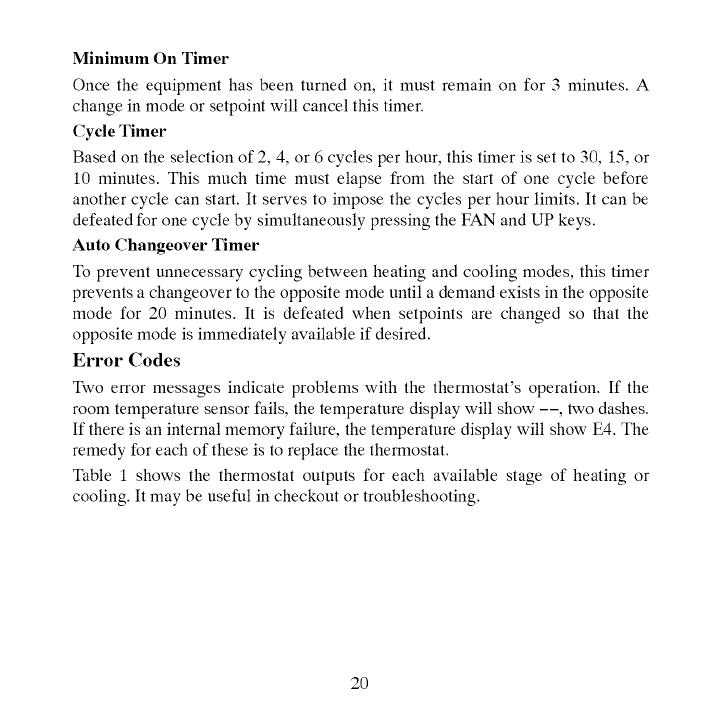
MinimumOnTimer
Oncetheequipmenthasbeenturnedon,it mustremainonfor3minutes.A
changeinmodeorsetpointwillcancelthistimer.
CycleTimer
Basedontheselectionof2,4,or6cyclesperhour,thistimerissetto30,15,or
10minutes.Thismuchtimemustelapsefromthestartofonecyclebefore
anothercyclecanstart.It servestoimposethecyclesperhourlimits.Itcanbe
defeatedforonecyclebysimultaneouslypressingtheFANandUPkeys.
AutoChangeoverTimer
Topreventunnecessarycyclingbetweenheatingandcoolingmodes,thistimer
preventsachangeovertotheoppositemodeuntilademandexistsintheopposite
modefor20minutes.It isdefeatedwhensetpointsarechangedsothatthe
oppositemodeisimmediatelyavailableif desired.
ErrorCodes
Twoerrormessagesindicateproblemswiththethermostat'soperation.If the
roomtemperaturesensorfails,thetemperaturedisplaywillshow--, twodashes.
Ifthereisaninternalmemoryfailure,thetemperaturedisplaywillshowE4.The
remedyforeachoftheseistoreplacethethermostat.
Table1showsthethermostatoutputsforeachavailablestageofheatingor
cooling.Itmaybeusefulincheckoutortroubleshooting.
2O
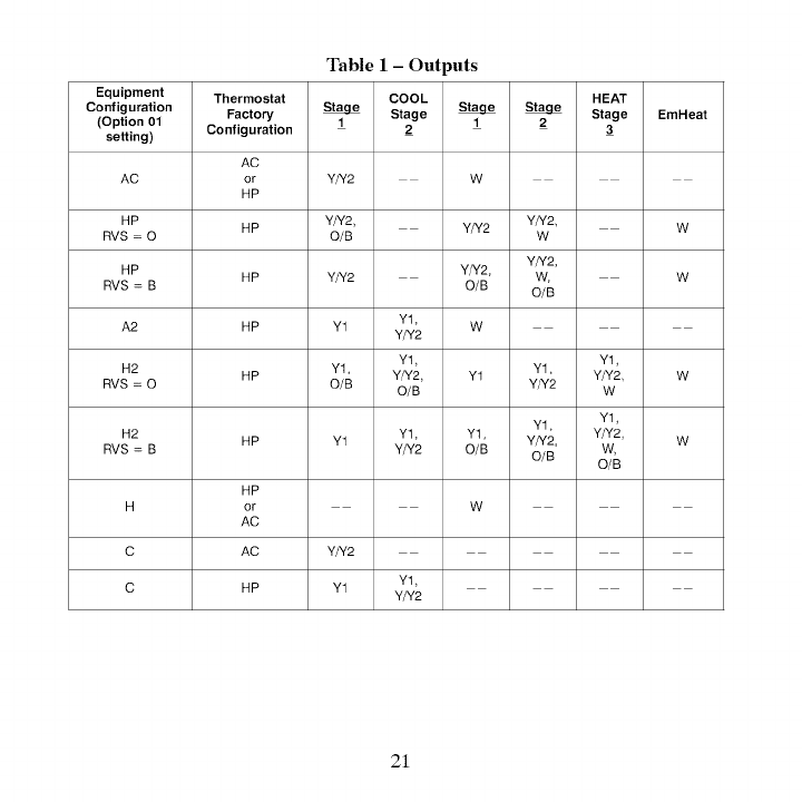
Table 1 -Outputs
Equipment Thermostat COOL HEAT
Configuration _Stage __Stage EmHeat
(Option 01 Factory 1 1 2
setting) Configuration 2 3
AC
AC or Y/Y2 W
HP
HP HP Y/Y2, Y/Y2 Y/Y2 W
RVS = 0 O/B W
Y/Y2,
HP HP Y/Y2 Y/Y2, W, W
RVS = B O/B O/B
A2 HP Y1 Y1. W
Y/Y2
Y1. Y1.
H2 Y1. Y1.
HP Y/Y2, Y1 Y/Y2 W
RVS = 0 O/B O/B Y/Y2 W
Y1. Y1.
H2 HP Y1 Y1. Y1. Y/Y2, Y/Y2, W
RVS = B Y/Y2 O/B O/B W,
O/B
HP
H or W
AC
C AC Y/Y2
C HP Y1 Y1.
Y/Y2
21
Thermostat WIRING DIAGRAMS
Furnace Air Conditioner
Heat
Cool
Fan
24VAC Heating
24VAC Cooling
* Common [_-
* C wire not needed for batteries
A09244
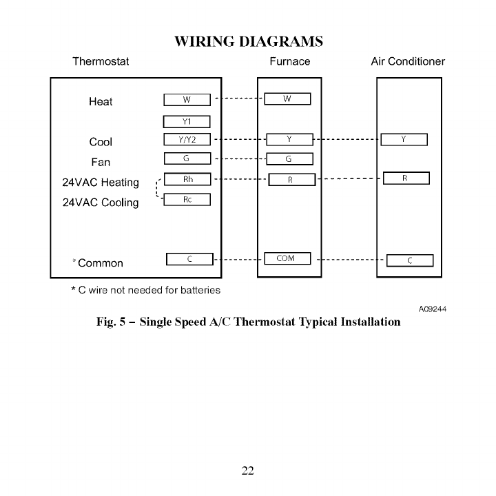
Fig. 5 -Single Speed A/C Thermostat Typical Installation
22
WIRING DIAGRAMS (cont.)
Thermostat Fan Coil Heat Pump
Heat
Cool
Fan
24VAC Heating
24VAC Cooling
*Common ....... _'1 COM ["
*C wire not needed for batteries
............. [_
............ [_
A09245
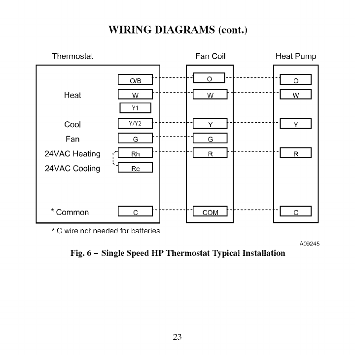
Fig. 6 - Single Speed HP Thermostat Typical Installation
23
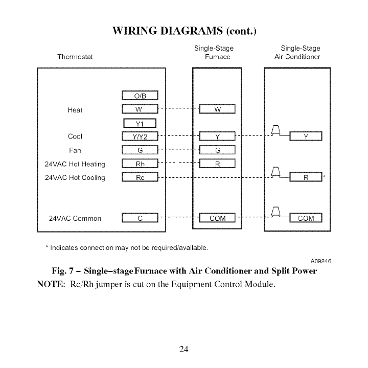
Thermostat
WIRING DIAGRAMS (cont.)
Single-Stage
Furnace Single-Stage
Air Conditioner
Heat
Cool _-
Fan _-
24VAC Hot Heating ['-'--_-
24VAC Hot Cooling _-
24VAC Common _-
-_C:LIZ:::::EZ_
* Indicates connection may not be required/available.
A09246
Fig. 7 -Single-stage Furnace with Air Conditioner and Split Power
NOTE: Rc/Rh jumper is cut on the Equipment Control Module.
24
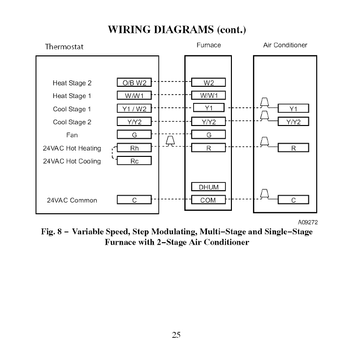
Thermostat
WIRING DIAGRAMS (cont.)
Furnace Air Conditioner
Heat Stage 2
Heat Stage 1
Cool Stage 1
Cool Stage 2
Fan
24VAC Hot Heating
24VAC Hot Cooling
24VAC Common
A09272
Fig. 8 -Variable Speed, Step Modulating, Multi-Stage and Single-Stage
Furnace with 2-Stage Air Conditioner
25
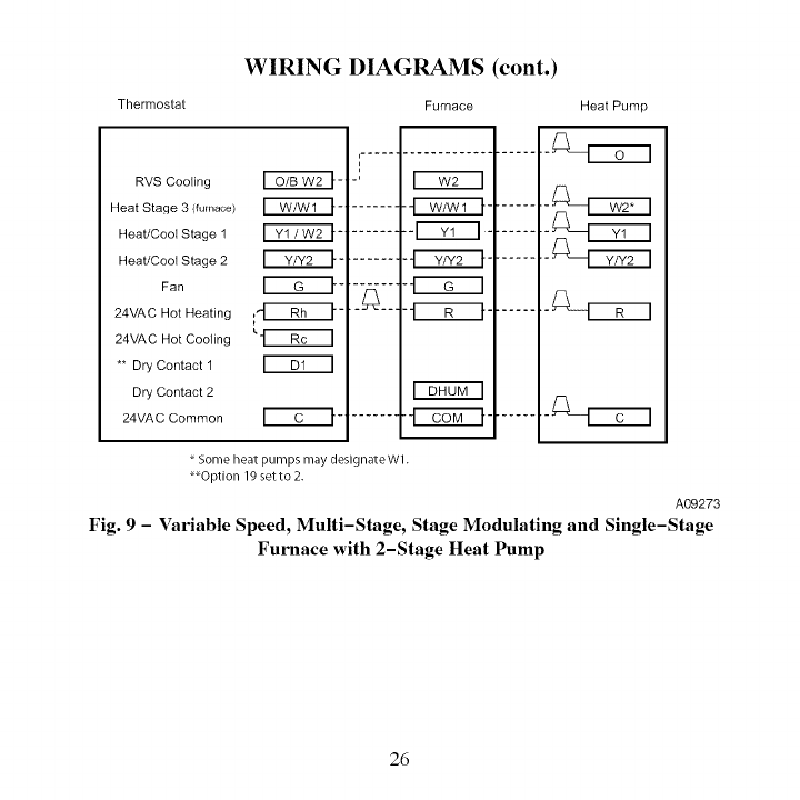
Thermostat
WIRING DIAGRAMS (cont.)
Furnace Heat Pump
RVS Cooling _-'
Heat Stage 3 (furnace) _ -'
Heat/Cool Stage 1 _-
Heat/Cool Stage 2 _-
Fan _-
24VAC Hot Heating
24VAC Hot Cooling
** Dry Contact 1
Dry Contact 2
24VAC Common _'C_I" -'
,.....-m...................
m
tm
-' m
.......
Fs-nonq
Some heat pumps may designate Wl.
_Option 19 setto 2.
A09273
Fig. 9 -Variable Speed, Multi-Stage, Stage Modulating and Single-Stage
Furnace with 2-Stage Heat Pump
26
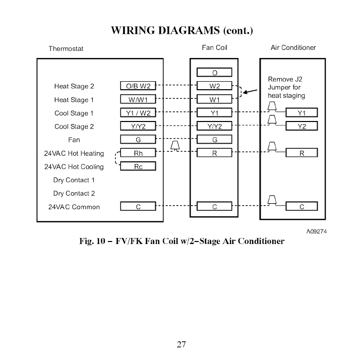
Thermostat
WIRING DIAGRAMS (cont.)
Fan Coil Air Conditioner
Heat Stage 2
Heat Stage 1
Cool Stage 1
Cool Stage 2
Fan
24VAC Hot Heating
24VAC Hot Cooling
Dry Contact 1
Dry Contact 2
24VAC Common
_4111
_.[_--_ _
.i
Remove J2
Jumper for
heat staging
Fig. 10 - FV/FK Fan Coil w/2-Stage Air Conditioner
A09274
27
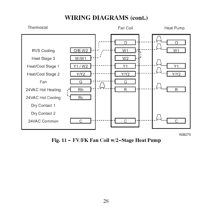
Thermostat
WIRING DIAGRAMS (cont.)
Fan Coil
RVS Cooling
Heat Stage 3
Heat/Cool Stage 1
Heat/Cool Stage 2
Fan
24VAC Hot Heating
24VAC Hot Cooling
Dry Contact 1
Dry Contact 2
24VAC Common
i
i
"ll i' ....
i
i ,J
Heat Pump
Fig. 11 - FV/FK Fan Coil w/2-Stage Heat Pump
A09275
28
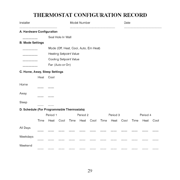
THERMOSTAT CONFIGURATION RECORD
Installer Model Number Date
A. Hardware Configuration
Seal Hole In Wall
B. Mode Settings
Mode (Off, Heat, Cool, Auto Em Heat)
Heating Setpoint Value
Cooling Setpoint Value
Fan (Auto or On)
C. Home, Away, Sleep Settings
Heat Cool
Home
Away
Sleep
D. Schedule (For Programmable Thermostats)
Period 1 Period 2 Period 3 Period 4
Time Heat Cool Time Heat Cool Time Heat Cool Time Heat Cool
All Days
Weekdays
Weekend
29
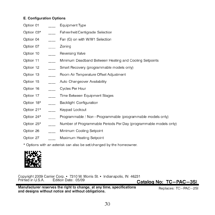
E. Configuration Options
Option 0t __ Equipment Type
Option 03* ____ Fahrenheit/Centigrade Selection
Option 04 __ Fan (G) on with WAN1 Selection
Option 07 __ Zoning
Option 10 __ Reversing Valve
Option 1t __ Minimum Deadband Between Heating and Cooling Setpoints
Option 12 __ Smart Recovery (programmable models only)
Option 13 __ Room Air Temperature Offset Adjustment
Option 15 __ Auto Changeover Availability
Option 16 __ Cycles Per Hour
Option 17 __ Time Between Equipment Stages
Option 18" __ Backlight Configuration
Option 21" __ Keypad Lockout
Option 24* __ Programmable /Non Programmable (programmable models only)
Option 25* __ Number of Programmable Periods Per Day (programmable models only)
Option 26 __ Minimum Cooling Setpoint
Option 27 __ Maximum Heating Setpoint
* Options with an asterisk can also be set/changed by the homeowner.
Copyright 2009 Carrier Corp * 73t0 W Morris St, ° Indianapolis IN 46231
Printed in U.S.A. Edition Date: 05/09 Cataloc I No: TC-PAC-3SI
Manufacturer reserves the right to change, atanytime, specifications Replaces:TC PAC 2SI
and designs without notice and without obligations.
3O
