CARRIER Air Conditioner/heat Pump(outside Unit) Manual L1001418
User Manual: CARRIER CARRIER Air conditioner/heat pump(outside unit) Manual CARRIER Air conditioner/heat pump(outside unit) Owner's Manual, CARRIER Air conditioner/heat pump(outside unit) installation guides
Open the PDF directly: View PDF ![]() .
.
Page Count: 66
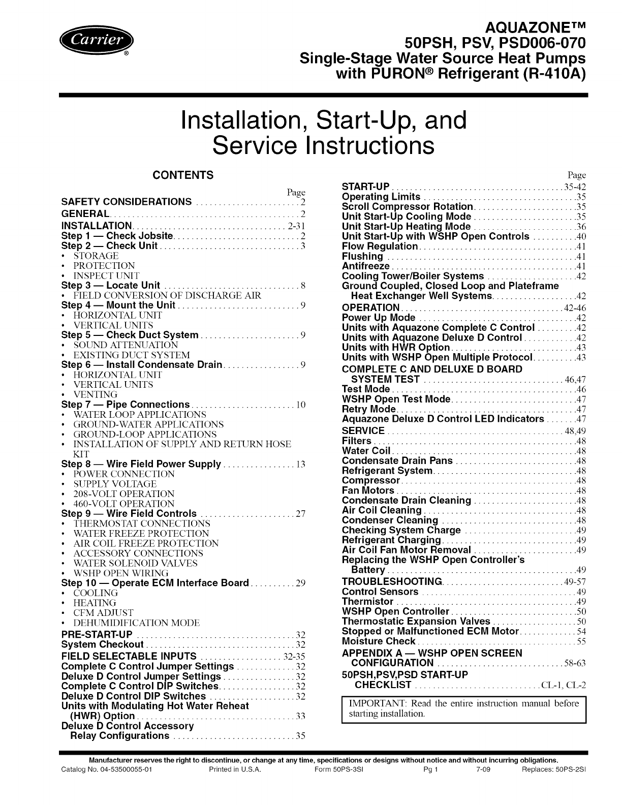
AQUAZONE TM
50PSH, PSV, PSD006-070
Single-Stage Water Source Heat Pumps
with PURON ®Refrigerant (R-410A)
Installation, Start-Up, and
Service Instructions
CONTENTS
Page
SAFETY CONSIDERATIONS ....................... 2
GENERAL .......................................... 2
INSTALLATION .................................. 2-31
Step 1 -- Check Jobsite ............................ 2
Step 2 -- Check Unit ............................... 3
•STORAGE
• PROTECTION
• INSPECT UNIT
Step 3 -- Locate Unit .............................. 8
• FIELD CONVERSION OF DISCHARGE AIR
Step 4 -- Mount the Unit ........................... 9
• HORIZONTAL UNIT
• VERTICAL UNITS
Step 5 -- Check Duct System ...................... 9
• SOUND ATTENUATION
• EXISTING DUCT SYSTEM
Step 6-- Install Condensate Drain ................. 9
• HORIZONTAL UNIT
• VERTICAL UNITS
• VENTING
Step 7 -- Pipe Connections ....................... l0
• WATER LOOP APPLICATIONS
• GROUND-WATER APPLICATIONS
• GROUND-LOOP APPLICATIONS
• INSTALLATION OF SUPPLY AND RETURN HOSE
KIT
Step 8 -- Wire Field Power Supply ................ 13
• POWER CONNECTION
• SUPPLY VOLTAGE
• 208-VOLT OPERATION
• 460-VOLT OPERATION
Step 9 -- Wire Field Controls ..................... 27
• THERMOSTAT CONNECTIONS
• WATER FREEZE PROTECTION
• AIR COIL FREEZE PROTECTION
• ACCESSORY CONNECTIONS
• WATER SOLENOID VALVES
• WSHP OPEN WIRING
Step 10 -- Operate ECM Interface Board .......... 29
•COOLING
• HEATING
• CFM ADJUST
• DEHUMIDIFICATION MODE
PRE-START-U P ................................... 32
System Checkout ................................. 32
FIELD SELECTABLE INPUTS .................. 32-35
Complete C Control Jumper Settings ............. 32
Deluxe D Control Jumper Settings ................ 32
Complete C Control DIP Switches ................. 32
Deluxe D Control DIP Switches ................... 32
Units with Modulating Hot Water Reheat
(HWR) Option ................................... 33
Deluxe D Control Accessory
Relay Configurations ........................... 35
Page
START-UP ...................................... 35-42
Operating Limits .................................. 35
Scroll Compressor Rotation ....................... 35
Unit Start-Up Cooling Mode ....................... 35
Unit Start-Up Heating Mode ....................... 36
Unit Start-Up with WSHP Open Controls .......... 40
Flow Regulation ................................... 41
Flushing .......................................... 41
Antifreeze ......................................... 41
Cooling Tower/Boiler Systems .................... 42
Ground Coupled, Closed Loop and Plateframe
Heat Exchanger Well Systems ................... 42
OPERATION .................................... 42-46
Power Up Mode ................................... 42
Units with Aquazone Complete C Control ......... 42
Units with Aquazone Deluxe D Control ............ 42
Units with HWR Option ............................ 43
Units with WSHP Open Multiple Protocol .......... 43
COMPLETE C AND DELUXE D BOARD
SYSTEM TEST ............................... 46,47
Test Mode ......................................... 46
WSHP Open Test Mode ............................ 47
Retry Mode ........................................ 47
Aquazone Deluxe D Control LED Indicators ....... 47
SERVICE ....................................... 48,49
Filters ............................................. 48
Water Coil ......................................... 48
Condensate Drain Pans ........................... 48
Refrigerant System ................................ 48
Compressor ....................................... 48
Fan Motors ........................................ 48
Condensate Drain Cleaning ....................... 48
Air Coil Cleaning .................................. 48
Condenser Cleaning .............................. 48
Checking System Charge ......................... 49
Refrigerant Charging .............................. 49
Air Coil Fan Motor Removal ....................... 49
Replacing the WSHP Open Controller's
Battery .......................................... 49
TROUBLESHOOTING ........................... 49-57
Control Sensors ................................... 49
Thermistor ........................................ 49
WSHP Open Controller ............................ 50
Thermostatic Expansion Valves ................... 50
Stopped or Malfunctioned ECM Motor ............. 54
Moisture Check .................................... 55
APPENDIX A -- WSHP OPEN SCREEN
CONFIGURATION ............................ 58-63
50PSH,PSV, PSD START-UP
CHECKLIST ............................ CL-I, CL-2
IMPORTANT: Read the entire instruction manual before |
starting installation. 1
Manufacturer reserves the right to discontinue, or change at any time, specifications or designs without notice and without incurring obligations.
Catalog No. 04-53500055-01 Printed in U.S.A. Form 50PS-3SI Pg 1 7-09 Replaces: 50PS-2SI

SAFETY CONSIDERATIONS
Installation and servicing of air-conditioning equipment can
be hazardous due to system pressure and electrical compo-
nents. Only trained and qualified service personnel should
install, repair, or service air-conditioning equipment.
Untrained personnel can perform basic maintenance func-
tions such as cleaning coils and filters and replacing filters. All
other operations should be performed by trained service per-
sonnel. When working on air-conditioning equipment, observe
precautions in the literature, tags and labels attached to the unit,
and other safety precautions that may apply.
Improper installation, adjustment, alteration, service, main-
tenance, or use can cause explosion, fire, electrical shock or
other conditions which may cause personal injury or property
damage. Consult a qualified installer, service agency, or a local
distributor or branch for reformation or assistance. The
qualified installer or agency must use factory-authorized kits or
accessories when modifying this product. Refer to the individ-
ual instructions packaged with the kits or accessories when
installing.
Follow all safety codes. Wear safety glasses and work
gloves. Use quenching cloth for brazing operations. Have fire
extinguisher available. Read these instructions thoroughly and
follow all warnings or cautions attached to the unit. Consult
local building codes and the National Electrical Code (NEC)
for special installation requirements.
Understand the signal words -- DANGER. WARNING,
and CAUTION. DANGER identifies the most serious hazards
which will result in severe personal injury or death.
WARNING signifies hazards that could result in personal iNu-
ry or death. CAUTION is used to identify unsafe practices,
which would result in minor personal injury or product and
property damage.
Recognize safety reformation. This is the safety-alert
symbol (z_k)- When this symbol is displayed on the unit and in
instructions or manuals, be alert to the potential for personal
injury.
Electrical shock can cause personal Njury or death. Before
installing or servicing system, always turn off main power
to system. There may be more than one disconnect switch.
Turn off accessory heater power if applicable.
GENERAL
This installation and start-up instructions literature is for
Aquazone TM single-stage water source heat pump systems.
Water source heat pumps (WSHPs) are single-package hori-
zontally and vertically mounted units with electronic controls
designed for year-round cooling and heating. Aquazone
WSHPs are available in the following unit configurations:
• 50PSH unit with horizontal airflow and right, left or back
discharge
• 50PSV unit with vertical airflow and top discharge
• 50PSD unit with vertical airflow and bottom discharge
(downflow)
IMPORTANT: The installation of water source heat pump
units and all associated components, parts, and accessories
which make up the installation shall be in accordance with
the regulations of ALL authorities having jurisdiction and
MUST conform to all applicable codes. It is the responsi-
bility of the installing contractor to determine and comply
with ALL applicable codes and regulations.
INSTALLATION
Step 1ECheck Jobsite EInstallation, operation and
maintenance instructions are provided with each unit. Before
unit start-up, read all manuals and become familiar with the
unit and its operation. Thoroughly check out the system before
operation. Complete the inspections and instructions listed
below to prepare a unit for installation. See Table 1 for unit
physical data.
IMPORTANT: This equipment is designed for indoor
installation ONLY. Extreme variations in temperature,
humidity and corrosive water or air will adversely affect
the unit performance, reliability and service life.
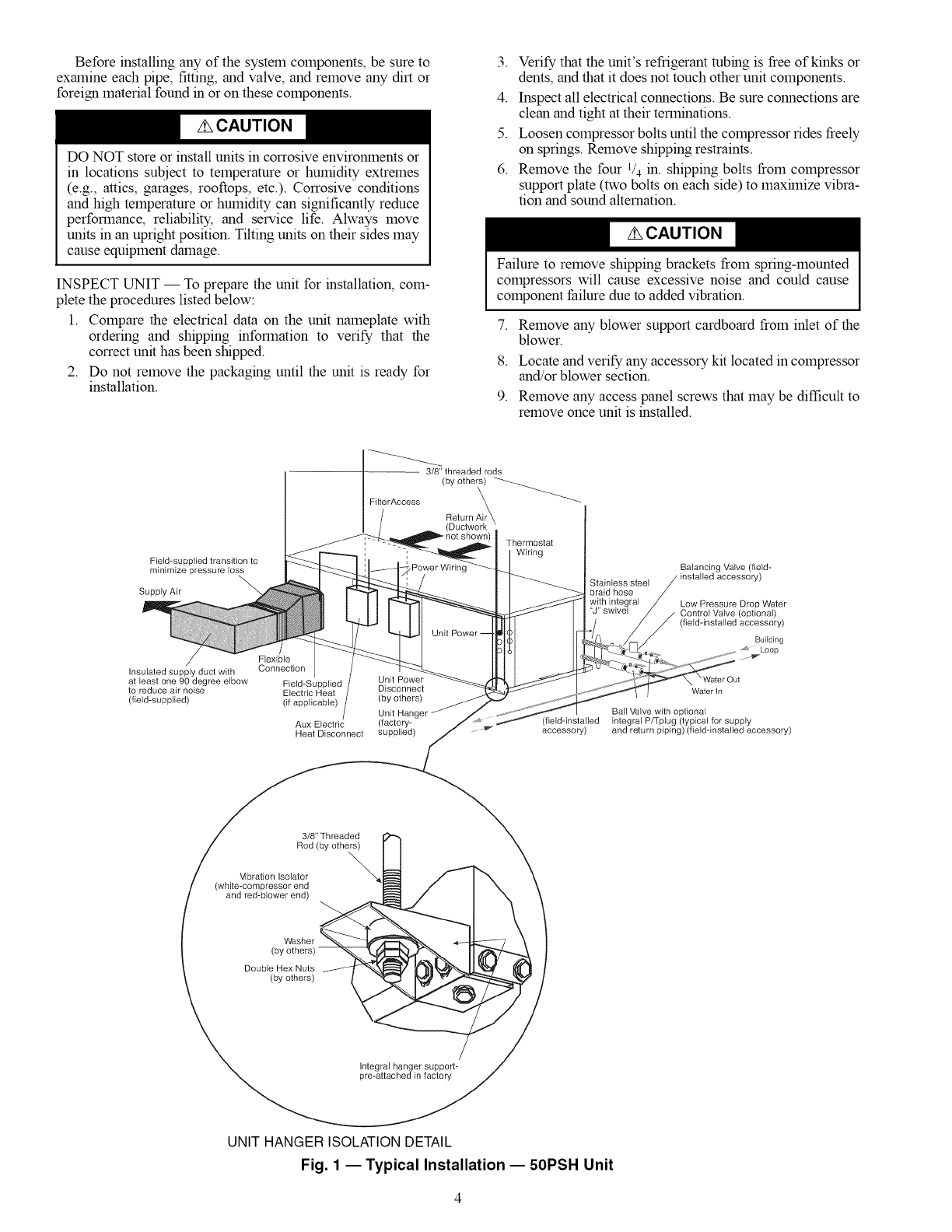
HORIZONTAL UNIT (50PSH) -- Horizontal units are design-
ed for indoor installation only. Be sure to allow adequate space
around the unit for servicing. Ret_r to Fig. 1 for an illustration of
a typical horizontal installation. See Fig. 2 for overall unit
dimensions.
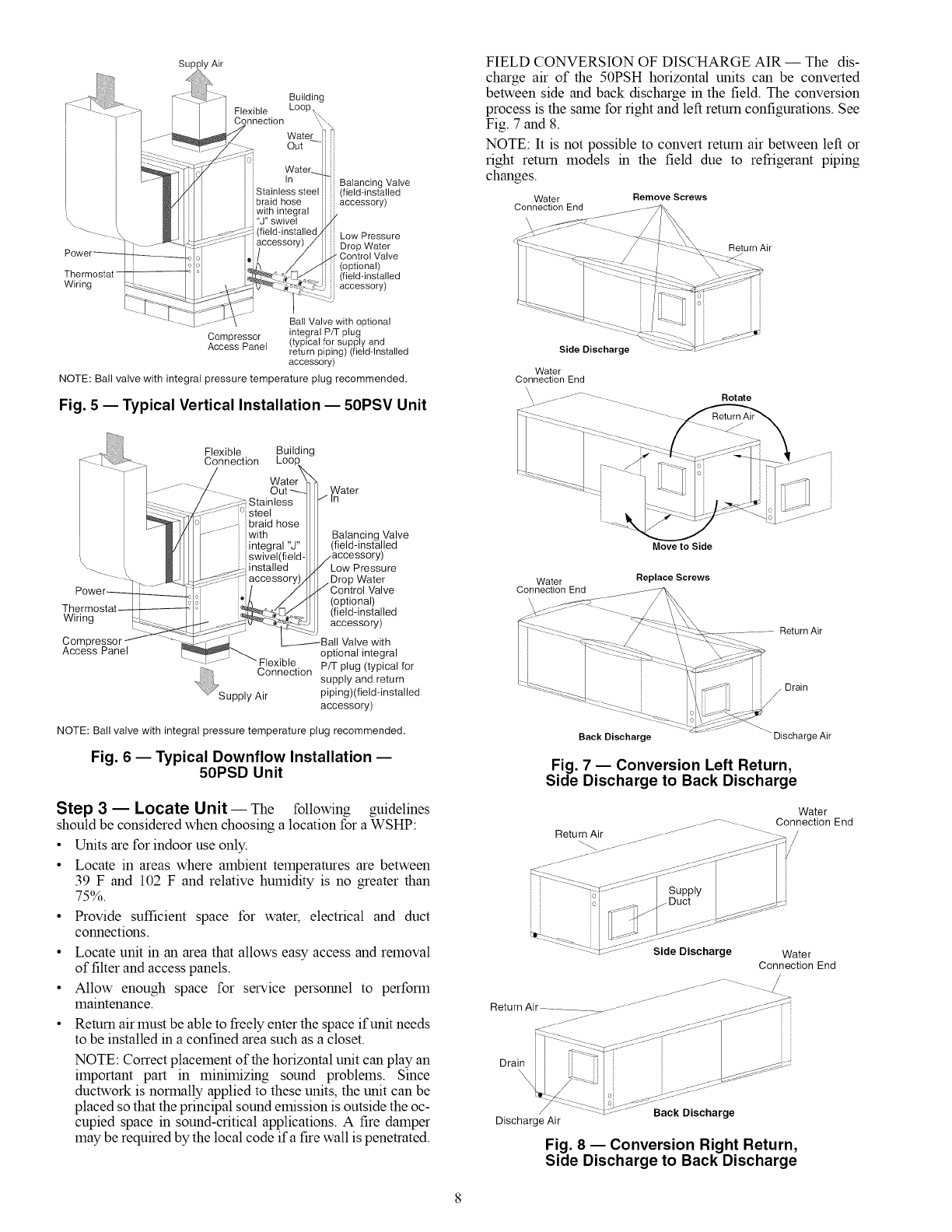
VERTICAL AND DOWNFLOW UNITS (50PSV, PSD) --
Vertical units are designed for indoor installations. While verti-
cal units are typically installed in a floor-level closet or a small
mechanical room, the unit access guidelines for these units are
very similar to those described for horizontal units. See Fig. 3
and 4 for overall dimensions. Refer to Fig. 5 for an example of
a typical vertical installation. Refer to Fig. 6 for a sample
downflow installation.
To avoid equipment damage, do not use these units as a
source of heating or cooling during the construction pro-
cess. The mechanical components and filters used in these
units quickly becomes clogged with construction dirt and
debris which may cause system damage.
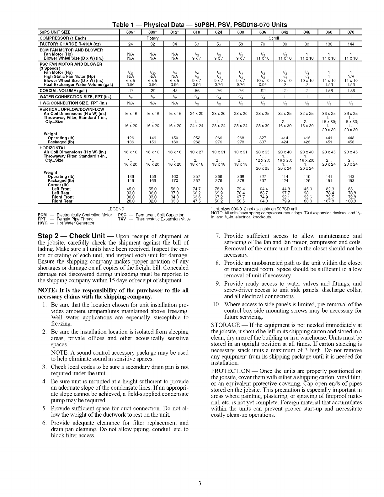
Table 1 -- Physical
50PS UNIT SIZE 006"I oog*I
COMPRESSOR (1 Each) Rotary
FACTORY CHARGE R-410A (oz) 24 32
ECM FAN MOTOR AND BLOWER
Fan Motor (Hp) N/A N/A
Blower Wheel Size (D x W) (in.) N/A N/A
PSC FAN MOTOR AND BLOWER
(3 Speeds)
Fan Motor (Hp) 1/25 1/20
High Static Fan Motor (Hp) N/A N/A
Blower Wheel Size (D x W) (in.) 6 x 5 6 x 5
Heat Exchanger Water Volume (gal.) 0.56 0.56
COAXIAL VOLUME (gal.) .17 .29
WATER CONNECTION SIZE, FPT (in.) 1/2 1/2
HWG CONNECTION SIZE, FPT (in.) N/A N/A
VERTICAL UPFLOW/DOWNFLOW
Air Coil Dimensions (H x W) (in.) 16x16 16x16
Throwaway Filter, Standard 1-in.,
Qty._Size 1_, 1_,
16x20 16x20
Data -- 50PSH, PSV, PSD018-070 Units
9t2" 018 Io24 I989 Io38 Io42 I948 I969 I979
Scroll
34 50 56 58 70 80 80 136 144
N/A 1/2 1/2 1/2 1/2 1/2 1 1 1
N/A 9x7 9x7 9x7 11x10 11x10 11x10 11x10 11x10
1_ l& 1/5 1G 1_ 1_ 3& 1 1
N/A 1_ l& 1_ 1_ 3& 3& 1 N/A
6x5 9x7 9x7 9x7 10x10 10x10 10x10 11x10 11 x10
0.56 0.56 0.76 0.76 0.92 1.24 1.24 1.56 1.56
.45 .56 .76 .76 .92 1.24 1.24 1.56 1.56
1_ 3_ 3/4 3/4 _4 1111
16 x 16 24 x 20 28 x20 28 x 20 28 x 25 32 x 25 32 x 25 36 x 25 36 x 25
1.., 1,.,
1_. 1._ 1_, 1_, 1_, 2_. 2_. 16x30; 16x30;
16 x 20 24 x 24 28 x 24 28 x 24 28 x 30 16 x 30 16 x 30 1.., 1.,
20 x 30 20 x 30
Weight
Operating (Ib) 126 146
Packaged (Ib) 136 156
HORIZONTAL
Air Coil Dimensions (H x W) (in.) 16x16 16x16
Throwaway Filter, Standard 1-in.,
Qty._Size 1_, 1_,
16x20 16x20
Weight
Operating (Ib) 136 156
Packaged (Ib) 146 166
Corner (Ib)
Left Front 45.0 55.0
Left Rear 33,0 36.0
Right Front 30.0 33.0
Right Rear 28.0 32.0
150 252 266 268 327 414 416 441 443
160 262 276 278 337 424 426 451 453
16 x 16 18 x 27 18 x 31 18 x 31 20 x 35 20 x 40 20 x40 20 x 45 20 x 45
1_, 1_. 1_.
1_. 2_. 2_, 2_, 12x 20; 18x20; 18x20; 2._ 2_,
16x20 18x18 18x18 18x18 1,., 1.,. 1.,. 20x24 20x24
20 x 25 20 x 24 20 x 24
160 257 266 268 327 414 416 441 443
170 267 276 278 337 424 426 451 453
56,0 74.7 78.8 79,4 104,4 144.3 145,0 182.3 183.1
37.0 66,2 69.9 70.4 83.7 97.7 98.1 78.4 78.8
34,0 63,6 67.2 67.7 74.9 92.1 92.6 72.5 72.8
33.0 47.5 50.2 50.5 64.0 79.9 80.3 107.8 108.3
LEGEND
ECM -- Electronically Controlled Motor PSC -- Permanent Split Capacitor
FPT -- Female Pipe Thread TXV -- Thermostatic Expansion Valve
HWG -- Hot Water Generator
*Unit sizes 006-012 not available on 50PSD unit.
NOTE: All units have spring compressor mountings, TXV expansion devices, and 1/2-
in. and 3/4-in. electrical knockouts.
Step 2-- Check Unit -- Upon receipt of shipment at
the jobsite, carefully check the shipment against the bill of
lading. Make sure all units have been received. Inspect the car-
ton or crating of each unit, and inspect each unit for damage.
Ensure the shipping company makes proper notation of any
shortages or damage on all copies of the freight bill. Concealed
damage not discovered during unloading must be reported to
the shipping company within 15 days of receipt of shipment.
NOTE: It is the responsibility of the purchaser to file all
necessary claims with the shipping company.
1. Be sure that the location chosen for unit installation pro-
vides ambient temperatures maintained above freezing.
Well water applications are especially susceptible to
freezing.
2. Be sure the installation location is isolated from sleeping
areas, private offices and other acoustically sensitive
spaces.
NOTE: A sound control accessory package may be used
to help eliminate sound in sensitive spaces.
3. Check local codes to be sure a secondary drain pan is not
required under the unit.
4. Be sure unit is mounted at a height sufficient to provide
an adequate slope of the condensate lines. If an appropri-
ate slope cannot be achieved, a field-supplied condensate
pump may be required.
5. Provide sufficient space for duct connection. Do not al-
low the weight of the ductwork to rest on the unit.
6. Provide adequate clearance for filter replacement and
drain pan cleaning. Do not allow piping, conduit, etc. to
block filter access.
7. Provide sufficient access to allow maintenance and
servicing of the fan and fan motor, compressor and coils.
Removal of the entire unit from the closet should not be
necessary.
8. Provide an unobstructed path to the unit within the closet
or mechanical room. Space should be sufficient to allow
removal of unit if necessary.
9. Provide ready access to water valves and fittings, and
screwdriver access to unit side panels, discharge collar,
and all electrical connections.
10. Where access to side panels is limited, pre-removal of the
control box side mounting screws may be necessary for
future servicing.
STORAGE -- If the equipment is not needed ilrnnediately at
the jobsite, it should be left in its shipping carton and stored in a
clean, dry area of the building or in a warehouse. Units must be
stored in an upright position at all tflnes. If carton stacking is
necessary, stack units a maximum of 3 high. Do not remove
any equipment from its shipping package until it is needed for
installation.
PROTECTION -- Once the units are properly positioned on
the jobsite, cover them with either a shipping carton, vinyl fihn,
or an equivalent protective covering. Cap open ends of pipes
stored on the jobsite. This precaution is especially important in
areas where painting, plastering, or spraying of fireproof mate-
rial, etc. is not yet complete. Foreign material that accumulates
within the units can prevent proper start-up and necessitate
costly clean-up operations.
Beforeinstallinganyofthesystemcomponents,besureto
examineeachpipe,fitting,andvalve,andremoveanydirtor
foreignmaterialfoundinoronthesecomponents.
DONOTstoreorinstallunitsincorrosiveenvironmentsor
inlocationssubjecttotemperatureorhumidityextremes
(e.g.,attics,garages,rooftops,etc.).Corrosiveconditions
andhightemperatureorhumiditycansignificantlyreduce
performance,reliability,andservicelife.Alwaysmove
unitsinanuprightposition.Tiltingunitsontheirsidesmay
causeequipmentdamage.
INSPECTUNIT-- Topreparetheunitforinstallation,coln-
pletetheprocedureslistedbelow:
1. Comparetheelectricaldataontheunitnameplatewith
orderingandshippinginformationto verifythatthe
correctunithasbeenshipped.
2. Donotremovethepackaginguntiltheunitisreadyfor
installation.
3. Verifythattheunit'srefrigerantrobingisfreeofkinksor
dents,andthatit doesnottouchotherunitcomponents.
4. Inspectallelectricalconnections.Besureconnectionsare
cleanandtightattheirterminations.
5. Loosencompressorboltsuntilthecompressorridesfreely
onsprings.Removeshippingrestraints.
6. Removethefour1/4in.shippingboltsfromcompressor
supportplate(twoboltsoneachside)tomaxilnizevibra-
tionandsoundalternation.
Failuretoremoveshippingbracketsfromspring-mounted
compressorswill causeexcessivenoiseandcouldcause
componentfailureduetoaddedvibration.
7.
8.
9.
Remove any blower support cardboard froln inlet of the
blower.
Locate and verify any accessory kit located in compressor
and/or blower section.
Remove any access panel screws that may be difficult to
remove once unit is installed.
Field-supplied transition to
minimize pressure loss
\
Supply Air
Flexible
Insulated supply duct with Connection
at least one 90 degree elbow Field-Supplied Unit Power
to reduce air noise Electric Heat Disconnect
(field-supplied) (if applicable) (by others)
Unit Hanger
Aux Electric (factory-
Heat Disconnect supplied)
3/8" threaded rods
(by others) ___
FilterAccess Return
,Power Wiring
Unit
Thermostat
Wiring
(fieldqnstalled
accessory)
Stainless steel
braid hose
Balancing Valve (field-
Y)
Low Pressure Drop Water
Control Valve (optional)
(field-instNled accessory)
Building
Waterln
Ball Valve with optional
integral P/Tplug (typical for supply
and return piping) (field-installed accessory)
3/8" Threaded
Rod (by others)
Vibration Isolator "_
(white-compressor end
and red-blower end)
Double Hex Nuts
(by others)
Integral hanger support-
pre-attached in factory
UNIT HANGER ISOLATION DETAIL
Fig. 1 --Typical Installation- 50PSH Unit
50PSH
UNIT
SIZE
OVERALL
CABINET
(in.)
WATER CONNECTIONS
(in.)
A B C
Width Depth Height
22.4 43.1 17.3
22.4 62.2 19.3
22.4 62.2 19.3
25.4 71.2 21.3
25.4 76.2 21.3
25.4 81.2 21.3
1 2 3 4 5 Loop HWG
Water FPT
D E F G H FPT
In Out HWG HWG Con-
In Out densate
WATER
CONNEC- ELECTRICAL
TIONS (in.) - KNOCKOUTS
UNITS WITH (in.)
HWR
1 2 JK L
112 112 314
Cond Cond Cond
Loop Loop Low Ext Power
In DOut E Voltage Pump Supply
DISCHARGE CONNECTION (in.)
DUCT FLANGE INSTALLED
(-+0.10 in.)
M N OP Q R
(LH Supply Supply (RH
rtrn) Height Width rtrn
RETURN
CONNECTION (in.)
USING RETURN
AIR OPENING
(-+0.10 in.)
S T U V
Return Return
Depth Height
00_2v9,_nn 3.7 9.7 N/A N/A 0.8 1/2 N/A N/A N/A 3.8 6.3 8.8 5.3 4.1 9.0 9.0 5.3 4.1 17.1 15.3 2.1 1.0
018 2.1 10.0 13.9 16.9 0.6 3/4 1/2 2.1 10.0 3.6 6.1 8.6 3.6 2.0 12.5 15.5 3.6 2.0 28.1 16.2 2.3 1.5
024,
030 2.1 10.0 13.9 16.9 0.6 3/4 1/2 5.26 13.13 3.6 6.1 8.6 3.6 2.0 12.5 15.5 3.6 2.0 33.8 16.2 2.3 1.5
036 3.4 10.8 15.6 18.9 0.6 3/4 1/2 5.96 13.13 3.6 6.1 8.6 3.1 1.2 19.0 17.5 3.1 .0 34.8 18.2 3.1 1.5
042,
048 3.4 10.8 15.6 18.9 0.6 1 1/2 5.96 13.13 3.6 6.1 8.6 3.1 1.2 19.0 17.5 3.1 .0 39.8 18.2 3.1 1.5
060, 3.4 10.8 15.6 18.9 0.6 1 1/2 5.96 13.13 3.6 6.1 8.6 3.1 1.2 19.0 17.5 3.1 .0 44.8 18.2 3.1 1.5
O7O
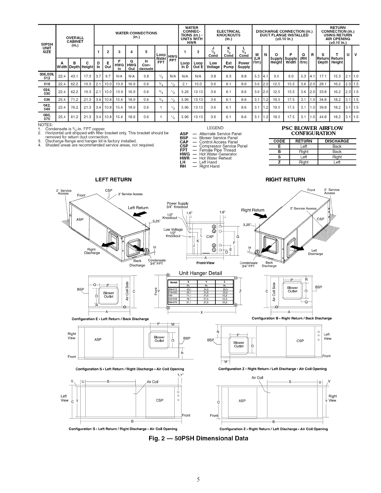
NOTES:
1. Condensate is 3/4-in. FPT copper.
2. Horizontal unit shipped with filter bracket only. This bracket should be
removed for return duct connection.
3. Discharge flange and hanger kit is factory installed.
4. Shaded areas are recommended service areas, not required.
LEGEND
ASP -- Alternate Service Panel
BSP -- Blower Service Panel
CAP -- Control Access Panel
CSP -- Compressor Service Panel
FPT -- Female Pipe Thread
HWG -- Hot Water Generator
HWR -- Hot Water Reheat
LH -- Left Hand
RH -- Right Hand
PSC BLOWER AIRFLOW
CONFIGURATION
CODE RETURN DISCHARGE
ELeft Back
B Right Back
S Left Right
Z Right Left
LEFT RETURN RIGHT RETURN
2' Service CSP
Access 2' ServiceAccess
R*ght _--x.[ ",W Ioltll _"_l_l _
_ Back
Discharge 3/4" FPT
Power Supply
3/4" Knockout
_A_
Front-View
__ _ Unit Hanger Detail
I I= C _Y .......
P _n. _,.
BSP )06-012 43,1 24,5
O _ )18-030 62,1 24,5
]36 71,1 27,5
342-048 76.1 27.5
36O,,070 81,1 27,5
x
Right
View
Front
Configuration E-Left Return /Back Discharge
V
Left _T
View
ASP
Configuration S -Left Return /Right Discharge -Air Coil Opening
1.1"
Ul--S- I jAir CoilCSP !
Front
B_
uration S - Left Return /Right Discharge -Air Coil Opening
Confic
Front 2' Service
Access
1.6" Right Return
3.25-
/
Condensate
3/4" FPT
Back
Discharge
Left
Discharge
in.
20.3
20.3
23.3
23.3
23.3
i
Configuration B-Right Return /Back Discharge
/IB,o e,l CSP
'_M
Configuration Z-Right Return /Left Discharge -Air Coil Opening
cO Left
o:o:
Air Coil
'\ _s I U I /V
Right
ASP T View
i
Configuration Z - Right Return /Left Discharge -Air Coil Opening
Fig. 2 -- 50PSH Dimensional Data
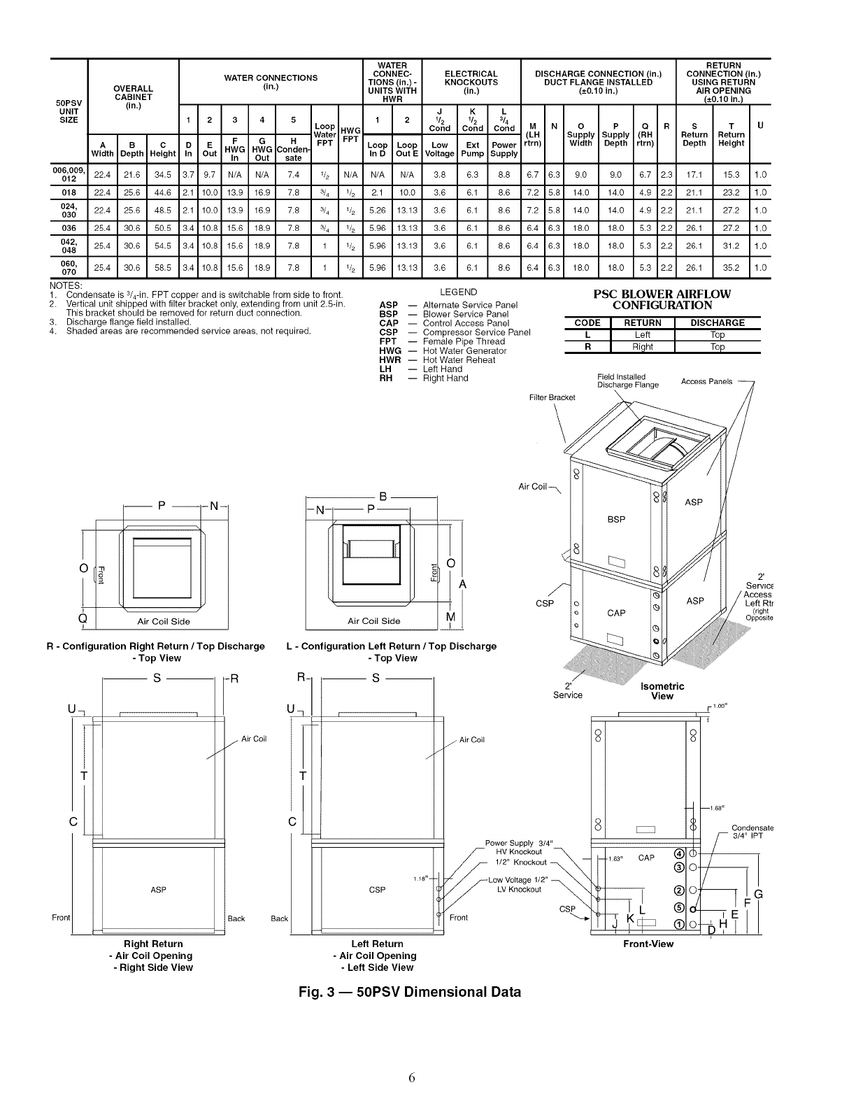
50PSV
UNIT
SIZE
OVERALL
CABINET
(in.)
WATER CONNECTIONS
(in.)
1 2 3 4 5
A B C
Width Depth Height
22.4 21.6 34.5
22.4 25.6 44.6
22.4 25.6 46.5
25.4 30.6 50.5
25.4 30.6 54.5
25.4 30.6 58.5
D E F G H
In Out HWG HWG Conden-
In Out sate
Loop
Water
FPT
HWG
FPT
WATER
CONNEC- ELECTRICAL
TIONS (in.) - KNOCKOUTS
UNITS WITH (in.)
HWR
1 2 J K L
1/2 1/2 3/4
Cond Cond Cond
Loop Loop Low Ext Power
In D Out E Voltage Pump Supply
DISCHARGE CONNECTION (in.)
DUCT FLANGE INSTALLED
(-+0.10 in.)
M N OP Q R
(LH Supply Supply (RH
rtrn) Width Depth rtrn)
RETURN
CONNECTION (in,)
USING RETURN
AIR OPENING
(-+0.10 in.)
ST U
Return Return
Depth Height
00_2vg,_nn 3.7 9.7 N/A N/A 7.4 '/2 N/A N/A N/A 3.8 6.3 8.8 6.7 6.3 9.0 9.0 6.7 2.3 17.1 15.3 1.0
018 2.1 10.0 13.9 16.9 7.8 3/4 1/2 2.1 10.0 3.6 6.1 8.6 7.2 5.8 14.0 14.0 4.9 2.2 21.1 23.2 1.0
024, 2.1 10.0 13.9 16.9 7.8 3/4 1/2 5.26 13.13 3.6 6.1 8.6 7.2 5.8 14.0 14.0 4.9 2.2 21.1 27.2 1.0
030
036 3.4 10.8 15.6 18.9 7.8 3/4 1/2 5.96 13.13 3.6 6.1 8.6 6.4 6.3 18.0 18.0 5.3 2.2 26.1 27.2 1.0
042, 3.4 10.8 15.6 18.9 7.8 1 1/2 5.96 13.13 3.6 6.1 8.6 6.4 6.3 18.0 18.0 5.3 2.2 26.1 31.2 1.0
048
060, 3.4 10.8 15.6 18.9 7.8 1 1/2 5.96 13.13 3.6 6.1 8.6 6.4 6.3 18.0 18.0 5.3 2.2 26.1 35.2 1.0
070
NOTES: LEGEND PSC BLOWER AIRFLOW
CONFIGURATION
1. Condensate is s/4-in. FPT copper and is switchable from side to front.
2. Vertical unit shipped with filter bracket only, extending from unit 2.5-in.
This bracket should be removed for return duct connection.
3. Discharge flange field installed.
4. Shaded areas are recommended service areas, not required.
ASP -- Alternate Service Panel
BSP -- Blower Service Panel
CAP -- Control Access Panel CODE IRETURN IDISCHARGE
CSP -- Compressor Service Panel L ILeft ITop
FPT -- Female Pipe Thread
HWG -- Hot Water Generator RD_hn,V.t 7_,_i.,
HWR -- Hot Water Reheat
LH -- Left Hand
RH -- Right Hand
Filter Bracket
\
FieId Installed
Discharge Flange Access Panels
P
QAir Coil Side
i
B
-N- --P--
/\
\
Air Coil Side
R- Configuration Right Return /Top Discharge L - Configuration Left Return /Top Discharge
- Top View - Top View
S
U_
C
Front
r
_ ASP
Right Return
- Air Coil Opening
- Right Side View
Air Coil-- X
CSP Left Rtr
(right
Opposite
3/4" IPT
Power Supply 3/4"
i
Left Return Front-View
- Air Coil Opening
- Left Side View
Fig. 3-- 50PSV Dimensional Data
WATER RETURN
CONNEC- DISCHARGE CONNECTION (in,) CONNECTION (in.)
WATER CONNECTIONS TIONS (in.) - DUCT FLANGE INSTALLED USING RETURN
OVERALL (in,) UNITS WITH (--.0.10 in.) AIR OPENING
CABINET HWR (-+0.10 in.)
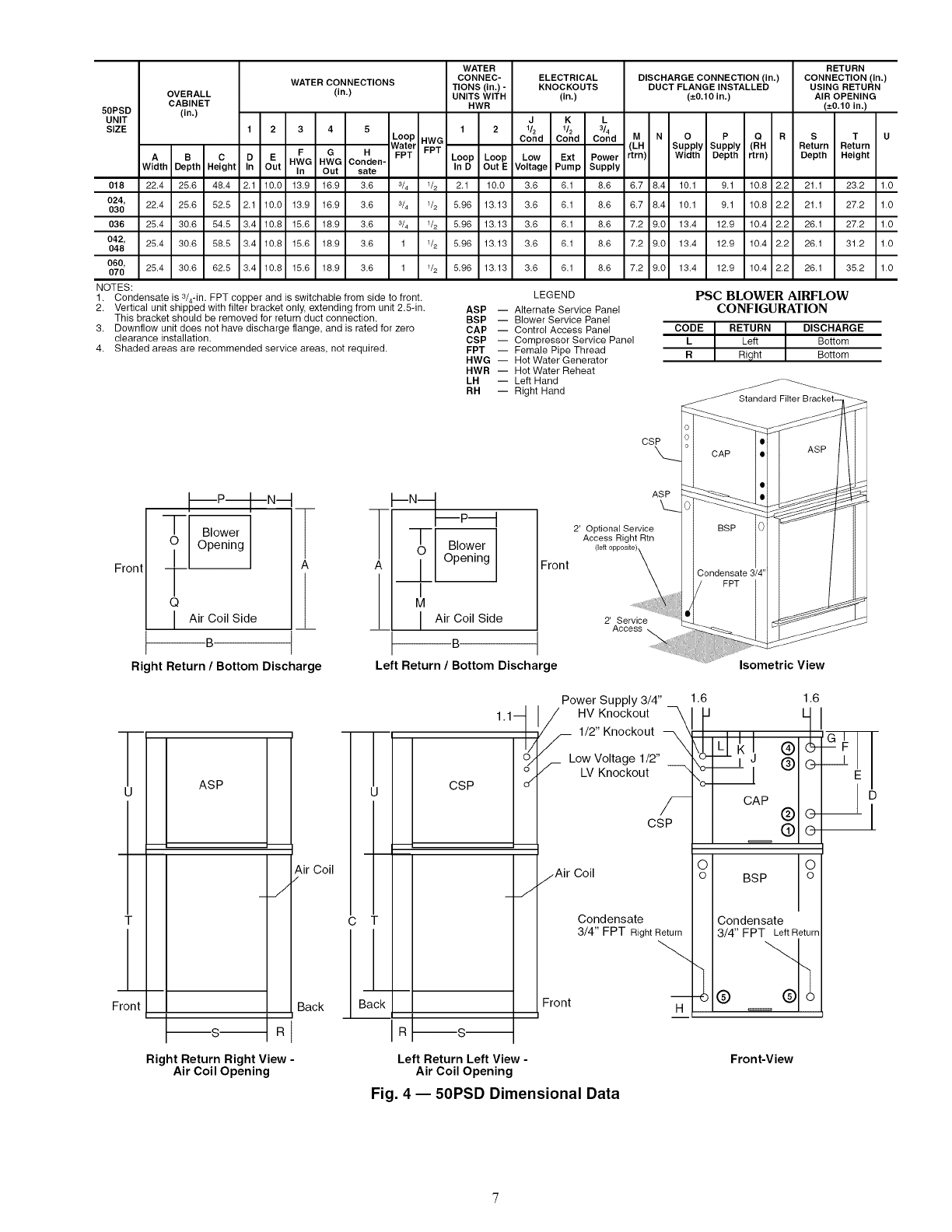
50PSD (in,)
UNIT
SIZE 1 2
Loop HWG
Water FPT
FPT
A B C
Width Depth Height
22.4 25.6 48.4
22.4 25.6 52.5
25.4 30.6 54.5
25.4 30.6 58.5
25.4 30.6 62.5
12 3 4 5
F G H
D E HWG HWG Conden-
In Out In Out sate
21 100 13.9 16.9 3.6
2.1 10.0 13.9 16.9 3.6
3.4 10.8 15.6 18.9 3.6
3.4 10.8 15.6 18.9 3.6
MN O P Q R
(LH Supply Supply (RH
rtrn) Width Depth rtrn)
Loop Loop
In D Out E
2.1 10.0
5.96 13.13
5.96 13.13
5.96 13.13
5.96 13.13
ELECTRICAL
KNOCKOUTS
(in.)
J K L
t& t& 3&
Cond Cond Cond
Low Ext Power
Voltage Pump Supply
3.6 6.1 8.6
3.6 6.1 8.6
3.6 6.1 8.6
3.6 6.1 8.6
3.6 6.1 8.6
STU
Return Return
Depth Height
018 s/4 1/2 6.7 8.4 10.1 9.1 10.8 2.2 21.1 23.2 1.0
024,
030 s/4 1/2 6.7 84 10.1 91 10.8 2.2 21.1 27.2 1.0
036 s/4 1/2 7.2 9.0 13.4 12.9 10.4 2.2 26.1 27.2 1.0
042, 1 1/2 7.2 9.0 13.4 12.9 10.4 2.2 26.1 31.2 1.0
048
060,
070 3.4 10.8 15.6 18.9 3.6 1 1/2 7.2 9.0 13.4 12.9 10.4 2.2 26.1 35.2 1.0
NOTES: LEGEND
ASP -- Alternate Service Panel
BSP -- Blower Service Panel
CAP -- Control Access Panel
CSP -- Compressor Service Panel
FPT -- Female Pipe Thread
HWG -- Hot Water Generator
HWR -- Hot Water Reheat
LH -- Left Hand
RH -- Right Hand
PSC BLOWER AIRFLOW
CONFIGURATION
CODE I RETURN DISCHARGE
L I Left Bottom
RRight Bottom
1. Condensate is s/4-in. FPT copper and is switchable from side to front.
2. Vertical unit shipped with filter bracket only, extending from unit 2.5-in.
This bracket should be removed for return duct connection.
3. Downflow unit does not have discharge flange, and is rated for zero
clearance installation.
4. Shaded areas are recommended service areas, not required.
CSP
Front
ii
)nt
o ;°we;I
Q
I Air Coil Side
B
Right Return /Bottom Discharge
ASP
_J
Right Return Right View -
Air Coil Opening
Air Coil
Back
_--N---_p_
_-- Blower
_ Opening
I
M
I Air Coil Side
B
Left Return /Bottom Discharge
Front
1,1--
ASP
2' Optional Service
Access Right Rtn
(left opposite)
2' Service
Access
Isometric View
i
i I CSP
I
C
Back I
_J
Power Supply 3/4" _ 1.6
HV Knockout
1/2" Knockout --
Low Voltage 1/2"
/-- LV Knockout --
f
CSP
1.6
CAP C
zAirCoi, ? BSP ?
Condensate Condensate
3/4" FPT RightReturn 3/4" FPT Left Return
Front H (_)
Left Return Left View -
Air Coil Opening
Fig. 4 -- 50PSD Dimensional Data
Front-View
Supt _Air
Wiring
Building
Flexible Loop_,
mnection
ou -iiii
Water_i
In i i Balancing Valve
Stainless steel ii (fieldqnstalled
i i accessory)
(field-installed = Low Pressure
Drop Water
Control Valve
(optional)
(field-installed
accessory)
Ball Valve with optional
Compressor integral P/T plug
Access Panel (typical for supply and
return piping) (field-Installed
accessory)
NOTE: Ball valve with integral pressure temperature plug recommended.
Fig. 5 -- Typical Vertical Installation -- 50PSV Unit
FIELD CONVERSION OF DISCHARGE AIR -- The dis-
charge air of the 50PSH horizontal units can be converted
between side and back discharge in the field. The conversion
process is the same for fight and left return configurations. See
Fig. 7 and 8.
NOTE: It is not possible to convert return air between left or
fight return models in the field due to refrigerant piping
changes.
Water Remove Screws
Connection End
Return Air
Side Discharge
Water
Connection End
\\ J---- Rotate
Flexible Building
r::::::::i Connection Loc
Out
Valve
Pow_
Wiring
Compresso_
Access Panel Flexible
Low Pressure
•Drop Water
Control Valve
(optional)
(field-installed
accessory)
Valve with
optional integral
P/T plug (typical for
supply and return
piping)(field-installed
accessory)
NOTE: Ball valve with integral pressure temperature plug recommended.
Fig. 6 -- Typical Downflow Installation --
50PSD Unit
Step 3 -- Locate Unit--The following guidelines
should be considered when choosing a location for a WSHP:
• Units are for indoor use only.
• Locate in areas where ambient temperatures are between
39 F and 102 F and relative humidity is no greater than
75%.
• Provide sufficient space for water, electrical and duct
connections.
• Locate unit in an area that allows easy access and removal
of filter and access panels.
• Allow enough space for service personnel to perform
maintenance.
• Return air must be able to freely enter the space if unit needs
to be installed in a confined area such as a closet.
NOTE: Correct placement of the horizontal unit can play an
important part in minimizing sound problems. Since
ductwork is normally applied to these units, the unit can be
placed so that the principal sound emission is outside the oc-
cupied space in sound-critical applications. A fire damper
may be required by the local code if a fire wall is penetrated.
Move to Side
Water
Connection End
Replace Screws
Return Air
/Drain
/
Back Discharge "Discharge Air
Fig. 7 -- Conversion Left Return,
Side Discharge to Back Discharge
Water
......... Connection End
Return Air
Drain
\
Side Discharge Water
Connection End
------ /
Discharge Air Back Discharge
Fig. 8 -- Conversion Right Return,
Side Discharge to Back Discharge
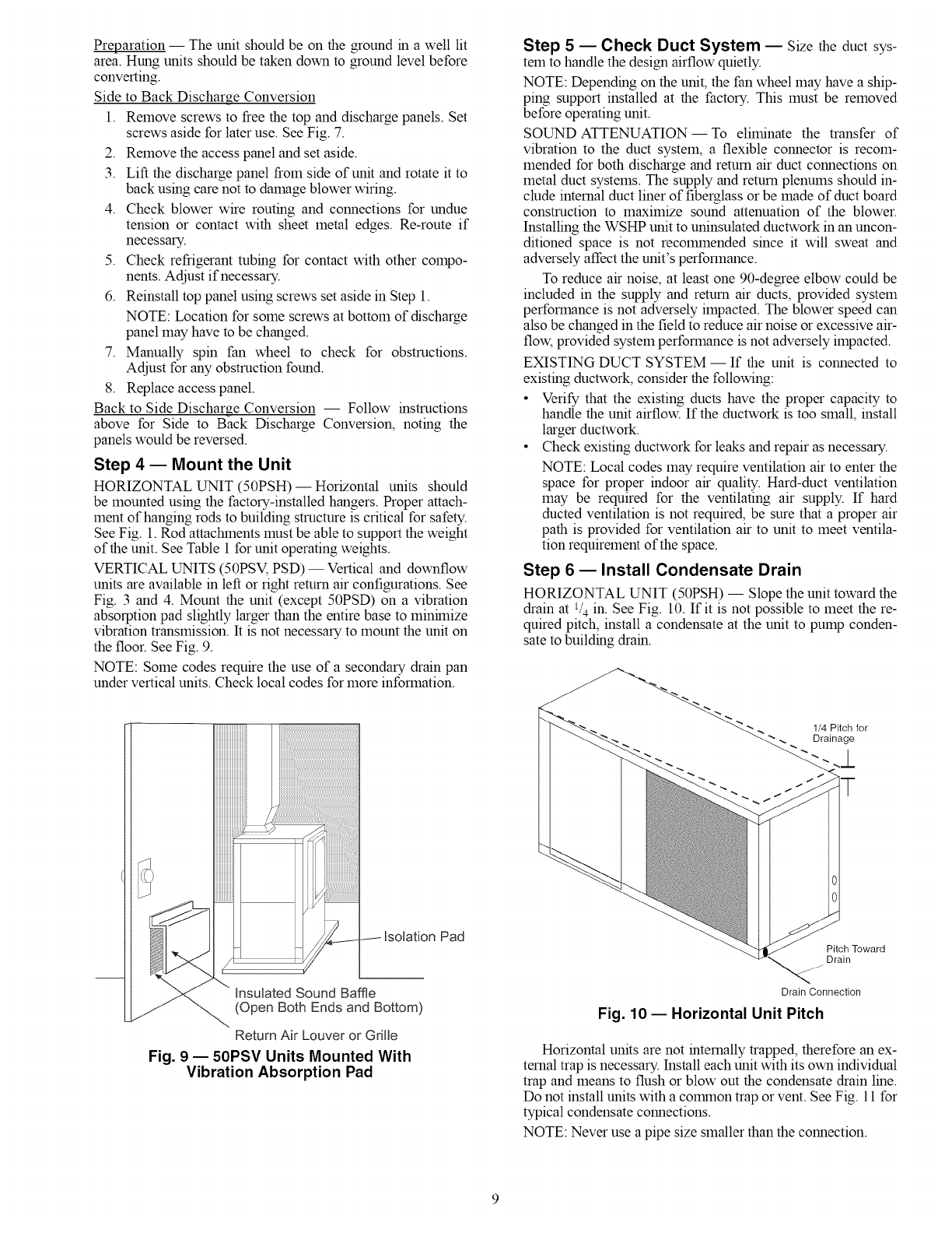
Preparation -- The unit should be on the ground m a well lit
area. Hung units should be taken down to ground level before
converting.
Side to Back Discharge Conversion
1. Remove screws to free the top and discharge panels. Set
screws aside for later use. See Fig. 7.
2. Remove the access panel and set aside.
3. Lift the discharge panel from side of unit and rotate it to
back using care not to damage blower wiring.
4. Check blower wire routing and connections for undue
tension or contact with sheet metal edges. Re-route if
necessary.
5. Check refrigerant tubing for contact with other compo-
nents. Adjust if necessary.
6. Reinstall top panel using screws set aside in Step 1.
NOTE: Location for some screws at bottom of discharge
panel may have to be changed.
7. Manually spin fan wheel to check for obstructions.
Adjust for any obstruction found.
8. Replace access panel.
Back to Side Discharge Conversion -- Follow instructions
above for Side to Back Discharge Conversion, noting the
panels would be reversed.
Step 4 EMount the Unit
HORIZONTAL UNIT (50PSH) -- Horizontal units should
be mounted using the factory-installed hangers. Proper attach-
ment of hanging rods to building structure is critical for safety.
See Fig. 1. Rod attactunents must be able to support the weight
of the unit. See Table 1 for unit operating weights.
VERTICAL UNITS (50PSV, PSD) -- Vertical and downflow
units are available in left or right return air configurations. See
Fig. 3 and 4. Mount the unit (except 50PSD) on a vibration
absorption pad slightly larger than the entire base to minhnize
vibration transmission. It is not necessary to mount the unit on
the floor. See Fig. 9.
NOTE: Some codes require the use of a secondary drain pan
under vertical units. Check local codes for more information.
Return Air Louver or Grille
Fig. 9 -- 50PSV Units Mounted With
Vibration Absorption Pad
Step 5 ECheck Duct System -- Size the duct sys-
temto handle the design airflow quietly.
NOTE: Depending on the unit, the fan wheel may have a ship-
ping support installed at the factory. This must be removed
before operating unit.
SOUND ATTENUATION- To eliminate the transfer of
vibration to the duct system, a flexible connector is recom-
mended for both discharge and return air duct connections on
metal duct systems. The supply and return plenums should in-
clude internal duct liner of fiberglass or be made of duct board
construction to maximize sound attenuation of the blower.
Installing the WSHP unit to uninsulated ductwork in an uncon-
ditioned space is not recolmnended since it will sweat and
adversely affect the unit's performance.
To reduce air noise, at least one 90-degree elbow could be
included in the supply and return air ducts, provided system
performance is not adversely impacted. The blower speed can
also be changed in the field to reduce air noise or excessive air-
flow, provided system performance is not adversely impacted.
EXISTING DUCT SYSTEM- If the unit is connected to
existing ductwork, consider the following:
• Verify that the existing ducts have the proper capacity to
handle the unit airflow. If the ductwork is too small, install
larger ductwork.
• Check existing ductwork for leaks and repair as necessary.
NOTE: Local codes may require ventilation air to enter the
space for proper indoor air quality. Hard-duct ventilation
may be required for the ventilating air supply. If hard
ducted ventilation is not required, be sure that a proper air
path is provided for ventilation air to unit to meet ventila-
tion requirement of the space.
Step 6 -- Install Condensate Drain
HORIZONTAL UNIT (50PSH) -- Slope the unit toward the
drain at l/4 in. See Fig. 10. If it is not possible to meet the re-
quired pitch, install a condensate at the unit to pump conden-
sate to buildmg dram.
Pitch Toward
Drain
...._--
Drain Connection
Fig. 10 -- Horizontal Unit Pitch
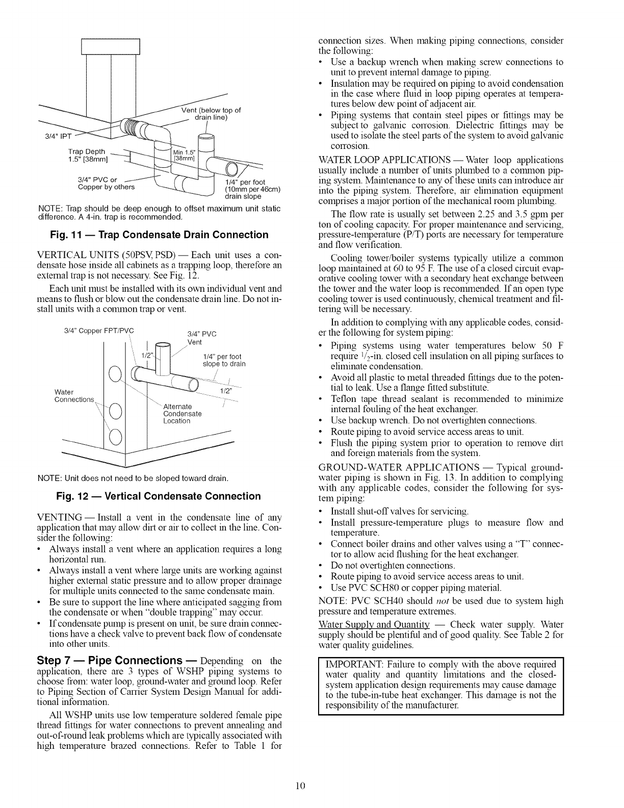
Horizontal units are not internally trapped, therefore an ex-
ternal trap is necessary. Install each unit with its own individual
trap and means to flush or blow out the condensate drain line.
Do not install units with a common trap or vent. See Fig. 11 for
typical condensate connections.
NOTE: Never use a pipe size smaller than the connection.
_p of
drain line)
3/4" IPT ot__
Trap Depth _1.5" _
1.5" [38mm] [38ram] ____
3/4" PVC 1/4" per foot
Copper by others (10mm per 46cm)
drain slope
NOTE: Trap should be deep enough to offset maximum unit static
difference. A 4-in. trap is recommended.
Fig. 11 -- Trap Condensate Drain Connection
VERTICAL UNITS (50PSV,PSD) -- Each unit uses a con-
densate hose inside all cabinets as a trapping loop, therefore an
external trap is not necessary. See Fig. 12.
Each unit must be installed with its own individual vent and
means to flush or blow out the condensate drain line. Do not in-
stall units with a colmnon trap or vent.
3/4" Copper FPT/PVC 3/4" PVC
....' I........ Veot
1/2"I.] I 1/4" per foot
1
Water / "\'-..._.-------_%)'-. !/2 ;'_
Connections 't-¢"q I \" Alternate /
'/k,J/ I Condensate
| I Location
NOTE: Unit does not need to be sloped toward drain.
Fig. 12 -- Vertical Condensate Connection
VENTING- Install a vent in the condensate line of any
application that may allow dirt or air to collect in the line. Con-
sider the following:
• Always install a vent where an application requires a long
horizontal run.
• Always install a vent where large units are working against
higher external static pressure and to allow proper drainage
for multiple units connected to the same condensate main.
• Be sure to support the line where anticipated sagging from
the condensate or when "double trapping" may occur.
• If condensate pump is present on unit, be sure drain connec-
tions have a check valve to prevent back flow of condensate
into other units.
Step 7-- Pipe Connections -- Depending on the
application, there are 3 types of WSHP piping systems to
choose from: water loop, ground-water and ground loop. Refer
to Piping Section of Carrier System Design Manual for addi-
tional information.
All WSHP units use low temperature soldered female pipe
thread fittings for water connections to prevent annealing and
out-of-round leak problems which are typically associated with
high temperature brazed connections. Refer to Table 1 for
connection sizes. When making piping connections, consider
the following:
• Use a backup wrench when making screw connections to
unit to prevent internal damage to piping.
• Insulation may be required on piping to avoid condensation
in the case where fluid in loop piping operates at tempera-
rares below dew point of adjacent air.
• Piping systems that contain steel pipes or fittings may be
subject to galvanic corrosion. Dielectric fittings may be
used to isolate the steel parts of the system to avoid galvanic
corrosion.
WATER LOOP APPLICATIONS -- Water loop applications
usually include a number of units plumbed to a colrnnon pip-
ing system. Maintenance to any of these units can introduce air
into the piping system. Therefore, air elimination equipment
comprises a maior portion of the mechanical room plumbing.
The flow rate is usually set between 2.25 and 3.5 gpm per
ton of cooling capacity. For proper maintenance and servicing,
pressure-temperature (P/T) ports are necessary for temperature
and flow verification.
Cooling tower/boiler systems typically utilize a colmnon
loop maintained at 60 to 95 F. The use of a closed circuit evap-
orative cooling tower with a secondary heat exchange between
the tower and the water loop is recolmnended. If an open type
cooling tower is used continuously, chemical treatment and fil-
tering will be necessary.
In addition to complying with any applicable codes, consid-
er the following for system piping:
• Piping systems using water temperatures below 50 F
require m/2-in,closed cell insulation on all piping surfaces to
eliminate condensation.
• Avoid all plastic to metal threaded fittings due to the poten-
tial to leak. Use a flange fitted substitute.
• Teflon tape thread sealant is recolmnended to minimize
internal fouling of the heat exchanger.
• Use backup wrench. Do not overtighten connections.
• Route piping to avoid service access areas to unit.
• Flush the piping system prior to operation to remove dirt
and foreign materials from the system.
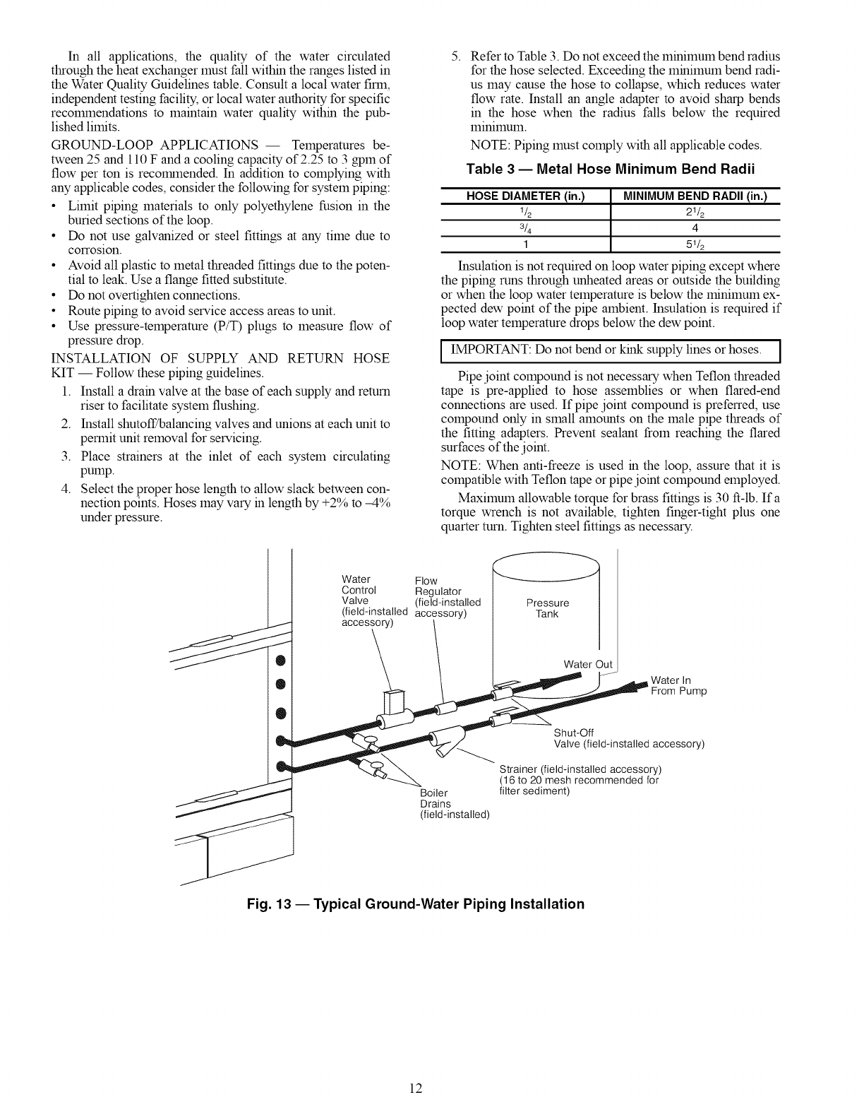
GROUND-WATER APPLICATIONS -- Typical ground-
water piping is shown in Fig. 13. In addition to complying
with any applicable codes, consider the following for sys-
tem piping:
• Install shut-off valves for servicing.
• Install pressure-temperature plugs to measure flow and
temperature.
• Connect boiler drains and other valves using a "T" connec-
tor to allow acid flushing for the heat exchanger.
• Do not overtighten connections.
• Route piping to avoid service access areas to unit.
• Use PVC SCH80 or copper piping material.
NOTE: PVC SCH40 should not be used due to system high
pressure and temperature extremes.
Water Supply and Quantity -- Check water supply. Water
supply should be plentiful and of good quality. See Table 2 for
water quality guidelines.
IMPORTANT: Failure to comply with the above required
water quality and quantity limitations and the closed-
system application design requirements may cause damage
to the robe-in-robe heat exchanger. This damage is not the
responsibility of the manufacturer.
10

Table 2 -- Water Quality Guidelines
CONDITION IHX ICLOSED I
MATERIAL* RECIRCULATING? OPEN LOOP AND RECIRCULATING WELL**
Scaling Potential -- Primary Measurement
Above the given limits, scaling is likely to occur. Scaling indexes should be calculated using the limits below.
0,,Oa,o,omI I I
Hardness Method All N/A pH <7.5 and Ca Hardness, <100 ppm
Index Limits for Probable Scaling Situations (Operation outside these limits is not recommended.)
Scaling indexes should be calculated at 150 F for direct use and HWG applications, and at 90 F for indirect HX use. A monitoring plan should be
implemented.
6.0 - 7.5
Ryznar Stability Index All N/A If >7.5 minimize steel pipe use.
Langelier Saturation Index -0.5 to +0.5
All N/A If <-0.5 minimize steel pipe use.
Based upon 150 F HWG and direct well, 85 F indirect well HX.
Iron Fouling
Iron Fe 2+ (Ferrous) <0.2 ppm (Ferrous)
(Bacterial Iron Potential) All N/A If Fe 2+ (ferrous) >0.2 ppm with pH 6 - 8, 02<5 ppm check for iron bacteria.
Iron Fouling All N/A <0.5 ppm of Oxygen
Above this level deposition will occur.
Corrosion Preventiontt
6 - 8.5 6 - 8.5
pH All Monitor/treat as needed. Minimize steel pipe below 7 and no open tanks with pH <8.
Hydrogen Sulfide (H2S) <0.5 ppm
All N/A At H2S>0.2 ppm, avoid use of copper and cupronickel piping of HXs.
Rotten egg smell appears at 0.5 ppm level.
Copper alloy (bronze or brass) cast components are okay to <0.5 ppm.
Ammonia Ion as Hydroxide, <0.5 ppm
Chloride, Nitrate and Sulfate All N/A
Compounds
Maximum Chloride Levels
Copper
Cupronickel
304 SS
316 SS
Titanium
N/A
N/A
N/A
N/A
N/A
Maximum allowable at maximum water temperature.
50 F (10 C) 75 F (24 C) 100 F (38 C)
<20 ppm NR NR
<150 ppm NR NR
<400 ppm <250 ppm <150 ppm
<1000 ppm <550 ppm <375 ppm
>1000 ppm >550 ppm >375 ppm
Erosion and Clogging
Particulate Size and Erosion <10 ppm of particles and a <10 ppm (<1 ppm "sandfree" for reinjection) of particles and a maximum
All maximum velocity of 6 fps. velocity of 6 fps. Filtered for maximum 800 micron size. Any particulate that
Filtered for maximum
800 micron size. is not removed can potentially clog components.
Brackish Use cupronickel heat exchanger when concentrations of calcium or sodium
All N/A chloride are greater than 125 ppm are present. (Seawater is approximately
25,000 ppm.)
LEGEND
HWG -- Hot Water Generator
HX -- Heat Exchanger
N/A -- Design Limits Not Applicable Considering Recirculating
Potable Water
NR -- Application Not Recommended
SS -- Stainless Steel
*Heat exchanger materials considered are copper, cupronickel, 304 SS
(stainless steel), 316 SS, titanium.
tCIosed recirculating system is identified by a closed pressurized piping
system.
**Recirculating open wells should observe the open recirculating design
considerations.
ttlf the concentration of these corrosives exceeds the maximum allow-
able level, then the potential for serious corrosion problems exists.
Sulfides in the water quickly oxidize when exposed to air, requiring that
no agitation occur as the sample is taken. Unless tested immediately
at the site, the sample will require stabilization with a few drops of one
Molar zinc acetate solution, allowing accurate sulfide determination up
to 24 hours after sampling. A low pH and high alkalinity cause system
problems, even when both values are within ranges shown. The term
pH refers to the acidity, basicity, or neutrality of the water supply.
Below 7.0, the water is considered to be acidic. Above 7.0, water is
considered to be basic. Neutral water contains a pH of 7.0.
To convert ppm to grains per gallon, divide by 17. Hardness in mg/I is
equivalent to ppm.
1!
In all applications, the quality of the water circulated
through the heat exchanger must fall within the ranges listed in
the Water Quality Guidelines table. Consult a local water firm,
independent testing facility, or local water authority for specific
recolmnendations to maintain water quality within the pub-
lished limits.
GROUND-LOOP APPLICATIONS -- Temperatures be-
tween 25 and 110 F and a cooling capacity of 2.25 to 3 gpm of
flow per ton is recommended. In addition to complying with
any applicable codes, consider the following for system piping:
• Limit piping materials to only polyethylene fusion in the
buried sections of the loop.
• Do not use galvanized or steel fittings at any time due to
corrosion.
• Avoid all plastic to metal threaded fittings due to the poten-
tial to leak. Use a flange fitted substitute.
• Do not overtighten connections.
• Route piping to avoid service access areas to unit.
• Use pressure-temperature (P/T) plugs to measure flow of
pressure drop.
INSTALLATION OF SUPPLY AND RETURN HOSE
KIT -- Follow these piping guidelines.
1. Install a dram valve at the base of each supply and return
riser to facilitate system flushing.
2. Install shutoff/balancing valves and unions at each unit to
permit unit removal for servicing.
3. Place strainers at the inlet of each system circulating
pump.
4. Select the proper hose length to allow slack between con-
nection points. Hoses may vary m length by +2% to -4%
under pressure.
5. Refer to Table 3. Do not exceed the minimum bend radius
for the hose selected. Exceeding the minimum bend radi-
us may cause the hose to collapse, which reduces water
flow rate. Install an angle adapter to avoid sharp bends
in the hose when the radius falls below the required
lllinilllUlI1.
NOTE: Piping must comply with all applicable codes.
Table 3 -- Metal Hose Minimum Bend Radii
HOSE DIAMETER (in.) MINIMUM BEND RADII (in.)
1/2 21/2
3/4 4
1 51/2
Insulation is not required on loop water piping except where
the piping runs through unheated areas or outside the building
or when the loop water temperature is below the mimmum ex-
pected dew point of the pipe ambient. Insulation is required if
loop water temperature drops below the dew point.
IMPORTANT: Do not bend or kink supply lines or hoses. ]
I
Pipe joint compound is not necessary when Teflon threaded
tape is pre-applied to hose assemblies or when flared-end
connections are used. If pipe joint compound is preferred, use
compound only in small amounts on the male pipe threads of
the fitting adapters. Prevent sealant from reaching the flared
surfaces of the joint.
NOTE: When anti-freeze is used m the loop, assure that it is
compatible with Teflon tape or pipe joint compound employed.
Maximum allowable torque for brass fittings is 30 ft-Ib. Ifa
torque wrench is not available, tighten finger-tight plus one
quarter turn. Tighten steel fittings as necessary.
Water Flow
Control Regulator
Valve (field-installed Pressure I
(field-installed accessory) Tank I
_ accessory) 1 /
0 \ \ WaterOut
_ ; .---_:__ /...... .,,Jh_Water In
.._- _ _ Shut-Off
_ IJ_P___ve (field-installedaccessory)
_ _ _ Stra;_ield-installed accessory)
/(16 to 20 meshrecommendedfor
Boiler filter sediment)
Drains
(field-installed)
Fig. 13 -- Typical Ground-Water Piping Installation
12
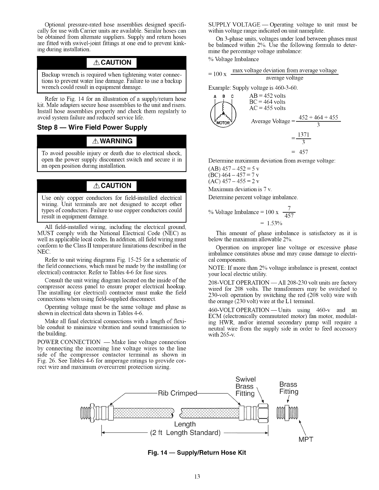
Optional pressure-rated hose assemblies designed specifi-
cally for use with Carrier units are available. Similar hoses can
be obtained from alternate suppliers. Supply and return hoses
are fitted with swivel-ioint fittings at one end to prevent kink-
ing during installation.
Backup wrench is required when tightening water connec-
tions to prevent water line damage. Failure to use a backup
wrench could result in equipment damage.
Refer to Fig. 14 for an illustration of a supply/return hose
kit. Male adapters secure hose assemblies to the unit and risers.
Install hose assemblies properly and check them regularly to
avoid system failure and reduced service life.
Step 8 EWire Field Power Supply
To avoid possible injury or death due to electrical shock,
open the power supply disconnect switch and secure it in
an open position during installation.
Use only copper conductors for field-installed electrical
wiring. Unit terminals are not designed to accept other
types of conductors. Failure to use copper conductors could
result in equipment damage.
All field-installed wiring, including the electrical ground,
MUST comply with the National Electrical Code (NEC) as
well as applicable local codes. In addition, all field wiring must
conform to the Class II temperature limitations described in the
NEC.
Refer to unit wiring diagrams Fig. 15-25 for a schematic of
the field connections, which must be made by the installing (or
electrical) contractor. Refer to Tables 4-6 for fuse sizes.
Consult the unit wiring diagram located on the inside of the
compressor access panel to ensure proper electrical hookup.
The installing (or electrical) contractor must make the field
connections when using field-supplied disconnect.
Operating voltage must be the same voltage and phase as
shown in electrical data shown in Tables 4-6.
Make all final electrical connections with a length of flexi-
ble conduit to minimize vibration and sound transmission to
the building.
POWER CONNECTION -- Make line voltage connection
by connecting the incoming line voltage wires to the line
side of the compressor contactor terminal as shown in
Fig. 26. See Tables 4-6 for amperage ratings to provide cor-
rect wire and maximum overcurrent protection sizing.
Rib Crimped.
SUPPLY VOLTAGE- Operating voltage to unit must be
within voltage range indicated on unit nameplate.
On 3-phase units, voltages under load between phases must
be balanced within 2%. Use the following formula to deter-
mine the percentage voltage hnbalance:
% Voltage hnbalance
= 100 x max voltage deviation from average voltage
average voltage
Example: Supply voltage is 460-3-60.
A B C AN = 452 volts
BC = 464 volts
AC = 455 volts
Average Voltage - 452 + 464 + 455
3
1371
3
= 457
Determine maximum deviation from average voltage:
(AB) 457 - 452 = 5 v
(BC) 464 - 457 = 7 v
(AC) 457 - 455 = 2 v
Maximum deviation is 7 v.
Determine percent voltage hnbalance.
7
% Voltage hnbalance = 100 x 457
= 1.53%
This amount of phase imbalance is satisfactory as it is
below the maxflnum allowable 2%.
Operation on hnproper line voltage or excessive phase
imbalance constitutes abuse and may cause damage to electri-
cal components.
NOTE: If more than 2% voltage hnbalance is present, contact
your local electric utility.
208-VOLT OPERATION- All 208-230 volt units are factory
wired for 208 volts. The transformers may be switched to
230-volt operation by switching the red (208 volt) wire with
the orange (230 volt) wire at the L1 terminal.
460-VOLT OPERATION-- Units using 460-v and an
ECM (electronically colmnutated motor) fan motor, modulat-
ing HWtL and/or internal secondary pump will require a
neutral wire from the supply side in order to feed accessory
with 265-v.
Swivel
Brass Brass
,_iitting '_ Fitting
Length
(2 ft Length Standard)
Fig. 14- Supply/Return Hose Kit
\
MPT
13
SEE NO_Eb
TY_mAL
T_TAT
Y_
Y_--
oO-- ;
G(_--
R_)---
C_--
×l(_-,
SEE NOTE 6
FOR DRY
ALARM CONTACT
I SEE
SEE
NOTE 6
CONTROL BOX LAYOUT
SEE NOTE D _ NO
EXTERNAL T"[_ _ROU:
HW G ..... I E
PUMP ASTAT L--. _0T WAT R
, DTS 8LK _ii GENERATOR*
RED POWER SUPPLY
r i_l CONDUCIORS ONLY
.--I SEE NOTE 2 AND 8
SEE NOTE 9
iYEL OR WRT DRN
,I
DR "_ __, G!Y
! IFCTRY SETTING MED)
REFER TO DATA PLATE
POWER SUPPLY
USE COPPER
CONDUCTORS ONLY.
•.--_ ........
LEGEND
AL -- Alarm Relay Contacts
ASTAT -- Aquastat
BR -- Blower Relay
CB -- Circuit Breaker
CO -- Compressor Contactor
CO -- Condensate Overflow Sensor
COMPR -- Compressor
DTS -- Discharge Temp Switch
FP1 -- Water Coil Freeze Protection Sensor
FP2 -- Air Coil Freeze Protection Sensor
HP -- High-Pressure Switch
HWG -- Hot Water Generator
JW -- Jumper Wire
LOC -- Loss of Charge Pressure Switch
MV -- Motorized Valve
NEC -- National Electrical Code
PSC -- Permanent Split Capacitor
P1 -- Field Wiring Terminal Block
RVS -- Reversing Valve Solenoid
TRANS --
UPS
42>
@
*Optional.
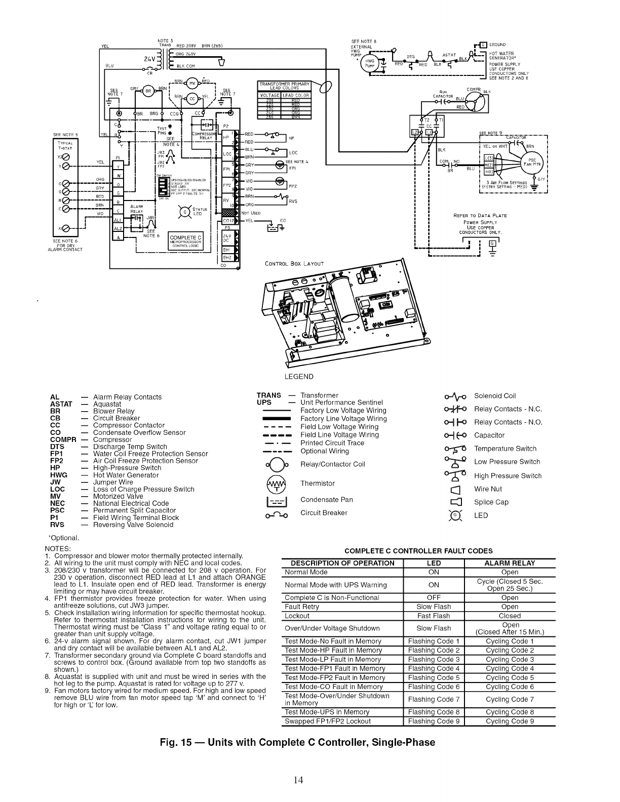
NOTES:
1. Compressor and blower motor thermally protected internally.
2. All wiring to the unit must comply with NEC and local codes.
3. 208/230 v transformer will be connected for 208 v operation. For
230 v operation, disconnect RED lead at L1 and attach ORANGE
lead to L1. Insulate open end of RED lead. Transformer is energy
limiting or may have circuit breaker.
4. FP1 thermistor provides freeze protection for water. When using
antifreeze solutions, cut JW3 jumper.
5. Check installation wiring information for specific thermostat hookup.
Refer to thermostat installation instructions for wiring to the unit.
Thermostat wiring must be "Class 1" and voltage rating equal to or
greater than unit supply voltage.
6. 24-v alarm signal shown. For dry alarm contact, cut JWl jumper
and dry contact will be available between ALl and AL2.
7. Transformer secondary ground via Complete C board standoffs and
screws to control box. (Ground available from top two standoffs as
shown.)
8. Aquastat is supplied with unit and must be wired in series with the
hot leg to the pump. Aquastat is rated for voltage up to 277 v.
9. Fan motors factory wired for medium speed. For high and low speed
remove BLU wire from fan motor speed tap 'M' and connect to 'H'
for high or IZ for low.
Transformer
Unit Performance Sentinel
Factory Low Voltage Wiring
Factory Line Voltage Wiring
Field Low Voltage Wiring
Field Line Voltage Wiring
Printed Circuit Trace
Optional Wiring
Relay/Contactor Coil
Thermistor
Condensate Pan
Circuit Breaker
Solenoid Coil
Relay Contacts - N.C.
O_ I,,,O Relay Contacts - N.O.
O_ _O Capacitor
Temperature Switch
O'_ Low Pressure Switch
O'_ High Pressure Switch
Wire Nut
I_ Splice Cap
_(_ LED
COMPLETE C CONTROLLER FAULT CODES
DESCRIPTION OF OPERATION LED ALARM RELAY
Normal Mode ON Open
Cycle (Closed 5 Sec.
Normal Mode with UPS Warning ON Open 25 Sec.)
Complete C is Non-Functional OFF Open
Fault Retry Slow Flash Open
Lockout Fast Flash Closed
Over/Under Voltage Shutdown Slow Flash Open
(Closed After 15 Min.)
Test Mode-No Fault in Memory Flashing Code 1 Cycling Code 1
Test Mode-HP Fault in Memory Flashing Code 2 Cycling Code 2
Test Mode-LP Fault in Memory Flashing Code 3 Cycling Code 3
Test Mode-FP1 Fault in Memory Flashing Code 4 Cycling Code 4
Test Mode-FP2 Fault in Memory Flashing Code 5 Cycling Code 5
Test Mode-CO Fault in Memory Flashing Code 6 Cycling Code 6
Test Mode-Over/Under Shutdown Flashing Code 7 Cycling Code 7
in Memory
Test Mode-UPS in Memory Flashing Code 8 Cycling Code 8
Swapped FP1/FP2 Lockout Flashing Code 9 Cycling Code 9
Fig. 15 -- Units with Complete C Controller, Single-Phase
14
_ .?.MP.E_ETA%_ __YEL
CTMF_ ?_f_'GF -- --
FA,_ GRY
za wc R_D
C.._ON BRN
AL.g.... _7
SEE_OTE 6 _o_
DRYC_NT_CTOR ALARM
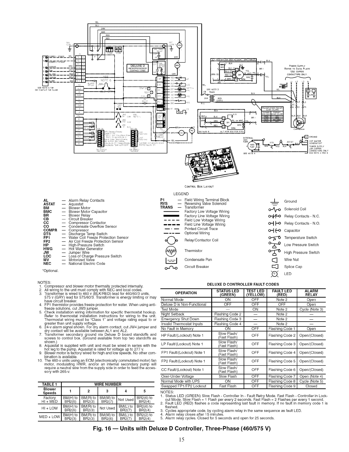
AL -- Alarm Relay Contacts
ASTAT -- Aquastat
BM -- Blower Motor
BMC -- Blower Motor Capacitor
BR -- Blower Relay
CB -- Circuit Breaker
CC -- Compressor Contactor
CO -- Condensate Overflow Sensor
COMPR -- Compressor
DTS -- Discharge Temp Switch
FP1 -- Water Coil Freeze Protection Sensor
FP2 -- Air Coil Freeze Protection Sensor
HP -- High-Pressure Switch
HWG -- Hot Water Generator
JW -- Jumper Wire
LOC -- Loss of Charge Pressure Switch
MV -- Motorized Valve
NEC -- National Electric Code
*Optional.
NOTES:
1. Compressor and blower motor thermally protected internally.
2. All wiring to the unit must comply with NEC and local codes.
3. Transformer is wired to 460 v (BLK/RED) lead for 460/60/3 units,
575 v (GRY) lead for 575/60/3. Transformer is energy limiting or may
have circuit breaker.
4. FP1 thermistor provides freeze protection for water. When using anti-
freeze solutions, cut JW3 jumper.
5. Check installation wiring information for specific thermostat hookup.
Refer to thermostat installation instructions for wiring to the unit.
Thermostat wiring must be "Class 1" and voltage rating equal to or
greater than unit supply voltage.
6. 24-v alarm signal shown. For dry alarm contact, cut JW4 jumper and
dry contact will be available between ALl and AL2.
7. Transformer secondary ground via Deluxe D board standoffs and
screws to control box. (Ground available from top two standoffs as
shown.)
8. Aquastat is supplied with unit and must be wired in series with the
hot leg to the pump. Aquastat is rated for voltage up to 277 v.
9. Blower motor is factory wired for high and low speeds. No other com-
bination is available.
10. The 460-v units using an ECM (electronically commutated motor) fan
motor, modulating HWR, and/or an internal secondary pump will
require a neutral wire from the supply side in order to feed the acces-
sory with 265-v.
TABLE 1 WIRE NUMBER
Blower
SDeeds 12 3 4 5
!
Factory BM(H) to BM(R) to BM(M) to BR2(6) to
HI + MED BR2(6) BR2(3) BR2(7) Not Used BR2(4)
BM(H) to BM(R) to BM(L) to BR2(6) to
HI + LOW BR2(6) BR2(3) Not Used BR2(7) BR2(4)
BM(H) to BM(R) to BM(M) to BM(L) to BR2(2) to
MED + LOW BR2(3) BR2(3) aN2(6) BR2(7) aN2(4)
CONTROL BOX LAYOUT
LEGEND
P1 -- Field Wiring Terminal Block
RVS -- Reversing Valve Solenoid
TRANS -- Transformer
Factory Low Voltage Wiring
Factory Line Voltage Wiring
Field Low Voltage Wiring
Field Line Voltage Wiring
._ Printed Circuit Trace
Optional Wiring
oO o Relay/Contactor Coil
Thermistor
Condensate Pan
o.=r%.o Circuit Breaker
__L_ Ground
OJ_ Solenoid Coil
Relay Contacts - N.C.
O_ _ Relay Contacts - N.O.
O_ _-O Capacitor
Temperature Switch
O'_ Low Pressure Switch
O_ High Pressure Switch
I_ Wire Nut
E_ Splice Cap
_O_ LED
OPERATION
Normal Mode
Deluxe D is Non-Functional
Test Mode
Night Setback
Emergency Shut Down
Invalid Thermostat Inputs
No Fault in Memory
HP Fault/(Leckeut) Note 1
LP Fault/(Leckout) Note 1
FP1 Fault/(Leckeut) Note 1
FP2 Fault/(Lockeut) Note 1
CC Fault/(Leckout) Note 1
Over-Under Voltage
Normal Mode with UPS
Swapped FP1/FP2 Lockout
NOTES:
DELUXE D CONTROLLER FAULT CODES
STATUS LED TEST LED FAULT LED
(GREEN) (YELLOW) (RED)
ON OFF Note 2
OFF OFF OFF
-- ON Note 2
Flashing Code 2 -- Note 2
Flashing Code 3 -- Note 2
Flashing Code 4 -- Note 2
ON OFF Flashing Code 1
Slow Flash/
(Fast Flash) OFF Flashing Code 2
Slow Flash/
(Fast Flash) OFF Flashing Code 3
Slow Flash/
(Fast Flash) OFF Flashing Code 4
Slow Flash/
(Fast Flash) OFF Flashing Code 5
Slow Flash/
(Fast Flash) OFF Flashing Code 6
Slow Flash OFF Flashing Code 7
ON OFF Flashing Code 8
Fast Flash OFF Flashing Code 9
ALARM
RELAY
Open
Open
Cycle (Note 3)
Open
Open/(Closed)
Open/(Closed)
Open/(Closed)
Open/(Closed)
Open/(Closed)
Open (Note 4)
Cycle (Note 5)
Closed
1. Status LED (GREEN) Slow Flash - Controller In - Fault Retry Mode. Fast Flash - Controller in Lock-
out Mode. Slow Flash = 1 Flash per every 2 seconds. Fast Flash = 2 Flashes per every 1 second.
2. Fault LED (RED) flashes a code representing last fault in memory, If no fault in memory code 1 is
flashed.
3. Cycles appropriate code, by cycling alarm relay in the same sequence as fault LED.
4. Alarm relay closes after 15 minutes.
5. Alarm relay cycles. Closed for 5 seconds and open for 25 seconds.
Fig. 16 -- Units with Deluxe D Controller, Three-Phase (460/575 V)
15
I
ICONTROL BOX LAYOUT
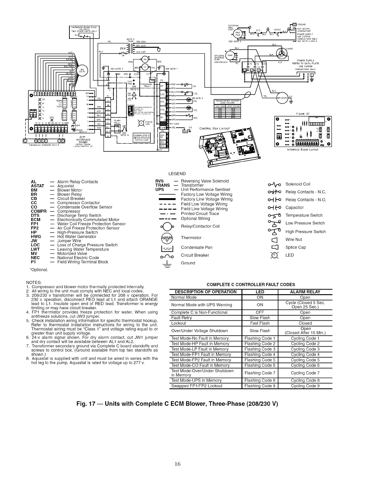
AL -- Alarm Relay Contacts
ASTAT -- Aquastat
BM -- Blower Motor
BR -- Blower Relay
CB -- Circuit Breaker
CO -- Compressor Contactor
CO -- Condensate Overflow Sensor
COMPR -- Compressor
DTS -- Discharge Temp Switch
ECM -- Electronically Commutated Motor
FP1 -- Water Coil Freeze Protection Sensor
FP2 -- Air Coil Freeze Protection Sensor
HP -- High-Pressure Switch
HWG -- Hot Water Generator
JW -- Jumper Wire
LOC -- Loss of Charge Pressure Switch
LWT -- Leaving Water Temperature
MV -- Motorized Valve
NEC -- National Electric Code
P1 -- Field Wiring Terminal Block
*Optional.
LEGEND
RVS -- Reversing Valve Solenoid
TRANS -- Transformer
UPS -- Unit Performance Sentinel
Factory Low Voltage Wiring
Factory Line Voltage Wiring
Field Low Voltage Wiring
Field Line Voltage Wiring
• _ Printed Circuit Trace
Optional Wiring
o(_ Relay/Contactor Coil
Thermistor
_ Condensate Pan
O.=,'_=O Circuit Breaker
__L_ Ground
OJ_ Solenoid Coil
Relay Contacts - N.C.
0"=4_ Relay Contacts - N.O.
O_ _O Capacitor
Temperature Switch
Low Pressure Switch
O'_ High Pressure Switch
I_ Wire Nut
E_ Splice Cap
_(_ LED
NOTES:
1. Compressor and blower motor thermally protected internally.
2. All wiring to the unit must comply with NEC and local codes.
3. 208/230 v transformer will be connected for 208 v operation. For
230 v operation, disconnect RED lead at L1 and attach ORANGE
lead to L1. Insulate open end of RED lead. Transformer is energy
limiting or may have circuit breaker.
4. FP1 thermistor provides freeze protection for water. When using
antifreeze solutions, cut JW3 jumper.
5. Check installation wiring information for specific thermostat hookup.
Refer to thermostat installation instructions for wiring to the unit.
Thermostat wiring must be "Class 1" and voltage rating equal to or
greater than unit supply voltage.
6. 24-v alarm signal shown. For dry alarm contact, cut JW1 jumper
and dry contact will be available between ALl and AL2.
7. Transformer secondary ground via Complete C board standoffs and
screws to control box. (Ground available from top two standoffs as
shown.)
8. Aquastat is supplied with unit and must be wired in series with the
hot leg to the pump. Aquastat is rated for voltage up to 277 v.
COMPLETE C CONTROLLER FAULT CODES
DESCRIPTION OF OPERATION LED ALARM RELAY
Normal Mode ON Open
Cycle (Closed 5 Sec.
Normal Mode with UPS Warning ON Open 25 Sec.)
Complete C is Non-Functional OFF Open
Fault Retry Slow Flash Open
Lockout Fast Flash Closed
Open
Over/Under Voltage Shutdown Slow Flash (Closed After 15 Min.)
Test Mode-No Fault in Memory Flashing Code 1 Cycling Code 1
Test Mode-HP Fault in Memory Flashing Code 2 Cycling Code 2
Test Mode-LP Fault in Memory Flashing Code 3 Cycling Code 3
Test Mode-FP1 Fault in Memory Flashing Code 4 Cycling Code 4
Test Mode-FP2 Fault in Memory Flashing Code 5 Cycling Code 5
Test Mode-CO Fault in Memory Flashing Code 6 Cycling Code 6
Test Mode-Over/Under Shutdown
in Memory Flashing Code 7 Cycling Code 7
Test Mode-UPS in Memory Flashing Code 8 Cycling Code 8
Swapped FP1/FP2 Lockout Flashing Code 9 Cycling Code 9
Fig. 17 -- Units with Complete C ECM Blower, Three-Phase (208/230 V)
ld
LQi ii' o
H
LO_WOR_S rROTOCOk
l
LEGEND
TO eROU._
J
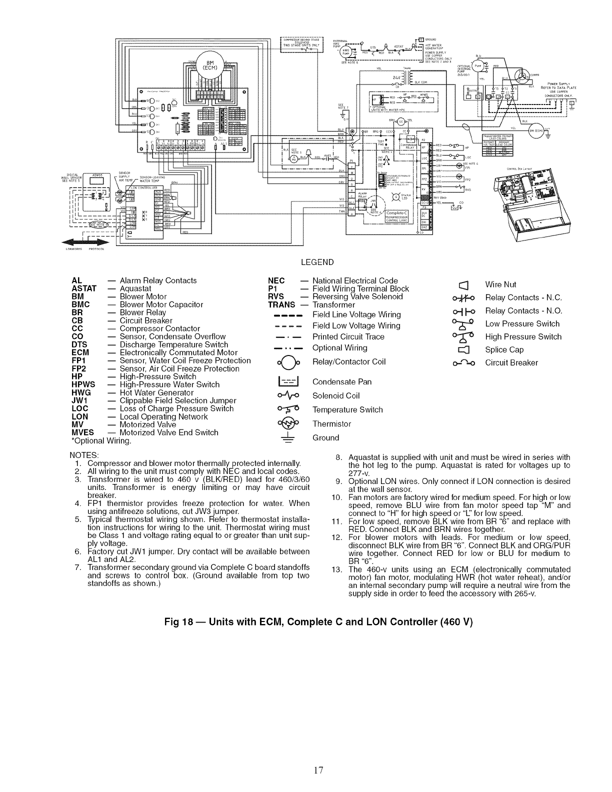
AL -- Alarm Relay Contacts
ASTAT -- Aquastat
BM -- Blower Motor
BMC -- Blower Motor Capacitor
BR -- Blower Relay
CB -- Circuit Breaker
CC -- Compressor Contactor
CO -- Sensor, Condensate Overflow
DTS -- Discharge Temperature Switch
ECM -- Electronically Commutated Motor
FP1 -- Sensor, Water Coil Freeze Protection
FP2 -- Sensor, Air Coil Freeze Protection
HP -- High-Pressure Switch
HPWS -- High-Pressure Water Switch
HWG -- Hot Water Generator o..tV,o
JWl -- Clippable Field Selection Jumper
LOC -- Loss of Charge Pressure Switch
LON -- Local Operating Network
MV -- Motorized Valve
MVES -- Motorized Valve End Switch _L
*Optional Wiring.
NEC -- National Electrical Code
P1 -- Field Wiring Terminal Block
RVS -- Reversing Valve Solenoid
TRANS -- Transformer
Field Line Voltage Wiring
Field Low Voltage Wiring
Printed Circuit Trace
Optional Wiring
Relay/Contactor Coil
Condensate Pan
Solenoid Coil
Temperatu re Switch
Thermistor
Ground
I_ Wire Nut
Relay Contacts - N.C.
o_ _ Relay Contacts- N.O.
Low Pressure Switch
High Pressure Switch
E:_ Splice Cap
o.--"_.-o Circuit Breaker
NOTES:
1. Compressor and blower motor thermally protected internally.
2. All wiring to the unit must comply with NEC and local codes.
3. Transformer is wired to 460 v (BLK/RED) lead for 460/3/60
units. Transformer is energy limiting or may have circuit
breaker.
4. FP1 thermistor provides freeze protection for water. When
using antifreeze solutions, cut JW3 jumper.
5. Typical thermostat wiring shown. Refer to thermostat installa-
tion instructions for wiring to the unit. Thermostat wiring must
be Class 1 and voltage rating equal to or greater than unit sup-
ply voltage.
6. Factory cut JWl jumper. Dry contact will be available between
ALl and AL2.
7. Transformer secondary ground via Complete C board standoffs
and screws to control box. (Ground available from top two
standoffs as shown.)
8. Aquastat is supplied with unit and must be wired in series with
the hot leg to the pump. Aquastat is rated for voltages up to
277-v.
9. Optional LON wires. Only connect if LON connection is desired
at the wall sensor.
10. Fan motors are factory wired for medium speed. For high or low
speed, remove BLU wire from fan motor speed tap "M" and
connect to "H" for high speed or '1" for low speed.
11. For low speed, remove BLK wire from BR "6" and replace with
RED. Connect BLK and BRN wires together.
12. For blower motors with leads. For medium or low speed,
disconnect BLK wire from BR "6". Connect BLK and ORG/PUR
wire together. Connect RED for low or BLU for medium to
BR "6".
13. The 460-v units using an ECM (electronically commutated
motor) fan motor, modulating HWR (hot water reheat), and/or
an internal secondary pump will require a neutral wire from the
supply side in order to feed the accessory with 265-v.
Fig 18 -- Units with ECM, Complete C and LON Controller (460 V)
17

LEGEND
AL -- Alarm Relay Contacts
ASTAT -- Aquastat
BM -- Blower Motor
BMC -- Blower Motor Capacitor
BR -- Blower Relay
CB -- Circuit Breaker
CC -- Compressor Contactor -- •--
CO -- Sensor, Condensate Overflow
DTS -- Discharge Temperature Switch
ECM -- Electronically Commutated Motor
FP1 -- Sensor, Water Coil Freeze Protection
FP2 -- Sensor, Air Coil Freeze Protection I___1
HP -- High-Pressure Switch Lz.zJ
HPWS -- High-Pressure Water Switch o..zV,o
HWG -- Hot Water Generator
JWl -- Clippable Field Selection Jumper
LOC -- Loss of Charge Pressure Switch _,_,=
LON -- Local Operating Network
MV -- Motorized Valve _L
NEC -- National Electrical Code ---
*Optional Wiring.
P1 -- Field Wiring Terminal Block
RVS -- Reversing Valve Solenoid
TRANS -- Transformer
Field Line Voltage Wiring
Field Low Voltage Wiring
Printed Circuit Trace
Optional Wiring
Relay/Contactor Coil
Condensate Pan
Solenoid Coil
Temperature Switch
Thermistor
Ground
I_ Wire Nut
Relay Contacts - N.C.
o_ _:_ Relay Contacts - N.O.
Low Pressure Switch
High Pressure Switch
Splice Cap
o-'%-o Circuit Breaker
NOTES:
1. Compressor and blower motor thermally protected internally.
2. All wiring to the unit must comply with NEC and local codes.
3. Transformer is wired to 460 v (BLK/RED) lead for 460/3/60
units. Transformer is energy limiting or may have circuit
breaker.
4. FP1 thermistor provides freeze protection for water. When
using antifreeze solutions, cut JW3 jumper.
5. Typical thermostat wiring shown. Refer to thermostat installa-
tion instructions for wiring to the unit. Thermostat wiring must
be Class 1 and voltage rating equal to or greater than unit sup-
ply voltage.
6. Factory cut JWl jumper. Dry contact will be available between
ALl and AL2.
7. Transformer secondary ground via Deluxe D board standoffs
and screws to control box. (Ground available from top two
standoffs as shown.)
8. Aquastat is supplied with unit and must be wired in series with
the hot leg to the pump. Aquastat is rated for voltages up to
277-v.
9. Blower motor is factory wired for medium and high speeds. For
any other combination of speeds, at the motor attach the BLK
wire to the higher of the two desired speed taps and the BLU
wire to the lower of the two desired speed taps.
10. Optional LON wires. Only connect if LON connection is desired
at the wall sensor.
11. Blower motor is factory wired for high and low speeds. No other
combination is available.
12. The 460-v units using an ECM (electronically commutated
motor) fan motor, modulating HWR (hot water reheat), and/or
an internal secondary pump will require a neutral wire from the
supply side in order to feed the accessory with 265-v.
Fig 19 -- Units with ECM, Deluxe D and LON Controller (460 V)
18
......1/ L
-iii
LEGEND
¢:
.q,I
14:,
i_;_:_%_7a_ i ...........o_o0o,po0
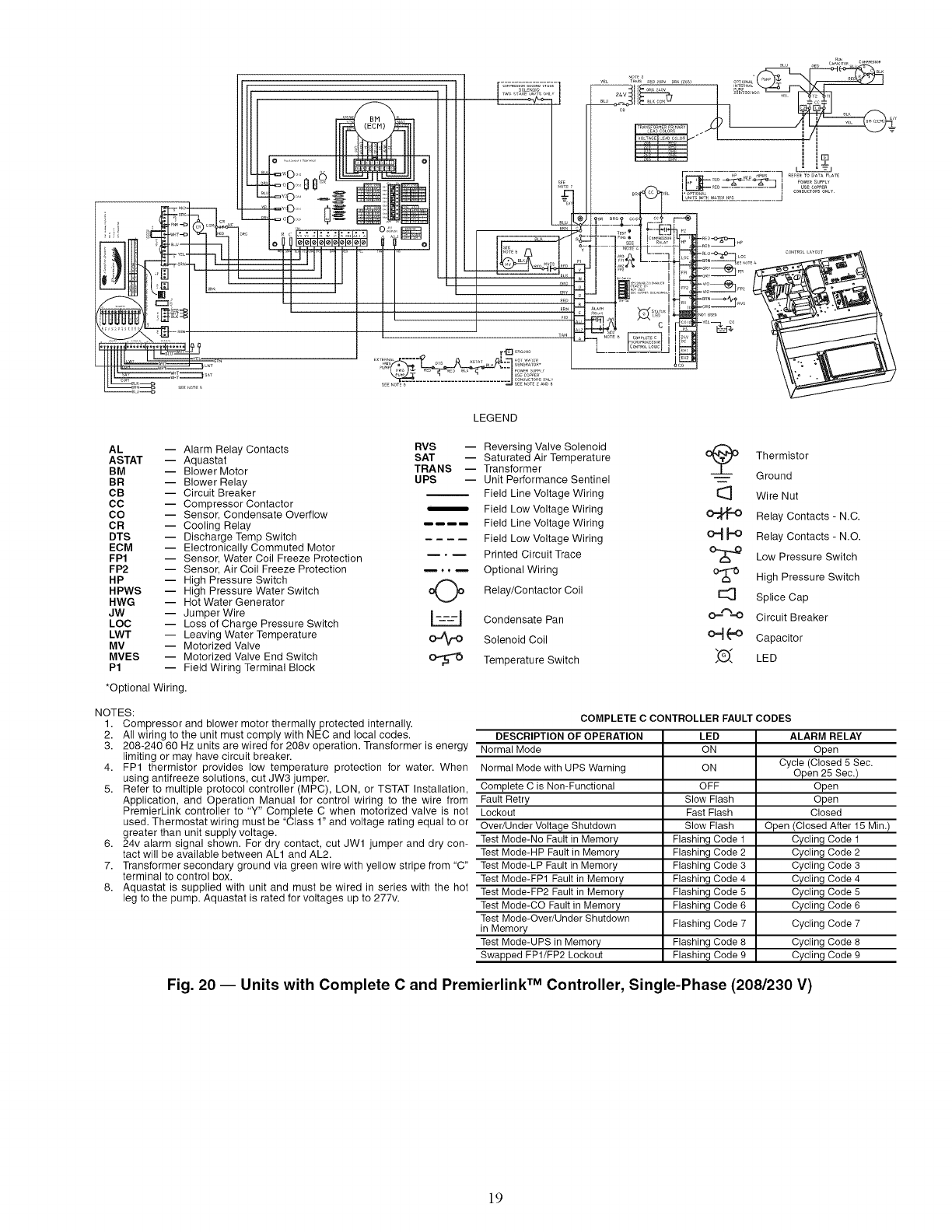
AL -- Alarm Relay Contacts RVS -- Reversing Valve Solenoid
ASTAT -- Aquastat SAT -- Saturated Air Temperature
BM -- Blower Motor TRANS -- Transformer
BR -- Blower Relay UPS -- Unit Performance Sentinel
CB -- Circuit Breaker Field Line Voltage Wiring
CO -- Compressor Contactor _, Field Low Voltage Wiring
CO -- Sensor, Condensate Overflow
OR -- Cooling Relay Field Line Voltage Wiring
DTS -- Discharge Temp Switch Field Low Voltage Wiring
ECM -- Electronically Commuted Motor
FP1 -- Sensor, Water Coil Freeze Protection Printed Circuit Trace
FP2 -- Sensor, Air Coil Freeze Protection .... Optional Wiring
HP -- High Pressure Switch
HPWS -- High Pressure Water Switch _ Relay/Contactor Coil
HWG -- Hot Water Generator
JW -- Jumper Wire I---I Condensate Pan
LOC -- Loss of Charge Pressure Switch L=7=7.J
LWT -- Leaving Water Temperature _ Solenoid Coil
MV -- Motorized Valve
MVES -- Motorized Valve End Switch _ Temperature Switch
P1 -- Field Wiring Terminal Block
*Optional Wiring.
NOTES:
1. Compressor and blower motor thermally protected internally.
2. All wiring to the unit must comply with NEC and local codes.
3. 208-240 60 Hz units are wired for 208v operation. Transformer is energy
limiting or may have circuit breaker.
4. FP1 thermistor provides low temperature protection for water. When
using antifreeze solutions, cut JW3 jumper.
5. Refer to multiple protocol controller (MPC), LON, or TSTAT Installation,
Application, and Operation Manual for control wiring to the wire from
PremierLink controller to "Y" Complete C when motorized valve is not
used. Thermostat wiring must be "Class 1" and voltage rating equal to or
greater than unit supply voltage.
6. 24v alarm signal shown. For dry contact, cut JW1 jumper and dry con-
tact will be available between ALl and AL2.
7. Transformer secondary ground via green wire with yellow stripe from "C"
terminal to control box.
8. Aquastat is supplied with unit and must be wired in series with the hot
leg to the pump. Aquastat is rated for voltages up to 277v.
O_ Thermistor
i Ground
[_ Wire Nut
Relay Contacts - N.C.
O._ _O Relay Contacts - N.O.
Low Pressure Switch
°_ High Pressure Switch
E_ Splice Cap
O_"%'O Circuit Breaker
O_ (-,O Capacitor
_(_)_ LED
COMPLETE C CONTROLLER FAULT CODES
DESCRIPTION OF OPERATION LED ALARM RELAY
Normal Mode ON Open
Cycle (Closed 5 Sec.
Normal Mode with UPS Warning ON Open 25 Sec.)
Complete C is Non-Functional OFF Open
Fault Retry Slow Flash Open
Lockout Fast Flash Closed
Over/Under Voltage Shutdown Slow Flash Open (Closed After 15 Min.)
Test Mode-No Fault in Memory Flashing Code 1 Cycling Code 1
Test Mode-HP Fault in Memory Flashing Code 2 Cycling Code 2
Test Mode-LP Fault in Memory Flashing Code 3 Cycling Code 3
Test Mode-FP1 Fault in Memory Flashing Code 4 Cycling Code 4
Test Mode-FP2 Fault in Memory Flashing Code 5 Cycling Code 5
Test Mode-CO Fault in Memory Flashing Code 6 Cycling Code 6
Test Mode-Over/Under Shutdown
in Memory Flashing Code 7 Cycling Code 7
Test Mode-UPS in Memory Flashing Code 8 Cycling Code 8
Swapped FP1/FP2 Lockout Flashing Code 9 Cycling Code 9
Fig. 20 -- Units with Complete C and Premierlink TM Controller, Single-Phase (208/230 V)
19
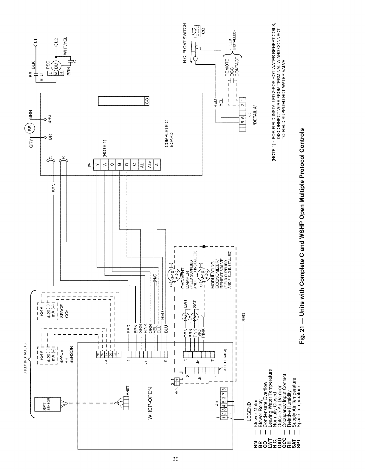
"7 _ d
ml o- t.m) z
__-
z
t,t,
if:
o
oIz:
M
W
t-
o
z
I I
O
w
b-
w
-Jr7
no::
O0
Om
i
oh_,'o
woo
_z_
frO0
4b
I I
I I
I I
S
w
I
z
cc
rn
Ir_
rLI-L
j____ j09(D
I
I I r
I I I
rLll
I > %'7"1 o
+4_i_<zw
lj j j a ogrro9
_=
l__ m
I
I I I i i rr _
,,,,,, 1 ½LI
',',I',',:LEELE
B Z
z
cc w
42 o
=d
T
j I w _
>_wz_7co Iz
_I o<-Z +_ wa
I
I
I 1_ rr7 "J7
0mm>E
,I111_
ul
LLLLLLL]
G
_b
ow
wo
3:::o
rrw
69
_wm
ZC3
W :::_ j
W
,roo m
g---o
w
i.-
©
z
o
•t-
_rr 0__ _<: _- _.<:L¢
o O O r'- _"o o.._.--_o
OO ooo_o• ___
mm©_jZ oOr'r CO_
IIIIIIIIII
_n..O _,_ 0 0 I.-I-
o
e..
0
0
0
o
0
o
O.
.i
o
O.
0
-r
00
-0
0_
0
o
o
O.
E
0
0
e-
l
.i
12.
2O
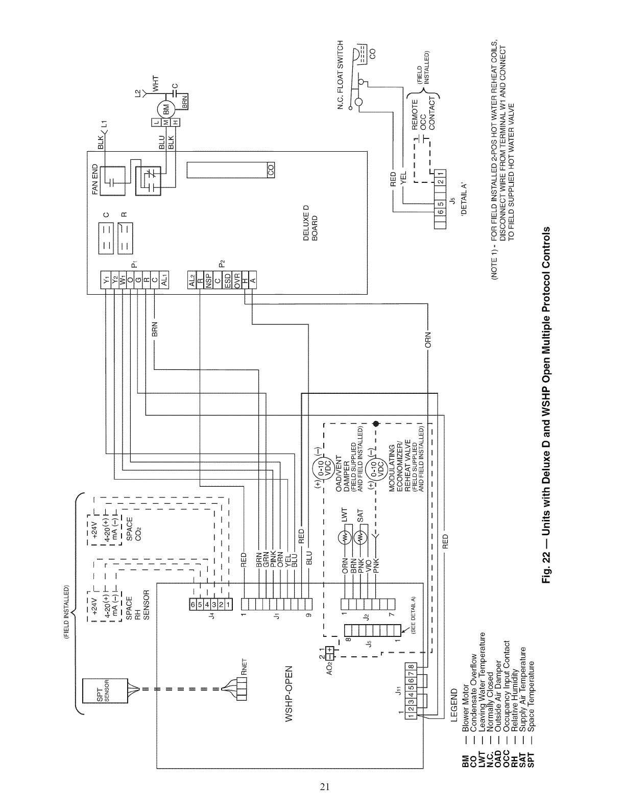
_<
8
gu
l
::E
rn
PI
(-3 IT"
t:! iio(o _
I
r L-L J, I
I F
III
rL.LI
I>
I+ q. EI w
!111!1
IIIIIIIII
_0_, "_o _
_O_ZO0_
21
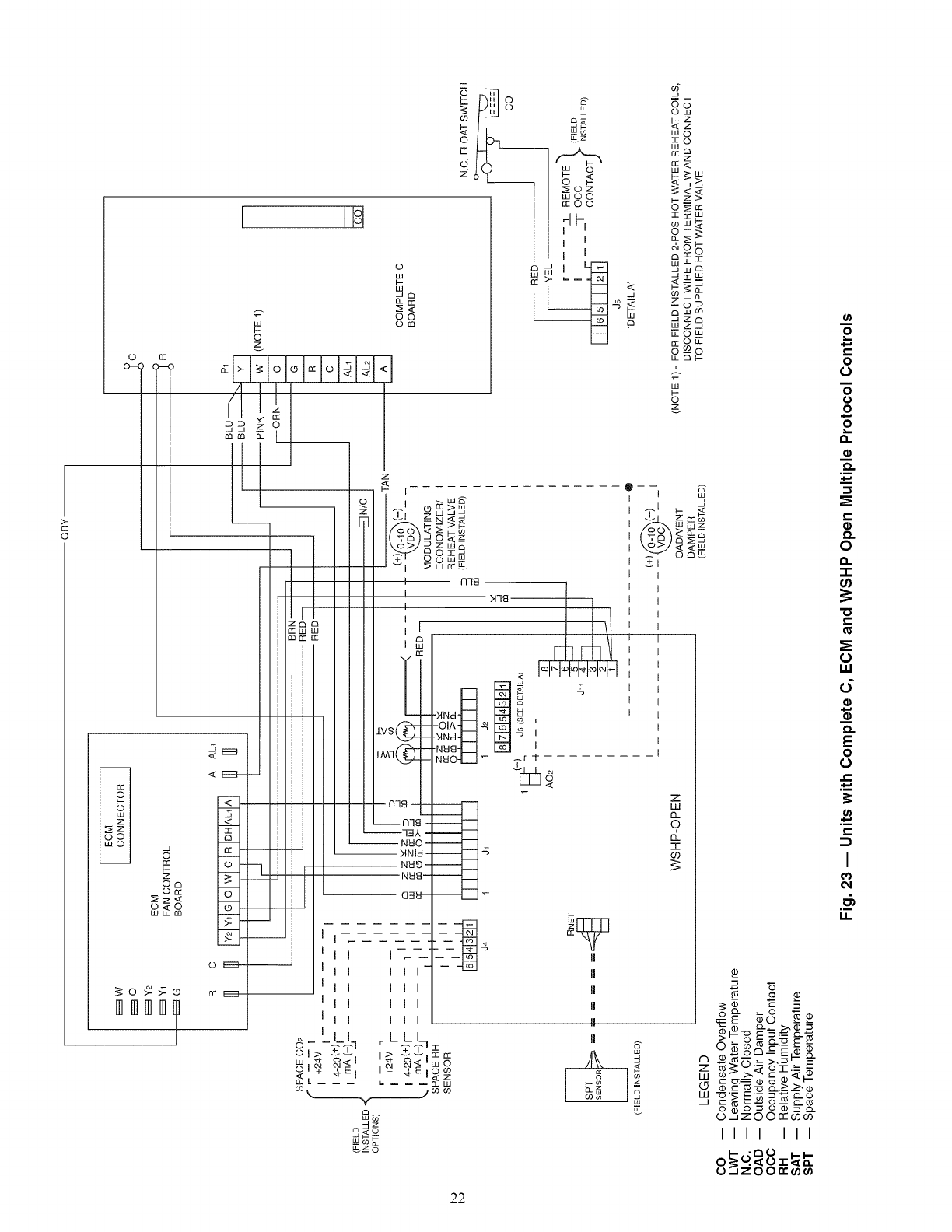
o
0--(i (
Z
S_
w m
I IIq
X2
_o
9
k_
W
k-
o
z
<E3--
Z -
.5
O
-6--
W
o _
mmmm
©
w
,_,<
oo
om
:1
m m
z
I_--W_
Ir_n- >w
I_w-Jq
k- -- >1-
I "7.r"aI-J 0 _ z
_Zw_
Wn 0n-_j
4-, O(DW_m
I nTg
I M78
I
MN
-XNd co
,XNd____I -S I
.NN_ll_ I
N_I04__I _ _f 7-
<
N78 -
__ n7 I
--7_A -
NWO-
MNId -
N_ID -
N_18--
(]3£1--
I I I
I I I
I I I
I I I
_LLI
*'_n 58
L _ _ _ W
/mr_
__.co t-
÷_z_
__z
n-O0
[I 17
I I
I I
_g
w
P
I
I
I
4 _
I
I
II
II
II
II
II
II
J
9
G
O©
ow
wo
IO
_9
z
o_
Im
©_
ao S
C3rr
WU- _
_©__
Z.
w
©
z
J
Wwz
>a.-
_c3
",X.5.,< <__
0_
+1
z
w
13..
9
T
22
_ O.- o-r._ _
¢ _ _--_ _.>.___¢
000 =o0 =_...
O..d Z 0 0 rr O0(,0
IIIIIIII
oo__O.',",o _-_-
00_
£
E
0
o
o
0
o
o
0
0
W
d
o
E
0
o
I
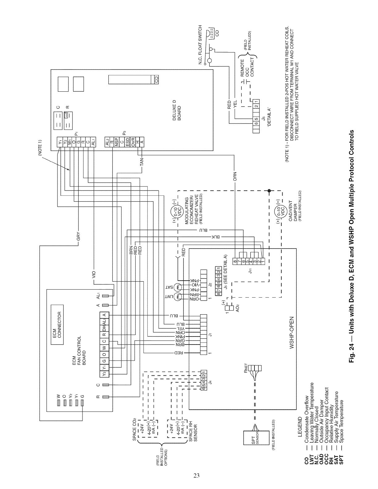
I !!o!
0 n,"
a
_r'_
wO
o_
:E
Ii
o h:-]:o
m0")
o _-_
frO0
d _
I I
I I
w
P
oz
wA
_z
rr'_
w_,,,
_>,
o_
rrW
&co©
_uz
_.J W 1_
-_ cc m_.
m i__a.
_zOD
mr/?
Szo
kuz_l
NON
otc
co o
?
o
W____
r---] <E_-
82 Io-7
,o_o
o
_o_>:® _:E_
mml]]m
Z
i
I
I
I
_ I_1_1
_L +4_EI
iii
i-
o
z
o
o___
_ 9
+1 n-_
I
I
I
M78
'I_I_I_I_I_I"I_I
'NNd
-O_A.l___I_ _ I
MNd-_ -_ I
NUa-b.--I
NUO _._1 _ r I--
E
III
III
III
III
r I- I-I.7
I> vv I
_ o_ _)
I + 4. E iOw_"
II
II
II
II
II
c_O
JF---
LU I--
--COO_
z
w
I3..
9
I:1.
7-
03
UOo3 _'--00
'_._ E_ =_-o ¢
o ¢,zOOn'_0_0
IIIIIIII
zO0_
E
e=
o
0
"6
o
o
E
o
o.
e=
o
o.
0
-r
=o
e=
0
iii
d
o
x
e.-
I
23
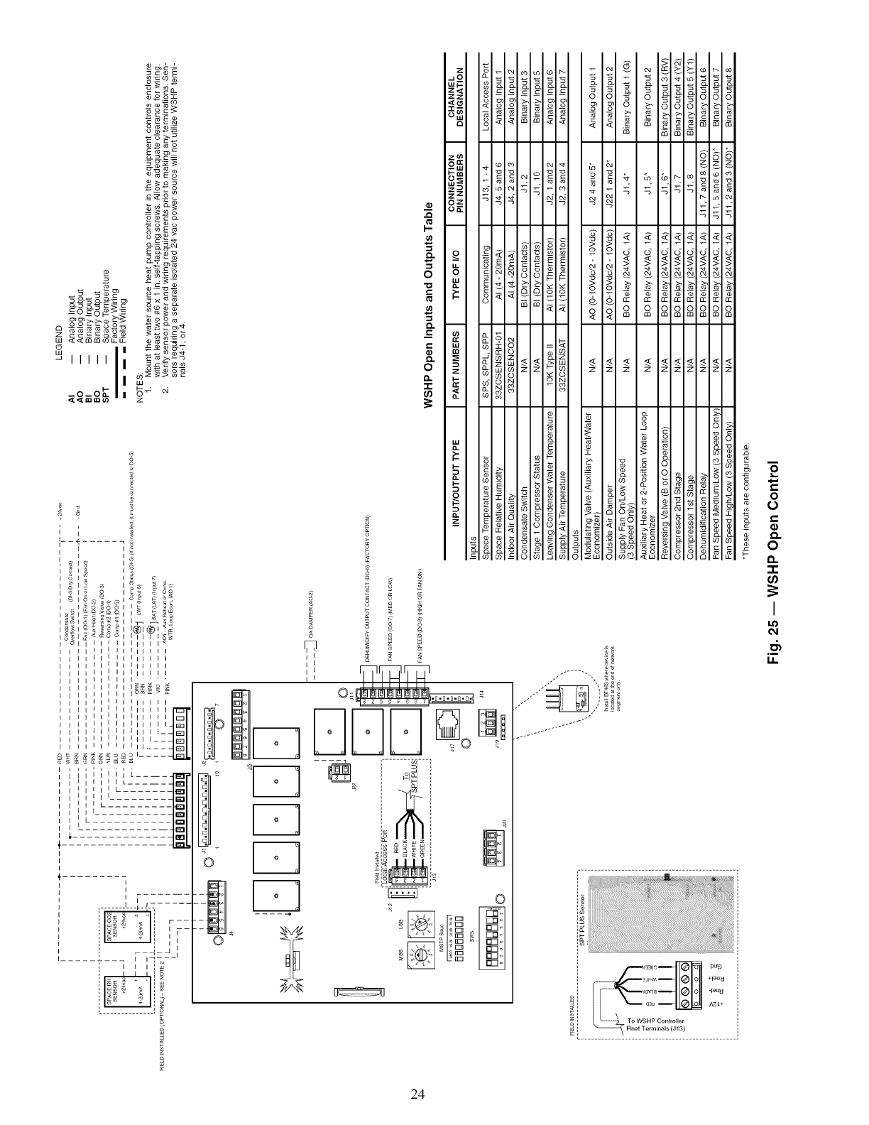
I
I
&
I I
i I I I
IiII I _ I
IiII I _ I
ii I I I
III I __
II 1
'12_-
e
i I I I L .... _
I I .....
I I I I [
I I I I
I I I
I I I
I I I
I I I
, ,_L
1 I
! IF-
I _ I ]
I--
o
€-
€-
o
8
£
s 8
_<
s 8 8
s s {
8 _ ° 8
i
UUU
0
@
3_H,S +leu _J
, _ovqa -leuu
oau AS[+
i To WSHP Controller
6
# £
5
0
=_ 0
"1-
I
I.I.
24
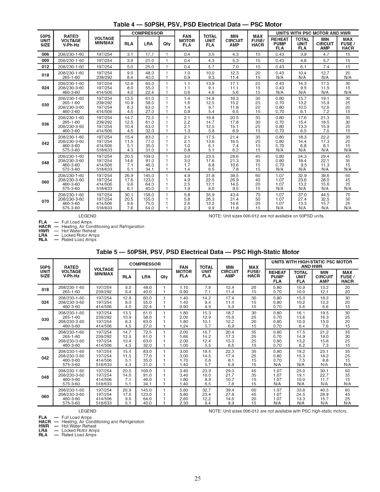
50PS
UNIT
SIZE
006
009
012
018
024
030
036
042
048
060
070
RATED
VOLTAGE
V-Ph-Hz
208/230-1-60
208/230-1-60
208/230-1-60
208/230-1-60
265-1-60
208/230-1-60
208/230-3-60
460-3-60
208/230-1-60
265-1-60
208/230-3-60
460-3-60
208/230-1-60
265-1-60
208/230-3-60
460-3-60
208/230-1-60
208/230-3-60
460-3-60
575-3-60
208/230-1-60
208/230-3-60
460-3-60
575-3-60
208/230-1-60
208/230-3-60
460-3-60
575-3-60
208/230-1-60
208/230-3-60
460-3-60
575-3-60
Table 4-- 50PSH, PSV, PSD Electrical Data -- PSC Motor
COMPRESSOR UNITS WITH PSC MOTOR AND HWR
VOLTAGE FAN TOTAL MIN MAX
MOTOR UNIT CIRCUIT FUSE/ REHEAT TOTAL MIN MAX
MIN/MAX RLA LRA Qty FLA FLA AMP HACR PUMP UNIT CIRCUIT FUSE /
FLA FLA AMP HACR
197/254 3.1 17.7 1 0.4 3.5 4.3 15 0.43 3.9 4.7 15
197/254 3.9 21.0 1 0.4 4.3 5.3 15 0.43 4.8 5.7 15
197/254 5.0 25.0 1 0.4 5.7 7.0 15 0.43 6.1 7.4 15
197/254 9.0 48.0 1 1.0 10.0 12.3 20 0.43 10.4 12.7 20
239/292 8.4 40.0 1 0.9 9.3 11.4 15 N/A N/A N/A N/A
197/254 12.8 60.0 1 1.1 13.9 17.1 25 0.43 14.3 17.5 30
197/254 8.0 55.0 1 1.1 9.1 11.1 15 0.43 9.5 11.5 15
414/506 4.0 22.4 1 0.6 4.6 5.6 15 N/A N/A N/A N/A
197/254 13.5 61.0 1 1.4 14.9 18.3 30 0.80 15.7 19.1 30
239/292 10.9 58.0 1 1.6 12.5 15.2 25 0.70 13.2 15.9 25
197/254 8.3 63.0 1 1.4 9.7 11.8 20 0.80 10.5 12.6 20
414/506 4.5 27.0 1 0.9 5.4 6.5 15 0.70 6.1 7.2 15
197/254 14.7 72.5 1 2.1 16.8 20.5 35 0.80 17.6 21.3 35
239/292 12.5 61.0 1 2.2 14.7 17.8 30 0.70 15.4 18.5 30
197/254 10.4 63.0 1 2.1 12.5 15.1 25 0.80 13.3 15.9 25
414/506 4.5 32.0 1 1.3 5.8 6.9 15 0.70 6.5 7.6 15
197/254 15.4 83.0 1 2.1 17.5 21.4 35 0.80 18.3 22.2 35
197/254 11.5 77.0 1 2.1 13.6 16.5 25 0.80 14.4 17.3 25
414/506 5.1 35.0 1 1.0 6.1 7.4 15 0.70 6.8 8.1 15
518/633 4.3 31.0 1 0.8 5.1 6.2 15 N/A N/A N/A N/A
197/254 20.5 109.0 1 3.0 23.5 28.6 45 0.80 24.3 29.4 45
197/254 14.6 91.0 1 3.0 17.6 21.3 35 0.80 18.4 22.1 35
414/506 7.1 46.0 1 1.7 8.8 10.6 15 0.70 9.5 11.3 15
518/633 5.1 34.1 1 1.4 6.5 7.8 15 N/A N/A N/A N/A
197/254 26.9 145.0 1 4.9 31.8 38.5 60 1.07 32.9 39.6 60
197/254 17.6 123.0 1 4.9 22.5 26.9 40 1.07 23.6 28.0 45
414/506 9.6 64.0 1 2.5 12.1 14.5 20 1.07 13.2 15.6 25
518/633 6.1 40.0 1 1.9 8.0 9.5 15 N/A N/A N/A N/A
197/254 30.1 158.0 1 5.8 35.9 43.4 70 1.07 37.0 44.5 70
197/254 20.5 155.0 1 5.8 26.3 31.4 50 1.07 27.4 32.5 50
414/506 9.6 75.0 1 2.6 12.2 14.6 20 1.07 13.3 15.7 25
518/633 7.6 54.0 1 2.3 9.9 11.8 15 N/A N/A N/A N/A
LEGEND
FLA -- Full Load Amps
HACR -- Heating, Air Conditioning and Refrigeration
HWR -- Hot Water Reheat
LRA -- Locked Rotor Amps
RLA -- Rated Load Amps
NOTE: Unit sizes 006-012 are not available on 50PSD units.
Table 5-- 50PSH, PSV, PSD Electrical Data -- PSC High-Static Motor
50PS
UNIT
SIZE
018
024
030
036
042
048
060
RATED
VOLTAGE
V-Ph-Hz
208/230-1-60
265-1-60
208/230-1-60
208/230-3-60
460-3-60
208/230-1-60
265-1-60
208/230-3-60
460-3-60
208/230-1-60
265-1-60
208/230-3-60
460-3-60
208/230-1-60
208/230-3-60
460-3-60
575-3-60
208/230-1-60
208/230-3-60
460-3-60
575-3-60
208/230-1-60
208/230-3-60
460-3-60
575-3-60
UNITS WITH HIGH-STATIC PSC MOTOR
COMPRESSOR
VOLTAGE FAN TOTAL MIN MAX AND HWR
MOTOR UNIT CIRCUIT FUSE/ REHEAT TOTAL MIN MAX
MIN/MAX RLA LRA Qty FLA FLA AMP HACR PUMP UNIT CIRCUIT FUSE /
FLA FLA AMP HACR
197/254 9.0 48.0 1 1.10 7.9 12.4 20 0.80 10.9 13.2 20
239/292 8.4 40.0 1 0.90 7.1 11.4 15 0.70 10.0 12.1 20
197/254 12.8 60.0 1 1.40 14.2 17.4 30 0.80 15.0 18.2 30
197/254 8.0 55.0 1 1.40 9.4 11.4 15 0.80 10.2 12.2 20
414/506 4.0 22.4 1 0.90 4.9 5.9 15 0.70 5.6 6.6 15
197/254 13.5 61.0 1 1.80 15.3 18.7 30 0.80 16.1 19.5 30
239/292 10.9 58.0 1 2.00 12.9 15.6 25 0.70 13.6 16.3 25
197/254 8.3 63.0 1 1.80 10.1 12.2 20 0.80 10.9 13.0 20
414/506 4.5 27.0 1 1.24 5.7 6.9 15 0.70 6.4 7.6 15
197/254 14.7 72.5 1 2.00 16.7 20.4 35 0.80 17.5 21.2 35
239/292 12.5 61.0 1 1.66 14.2 17.3 25 0.70 14.9 18.0 30
197/254 10.4 63.0 1 2.00 12.4 15.0 25 0.80 13.2 15.8 25
414/506 4.5 32.0 1 1.00 5.5 6.6 15 0.70 6.2 7.3 15
197/254 15.4 83.0 1 3.00 18.4 22.3 35 0.80 19.2 23.1 35
197/254 11.5 77.0 1 3.00 14.5 17.4 25 0.80 15.3 18.2 25
414/506 5.1 35.0 1 1.70 6.8 8.1 15 0.70 7.5 8.8 15
518/633 4.3 31.0 1 1.40 5.7 6.8 15 N/A N/A N/A N/A
197/254 20.5 109.0 1 3.40 23.9 29.0 45 1.07 25.0 30.1 50
197/254 14.6 91.0 1 3.40 18.0 21.7 35 1.07 19.1 22.7 35
414/506 7.1 46.0 1 1.80 8.9 10.7 15 1.07 10.0 11.7 15
518/633 5.1 34.1 1 1.40 6.5 7.8 15 N/A N/A N/A N/A
197/254 26.9 145.0 1 5.80 32.7 39.4 60 1.07 33.8 40.5 60
197/254 17.6 123.0 1 5.80 23.4 27.8 45 1.07 24.5 28.9 45
414/506 9.6 64.0 1 2.60 12.2 14.6 20 1.07 13.3 15.7 25
518/633 6.1 40.0 1 2.30 8.4 9.9 15 N/A N/A N/A N/A
LEGEND
FLA -- Full Load Amps
HACR -- Heating, Air Conditioning and Refrigeration
HWR -- Hot Water Reheat
LRA -- Locked Rotor Amps
RLA -- Rated Load Amps
NOTE: Unit sizes 006-012 are not available with PSC high-static motors.
25
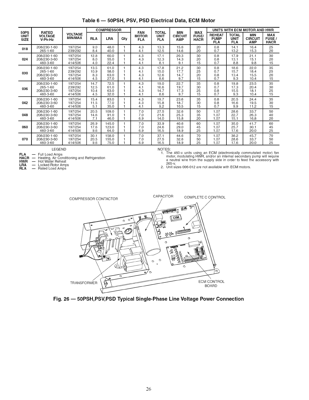
Table 6 -- 50PSH, PSV, PSD Electrical Data, ECM Motor
50PS
UNIT
SIZE
018
O24
030
036
O42
048
060
070
RATED
VOLTAGE
V-Ph-Hz
208/230-1-60
265-1-60
208/230-1-60
208/230-3-60
460-3-60
208/230-1-60
265-1-60
208/230-3-60
460-3-60
208/230-1-60
265-1-60
208/230-3-60
460-3-60
208/230-1-60
208/230-3-60
460-3-60
208/230-1-60
208/230-3-60
460-3-60
208/230-1-60
208/230-3-60
460-3-60
208/230-1-60
208/230-3-60
460-3-60
VOLTAGE
MINIMAX
COMPRESSOR FAN TOTAL MIN MAX
MOTOR UNIT CIRCUIT FUSE/
RLA LRA Qty FLA FLA AMP HACR
197/254 9.0 48.0 1 4.3 13.3 15.6 20
239/292 8.4 40.0 1 4.1 12.5 14.6 20
197/254 12.8 60.0 1 4.3 17.1 20.3 30
197/254 8.0 55.0 1 4.3 12.3 14.3 20
414/506 4.0 22.4 1 4.1 8.1 9.1 15
197/254 13.5 61.0 1 4.3 17.8 21.2 30
239/292 10.9 58.0 1 4.1 15.0 17.7 25
197/254 8.3 63.0 1 4.3 12.6 14.7 20
414/506 4.5 27.0 1 4.1 8.6 9.7 15
197/254 14.7 72.5 1 4.3 19.0 22.7 35
239/292 12.5 61.0 1 4.1 16.6 19.7 30
197/254 10.4 63.0 1 4.3 14.7 17.3 25
414/506 4.5 32.0 1 4.1 8.6 9.7 15
197/254 15.4 83.0 1 4.3 19.7 23.6 35
197/254 11.5 77.0 1 4.3 15.8 18.7 30
414/506 5.1 35.0 1 4.1 9.2 10.5 15
197/254 20.5 109.0 1 7.0 27.5 32.6 50
197/254 14.6 91.0 1 7.0 21.6 25.3 35
414/506 7.1 46.0 1 6.9 14.0 15.8 20
197/254 26.9 145.0 1 7.0 33.9 40.6 60
197/254 17.6 123.0 1 7.0 24.6 29.0 45
414/506 9.6 64.0 1 6.9 16.5 18.9 25
197/254 30.1 158.0 1 7.0 37.1 44.6 70
197/254 20.5 155.0 1 7.0 27.5 32.6 50
414/506 9.6 75.0 1 6.9 16.5 18.9 25
LEGEND
FLA -- Full Load Amps
HACR -- Heating, Air Conditioning and Refrigeration
HWR -- Hot Water Reheat
LRA -- Locked Rotor Amps
RLA -- Rated Load Amps
UNITS WITH ECM MOTOR AND HWR
REHEAT TOTAL MIN MAX
PUMP UNIT CIRCUIT FUSE /
FLA FLA AMP HACR
0.8 14.1 16.4 25
0.7 13.2 15.3 20
0.8 17.9 21.1 30
0.8 13.1 15.1 20
0.7 8.8 9.8 15
0.8 18.6 22.0 35
0.7 15.7 18.4 25
0.8 13.4 15.5 20
0.7 9.3 10.4 15
0.8 19.8 23.5 35
0.7 17.3 20.4 30
0.8 15.5 18.1 25
0.7 9.3 10.4 15
0.8 20.5 24.4 35
0.8 16.6 19.5 30
0.7 9.9 11.2 15
1.07 28.6 33.7 50
1.07 22.7 26.3 40
1.07 15.1 16.8 20
1.07 35.0 41.7 60
1.07 25.7 30.1 45
1.07 17.6 20.0 25
1.07 38.2 45.7 70
1.07 28.6 33.7 50
1.07 17.6 20.0 25
NOTES:
1. The 460-v units using an ECM (electronically commutated motor) fan
motor, modulating HWR, and/or an internal secondary pump will require
a neutral wire from the supply side in order to feed the accessory with
265-v.
2. Unit sizes 006-012 are not available with ECM motors.
COMPRESSOR CONTACTOR
\CAPACITOR COMPLETE C CONTROL
TRANSFORMER ECM CONTROL
BOARD
Fig. 26 -- 50PSH,PSV, PSD Typical Single-Phase Line Voltage Power Connection
26
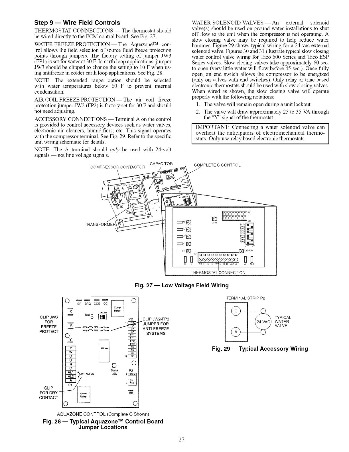
Step 9 -- Wire Field Controls
THERMOSTAT CONNECTIONS -- The thermostat should
be wired directly to the ECM control board. See Fig. 27.
WATER FREEZE PROTECTION-- The Aquazone TM con-
trol allows the field selection of source fluid freeze protection
points through jumpers. The factory setting of jumper JW3
(FP1) is set for water at 30 E In earth loop applications, jumper
JW3 should be clipped to change the setting to 10 F when us-
ing antifreeze in colder earth loop applications. See Fig. 28.
NOTE: The extended range option should be selected
with water temperatures below 60 F to prevent internal
condensation.
AIR COIL FREEZE PROTECTION-- The air coil freeze
protection jumper JW2 (FP2) is factory set for 30 F and should
not need adjusting.
ACCESSORY CONNECTIONS -- Terminal A on the control
is provided to control accessory devices such as water valves,
electronic air cleaners, humidifiers, etc. This signal operates
with the compressor terminal. See Fig. 29. Refer to the specific
unit wiring schematic for details.
NOTE: The A terminal should only be used with 24-volt
signals -- not line voltage signals.
CAPACITOR
COMPRESSOR CONTACTOR
WATER SOLENOID VALVES -- An external solenoid
valve(s) should be used on ground water installations to shut
off flow to the unit when the compressor is not operating. A
slow closing valve may be required to help reduce water
halrnner. Figure 29 shows typical wiring for a 24-vac external
solenoid valve. Figures 30 and 31 illustrate typical slow closing
water control valve wiring for Taco 500 Series and Taco ESP
Series valves. Slow closing valves take approximately 60 sec.
to open (very little water will flow before 45 sec.). Once fully
open, an end switch allows the compressor to be energized
(only on valves with end switches). Only relay or triac based
electronic thermostats should be used with slow closing valves.
When wired as shown, the slow closing valve will operate
properly with the following notations:
1. The valve will remain open during a unit lockout.
2. The valve will draw approximately 25 to 35 VA through
the "Y" signal of the thermostat.
IMPORTANT: Connecting a water solenoid valve can ]
overheat the anticipators of electromechanical thermo- I
stats. Only use relay based electronic thermostats.
COMPLETE C CONTROL
TRANSFORMER
R_ 0 TBI _A_ A_LI0000000000
THERMOSTAT CONNECTION
Fig. 27 -- Low Voltage Field Wiring
CLIPJW3
FOR
FREEZE .....
PROTECT
CLIP
FOR DRY -
CONTACT
OeR BRe CCG cc [------] O
"=_ _o_
= ,o,,o[] P2
J_ IF_ F_ Low Te_ LP
Oy FP
o
CLIP JW2-FP2
I JUMPER FOR
ANTI-FREEZE
SYSTEMS
AQUAZONE CONTROL (Complete C Shown)
Fig. 28 -- Typical Aquazone TM Control Board
Jumper Locations
TERMINAL STRIP P2
TYPICAL
WATER
VALVE
Fig. 29 -- Typical Accessory Wiring
27
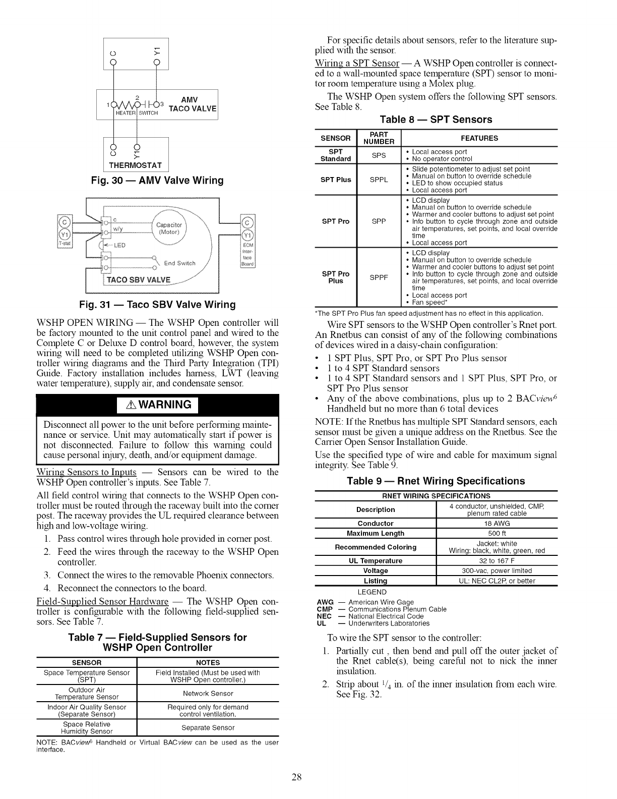
o _-
1 !3TAo LvE
.E° sTAT
Fig. 30 -- AMV Valve Wiring
Fig. 31 -- Taco SBV Valve Wiring
WSHP OPEN WIRING -- The WSHP Open controller will
be factory mounted to the unit control panel and wired to the
Complete C or Deluxe D control board, however, the system
wiring will need to be completed utilizing WSHP Open con-
troller wiring diagrams and the Third Party Integration (TPI)
Guide. Factory installation includes harness, LWT (leaving
water temperature), supply air, and condensate sensor.
Disconnect all power to the unit before performing mainte-
nance or service. Unit may automatically start if power is
not disconnected. Failure to follow this warning could
cause personal injury, death, and/or equipment damage.
Wiring Sensors to Inputs -- Sensors can be wired to the
WSHP Open controller's inputs. See Table 7.
All field control wiring that connects to the WSHP Open con-
troller must be routed through the raceway built into the corner
post. The raceway provides the UL required clearance between
high and low-voltage wiring.
1. Pass control wires through hole provided in corner post.
2. Feed the wires through the raceway to the WSHP Open
controller.
3.
4.
Connect the wires to the removable Phoenix connectors.
Reconnect the connectors to the board.
Field-Supplied Sensor Hardware -- The WSHP Open con-
troller is configurable with the following field-supplied sen-
sors. See Table 7.
Table 7 -- Field-Supplied Sensors for
WSHP Open Controller
SENSOR NOTES
Space Temperature Sensor Field Installed (Must be used with
(SPT) WSHP Open controller.)
Outdoor Air
Temperature Sensor Network Sensor
Indoor Air Quality Sensor Required only for demand
(Separate Sensor) control ventilation.
Space Relative Separate Sensor
Humidity Sensor
NOTE: BACview s Handheld or Virtual BACview can be used as the user
interface.
For specific details about sensors, refer to the literature sup-
plied with the sensor.
Wiring a SPT Sensor -- A WSHP Open controller is connect-
ed to a wall-mounted space temperature (SPT) sensor to moni-
tor room temperature using a Molex plug.
The WSHP Open system offers the following SPT sensors.
See Table 8.
Table 8 -- SPT Sensors
PART
SENSOR NUMBER FEATURES
SPT
Standard • Local access port
SPS • No operator control
• Slide potentiometer to adjust set point
• Manual on button to override schedule
SPT Plus SPPL • LED to show occupied status
• Local access port
• LCD display
• Manual on button to override schedule
• Warmer and cooler buttons to adjust set point
SPT Pro SPP • Info button to cycle through zone and outside
air temperatures, set points, and local override
time
• Local access port
• LCD display
• Manual on button to override schedule
• Warmer and cooler buttons to adjust set point
SPT Pro • Info button to cycle through zone and outside
Plus SPPF air temperatures, set points, and local override
time
• Local access port
• Fan speed*
*The SPT Pro Plus fan speed adjustment has no effect in this application.
Wire Sift sensors to the WSHP Open controller's Rnet port.
An Rnetbus can consist of any of the following combinations
of devices wired in a daisy-chain configuration:
• 1 SPT Plus, SPT Pro, or SPT Pro Plus sensor
• 1 to 4 SPT Standard sensors
• 1 to 4 SPT Standard sensors and 1 SPT Plus, SPT Pro, or
SPT Pro Plus sensor
• Any of the above combinations, plus up to 2 BACview 6
Handheld but no more than 6 total devices
NOTE: If the Rnetbus has multiple Sift Standard sensors, each
sensor must be given a unique address on the Rnetbus. See the
Carrier Open Sensor Installation Guide.
Use the specified type of wire and cable for lnaxhnum signal
integrity. See Table 9.
Table 9 -- Rnet Wiring Specifications
AWG
CMP
NEC
UL
RNET WIRING SPECIFICATIONS
Description 4 conductor, unshielded, CMP,
plenum rated cable
Conductor 18 AWG
Maximum Length 500 ft
Jacket: white
Recommended Coloring Wiring: black, white, green, red
UL Temperature 32 to 167 F
Voltage 300-vac, power limited
Listing UL: NEC CL2P, or better
LEGEND
-- American Wire Gage
-- Communications Plenum Cable
-- National Electrical Code
-- Underwriters Laboratories
To wire the SPT sensor to the controller:
1. Partially cut, then bend and pull off the outer .jacket of
the Rnet cable(s), being careful not to nick the inner
insulation.
2. Strip about l/4 in. of the inner insulation from each wire.
See Fig. 32.
28
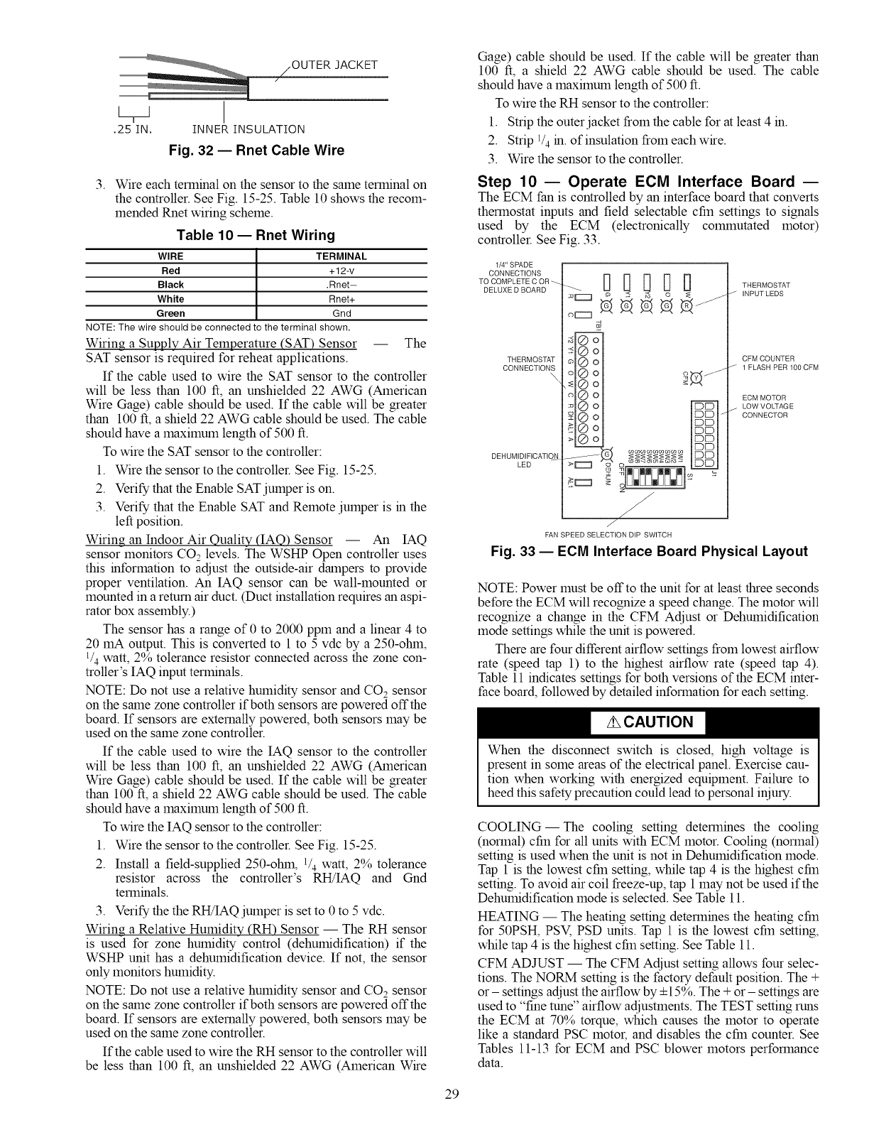
/OUTER JACKET
[TJ
.25IN. INNER INSULATION
Fig. 32 -- Rnet Cable Wire
3. Wire each terminal on the sensor to the same terminal on
the controller. See Fig. 15-25. Table 10 shows the recom-
mended Rnet wiring scheme.
Table 10 -- Rnet Wiring
WIRE TERMINAL
Red +12-v
Black .Rnet-
White Rnet+
Green Gnd
NOTE: The wire should be connected to the terminal shown.
Wiring a Supply Air Temperature (SAT) Sensor -- The
SAT sensor is required for reheat applications.
If the cable used to wire the SAT sensor to the controller
will be less than 100 ft, an unshielded 22 AWG (American
Wire Gage) cable should be used. If the cable will be greater
than 100 ft, a shield 22 AWG cable should be used. The cable
should have a maximum length of 500 ft.
To wire the SAT sensor to the controller:
1. Wire the sensor to the controller. See Fig. 15-25.
2. Verify that the Enable SATjumper is on.
3. Verify that the Enable SAT and Remote jumper is in the
left position.
Wiring an Indoor Air Quality (IAQ) Sensor -- An IAQ
sensor monitors CO2 levels. The WSHP Open controller uses
this information to adjust the outside-air dalnpers to provide
proper ventilation. An IAQ sensor can be wall-mounted or
mounted in a return air duct. (Duct installation requires an aspi-
rator box assembly.)
The sensor has a range of 0 to 2000 ppm and a linear 4 to
20 mA output. This is converted to 1 to 5 vdc by a 250-ohin,
1/4watt, 2% tolerance resistor connected across the zone con-
troller's IAQ input terminals.
NOTE: Do not use a relative humidity sensor and CO2sensor
on the sane zone controller if both sensors are powered off the
board. If sensors are externally powered, both sensors may be
used on the same zone controller.
If the cable used to wire the IAQ sensor to the controller
will be less than 100 ft, an unshielded 22 AWG (American
Wire Gage) cable should be used. If the cable will be greater
than 100 ft, a shield 22 AWG cable should be used. The cable
should have a maximum length of 500 ft.
To wire the IAQ sensor to the controller:
1. Wire the sensor to the controller. See Fig. 15-25.
2. Install a field-supplied 250-ohin, 1/4 watt, 2% tolerance
resistor across the controller's RH!IAQ and Gnd
terminals.
3. Verify the the RH!IAQ julnper is set to 0 to 5 vdc.
Wiring a Relative Humidity (RH) Sensor -- The RH sensor
is used for zone humidity control (dehumidification) if the
WSHP unit has a dehumidification device. If not, the sensor
only monitors humidity.
NOTE: Do not use a relative humidity sensor and CO 2sensor
on the sane zone controller if both sensors are powered off the
board. If sensors are externally powered, both sensors may be
used on the same zone controller.
If the cable used to wire the RH sensor to the controller will
be less than 100 ft, an unshielded 22 AWG (American Wire
Gage) cable should be used. If the cable will be greater than
100 ft, a shield 22 AWG cable should be used. The cable
should have a maximum length of 500 ft.
To wire the RH sensor to the controller:
1. Strip the outer jacket from the cable for at least 4 in.
2. Strip 1/4in. of insulation from eachwire.
3. Wire the sensor to the controller.
Step 10 -- Operate ECM Interface Board
The ECM fan is controlled by an interface board that converts
thermostat inputs and field selectable cfm settings to signals
used by the ECM (electronically COlrUnutated motor)
controller. See Fig. 33.
1/4" SPADE
CONNECTIONS
TO COMPLETE C OR
DELUXE D BOARD
THERMOSTAT
CONNECTIONS
\
DEHUMIDIFICATIO_
LED
£
-<
cocococococococo co
-W........ ===_=I=_=
!r--_ £
FAN SPEED SELECTION DIP SWITCH
THERMOSTAT
J INPUT LEDS
CFM COUNTER
J 1FLASH PERIOOCFM
ECM MOTOR
_- LOW VOYAGE
CONNECTOR
Fig. 33 -- ECM Interface Board Physical Layout
NOTE: Power must be offto the unit for at least three seconds
before the ECM will recognize a speed change. The motor will
recognize a change in the CFM Adjust or Dehumidification
mode settings while the unit is powered.
There are four different airflow settings from lowest airflow
rate (speed tap 1) to the highest airflow rate (speed tap 4).
Table 11 indicates settings for both versions of the ECM inter-
face board, followed by detailed information for each setting.
When the disconnect switch is closed, high voltage is
present in some areas of the electrical panel. Exercise cau-
tion when working with energized equipment. Failure to
heed this safety precaution could lead to personal iniury.
COOLING--The cooling setting determines the cooling
(normal) cfm for all units with ECM motor. Cooling (normal)
setting is used when the unit is not in Dehumidification mode.
Tap 1 is the lowest cfm setting, while tap 4 is the highest cfm
setting. To avoid air coil freeze-up, tap 1 may not be used if the
Dehumidification mode is selected. See Table 11.
HEATING -- The heating setting determines the heating cfm
for 50PSH, PSV, PSD units. Tap 1 is the lowest cfm setting,
while tap 4 is the highest cfm setting. See Table 11.
CFM ADJUST -- The CFM Adjust setting allows four selec-
tions. The NORM setting is the factory default position. The +
or- settings adjust the airflow by 4-15%. The + or- settings are
used to "fine rune" airflow adjustments. The TEST setting runs
the ECM at 70% torque, which causes the motor to operate
like a standard PSC motor, and disables the cfm counter. See
Tables 11-13 for ECM and PSC blower motors performance
data.
29
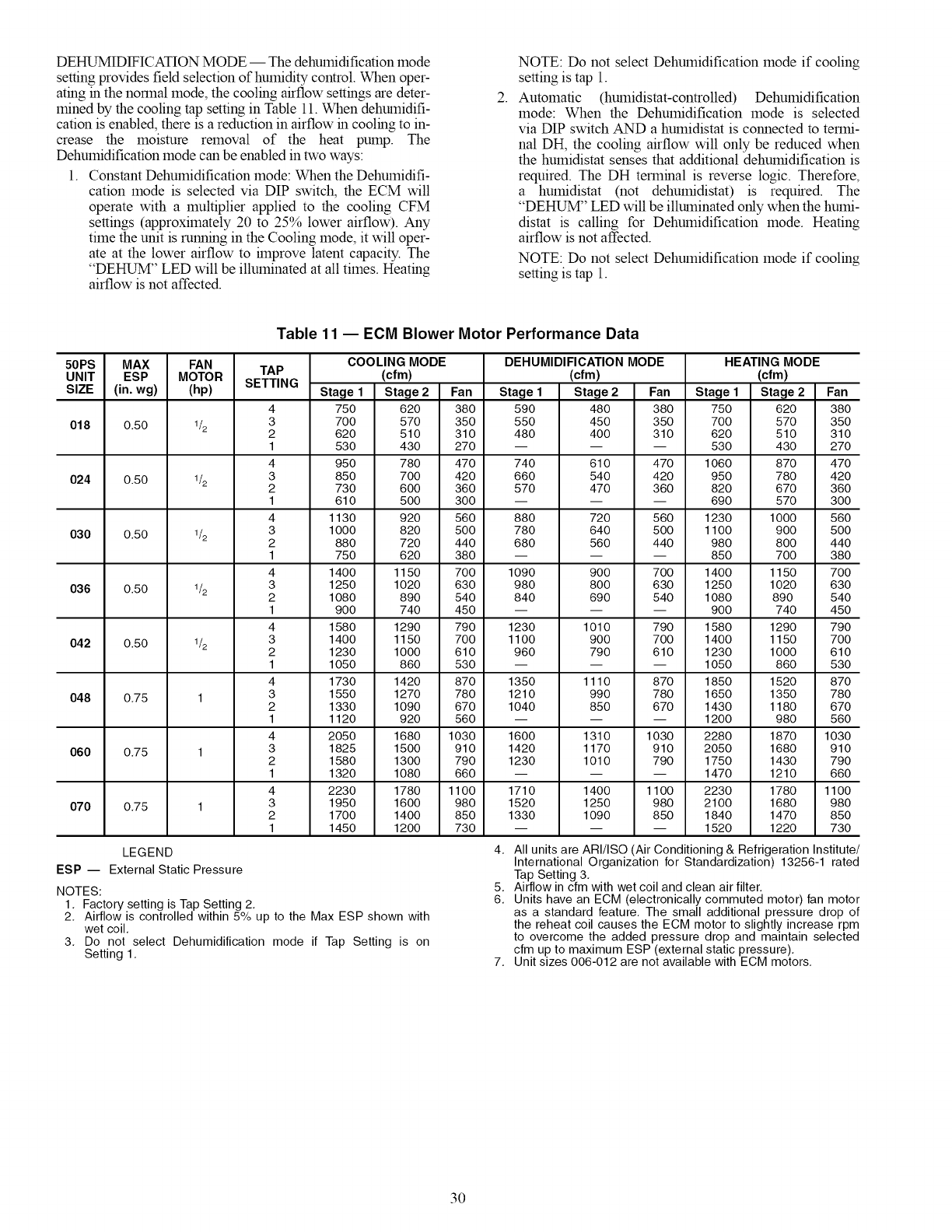
DEHUMIDIFICATIONMODE-- Thedehumidificationmode
settingprovidesfieldselectionofhumiditycontrol.Whenoper-
atinginthenormalmode,thecoolingairflowsettingsaredeter-
minedbythecoolingtapsettinginTable11.Whendehumidifi-
cationisenabled,thereisareductioninairflowincoolingtoin-
creasethe moistureremovalof the heatpump.The
Dehumidificationmodecanbeenabledintwoways:
1. ConstantDehumidificationmode:WhentheDehumidifi-
cationmodeisselectedviaDIPswitch,theECMwill
operatewitha multiplierappliedto thecoolingCFM
settings(approximately20to25%lowerairflow).Any
timetheunitisrunningintheCoolingmode,it willoper-
ateatthelowerairflowtohnprovelatentcapacity.The
"DEHUM"LEDwillbeilluminatedatalltimes.Heating
airflowisnotaffected.
2.
NOTE: Do not select Dehumidification mode if cooling
setting is tap 1.
Automatic (humidistat-controlled) Dehumidification
mode: When the Dehumidification mode is selected
via DIP switch AND a humidistat is connected to termi-
nal DH, the cooling airflow will only be reduced when
the humidistat senses that additional dehumidification is
required. The DH terminal is reverse logic. Therefore,
a humidistat (not dehumidistat) is required. The
"DEHUM" LED will be illuminated only when the humi-
distat is calling for Dehumidification mode. Heating
airflow is not affected.
NOTE: Do not select Dehumidification mode if cooling
setting is tap 1.
Table 11 -- ECM Blower Motor Performance Data
50PS MAX FAN
UNIT ESP MOTOR
SIZE (in. wg) (hp)
018 0.50 1/2
024 0.50 1/2
030 0.50 1/2
036 0.50 1/2
042 0.50 1/2
048 0.75
060 0.75
070 0.75
TAP
SETTING
4
3
2
1
4
3
2
1
4
3
2
1
4
3
2
1
4
3
2
1
4
3
2
1
4
3
2
1
4
3
2
1
COOLING MODE HEATING MODE
(cfm) (cfm)
Stage 2 Fan Stage 1 Stage 2 Fan
480 380 750 620 380
450 350 700 570 350
400 310 620 510 310
-- -- 530 430 270
610 470 1060 870 470
540 420 950 780 420
470 360 820 670 360
-- -- 690 570 300
720 560 1230 1000 560
640 500 1100 900 500
560 440 980 800 440
-- -- 850 700 380
900 700 1400 1150 700
800 630 1250 1020 630
690 540 1080 890 540
-- -- 900 740 450
1010 790 1580 1290 790
900 700 1400 1150 700
790 610 1230 1000 610
-- -- 1050 860 530
1110 870 1850 1520 870
990 780 1650 1350 780
850 670 1430 1180 670
-- -- 1200 980 560
1310 1030 2280 1870 1030
1170 910 2050 1680 910
1010 790 1750 1430 790
-- -- 1470 1210 660
1400 1100 2230 1780 1100
1250 980 2100 1680 980
1090 850 1840 1470 850
-- -- 1520 1220 730
DEHUMIDIFICATION MODE
(cfm)
Stage 1 Stage 2 Fan Stage 1
750 620 380 590
700 570 350 550
620 510 310 480
530 430 270 --
950 780 470 740
850 700 420 660
730 600 360 570
610 500 300 --
1130 920 560 880
1000 820 500 780
880 720 440 680
750 620 380 --
1400 1150 700 1090
1250 1020 630 980
1080 890 540 840
900 740 450 --
1580 1290 790 1230
1400 1150 700 1100
1230 1000 610 960
1050 860 530 --
1730 1420 870 1350
1550 1270 780 1210
1330 1090 670 1040
1120 920 560 --
2050 1680 1030 1600
1825 1500 910 1420
1580 1300 790 1230
1320 1080 660 --
2230 1780 1100 1710
1950 1600 980 1520
1700 1400 850 1330
1450 1200 730 --
LEGEND
ESP -- External Static Pressure
NOTES:
1. Factory setting is Tap Setting 2.
2. Airflow is controlled within 5% up to the Max ESP shown with
wet coil.
3. Do not select Dehumidification mode if Tap Setting is on
Setting 1.
4. All units are ARI/ISO (Air Conditioning & Refrigeration Institute/
International Organization for Standardization) 13256-1 rated
Tap Setting 3.
5. Airflow in cfm with wet coil and clean air filter.
6. Units have an ECM (electronically commuted motor) fan motor
as a standard feature. The small additional pressure drop of
the reheat coil causes the ECM motor to slightly increase rpm
to overcome the added pressure drop and maintain selected
cfm up to maximum ESP (external static pressure).
7. Unit sizes 006-012 are not available with ECM motors.
3O
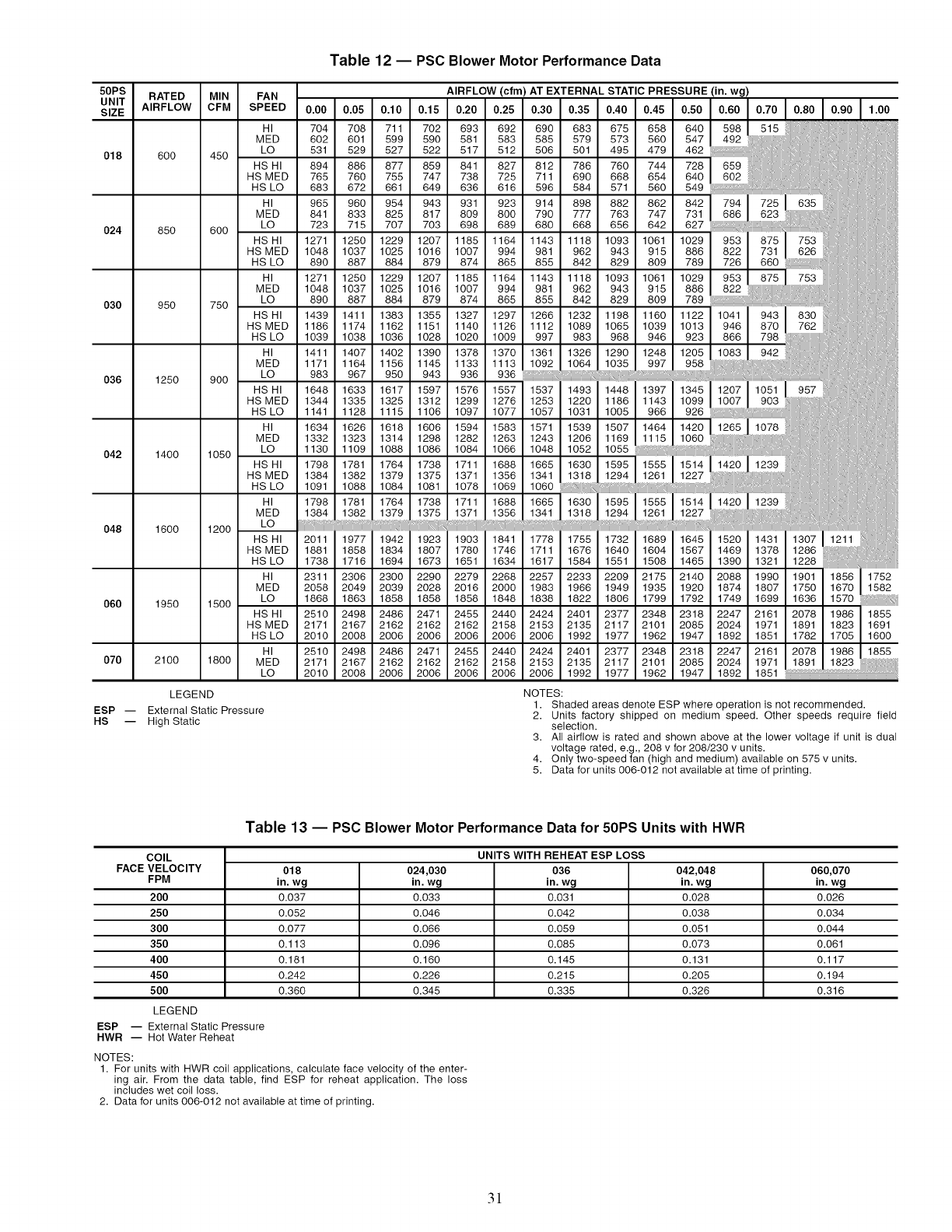
Table 12 -- PSC Blower Motor Performance Data
50PS
UNIT
SIZE
018
O24
030
036
O42
048
060
070
RATED MIN
AIRFLOW CFM
600
85O
950
1250
1400
1600
1950
2100
FAN AIRFLOW (cfm) AT EXTERNAL STATIC PRESSURE (in. wg)
SPEED 0.00 0.05 0.10 0.15 0.20 0.25 0.30 0.35 0.40 0.45 0.50 0.60 ).70 0.80 0.90 1.00
HI 704 708 711 702 693 692 690 683 675 658 640 598 515 ii
MED 602 601 599 590 581 583 585 579 573 560 547 492 :i i
450 LO 531 529 527 522 517 512 506 501 495 479 462
HSHI 894 886 877 859 841 827 812 786 760 744 728 I 659 ......
HS MED 765 760 755 747 738 725 711 690 668 654 640 602
HS LO 683 672 661 649 636 616 596 584 571 560 549 ',,,: iii:[i
HI 965 960 954 943 931 923 914 898 882 862 842 I 794 ] 7251 635 !: :
MED 841 833 825 817 809 800 790 777 763 747 731 686 623 iii,iii
I q
600 LO 723 715 707 703 698 689 680 668 656 642 627 i :: ,,_t i:ii:i
HSHI 1271 1250 1229 1207 1185 1164 1143 1118 1093 1061 lO291
HSMED 1048 1037 1025 1016 1007 994 981 962 943 915 886 I 822 I 731 626 i ,
HS LO 890 887 884 879 874 865 855 842 829 809 789 726 660 {
HI 1271 1250 1229 1207 1185 1164 1143 1118 1093 1061 1029 I 953 875 I 753 : '
MED 1048 1037 1025 1016 1007 994 981 962 943 915 886 822
750 LO 890 887 884 879 874 865 855 842 829 809 789 ii
HSHI 1439 1411 1383 1355 1327 1297 1266 1232 1198 1160 11221io4;i;&i ;3o
HSMED 1186 1174 1162 1151 1140 1126 1112 1089 1065 1039 1013 I 946 I 870 I 76211
HSLO 1039 1038 1036 1028 1020 1009 997 983 968 946 923I 866 I 798
HI 1411 1407 1402 1390 1378 1370 1361 1326 1290 1248 1205 1083 I 942:
MED 1171 1164 1156 1145 1133 1113 1092 1064 1035 997 958 i
900 LO 983 967 950 943 936 936
HSHI 1648 1633 1617 1597 1576 15571 15371 14931 1448 I 13971 13451 12071 1051 I 957• , • • , , , ,
HSMED 1344 1335 1325 1312 1299 1276 I1253 I12201 1186 I1143 I1099 1007 I903
HS LO 1141 1128 1115 1106 1097 1077 1057 1031 1005 I966 926 :i :i
HI 1634 1626 1618 1606 1594 1583 11571115391150711464114201265I lO78
NED 1332 1323 1314 1298 1282 1263 I1243 I12061 1169 I1115 lO6O i ;
1050 LO 1130 1109 1088 1086 1084 1066 1048 1052 1055 ;i:: [
HSHI 1798 1781 1764 1738 1711 1688I 1665 1163ol 15951155511514 142011239
HSMED 1384 1382 1379 1375 1371 1356 I 1341 1318 1294 1261 I 1227
HSLO 1091 1088 1084 1081 1078 1069 1060 :: ,i" i ;i :: :::
HI 1798 1781 1764 1738 1711 1688 11665 163o 1595 1155511514142011239
MED 1384 1382 1379 1375 1371 1356 I 1341 1318 1294 I 1261 I 1227
1200 LO ........................................................................................................................................................................................................................................................................................................................................................................................................................
HS HI ........
HS MED 1881 1858 1834 1807 1780 1746 1711 1676 1640 1604 1567 1469 1378 1286
HSLO 1738 1716 1694 1673 1651 1634 1617 1584 1551 1508 1465 1390 1321 1228
HI 2311 2306 2300 2290 2279 2268 2257 2233 2209 2175 2140 2088 1990 1901 1856 1752
MED 2058 2049 2039 2028 2016 2000 1983 1966 1949 1935 1920 1874 1807 1750 1670 1582
1500 LO 1868 1863 1858 1858 1858 1848 1838 1822 1806 1799 1792 1749 1699 1636 1570 ::i
HS HI 2510 2498 2486 2471 2455 2440 2424 2401 2377 2348 2318 2247 2161 2078 1986 1855
HSMED 2171 2167 2162 2162 2162 2158 2153 2135 2117 2101 2085 2024 1971 1891 1823 1691
HS LO 2010 2008 2006 2006 2006 2006 2006 1992 1977 1962 1947 1892 1851 1782 1705 1600
HI 2510 2498 2486 2471 2455 2440 2424 2401 2377 2348 2318 2247 2161 2078 1986 1855
1800 MED 2171 2167 2162 2162 2162 2158 2153 2135 2117 2101 2085 2024 1971 1891 1823 i i
LO 2010 2008 2006 2006 2006 2006 2006 1992 1977 1962 1947 1892 1851
LEGEND
ESP -- External Static Pressure
HS -- High Static
NOTES:
1. Shaded areas denote ESP where operation is not recommended.
2. Units factory shipped on medium speed. Other speeds require field
selection.
3. All airflow is rated and shown above at the lower voltage if unit is dual
voltage rated, e.g., 208 v for 208/230 v units.
4. Only two-speed fan (high and medium) available on 575 v units.
5. Data for units 006-012 not available at time of printing.
Table 13 -- PSC Blower Motor Performance Data for 50PS Units with HWR
COIL
FACE VELOCITY
FPM
200
250
300
350
400
450
500
LEGEND
UNITS WITH REHEAT ESP LOSS
018 024,030 036 042,048 060,070
in. wg in. wg in. wg in. wg in. wg
0.037 0.033 0.031 0.028 0.026
0.052 0.046 0.042 0.038 0.034
0.077 0.066 0.059 0.051 0.044
0.113 0.096 0.085 0.073 0.061
0.181 0.160 0.145 0.131 0.117
0.242 0.226 0.215 0.205 0.194
0.360 0.345 0.335 0.326 0.316
ESP -- External Static Pressure
HWR -- Hot Water Reheat
NOTES:
1. For units with HWR coil applications, calculate face velocity of the enter-
ing air. From the data table, find ESP for reheat application. The loss
includes wet coil loss.
2. Data for units 006-012 not available at time of printing.
31
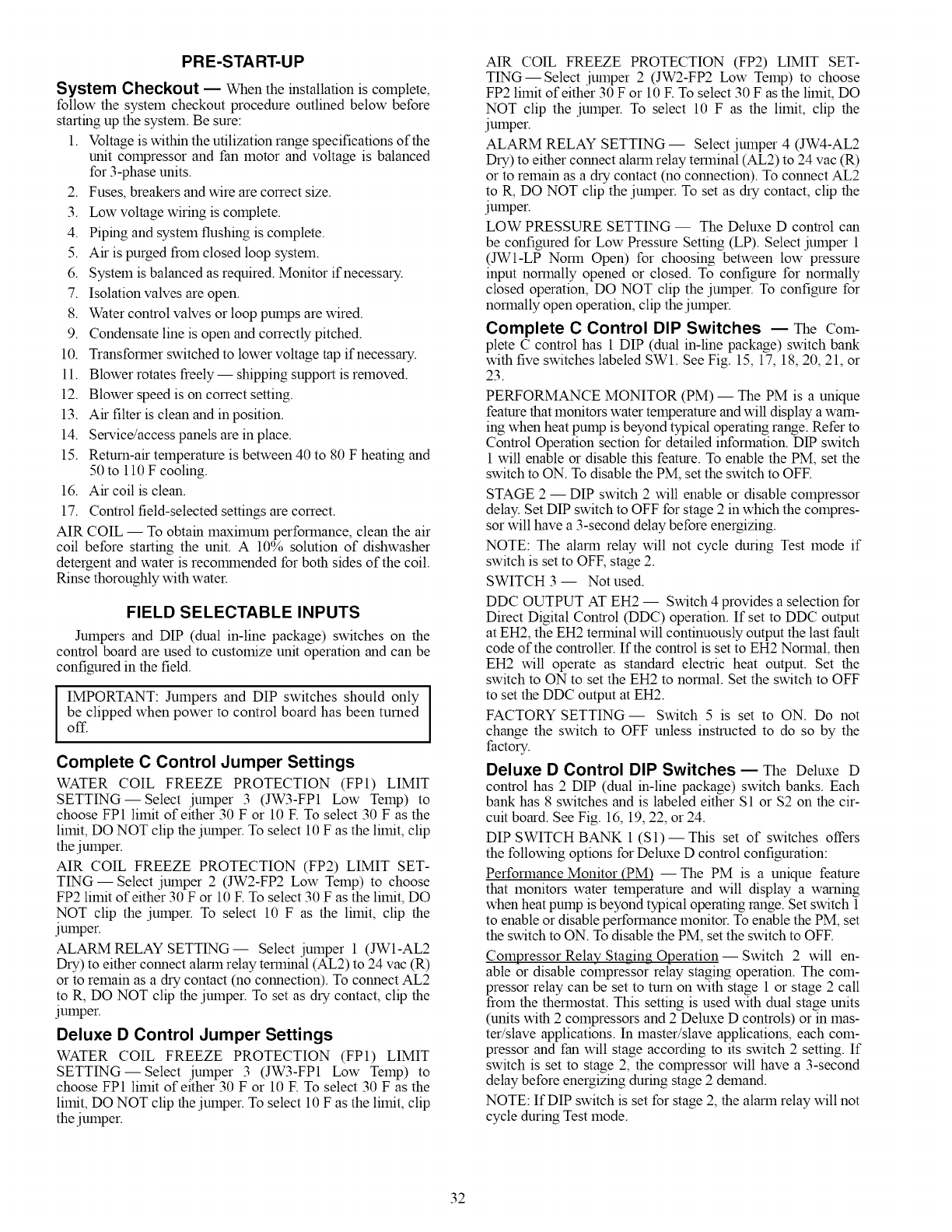
PRE-START-UP
System Checkout EWhen the installation is complete,
follow the system checkout procedure outlined below before
starting up the system. Be sure:
1. Voltage is within the utilization range specifications of the
unit compressor and fan motor and voltage is balanced
for 3-phase units.
2. Fuses, breakers and wire are correct size.
3. Low voltage wiring is complete.
4. Piping and system flushing is complete.
5. Air is purged from closed loop system.
6. System is balanced as required. Monitor if necessary.
7. Isolation valves are open.
8. Water control valves or loop pumps are wired.
9. Condensate line is open and correctly pitched.
10. Transformer switched to lower voltage tap if necessary.
11. Blower rotates freely-- shipping support is removed.
12. Blower speed is on correct setting.
13. Air filter is clean and in position.
14. Service/access panels are in place.
15. Return-air temperature is between 40 to 80 F heating and
50 to 110 F cooling.
16. Air coil is clean.
17. Control field-selected settings are correct.
AIR COIL -- To obtain maximum performance, clean the air
coil before starting the unit. A 10% solution of dishwasher
detergent and water is recolrunended for both sides of the coil.
Rinse thoroughly with water.
FIELD SELECTABLE INPUTS
Jumpers and DIP (dual in-line package) switches on the
control board are used to customize unit operation and can be
configured in the field.
IMPORTANT: Jumpers and DIP switches should only [
be clipped when power to control board has been turned I
off.
Complete C Control Jumper Settings
WATER COIL FREEZE PROTECTION (FP1) LIMIT
SETTING--Select jumper 3 (JW3-FP1 Low Temp) to
choose FP1 limit of either 30 F or 10 E To select 30 F as the
limit, DO NOT clip the jumper. To select 10 F as the limit, clip
the jumper.
AIR COIL FREEZE PROTECTION (FP2) LIMIT SET-
TING- Select jumper 2 (JW2-FP2 Low Temp) to choose
FP2 limit of either 30 F or 10 F. To select 30 F as the limit, DO
NOT clip the jumper. To select 10 F as the limit, clip the
jumper.
ALARM RELAY SETTING-- Select jumper 1 (JIV1-AL2
Dry) to either connect alarm relay terminal (AL2) to 24 vac (R)
or to remain as a dry contact (no connection). To connect AL2
to R, DO NOT clip the jumper. To set as dry contact, clip the
jumper.
Deluxe D Control Jumper Settings
WATER COIL FREEZE PROTECTION (FP1) LIMIT
SETTING--Select jumper 3 (JW3-FP1 Low Temp) to
choose FP1 limit of either 30 F or 10 E To select 30 F as the
limit, DO NOT clip the jumper. To select 10 F as the limit, clip
the jumper.
AIR COIL FREEZE PROTECTION (FP2) LIMIT SET-
TING--Select jumper 2 (JW2-FP2 Low Temp) to choose
FP2 limit of either 30 F or 10 E To select 30 F as the limit, DO
NOT clip the jumper. To select 10 F as the limit, clip the
jumper.
ALARM RELAY SETTING -- Select jumper 4 (JW4-AL2
Dry) to either connect alarm relay terminal (AL2) to 24 vac (R)
or to remain as a dry contact (no connection). To connect AL2
to R, DO NOT clip the jumper. To set as dry contact, clip the
jumper.
LOW PRESSURE SETTING -- The Deluxe D control can
be configured for Low Pressure Setting (LP). Select jumper 1
(JIV1-LP Norm Open) for choosing between low pressure
input normally opened or closed. To configure for normally
closed operation, DO NOT clip the jumper. To configure for
normally open operation, clip the jumper.
Complete C Control DIP Switches EThe Com-
plete C control has 1 DIP (dual in-line package) switch bank
with five switches labeled SWl. See Fig. 15, 17, 18, 20, 21, or
23.
PERFORMANCE MONITOR (PM) -- The PM is a unique
feature that monitors water temperature and will display a wam-
ing when heat pump is beyond typical operating range. Refer to
Control Operation section for detailed information. DIP switch
1 will enable or disable this feature. To enable the PM, set the
switch to ON. To disable the PM, set the switch to OFF.
STAGE 2 -- DIP switch 2 will enable or disable compressor
delay. Set DIP switch to OFF for stage 2 in which the compres-
sor will have a 3-second delay before energizing.
NOTE: The alarm relay will not cycle during Test mode if
switch is set to OFF, stage 2.
SWITCH 3 -- Not used.
DDC OUTPUT AT EH2 -- Switch 4 provides a selection for
Direct Digital Control (DDC) operation. If set to DDC output
at EH2, the EH2 terminal will continuously output the last fault
code of the controller. If the control is set to EH2 Normal, then
EH2 will operate as standard electric heat output. Set the
switch to ON to set the EH2 to normal. Set the switch to OFF
to set the DDC output at EH2.
FACTORY SETTING- Switch 5 is set to ON. Do not
change the switch to OFF unless instructed to do so by the
factory.
Deluxe D Control DIP Switches _The Deluxe D
control has 2 DIP (dual m-line package) switch banks. Each
bank has 8 switches and is labeled either S1 or $2 on the cir-
cuit board. See Fig. 16, 19, 22, or 24.
DIP SWITCH BANK 1 (S1) -- This set of switches offers
the following options for Deluxe D control configuration:
Performance Monitor (PM) --The PM is a unique feature
that monitors water temperature and will display a warning
when heat pump is beyond typical operating range. Set switch 1
to enable or disable performance monitor. To enable the PM, set
the switch to ON. To disable the PM, set the switch to OFF.
Compressor Relay Staging Operation -- Switch 2 will en-
able or disable compressor relay staging operation. The com-
pressor relay can be set to turn on with stage 1 or stage 2 call
from the thermostat. This setting is used with dual stage units
(units with 2 compressors and 2 Deluxe D controls) or in mas-
ter/slave applications. In master/slave applications, each com-
pressor and fan will stage according to its switch 2 setting. If
switch is set to stage 2, the compressor will have a 3-second
delay before energizing during stage 2 demand.
NOTE: If DIP switch is set for stage 2, the alarm relay will not
cycle during Test mode.
32
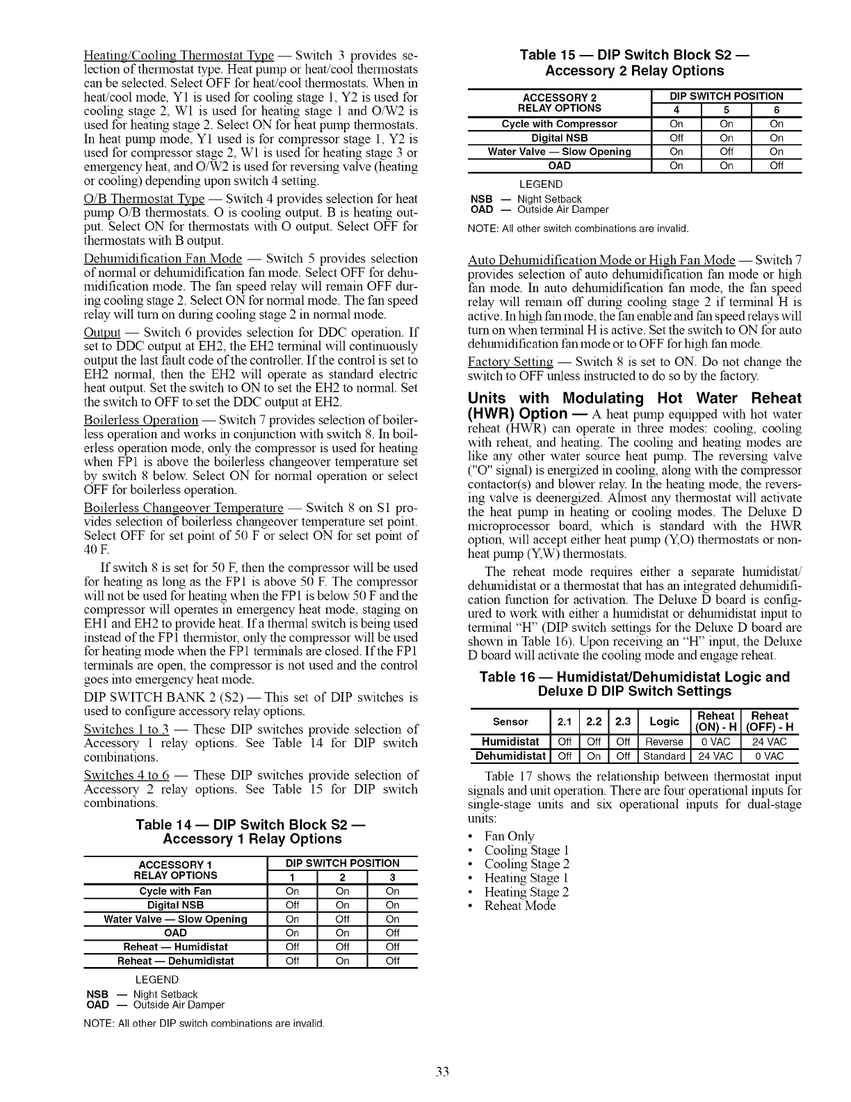
Heating/Cooling Thermostat Type -- Switch 3 provides se-
lection of thermostat type. Heat pump or heat/cool thermostats
can be selected. Select OFF for heat/cool thermostats. When in
heat/cool mode, Y1 is used for cooling stage 1, Y2 is used for
cooling stage 2, Wl is used for heating stage 1 and O/W2 is
used for heating stage 2. Select ON for heat pump thermostats.
In heat pump mode, Y1 used is for compressor stage 1, Y2 is
used for compressor stage 2, Wl is used for heating stage 3 or
emergency heat, and O/W2 is used for reversing valve (heating
or cooling) depending upon switch 4 setting.
O/B Thermostat Type -- Switch 4 provides selection for heat
pump O/B thermostats. O is cooling output. B is heating out-
put. Select ON for thermostats with O output. Select OFF for
thermostats with B output.
Dehumidification Fan Mode -- Switch 5 provides selection
of normal or dehumidification fan mode. Select OFF for dehu-
midification mode. The fan speed relay will remain OFF dur-
ing cooling stage 2. Select ON for normal mode. The fan speed
relay will turn on during cooling stage 2 in normal mode.
Out_put -- Switch 6 provides selection for DDC operation. If
set to DDC output at EH2, the EH2 terminal will continuously
output the last fault code of the controller. If the control is set to
EH2 normal, then the EH2 will operate as standard electric
heat output. Set the switch to ON to set the EH2 to normal. Set
the switch to OFF to set the DDC output at EH2.
Boilerless Operation -- Switch 7 provides selection of boiler-
less operation and works in coNunction with switch 8. In boil-
erless operation mode, only the compressor is used for heating
when FP1 is above the boilerless changeover temperature set
by switch 8 below. Select ON for normal operation or select
OFF for boilerless operation.
Boilerless Changeover Temperature -- Switch 8 on S1 pro-
vides selection of boilerless changeover temperature set point.
Select OFF for set point of 50 F or select ON for set point of
40 E
If switch 8 is set for 50 F, then the compressor will be used
for heating as long as the FP1 is above 50 E The compressor
will not be used for heating when the FP1 is below 50 F and the
compressor will operates in emergency heat mode, staging on
EH1 and EH2 to provide heat. Ifa thermal switch is being used
instead of the FP1 thermistoc only the compressor will be used
for heating mode when the FP1 terminals are closed. If the FP1
terminals are open, the compressor is not used and the control
goes into emergency heat mode.
DIP SWITCH BANK 2 ($2) -- This set of DIP switches is
used to configure accessory relay options.
Switches 1 to 3 -- These DIP switches provide selection of
Accessory 1 relay options. See Table 14 for DIP switch
combinations.
Switches 4 to 6 -- These DIP switches provide
Accessory 2 relay options. See Table 15 for
combinations.
selection of
DIP switch
Table 14 -- DIP Switch Block $2 --
Accessory 1 Relay Options
ACCESSORY 1 DIP SWITCH POSITION
RELAY OPTIONS 1 2 3
Cycle with Fan On On On
Digital NSB Off On On
Water Valve -- Slow Opening On Off On
OAD On On Off
Reheat- Humidistat Off Off Off
Reheat -- Dehumidistat Off On Off
LEGEND
NSB -- Night Setback
OAD -- Outside Air Damper
NOTE: All other DIP switch combinations are invalid.
Table 15 -- DIP Switch Block S2 --
Accessory 2 Relay Options
ACCESSORY 2 DIP SWITCH POSITION
RELAY OPTIONS 4 5 6
Cycle with Compressor On On On
Digital NSB Off On On
Water Valve -- Slow Opening On Off On
OAD On On Off
LEGEND
NSB -- Night Setback
OAD -- Outside Air Damper
NOTE: All other switch combinations are invalid.
Auto Dehumidification Mode or High Fan Mode -- Switch 7
provides selection of auto dehumidification fan mode or high
fan mode. In auto dehumidification fan mode, the fan speed
relay will remain off during cooling stage 2 if terminal H is
active. In high fan mode, the fan enable and fan speed relays will
turn on when terminal H is active. Set the switch to ON for auto
dehumidification fan mode or to OFF for high fan mode.
Factory Setting -- Switch 8 is set to ON. Do not change the
switch to OFF unless instructed to do so by the factory.
Units with Modulating Hot Water Reheat
(HWR) Option EA heat pump equipped with hot water
reheat (HWR) can operate in three modes: cooling, cooling
with reheat, and heating. The cooling and heating modes are
like any other water source heat pump. The reversing valve
("O" signal) is energized in cooling, along with the compressor
contactor(s) and blower relay. In the heating mode, the revers-
ing valve is deenergized. Almost any thermostat will activate
the heat pump in heating or cooling modes. The Deluxe D
microprocessor board, which is standard with the HWR
option, will accept either heat pump (Y,O) thermostats or non-
heat pump (Y,W) thermostats.
The reheat mode requires either a separate humidistat/
dehumidistat or a thermostat that has an integrated dehumidifi-
cation function for activation. The Deluxe D board is config-
ured to work with either a humidistat or dehumidistat input to
terminal '°H" (DIP switch settings for the Deluxe D board are
shown in Table 16). Upon receiving an '°H" input, the Deluxe
D board will activate the cooling mode and engage reheat.
Table 16- Humidistat/Dehumidistat Logic and
Deluxe D DIP Switch Settings
Reheat Reheat
Sensor 2.1 2.2 2.3 Logic (ON)- H (OFF)- H
Humidistat Off Off Off Reverse 0 VAC 24 VAC
Dehumidistat Off On Off Standard 24 VAC 0 VAC
Table 17 shows the relationship between thermostat input
signals and unit operation. There are four operational inputs for
single-stage units and six operational inputs for dual-stage
units:
• Fan Only
• Cooling Stage 1
• Cooling Stage 2
• Heating Stage 1
• Heating Stage 2
• Reheat Mode
33
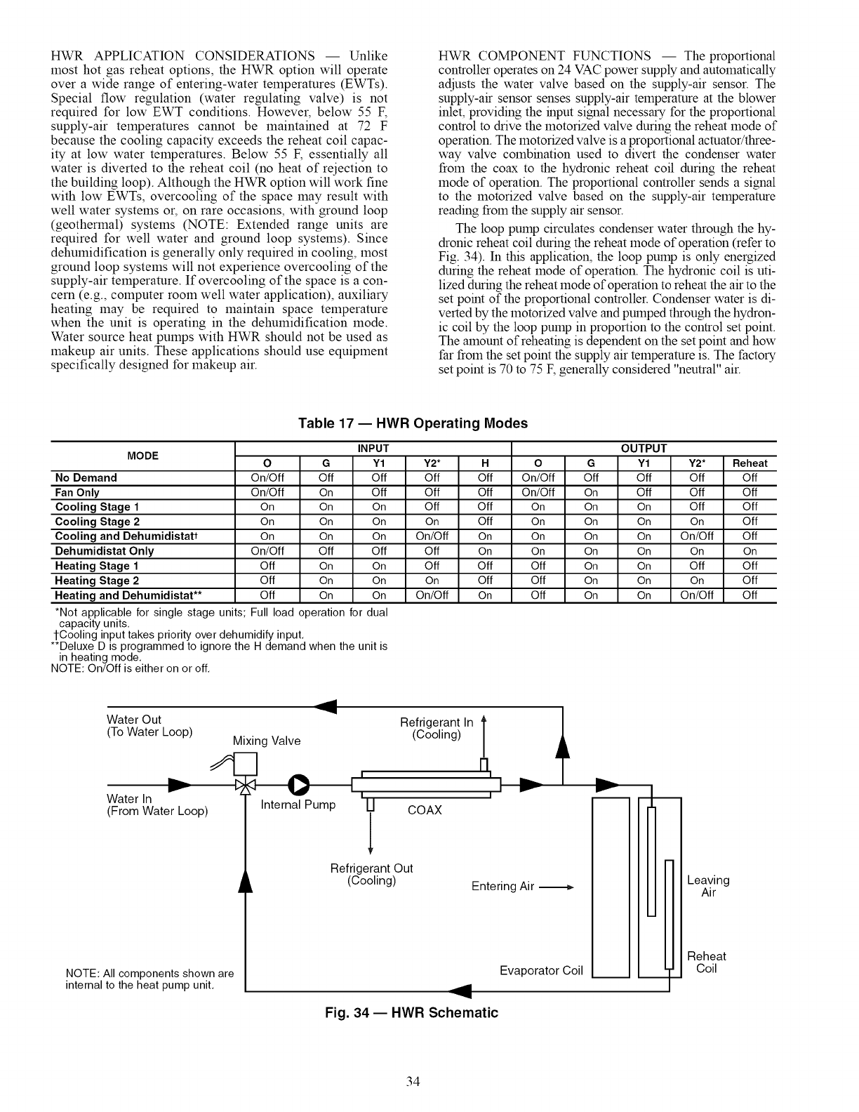
HWRAPPLICATIONCONSIDERATIONS-- Unlike
mosthotgasreheatoptions,theHWRoptionwill operate
overawiderangeof entering-watertemperatures(EWTs).
Specialflow regulation(waterregulatingvalve)is not
requiredfor lowEWTconditions.However,below55F,
supply-airtemperaturescannotbemaintainedat 72 F
becausethecoolingcapacityexceedsthereheatcoilcapac-
ity at lowwatertemperatures.Below55F,essentiallyall
waterisdivertedtothereheatcoil(noheatofrejectionto
thebuildingloop).AlthoughtheHWRoptionwillworkfine
withlowEWTs,overcoolingof thespacemayresultwith
wellwatersystemsor,onrareoccasions,withgroundloop
(geothermal)systems(NOTE:Extendedrangeunitsare
requiredfor wellwaterandgroundloopsystems).Since
dehumidificationisgenerallyonlyrequiredincooling,most
groundloopsystemswillnotexperienceovercoolingof the
supply-airtemperature.If overcoolingofthespaceisacon-
cern(e.g.,computerroomwellwaterapplication),auxiliary
heatingmayberequiredto maintainspacetemperature
whentheunitisoperatingin thedehumidificationmode.
WatersourceheatpumpswithHWRshouldnotbeusedas
makeupairunits.Theseapplicationsshoulduseequipment
specificallydesignedformakeupair.
HWRCOMPONENTFUNCTIONS-- Theproportional
controlleroperateson24VACpowersupplyandautomatically
adjuststhewatervalvebasedonthesupply-airsensor.The
supply-airsensorsensessupply-airtemperatureattheblower
inlet,providingtheinputsignalnecessaryfortheproportional
controltodrivethemotorizedvalveduringthereheatmodeof
operation.Themotorizedvalveisaproportionalactuator/three-
wayvalvecombinationusedto divertthecondenserwater
fromthecoaxto thehydronicreheatcoilduringthereheat
modeof operation.Theproportionalcontrollersendsasignal
to themotorizedvalvebasedonthesupply-airtemperature
readingfromthesupplyairsensor.
Thelooppumpcirculatescondenserwaterthroughthehy-
dronicreheatcoilduringthereheatmodeofoperation(referto
Fig.34).In thisapplication,thelooppumpisonlyenergized
duringthereheatmodeofoperation.Thehydroniccoilisuti-
lizedduringthereheatmodeofoperationtoreheattheairtothe
setpointoftheproportionalcontroller.Condenserwaterisdi-
vertedbythemotorizedvalveandpumpedthroughthehydron-
iccoilbythelooppumpinproportiontothecontrolsetpoint.
Theamountofreheatingisdependentonthesetpointandhow
farfromthesetpointthesupplyairtemperatureis.Thefactory
setpointis70to75F,generallyconsidered"neutral"air.
Table 17- HWR Operating Modes
MODE
No Demand
Fan Only
Cooling Stage 1
Cooling Stage 2
Cooling and Dehumidistatt
Dehumidistat Only
Heating Stage 1
Heating Stage 2
Heating and Dehumidistat**
INPUT OUTPUT
O G Y1 Y2* H O G Y1
On/Off Off Off Off Off On/Off Off Off
On/Off On Off Off Off On/Off On Off
On On On Off Off On On On
On On On On Off On On On
On On On On/Off On On On On
On/Off Off Off Off On On On On
Off On On Off Off Off On On
Off On On On Off Off On On
Off On On On/Off On Off On On
*Not applicable for single stage units; Full load operation for dual
capacity units.
1-Cooling input takes priority over dehumidify input.
**Deluxe D is programmed to ignore the H demand when the unit is
in heating mode.
NOTE: On/Off is either on or off.
Y2*
Off
Off
Off
On
On/Off
On
Off
On
On/Off
Reheat
Off
Off
Off
Off
Off
On
Off
Off
Off
Water In
(From Water Loop)
Water Out Refrigerant In
(To Water Loop) Mixing Valve (Cooling)
Internal Pump U COAX
NOTE: All components shown are
internal to the heat pump unit.
Refrigerant Out
(Cooling) Entering Air -_
Evaporator Coil
Fig. 34 -- HWR Schematic
Leaving
Air
Reheat
Coil
34
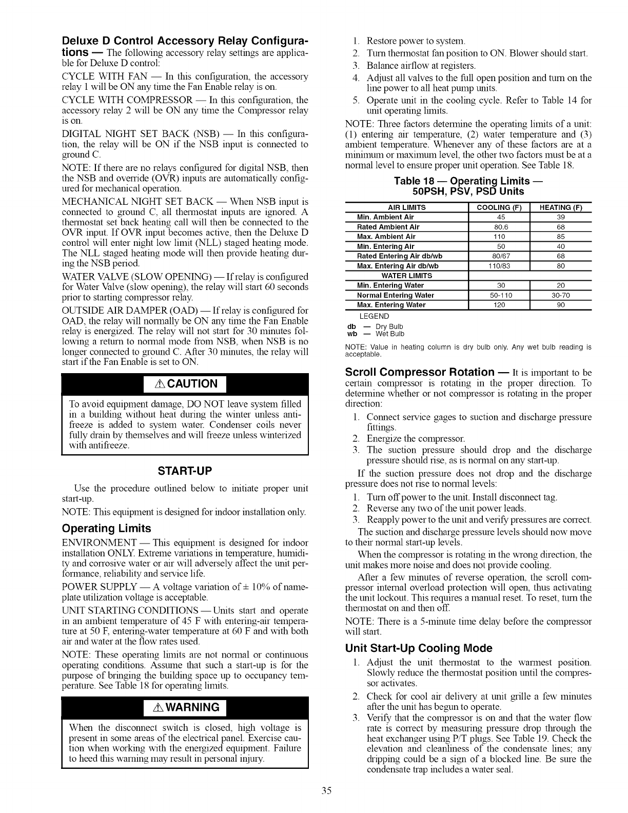
Deluxe D Control Accessory Relay Configura-
tions -- The following accessory relay settings are applica-
ble for Deluxe D control:
CYCLE WITH FAN -- In this configuration, the accessory
relay 1 will be ON any trine the Fan Enable relay is on.
CYCLE WITH COMPRESSOR -- In this configuration, the
accessory relay 2 will be ON any time the Compressor relay
IS on.
DIGITAL NIGHT SET BACK (NSB) -- In this configura-
tion, the relay will be ON if the NSB input is connected to
ground C.
NOTE: If there are no relays configured for digital NSB, then
the NSB and override (OVR) inputs are automatically config-
ured for mechanical operation.
MECHANICAL NIGHT SET BACK -- When NSB input is
connected to ground C, all thermostat inputs are ignored. A
thermostat set back heating call will then be connected to the
OVR input. If OVR input becomes active, then the Deluxe D
control will enter night low limit (NLL) staged heating mode.
The NLL staged heating mode will then provide heating dur-
ing the NSB period.
WATER VALVE (SLOW OPENING) -- If relay is configured
for Water Valve (slow opening), the relay will start 60 seconds
prior to starting compressor relay.
OUTSIDE AIR DAMPER (OAD) -- If relay is configured for
OAD, the relay will normally be ON any time the Fan Enable
relay is energized. The relay will not start for 30 minutes fol-
lowing a return to normal mode from NSB, when NSB is no
longer connected to ground C. After 30 minutes, the relay will
start if the Fan Enable is set to ON.
To avoid equipment damage, DO NOT leave system filled
in a building without heat during the winter unless anti-
freeze is added to system water. Condenser coils never
fully drain by themselves and will freeze unless winterized
with antifreeze.
START-UP
Use the procedure outlined below to initiate proper unit
start-up.
NOTE: This equipment is designed for indoor installation only.
Operating Limits
ENVIRONMENT- This equipment is designed for indoor
installation ONLY Extreme variations in temperature, humidi-
ty and corrosive water or air will adversely affect the unit per-
formance, reliability and service life.
POWER SUPPLY -- A voltage variation of+ 10% of name-
plate utilization voltage is acceptable.
UNIT START1NG CONDITIONS--Units start and operate
in an ambient temperature of 45 F with entering-air tempera-
ture at 50 F, entering-water temperature at 60 F and with both
air and water at the flow rates used.
NOTE: These operating lrinits are not normal or continuous
operating conditions. Assume that such a start-up is for the
purpose of bringing the building space up to occupancy tem-
perature. See Table 18 for operating limits.
When the disconnect switch is closed, high voltage is
present in some areas of the electrical panel. Exercise cau-
tion when working with the energized equipment. Failure
to heed this warning may result in personal iniury.
1. Restore power to system.
2. Turn thermostat fan position to ON. Blower should start.
3. Balance airflow at registers.
4. Adjust all valves to the full open position and turn on the
line power to all heat pump units.
5. Operate unit in the cooling cycle. Refer to Table 14 for
unit operating lrinits.
NOTE: Three factors determine the operating limits of a unit:
(1) entering air temperature, (2) water temperature and (3)
ambient temperature. Whenever any of these factors are at a
minimum or maximum level, the other two factors must be at a
normal level to ensure proper unit operation. See Table 18.
Table 18 nOperating Limits --
50PSH, PSV, PSD Units
AIR LIMITS
Min. Ambient Air
Rated Ambient Air
Max. Ambient Air
Min. Entering Air
Rated Entering Air db/wb
Max. Entering Air db/wb
WATER LIMITS
Min. Entering Water
Normal Entering Water
Max. Entering Water
LEGEND
db -- Dry Bulb
wb -- Wet Bulb
COOLING (F) HEATING (F)
45 39
80.6 68
110 85
50 40
80/67 68
110/83 80
30 20
50-110 30-70
120 90
NOTE: Value in heating column is dry bulb only. Any wet bulb reading is
acceptable.
Scroll Compressor Rotation EIt is important to be
certain compressor is rotating in the proper direction. To
determine whether or not compressor is rotating in the proper
direction:
1. Connect service gages to suction and discharge pressure
fittings.
2. Energize the compressor.
3. The suction pressure should drop and the discharge
pressure should rise, as is normal on any start-up.
If the suction pressure does not drop and the discharge
pressure does not rise to normal levels:
1. Turn offpower to the unit. Install disconnect tag.
2. Reverse any two of the unit power leads.
3. Reapply power to the unit and verify pressures are correct.
The suction and discharge pressure levels should now move
to their normal start-up levels.
When the compressor is rotating in the wrong direction, the
unit makes more noise and does not provide cooling.
After a few minutes of reverse operation, the scroll com-
pressor internal overload protection will open, thus activating
the unit lockout. This requires a manual reset. To reset, turn the
thermostat on and then off.
NOTE: There is a 5-minute time delay before the compressor
will start.
Unit Start-Up Cooling Mode
1. Adjust the unit thermostat to the warmest position.
Slowly reduce the thermostat position until the compres-
sor activates.
2.
3.
Check for cool air delivery at unit grille a few minutes
after the unit has begun to operate.
Verify that the compressor is on and that the water flow
rate is correct by measuring pressure drop through the
heat exchanger using P/T plugs. See Table 19. Check the
elevation and cleanliness of the condensate lines; any
dripping could be a sign of a blocked line. Be sure the
condensate trap includes a water seal.
35
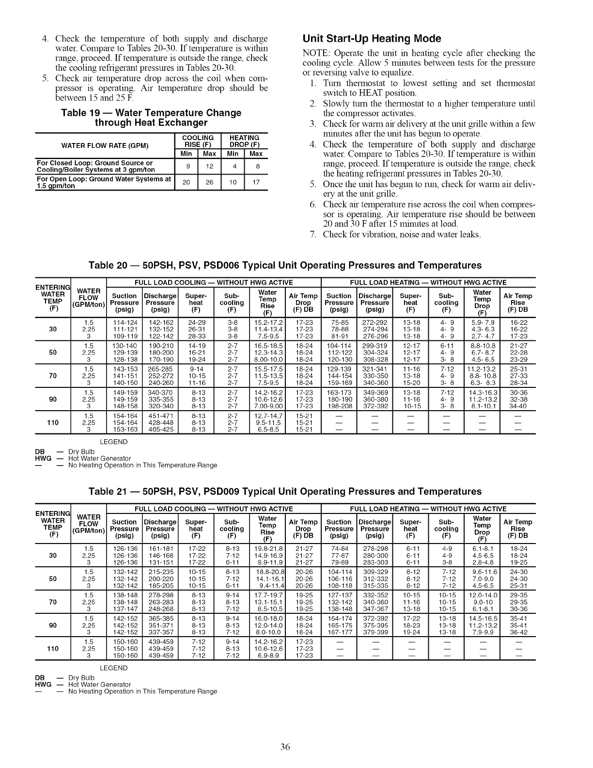
4. Checkthetemperatureof bothsupplyanddischarge
water.ComparetoTables20-30.If temperatureiswithin
range,proceed.Iftemperatureisoutsidetherange,check
thecoolingrefrigerantpressuresinTables20-30.
5. Checkairtemperaturedropacrossthecoilwhencom-
pressoris operating.Air temperaturedropshouldbe
between15and25E
Table 19 -- Water Temperature Change
through Heat Exchanger
WATER FLOW RATE (GPM)
For Closed Loop: Ground Source or
Cooling/Boiler Systems at 3 gpm/ton
For Open Loop: Ground Water Systems at
1.5 gpm/ton
COOLING
RISE (F)
Min Max
9 12
20 26
HEATING
DROP (F)
Min Max
4 8
lO 17
Unit Start-Up Heating Mode
NOTE: Operate the unit in heating cycle after checking the
cooling cycle. Allow 5 minutes between tests for the pressure
or reversing valve to equalize.
1. Turn thermostat to lowest setting and set thermostat
switch to HEAT position.
2. Slowly turn the thermostat to a higher temperature until
the compressor activates.
3. Check for warm air delivery at the unit grille within a few
minutes after the unit has begun to operate.
4. Check the temperature of both supply and discharge
water. Compare to Tables 20-30. If temperature is within
range, proceed. If temperature is outside the range, check
the heating refrigerant pressures in Tables 20-30.
5. Once the unit has begun to run, check for warm air deliv-
ery at the unit grille.
6. Check air temperature rise across the coil when compres-
sor is operating. Air temperature rise should be between
20 and 30 F after 15 minutes at load.
7. Check for vibration, noise and water leaks.
Table 20 -- 50PSH, PSV, PSD006 Typical Unit Operating Pressures and Temperatures
FULL LOAD COOLING --WITHOUT HWG ACTIVE FULL LOAD HEATING -- WITHOUT HWG ACTIVE
ENTERING
WATER WATER Water Water
FLOW Suction Discharge Super- Sub- Temp Air Temp Suction Discharge Super- Sub- Temp Air Temp
Rise
TEMP (GPM/ton) Pressure Pressure heat cooling Rise Drop Pressure Pressure heat cooling Drop (F) DB
(F) (psig) (psig) (F) (F) (F) (F) DB (psig) (psig) (F) (F) (F)
1.5 114-124 142-162 24-29 3-8 15.2-17.2 17-23 75-85 272-292 13-18 4- 9 5.9- 7.9 16-22
30 2.25 111-121 132-152 26-31 3-8 11.4-13.4 17-23 78-88 274-294 13-18 4- 9 4.3-6.3 16-22
3 109-119 122-142 28-33 3-8 7.5-9.5 17-23 81-91 276-296 13-18 4- 9 2.7-4.7 17-23
1.5 130-140 190-210 14-19 2-7 16.5-18.5 18-24 104-114 299-319 12-17 6-11 8.8-10.8 21-27
50 2.25 129-139 180-200 16-21 2-7 12.3-14.3 18-24 112-122 304-324 12-17 4- 9 6.7-8.7 22-28
3 128-138 170-190 19-24 2-7 8.00-10.0 18-24 120-130 308-328 12-17 3- 8 4.5- 6.5 23-29
1.5 143-153 265-285 9-14 2-7 15.5-17.5 18-24 129-139 321-341 11-16 7-12 11.2-13.2 25-31
70 2.25 141-151 252-272 10-15 2-7 11.5-13.5 18-24 144-154 330-350 13-18 4- 9 8.8- 10.8 27-33
3 140-150 240-260 11-16 2-7 7.5-9.5 18-24 159-169 340-360 15-20 3- 8 6.3- 8.3 28-34
1.5 149-159 340-370 8-13 2-7 14.2-16.2 17-23 163-173 349-369 13-18 7-12 14.3-16.3 30-36
90 2.25 149-159 335-355 8-13 2-7 10.6-12.6 17-23 180-190 360-380 11-16 4- 9 11.2-13.2 32-38
3 148-158 320-340 8-13 2-7 7.00-9.00 17-23 198-208 372-392 10-15 3- 8 8.1-10.1 34-40
1.5 154-164 451-471 8-13 2-7 12.7-14.7 15-21 ......
110 2.25 154-164 428-448 8-13 2-7 9.5-11.5 15-21 ......
3 153-163 405-425 8-13 2-7 6.5-8.5 15-21 ......
LEGEND
DB -- Dry Bulb
HWG -- Hot Water Generator
-- -- No Heating Operation in This Temperature Range
Table 21 -- 50PSH, PSV, PSD009 Typical Unit Operating Pressures and Temperatures
FULL LOAD COOLING --WITHOUT HWG ACTIVE FULL LOAD HEATING --WITHOUT HWG ACTIVE
ENTERING WATER Water
WATER FLOW Suction Discharge Super- Sub- Temp Air Temp Suction Discharge Super- Sub-
TEMP (GPM/ton) Pressure Pressure heat cooling Drop Pressure Pressure heat cooling
Rise
(F) (psig) (psig) (F) (F) (F) (F) DB (psig) (psig) (F) (F)
1.5 126-136 161-181 17-22 8-13 19.8-21.8 21-27 74-84 278-298 6-11 4-9
30 2.25 126-136 146-166 17-22 7-12 14.9-16.9 21-27 77-87 280-300 6-11 4-9
3 126-136 131-151 17-22 6-11 9.9-11.9 21-27 79-89 283-303 6-11 3-8
1.5 132-142 215-235 10-15 8-13 18.8-20.8 20-26 104-114 309-329 8-12 7-12
50 2.25 132-142 200-220 10-15 7-12 14.1-16.1 20-26 106-116 312-332 8-12 7-12
3 132-142 185-205 10-15 6-11 9.4-11.4 20-26 108-118 315-335 8-12 7-12
1.5 138-148 278-298 8-13 9-14 17.7-19.7 19-25 127-137 332-352 10-15 10-15
70 2.25 138-148 263-283 8-13 8-13 13.1-15.1 19-25 132-142 340-360 11-16 10-15
3 137-147 248-268 8-13 7-12 8.5-10.5 19-25 138-148 347-367 13-18 10-15
1.5 142-152 365-385 8-13 9-14 16.0-18.0 18-24 164-174 372-392 17-22 13-18
90 2.25 142-152 351-371 8-13 8-13 12.0-14.0 18-24 165-175 375-395 18-23 13-18
3 142-152 337-357 8-13 7-12 8.0-10.0 18-24 167-177 379-399 19-24 13-18
1.5 150-160 439-459 7-12 9-14 14.2-16.2 17-23 ....
110 2.25 150-160 439-459 7-12 8-13 10.6-12.6 17-23 ....
3 150-160 439-459 7-12 7-12 6.9-8.9 17-23 ....
LEGEND
DB -- Dry Bulb
HWG -- Hot Water Generator
-- -- No Heating Operation in This Temperature Range
Water
Temp
Drop
(F)
6.t-8.1
4.5-6.5
2.8-4.8
9.6-11.6
7.0-9.0
4.5-6.5
12.0-14.0
9.0-10
6.1-8.1
14.5-16.5
11.2-13.2
7.9-9.9
Air Temp
Rise
(F) DB
18-24
18-24
19-25
24-30
24-30
25-31
29-35
29-35
30-36
35-41
35-41
36-42
m m
m m
m m
36
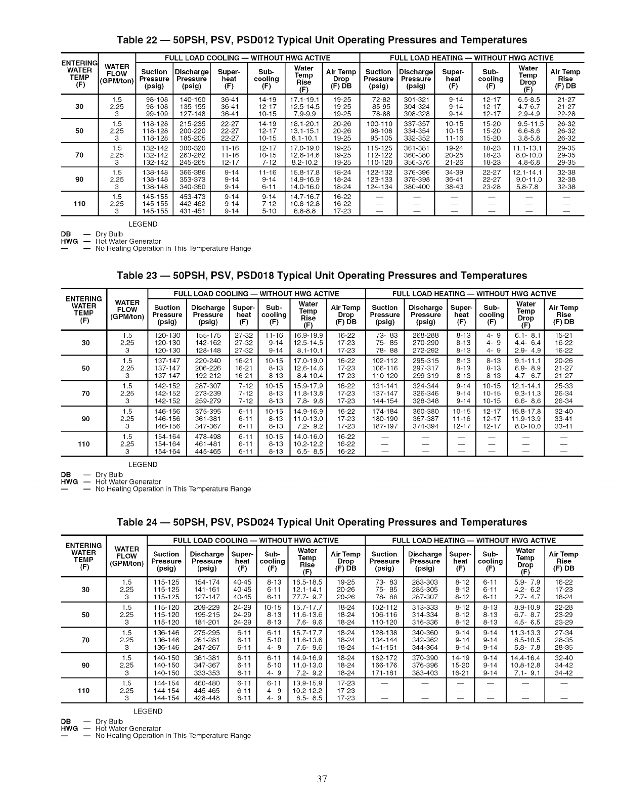
Table 22 -- 50PSH, PSV, PSD012 Typical Unit Operating Pressures and Temperatures
ENTERING
WATER
TEMP
(F)
30
50
70
90
110
FULL LOAD COOLING -- WITHOUT HWG ACTIVE FULL LOAD HEATING -- WITHOUT HWG ACTIVE
WATER Water Water
FLOW Suction Discharge Super- Sub- Temp Air Temp Suction Discharge Super- Sub- Temp
(GPM/ton) Pressure Pressure heat cooling Rise Drop Pressure Pressure heat cooling Drop
(psig) (psig) (F) (F) (F) (F) DB (psig) (psig) (F) (F) (F)
1.5 98-108 140-160 36-41 14-19 17.1-19.1 19-25 72-82 301-321 9-14 12-17 6.5-8.5
2.25 98-108 135-155 36-41 12-17 12.5-14.5 19-25 85-95 304-324 9-14 12-17 4.7-6.7
3 99-109 127-148 36-41 10-15 7.9-9.9 19-25 78-88 308-328 9-14 12-17 2.9-4.9
1.5 118-128 215-235 22-27 14-19 18.1-20.1 20-26 100-110 337-357 10-15 15-20 9.5-11.5
2.25 118-128 200-220 22-27 12-17 13.1-15.1 20-26 98-108 334-354 10-15 15-20 6.6-8.6
3 118-128 185-205 22-27 10-15 8.1-10.1 19-25 95-105 332-352 11-16 15-20 3.8-5.8
1.5 132-142 300-320 11-16 12-17 17.0-19.0 19-25 115-125 361-381 19-24 18-23 11.1-13.1
2.25 132-142 263-282 11-16 10-15 12.6-14.6 19-25 112-122 360-380 20-25 18-23 8.0-10.0
3 132-142 245-265 12-17 7-12 8.2-10.2 19-25 110-120 356-376 21-26 18-23 4.8-6.8
1.5 138-148 366-386 9-14 11-16 15.8-17.8 18-24 122-132 376-396 34-39 22-27 12.1-14.1
2.25 138-148 353-373 9-14 9-14 14.9-16.9 18-24 123-133 378-398 36-41 22-27 9.0-11.0
3 138-148 340-360 9-14 6-11 14.0-16.0 18-24 124-134 380-400 38-43 23-28 5.8-7.8
1.5 145-155 453-473 9-14 9-14 14.7-16.7 16-22 ....
2.25 145-155 442-462 9-14 7-12 10.8-12.8 16-22 ....
3 145-155 431-451 9-14 5-10 6.8-8.8 17-23 ....
LEGEND
DB -- Dry Bulb
HWG -- Hot Water Generator
-- -- No Heating Operation in This Temperature Range
Air Temp
Rise
(F) DB
21-27
21-27
22-28
26-32
26-32
26-32
29-35
29-35
29-35
32-38
32-38
32-38
m m
m m
m m
Table 23 -- 50PSH, PSV, PSD018 Typical Unit Operating Pressures and Temperatures
FULL LOAD COOLING -- WITHOUT HWG ACTIVE FULL LOAD HEATING -- WITHOUT HWG ACTIVE
ENTERING
WATER WATER Water Water
FLOW Suction Discharge Super- Sub- Temp Air Temp Suction Discharge Super- Sub- Temp Air Temp
Drop Pressure Pressure heat cooling Drop Rise
TEMP(F) (GPM/ton) Pressure(psig)Pressure(psig) heat(F) cooling(F) Rise(F) (F) DB (psig) (psig) (F) (F) (F) (F) DB
1.5 120-130 155-175 27-32 11-16 16.9-19.9 16-22 73- 83 268-288 8-13 4- 9 6.1- 8.1 15-21
30 2.25 120-130 142-162 27-32 9-14 12.5-14.5 17-23 75- 85 270-290 8-13 4- 9 4.4- 6.4 16-22
3 120-130 128-148 27-32 9-14 8.1-10.1 17-23 78- 88 272-292 8-13 4- 9 2.9- 4.9 16-22
1.5 137-147 220-240 16-21 10-15 17.0-19.0 16-22 102-112 295-315 8-13 8-13 9.1-11.1 20-26
50 2.25 137-147 206-226 16-21 8-13 12.6-14.6 17-23 106-116 297-317 8-13 8-13 6.9- 8.9 21-27
3 137-147 192-212 16-21 8-13 8.4-10.4 17-23 110-120 299-319 8-13 8-13 4.7- 6.7 21-27
1.5 142-152 287-307 7-12 10-15 15.9-17.9 16-22 131-141 324-344 9-14 10-15 12.1-14.1 25-33
70 2.25 142-152 273-239 7-12 8-13 11.8-13.8 17-23 137-147 326-346 9-14 10-15 9.3-11.3 26-34
3 142-152 259-279 7-12 8-13 7.8- 9.8 17-23 144-154 328-348 9-14 10-15 6.6- 8.6 26-34
1.5 146-156 375-395 6-11 10-15 14.9-16.9 16-22 174-184 360-380 10-15 12-17 15.8-17.8 32-40
90 2.25 146-156 361-381 6-11 8-13 11.0-13.0 17-23 180-190 367-387 11-16 12-17 11.9-13.9 33-41
3 146-156 347-367 6-11 8-13 7.2- 9.2 17-23 187-197 374-394 12-17 12-17 8.0-10.0 33-41
1.5 154-164 478-498 6-11 10-15 14.0-16.0 16-22 ......
110 2.25 154-164 461-481 6-11 8-13 10.2-12.2 16-22 ......
3 154-164 445-465 6-11 8-13 6.5- 8.5 16-22 ......
LEGEND
DB -- Dry Bulb
HWG -- Hot Water Generator
-- -- No Heating Operation in This Temperature Range
Table 24 -- 50PSH, PSV, PSD024 Typical Unit Operating Pressures and Temperatures
FULL LOAD COOLING -- WITHOUT HWG ACTIVE FULL LOAD HEATING -- WITHOUT HWG ACTIVE
ENTERING WATER Water Water
WATER FLOW Suction Discharge Super- Sub- Air Temp Suction Discharge Super- Sub- Air Temp
TEMP (GPM/ton) Pressure Pressure heat cooling Temp Drop Pressure Pressure heat cooling Temp Rise
Rise Drop (F) DB
(F) (psig) (psig) (F) (F) (F) (F) DB (psig) (psig) (F) (F) (F)
1.5 115-125 154-174 40-45 8-13 16.5-18.5 19-25 73- 83 283-303 8-12 6-11 5.9- 7.9 16-22
30 2.25 115-125 141-161 40-45 6-11 12.1-14.1 20-26 75- 85 285-305 8-12 6-11 4.2- 6.2 17-23
3 115-125 127-147 40-45 6-11 77.7- 9.7 20-26 78- 88 287-307 8-12 6-11 2.7- 4.7 18-24
1.5 115-120 209-229 24-29 10-15 15.7-17.7 18-24 102-112 313-333 8-12 8-13 8.9-10.9 22-28
50 2.25 115-120 195-215 24-29 8-13 11.6-13.6 18-24 106-116 314-334 8-12 8-13 6.7- 8.7 23-29
3 115-120 181-201 24-29 8-13 7.6- 9.6 18-24 110-120 316-336 8-12 8-13 4.5- 6.5 23-29
1.5 136-146 275-295 6-11 6-11 15.7-17.7 18-24 128-138 340-360 9-14 9-14 11.3-13.3 27-34
70 2.25 136-146 261-281 6-11 5-10 11.6-13.6 18-24 134-144 342-362 9-14 9-14 8.5-10.5 28-35
3 136-146 247-267 6-11 4- 9 7.6- 9.6 18-24 141-151 344-364 9-14 9-14 5.8- 7.8 28-35
1.5 140-150 361-381 6-11 6-11 14.9-16.9 18-24 162-172 370-390 14-19 9-14 14.4-16.4 32-40
90 2.25 140-150 347-367 6-11 5-10 11.0-13.0 18-24 166-176 376-396 15-20 9-14 10.8-12.8 34-42
3 140-150 333-353 6-11 4- 9 7.2- 9.2 18-24 171-181 383-403 16-21 9-14 7.1- 9.1 34-42
1.5 144-154 460-480 6-11 6-11 13.9-15.9 17-23 ......
110 2.25 144-154 445-465 6-11 4- 9 10.2-12.2 17-23 ......
3 144-154 428-448 6-11 4- 9 6.5- 8.5 17-23 ......
LEGEND
DB -- Dry Bulb
HWG -- Hot Water Generator
-- -- No Heating Operation in This Temperature Range
37
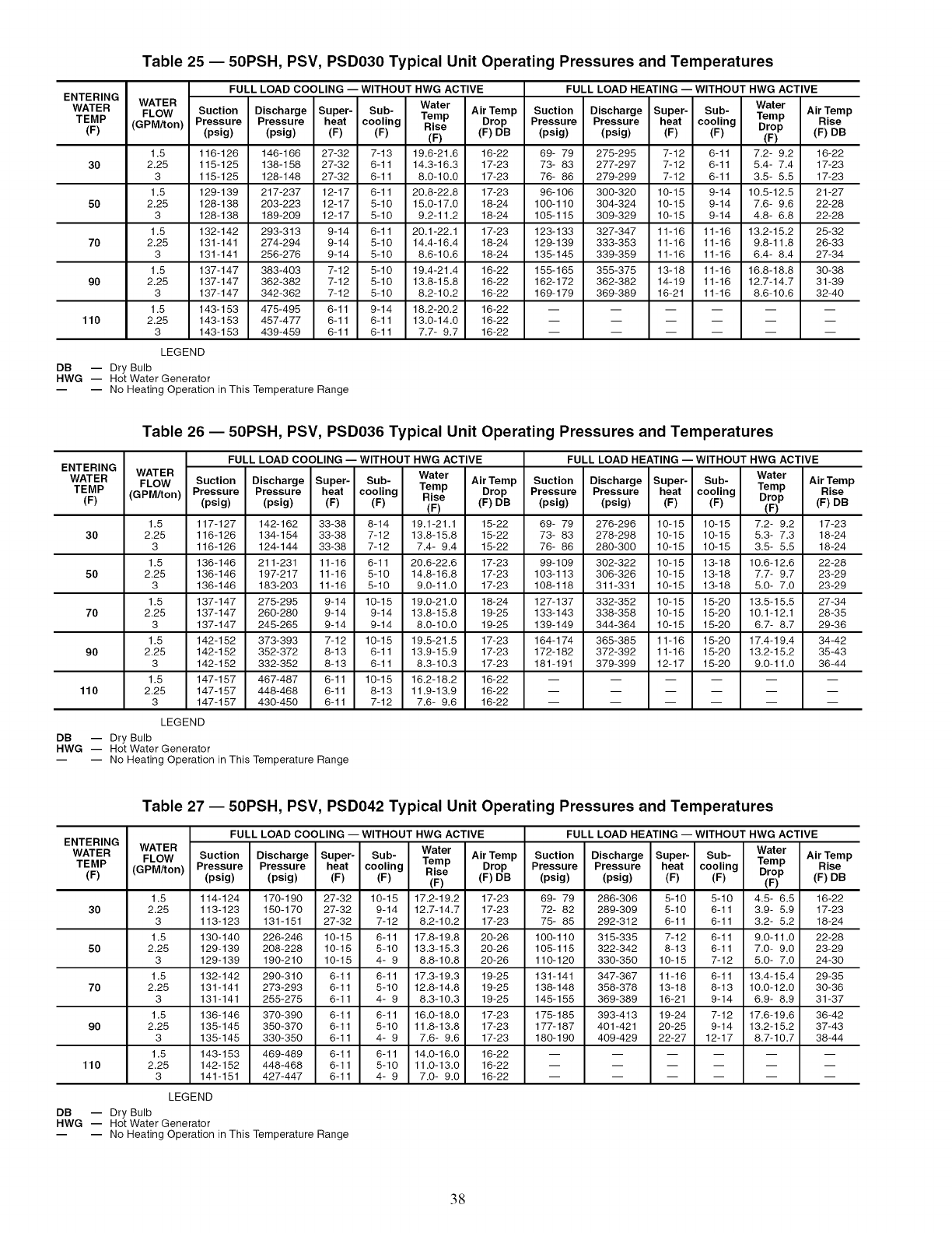
Table 25 -- 50PSH, PSV, PSD030 Typical Unit Operating Pressures and Temperatures
FULL LOAD COOLING -- WITHOUT HWG ACTIVE FULL LOAD HEATING -- WITHOUT HWG ACTIVE
ENTERING
WATER WATER Water Water
FLOW Suction Discharge Super- Sub- Temp Air Temp Suction Discharge Super- Sub- Temp Air Temp
Drop Pressure Pressure heat cooling Drop Rise
TEMP(F) (GPM/ton) Pressure(psig)Pressure(psig) heat(F) cooling(F) Rise(F) (F) DB (psig) (psig) (F) (F) (F) (F) DB
1.5 116-126 146-166 27-32 7-13 19.6-21.6 16-22 69- 79 275-295 7-12 6-11 7.2- 9.2 16-22
30 2.25 115-125 138-158 27-32 6-11 14.3-16.3 17-23 73- 83 277-297 7-12 6-11 5.4- 7.4 17-23
3 115-125 128-148 27-32 6-11 8.0-10.0 17-23 76- 86 279-299 7-12 6-11 3.5- 5.5 17-23
1.5 129-139 217-237 12-17 6-11 20.8-22.8 17-23 96-106 300-320 10-15 9-14 10.5-12.5 21-27
50 2.25 128-138 203-223 12-17 5-10 15.0-17.0 18-24 100-110 304-324 10-15 9-14 7.6- 9.6 22-28
3 128-138 189-209 12-17 5-10 9.2-11.2 18-24 105-115 309-329 10-15 9-14 4.8- 6.8 22-28
1.5 132-142 293-313 9-14 6-11 20.1-22.1 17-23 123-133 327-347 11-16 11-16 13.2-15.2 25-32
70 2.25 131-141 274-294 9-14 5-10 14.4-16.4 18-24 129-139 333-353 11-16 11-16 9.8-11.8 26-33
3 131-141 256-276 9-14 5-10 8.6-10.6 18-24 135-145 339-359 11-16 11-16 6.4- 8.4 27-34
1.5 137-147 383-403 7-12 5-10 19.4-21.4 16-22 155-165 355-375 13-18 11-16 16.8-18.8 30-38
90 2.25 137-147 362-382 7-12 5-10 13.8-15.8 16-22 162-172 362-382 14-19 11-16 12.7-14.7 31-39
3 137-147 342-362 7-12 5-10 8.2-10.2 16-22 169-179 369-389 16-21 11-16 8.6-10.6 32-40
1.5 143-153 475-495 6-11 9-14 18.2-20.2 16-22 ......
110 2.25 143-153 457-477 6-11 6-11 13.0-14.0 16-22 ......
3 143-153 439-459 6-11 6-11 7.7- 9.7 16-22 ......
LEGEND
DB -- Dry Bulb
HWG -- Hot Water Generator
-- -- No Heating Operation in This Temperature Range
Table 26 -- 50PSH, PSV, PSD036 Typical Unit Operating Pressures and Temperatures
FULL LOAD COOLING -- WITHOUT HWG ACTIVE FULL LOAD HEATING -- WITHOUT HWG ACTIVE
ENTERING WATER Water Water
WATER FLOW Suction Discharge Super- Sub- AirTemp Suction Discharge Super- Sub- AirTemp
TEMP (GPM/ton) Pressure Pressure heat cooling Temp Drop Pressure Pressure heat cooling Temp Rise
Drop
Rise (F) DB (psig) (psig) (F) (F) (F) DB
(F) (psig) (psig) (F) (F) (F) (F)
1.5 117-127 142-162 33-38 8-14 19.1-21.1 15-22 69- 79 276-296 10-15 10-15 7.2- 9.2 17-23
30 2.25 116-126 134-154 33-38 7-12 13.8-15.8 15-22 73- 83 278-298 10-15 10-15 5.3- 7.3 18-24
3 116-126 124-144 33-38 7-12 7.4- 9.4 15-22 76- 86 280-300 10-15 10-15 3.5- 5.5 18-24
1.5 136-146 211-231 11-16 6-11 20.6-22.6 17-23 99-109 302-322 10-15 13-18 10.6-12.6 22-28
50 2.25 136-146 197-217 11-16 5-10 14.8-16.8 17-23 103-113 306-326 10-15 13-18 7.7- 9.7 23-29
3 136-146 183-203 11-16 5-10 9.0-11.0 17-23 108-118 311-331 10-15 13-18 5.0- 7.0 23-29
1.5 137-147 275-295 9-14 10-15 19.0-21.0 18-24 127-137 332-352 10-15 15-20 13.5-15.5 27-34
70 2.25 137-147 260-280 9-14 9-14 13.8-15.8 19-25 133-143 338-358 10-15 15-20 10.1-12.1 28-35
3 137-147 245-265 9-14 9-14 8.0-10.0 19-25 139-149 344-364 10-15 15-20 6.7- 8.7 29-36
1.5 142-152 373-393 7-12 10-15 19.5-21.5 17-23 164-174 365-385 11-16 15-20 17.4-19.4 34-42
90 2.25 142-152 352-372 8-13 6-11 13.9-15.9 17-23 172-182 372-392 11-16 15-20 13.2-15.2 35-43
3 142-152 332-352 8-13 6-11 8.3-10.3 17-23 181-191 379-399 12-17 15-20 9.0-11.0 36-44
1.5 147-157 467-487 6-11 10-15 16.2-18.2 16-22 ......
110 2.25 147-157 448-468 6-11 8-13 11.9-13.9 16-22 ......
3 147-157 430-450 6-11 7-12 7.6- 9.6 16-22 ......
LEGEND
DB -- Dry Bulb
HWG -- Hot Water Generator
-- -- No Heating Operation in This Temperature Range
Table 27 -- 50PSH, PSV, PSD042 Typical Unit Operating Pressures and Temperatures
FULL LOAD COOLING -- WITHOUT HWG ACTIVE FULL LOAD HEATING -- WITHOUT HWG ACTIVE
ENTERING WATER Water Water
WATER FLOW Suction Discharge Super- Sub- Air Temp Suction Discharge Super- Sub- Air Temp
TEMP (GPM/ton) Pressure Pressure heat cooling Temp Drop Pressure Pressure heat cooling Temp Rise
Rise Drop
(F) (psig) (psig) (F) (F) (F) (F) DB (psig) (psig) (F) (F) (F) (F) DB
1.5 114-124 170-190 27-32 10-15 17.2-19.2 17-23 69- 79 286-306 5-10 5-10 4.5- 6.5 16-22
30 2.25 113-123 150-170 27-32 9-14 12.7-14.7 17-23 72- 82 289-309 5-10 6-11 3.9- 5.9 17-23
3 113-123 131-151 27-32 7-12 8.2-10.2 17-23 75- 85 292-312 6-11 6-11 3.2- 5.2 18-24
1.5 130-140 226-246 10-15 6-11 17.8-19.8 20-26 100-110 315-335 7-12 6-11 9.0-11.0 22-28
50 2.25 129-139 208-228 10-15 5-10 13.3-15.3 20-26 105-115 322-342 8-13 6-11 7.0- 9.0 23-29
3 129-139 190-210 10-15 4- 9 8.8-10.8 20-26 110-120 330-350 10-15 7-12 5.0- 7.0 24-30
1.5 132-142 290-310 6-11 6-11 17.3-19.3 19-25 131-141 347-367 11-16 6-11 13.4-15.4 29-35
70 2.25 131-141 273-293 6-11 5-10 12.8-14.8 19-25 138-148 358-378 13-18 8-13 10.0-12.0 30-36
3 131-141 255-275 6-11 4- 9 8.3-10.3 19-25 145-155 369-389 16-21 9-14 6.9- 8.9 31-37
1.5 136-146 370-390 6-11 6-11 16.0-18.0 17-23 175-185 393-413 19-24 7-12 17.6-19.6 36-42
90 2.25 135-145 350-370 6-11 5-10 11.8-13.8 17-23 177-187 401-421 20-25 9-14 13.2-15.2 37-43
3 135-145 330-350 6-11 4- 9 7.6- 9.6 17-23 180-190 409-429 22-27 12-17 8.7-10.7 38-44
1.5 143-153 469-489 6-11 6-11 14.0-16.0 16-22 ......
110 2.25 142-152 448-468 6-11 5-10 11.0-13.0 16-22 ......
3 141-151 427-447 6-11 4- 9 7.0- 9.0 16-22 ......
LEGEND
DB -- Dry Bulb
HWG -- Hot Water Generator
-- -- No Heating Operation in This Temperature Range
38
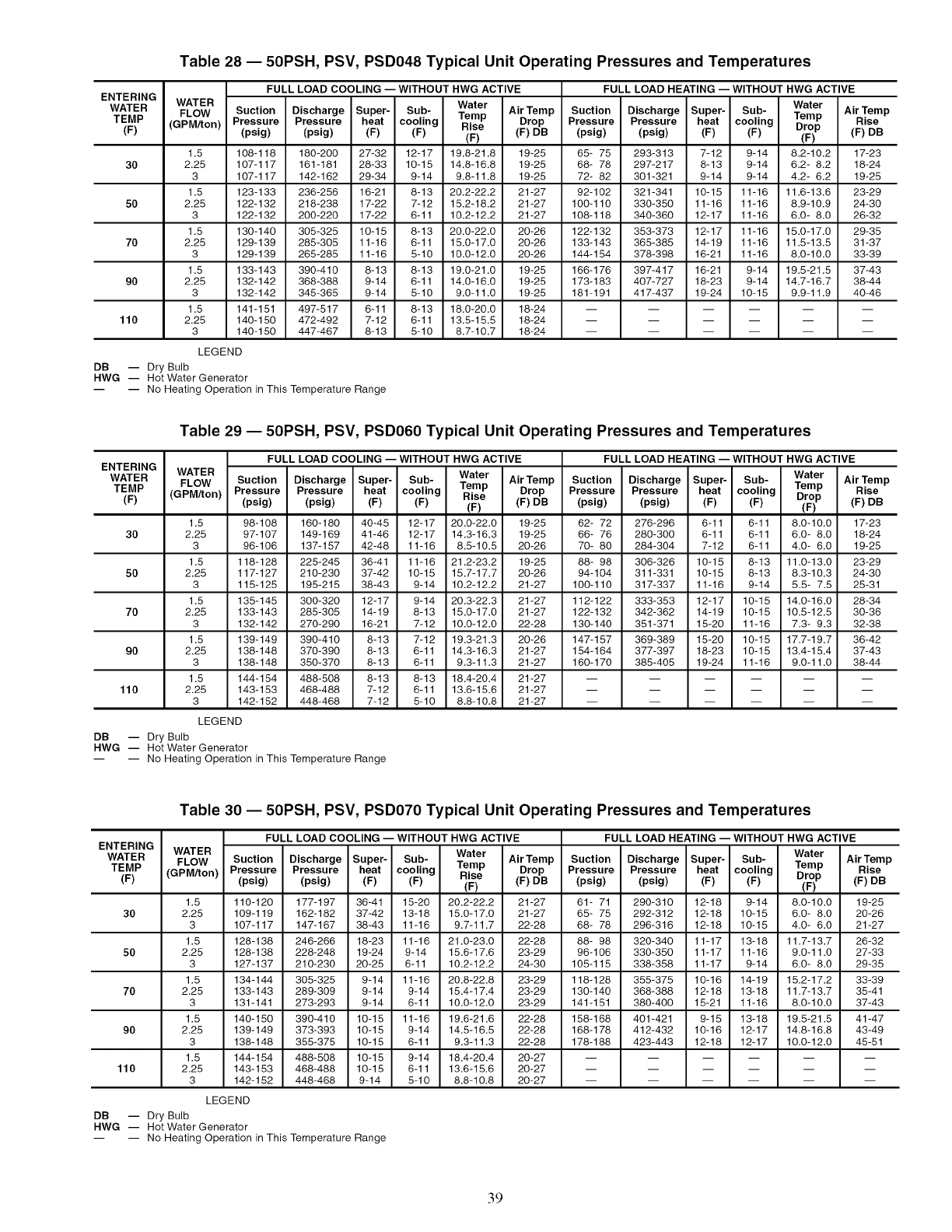
Table 28 -- 50PSH, PSV, PSD048 Typical Unit Operating Pressures and Temperatures
ENTERING
WATER
TEMP
(F)
1.5
30 2.25
3
1.5
50 2.25
3
1.5
70 2.25
3
1.5
90 2.25
3
1.5
110 2.25
3
FULL LOAD COOLING -- WITHOUT HWG ACTIVE FULL LOAD HEATING -- WITHOUT HWG ACTIVE
WATER Water Water
FLOW Suction Discharge Super- Sub- Temp Air Temp Suction Discharge Super- Sub- Temp Air Temp
(GPM/ton) Pressure Pressure heat cooling Rise
Rise Drop Pressure Pressure heat cooling Drop (F) DB
(psig) (psig) (F) (F) (F) (F) DB (psig) (psig) (F) (F) (F)
108-118 180-200 27-32 12-17 19.8-21.8 19-25 65- 75 293-313 7-12 9-14 8.2-10.2 17-23
107-117 161-181 28-33 10-15 14.8-16.8 19-25 68- 78 297-217 8-13 9-14 6.2- 8.2 18-24
107-117 142-162 29-34 9-14 9.8-11.8 19-25 72- 82 301-321 9-14 9-14 4.2- 6.2 19-25
123-133 236-256 16-21 8-13 20.2-22.2 21-27 92-102 321-341 10-15 11-16 11.6-13.6 23-29
122-132 218-238 17-22 7-12 15.2-18.2 21-27 100-110 330-350 11-16 11-16 8.9-10.9 24-30
122-132 200-220 17-22 6-11 10.2-12.2 21-27 108-118 340-360 12-17 11-16 6.0- 8.0 26-32
130-140 305-325 10-15 8-13 20.0-22.0 20-26 122-132 353-373 12-17 11-16 15.0-17.0 29-35
129-139 285-305 11-16 6-11 15.0-17.0 20-26 133-143 365-385 14-19 11-16 11.5-13.5 31-37
129-139 265-285 11-16 5-10 10.0-12.0 20-26 144-154 378-398 16-21 11-16 8.0-10.0 33-39
133-143 390-410 8-13 8-13 19.0-21.0 19-25 166-176 397-417 16-21 9-14 19.5-21.5 37-43
132-142 368-388 9-14 6-11 14.0-16.0 19-25 173-183 407-727 18-23 9-14 14.7-16.7 38-44
132-142 345-365 9-14 5-10 9.0-11.0 19-25 181-191 417-437 19-24 10-15 9.9-11.9 40-46
141-151 497-517 6-11 8-13 18.0-20.0 18-24 ......
140-150 472-492 7-12 6-11 13.5-15.5 18-24 ......
140-150 447-467 8-13 5-10 8.7-10.7 18-24 ......
LEGEND
DB -- Dry Bulb
HWG -- Hot Water Generator
-- -- No Heating Operation in This Temperature Range
Table 29 -- 50PSH, PSV, PSD060 Typical Unit Operating Pressures and Temperatures
ENTERING
WATER
TEMP
(F)
1.5
30 2.25
3
1.5
50 2.25
3
1.5
70 2.25
3
1.5
90 2.25
3
1.5
110 2.25
3
FULL LOAD COOLING -- WITHOUT HWG ACTIVE FULL LOAD HEATING -- WITHOUT HWG ACTIVE
WATER Water Water
FLOW Suction Discharge Super- Sub- Air Temp Suction Discharge Super- Sub- Air Temp
(GPM/ton) Pressure Pressure heat cooling Temp Drop Pressure Pressure heat cooling Temp Rise
Rise Drop
(psig) (psig) (F) (F) (F) (F) DB (psig) (psig) (F) (F) (F) (F) DB
98-108 160-180 40-45 12-17 20.0-22.0 19-25 62- 72 276-296 6-11 6-11 8.0-10.0 17-23
97-107 149-169 41-46 12-17 14.3-16.3 19-25 66- 76 280-300 6-11 6-11 6.0- 8.0 18-24
96-106 137-157 42-48 11-16 8.5-10.5 20-26 70- 80 284-304 7-12 6-11 4.0- 6.0 19-25
118-128 225-245 36-41 11-16 21.2-23.2 19-25 88- 98 306-326 10-15 8-13 11.0-13.0 23-29
117-127 210-230 37-42 10-15 15.7-17.7 20-26 94-104 311-331 10-15 8-13 8.3-10.3 24-30
115-125 195-215 38-43 9-14 10.2-12.2 21-27 100-110 317-337 11-16 9-14 5.5- 7.5 25-31
135-145 300-320 12-17 9-14 20.3-22.3 21-27 112-122 333-353 12-17 10-15 14.0-16.0 28-34
133-143 285-305 14-19 8-13 15.0-17.0 21-27 122-132 342-362 14-19 10-15 10.5-12.5 30-36
132-142 270-290 16-21 7-12 10.0-12.0 22-28 130-140 351-371 15-20 11-16 7.3- 9.3 32-38
139-149 390-410 8-13 7-12 19.3-21.3 20-26 147-157 369-389 15-20 10-15 17.7-19.7 36-42
138-148 370-390 8-13 6-11 14.3-16.3 21-27 154-164 377-397 18-23 10-15 13.4-15.4 37-43
138-148 350-370 8-13 6-11 9.3-11.3 21-27 160-170 385-405 19-24 11-16 9.0-11.0 38-44
144-154 488-508 8-13 8-13 18.4-20.4 21-27 ......
143-153 468-488 7-12 6-11 13.6-15.6 21-27 ......
142-152 448-468 7-12 5-10 8.8-10.8 21-27 ......
LEGEND
DB -- Dry Bulb
HWG -- Hot Water Generator
-- -- No Heating Operation in This Temperature Range
Table 30 -- 50PSH, PSV, PSD070 Typical Unit Operating Pressures and Temperatures
ENTERING
WATER
TEMP
(F)
1.5
30 2.25
3
1.5
50 2.25
3
1.5
70 2.25
3
1.5
90 2.25
3
1.5
110 2.25
3
FULL LOAD COOLING -- WITHOUT HWG ACTIVE FULL LOAD HEATING -- WITHOUT HWG ACTIVE
WATER Water Water
FLOW Suction Discharge Super- Sub- AirTemp Suction Discharge Super- Sub- AirTemp
(GPM/ton) Pressure Pressure heat cooling Temp Drop Pressure Pressure heat cooling Temp Rise
Rise Drop
(psig) (psig) (F) (F) (F) (F) DB (psig) (psig) (F) (F) (F) (F) DB
110-120 177-197 36-41 15-20 20.2-22.2 21-27 61- 71 290-310 12-18 9-14 8.0-10.0 19-25
109-119 162-182 37-42 13-18 15.0-17.0 21-27 65- 75 292-312 12-18 10-15 6.0- 8.0 20-26
107-117 147-167 38-43 11-16 9.7-11.7 22-28 68- 78 296-316 12-18 10-15 4.0- 6.0 21-27
128-138 246-266 18-23 11-16 21.0-23.0 22-28 88- 98 320-340 11-17 13-18 11.7-13.7 26-32
128-138 228-248 19-24 9-14 15.6-17.6 23-29 96-106 330-350 11-17 11-16 9.0-11.0 27-33
127-137 210-230 20-25 6-11 10.2-12.2 24-30 105-115 338-358 11-17 9-14 6.0- 8.0 29-35
134-144 305-325 9-14 11-16 20.8-22.8 23-29 118-128 355-375 10-16 14-19 15.2-17.2 33-39
133-143 289-309 9-14 9-14 15.4-17.4 23-29 130-140 368-388 12-18 13-18 11.7-13.7 35-41
131-141 273-293 9-14 6-11 10.0-12.0 23-29 141-151 380-400 15-21 11-16 8.0-10.0 37-43
140-150 390-410 10-15 11-16 19.6-21.6 22-28 158-168 401-421 9-15 13-18 19.5-21.5 41-47
139-149 373-393 10-15 9-14 14.5-16.5 22-28 168-178 412-432 10-16 12-17 14.8-16.8 43-49
138-148 355-375 10-15 6-11 9.3-11.3 22-28 178-188 423-443 12-18 12-17 10.0-12.0 45-51
144-154 488-508 10-15 9-14 18.4-20.4 20-27 ......
143-153 468-488 10-15 6-11 13.6-15.6 20-27 ......
142-152 448-468 9-14 5-10 8.8-10.8 20-27 ......
LEGEND
DB -- Dry Bulb
HWG -- Hot Water Generator
-- -- No Heating Operation in This Temperature Range
39
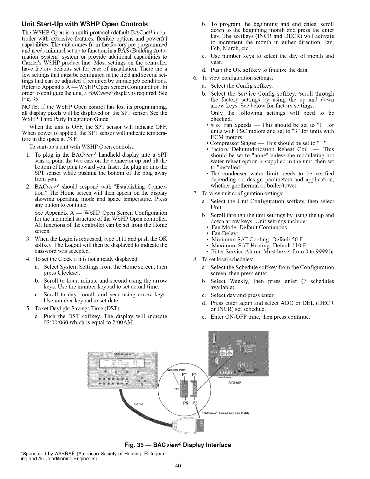
Unit Start-Up with WSHP Open Controls
The WSHP Open is a multi-protocol (default BACnet*) con-
troller with extensive features, flexible options and powerful
capabilities. The unit comes from the factory pre-programmed
and needs minimal set up to function in a BAS (Building Auto-
mation System) system or provide additional capabilities to
Carrier's WSHP product line. Most settings on the controller
have factory defaults set for ease of installation. There are a
few settings that must be configured in the field and several set-
tings that can be adjusted if required by unique job conditions.
Refer to Appendix A -- WSHP Open Screen Configuration. In
order to configure the unit, a BACvie_ display is required. See
Fig. 35.
NOTE: If the WSHP Open control has lost its programming,
all display pixels will be displayed on the SPY sensor. See the
WSHP Third Party Integration Guide.
When the unit is OFF, the SPY sensor will indicate OFF.
When power is applied, the SPY sensor will indicate tempera-
rare in the space at 78 E
To start-up a unit with WSHP Open controls:
1. To plug in the BACvieu_' handheld display into a SPY
sensor, point the two ears on the connector up and tilt the
bottom of the plug toward you. Insert the plug up into the
SPY sensor while pushing the bottom of the plug away
from you.
2. BACview 6 should respond with "Establishing Connec-
tion." The Home screen will then appear on the display
showing operating mode and space temperature. Press
any button to continue.
See Appendix A -- WSHP Open Screen Configuration
for the hierarchal structure of the WSHP Open controller.
All functions of the controller can be set from the Home
screen.
3. When the Login is requested, type 1111 and push the OK
softkey. The Logout will then be displayed to indicate the
password was accepted.
4. To set the Clock if it is not already displayed:
a. Select System Settings from the Home screen, then
press Clockset.
b. Scroll to hour, minute and second using the arrow
keys. Use the number keypad to set actual time.
c. Scroll to day, month and year using arrow keys.
Use number keypad to set date.
5. To set Daylight Savings Time (DST):
a. Push the DST softkey. The display will indicate
02:00:060 which is equal to 2:00AM.
b. To program the beginning and end dates, scroll
down to the beginning month and press the enter
key. The softkeys (INCR and DECR) will activate
to increment the month in either direction, Jan,
Feb, March, etc.
c. Use number keys to select the day of month and
year.
d. Push the OK softkey to finalize the data.
6. To view configuration settings:
a. Select the Config softkey.
b. Select the Service Config softkey. Scroll through
the factory settings by using the up and down
arrow keys. See below for factory settings.
Only the following settings will need to be
checked.
• # of Fan Speeds -- This should be set to "1" for
units with PSC motors and set to "3" for units with
ECM motors.
• Compressor Stages -- This should be set to "1."
• Factory Dehumidification Reheat Coil -- This
should be set to "none" unless the modulating hot
water reheat option is supplied in the unit, then set
to "installed."
• The condenser water limit needs to be verified
depending on design parameters and application,
whether geothermal or boiler/tower.
7. To view unit configuration settings:
a. Select the Unit Configuration softkey, then select
Unit.
b.
8.
Scroll through the unit settings by using the up and
down arrow keys. Unit settings include:
• Fan Mode: Default Continuous
• Fan Delay:
• Minimum SAT Cooling: Default 50 F
• Maximum SAT Heating: Default 110 F
• Filter Service Alarm: Must be set from 0 to 9999 hr
set local schedules:To
a. Select the Schedule softkey from the Configuration
screen, then press enter.
b. Select Weekly, then press enter (7 schedules
available).
c. Select day and press enter.
d. Press enter again and select ADD or DEL (DECR
or INCR) set schedule.
e. Enter ON/OFF time, then press continue.
Fig. 35 -- BACvievv sDisplay Interface
*Sponsored by ASHRAE (AmericanSociety of Heating, Refrigerat-
ingand AirConditioning Engineers).
40
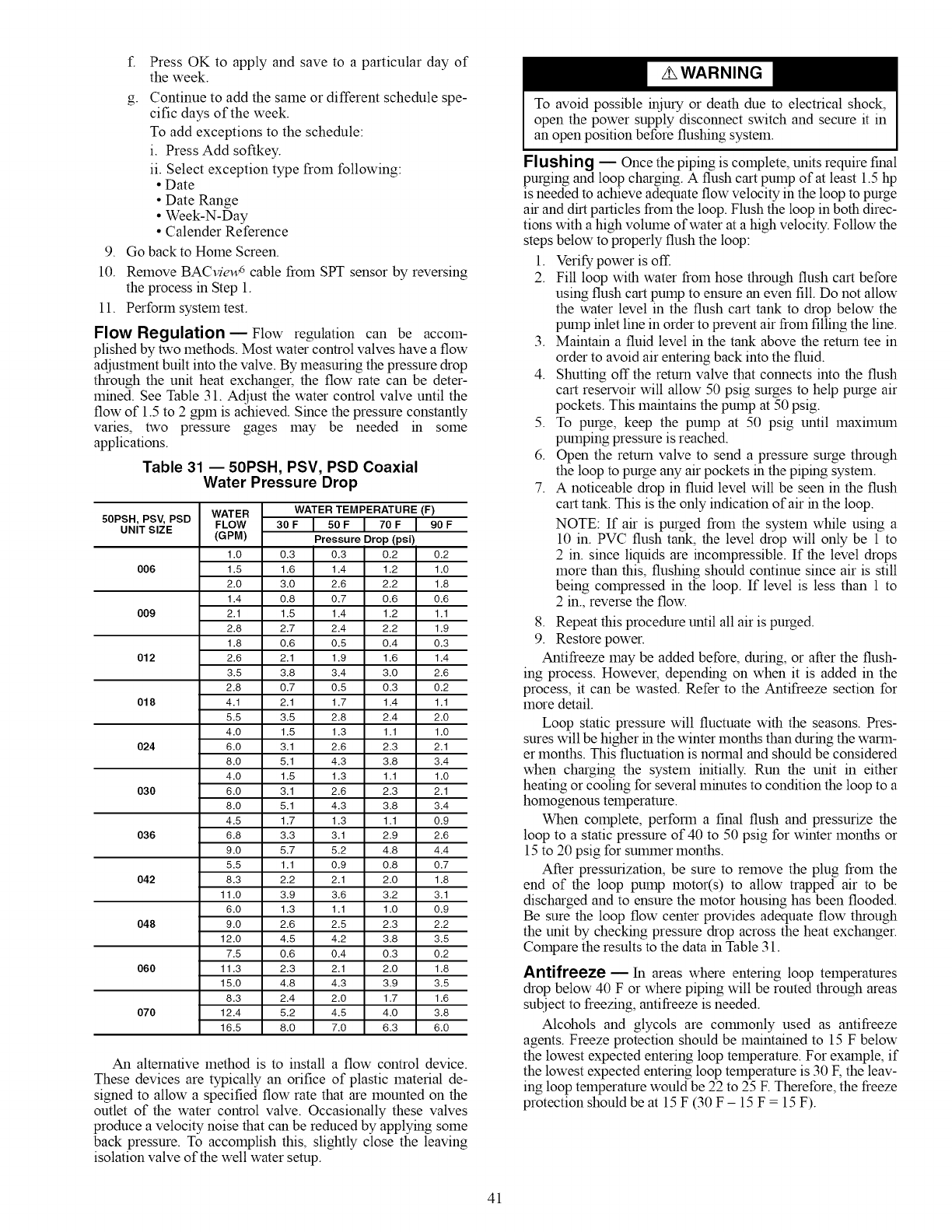
9.
10.
f. Press OK to apply and save to a particular day of
the week.
g- Continue to add the same or different schedule spe-
cific days of the week.
To add exceptions to the schedule:
i. Press Add softkey.
ii. Select exception type from following:
• Date
• Date Range
• Week-N-Day
• Calender Reference
Go back to Home Screen.
Remove BACvieu_ cable from SPT sensor by reversing
the process in Step 1.
11. Perform system test.
Flow Regulation E Flow regulation can be accom-
plished by two methods. Most water control valves have a flow
adjustment built into the valve. By measuring the pressure drop
through the unit heat exchanger, the flow rate can be deter-
mined. See Table 31. Adjust the water control valve until the
flow of 1.5 to 2gpm is achieved. Since the pressure constantly
varies, two pressure gages may be needed in some
applications.
Table 31 -- 50PSH, PSV, PSD Coaxial
Water Pressure Drop
50PSH, PS_ PSD WATER WATER TEMPERATURE (F)
UNIT SIZE FLOW 3OF IS0F I 70F I 90F
(GPM) Pressure Drop (psi)
1.0 0.3 0.3 0.2 0.2
006 1.5 1.6 1.4 1.2 1.0
2.0 3.0 2.6 2.2 1.8
1.4 0.8 0.7 0.6 0.6
009 2.1 1.5 1.4 1.2 1.1
2.8 2.7 2.4 2.2 1.9
1.8 0.6 0.5 0.4 0.3
012 2.6 2.1 1.9 1.6 1.4
3.5 3.8 3.4 3.0 2.6
2.8 0.7 0.5 0.3 0.2
018 4.1 2.1 1.7 1.4 1.1
5.5 3.5 2.8 2.4 2.0
4.0 1.5 1.3 1.1 1.0
024 6.0 3.1 2.6 2.3 2.1
8.0 5.1 4.3 3.8 3.4
4.0 1.5 1.3 1.1 1.0
030 6.0 3.1 2.6 2.3 2.1
8.0 5.1 4.3 3.8 3.4
4.5 1.7 1.3 1.1 0.9
036 6.8 3.3 3.1 2.9 2.6
9.0 5.7 5.2 4.8 4.4
5.5 1.1 0.9 0.8 0.7
042 8.3 2.2 2.1 2.0 1.8
11.0 3.9 3.6 3.2 3.1
6.0 1.3 1.1 1.0 0.9
048 9.0 2.6 2.5 2.3 2.2
12.0 4.5 4.2 3.8 3.5
7.5 0.6 0.4 0.3 0.2
060 11.3 2.3 2.1 2.0 1.8
15.0 4.8 4.3 3.9 3.5
8.3 2.4 2.0 1.7 1.6
070 12.4 5.2 4.5 4.0 3.8
16.5 8.0 7.0 6.3 6.0
An alternative method is to install a flow control device.
These devices are typically an orifice of plastic material de-
signed to allow a specified flow rate that are mounted on the
outlet of the water control valve. Occasionally these valves
produce a velocity noise that can be reduced by applying some
back pressure. To accomplish this, slightly close the leaving
isolation valve of the well water setup.
To avoid possible injury or death due to electrical shock,
open the power supply disconnect switch and secure it in
an open position before flushing system.
FIu sh ing EOnce the piping is complete, units require final
purging and loop charging. A flush cart pump of at least 1.5 hp
is needed to achieve adequate flow velocity in the loop to purge
air and dirt particles from the loop. Flush the loop in both direc-
tions with a high volume of water at a high velocity. Follow the
steps below to properly flush the loop:
1. Verify power is off.
2. Fill loop with water from hose through flush cart before
using flush cart pump to ensure an even fill. Do not allow
the water level in the flush cart tank to drop below the
pump inlet line in order to prevent air from filling the line.
3. Maintain a fluid level in the tank above the return tee in
order to avoid air entering back into the fluid.
4. Shutting off the return valve that connects into the flush
cart reservoir will allow 50 psig surges to help purge air
pockets. This maintains the pump at 50 psig.
5. To purge, keep the pump at 50 psig until maximum
pumping pressure is reached.
6. Open the return valve to send a pressure surge through
the loop to purge any air pockets in the piping system.
7. A noticeable drop in fluid level will be seen in the flush
cart tank. This is the only indication of air in the loop.
NOTE: If air is purged from the system while using a
10 in. PVC flush tank, the level drop will only be 1 to
2 in. since liquids are incompressible. If the level drops
more than this, flushing should continue since air is still
being compressed in the loop. If level is less than 1 to
2 in., reverse the flow.
8. Repeat this procedure until all air is purged.
9. Restore power.
Antifreeze may be added before, during, or after the flush-
ing process. However, depending on when it is added in the
process, it can be wasted. Refer to the Antifreeze section for
more detail.
Loop static pressure will fluctuate with the seasons. Pres-
sures will be higher in the winter months than during the warm-
er months. This fluctuation is normal and should be considered
when charging the system initially. Run the unit in either
heating or cooling for several minutes to condition the loop to a
homogenous temperature.
When complete, perform a final flush and pressurize the
loop to a static pressure of 40 to 50 psig for winter months or
15 to 20 psig for smmner months.
After pressurization, be sure to remove the plug from the
end of the loop pump motor(s) to allow trapped air to be
discharged and to ensure the motor housing has been flooded.
Be sure the loop flow center provides adequate flow through
the unit by checking pressure drop across the heat exchanger.
Compare the results to the data in Table 31.
Antifreeze- In areas where entering loop temperatures
drop below 40 F or where piping will be routed through areas
subject to freezing, antifreeze is needed.
Alcohols and glycols are colranonly used as antifreeze
agents. Freeze protection should be maintained to 15 F below
the lowest expected entering loop temperature. For example, if
the lowest expected entering loop temperature is 30 F, the leav-
ing loop temperature would be 22 to 25 E Therefore, the freeze
protection should be at 15 F (30 F - 15 F = 15 F).
41
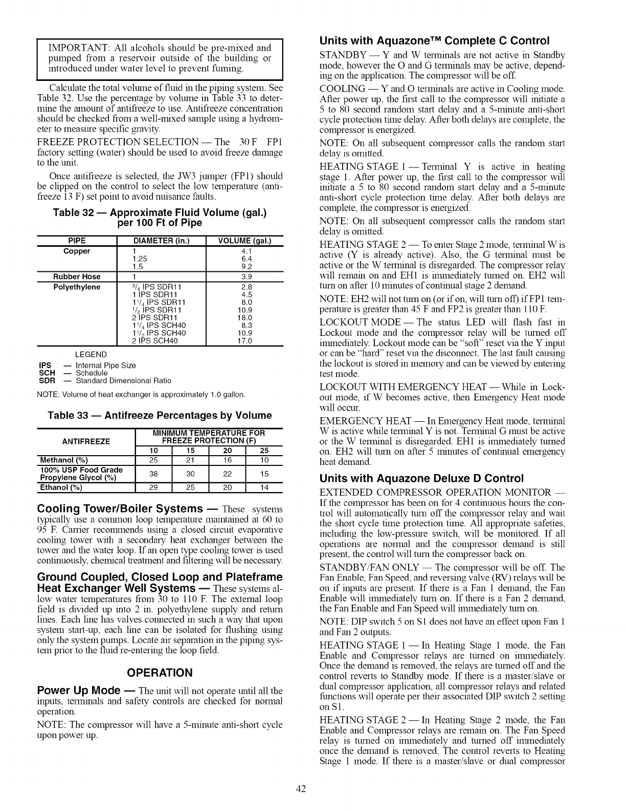
IMPORTANT:All alcoholsshouldbepre-mixedand
pumpedfromareservoiroutsideof thebuildingor
introducedunderwaterleveltopreventfuming.
Calculatethetotalvolumeoffluidinthepipingsystem.See
Table32.UsethepercentagebyvolumeinTable33todeter-
minetheamountofantifreezetouse.Antifreezeconcentration
shouldbecheckedfromawell-mixedsampleusingahydrom-
etertomeasurespecificgravity.
FREEZEPROTECTIONSELECTION-- The 30F FP1
factorysetting(water)shouldbeusedtoavoidfreezedamage
totheunit.
Onceantifreezeisselected,theJW3jumper(FP1)should
beclippedonthecontroltoselectthelowtemperature(anti-
freeze13F)setpointtoavoidnuisancefaults.
Table 32 -- Approximate Fluid Volume (gal.)
per 100 Ft of Pipe
PIPE DIAMETER (in.)
Copper
Rubber Hose
Polyethylene
1
1.25
1.5
1
3/4 IPS SDR11
1 IPS SDR11
11/4 IPS SDR11
1/2 IPS SDR11
2 IPS SDR11
11/4 IPS SCH40
11/2 IPS SCH40
2 IPS SCH40
VOLUME (gal.)
4.1
6.4
9.2
3.9
2.8
4.5
8.0
10.9
18.0
8.3
10.9
17.0
LEGEND
IPS -- Internal Pipe Size
SCH -- Schedule
SDR -- Standard Dimensional Ratio
NOTE: Volume of heat exchanger is approximately 1.0 gallon.
Table 33 -- Antifreeze Percentages by Volume
ANTIFREEZE
Methanol (%)
100% USP Food Grade
Propylene Glycol (%)
Ethanol (%)
MINIMUM TEMPERATURE FOR
FREEZE PROTECTION (F)
10 15 20 25
25 21 16 10
38 30 22 15
29 25 20 14
Cooling Tower/Boiler Systems -- These systems
typically use a common loop temperature maintained at 60 to
95 F. Carrier recommends using a closed circuit evaporative
cooling tower with a secondary heat exchanger between the
tower and the water loop. If an open type cooling tower is used
continuously, chemical treatment and filtering will be necessary.
Ground Coupled, Closed Loop and Plateframe
Heat Exchanger Well Systems -- Thesesystemsal-
low water temperatures from 30 to ll0 F. The external loop
field is divided up into 2 in. polyethylene supply and return
lines. Each line has valves connected in such a way that upon
system start-up, each line can be isolated for flushing using
only the system pumps. Locate air separation in the piping sys-
tem prior to the fluid re-entering the loop field.
OPERATION
Power Up Mode _ The unit will not operate until all the
inputs, terminals and safety controls are checked for normal
operation.
NOTE: The compressor will have a 5-minute anti-short cycle
upon power up.
Units with Aquazone TM Complete C Control
STANDBY- Y and W terminals are not active in Standby
mode, however the O and G terminals may be active, depend-
ing on the application. The compressor will be off.
COOLING -- Y and O terminals are active in Cooling mode.
After power up, the first call to the compressor will initiate a
5 to 80 second random start delay and a 5-minute anti-short
cycle protection time delay. After both delays are complete, the
compressor is energized.
NOTE: On all subsequent compressor calls the random start
delay is omitted.
HEATING STAGE 1--Terminal Y is active in heating
stage 1. After power up, the first call to the compressor will
initiate a 5 to 80 second random start delay and a 5-minute
anti-short cycle protection time delay. After both delays are
complete, the compressor is energized.
NOTE: On all subsequent compressor calls the random start
delay is omitted.
HEATING STAGE 2 -- To enter Stage 2 mode, terminal W is
active (Y is already active). Also, the G terminal must be
active or the W terminal is disregarded. The compressor relay
will remain on and EH1 is ilmnediately turned on. EH2 will
turn on after 10 minutes of continual stage 2 demand.
NOTE: EH2 will not turn on (or if on, will turn ot_ ifFP1 tem-
perature is greater than 45 F and FP2 is greater than 110 E
LOCKOUT MODE- The status LED will flash fast in
Lockout mode and the compressor relay will be turned off
immediately. Lockout mode can be "soft" reset via the Y input
or can be "hard" reset via the disconnect. The last fault causing
the lockout is stored in memory and can be viewed by entering
test mode.
LOCKOUT WITH EMERGENCY HEAT -- While in Lock-
out mode, if W becomes active, then Emergency Heat mode
will occur.
EMERGENCY HEAT -- In Emergency Heat mode, terminal
W is active while terminal Y is not. Terminal G must be active
or the W terminal is disregarded. EH1 is ilmnediately turned
on. EH2 will turn on after 5 minutes of continual emergency
heat demand.
Units with Aquazone Deluxe D Control
EXTENDED COMPRESSOR OPERATION MONITOR --
If the compressor has been on for 4 continuous hours the con-
trol will automatically turn off the compressor relay and wait
the short cycle time protection time. All appropriate safeties,
including the low-pressure switch, will be monitored. If all
operations are normal and the compressor demand is still
present, the control will turn the compressor back on.
STANDBY/FAN ONLY -- The compressor will be off. The
Fan Enable, Fan Speed, and reversing valve (RV) relays will be
on if inputs are present. If there is a Fan 1 demand, the Fan
Enable will ilmnediately turn on. If there is a Fan 2 demand,
the Fan Enable and Fan Speed will hmnediately turn on.
NOTE: DIP switch 5 on S1 does not have an effect upon Fan 1
and Fan 2 outputs.
HEATING STAGE 1 -- In Heating Stage 1 mode, the Fan
Enable and Compressor relays are turned on ilmnediately.
Once the demand is removed, the relays are turned off and the
control reverts to Standby mode. If there is a master/slave or
dual compressor application, all compressor relays and related
functions will operate per their associated DIP switch 2 setting
on S1.
HEATING STAGE 2- In Heating Stage 2 mode, the Fan
Enable and Compressor relays are remain on. The Fan Speed
relay is turned on ilmnediately and turned off immediately
once the demand is removed. The control reverts to Heating
Stage 1 mode. If there is a master/slave or dual compressor
42
application,allcompressorrelaysandrelatedfunctionswill
operatepertheirassociatedDIPswitch2settingonS1.
HEATINGSTAGE3- In HeatingStage3 mode,theFan
Enable,FanSpeedandCompressorrelaysremainon.TheEH1
outputisturnedonhmnediately.WithcontinuingHeatStage3
demand,EH2willturnonafter10minutes.EH1andEH2are
turnedoffilranediatelywhentheHeatingStage3demandisre-
moved.ThecontrolrevertstoHeatingStage2mode.
TheoutputsignalEH2willbeoffifFP1isgreaterthan45F
ANDFP2(whenshorted)isgreaterthan110FduringHeating
Stage3 mode.This conditionwill havea 30-second
recognitiontime.Also,duringHeatingStage3 mode,EH1,
EH2,FanEnable,andFanSpeedwillbeONif Ginputisnot
active.
EMERGENCYHEAT-- InEmergencyHeatmode,theFan
EnableandFanSpeedrelaysareturnedon.TheEH1outputis
turnedonilmnediately.WithcontinuingEmergencyHeatde-
man&EH2willturnonafter5minutes.FanEnableandFan
Speedrelaysareturnedoffaftera60-seconddelay.Thecontrol
revertstoStandbymode.
OutputEH1,EH2,FanEnable,andFanSpeedwillbeONif
theGinputisnotactiveduringEmergencyHeatmode.
COOLINGSTAGE1-- In CoolingStage1mode,theFan
Enable,compressorandRVrelaysareturnedonilranediately.
If configuredasstage2(DIPswitchsettoOFF)thenthecom-
pressorandfanwillnotturnonuntilthereisastage2demand.
The Fan Enable and compressor relays are turned off ilranedi-
ately when the Cooling Stage 1 demand is removed. The con-
trol reverts to Standby mode. The RV relay remains on until
there is a heating demand. If there is a master/slave or dual
compressor application, all compressor relays and related func-
tions will track with their associated DIP switch 2 on S1.
COOLING STAGE 2- In Cooling Stage 2 mode, the Fan
Enable, compressor and RV relays remain on. The Fan Speed
relay is turned on ilranediately and turned off ilmnediately
once the Cooling Stage 2 demand is removed. The control
reverts to Cooling Stage 1 mode. If there is a master/slave or
dual compressor application, all compressor relays and related
functions will track with their associated DIP switch 2 on S1.
NIGHT LOW LIMIT (NLL) STAGED HEAT1NG -- In NLL
staged Heating mode, the override (OVR) input becomes ac-
tive and is recognized as a call for heating and the control will
ilranediately go into a Heating Stage 1 mode. With an addition-
al 30 minutes of NLL demand, the control will go into Heating
Stage 2 mode. With another additional 30 minutes of NLL
demand, the control will go into Heating Stage 3 mode.
Units with HWR Option
FAN ONLY--A (G) call from the thermostat to the (G)
terminal of the Deluxe D control board will bring the unit
on in fan only mode.
COOLING STAGE 1--A simultaneous call from (G),
(Y1), and (O) to the (G), (Y1), (O/W2) terminals of the
Deluxe D control board will bring the unit on in Cooling
Stage 1.
COOLING STAGE2--A simultaneous call from (G),
(Y1), (Y2), and (O) to the (G), (Y1), (Y2), and (O/W2) ter-
minals of the Deluxe D control board will bring the unit on
in Cooling Stage 2. When the call is satisfied at the thermo-
stat the unit will continue to mn in Cooling Stage 1 until the
Cooling Stage 1 call is removed or satisfied, shutting down
the unit.
NOTE: Not all units have two-stage cooling functionality.
HEAT1NG STAGE 1--A simultaneous call from (G) and
(Y1) to the (G) and (Y1) terminals of the Deluxe D control
board will bring the unit on in Heating Stage 1.
HEAT1NG STAGE 2 --A simultaneous call from (G), (Y1),
and (Y2) to the (G), (Y1), and (Y2) terminals of the Deluxe
D control board will bring the unit on in Heating Stage 2.
When the call is satisfied at the thermostat the unit will con-
tinue to run in Heating Stage 1 until the call is removed or
satisfied, shutting down the unit.
NOTE: Not all units have two-stage heating functionality.
REHEAT MODE -- A call from the humidistat/dehumidis-
tat to the (H) terminal of the Deluxe D control board will
bring the unit on in Reheat mode if there is no call for cool-
ing at the thermostat. When the humidistat/dehumidistat call
is removed or satisfied the unit will shut down.
NOTE: Cooling always overrides Reheat mode. In the
Cooling mode, the unit cools and dehumidifies. If the cool-
ing thermostat is satisfied but there is still a call for dehu-
midification, the unit will continue to operate in Reheat
mode.
Units with WSHP Open Multiple Protocol E
The WSHP Open multi-protocol controller will control me-
chanical cooling, heating and waterside economizer outputs
based on its own space temperature input and set points. An
optional CO2 IAQ (indoor air quality) sensor mounted in the
space can maximize the occupant comfort. The WSHP Open
controller has its own hardware clock that is automatically set
when the heat pump software is downloaded to the board. Oc-
cupancy types are described in the scheduling section below.
The following sections describe the functionality of the WSHP
Open multi-protocol controller. All point objects referred to in
this sequence of operation will be referenced to the objects as
viewed in the BACview 6handheld user interface.
SCHEDULING- Scheduling is used to start!stop the unit
based on a time period to control the space temperature to spec-
ified occupied heating and cooling set points. The controller is
defaulted to control by occupied set points all the time, until ei-
ther a time schedule is configured with BACview 6, Field Assis-
tant, i-Vu _R:Open, or a third party control system to enable/dis-
able the BAS (Building Automation System) on!offpoint. The
local time and date must be set for these functions to operate
properly. The occupancy source can be changed to one of the
following:
Occupancy Schedules -- The controller will be occupied 24/7
until a time schedule has been configured using either Field
Assistant, i-Vu Open, BACview 6or a third party control system
to enable/disable the BAS on!off point. The BAS point can be
disabled by going to Config, then Unit, then Occupancy Sched-
ules and changing the point from enable to disable then click-
ing OK.
NOTE: This point must be enabled in order for the i-Vu Open,
Field Assistant, or BACview 6 control system to assign a time
schedule to the controller.
Schedule schedule -- The unit will operate according to the
schedule configured and stored in the unit. The schedule is
accessible via the BACview 6 Handheld tool, i-Vu Open, or
Field Assistant control system. The daily schedule consists of a
start/stop time (standard or 24-hour mode) and seven days of
the week, starting with Monday and ending on Sunday. To
enter a daily schedule, navigate to Config, then Sched, then
enter BACview 6 Admin Password (1111), then go to
schedule schedule. From here, enter either a Weekly or Excep-
tion schedule for the unit.
Occupancy Input Contact -- The WSHP Open controller has
the capability to use an external dry contact closure to deter-
mine the occupancy status of the unit. The Occupancy Sched-
ules will need to be disabled in order to utilize the occupancy
contact input.
NOTE: Scheduling can only be controlled from one source.
BAS (Building Automation System) On/Off -- A BAS
system that supports network scheduling can control the unit
through a network colmnunication and the BAS scheduling
function once the Occupancy Schedules have been disabled.
43
NOTE:Schedulingcaneitherbecontrolledviatheunitorthe
BAS,butnotboth.
INDOORFAN-- Theindoorfanwilloperateinanyoneof
threemodesdependingontheuserconfigurationselected.
FanmodecanbeselectedasAuto,Continuous,orAlways
On.InAutomode,thefanisinintermittentoperationduring
bothoccupiedandunoccupiedperiods.Continuousfanmode
isintermittentduringunoccupiedperiodsandcontinuousdur-
ingoccupiedperiods.AlwaysOnmodeoperatesthefancon-
tinuouslyduringbothoccupiedandunoccupiedperiods.Inthe
defaultmode,Continuous,thefanwillbeturnedonwhenever
anyoneofthefollowingistrue:
• Theunitisinoccupiedmodeasdeterminedbyitsoccu-
pancystatus.
• Thereisademandforcoolingorheatingintheunoccu-
piedmode.
• Thereisacallfordehumidification(optional).
Whenpowerisreappliedafterapoweroutage,therewillbe
aconfiguredtimedelayof5to600secondsbeforestartingthe
fan.TherearealsoconfiguredfandelaysforFanOnandFan
Off.TheFanOndelaydefinesthedelaytime(0to30seconds;
default10)beforethefanbeginsto operateafterheatingor
coolingis startedwhiletheFanOffdelaydefinesthedelay
time(0to180seconds;default45)thefanwillcontinuetoop-
erateafterheatingorcoolingisstopped.Thefanwillcontinue
torunaslongasthecompressors,heatingstages,orthedehu-
midificationrelaysareon.If theSPTfailurealarmorconden-
sateoverflowalarmisactive;thefanwillbeshutdownilrnne-
diatelyregardlessofoccupancystateordemand.
Automatic Fan Speed Control -- The WSHP Open controller
is capable of controlling up to three fan speeds using the ECM
(electronically colmnutated motor). The motor will operate at
the lowest speed possible to provide quiet and efficient fan op-
eration with the best latent capability. The motor will increase
speed if additional cooling or heating is required to obtain the
desired space temperature set point. The control increases the
motor's speed as the space temperature rises above the cooling
or below the heating set point. The amount of space tempera-
rare increase above or below the set point required to increase
the fan speed is user configurable in the set point. Also, the
control will increase the fan speed as the supply-air tempera-
rare approaches the configured minhnum or maximum limits.
Fan Speed Control (During Heating) -- Whenever heat is re-
quired and active, the control continuously monitors the sup-
ply-mr temperature to verify it does not rise above the config-
ured maximum heating SAT limit (110 F default). As the SAT
approaches this value, the control will increase the fan speed as
required to ensure the SAT will remain within the limit. This
feature provides the most quiet and efficient operation by oper-
ating the fan at the lowest speed possible.
Fan Speed Control (During Cooling) -- Whenever mechani-
cal cooling is required and active, the control continuously
monitors the supply-air temperature to verify it does not fall be-
low the configured minimum cooling SAT limit (50 F default).
As the SAT approaches this value, the control will increase the
fan speed as required to ensure the SAT will remain within the
limit. The fan will operate at lowest speed to maximize latent
capacity during cooling.
COOLING -- The WSHP Open controller will operate one or
two stages of compression to maintain the desired cooling set
point. The compressor outputs are controlled by the PI (propor-
tional-integral) cooling loop and cooling stages capacity algo-
rithin. They will be used to calculate the desired number of
stages needed to satisfy the space by comparing the space tem-
perature (SPT) to the appropriate cooling set point. The water
side economizer, if applicable, will be used for first stage cool-
ing in addition to the compressor(s). The following conditions
must be true in order for the cooling algorithin to run:
• Cooling is set to Enable.
• Heating mode is not active and the compressor time
guard has expired.
• Condensate overflow input is normal.
• If occupied, the SPT is greater than the occupied cooling
set point.
• Space temperature reading is valid.
• If unoccupied, the SPT is greater than the unoccupied
cooling set point.
• If economizer cooling is available and active and the
economizer alone is insufficient to provide enough cool-
ing.
• OAT (if available) is greater than the cooling lockout
temperature.
If all the above conditions are met, the compressors will be
energized as required, otherwise they will be deenergized. If
cooling is active and should the SAT approach the lninimum
SAT limit, the fan will be indexed to the next higher speed.
Should this be insufficient and if the SAT falls further (equal to
the minimum SAT lhnit), the fan will be indexed to the maxi-
mum speed. If the SAT continues to fall 5 c F below the mini-
1hum SAT lhnit, all cooling stages will be disabled.
During Cooling mode, the reversing valve output will be
held in the cooling position (either B or O type as configured)
even after the compressor is stopped. The valve will not switch
position until the Heating mode is required.
The configuration screens contain the minimum SAT
parameter as well as cooling lockout based on outdoor-air
temperature (OAT) Both can be adjusted to meet various
specifications.
There is a 5-minute offtime for the compressor as well as a
5-minute time delay when staging up to allow the SAT to
achieve a stable temperature before energizing a second stage
of capacity. Likewise, a 45-second delay is used when staging
down.
After a compressor is staged off, it may be restarted again
after a normal time-guard period of 5 minutes and if the sup-
ply-mr temperature has increased above the minimum supply-
air temperature limit.
The WSHP Open controller provides a status input to moni-
tor the compressor operation. The stares is monitored to deter-
mine if the compressor status matches the colrnnanded state.
This input is used to determine if a refrigerant safety switch or
other safety device has tripped and caused the compressor to
stop operating normally. If this should occur, an alarm will be
generated to indicate the faulted compressor condition.
HEATING -- The WSHP Open controller will operate one or
two stages of compression to maintain the desired heating set
point. The compressor outputs are controlled by the heating PI
(proportional-integral) loop and heating stages capacity algo-
rithin. They will be used to calculate the desired number of
stages needed to satisfy the space by comparing the space tem-
perature (SPT) to the appropriate heating set point. The follow-
ing conditions must be true in order for the heating algorithin to
run:
• Heating is set to Enable.
• Cooling mode is not active and the compressor time
guard has expired.
• Condensate overflow input is normal.
• If occupied, the SPT is less than the occupied heating set
point.
• Space temperature reading is valid.
• If unoccupied, the SPT is less than the unoccupied heat-
ing set point.
• OAT (if available) is less than the heating lockout
temperature.
If all the above conditions are met, the heating outputs will
be energized as required, otherwise they will be deenergized. If
the heating is active and should the SAT approach the maxi-
1hum SAT lhnit, the fan will be indexed to the next higher
44
speed.Shouldthisbeinsufficient,andtheSATrisesfurther
reachingthemaximumheatingSATlimit,thefanwill be
indexedtothemaxhnumspeed.If theSATstillcontinuesto
rise5cFabovethemaximumlimit,allheatingstageswillbe
disabled.
DuringHeatingmode,thereversingvalveoutputwill be
heldintheheatingposition(eitherBorOtypeasconfigured)
evenafterthecompressorisstopped.Thevalvewillnotswitch
positionuntiltheCoolingmodeisrequired.
TheconfigurationscreenscontainthemaximumSAT
parameteraswellasheatinglockoutbasedonoutdoor-air
temperature(OAT);bothcanbeadjustedto meetvarious
specifications.
Thereisa5-minuteoffthneforthecompressoraswellasa
5-minutetimedelaywhenstagingupto allowtheSATto
achieveastabletemperaturebeforeenergizingasecondstage
ofcapacity.Likewise,a45-seconddelayisusedwhenstaging
down.
After a compressor is staged off, it may be restarted again
after a normal time-guard period of 5 minutes and if the sup-
ply-mr temperature has fallen below the maximum supply air
temperature limit.
The WSHP Open controller provides a status input to moni-
tor the compressor operation. The stares is monitored to deter-
mine if the compressor status matches the colmnanded state.
This input is used to determine if a refrigerant safety switch or
other safety device has tripped and caused the compressor to
stop operating normally. If this should occur, an alarm will be
generated to indicate the faulted compressor condition. Also, if
auxiliary heat is available (see below), the auxiliary heat will
operate to replace the reverse cycle heating and maintain the
space temperature as required.
AUXILIARY HEAT -- The WSHP Open controller can con-
trol a two-position, modulating water, or steam valve connect-
ed to a coil on the discharge side of the unit and supplied by a
boiler or a single-stage ducted electric heater in order to main-
tain the desired heating set point. Should the compressor capac-
ity be insufficient or a compressor failure occurs, the auxiliary
heat will be used. Unless the compressor fails, the auxiliary
heat will only operate to supplement the heat provided by the
compressor if the space temperature falls more than one degree
below the desired heating set point (the amount is config-
urable). The heat will be controlled so the SAT will not exceed
the maximum heating SAT lhnit.
Auxiliary Modulating Hot Water/Steam Heating Reheat
-- The control can modulate a hot water or steam valve con-
nected to a coil on the discharge side of the unit and supplied
by a boiler in order to maintain the desired heating set point
should the compressor capacity be insufficient or a compressor
failure occurs. Unless a compressor fault condition exists, the
valve will only operate to supplement the heat provided by the
compressor if the space temperature falls more than one degree
below the desired heating set point. The valve will be con-
trolled so the SAT will not exceed the maximum heating SAT
limit.
Two-Position Hot Water/Steam Heating Reheat -- The con-
trol can operate a two-position, NO or NC, hot water or steam
valve connected to a coil on the discharge side of the unit and
supplied by a boiler in order to maintain the desired heating set
point should the compressor capacity be insufficient or a com-
pressor failure occurs. Unless a compressor fault condition ex-
ists, the valve will only open to supplement the heat provided
by the compressor if the space temperature falls more than one
degree below the desired heating set point. The valve will be
controlled so the SAT will not exceed the maximum heating
SAT lhnit. The heat stage will also be subject to a 2-minute
minimum OFF time to prevent excessive valve cycling.
Single Stage Electric Auxiliary_ Heat -- The control can op-
erate a field-installed single stage of electric heat installed on
the discharge side of the unit in order to maintain the desired
heating set point should the compressor capacity be insufficient
or a compressor failure occurs. Unless a compressor fault con-
dition exists, the heat stage will only operate to supplement the
heat provided by the compressor if the space temperature falls
more than one degree below the desired heating set point. The
heat stage will be controlled so the SAT will not exceed the
maximum heating SAT limit. The heat stage will also be sub-
ject to a 2-minute minimum OFF time to prevent excessive
cycling.
INDOOR AIR QUALITY (IAQ) AND DEMAND CON-
TROLLED VENTILATION (DCV) -- If the optional in-
door air quality sensor is installed, the WSHP Open controller
can maintain indoor air quality via a modulating OA damper
providing demand controlled ventilation. The control operates
the modulating OA damper during occupied periods. The con-
trol monitors the CO2 level and compares it to the configured
set points, adjusting the ventilation rate as required. The control
provides proportional ventilation to meet the requirements of
ASHRAE (American Society of Heating, Refrigerating and
Air Conditioning Engineers) specifications by providing a base
ventilation rate and then increasing the rate as the CO2 level in-
creases. The control will begin to proportionally increase venti-
lation when the CO 2level rises above the start ventilation set
point and will reach the full ventilation rate when the CO2 level
is at or above the maxhnum set point. A user-configurable min-
imum damper position ensures that proper base ventilation is
delivered when occupants are not present. The IAQ configura-
tions can be accessed through the configuration screen. The
following conditions must be true in order for this algorithn to
run:
• Damper control is configured for DCV.
• The unit is in an occupied mode.
• The IAQ sensor reading is greater than the DCV start
control set point.
The control has four user adjustable set points: DCV start
control set point, DCV maximum control set point, minimum
damper position, and DCV maximum damper position.
Two-Position OA Damper -- The control can be configured
to operate a ventilation damper in a two-position ventilation
mode to provide the minimum ventilation requirements during
occupied periods.
DEHUMIDIFCATION- The WSHP Open controller will
provide occupied and unoccupied dehumidification only on
units that are equipped with the modulating hot water reheat
(HWR) option. This function requires an accessory space rela-
tive humidity sensor. When using a relative humidity sensor to
control dehumidification during occupied or unoccupied times,
the dehumidification set points are used accordingly. When the
indoor relative humidity becomes greater than the dehumidifi-
cation set point, a dehumidification demand will be acknowl-
edged. Once acknowledged, the dehumidification output will
be energized, bringing on the supply fan (medium speed), me-
chanical cooling, and the integral hot water reheat coil. The
controls will engage Cooling mode and waste heat from the
compressor cooling cycle will be returned to the reheat coil si-
multaneously, meaning that the reversing valve is causing the
compressor to operate in the Cooling mode. During Cooling
mode, the unit cools, dehumidifies, and disables the HWR coil;
however, once the call for cooling has been satisfied and there
is still a call for dehumidification, the unit will continue to op-
erate using the Reheat mode and HWR coil.
WATERSIDE ECONOMIZER -- The WSHP Open control-
ler has the capability of providing modulating or two-position
water economizer operation (for a field-installed economizer
coil mounted to the entering air side of the unit and connected
to the condenser water loop) in order to provide free cooling
(or preheating) when water conditions are optimal. Water econ-
omizer settings can be accessed through the equipment status
45
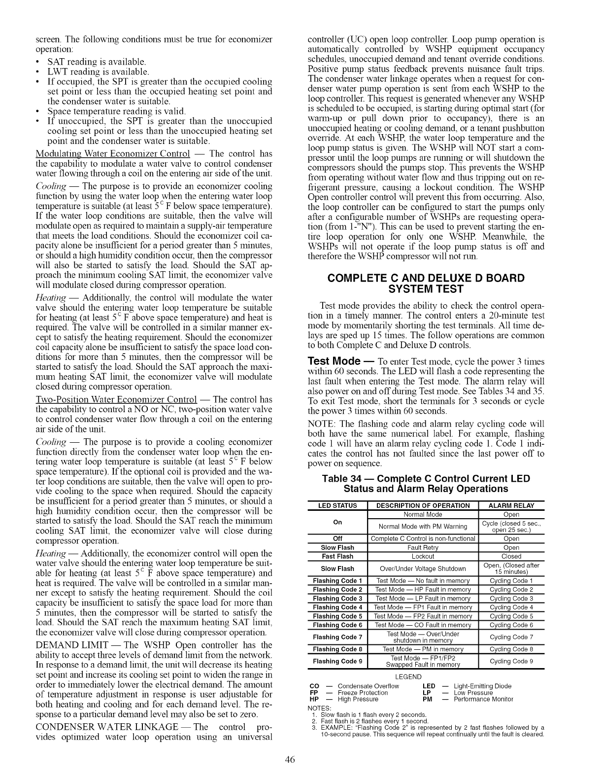
screen.Thefollowingconditionsmustbetrueforeconomizer
operation:
• SATreadingisavailable.
• LWTreadingisavailable.
• If occupied,theSPTisgreaterthantheoccupiedcooling
setpointorlessthantheoccupiedheatingsetpointand
thecondenserwaterissuitable.
• Spacetemperaturereadingisvalid.
• If unoccupied,theSPTis greaterthantheunoccupied
coolingsetpointorlessthantheunoccupiedheatingset
pointandthecondenserwaterissuitable.
Modulating Water Economizer Control -- The control has
the capability to modulate a water valve to control condenser
water flowing through a coil on the entering air side of the unit.
(_oling -- The purpose is to provide an economizer cooling
function by using the water loop when the entering water loop
temperature is suitable (at least 5 c F below space temperature).
If the water loop conditions are suitable, then the valve will
modulate open as required to maintain a supply-air temperature
that meets the load conditions. Should the economizer coil ca-
pacity alone be insufficient for a period greater than 5 minutes,
or should a high humidity condition occur, then the compressor
will also be started to satisfy the load. Should the SAT ap-
proach the minimum cooling SAT limit, the economizer valve
will modulate closed during compressor operation.
Heating- Additionally, the control will modulate the water
valve should the entering water loop temperature be suitable
for heating (at least 5c F above space temperature) and heat is
required. The valve will be controlled in a similar manner ex-
cept to satisfy the heating requirement. Should the economizer
coil capacity alone be insufficient to satisfy the space load con-
ditions for more than 5 minutes, then the compressor will be
started to satisfy the load. Should the SAT approach the maxi-
mum heating SAT lhnit, the economizer valve will modulate
closed during compressor operation.
Two-Position Water Economizer Control -- The control has
the capability to control a NO or NC, two-position water valve
to control condenser water flow through a coil on the entering
air side of the unit.
(_oling -- The purpose is to provide a cooling economizer
function directly from the condenser water loop when the en-
tering water loop temperature is suitable (at least 5c F below
space telnperature). If the optional coil is provided and the wa-
ter loop conditions are suitable, then the valve will open to pro-
vide cooling to the space when required. Should the capacity
be insufficient for a period greater than 5 minutes, or should a
high humidity condition occur, then the compressor will be
started to satisfy the load. Should the SAT reach the minimum
cooling SAT limit, the economizer valve will close during
compressor operation.
Heating -- Additionally, the economizer control will open the
water valve should the entering water loop temperature be suit-
able for heating (at least 5c F above space temperature) and
heat is required. The valve will be controlled in a similar man-
ner except to satisfy the heating requirement. Should the coil
capacity be insufficient to satisfy the space load for more than
5 minutes, then the compressor will be started to satisfy the
load. Should the SAT reach the maximum heating SAT limit,
the economizer valve will close during compressor operation.
DEMAND LIMIT- The WSHP Open controller has the
ability to accept three levels of demand lhnit from the network.
In response to a demand lhnit, the unit will decrease its heating
set point and increase its cooling set point to widen the range in
order to ilmnediately lower the electrical demand. The amount
of temperature adjustment in response is user adjustable for
both heating and cooling and for each demand level. The re-
sponse to a particular demand level may also be set to zero.
CONDENSER WATER LINKAGE -- The control pro-
vides optimized water loop operation using an universal
controller (UC) open loop controller. Loop pump operation is
automatically controlled by WSHP equipment occupancy
schedules, unoccupied demand and tenant override conditions.
Positive pump status feedback prevents nuisance fault trips.
The condenser water linkage operates when a request for con-
denser water pump operation is sent from each WSHP to the
loop controller. This request is generated whenever any WSHP
is scheduled to be occupied, is starting during optimal start (for
warm-up or pull down prior to occupancy), there is an
unoccupied heating or cooling demand, or a tenant pushbutton
ovemde. At each WSHR the water loop temperature and the
loop pump status is given. The WSHP will NOT start a com-
pressor until the loop pumps are running or will shutdown the
compressors should the pumps stop. This prevents the WSHP
from operating without water flow and thus tripping out on re-
frigerant pressure, causing a lockout condition. The WSHP
Open controller control will prevent this from occumng. Also,
the loop controller can be configured to start the pumps only
after a configurable number of WSHPs are requesting opera-
tion (from 1-"N"). This can be used to prevent starting the en-
tire loop operation for only one WSHR Meanwhile, the
WSHPs will not operate if the loop pump status is off and
therefore the WSHP compressor will not run.
COMPLETE C AND DELUXE D BOARD
SYSTEM TEST
Test mode provides the ability to check the control opera-
tion in a thnely manner. The control enters a 20-minute test
mode by momentarily shorting the test terminals. All time de-
lays are sped up 15 times. The follow operations are colmnon
to both Complete C and Deluxe D controls.
Test Mode -- To enter Test mode, cycle the power 3 times
within 60 seconds. The LED will flash a code representing the
last fault when entering the Test mode. The alarm relay will
also power on and offduring Test mode. See Tables 34 and 35.
To exit Test mode, short the terminals for 3 seconds or cycle
the power 3 times within 60 seconds.
NOTE: The flashing code and alarm relay cycling code will
both have the same numerical label. For example, flashing
code 1 will have an alarm relay cycling code 1. Code 1 indi-
cates the control has not faulted since the last power off to
power on sequence.
Table 34 -- Complete C Control Current LED
Status and Alarm Relay Operations
LED STATUS DESCRIPTION OF OPERATION
Normal Mode
On
off
Slow Flash
Fast Flash
Slow Flash
Flashing Code 1
Flashing Code 2
Flashing Code 3
Flashing Code 4
Flashing Code 5
Flashing Code 6
Flashing Code 7
Flashing Code 8
Flashing Code 9
Normal Mode with PM Warning
Complete C Control is non-functional
Fault Retry
Lockout
Over/Under Voltage Shutdown
Test Mode -- No fault in memory
Test Mode -- HP Fault in memory
Test Mode -- LP Fault in memory
Test Mode -- FP1 Fault in memory
Test Mode -- FP2 Fault in memory
Test Mode -- CO Fault in memory
Test Mode -- Over/Under
shutdown in memory
Test Mode -- PM in memory
Test Mode -- FP1/FP2
Swapped Fault in memory
LEGEND
ALARM RELAY
Open
Cycle (closed 5 sec,
open 25 sec.)
Open
Open
Closed
Open, (Closed after
15 minutes)
Cycling Code 1
Cycling Code 2
Cycling Code 3
Cycling Code 4
Cycling Code 5
Cycling Code 6
Cycling Code 7
Cycling Code 8
Cycling Code 9
CO -- Condensate Overflow LED -- Light-Emitting Diode
FP -- Freeze Protection LP -- Low Pressure
HP -- High Pressure PM -- Performance Monitor
NOTES:
1. Slow flash is 1 flash every 2 seconds.
2. Fast flash is 2 flashes every 1 second.
3. EXAMPLE: "Flashing Code 2" is represented by 2 fast flashes followed by a
10-second pause. This sequence will repeat continually until the fault is cleared.
46
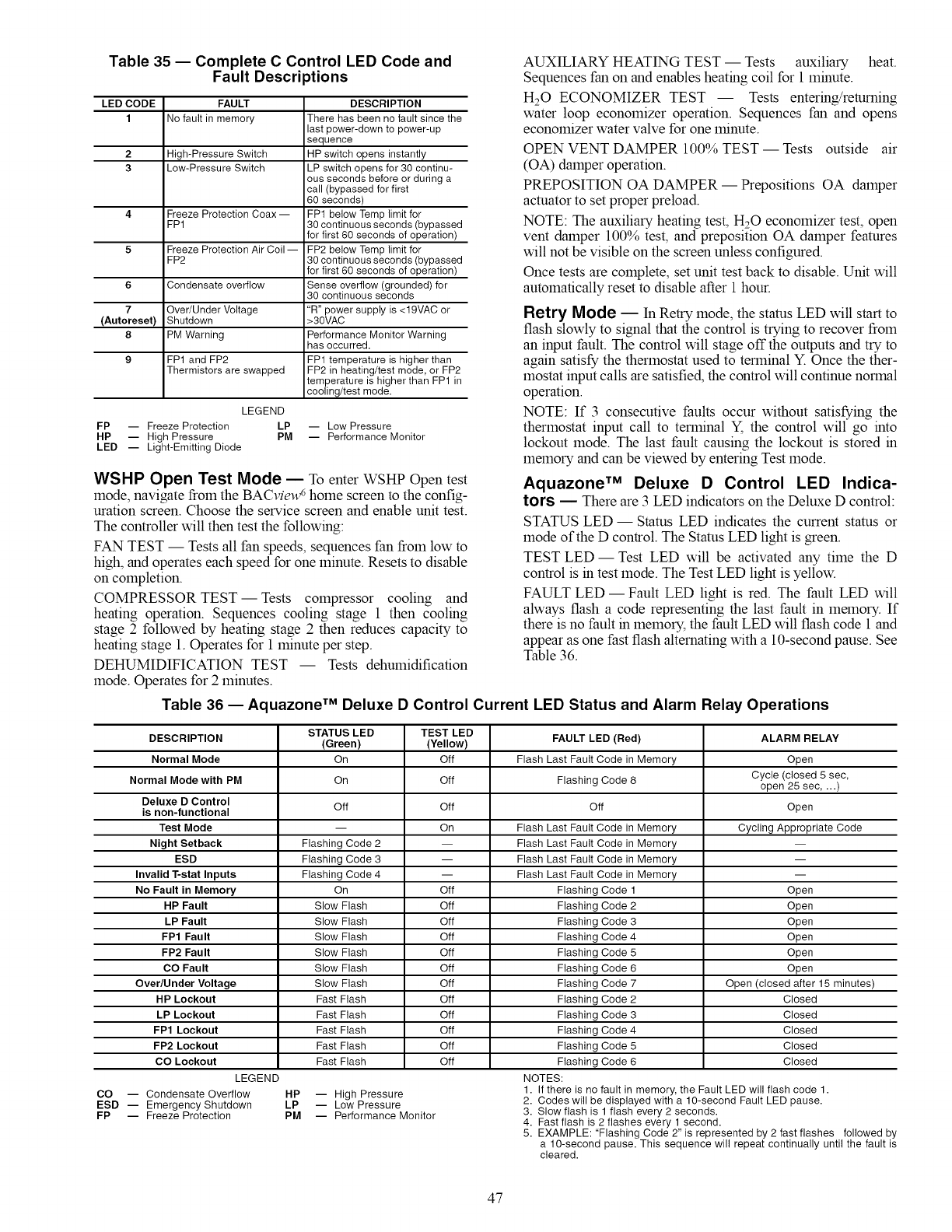
Table 35 -- Complete C Control LED Code and
Fault Descriptions
LED CODE FAULT DESCRIPTION
1No fault in memory There has been no fault since the
last power-down to power-up
sequence
2 High-Pressure Switch HP switch opens instantly
3 Low-Pressure Switch LP switch opens for 30 continu-
ous seconds before or during a
call (bypassed for first
60 seconds)
4 Freeze Protection Coax -- FP1 below Temp limit for
FP1 30 continuous seconds (bypassed
for first 60 seconds of operation)
5 Freeze Protection Air Coil -- FP2 below Temp limit for
FP2 30 continuous seconds (bypassed
for first 60 seconds of operation)
6 Condensate overflow Sense overflow (grounded) for
30 continuous seconds
7 Over/Under Voltage "R" power supply is <19VAC or
(Autoreset) Shutdown >30VAC
8 PM Warning Performance Monitor Warning
has occurred.
9 FP1 and FP2 FP1 temperature is higher than
Thermistors are swapped FP2 in heating/test mode, or FP2
temperature is higher than FP1 in
cooling/test mode.
LEGEND
FP -- Freeze Protection LP -- Low Pressure
HP -- High Pressure PM -- Performance Monitor
LED -- Light-Emitting Diode
WSHP Open Test Mode -- To enter WSHP Open test
mode, navigate from the BACview 6home screen to the config-
uration screen. Choose the service screen and enable unit test.
The controller will then test the following:
FAN TEST -- Tests all fan speeds, sequences fan from low to
high, and operates each speed for one minute. Resets to disable
on completion.
COMPRESSOR TEST--Tests compressor cooling and
heating operation. Sequences cooling stage 1 then cooling
stage 2 followed by heating stage 2 then reduces capacity to
heating stage 1. Operates for 1 minute per step.
DEHUMIDIFICATION TEST -- Tests dehumidification
mode. Operates for 2 minutes.
AUXILIARY HEATING TEST -- Tests auxiliary heat.
Sequences fan on and enables heating coil for 1 minute.
H20 ECONOMIZER TEST -- Tests entering/returning
water loop economizer operation. Sequences fan and opens
economizer water valve for one minute.
OPEN VENT DAMPER 100% TEST -- Tests outside air
(OA) damper operation.
PREPOSITION OA DAMPER -- Prepositions OA damper
actuator to set proper preload.
NOTE: The auxiliary heating test, H20 economizer test, open
vent damper 100% test, and preposition OA damper features
will not be visible on the screen unless configured.
Once tests are complete, set unit test back to disable. Unit will
automatically reset to disable after 1 hour.
Retry Mode -- In Retry mode, the status LED will start to
flash slowly to signal that the control is trying to recover from
an input fault. The control will stage off the outputs and try to
again satisfy the thermostat used to terminal Y. Once the ther-
mostat input calls are satisfied, the control will continue normal
operation.
NOTE: If 3 consecutive faults occur without satisfying the
thermostat input call to terminal Y, the control will go into
lockout mode. The last fault causing the lockout is stored in
memory and can be viewed by entering Test mode.
Aquazone TM Deluxe D Control LED Indica-
tors _ There are 3 LED indicators on the Deluxe D control:
STATUS LED- Status LED indicates the current status or
mode of the D control. The Status LED light is green.
TEST LED- Test LED will be activated any time the D
control is in test mode. The Test LED light is yellow.
FAULT LED -- Fault LED light is red. The fault LED will
always flash a code representing the last fault in memory. If
there is no fault in memory, the fault LED will flash code 1 and
appear as one fast flash alternating with a 10-second pause. See
Table 36.
Table 36 -- Aquazone TM Deluxe D Control Current LED Status and Alarm Relay Operations
DESCRIPTION
Normal Mode
Normal Mode with PM
Deluxe D Control
is non-functional
Test Mode
Night Setback
ESD
Invalid T-stat Inputs
No Fault in Memory
HP Fault
LP Fault
FP1 Fault
FP2 Fault
CO Fault
Over/U nder Voltage
HP Lockout
LP Lockout
FP1 Lockout
FP2 Lockout
CO Lockout
LEGEND
CO -- Condensate Overflow
ESD -- Emergency Shutdown
FP -- Freeze Protection
STATUS LED TEST LED FAULT LED (Red) ALARM RELAY
(Green) (Yellow)
On Off Flash Last Fault Code in Memory Open
On Off Flashing Code 8 Cycle (closed 5 sec,
open 25 sec, ...)
Off Off Open
-- On Cycling Appropriate Code
Flashing Code 2 --
Flashing Code 3 --
Flashing Code 4 --
On Open
Slow Flash Open
Slow Flash Open
Slow Flash Open
Slow Flash Open
Slow Flash Open
Slow Flash Open (closed after 15 minutes)
Fast Flash Closed
Fast Flash Closed
Fast Flash Closed
Fast Flash Closed
Fast Flash Closed
HP -- High Pressure
LP -- Low Pressure
PM -- Performance Monitor
off
Flash Last Fault Code in Memory
Flash Last Fault Code in Memory
Flash Last Fault Code in Memory
Flash Last Fault Code in Memory
Off Flashing Code 1
Off Flashing Code 2
Off Flashing Code 3
Off Flashing Code 4
Off Flashing Code 5
Off Flashing Code 6
Off Flashing Code 7
Off Flashing Code 2
Off Flashing Code 3
Off Flashing Code 4
Off Flashing Code 5
Off Flashing Code 6
NOTES:
1. If there is no fault in memory, the Fault LED will flash code 1.
2. Codes will be displayed with a lO-second Fault LED pause.
3. Slow flash is 1 flash every 2 seconds.
4. Fast flash is 2 flashes every 1 second.
5. EXAMPLE: "Flashing Code 2" is represented by 2 fast flashes followed by
a 10-second pause. This sequence will repeat continually until the fault is
cleared.
47
SERVICE
Perform the procedures outlined below periodically, as
indicated.
To prevent injury or death due to electrical shock or contact
with mov.ing parts, open unit disconnect switch before ser-
vicing umt.
IMPORTANT: When a compressor is removed from this
unit, system refrigerant circuit oil will remain m the com-
pressor. To avoid leakage of compressor oil, the refrigerant
lines of the compressor must be sealed after it is removed.
IMPORTANT: All refrigerant discharged from this unit
must be recovered without exception. Technicians must fol-
low industry accepted guidelines and all local, state and fed-
eral statutes for the recovery and disposal of refrigerants.
IMPORTANT: To avoid the release of refrigerant into the
atmosphere, the refrigerant circuit of this unit must only be
serviced by technicians who meet local, state and federal
proficiency requirements.
Filters -- Filters must be clean for maximum performance.
Inspect filters every month under normal operating conditions.
Replace when necessary.
IMPORTANT: Units should never be operated without ]
a filter. I
Water Coil -- Keep all air out of the water coil. Check
open loop systems to be sure the well head is not allowing air
to infiltrate the water line. Always keep lines airtight.
Inspect heat exchangers regularly, and clean more frequent-
ly if the unit is located in a "dirty" enviromnent. Keep the heat
exchanger full of water at all times. Open loop systems should
have an inverted P trap placed in the discharge line to keep
water m the heat exchanger during off cycles. Closed loop
systems must have a minimum of 15 psig during the smraner
and 40 psig during the winter.
Check P trap frequently for proper operation.
To avoid fouled machinery and extensive unit clean-up,
DO NOT operate units without filters m place. DO NOT
use equipment as a temporary heat source during
construction.
Condensate Drain Pans -- Check condensate drain
pans for algae growth twice a year. If algae growth is apparent,
consult a water treatment specialist for proper chemical treat-
ment. Applying an algaecide every three months will typically
eliminate algae problems in most locations.
Refrigerant System _Verify air and water flow rates
are at proper levels before servicing. To maintain sealed circuit-
ry integrity, do not install service gages unless unit operation
appears abnormal.
Check to see that unit is within the superheat and subcool-
ing temperature ranges shown in Tables 20-30. If the unit is not
within these ranges, recover and reweigh in refrigerant charge.
Compressor -- Conduct annual amperage checks to en-
sure that amp draw is no more than 10% greater than indicated
on the serial plate data.
Fan Motors _All units have lubricated fan motors. Fan
motors should never be lubricated unless obvious, dry opera-
tion is suspected. Periodic maintenance oiling is NOT recom-
mended as it will result m dirt accumulating in the excess oil
and cause eventual motor failure. Conduct annual dry opera-
tion check and amperage check to ensure amp draw is no more
than 10% greater than indicated on serial plate data.
Condensate Drain Cleaning -- Clean the drain line
and unit drain pan at the start of each cooling season. Check
flow by pouring water into drain. Be sure trap is filled to main-
tain an air seal.
Air Coil Cleaning _ Remove dirt and debris from evap-
orator coil as required by condition of the coil. Clean coil with
a stiff brush, vacuum cleaner, or compressed air. Use a fin
comb of the correct tooth spacing when straightening mashed
or bent coil fins.
Condenser Cleaning _Water-cooled condensers may
require cleaning of scale (water deposits) due to improperly
maintained closed-loop water systems. Sludge build-up may
need to be cleaned m an open water tower system due to
induced contaminants.
Local water conditions may cause excessive fouling or
pitting of robes. Condenser robes should therefore be cleaned at
least once a year, or more often if the water is contaminated.
Proper water treatment can minflnize robe fouling and
pitting. If such conditions are anticipated, water treatment
analysis is recolranended. Refer to the Carrier System Design
Manual, Part 5, for general water conditioning information.
Follow all safety codes. Wear safety glasses and rubber
gloves when using inhibited hydrochloric acid solution.
Observe and follow acid manufacturer's instructions.
Clean condensers with an inhibited hydrochloric acid solu-
tion. The acid can stain hands and clothing, damage concrete,
and, without inhibitor, damage steel. Cover surroundings to
guard against splashing. Vapors from vent pipe are not harmful,
but take care to prevent liquid from being carried over by the
gases.
Warm solution acts faster, but cold solution is .just as effec-
tive if applied for a longer period.
GRAVITY FLOW METHOD- Do not add solution faster
than vent can exhaust the generated gases.
When condenser is full, allow solution to remain overnight,
then dram condenser and flush with clean water. Follow acid
manufacturer's instructions. See Fig. 36.
FORCED CIRCULATION METHOD- Fully open vent
pipe when filling condenser. The vent may be closed when
condenser is full and pump is operating. See Fig. 37.
Regulate flow to condenser with a supply line valve. If
pump is a non overloading type, the valve may be fully closed
while pump is running.
For average scale deposit, allow solution to remain m con-
denser overnight. For heavy scale deposit, allow 24 hours.
Drain condenser and flush with clean water. Follow acid manu-
facturer's instructions.
48
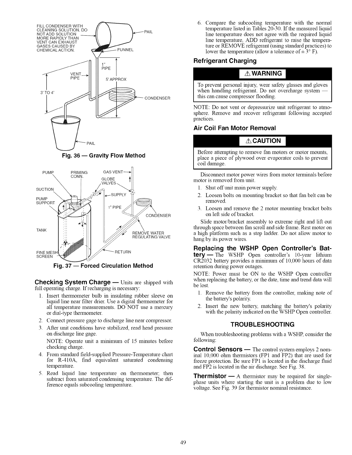
FILL CONDENSER WITH
CLEANING SOLUTION. DO
NOT ADD SOLUTION
MORE RAPIDLY THAN
VENT CAN EXHAUST
GASES CAUSED BY
CHEMICAL ACTION.
pU_NNEL PAlL
5' APPROX
CONDENSER
6. Compare the subcooling temperature with the normal
temperature listed in Tables 20-30. If the measured liquid
line temperature does not agree with the required liquid
line temperature, ADD refrigerant to raise the tempera-
ture or REMOVE refrigerant (using standard practices) to
lower the temperature (allow a tolerance of+ 3° F).
Refrigerant Charging
To prevent personal _jury_ wear safety glasses and gloves
when handling refrigerant. Do not overcharge system --
this can cause compressor flooding.
NOTE: Do not vent or depressurize unit refrigerant to atmo-
sphere. Remove and recover refrigerant following accepted
practices.
Air Coil Fan Motor Removal
Fig. 36 -- Gravity Flow Method
PUMP PRIMING
CONN.
SUCTION
PUMP
SUPPORT
CONDENSER
TANK REMOVE WATER
REGULATING VALVE
FINE MES
SCREEN
RETURN
Fig. 37 -- Forced Circulation Method
Checking System Charge -- Units are shipped with
full operating charge. If recharging is necessary:
1. Insert thermometer bulb in insulating rubber sleeve on
liquid line near filter drier. Use a digital thermometer for
all temperature measurements. DO NOT use a mercury
or dial-type thermometer.
2. Connect pressure gage to discharge line near compressor.
3. After unit conditions have stabilized, read head pressure
on discharge line gage.
NOTE: Operate unit a minimum of 15 minutes before
checking charge.
4. From standard field-supplied Pressure-Temperature chart
for R-410A, find equivalent saturated condensing
temperature.
5. Read liquid line temperature on thermometer; then
subtract from saturated condensing temperature. The dif-
ference equals subcooling temperature.
Before attempting to remove fan motors or motor mounts,
place a piece of plywood over evaporator coils to prevent
coil damage.
Disconnect motor power wires from motor terminals before
motor is removed from unit.
1. Shut offunit main power supply.
2. Loosen bolts on mounting bracket so that fan belt can be
removed.
3. Loosen and remove the 2 motor mounting bracket bolts
on left side of bracket.
Slide motor/bracket assembly to extreme right and lift out
through space between fan scroll and side frame. Rest motor on
a high platform such as a step ladder. Do not allow motor to
hang by its power wires.
Replacing the WSHP Open Controller's Bat-
tery--The WSHP Open controller's 10-year lithium
CR2032 battery provides a minimum of 10,000 hours of data
retention during power outages.
NOTE: Power must be ON to the WSHP Open controller
when replacing the battery, or the date, time and trend data will
be lost.
1. Remove the battery from the controller, making note of
the battery's polarity.
2. Insert the new battery, matching the battery's polarity
with the polarity indicated on the WSHP Open controller.
TROUBLESHOOTING
When troubleshooting problems with a WSHR consider the
following:
Control Sensors -- The control system employs 2 nom-
inal 10,000 ohin thermistors (FP1 and FP2) that are used for
freeze protection. Be sure FP1 is located in the discharge fluid
and FP2 is located in the air discharge. See Fig. 38.
Thermistor- A thermistor may be required for single-
phase units where starting the unit is a problem due to low
voltage. See Fig. 39 for thermistor nominal resistance.
49
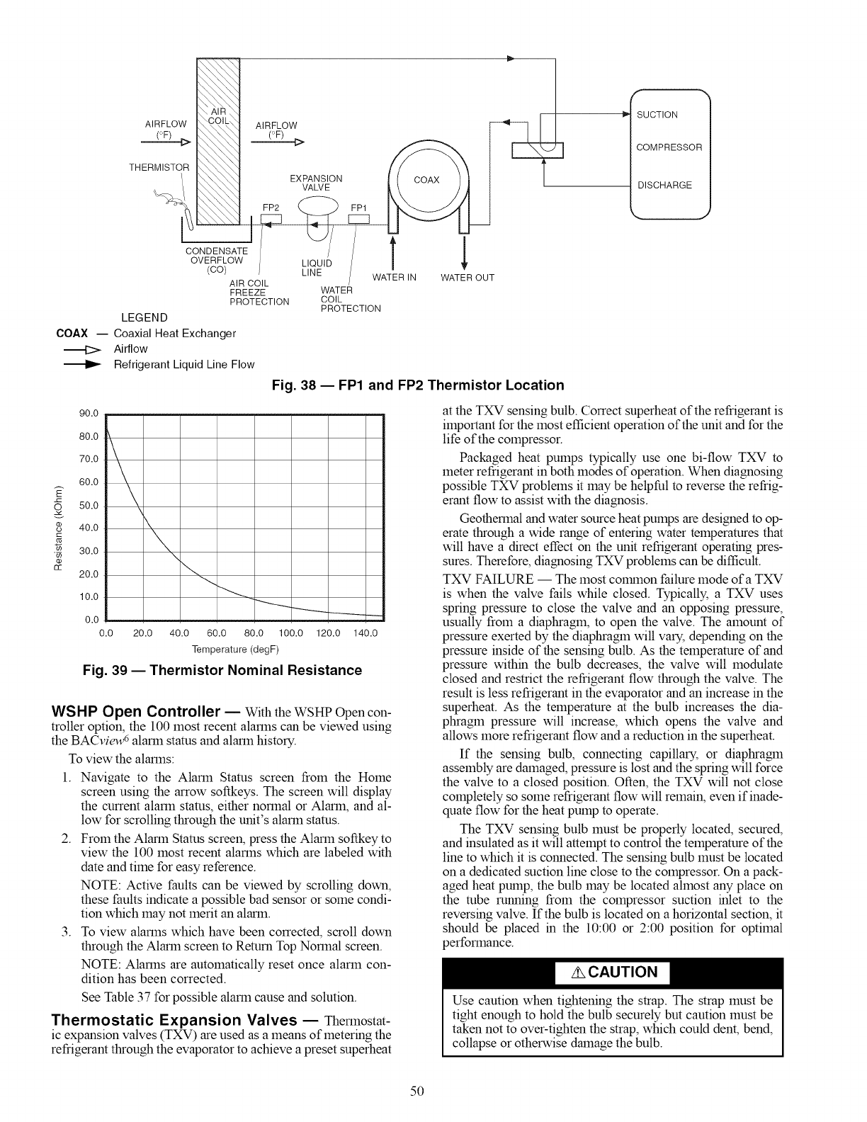
,\ AIR,_
AIRFLOW "_,COIL_
(:'F)
--{>
THERMISTOR
CONDENSATE
OVERFLOW
(co)
AIRFLOW
EXPANSION
VALVE
FP2
AIR COIL
FREEZE
PROTECTION
LEGEND
COAX -- Coaxial Heat Exchanger
Airflow
Refrigerant Liquid Line Flow
FPI
T 1
WATER IN WATER OUT
WATER
COIL
PROTECTION
Fig. 38 -- FP1 and FP2 Thermistor Location
f
SUCTION
COMPRESSOR
DISCHARGE
J
E
3
90.0
80.0
70.0
60.0
50.0
40.0
30.0
20.0
10.0
0.0
0.0
\\\\
20.0 40.0 60.0 80.0 100.0 120.0 140.0
Temperature (degF)
Fig. 39 -- Thermistor Nominal Resistance
WSHP Open Controller -- With the WSHP Open con-
troller option, the 100 most recent alarms can be viewed using
the BACview6 alarm status and alarm history.
To view the alarms:
1. Navigate to the Alarm Status screen from the Home
screen using the arrow softkeys. The screen will display
the current alarm status, either normal or Alarm, and al-
low for scrolling through the unit's alarm status.
2. From the Alarm Status screen, press the Alarm softkey to
view the 100 most recent alarms which are labeled with
date and time for easy reference.
NOTE: Active faults can be viewed by scrolling down,
these faults indicate a possible bad sensor or some condi-
tion which may not merit an alarm.
3. To view alarms which have been corrected, scroll down
through the Alarm screen to Return Top Normal screen.
NOTE: Alarms are automatically reset once alarm con-
dition has been corrected.
See Table 37 for possible alarm cause and solution.
Thermostatic Expansion Valves -- Thermostat-
ic expansion valves (TXV) are used as a means of metering the
refrigerant through the evaporator to achieve a preset superheat
at the TXV sensing bulb. Correct superheat of the refrigerant is
important for the most efficient operation of the unit and for the
life of the compressor.
Packaged heat pumps typically use one bi-flow TXV to
meter refrigerant in both modes of operation. When diagnosing
possible TXV problems it may be helpful to reverse the refrig-
erant flow to assist with the diagnosis.
Geothermal and water source heat pumps are designed to op-
erate through a wide range of entering water temperatures that
will have a direct effect on the unit refrigerant operating pres-
sures. Therefore, diagnosing TXV problems can be difficult.
TXV FAILURE -- The most colnmon failure mode ofa TXV
is when the valve fails while closed. Typically, a TXV uses
spring pressure to close the valve and an opposing pressure,
usually from a diaphragm, to open the valve. The amount of
pressure exerted by the diaphragm will vary, depending on the
pressure inside of the sensing bulb. As the temperature of and
pressure within the bulb decreases, the valve will modulate
closed and restrict the refrigerant flow through the valve. The
result is less refrigerant in the evaporator and an increase in the
superheat. As the temperature at the bulb increases the dia-
phragm pressure will increase, which opens the valve and
allows more refrigerant flow and a reduction in the superheat.
If the sensing bulb, connecting capillary, or diaphragm
assembly are damaged, pressure is lost and the spring will force
the valve to a closed position. Often, the TXV will not close
completely so some refrigerant flow will remain, even if inade-
quate flow for the heat pump to operate.
The TXV sensing bulb must be properly located, secured,
and insulated as it will attempt to control the temperature of the
line to which it is connected. The sensing bulb must be located
on a dedicated suction line close to the compressor. On a pack-
aged heat pump, the bulb may be located ahnost any place on
the tube running from the compressor suction inlet to the
reversing valve. If the bulb is located on a horizontal section, it
should be placed in the 10:00 or 2:00 position for optimal
performance.
Use caution when tightening the strap. The strap must be
tight enough to hold the bulb securely but caution must be
taken not to over-tighten the strap, which could dent, bend,
collapse or otherwise damage the bulb.
5O
Thebulbmustbesecuredtothepipeusingacopperstrap.
Theuseofheattransferpastebetweenthebulbandthepipe
willalsohelpensureoptimumperformance.
Thebulbmustalsobeproperlyinsulatedtoeliminateany
influenceonvalveoperationbythesurroundingconditions.
Corktapeistherecommendedinsulationasit canbemolded
tighttothebulbtopreventairinfiltration.
Causes of TXV Failure -- The most common causes of TXV
failure are:
1. A cracked, broken, or damaged sensing bulb or capillary
can be caused by excessive vibration of the capillary dur-
ing shipping or unit operation.
If the sensing bulb is damaged or if the capillary is
cracked or broken, the valve will be considered failed and
must be replaced. Replacement of the TXV "power head"
or sensing bulb, capillary, diaphragm assembly is possible
on some TXVs. The power head assembly screws onto
most valves, but not all are intended to be replaceable. If
the assembly is not replaceable, replace the entire valve.
2. Particulate debris within the system can be caused by sev-
eral sources including contaminated components, robing,
and service tools, or improper techniques used during
brazing operations and component replacement.
Problems associated with particulate debris can be coin-
pounded by refrigerant systems that use POE (polyol es-
ter oil). POE oil has solvent-like properties that will clean
the interior surfaces of robing and components. Particu-
lates can be released from interior surfaces and may mi-
grate to the TXV strainer, which can lead to plugging of
the strainer.
3. Corrosive debris within the system may happen after a
failure, such as a compressor burn out, if system was not
properly cleaned.
4. Noncondensables may be present in the system. Non-
condensables includes any substance other than the
refrigerant or oil such as air, nitrogen, or water. Contan_-
nation can be the result of improper service techniques,
use of contaminated components, and/or improper evacu-
ation of the system.
Symptoms -- The symptoms of a failed TXV can be varied
and will include one or more of the following:
• Low refrigerant suction pressure
• High refrigerant superheat
• High refrigerant subcoolmg
• TXV and/or low pressure robing frosting
• Equalizer line condensing and at a lower temperature than
the suction line or the equalizer line frosting
• FP1 faults in the heating mode in combination with any of
the symptoms listed above
• FP2 faults in the cooling mode in combination with any of
the symptoms listed above. Some symptoms can mimic a
failed TXV but may actually be caused be another problem.
Before conducting an analysis for a failed TXV the follow-
ing must be verified:
• Confirm that there is proper water flow and water tempera-
rare in the heating mode.
• Confirm that there is proper airflow and temperature in the
cooling mode.
• Ensure coaxial water coil is clean on the reside; this applies
to the heating mode and may require a scale check.
• Refrigerant may be undercharged. To verify, subcooling and
superheat calculations may be required.
Diagnostics--Several tests may be required to determine if
a TXV has failed. The following tools may be required for
testing:
1. Refrigerant gage manifold compatible with the refriger-
ant in the system
2. Digital thermometer, preferably insulated, with wire leads
that can be connected directly to the tubing
3. Refrigerant pressure-temperature chart for the refrigerant
used
To determine that a TXV has failed, verify the following:
• The suction pressure is low and the valve is non-responsive.
The TXV sensing bulb can be removed from the suction
line and warmed by holding the bulb in your hand. This
action should result in an increase in the suction pressure
while the compressor is operating. The sensing bulb can
also be chilled by immersion in ice water, which should
result in a decrease in the suction pressure while the
compressor is operating. No change in the suction pres-
sure would indicate a nonresponsive valve.
• Simultaneous LOW suction pressure, HIGH refrigerant
subcooling and HIGH superheat may indicate a failed
valve.
• LOW suction pressure, LOW subcoolmg and HIGH super-
heat may indicate an undercharge of refrigerant. HIGH sub-
cooling and LOW superheat may indicate an overcharge of
refrigerant. The suction pressure will usually be normal or
high if there is an overcharge of refrigerant.
• LOW suction pressure and frosting of the valve and/or
equalizer line may indicate a failed valve. However, these
symptoms may also indicate an undercharge of refrigerant.
Calculate the subcoolmg and superheat to verify a failed
valve or refrigerant charge issue.
Puron :R_refrigerant (R-410A) operates at higher pressure
than R-22, which is found in other WSHPs. Tools such as
manifold gages must be rated to withstand the higher pres-
sures. Failure to use approved tools may result in a failure
of tools, which can lead to severe damage to the unit, injury
or death.
Most TXVs are designed for a fixed superheat setting and
are therefore considered non-adjustable. Removal of the
bottom cap will not provide access for adjustinent and can
lead to damage to the valve or equipment, unintended vent-
ing of refrigerant, personal iniury, or possibly death.
Use caution when tightening the strap. The strap must be
tight enough to hold the bulb securely but caution must be
taken not to over-tighten the strap, which could dent, bend,
collapse or otherwise damage the bulb.
Puron refrigerant (R-410A) requires the use of synthetic
lubricant (POE oil). Do not use coirnnon tools on systems
that contain R-22 refrigerants or mineral oil. Contamina-
tion and failure of this equipment may result.
51
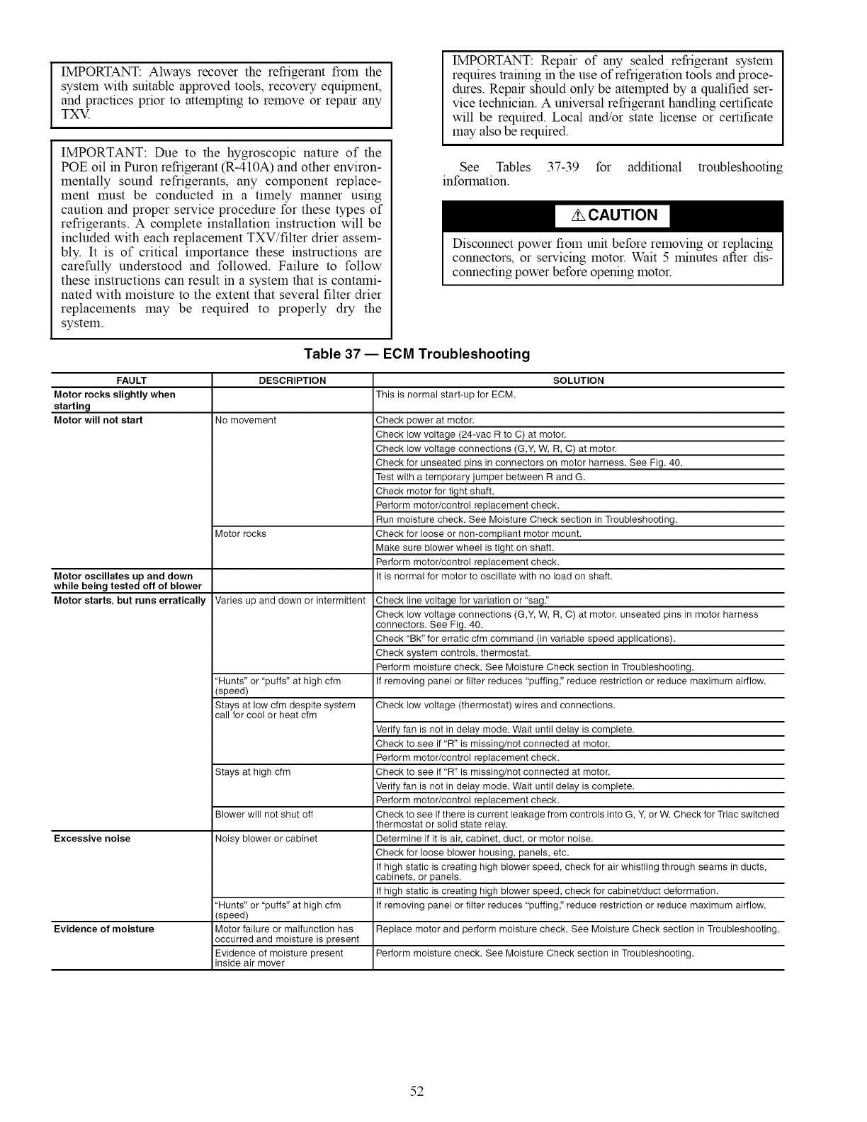
IMPORTANT: Always recover the refrigerant from the
system with suitable approved tools, recovery equipment,
and practices prior to attempting to remove or repair any
TX_.
IMPORTANT: Due to the hygroscopic nature of the
POE oil in Puron refrigerant (R-410A) and other environ-
mentally sound refrigerants, any component replace-
ment must be conducted in a timely manner using
caution and proper service procedure for these types of
refrigerants. A complete installation instruction will be
included with each replacement TXV/filter drier assem-
bly. It is of critical importance these instructions are
carefully understood and followed. Failure to follow
these instructions can result in a system that is contami-
nated with moisture to the extent that several filter drier
replacements may be required to properly dry the
system.
IMPORTANT: Repair of any sealed refrigerant system
requires training in the use of refrigeration tools and proce-
dures. Repair should only be attempted by a qualified ser-
vice technician. A universal refrigerant handling certificate
will be required. Local and/or state license or certificate
may also be required.
See Tables 37-39 for additional troubleshooting
information.
Disconnect power from unit before removing or replacing
connectors, or servicing motor. Wait 5 minutes after dis-
connecting power before opening motor.
Table 37 -- ECM Troubleshooting
FAULT DESCRIPTION SOLUTION
Motor rocks slightly when This is normal start-up for ECM.
starting
Motor will not start No movement
Motor oscillates up and down
while being tested off of blower
Motor starts, but runs erratically
Motor rocks
Varies up and down or intermittent
"Hunts" or "puffs" at high cfm
(speed)
Stays at low cfm despite system
call for cool or heat cfm
Stays at high cfm
Blower will not shut off
Excessive noise Noisy blower or cabinet
Evidence of moisture
"Hunts" or "puffs" at high cfm
(speed)
Motor failure or malfunction has
occurred and moisture is present
Evidence of moisture present
inside air mover
Check power at motor.
Check low voltage (24-vac R to C) at motor.
Check low voltage connections (G,Y, W, R, C) at motor.
Check for unseated pins in connectors on motor harness. See Fig. 40.
Test with a temporary jumper between R and G.
Check motor for tight shaft.
Perform motor/control replacement check.
Run moisture check. See Moisture Check section in Troubleshooting.
Check for loose or non-compliant motor mount.
Make sure blower wheel is tight on shaft.
Perform motor/control replacement check.
It is normal for motor to oscillate with no load on shaft.
Check line voltage for variation or "sag."
Check low voltage connections (G,Y, W, R, C) at motor, unseated pins in motor harness
connectors. See Fig. 40.
Check "Bk" for erratic cfm command (in variable speed applications).
Check system controls, thermostat.
Perform moisture check. See Moisture Check section in Troubleshooting.
If removing panel or filter reduces "puffing," reduce restriction or reduce maximum airflow.
Check low voltage (thermostat) wires and connections.
Verify fan is not in delay mode. Wait until delay is complete.
Check to see if "R" is missing/not connected at motor.
Perform motor/control replacement check.
Check to see if "R" is missing/not connected at motor.
Verify fan is not in delay mode. Wait until delay is complete.
Perform motor/control replacement check.
Check to see if there is current leakage from controls into G, Y, or W. Check for Triac switched
thermostat or solid state relay.
Determine if it is air, cabinet, duct, or motor noise.
Check for loose blower housing, panels, etc.
If high static is creating high blower speed, check for air whistling through seams in ducts,
cabinets, or panels.
If high static is creating high blower speed, check for cabinet/duct deformation.
If removing panel or filter reduces "puffing," reduce restriction or reduce maximum airflow.
Replace motor and perform moisture check. See Moisture Check section in Troubleshooting.
Perform moisture check. See Moisture Check section in Troubleshooting.
52
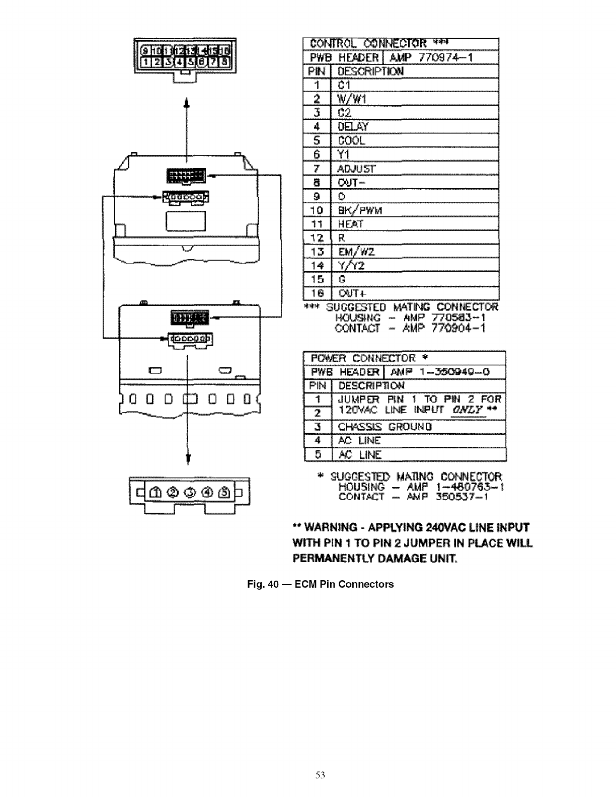
CO_ROL _N_OTOR "_
_j
C3
OQD DO00
m
[
l
I
_T-
i¢t
.......3.........
4OEL_¥
S COOL
7A{X_U_
9
......]0 BK/PW_ .....................................................
11 HEA-r
...._2 R
15
i6 _T4-
i_J_NC - AMP 77_3-_
P_R CONN_OR *
PWB H_D_] _aP 1-_4g--O
PiN DESCmP_
1JLI:_P_ RH t 'TO PU'_ 2FOR
! 2_¢AC Llb_ INP_r oNLY
3C_3_ C_UN D
4 _ UNZ
_USiN_ - A_P
"" WARNING- APPLYING 2_JqAC LINE INPL_
W_ PiN _ 'TO PIN 2 JUMPER IN P_CE W!_
PER_N_NTLY D_AGE UNIT_
Fig. 40 -- ECM Pin Connectors
53
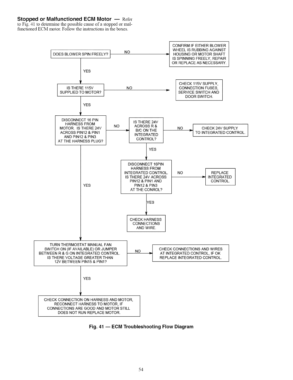
Stopped or Malfunctioned ECM Motor -- Refer
to Fig. 41 to determine the possible cause of a stopped or mal-
functioned ECM motor. Follow the instructions in the boxes.
DOES BLOWER SPIN FREELY? J
YES
NO
CONFIRM _FEITHER BLOWER
WHEEL IS RUBBING AGAINST
HOUSING OR MOTOR SHAFT
IS SPINNING FREELY, REPA1R
OR REPLACE AS NECESSARY.
I
IS THERE 115V I
SUPPUEO TO MOTOR? I
11YES
D_SCONNECT 16 P_N
HARNESS FROM
MOTOR_ IS THERE 24V
ACROSS PIN12 & PIN!
AND P_N12 & PIN3
AT THE HARNESS PLUG?
YES
NO
NO
_[ S THERE 24V
ACROSS R &
B/C ON THE
_NTEGRATED
CONTROL?
I YES
DISCONNECT 16PIN
HARNESS FROM
INTEGRATED CONTROL
_STHERE 24V ACROSS
PIN12 & PIN1 AND
PIN12 & PIN3
AT THE _NROL?
YES
l CHECK HARNESS
CONNECTIONS
AND WIRE.
'CHECK 115V SUPPLY,
CONNECTION FUSES,
SERVICE SWITCH AND
DOOR SWITCH.
NO _ CHECK 24V SUPPLYTO #_4ffEGRATED CONTROL
NO _ REPLACE
_NTEGRATED
CONTROL.
TURN THERMOSTAT MANUAL FAN
SWITCH ON {IF AVAILABLE) OR JUMPER
BE'Fv'VEEN R & G ON INTEGRATED CON_OL.
IS THERE VOLTAGE GREA_R THAN
12V BEP¢TEEN P_N15 & PIN1?
NO CHECK CONNECTIONS _D W_RES
AT INTEGRATED CONTROL IF OK
REPLACE INTEGRATED CONTROL
YES
CHECK CONNECTION ON HARNESS AND MOTOR,
RECONNECT HARNESS TO MOTOR ;F
C_NECT_ONS ARE GOOO AND MOTOR STIL
DOES NOT RUN REPLACE MOTOR_
Fig. 41 -- ECM Troubleshooting Flow Diagram
54
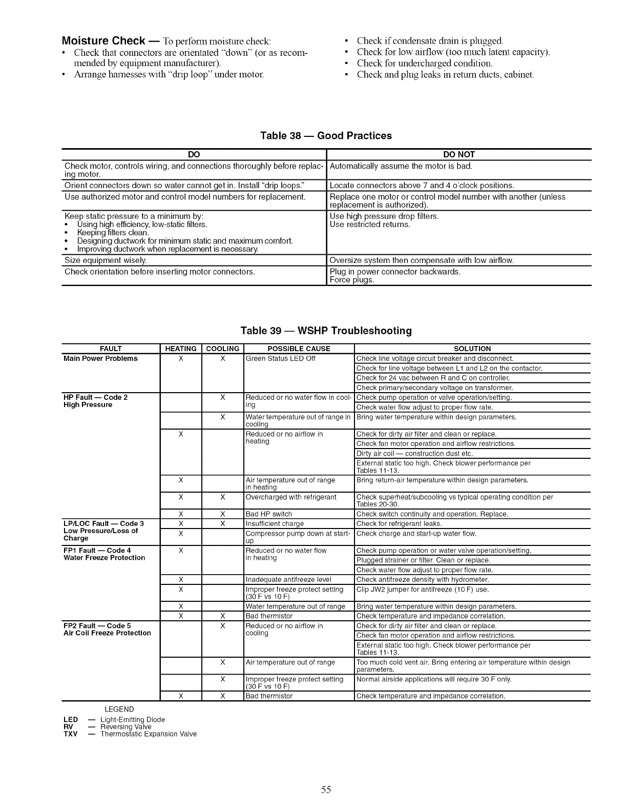
Moisture Check -- To perform moisture check:
•Check that connectors are orientated "down" (or as recom-
mended by equipment manufacturer).
• Arrange harnesses with "drip loop" under motor.
• Check if condensate drain is plugged.
• Check for low airflow (too much latent capacity).
• Check for undercharged condition.
• Check and plug leaks in return ducts, cabinet.
Table 38 -- Good Practices
DO DO NOT
Check motor, controls wiring, and connections thoroughly before replac- Automatically assume the motor is bad,
ing motor,
Orient connectors down so water cannot get in, Install "drip loops." Locate connectors above 7 and 4 o'clock positions,
Use authorized motor and control model numbers for replacement, Replace one motor or control model number with another (unless
replacement is authorized),
Keep static pressure to a minimum by: Use high pressure drop filters,
• Using high efficiency, low-static filters, Use restricted returns,
• Keeping filters clean,
• Designing ductwork for minimum static and maximum comfort,
• Improving ductwork when replacement is necessary.
Size equipment wisely. Oversize system then compensate with low airflow,
Check orientation before inserting motor connectors, Plug in power connector backwards,
Force plugs,
Table 39 -- WSHP Troubleshooting
FAULT HEATING COOLING POSSIBLE CAUSE
Main Power Problems X X Green Status LED Off
HP Fault -- Code 2
High Pressure
LP/LOC Fault -- Code 3
Low Pressure/Loss of
Charge
FP1 Fault -- Code 4
Water Freeze Protection
FP2 Fault -- Code 5
Air Coil Freeze Protection
LEGEND
LED -- Light-Emitting Diode
RV -- Reversing Valve
TXV
X
X
x
x
x
x
x
x
x
x
x
x
x
x
x
x
x
x
Reduced or no water flow in cool-
ing
Water temperature out of range in
cooling
Reduced or no airflow in
heating
Air temperature out of range
in heating
Overcharged with refrigerant
Bad HP switch
Insufficient charge
Compressor pump down at start-
up
Reduced or no water flow
in heating
Inadequate antifreeze level
Improper freeze protect setting
(30 F vs 10 F)
Water temperature out of range
Bad thermistor
Reduced or no airflow in
cooling
Air temperature out of range
Improper freeze protect setting
(30 F vs 10 F)
Bad thermistor
SOLUTION
Check line voltage circuit breaker and disconnect.
Check for line voltage between L1 and L2 on the contactor.
Check for 24 vac between R and C on controller.
Check primary/secondary voltage on transformer.
Check pump operation or valve operation/setting.
Check water flow adjust to proper flow rate.
Bring water temperature within design parameters.
Check for dirty air filter and clean or replace.
Check fan motor operation and airflow restrictions.
Dirty air coil -- construction dust etc.
External static too high. Check blower performance per
Tables 11-13.
Bring return-air temperature within design parameters.
Check superheat/subcooling vs typical operating condition per
Tables 20-30.
Check switch continuity and operation. Replace.
Check for refrigerant leaks.
Check charge and start-up water flow.
Check pump operation or water valve operation/setting.
Plugged strainer or filter. Clean or replace.
Check water flow adjust to proper flow rate.
Check antifreeze density with hydrometer.
Clip JW2 jumper for antifreeze (10 F) use.
Bring water temperature within design parameters.
Check temperature and impedance correlation.
Check for dirty air filter and clean or replace.
Check fan motor operation and airflow restrictions.
External static too high. Check blower performance per
Tables 11-13.
Too much cold vent air. Bring entering air temperature within design
)arameters.
Normal airside applications will require 30 F only.
Check temperature and impedance correlation.
-- Thermostatic Expansion Valve
55
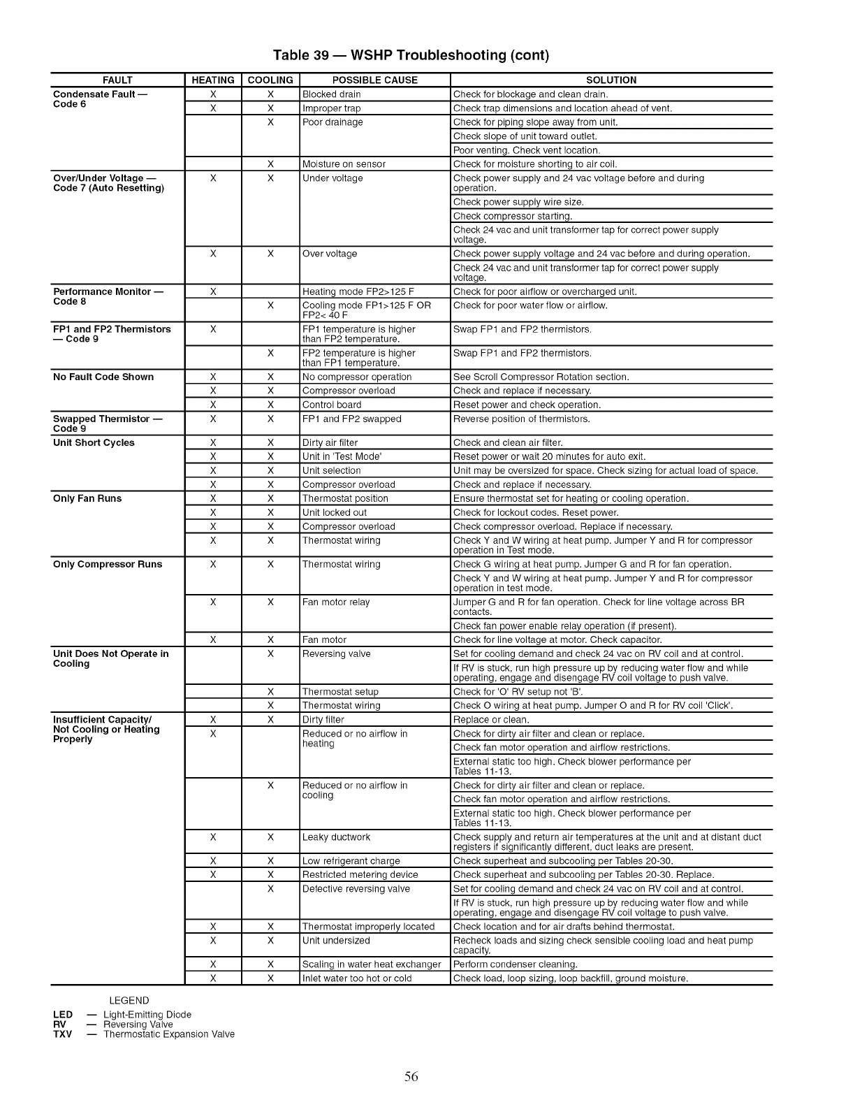
Table 39 -- WSHP Troubleshooting (cont)
FAULT
Condensate Fault-
Code 6
Over/Under Voltage --
Code 7 (Auto Resetting)
Performance Monitor --
Code 8
FP1 and FP2 Thermistors
-- Code 9
No Fault Code Shown
Swapped Thermistor --
Code 9
Unit Short Cycles
Only Fan Runs
Only Compressor Runs
Unit Does Not Operate in
Cooling
Insufficient Capacity/
Not Cooling or Heating
Properly
HEATING
X
X
COOLING
X
X
X
X
X
X
X
POSSIBLE CAUSE
Blocked drain
Improper trap
Poor drainage
Moisture on sensor
Under voltage
Over voltage
SOLUTION
Check for blockage and clean drain.
Check trap dimensions and location ahead of vent.
Check for piping slope away from unit.
Check slope of unit toward outlet.
Poor venting. Check vent location.
Check for moisture shorting to air coil.
Check power supply and 24 vac voltage before and during
operation.
Check power supply wire size.
Check compressor starting.
Check 24 vac and unit transformer tap for correct power supply
voltage.
Check power supply voltage and 24 vac before and during operation.
Check 24 vac and unit transformer tap for correct power supply
voltage.
Check for poor airflow or overcharged unit.
Check for poor water flow or airflow.
X Swap FP1 and FP2 thermistors.
X Swap FP1 and FP2 thermistors.
x
x
x
x
x
x
x
x
x
x
x
x
x
x
x
x
x
x
x
x
x
x
x
x
x
x
x
x
x
x
x
x x
x x
x x
x
x
x
x
x
x
x
Heating mode FP2>125 F
Cooling mode FP1>125 F OR
FP2< 40 F
FP1 temperature is higher
than FP2 temperature.
FP2 temperature is higher
than FP1 temperature.
No compressor operation
Compressor overload
Control board
FP1 and FP2 swapped
Dirty air filter
Unit in 'Test Mode'
Unit selection
Compressor overload
Thermostat position
Unit locked out
Compressor overload
Thermostat wiring
Thermostat wiring
Fan motor relay
Fan motor
Reversing valve
Thermostat setup
Thermostat wiring
Dirty filter
Reduced or no airflow in
heating
Reduced or no airflow in
cooling
Leaky ductwork
Low refrigerant charge
Restricted metering device
Defective reversing valve
Thermostat improperly located
Unit undersized
Scaling in water heat exchanger
Inlet water too hot or cold
X
X
See Scroll Compressor Rotation section.
Check and replace if necessary.
Reset power and check operation.
Reverse position of thermistors.
Check and clean air filter.
Reset power or wait 20 minutes for auto exit.
Unit may be oversized for space. Check sizing for actual load of space.
Check and replace if necessary.
Ensure thermostat set for heating or cooling operation.
Check for lockout codes. Reset power.
Check compressor overload. Replace if necessary.
Check Y and W wiring at heat pump. Jumper Y and R for compressor
operation in Test mode.
Check G wiring at heat pump. Jumper G and R for fan operation.
Check Y and W wiring at heat pump. Jumper Y and R for compressor
operation in test mode.
Jumper G and R for fan operation. Check for line voltage across BR
contacts.
Check fan power enable relay operation (if present).
Check for line voltage at motor. Check capacitor.
Set for cooling demand and check 24 vac on RV coil and at control.
If RV is stuck, run high pressure up by reducing water flow and while
operating, engage and disengage RV coil voltage to push valve.
Check for 'O' RV setup not 'B'.
Check O wiring at heat pump. Jumper O and R for RV coil 'Click'.
Replace or clean.
Check for dirty air filter and clean or replace.
Check fan motor operation and airflow restrictions.
External static too high. Check blower performance per
Tables 11-13.
Check for dirty air filter and clean or replace.
Check fan motor operation and airflow restrictions.
External static too high. Check blower performance per
Tables 11-13.
Check supply and return air temperatures at the unit and at distant duct
registers if significantly different, duct leaks are present.
Check superheat and subcooling per Tables 20-30.
Check superheat and subcooling per Tables 20-30. Replace.
Set for cooling demand and check 24 vac on RV coil and at control.
If RV is stuck, run high pressure up by reducing water flow and while
operating, engage and disengage RV coil voltage to push valve.
Check location and for air drafts behind thermostat.
Recheck loads and sizing check sensible cooling load and heat pump
capacity.
Perform condenser cleaning.
Check load, loop sizing, loop backfill, ground moisture.
LEGEND
LED -- Light-Emitting Diode
RV -- Reversing Valve
TXV -- Thermostatic Expansion Valve
56
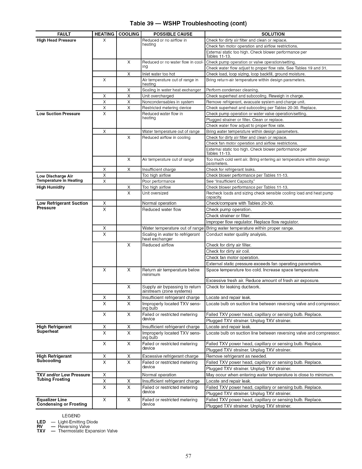
Table 39 -- WSHP Troubleshooting (cont)
FAULT HEATING
High Head Pressure X
Low Suction Pressure
Low Discharge Air
Temperature in Heating
High Humidity
Low Refrigerant Suction
Pressure
High Refrigerant
Superheat
High Refrigerant
Subcooling
x
x
x
x
COOLING
X
X
x
x
x
x
x
x
x
x
x
x
x
x
x
POSSIBLE CAUSE
Reduced or no airflow in
heating
Reduced or no water flow in cool-
mg
Inlet water too hot
Air temperature out of range in
heating
Scaling in water heat exchanger
Unit overcharged
Noncondensables in system
Restricted metering device
Reduced water flow in
heating
Water temperature out of range
Reduced airflow in cooling
Air temperature out of range
Insufficient charge
Too high airflow
Poor performance
Too high airflow
Unit oversized
X Normal operation
X Reduced water flow
X Water temperature out of range
X Scaling in water to refrigerant
heat exchanger
X Reduced airflow
x
x
x
x
x
x
x
x
x
Return air temperature below
minimum
x
x
x
SOLUTION
Check for dirty air filter and clean or replace.
Check fan motor operation and airflow restrictions.
External static too high. Check blower performance per
Tables 11 -13.
Check pump operation or valve operation/setting.
Check water flow adjust to proper flow rate. See Tables 19 and 31.
Check load, loop sizing, loop backfill, ground moisture.
Bring return-air temperature within design parameters.
Perform condenser cleaning.
Check superheat and subcooling. Reweigh in charge.
Remove refrigerant, evacuate system and charge unit.
Check superheat and subcooling per Tables 20-30. Replace.
Check pump operation or water valve operation/setting.
Plugged strainer or filter. Clean or replace.
Check water flow adjust to proper flow rate.
Bring water temperature within design parameters.
Check for dirty air filter and clean or replace.
Check fan motor operation and airflow restrictions.
External static too high. Check blower performance per
Tables 11-13.
Too much cold vent air. Bring entering air temperature within design
3arameters.
Check for refrigerant leaks.
Check blower performance per Tables 11-13.
See "Insufficient Capacity."
Check blower performance per Tables 11-13.
Recheck loads and sizing check sensible cooling load and heat pump
capacity.
Check/compare with Tables 20-30.
Check pump operation.
Check strainer or filter.
Improper flow regulator. Replace flow regulator.
Bring water temperature within proper range.
Conduct water quality analysis.
Check for dirty air filter.
Check for dirty air coil.
Check fan motor operation.
External static pressure exceeds fan operating parameters.
Space temperature too cold. Increase space temperature.
Excessive fresh air. Reduce amount of fresh air exposure.
Check for leaking ductwork.
X Locate and repair leak.
X Locate bulb on suction line between reversing valve and compressor.
X Failed TXV power head, capillary or sensing bulb. Replace.
Plugged TXV strainer. Unplug TXV strainer.
Locate and repair leak.
Locate bulb on suction line between reversing valve and compressor.
x
x
Supply air bypassing to return
airstream (zone systems)
Insufficient refrigerant charge
Improperly located TXV sens-
ing bulb
Failed or restricted metering
device
Insufficient refrigerant charge
Improperly located TXV sens-
ing bulb
Failed or restricted metering
device
Excessive refrigerant charge
Failed or restricted metering
device
Normal operation
Insufficient refrigerant charge
Failed or restricted metering
device
Failed or restricted metering
device
TXV and/or Low Pressure X
Tubing Frosting X
X
Equalizer Line
Condensing or Frosting
X
X
Failed TXV power head, capillary or sensing bulb. Replace.
Plugged TXV strainer. Unplug TXV strainer.
Remove refrigerant as needed.
Failed TXV power head, capillary or sensing bulb. Replace.
Plugged TXV strainer. Unplug TXV strainer.
May occur when entering water temperature is close to minimum.
Locate and repair leak.
Failed TXV power head, capillary or sensing bulb. Replace.
Plugged TXV strainer. Unplug TXV strainer.
Failed TXV power head, capillary or sensing bulb. Replace.
Plugged TXV strainer. Unplug TXV strainer.
LEGEND
LED -- Light-Emitting Diode
RV -- Reversing Valve
TXV -- Thermostatic Expansion Valve
57
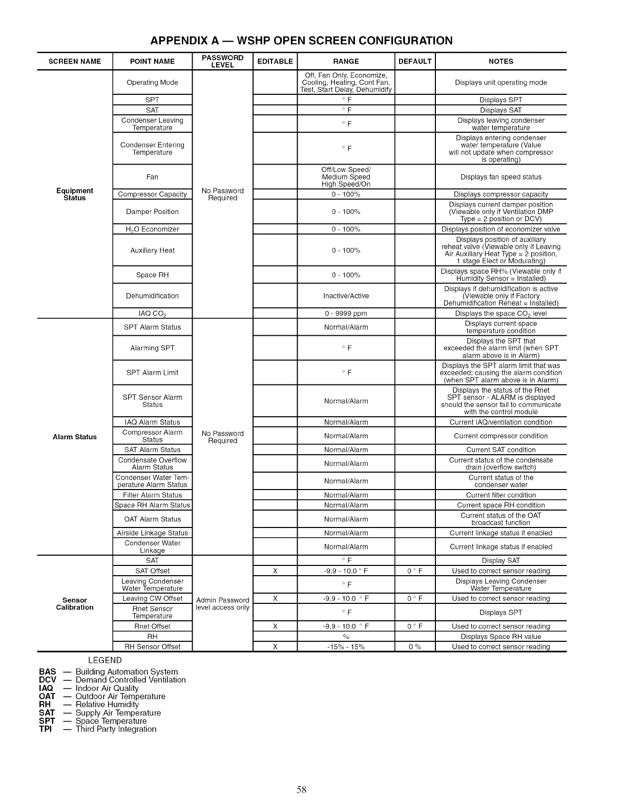
APPENDIX A EWSHP OPEN SCREEN CONFIGURATION
SCREEN NAME
Equipment
Status
Alarm Status
Sensor
Calibration
POINT NAME
Operating Mode
SPT
SAT
Condenser Leaving
Temperature
Condenser Entering
Temperature
Fan
Compressor Capacity
Damper Position
H20 Economizer
Auxiliary Heat
Space RH
Dehumidification
IAQ CO 2
SPT Alarm Status
Alarming SPT
SPT Alarm Limit
SPT Sensor Alarm
Status
IAQ Alarm Status
Compressor Alarm
Status
SAT Alarm Status
Condensate Overflow
Alarm Status
Condenser Water Tem-
perature Alarm Status
Filter Alarm Status
Space RH Alarm Status
OAT Alarm Status
Airside Linkage Status
Condenser Water
Linkage
SAT
SAT Offset
Leaving Condenser
Water Temperatu re
Leaving CW Offset
Rnet Sensor
Temperature
Rnet Offset
RH
RH Sensor Offset
PASSWORD
LEVEL
No Password
Required
No Password
Required
Admin Password
level access only
EDITABLE
X
X
RANGE DEFAULT NOTES
Off, Fan Only, Economize,
Cooling, Heating, Cont Fan,
Test, Start Delay, Dehumidify
o F
o F
o F
o F
Off/Low Speed/
Medium Speed
High Speed/On
0- 100%
0 - 100%
0- 100%
0 - 100%
0 - 100%
Inactive/Active
0 - 9999 ppm
Normal/Alarm
o F
o F
Normal/Alarm
Normal/Alarm
Normal/Alarm
Normal/Alarm
Normal/Alarm
Normal/Alarm
Normal/Alarm
Normal/Alarm
Normal/Alarm
Normal/Alarm
Normal/Alarm
o F
-9.9-10.0° F
o F
-9.9- 10.0 o F
o F
-9.9- 10.0 o F
%
-15% - 15%
0OF
0OF
0°F
O%
Displays unit operating mode
Displays SPT
Displays SAT
Displays leaving condenser
water temperature
Displays entering condenser
water temperature (Value
will not update when compressor
is operating)
Displays fan speed status
Displays compressor capacity
Displays current damper position
(Viewable only if Ventilation DMP
Type = 2 position or DCV)
Displays position of economizer valve
Displays position of auxiliary
reheat valve (Viewable only if Leaving
Air Auxiliary Heat Type = 2 position,
1 stage Elect or Modulating)
Displays space RH% (Viewable only if
Humidity Sensor = Installed)
Displays if dehumidification is active
(Viewable only if Factory
Dehumidification Reheat = Installed)
Displays the space CO2 level
Displays current space
temperature condition
Displays the SPT that
exceeded the alarm limit (when SPT
alarm above is in Alarm)
Displays the SPT alarm limit that was
exceeded; causing the alarm condition
(when SPT alarm above is in Alarm)
Displays the status of the Rnet
SPT sensor - ALARM is displayed
should the sensor fail to communicate
with the control module
Current IAQ/ventilation condition
Current compressor condition
Current SAT condition
Current status of the condensate
drain (overflow switch)
Current status of the
condenser water
Current filter condition
Current space RH condition
Current status of the OAT
broadcast function
Current linkage status if enabled
Current linkage status if enabled
Display SAT
Used to correct sensor reading
Displays Leaving Condenser
Water Temperature
Used to correct sensor reading
Displays SPT
Used to correct sensor reading
Displays Space RH value
Used to correct sensor reading
LEGEND
BAS -- Building Automation System
DCV -- Demand Controlled Ventilation
IAQ -- Indoor Air Quality
OAT -- Outdoor Air Temperature
RH -- Relative Humidity
SAT -- Supply Air Temperature
SPT -- Space Temperature
TPI -- Third Party Integration
58
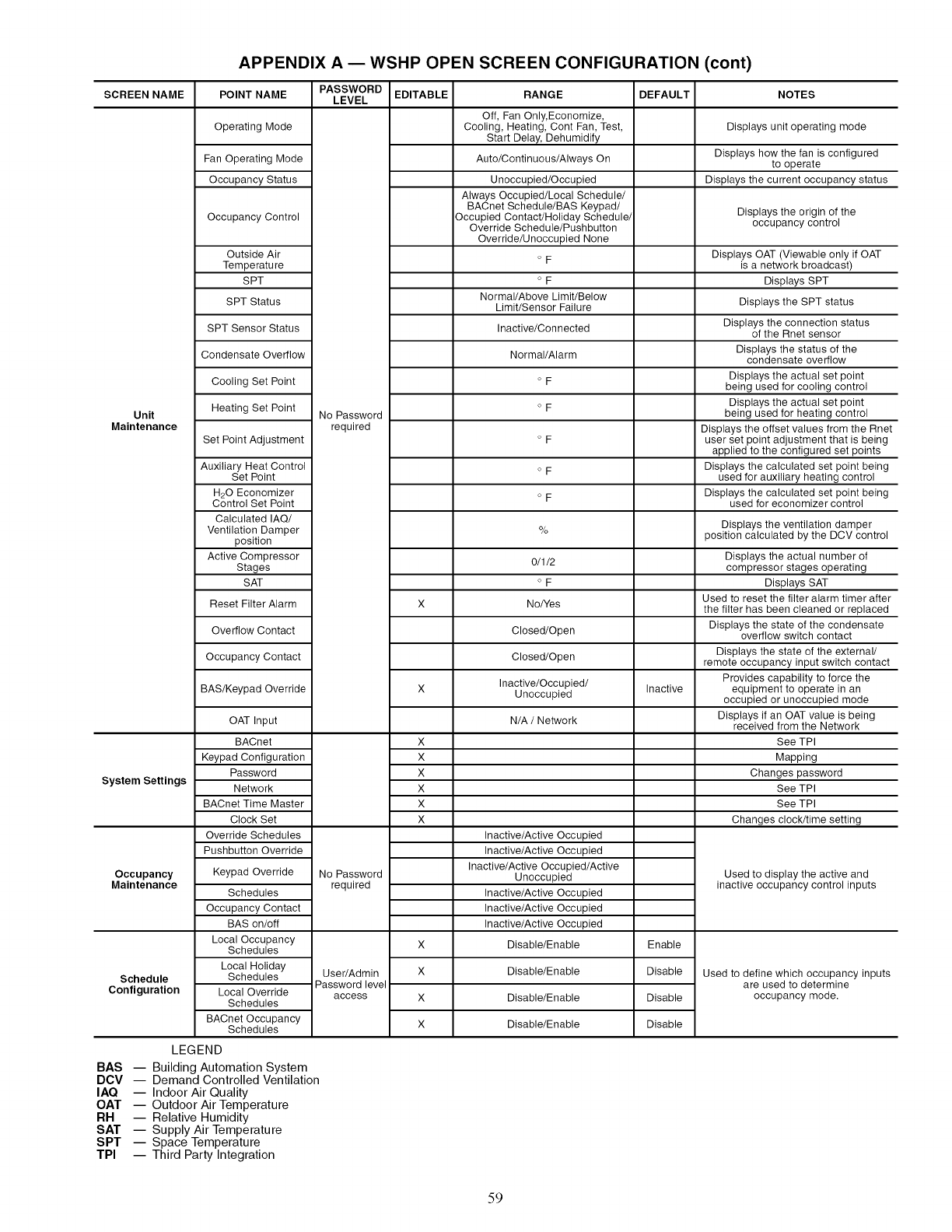
APPENDIX A EWSHP OPEN SCREEN CONFIGURATION (cont)
SCREEN NAME
Unit
Maintenance
System Settings
Occupancy
Maintenance
Schedule
Configuration
POINT NAME
Operating Mode
Fan Operating Mode
Occupancy Status
Occupancy Control
Outside Air
Temperatu re
SPT
SPT Status
SPT Sensor Status
Condensate Overflow
Cooling Set Point
Heating Set Point
Set Point Adjustment
Auxiliary Heat Control
Set Point
H20 Economizer
Control Set Point
Calculated IAQ/
Ventilation Damper
position
Active Compressor
Stages
SAT
Reset Filter Alarm
Overflow Contact
Occupancy Contact
BAS/Keypad Override
OAT Input
BACnet
Keypad Configuration
Password
Network
BACnet Time Master
Clock Set
Override Schedules
Pushbutton Override
Keypad Override
Schedules
Occupancy Contact
BAS on/off
Local Occupancy
Schedules
Local Holiday
Schedules
Local Override
Schedules
BACnet Occupancy
Schedules
PASSWORD EDITABLE RANGE DEFAULT NOTES
LEVEL
No Password
required
No Password
required
User/Admin
Password level
access
X
X
X
X
X
X
X
X
X
X
Off, Fan Only, Economize,
Cooling, Heating, Cont Fan, Test,
Start Delay, Dehumidify
Auto/Continuous/Always On
Unoccupied/Occupied
Always Occupied/Local Schedule/
BACnet Schedule/BAS Keypad/
Occupied Contact/Holiday Schedule/
Override Schedule/Pushbutton
Override/Unoccupied None
o F
o F
Normal/Above Limit/Below
Limit/Sensor Failure
Inactive/Con nected
Normal/Alarm
o F
o F
o F
o F
o F
%
0/1/2
o F
No/Yes
Closed/Open
Closed/Open
Inactive/Occupied/
Unoccupied
N/A /Network
Inactive/Active Occupied
Inactive/Active Occupied
Inactive/Active Occupied/Active
Unoccupied
Inactive/Active Occupied
Inactive/Active Occupied
Inactive/Active Occupied
Disable/Enable
Disable/Enable
Disable/Enable
Disable/Enable
Inactive
Enable
Disable
Disable
Disable
Displays unit operating mode
Displays how the fan is configured
to operate
Displays the current occupancy status
Displays the origin of the
occupancy control
Displays OAT (Viewable only if OAT
is a network broadcast)
Displays SPT
Displays the SPT status
Displays the connection status
of the Rnet sensor
Displays the status of the
condensate overflow
Displays the actual set point
being used for cooling control
Displays the actual set point
being used for heating control
Displays the offset values from the Rnet
user set point adjustment that is being
applied to the configured set points
Displays the calculated set point being
used for auxiliary heating control
Displays the calculated set point being
used for economizer control
Displays the ventilation damper
position calculated by the DCV control
Displays the actual number of
compressor stages operating
Displays SAT
Used to reset the filter alarm timer after
the filter has been cleaned or replaced
Displays the state of the condensate
overflow switch contact
Displays the state of the external/
remote occupancy input switch contact
Provides capability to force the
equipment to operate in an
occupied or unoccupied mode
Displays if an OAT value is being
received from the Network
See TPI
Mapping
Changes password
See TPI
See TPI
Changes clock/time setting
Used to display the active and
inactive occupancy control inputs
Used to define which occupancy inputs
are used to determine
occupancy mode.
LEGEND
BAS -- Building Automation System
DCV -- Demand Controlled Ventilation
IAQ -- Indoor Air Quality
OAT -- Outdoor Air Temperature
RH -- Relative Humidity
SAT -- Supply Air Temperature
SPT -- Space Temperature
TPI -- Third Party Integration
59
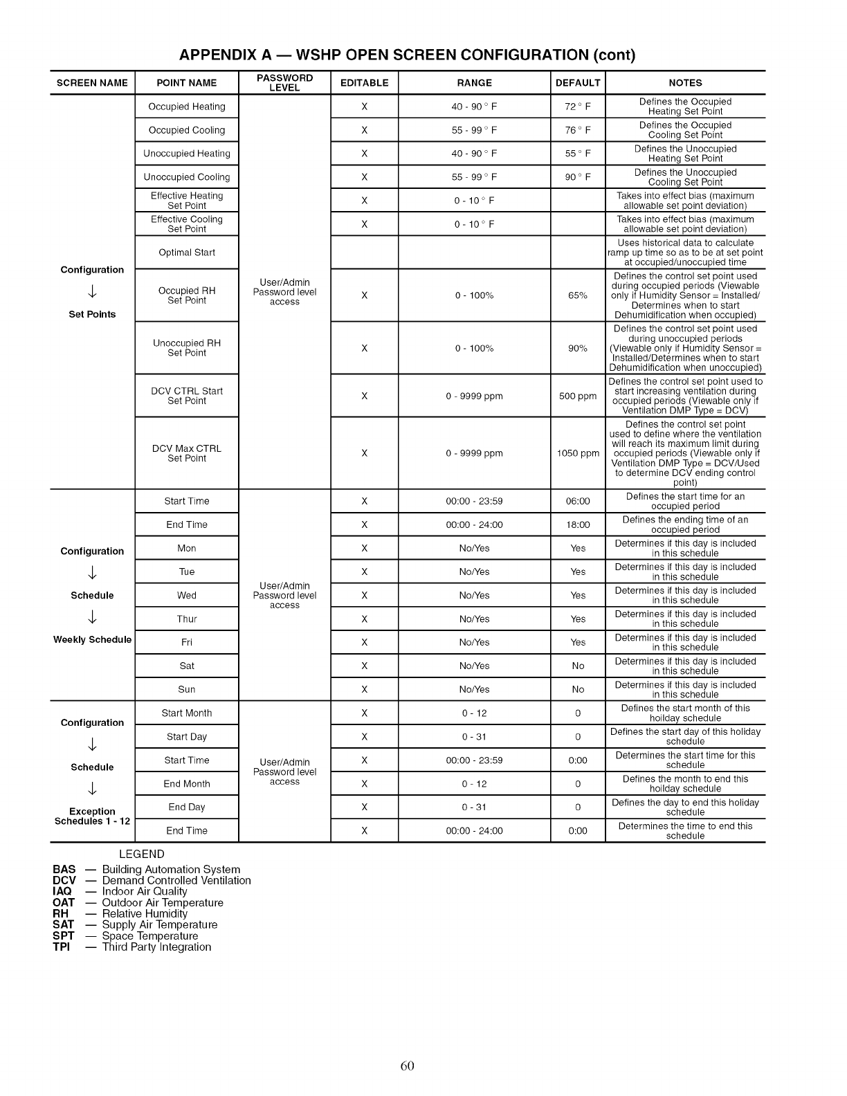
APPENDIX A EWSHP OPEN SCREEN CONFIGURATION (cont)
SCREEN NAME
Configuration
Set Points
Configuration
$
Schedule
$
Weekly Schedule
Configuration
Schedule
Exception
Schedules 1 - 12
POINT NAME
Occupied Heating
Occupied Cooling
Unoccupied Heating
Unoccupied Cooling
Effective Heating
Set Point
Effective Cooling
Set Point
Optimal Start
Occupied RH
Set Point
Unoccupied RH
Set Point
DCV CTRL Start
Set Point
DCV Max CTRL
Set Point
Start Time
End Time
Mon
Tue
Wed
Thur
Fri
Sat
Sun
Start Month
Start Day
Start Time
End Month
End Day
End Time
PASSWORD
LEVEL
User/Admin
Password level
access
User/Admin
Password level
access
User/Admin
Password level
access
EDITABLE
X
X
X
X
X
X
x
x
x
x
x
x
x
x
x
x
x
x
x
x
x
RANGE
40 - 90 o F
55 - 99 o F
40 - 90 o F
55 - 99 o F
O- 10 ° F
0-10°F
0 - 100%
0 - 100%
0 - 9999 ppm
0 - 9999 ppm
00:00 - 23:59
00:00 - 24:00
No/Yes
No/Yes
No/Yes
No/Yes
No/Yes
No/Yes
No/Yes
0-12
0- 31
00:00 - 23:59
0-12
O- 31
00:00 - 24:00
DEFAULT
72 ° F
76 ° F
55 ° F
90 ° F
65%
90%
500 ppm
1050 ppm
06:00
18:00
Yes
Yes
Yes
Yes
Yes
No
No
0
0
0:00
0
0
0:00
NOTES
Defines the Occupied
Heating Set Point
Defines the Occupied
Cooling Set Point
Defines the Unoccupied
Heating Set Point
Defines the Unoccupied
Cooling Set Point
Takes into effect bias (maximum
allowable set point deviation)
Takes into effect bias (maximum
allowable set point deviation)
Uses historical data to calculate
ramp up time so as to be at set point
at occupied/unoccupied time
Defines the control set point used
during occupied periods (Viewable
only if Humidity Sensor = Installed/
Determines when to start
Dehumidification when occupied)
Defines the control set point used
during unoccupied periods
(Viewable only if Humidity Sensor =
Installed/Determines when to start
Dehumidification when unoccupied)
Defines the control set point used to
start increasing ventilation during
occupied periods (Viewable only if
Ventilation DMP Type = DCV)
Defines the control set point
used to define where the ventilation
will reach its maximum limit during
occupied periods (Viewable only if
Ventilation DMP Type = DCV/Used
to determine DCV ending control
point)
Defines the start time for an
occupied period
Defines the ending time of an
occupied period
Determines if this day is included
in this schedule
Determines if this day is included
in this schedule
Determines if this day is included
in this schedule
Determines if this day is included
in this schedule
Determines if this day is included
in this schedule
Determines if this day is included
in this schedule
Determines if this day is included
in this schedule
Defines the start month of this
holiday schedule
Defines the start day of this holiday
schedule
Determines the start time for this
schedule
Defines the month to end this
holiday schedule
Defines the day to end this holiday
schedule
Determines the time to end this
schedule
LEGEND
BAS -- Building Automation System
DCV -- Demand Controlled Ventilation
IAQ -- Indoor Air Quality
OAT -- Outdoor Air Temperature
RH -- Relative Humidity
SAT -- Supply Air Temperature
SPT -- Space Temperature
TPI -- Third Party Integration
d0
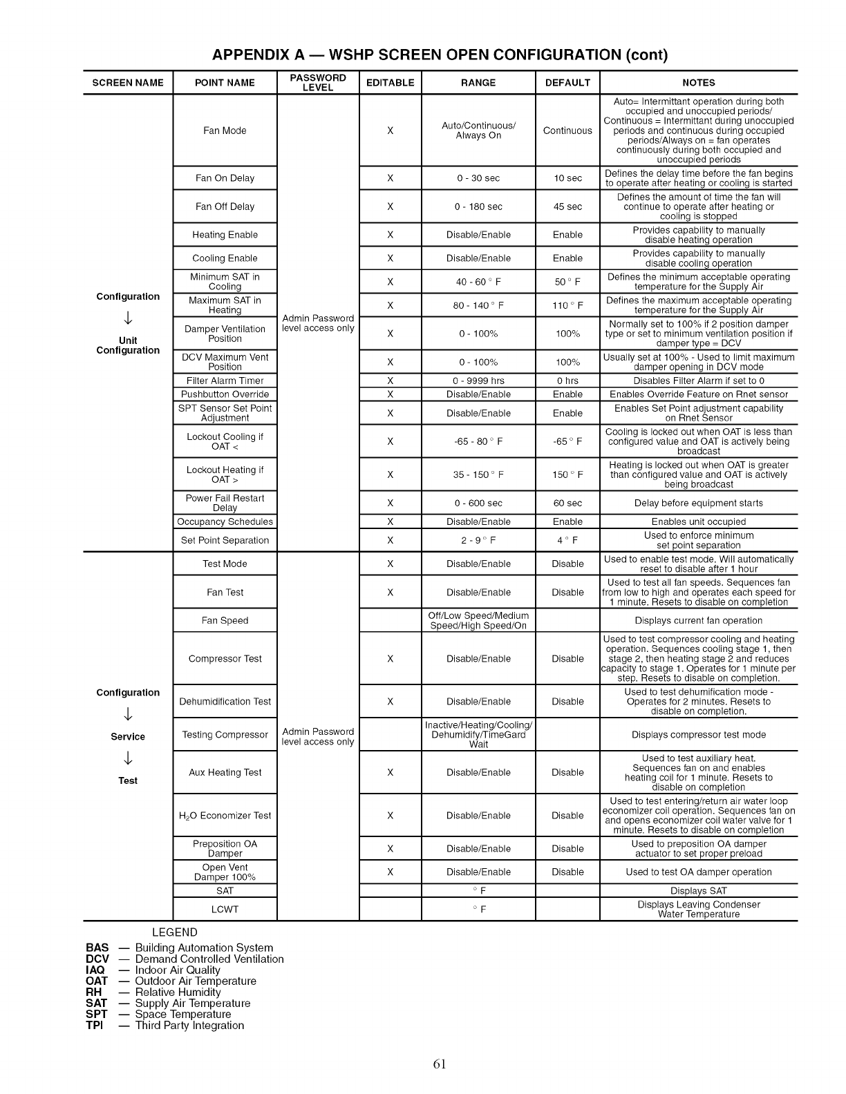
APPENDIX A EWSHP SCREEN OPEN CONFIGURATION (cont)
SCREEN NAME
Configuration
$
Unit
Configuration
Configuration
$
Service
$
Test
POINT NAME
Fan Mode
Fan On Delay
Fan Off Delay
Heating Enable
Cooling Enable
Minimum SAT in
Cooling
Maximum SAT in
Heating
Damper Ventilation
Position
DCV Maximum Vent
Position
Filter Alarm Timer
Pushbutton Override
SPT Sensor Set Point
Adjustment
Lockout Cooling if
OAT <
Lockout Heating if
OAT >
Power Fail Restart
Delay
Occupancy Schedules
Set Point Separation
Test Mode
Fan Test
Fan Speed
Compressor Test
Dehumidification Test
Testing Compressor
Aux Heating Test
H20 Economizer Test
Preposition OA
Damper
Open Vent
Damper 100%
SAT
LCWT
PASSWORD
LEVEL
Admin Password
level access only
Admin Password
level access only
EDITABLE
x
x
x
x
x
x
x
x
x
x
x
x
x
x
x
x
x
x
x
x
x
RANGE
Auto/Continuous/
Always On
0 - 30 sec
0 - 180 sec
Disable/Enable
Disable/Enable
40-60 ° F
80- 140 o F
0 - 100%
0 - 100%
0 - 9999 hrs
Disable/Enable
Disable/Enable
-65 - 80 ° F
35- 150 o F
0 - 600 sec
Disable/Enable
2-9OF
Disable/Enable
Disable/Enable
Off/Low Speed/Medium
Speed/High Speed/On
Disable/Enable
Disable/Enable
Inactive/Heating/Cooling/
Dehumidify/TimeGard
Wait
Disable/Enable
Disable/Enable
Disable/Enable
Disable/Enable
o F
o F
DEFAULT
Continuous
10 sec
45 sec
Enable
Enable
50 ° F
110 ° F
100%
100%
0 hrs
Enable
Enable
-65 o F
150 ° F
60 sec
Enable
4OF
Disable
Disable
Disable
Disable
Disable
Disable
Disable
Disable
NOTES
Auto= Intermittant operation during both
occupied and unoccupied periods/
Continuous = Intermittant during unoccupied
periods and continuous during occupied
periods/Always on = fan operates
continuously during both occupied and
unoccupied periods
Defines the delay time before the fan begins
to operate after heating or cooling is started
Defines the amount of time the fan will
continue to operate after heating or
cooling is stopped
Provides capability to manually
disable heating operation
Provides capability to manually
disable cooling operation
Defines the minimum acceptable operating
temperature for the Supply Air
Defines the maximum acceptable operating
temperature for the Supply Air
Normally set to 100% if 2 position damper
type or set to minimum ventilation position if
damper type = DCV
Usually set at 100% - Used to limit maximum
damper opening in DCV mode
Disables Filter Alarm if set to 0
Enables Override Feature on Rnet sensor
Enables Set Point adjustment capability
on Rnet Sensor
Cooling is locked out when OAT is less than
configured value and OAT is actively being
broadcast
Heating is locked out when OAT is greater
than configured value and OAT is actively
being broadcast
Delay before equipment starts
Enables unit occupied
Used to enforce minimum
set point separation
Used to enable test mode. Will automatically
reset to disable after 1 hour
Used to test all fan speeds. Sequences fan
from low to high and operates each speed for
1 minute. Resets to disable on completion
Displays current fan operation
Used to test compressor cooling and heating
operation. Sequences cooling stage 1, then
stage 2, then heating stage 2 and reduces
capacity to stage 1. Operates for 1 minute per
step. Resets to disable on completion.
Used to test dehumification mode -
Operates for 2 minutes. Resets to
disable on completion.
Displays compressor test mode
Used to test auxiliary heat.
Sequences fan on and enables
heating coil for 1 minute. Resets to
disable on completion
Used to test entering/return air water loop
economizer coil operation. Sequences fan on
and opens economizer coil water valve for 1
minute. Resets to disable on completion
Used to preposition OA damper
actuator to set proper preload
Used to test OA damper operation
Displays SAT
Displays Leaving Condenser
Water Temperature
LEGEND
BAS -- Building Automation System
DCV -- Demand Controlled Ventilation
IAQ -- Indoor Air Quality
OAT -- Outdoor Air Temperature
RH -- Relative Humidity
SAT -- Supply Air Temperature
SPT -- Space Temperature
TPI -- Third Party Integration
d!
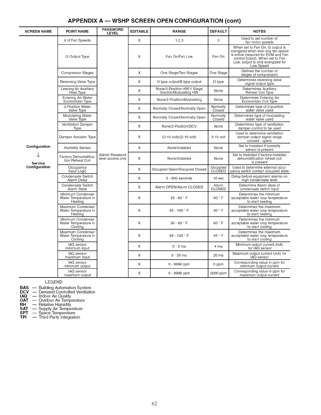
APPENDIX A EWSHP SCREEN OPEN CONFIGURATION (cont)
SCREEN NAME
Configuration
$
Service
Configuration
POINT NAME
# of Fan Speeds
G Output Type
Compressor Stages
Reversing Valve Type
Leaving Air Auxiliary
Heat Type
Entering Air Water
Economizer Type
2-Position Water
Valve Type
Modulating Water
Valve Type
Ventilation Damper
Type
Damper Actuator Type
Humidity Sensor
Factory Dehumidifica-
tion Reheat Coil
Occupancy
Input Logic
Condensate Switch
Alarm Delay
Condensate Switch
Alarm State
Minimum Condenser
Water Temperature in
Heating
Maximum Condenser
Water Temperature in
Heating
Minimum Condenser
Water Temperature in
Cooling
Maximum Condenser
Water Temperature in
Cooling
IAQ sensor
minimum input
IAQ sensor
maximum input
IAQ sensor
minimum output
IAQ sensor
maximum output
PASSWORD
LEVEL EDITABLE RANGE DEFAULT
X 1,2,3 3
Admin Password
level access only
X
X
X
X
X
X
X
X
X
X
X
X
X
X
X
X
X
X
X
Fan On/Fan Low Fan On
One Stage/Two Stages One Stage
O type output/B type output O type
None/2-Position HW/1 Stage None
Electric/Modulating HW
None/2-Position/Modulating None
Normally Closed/Normally Open Normally
Closed
Normally Closed/Normally Open Normally
Closed
None/2-Position/DCV None
(0-10 volt)/(2-10 volt) 0-10 volt
None/Installed None
None/Installed None
Occupied Open/Occupied Closed Occupied
CLOSED
5 - 600 seconds 10 sec
Alarm OPEN/Alarm CLOSED Alarm
CLOSED
25- 60 ° F 60 ° F
65- 100 ° F 90 ° F
30 - 60 ° F 60 o F
85- 120 ° F 95 ° F
0 - 5 ma 4 ma
5 - 20 ma 20 ma
0 - 9999 ppm 0 ppm
0 - 9999 ppm 2000 ppm
NOTES
Used to set number of
fan motor speeds
When set to Fan On, G output is
energized when ever any fan speed
is active (required for ECM and Fan
control board). When set to Fan
Low, output is only energized for
Low Speed
Defines the number of
stages of compression
Determines reversing valve
signal output type
Determines Auxiliary
Reheat Coil Type
Determines Entering Air
Economizer Coil Type
Determines type of 2-position
water valve used
Determines type of modulating
water valve used
Determines type of ventilation
damper control to be used
Used to determine ventilation
damper output signal range
(closed - open)
Set to Installed if humidity
sensor is present
Set to Installed if factory-installed
dehumidification reheat coil
is present
Used to determine external occu-
pancy switch contact occupied state
Delay before equipment alarms on
high condensate level
Determine Alarm state of
condensate switch input
Determines the minimum
acceptable water loop temperature
to start heating
Determines the maximum
acceptable water loop temperature
to start heating
Determines the minimum
acceptable water loop temperature
to start cooling
Determines the maximum
acceptable water loop temperature
to start cooling
Minimum output current (mA)
for IAQ sensor
Maximum output current (mA) for
IAQ sensor
Corresponding value in ppm for
minimum output current
Corresponding value in ppm for
maximum output current
LEGEND
BAS -- Building Automation System
DCV -- Demand Controlled Ventilation
IAQ -- Indoor Air Quality
OAT -- Outdoor Air Temperature
RH -- Relative Humidity
SAT -- Supply Air Temperature
SPT -- Space Temperature
TPI -- Third Party Integration
62
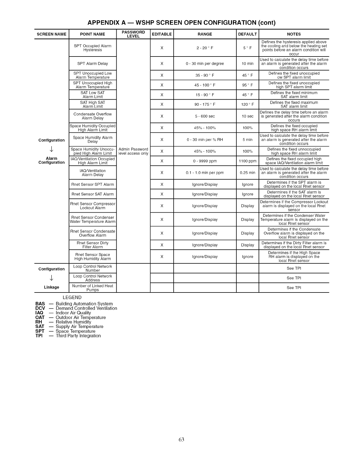
APPENDIX A EWSHP SCREEN OPEN CONFIGURATION (cont)
SCREEN NAME
Configuration
4.
Alarm
Configuration
Configuration
4.
Linkage
POINT NAME
SPT Occupied Alarm
Hysteresis
SPT Alarm Delay
SPT Unoccupied Low
Alarm Temperature
SPT Unoccupied High
Alarm Temperature
SAT Low SAT
Alarm Limit
SAT High SAT
Alarm Limit
Condensate Overflow
Alarm Delay
Space Humidity Occupied
High Alarm Limit
Space Humidity Alarm
Delay
Space Humidity Unoccu-
pied High Alarm Limit
IAQNentilation Occupied
High Alarm Limit
IAQ/Ventilation
Alarm Delay
Rnet Sensor SPT Alarm
Rnet Sensor SAT Alarm
Rnet Sensor Compressor
Lockout Alarm
Rnet Sensor Condenser
Water Temperature Alarm
Rnet Sensor Condensate
Overflow Alarm
Rnet Sensor Dirty
Filter Alarm
Rnet Sensor Space
High Humidity Alarm
Loop Control Network
Number
Loop Control Network
Address
Number of Linked Heat
Pumps
LEGEND
BAS -- Building Automation System
DCV -- Demand Controlled Ventilation
IAQ -- Indoor Air Quality
OAT -- Outdoor Air Temperature
RH -- Relative Humidity
SAT -- Supply Air Temperature
SPT -- Space Temperature
TPI -- Third Party Integration
PASSWORD
LEVEL EDITABLE RANGE DEFAULT
X 2-20 ° F 5 ° F
Admin Password
level access only
X
X
X
X
X
X
X
X
X
X
X
X
X
X
X
X
X
X
0 - 30 min per degree 10 min
35 - 90 ° F 45 o F
45- 100 ° F 95 ° F
15- 90 ° F 45 ° F
90- 175 ° F 120 ° F
5 - 600 sec 10 sec
45%- 100% 100%
0- 30 min per % RH 5 min
45%- 100% 100%
0 - 9999 ppm 1100 ppm
0.1 - 1.0 min per ppm 0.25 min
Ignore/Display Ignore
Ignore/Display Ignore
Ignore/Display Display
Ignore/Display Display
Ignore/Display Display
Ignore/Display Display
Ignore/Display Ignore
NOTES
Defines the hysteresis applied above
the cooling and below the heating set
points before an alarm condition will
occur
Used to calculate the delay time before
an alarm is generated after the alarm
condition occurs
Defines the fixed unoccupied
ow SPT alarm limit
Defines the fixed unoccupied
high SPT alarm limit
Defines the fixed minimum
SAT alarm limit
Defines the fixed maximum
SAT alarm limit
Defines the delay time before an alarm
is generated after the alarm condition
OCCUrs
Defines the fixed occupied
high space RH alarm limit
Used to calculate the delay time before
an alarm is generated after the alarm
condition occurs
Defines the fixed unnoccupied
high space RH alarm limit
Defines the fixed occupied high
space IAQNentilation alarm limit
Used to calculate the delay time before
an alarm is generated after the alarm
condition occurs
Determines if the SPT alarm is
displayed on the local Rnet sensor
Determines if the SAT alarm is
displayed on the local Rnet sensor
Determines if the Compressor Lockout
alarm is displayed on the local Rnet
sensor
Determines if the Condenser Water
Temperature alarm is displayed on the
local Rnet sensor
Determines if the Condensate
Overflow alarm is displayed on the
local Rnet sensor
Determines if the Dirty Filter alarm is
displayed on the local Rnet sensor
Determines if the High Space
RH alarm is displayed on the
local Rnet sensor
See TPI
See TPI
See TPI
63

Copyright 2009 Carrier Corporation
Manufacturer reserves the right to discontinue, or change at any time, specifications or designs without notice and without incurring obligations.
Catalog No. 04-53500055-01 Printed in U.S.A. Form 50PS-3Sl Pg 66 7-09 Replaces: 50PS-2Sl
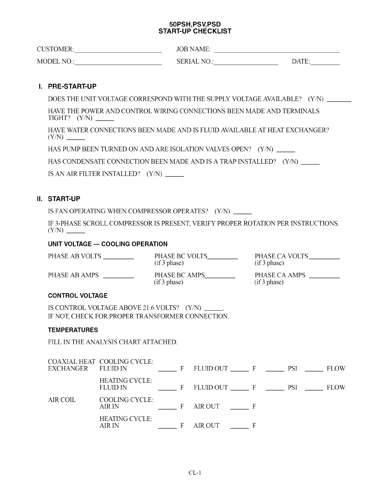
CUSTOMER:
MODEL NO.:
50PSH,PSV, PSD
START-UP CHECKLIST
JOB NAME:
SERIAL NO.: DATE:
PRE-START-UP
DOES THE UNiT VOLTAGE CORRESPOND WITH THE SUPPLY VOLTAGE AVAILABLE? (Y/N)
HAVE THE POWER AND CONTROL WIRING CONNECTIONS BEEN MADE AND TERMINALS
TIGHT? (Y/N)_
HAVE WATER CONNECTIONS BEEN MADE AND IS FLUID AVAILABLE AT HEAT EXCHANGER?
(Y/N) __
HAS PUMP BEEN TURNED ON AND ARE ISOLATION VALVES OPEN? (Y/N) __
HAS CONDENSATE CONNECTION BEEN MADE AND IS ATRAP INSTALLED? (Y/N) __
IS AN AIR FILTER INSTALLED? (Y/N) __
II. START-UP
IS FAN OPERATING WHEN COMPRESSOR OPERATES? (Y/N) __
IF 3-PHASE SCROLL COMPRESSOR IS PRESENT, VERIFY PROPER ROTATION PER INSTRUCTIONS.
(Y/N) __
UNIT VOLTAGE -- COOLING OPERATION
PHASE AB VOLTS PHASE BC VOLTS
(if 3 phase)
PHASE AB AMPS PHASE BC AMPS
(if 3 phase)
CONTROL VOLTAGE
IS CONTROL VOLTAGE ABOVE 21.6 VOLTS? (Y!N) __
IF NOT, CHECK FOR PROPER TRANSFORMER CONNECTION.
TEMPERATURES
FILL IN THE ANALYSIS CHART ATTACHED.
PHASE CA VOLTS
(if 3 phase)
PHASE CA MPS
(if 3 phase)
COAXIAL HEAT COOLING CYCLE:
EXCHANGER FLUID IN F FLUID OUT F
HEATING CYCLE:
FLUID IN F FLUID OUT F
AIR COIL COOLING CYCLE:
AIR IN F AIR OUT F
HEATING CYCLE:
AIR IN F AIR OUT F
PSI FLOW
PSI FLOW
CL-1
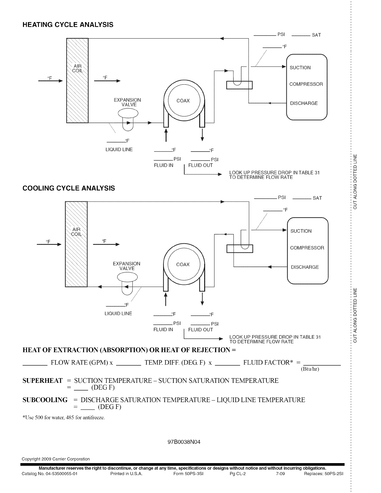
HEATING CYCLE ANALYSIS
AiR
"OCOILO
_\\\\\
oF
\\\\\_
oF
EXPANSION
VALVE
___°F
LIQUID LINE ___°F o F
__PSI --PSI
FLUID IN I FLUID OUT
I
-- PSI
° F
/
3
-- SAT
SUCTION
COMPRESSOR
DISCHARGE
LOOK UP PRESSURE DROP IN TABLE 31
TO DETERMINE FLOW RATE
COOLING CYCLE ANALYSIS
\\AIR\\
oF
\ \ , ,, \
, \ \, \,,
oF
EXPCp,ON
F t
LIQUID LINE ---°F --._F
__PSI --PSI
FLUID IN FLUID OUT
[
PSI
i
]
-- SAT
SUCTION
COMPRESSOR
DISCHARGE
J
LOOK UP PRESSURE DROP IN TABLE 31
TO DETERMINE FLOW RATE
HEAT OF EXTRACTION (ABSORPTION) OR HEAT OF REJECTION =
FLOW RATE (GPM) x TEMR DIFF. (DEG F) x FLUID FACTOR* =
(Btu/hr)
SUPERHEAT =SUCTION TEMPERATURE -SUCTION SATURATION TEMPERATURE
= __ (DEG F)
SUBCOOLING =DISCHARGE SATURATION TEMPERATURE - LIQUID LIN_ TEMPERATURE
= __ (DEG F)
*Use 500 for water, 485 for antifreeze.
97B0038N04
Copyright 2009 Carrier Corporation
Manufacturer reserves the right to discontinue, or change at any time, specifications or designs without notice and without incurring obligations.
Catalog No. 04-53500055-01 Printed in U.S.A. Form 50PS-3SI Pg CL-2 7-09 Replaces: 50PS-2Sl
iii
Z
-q
rh
iii
i-
i-
o
rh
Z
q
<
D
o
iii
Z
,-q
¢h
iii
l--
¢h
(D
Z
q
<
I--
D
