CASTLES TECHNOLOGY QP3000 QPROX User Manual 5 R1
CASTLES TECHNOLOGY CO., LTD. QPROX 5 R1
5. User Manual R1
Doc.# MAN-QPX0-FAET-02.00.0
Contactless Reader
QProx
User Manual
Standard Version
Version:02.00.0
Note:
Print Date:2008-08-05
Print Dept:Research and Development Department
Approved by Checked by Issued by
Castles Technology Co., Ltd.
2F, No 205, Beishin Rd Sec. 3, Hsin-Tien City, Taipei
Hsien, Taiwan R.O.C.
Tel: 886-2-8913-1771 Fax: 886-2-8913-1772
http://www.castech.com.tw
Doc.# MAN-QPX0-FAET-02.00.0
Contactless Reader
QProx
User Manual
Standard Version
Version:02.00.0
Note:
Castles Technology Co., Ltd.
2F, No 205, Beishin Rd Sec. 3, Hsin-Tien City, Taipei
Hsien, Taiwan R.O.C.
Tel: 886-2-8913-1771 Fax: 886-2-8913-1772
http://www.castech.com.tw
Copyright ©Castles Technology Co., Ltd. All Rights Reserved
Doc.# MAN-QPX0-FAET-02.00.0
Revision History
Version Date Editor Description
01.00.0 2008-08-05 Jackie Create
02.00.0 2010-03-26 Eaton
1. Added exterior and parts description of
QP2000 & QP3000.
2. Added QP2000 & QP3000 SAM card
installation procedures
3. QProx reader series’ external DC
adaptor supplies 12V/1A of power
through RS232 port.
4. Added pin assignment of internal pin
out 8 pins connector.
FCC Compliance Statement: This device complies with Part 15 of the FCC Rules. Operation is subject
to the following two conditions: (1) This device may not cause harmful interference, and (2) This device must
accept any interference received, including interference that may cause undesired operation. Note: The
manufacturer is not responsible for any radio or TV interference caused by unauthorized modifications to
this equipment. Such modifications could void the user’s authority to operate the equipment.
NOTE: This equipment has been tested and found to comply with the limits for a Class B digital device,
pursuant to part 15 of the FCC Rules. These limits are designed to pro-vide reasonable protection against
harmful interference in a residential installation. This equipment generates, uses and can radi-ate radio
frequency energy and, if not in-stalled and used in accordance with the in-structions, may cause harmful
interference to radio communications. However, there is no guarantee that interference will not occur in a
particular installation. If this equip-ment does cause harmful interference to radio or television reception,
which can be determined by turning the equipment off and on, the user is encouraged to try to correct the
interference by one or more of the fol-lowing measures:
—Reorient or relocate the receiving antenna.
—Increase the separation between the equip-ment and receiver.
—Connect the equipment into an outlet on a circuit different from that to which the re-ceiver is connected.
—Consult the dealer or an experienced radio/ TV technician for help.

Copyright ©Castles Technology Co., Ltd. All Rights Reserved
Doc.# MAN-QPX0-FAET-02.00.0 Page1/14
Table of Contents
TABLE OF CONTENTS...................................................................................................................1
1 INTRODUCTION ......................................................................................................................2
2 POWER ....................................................................................................................................4
3 PAKING LIST ...........................................................................................................................4
4 CONNECTOR AND PIN ASSIGMENT.....................................................................................5
4.1 RS232 Type........................................................................................................................................................................ 5
4.1.1 Standard D-SUB 9 Connector ............................................................. 5
4.2 USB Type ........................................................................................................................................................................... 5
4.2.1 Standard USB Type-A Connector .......................................................... 5
4.3 Internal Connector Pin Out ........................................................................................................................................... 6
5 INSTALLATION........................................................................................................................7
5.1 Power and RS232 Cable................................................................................................................................................. 7
5.2 USB Cable.......................................................................................................................................................................... 7
5.3 SAM Card Installation Procedures.............................................................................................................................. 8
5.4 Reader Stand Installation............................................................................................................................................. 11
5.5 Installation Notice.......................................................................................................................................................... 12
6 LED INDICATOR....................................................................................................................13
6.1 LED Indicator.................................................................................................................................................................. 13
6.2 Status Discription of LED Indicators ........................................................................................................................ 13
7 CONTACTLESS CARD LANDING ZONE..............................................................................14
Copyright ©Castles Technology Co., Ltd. All Rights Reserved
Doc.# MAN-QPX0-FAET-02.00.0 Page2/14
1 Introduction
Description of QP1000 and QP2000 readers:
1 LCD Display
2 LED (Blue)
3 LED (Orange)
4 LED (Green)
5 LED (Red)
6 Landing Zone
7 SAM Card Cover
Copyright ©Castles Technology Co., Ltd. All Rights Reserved
Doc.# MAN-QPX0-FAET-02.00.0 Page3/14
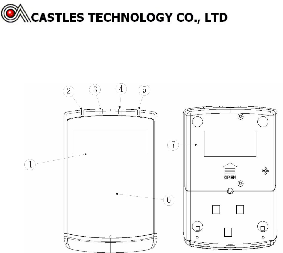
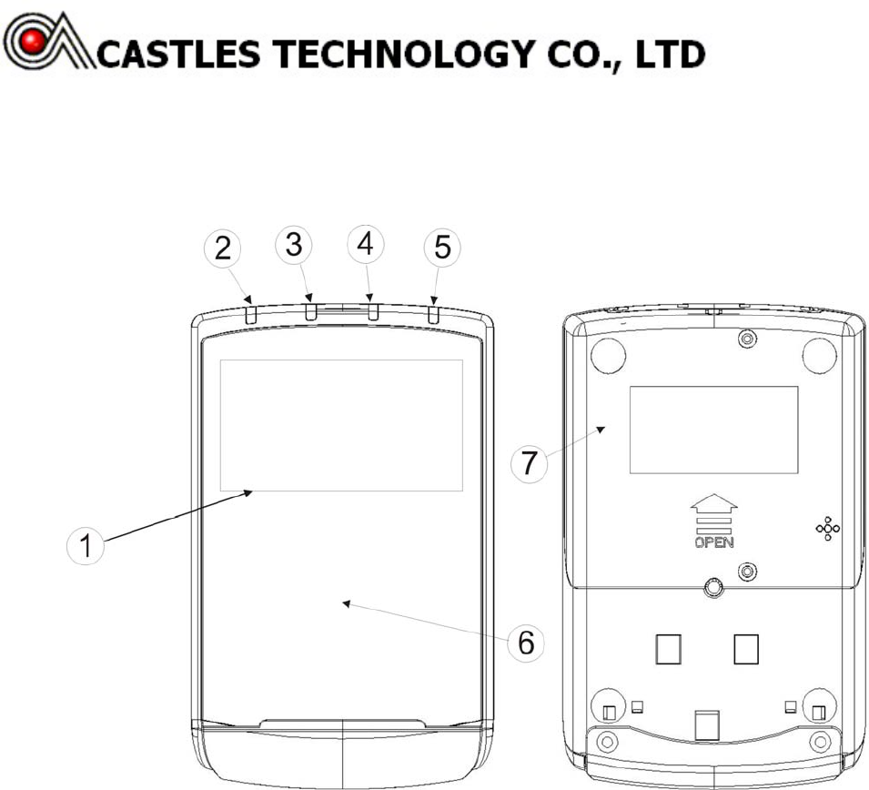
Description of QP3000 Reader:
1 LCD Display
2 LED (Blue)
3 LED (Orange)
4 LED (Green)
5 LED (Red)
6 Landing Zone
7 SAM Card Cover

Copyright ©Castles Technology Co., Ltd. All Rights Reserved
Doc.# MAN-QPX0-FAET-02.00.0 Page4/14
2 Power
There are several ways to supply power to a QProx reader:
9 By external DC adapter supplying 12V/1A of power through RS232 connector, please refer
to 錯誤! 找不到參照來源。.
9 By USB port supplying 5V/500mA, please refer to 錯誤! 找不到參照來源。.
3 Packing List
9 QPROX *1
9 ADAPTER*1(Optional)
9 USB/RS232 CABLE (Choose one of the cables prior to ordering)
Copyright ©Castles Technology Co., Ltd. All Rights Reserved
Doc.# MAN-QPX0-FAET-02.00.0 Page5/14
4 Connector and Pin Assignment
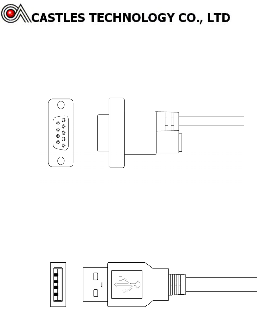
4.1 RS232 Type
4.1.1 Standard D-SUB 9 Connector
4.2 USB Type
4.2.1 Standard USB Type-A Connector
Copyright ©Castles Technology Co., Ltd. All Rights Reserved
Doc.# MAN-QPX0-FAET-02.00.0 Page6/14
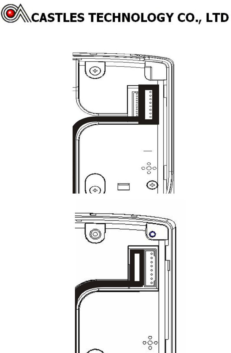
4.3 Internal Connector Pin Out
1.VEXT
2.TXD
3.RTS
4.RXD
5.CTS
6.GND
7.NC
8.NC
1.VEXT
2.VEXT
3.VDD5V
4.VDD5V
5.TXD
6.RTS
7.RXD
8.CTS
9.GND
10.USB D-
11.USB D+
12.GND
Copyright ©Castles Technology Co., Ltd. All Rights Reserved
Doc.# MAN-QPX0-FAET-02.00.0 Page7/14
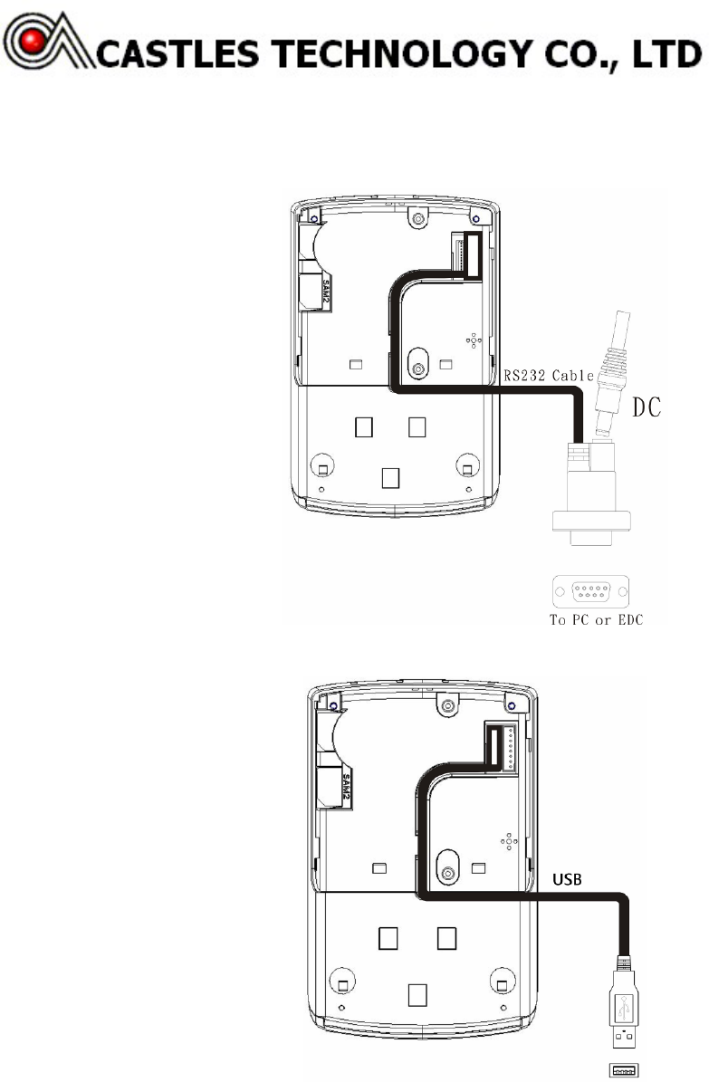
5 Installation
5.1 Power and RS232 Cable
5.2 USB Cable
Copyright ©Castles Technology Co., Ltd. All Rights Reserved
Doc.# MAN-QPX0-FAET-02.00.0 Page8/14
5.3 SAM Card Installation Procedures
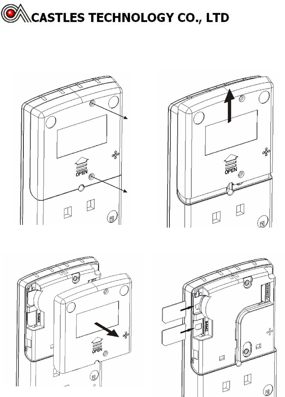
QP1000&QP2000 SAM Card Installation Procedures
Step 1. Unscrew SAM card cover screws Step 2. Push SAM card cover upward
Step 3. Remove SAM card cover Step 4. Insert SAM cards into SAM slots
Copyright ©Castles Technology Co., Ltd. All Rights Reserved
Doc.# MAN-QPX0-FAET-02.00.0 Page9/14
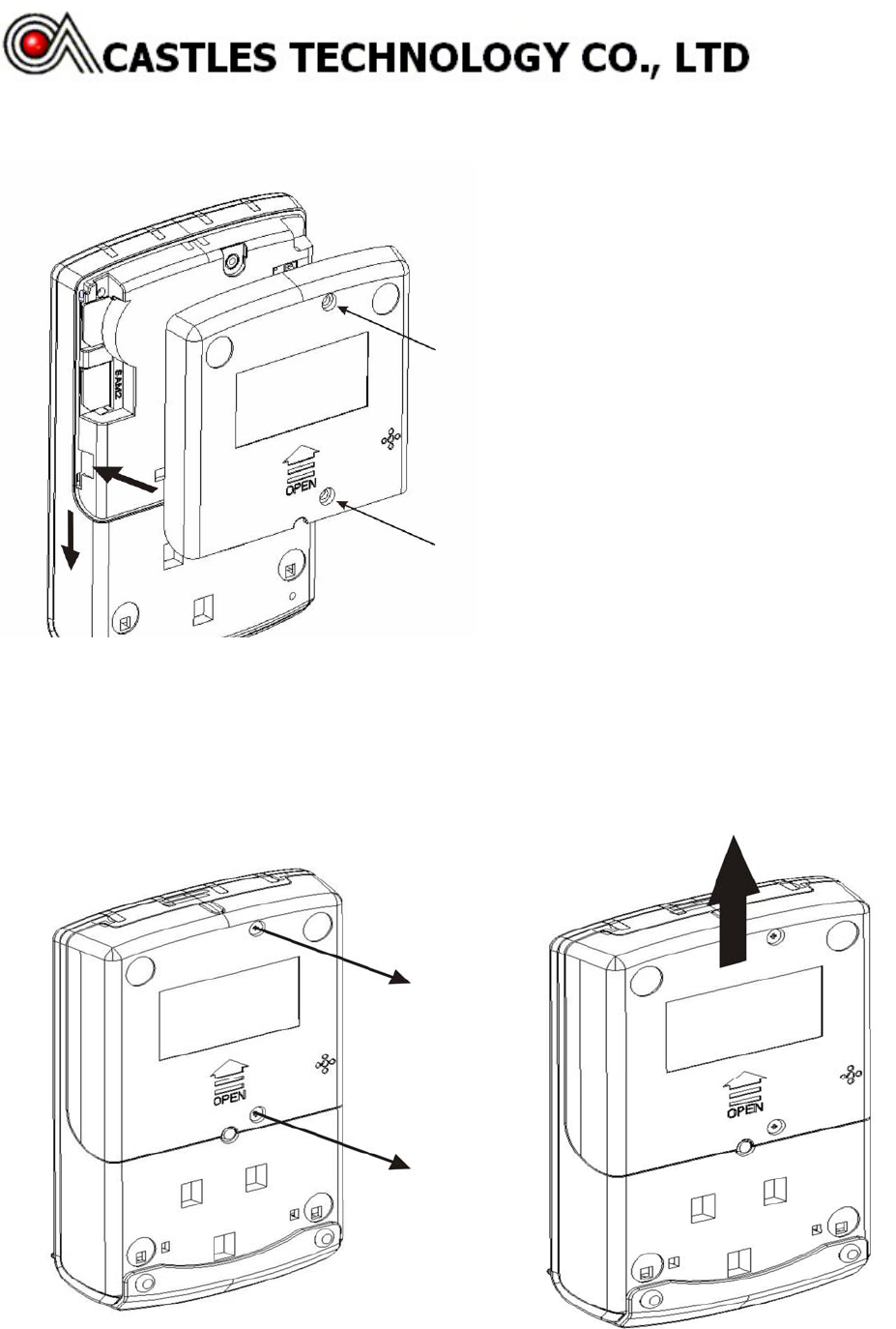
Step 5. Reinstall SAM card cover and screws back
QP3000 SAM Card Installation Procedures
Step1. Unscrew SAM card cover screws Step2. Push SAM card cover upward
Copyright ©Castles Technology Co., Ltd. All Rights Reserved
Doc.# MAN-QPX0-FAET-02.00.0 Page10/14
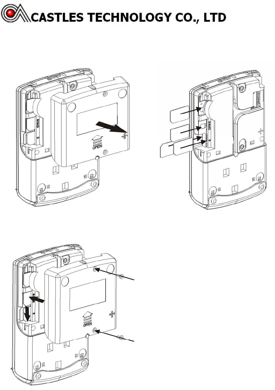
Step3. Remove SAM card cover Step4. Insert SAM cards into SAM slots
Step5. Reinstall SAM card cover and screws back
Copyright ©Castles Technology Co., Ltd. All Rights Reserved
Doc.# MAN-QPX0-FAET-02.00.0 Page11/14
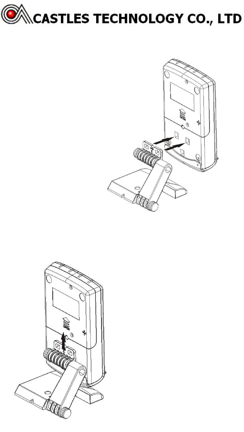
5.4 Reader Stand Installation
Step 1: Align and insert a reader stand to the fixture holes at the back of a reader
Step 2: Push the reader stand upward until hearing a click sound
Copyright ©Castles Technology Co., Ltd. All Rights Reserved
Doc.# MAN-QPX0-FAET-02.00.0 Page12/14
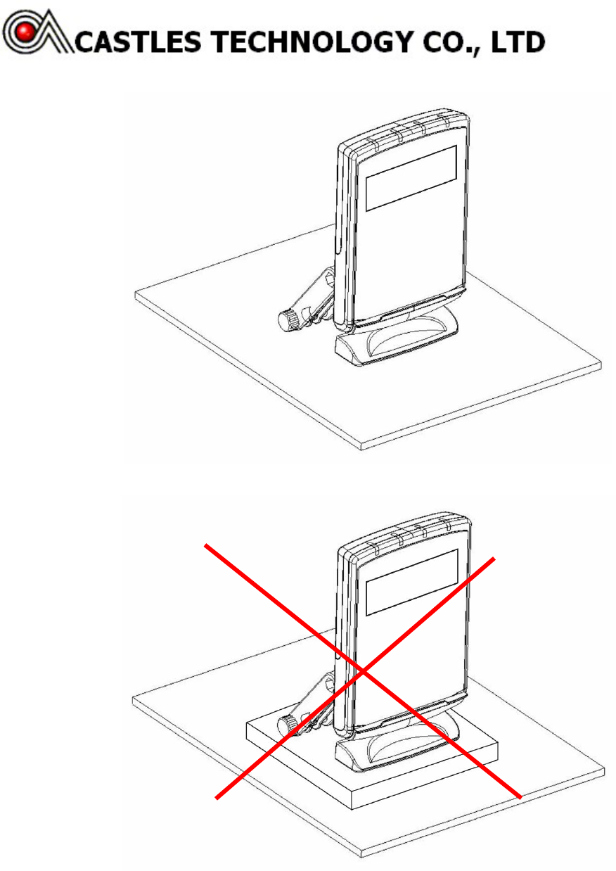
5.5 Installation Notice
In order to avoid interference, do not place reader on metallic surfaces
Copyright ©Castles Technology Co., Ltd. All Rights Reserved
Doc.# MAN-QPX0-FAET-02.00.0 Page13/14
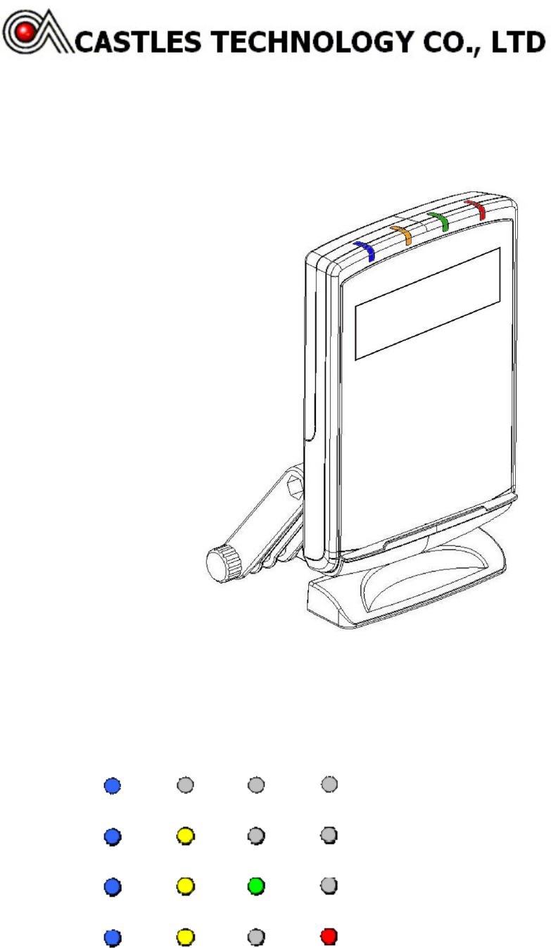
6 LED Indicator
6.1 LED Indicator
There are 4 LED indicators on a QProx. From left to right are blue, orange, green and red color LEDs
6.2 Status Description of LED Indicators
The states of the LED indicators are described below:
z After QProx is initialized and ready for transaction, the blue LED will light up. The blue LED indicates the
reader is ready for contactless card transactions (Pay Pass, Visa Wave, JCB or others).
z The blue and yellow LED indicates that a card has been detected and the transaction process is started.
z The blue, yellow and green LED indicates a SUCCESSUL transaction.
z The red LED indicates transaction FAILURE or malfunction.

Copyright ©Castles Technology Co., Ltd. All Rights Reserved
Doc.# MAN-QPX0-FAET-02.00.0 Page14/14
7 Contactless Card Landing Zone
The Land Zone icon is printed on the center of working area, which indicates the correct location to
detect user's card