CATEYE HRSENSORC Heart Rate Chest Strap User Manual SPD TR200DW280P
CATEYE Co., Ltd. Heart Rate Chest Strap SPD TR200DW280P
UserManual.wiki
>
CATEYE
>
HRSENSORC User Manual
>
Manual 2
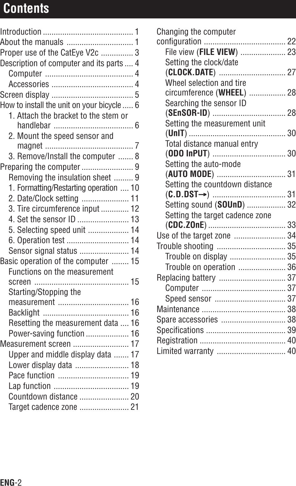
Contents
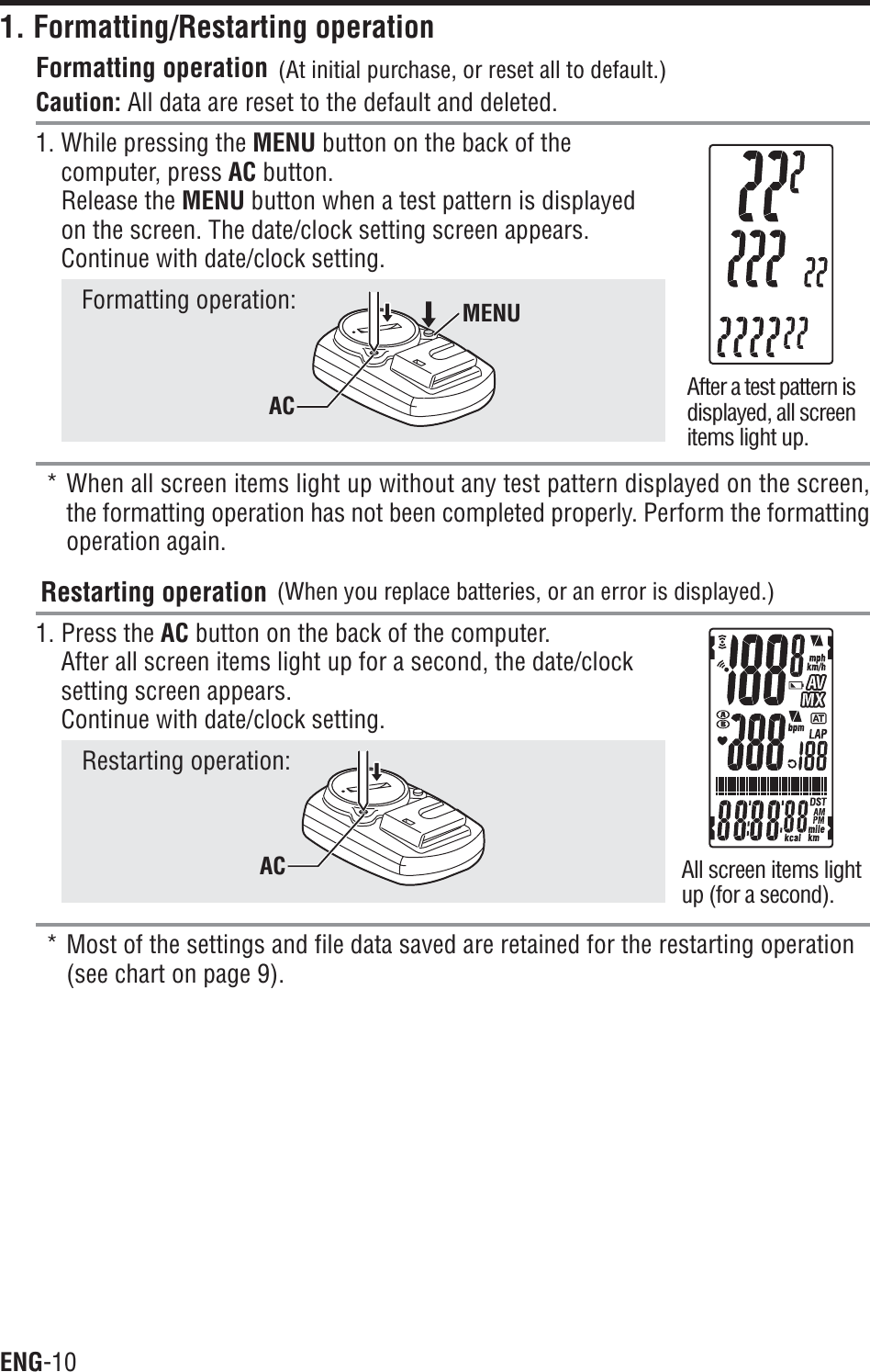
1.
Manual
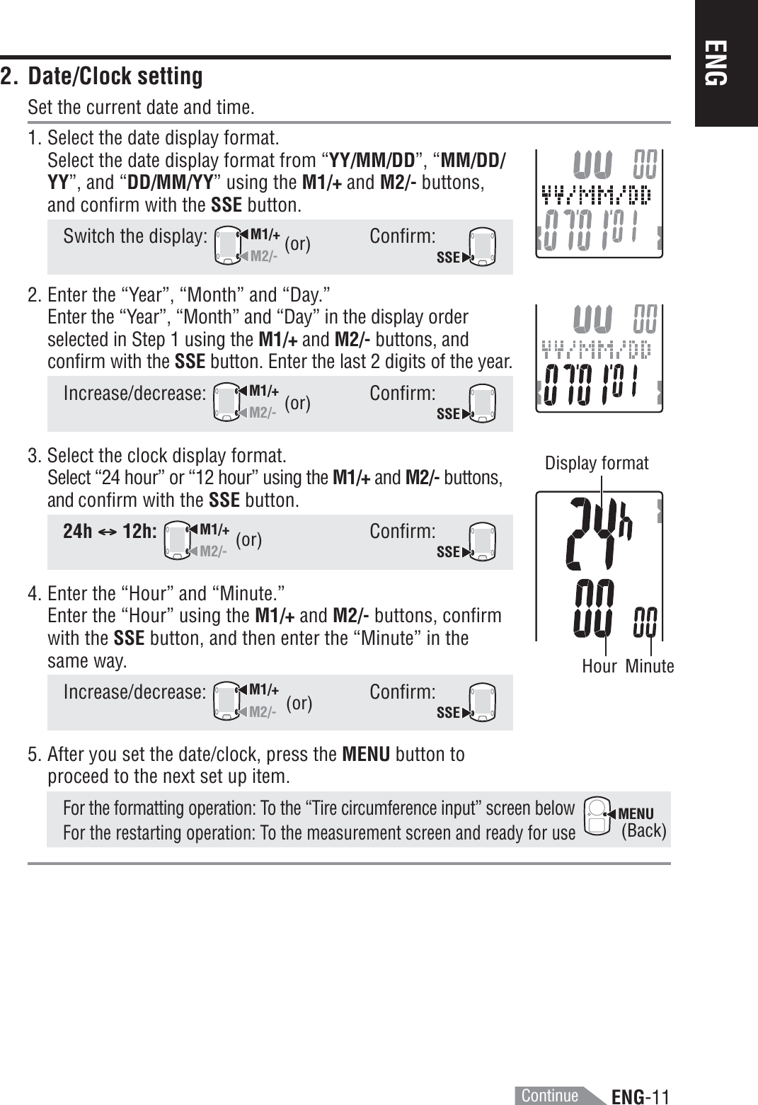
2.
Manual 2
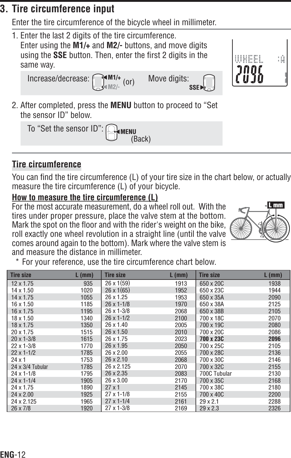
3.
Manual 3
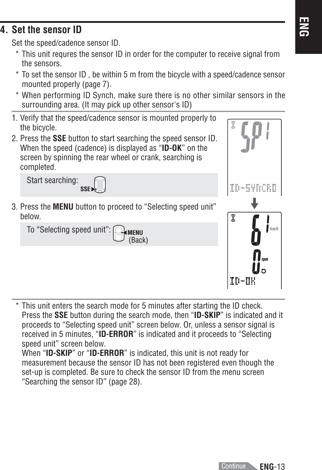
4.
Manual 4
5.
Manual 5
Manual 2
Navigation menu
Upload a User Manual
Namespaces
Wiki Guide
HTML
PDF
Info
Views
User Manual
Discussion / Help
Navigation
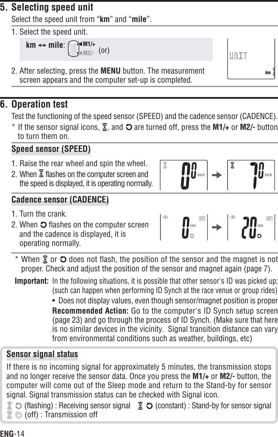
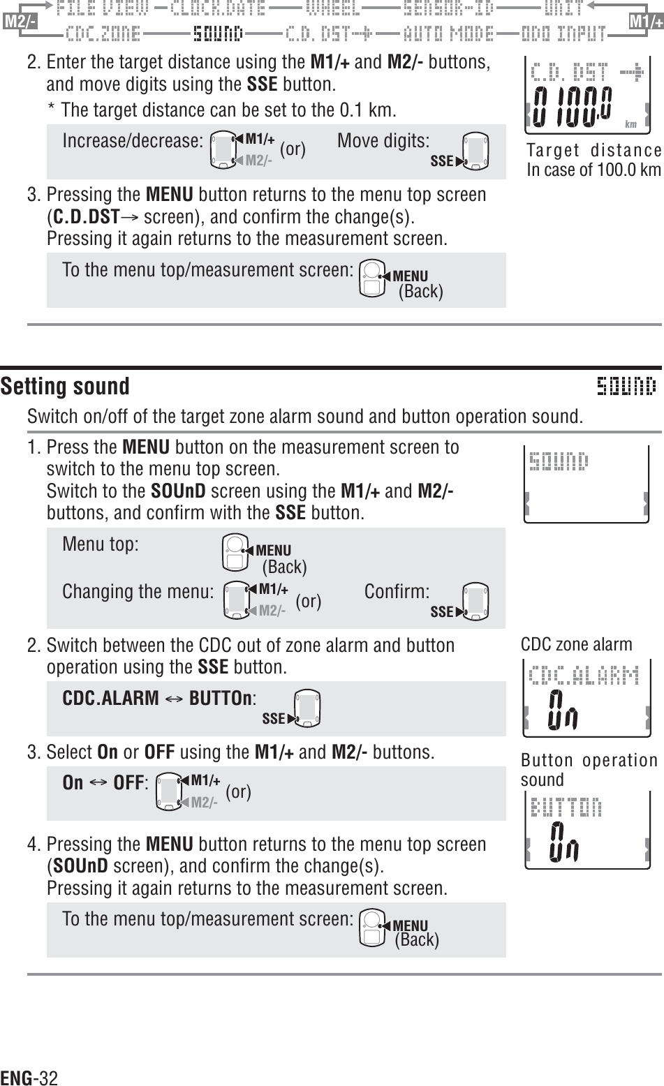
![ENG-17ENG123456M1/+M1/+M1/+1Current speedDisplays the current speed.Updated every second.2CadenceDisplays the number of pedal rotations per minute.Updated every second.Measurement screenUpper and middle display data*1: When the trip distance (DST) exceeds 10,000 km [mile], or the elapsed time (TM)exceeds 100 hours, [E] appears indicating further measurement is impossible. Clearthe data by resetting (page 16).*2: This device calculates the average excluding the time when you stop pedaling. Thisfeature produces actual averages, which are different from those with conventionalmodels that calculate it for the entire measurement time period.3Average speed *1Displays the average speed after the start of measurement.4Average cadence *2Displays the average cadence after the start of measurement.* The average will not be reflected when you stop pedaling.5Maximum speedDisplays the maximum speed after the start of measurement.Updated independently of starting/stopping measurement.6Maximum cadenceDisplays the maximum cadence after the start of measurement.Updated independently of starting/stopping measurement.](https://usermanual.wiki/CATEYE/HRSENSORC.Manual-2/User-Guide-841570-Page-19.png)

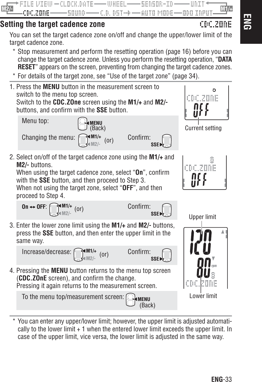
![ENG-39ENGSpecificationsUpper display Current speed 0.0 (4.0) <150.0 km/h [0.0 (3.0) <93.0 mph]For 27-inch tire sizeAverage speed 0.0 - 150.0 km/h [0.0 - 93.0 mph]Maximum speed 0.0 (4.0) < 150.0 km/h [0.0 (3.0) < 93.0 mph]Middle display Cadence 0 (20) < 199 rpmAverage cadence 0 < 199 rpmMaximum cadence 0 (20) < 199 rpmLower display Date ‘07.01.01 <'99.12.31(Display format can be switched)Clock 0:00’00” < 23:59’59”[AM 1:00’00” < PM 12:59’59”](Both 12 and 24-hour modes can be selected)Total time 0 < 99999 hourOdometer 0.0 < 9999.9/10000 < 999999 km [mile]Elapsed time 00’00”0 < 59’59”9 / 1:00’00” < 99:59’59”Trip distance 0.00 < 9999.99 km [mile]Countdown distance 9999.90 < 0.00 km [mile]Lap number L-01 < L-99Average lap speed in real time 0.0 < 150.0 km/h [0.0 < 93.0 mph]Lap timer 00’00”0 < 59’59”9 / 01:00’00” < 99:59’59”Trip lap distance in real time 0.00 < 9999.99 km [mile]Lap Upper display (average lap speed,maximum lap speed)Middle display (average lap cadence,Lap number,maximum lap cadence)Lower display (trip lap distance,lap time,split time)Control system 4-bit one-chip microcomputer, crystal oscillatorDisplay system Liquid crystal display (EL backlight)Speed/Cadence sensor signal detection systemNoncontact magnetic sensorSensor signal transmission and reception 2.4 GHz ISM BandCommunication range5 m (above 5 m, transmission distance may vary due to environmental conditions)Operating temperature range 32 °F< 104 °F[0°C< 40 °C](This product will not function appropriately when exceeding theWorking Temperature range. Slow response or black LCD at loweror higher temperature may happen respectively.)Storage temperature range -4 °F< 122 °F [-20 °C< 50 °C]Wheel circumference set range 0100 < 3999 mmPower supply/battery life Computer : CR2032 x 1 / Approx. 1 years (When using 1 hour/day)Speed sensor : CR2032 x 1 / Approx. 1 years (When using 1 hour/day)Dimensions/Weight Computer : 2-7/32” x 1-1/2” x 11/16” (56.0 x 38.0 x 17.3 mm) / 0.98 oz (28 g)(With the batteries)Speed sensor : 2-9/16” x 3-9/16” x 9/16” (65.0 x 90.5 x 14.4 mm) / 1.25 oz (36 g)(With the batteries)* When the elapsed time exceeds 100 hours, or the trip distance exceeds 9999.99 km/h, “E” appears in place ofthe average speed.* Designs and specifications are subject to change without notice, due to modifications or improvements.Displayfunctions](https://usermanual.wiki/CATEYE/HRSENSORC.Manual-2/User-Guide-841570-Page-41.png)