CC and C Technologies BT0002M Bluetooth module User Manual BT 0002M User s Guide
CC&C; Technologies, Inc. Bluetooth module BT 0002M User s Guide
Contents
- 1. Manual
- 2. Original manual
Original manual
Bluetooth Module
User’s Guide
Version 1.0
Federal Communication Commission Interference Statement
This equipment has been tested and found to comply with the limits for a Class B
digital device, pursuant to Part 15 of the FCC Rules. These limits are designed to
provide reasonable protection against harmful interference in a residential installation.
This equipment generates, uses and can radiate radio frequency energy and, if not
installed and used in accordance with the instructions, may cause harmful
interference to radio communications. However, there is no guarantee that
interference will not occur in a particular installation. If this equipment does cause
harmful interference to radio or television reception, which can be determined by
turning the equipment off and on, the user is encouraged to try to correct the
interference by one of the following measures:
? Reorient or relocate the receiving antenna.
? Increase the separation between the equipment and receiver.
? Connect the equipment into an outlet on a circuit different from that to which the
receiver is connected.
? Consult the dealer or an experienced radio/TV technician for help.
FCC Caution: To assure continued compliance, (example - use only shielded interface
cables when connecting to computer or peripheral devices). Any changes or
modifications not expressly approved by the party responsible for compliance could
void the user's authority to operate this equipment.
This device complies with Part 15 of the FCC Rules. Operation is subject to the
following two conditions: (1) This device may not cause harmful interference, and (2)
this device must accept any interference received, including interference that may
cause undesired operation.
IMPORTANT NOTE:
FCC Radiation Exposure Statement:
This equipment complies with FCC radiation exposure limits set forth for an
uncontrolled environment. This equipment should be installed and operated with
minimum distance 20cm between the radiator & your body.
This transmitter must not be co-located or operating in conjunction with any other
antenna or transmitter.
End Product Labeling
This transmitter module is authorized only for use in device where the antenna may be
installed such that 20cm may be maintained between the antenna and users (for
example access points, routers, wireless ADSL modems, and similar equipment). The
final end product must be labeled in a visible area with the following: “Contains TX
FCC ID: PANBT0002M”.
Tested to Comply with FCC Standards FOR HOME OR OFFICE USE
1. General Description
CC&C BT-0002M Bluetooth module class II is powered by CSR BlueCore2, which
with RF and baseband function been integrated in a single chip and was designed for
Bluetooth 2.4 GHz wireless applications. With band-pass filter, balun, crystal and
flash memory built on, it can reduce external components and provide a hardware
engineer with a speed and convenient way to complete their designs. Because of
compact sizes, they can easily design into customers’ target devices. For instance,
they can be used for PDA, notebook, tablet PC, keyboard and mouse as an internal
module. The BT-0002M develops the Bluetooth protocol stacks, profiles and with a
plenty of software development and integration experiences, CC&C can help
customer to design a specific device.
2. General Specification
Model Name BT-0002M
Product Name BT Module (CSRBC02)-Class II
Size 52x19x2.7mm
Weight 2.8 gram
Specification Bluetooth spec. 1.1
Antenna terminal 50 Ohm
Power Class Class-II
Digital interface Board to board connector for
USB interface or
UART interface
Operating Voltage 3.3V +/- 0.3V ; 5V (USB)
Operating Current TBD
Operating Temp. -10 ~ 70℃
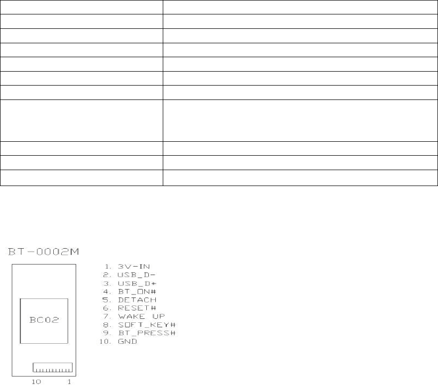
3. Pin assignment
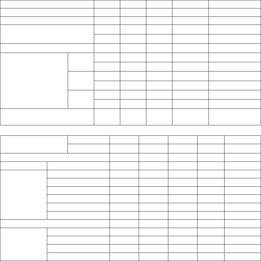
4. General Radio Characteristics
Transmitter Min Typ Max Unit Remarks
Maximum RF Output Power -2 02.55 dBm
RF Power control range 25 dBm
±140 ±175 kHz 11110000modModulation Characteristics
±115 kHz 1010mod
Initial Carrier Freq accuracy ±25 kHz PRBS9
±25 kHzDH1
±20 kHz/50us Drift Rate
±40 kHzDH3
±20 kHz/50us Drift Rate
±40 kHz
Carrier Freq drift
DH5
±20 kHz/50us Drift Rate
20dB bandwidth for
modulated carrier
|M-N|=2 -20 dBmIn-band spurious
emissions |M-N|>=3 -40 dBm
Receiver Min Typ Max Unit Remarks
Sensitivity DH1, DH3, DH5 --75 -dBm
C/ICO-Channel TBD 11 dB
C/ I1MHz TBD 0dB
C/ I2MHz TBD -30 dB *1
C/ I2MHz TBD -40 dB *1
C/ IImage TBD -9 dB
Interference
Performance
C/ IImage TBD -20 dB *1
Intermodulation Characteristics TBD dBm
30MHz-2000MHz -10 dBm
2000-2399MHz -27 dBm
2498-3000MHz -27 dBm
Out-of-band
Blocking
3GHz-12.75GHz -10 dBm
5. BlueCore 2-External Data
1) Device Features
¦ Low power 1.8V operation
¦ Small footprint in 96-Ball VFBGA Package (6x6mm)
¦ Fully qualified Bluetooth component
¦ 0.18µm CMOS technology
¦ Full speed class 2 Bluetooth operation with full 7 slave piconet support
¦ Support for 8Mbit external Flash
¦ Minimum external components
¦ Operates over full industrial temperature range ( -40 ≦ T ≦105°C)
2) General Description
BlueCore2-External is a single chip radio and baseband IC for Bluetooth 2.4GHz
radios implemented in CMOS technology. When used with external ROM
containing the CSR Bluetooth software stack, it provides a fully compliant Bluetooth
system for data and voice communications.
3) Applications
The design is optimised to require few external RF components to facilitate rapid
design of the application printed circuit board and therefore the fastest possible time
to market and lowest overall cost. Included in the device are auto-calibration and
built-in-self-test (BIST) routines to simplify development, type approval and
production test. All hardware and device firmware is fully compliant with the
Bluetooth specification.
¦ PC Notebooks
¦ Cellular Handsets
¦ Cordless Headsets
¦ Personal Digital Assistants (PDAs)
¦ Computer Accessories (Compact Flash, PCMCIA and SD cards)

4) Description of Functional Blocks
Radio Transceiver and Synthesiser
The receiver features a near-zero IF architecture that allows the channel filters to be
integrated on to the die. Sufficient out-of-band blocking specification at the LNA input
allows the radio to be used in close proximity to GSM and W-CDMA cellular phone
transmitters without being de-sensitised. The use of a digital FSK discriminator means
that no discriminator tank is needed and its excellent performance in the presence of
noise allows BlueCore2-External to exceed the Bluetooth requirements for co-channel
and adjacent channel rejection. Fast AGC is implemented by measuring the RSSI on
a slot-by-slot basis and adjusting the front-end LNA gain to keep the first mixer input
signal within a limited range. This improves the dynamic range of the receiver in
interference-limited environments.
The transmitter features a direct IQ modulator to minimise the frequency drift during a
transmit timeslot and results in a well controlled modulation index. A digital baseband
transmit filter provides the required spectral shaping.
The maximum transmit power of +7dBm allows BlueCore2-External to be used in
Class 2 and Class 3 radios and its support for transmit power control allows a simple
implementation for Class 1 with an external RF power amplifier.
The radio synthesiser is fully integrated with no requirement for an external VCO
screening can, varactor tuning diodes or LC resonators.
The radio has several built-in automatic calibration routines to maintain the radio
performance within specification across temperature and ageing. No LNA, PA or
TX/RX switch is required for Class 2 operation across the device’s full operating
temperature range.
Auxiliary Features
The device contains two clock sources: one reference oscillator for the RF carrier
frequency and one low frequency clock oscillator that is used as an interval timer
during sleep modes, i.e., Sniff, Hold or Park.
The reference oscillator requires an external crystal. Alternatively, the crystal
terminals can be driven from an external reference clock.The reference frequency can
be in the range of 8-32MHz in multiples of 250kHz.
The low frequency clock oscillator requires no external components. It is calibrated
automatically and maintains an accuracy of better than 250ppm. This oscillator
consumes less than 2µA and is permanently enabled.

Physical Layer DSP Hardware Engine
Dedicated logic is used for forward error correction, header error control, cyclic
redundancy check, encryption, data whitening, access code correlation and audio
transcoding to translate between A-law, µ-law and linear voice data from the host and
A-law, µ-law and Continuously Variable Slope Delta (CVSD) voice data over the air,
voice interpolation for lost packets and rate mismatches are performed by the
software.
Burst Mode Controller
During radio transmission the Burst Mode Controller (BMC) constructs a packet from
header information previously loaded into memory-mapped registers by the software
and payload data/voice taken from the appropriate ring buffer in RAM. During radio
receptions, the burst mode controller stores the packet header in memory-mapped
registers and the payload data in the appropriate ring buffer in RAM. This architecture
minimises the intervention required by the processor during transmission and
reception.
Micro-controller, Interrupt Controller and Event Timer
The micro-controller, interrupt controller and event timer run the Bluetooth software
stack and control the radio and host interfaces. A 16-bit RISC micro-controller is used
for low power consumption and efficient use of memory.
Memory Management Unit
The memory management unit provides a number of dynamically allocated ring
buffers that hold the data which is in transit between the host and the air or vice versa.
The dynamic allocation of memory ensures efficient use of the available RAM and is
performed by a hardware memory management unit to minimise the overheads on the
processor during data/voice transfers.
RAM
32Kbytes of on-chip RAM is provided and is shared between the ring buffers used to
hold voice/data for each active connection and the general purpose memory required
by the Bluetooth stack.
ROM
Up to 8Mbits of external Flash or masked programmed ROM (16 bit data words) can
be attached giving maximum flexibility for running complete applications on chip. The
ROM can be programmed over the synchronous serial/UART or USB interfaces after
the device is mounted in the target application.

5) CSR Bluetooth Software Stack
BlueCore2-External is supplied with Bluetooth stack firmware that runs on its
microcontroller and is resident in the external Flash memory. The stack occupies
4Mbits of storage.
The BlueCore Stack Software is compliant with the Bluetooth v1.1 specification. It
implements all the features described in the specification, including optional features.
Piconets: up to seven slaves.
Power Saving: Hold, Sniff and Park
Data integrity: Channel Quality Driven Data Rate (CQDDR) and RSSI
Audio: full support for SCO
Role Switch: can reverse master/slave relationship
Device Firmware Upgrade
BlueCore2-External is supplied with boot loader software which implements a
standard Device Firmware Upgrade (DFU) capability. This allows new firmware to be
uploaded to the external Flash memory through BlueCore2-External's UART/USB
ports.
Additional Software for Host Implementation
A companion device, BlueCore2-PC can be ordered which includes software for a full
Windows 98/ME or Windows 2000 Bluetooth host-side stack and application together
with the IC hardware described in this datasheet. Contact CSR for more details.
Additional Software for Other Embedded Applications
When the upper layers of the Bluetooth protocol stack are run as firmware on
BlueCore2-External a UART software driver is supplied that presents the HCI, L2CAP,
RFCOMM and Service discovery APIs to higher Bluetooth stack layers running on the
host. The code is provided as .C. source or object code. Other software drivers can be
developed on request. Contact CSR Sales for more information.
Casira Development System
This is available to allow the evaluation of BlueCore2- External hardware and software
and as the base of a toolkit for developing host software. Contact CSR Sales for more
information.
Profiles Supported Via HCI
The supplied software stack is a full implementation of Bluetooth up to and including
HCI, so all profiles and associated applications are supported.

Application Specific Software Development Environment
Firmware supplied with BlueCore2-External contains a protected user software
execution environment as a Virtual Machine (VM). The user may write custom
application code to run on the BlueCore VM using the BlueLab software development
kit, available separately from CSR. This code will then execute alongside the main
BlueCore firmware. The user is able to make calls to the BlueCore firmware for
various operations.
The execution environment is structured so the user application does not adversely
affect the main software routines, thus ensuring that the Bluetooth stack software
component does not need re- qualification when the application is changed.
Using the VM and BlueLab, the user is able to develop applications such as a
cordless headset or other profiles without the requirement of a host controller.
BlueLab is supplied with example code, including a full implementation of the headset
profile.
6) External Interfaces
Transmitter/Receiver Inputs/Output
Terminals TX_A and TX_B form a balanced current output. They require a DC
connection to VDD and should be connected through a balun to the antenna. The
output impedance is capacitive and remains constant irrespective of whether the
transmitter is enabled or disabled. For Class 2 operation these terminals also act as
differential receive input terminals with an internal TX/RX switch. For Class 1
operation the RF_IN ball is provided, which is single-ended and presents a capacitive
input. A swing of up to 0.5V rms can be tolerated at this terminal. An external antenna
switch can be
connected to RF_IN.
Asynchronous Serial Data Port (UART) and USB Port
UART_TX, UART_RX, UART_RTS, and UART_CTS form a conventional
asynchronous data serial port. The interface is designed to operate correctly when
connected to other UART devices such as the NS16550A. The signalling levels are
0V and VDD_PADS. The interface is programmable over a variety of bit rates; no,
even or odd parity; one or two stop bits and hardware flow control on or off. The
default condition on power-up is pre-assigned in the external Flash memory.
The maximum UART data rate is 1.5Mbit/s. Two-way hardware flow control is
implemented by UART_RTS and UART_CTS. UART_RTS is an output and is active
low. UART_CTS is an input and is active low. These signals operate according to
normal industry

convention.
The port carries a number of logical channels: HCI data (both SCO and ACL), HCI
commands and events, L2CAP API, RFCOMM API, Service Discovery API and
device management. For the UART, these are combined into a robust tunneling
protocol, BlueCore Serial Protocol (BCSP), where each channel has its own software
flow control and cannot block other data channels. In addition, the Bluetooth
specification part H4 format is supported.
Alternatively a firmware version is available to support full speed (12Mbit/s) USB.
USB_D+ and USB_D- are available on dedicated terminals. Both Open Host
Controller Interface (OHCI) and Upper Host Controller Interfaces (UHCI) are
supported.
The firmware in Flash can be downloaded through this port by DFU if the CSR-
supplied boot loader is first programmed.
Firmware shipped with BlueCore2-External includes security features to prevent
misuse of this upgrade facility.
PCM Codec Interface
PCM_OUT, PCM_IN, PCM_CLK, PCM_SYNC carry up to three bidirectional
channels of voice data, each at 8 ks/s. The format of the PCM samples can be 8-bit
A-law, 8-bit µ-law, 13-bit linear or 16-bit linear. The PCM_CLK and PCM_SYNC
terminals can be configured as inputs or outputs depending on whether BlueCore2-
External is the master or slave of the PCM interface.
BlueCore2-External interfaces directly to PCM audio devices such as the:
Qualcomm MSM 3000 series and MSM 5000 series CDMA devices,
OKI MSM7705 four channel µ/A-law codec,
Motorola MC145481 8-bit µ/A-law codec,
Motorola MC145483 13-bit linear codec and the
Mitel MT93LI6 Echo cancelling codec.
BlueCore2-External is also compatible with the
Motorola SSITM interface.
Synchronous Serial Port
BlueCore2-External is a slave device using terminals SPI_MOSI, SPI_MISO,
SPI_CLK and SPI_CSB. This interface is used for program emulation/debug and IC
test. It is also the means by which the external Flash ROM may be programmed .in
situ. before any 'boot' program is loaded. The designer should be aware that no
security protection is built into the hardware or firmware associated with this port.
Parallel PIO Port
Fifteen lines of programmable bidirectional I/O are provided. PIO[11:0] are powered

from VDD_PIO and AIO[2:0] are powered from VDD_MEM. PIO[0] and PIO[1] are
normally dedicated to TXEN and RXEN, but they are available for general use. Any of
the PIO lines can be configured as interrupt request lines or as wake-up lines from
sleep modes. PIO[6] can be configured as a request line for an external clock source.
This is useful when the clock to BlueCore2- External is provided from a system ASIC.
I2C Interface
PIO[3] and PIO[2] can be used to form a master I2C interface. The interface is formed
using software to drive these lines and is thus suited only to relatively slow functions
such as driving a dot matrix LCD display, a keyboard scanner or an EEPROM.